CN100339930C - Colour kinescope - Google Patents
Colour kinescope Download PDFInfo
- Publication number
- CN100339930C CN100339930C CNB001352075A CN00135207A CN100339930C CN 100339930 C CN100339930 C CN 100339930C CN B001352075 A CNB001352075 A CN B001352075A CN 00135207 A CN00135207 A CN 00135207A CN 100339930 C CN100339930 C CN 100339930C
- Authority
- CN
- China
- Prior art keywords
- electron
- anode
- lens
- target
- electrode
- Prior art date
- Legal status (The legal status is an assumption and is not a legal conclusion. Google has not performed a legal analysis and makes no representation as to the accuracy of the status listed.)
- Expired - Fee Related
Links
Images


Classifications
-
- H—ELECTRICITY
- H01—ELECTRIC ELEMENTS
- H01J—ELECTRIC DISCHARGE TUBES OR DISCHARGE LAMPS
- H01J29/00—Details of cathode-ray tubes or of electron-beam tubes of the types covered by group H01J31/00
- H01J29/46—Arrangements of electrodes and associated parts for generating or controlling the ray or beam, e.g. electron-optical arrangement
- H01J29/48—Electron guns
- H01J29/50—Electron guns two or more guns in a single vacuum space, e.g. for plural-ray tube
-
- H—ELECTRICITY
- H01—ELECTRIC ELEMENTS
- H01J—ELECTRIC DISCHARGE TUBES OR DISCHARGE LAMPS
- H01J29/00—Details of cathode-ray tubes or of electron-beam tubes of the types covered by group H01J31/00
- H01J29/46—Arrangements of electrodes and associated parts for generating or controlling the ray or beam, e.g. electron-optical arrangement
- H01J29/48—Electron guns
- H01J29/51—Arrangements for controlling convergence of a plurality of beams by means of electric field only
-
- H—ELECTRICITY
- H01—ELECTRIC ELEMENTS
- H01J—ELECTRIC DISCHARGE TUBES OR DISCHARGE LAMPS
- H01J29/00—Details of cathode-ray tubes or of electron-beam tubes of the types covered by group H01J31/00
- H01J29/46—Arrangements of electrodes and associated parts for generating or controlling the ray or beam, e.g. electron-optical arrangement
- H01J29/48—Electron guns
- H01J29/50—Electron guns two or more guns in a single vacuum space, e.g. for plural-ray tube
- H01J29/503—Three or more guns, the axes of which lay in a common plane
Abstract
In an electron gun assembly, its main convergence lens is composed of a focus electrode to which a focus voltage is applied, an anode electrode to which a high anode voltage is applied, and an intermediate electrode which is provided between the focus and anode electrodes and to which a high intermediate potential higher than the focus voltage and lower than the anode voltage is applied. The anode and intermediate electrodes are each a cylindrical unit long in the in-line direction. In the direction crossing at right angles with the in-line direction of the cylindrical units, the diameter of the opening in the anode electrode is set smaller than that of the opening in the intermediate electrode, thereby forming a multiple pole lens into a main electron lens of large aperture.The aberration in a large aperture main lens is decreased, large aperture is realized, assembly precision is and a preferred image property can be obtained in the whole image area.
Description
Technical field
The present invention relates to the electron gun of tricolour picture tube, particularly relate to the color picture tube that the electron gun that possesses the heavy caliber main lens is housed.
Background technology
Usually, color picture tube as shown in Figure 1, possesses the shell that engages glass awl (funnel) 12 formations that are one by panel 11 and with this panel, be formed with the phosphor screen 13 (target) that 3 look luminescent coatings of the strip that sends indigo plant, green, ruddiness or point-like constitute at this panel 1 inner surface, relative with this phosphor screen 13, side is equipped with the shadow mask 14 that forms many holes (aperture) within it.On the other hand, in the neck 15 of glass awl 12, be provided with the electron gun 17 of emission three-beam electron- beam 16B, 16G, 16R.And bore the level that the deflecting coil 18 in 12 outsides produces and the effect deflect of vertical deflection magnetic field being installed on glass from three-beam electron-beam 16B, the 16G of 17 emissions of this electron gun, 16R, by shadow mask 14 directive phosphor screens 13, this phosphor screen 13 demonstrates coloured image under the level of electron beam and vertical scanning.
In recent years, the definition to this color picture tube requires more and more higher.The diameter that is formed at the beam spot on the phosphor screen 13 is the key factor of decision definition, and the diameter of this beam spot is determined by the focusing performance of electron gun usually.
This focusing performance depends on diameter, multiplying power of the bore of main lens, imaginary object point etc. usually.That is the main lens bore is big more, and imaginary object point diameter is more little, and multiplying power is more little, then can make the beam spot diameter more little, can promote clearness.
Existing electron gun, USP4 for example, 712,043, Japanese patent laid-open 8-22780 and spy open flat 9-320485 number etc. in the described electron gun, be provided with between focusing electrode and anode and have than focus voltage height and the target that be roughly intermediate potential lower than anode voltage, it is the shared peristome of oval-shaped three-beam electron-beam that its each relative face is provided with section long on the word order direction.
Electron gun with this spline structure forms the expansion electric field that extends on the electron beam direction of advance, also form continuous electric field simultaneously on the word order direction, forms bigbore main lens like this.In this electron gun, utilize bigbore main lens, can make the beam spot that focuses on the phosphor screen become littler, can realize high definition.
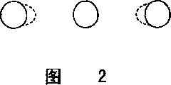
But the electron gun of this structure, utilize three-beam electron-beam shared, when the electrode of long oval-shaped profile opening focuses on the word order direction, as shown in Figure 2, limit bundle (side beam) is producing halation (halo) on the direction of middle bundle.For fear of such phenomenon takes place, in the design phase of electron gun, adopt following method, just when the structure of design electrode, make the limit bundle in advance to middle Shu Fangxiang bending, to the oblique incidence of heavy caliber main lens.She Ji electrode structure like this, utilize the method for limit bundle to the oblique incidence of heavy caliber main lens, the limit bundle is passed through in the heavy caliber main lens near the relatively more uniform part of the Potential distribution of middle bundle, and, to the result of heavy caliber main lens oblique incidence be the part by middle bundle one side of limit bundle, its spherical aberration increases, the spherical aberration balance of an opposite side with it consequently, can prevent when focusing on as shown in Figure 2 at the state that produces big halation on the direction of middle bundle.
But, restraint in the electrode structure of heavy caliber main lens oblique incidence on the limit, the limit bundle is crooked before injecting the heavy caliber main lens, therefore the center of the secondary lens that constitute of Shu Tongkong center, limit, for example center of the limit Shu Tongkong of the 2nd grid and the 3rd grid, or the 3rd, the 4th, the 5th grid will produce skew.
In case the former situation appears, i.e. the off-centring of the limit Shu Tongkong of the 2nd grid and the 3rd grid, and then the problem of Chan Shenging is, although potential difference is big between the 2nd grid and the 3rd grid, but because opening diameter is little, limit Shu Fasheng aberration when limit Shu Xiangzhong Shu Fangxiang is crooked, limit Shu Mingxian distorts.And under the situation of the i.e. secondary lens centre skew of the 3rd, the 4th, the 5th grid formation of the latter, the problem of generation is that the shape of needed inner core pin must be very complicated when the electrode of formation electron gun was assembled, and is easy to generate error during assembling.
Again, in the above-mentioned heavy caliber main lens, the shape of peristome is that section long on the horizontal direction is an oval in shape between the electrode, therefore, aperture of lens on the vertical direction is obviously more much smaller than the aperture of lens on the horizontal direction, beam spot on the phosphor screen excessively focuses in vertical direction, and focuses on not enough in the horizontal direction.Therefore, electric field correction battery lead plate is installed in the position of drawing back from the peristome of focusing electrode, so that focus state is revised, what this electric field correction formed with battery lead plate is the very little shape of vertically extremely growing of its horizontal direction with the corresponding respectively perforate of three-beam electron-beam.
The method of utilizing the diameter on the horizontal direction in the hole that handle and three-beam electron-beam are corresponding respectively like this to set very for a short time can excessively be revised focusing deficiency on the horizontal direction and the focusing on the vertical direction.But utilization will set very for a short time method with the diameter of the horizontal direction in the corresponding respectively hole of three-beam electron-beam, and during by this hole, electron beam is subjected to the part in this hole the influence of aberration at electron beam.Therefore, be to make lens electric field along continuous straight runs and electron beam direction of advance and expand originally, thereby formed the heavy caliber main lens, significantly weakened and produce the original effect of heavy caliber main lens now like this.
Again, the electrode length that forms the target of these heavy caliber main lenss also is restricted, if the length of target is long, then as shown in Figure 3A, the lens electric field is blocked, shown in Fig. 3 B, forming independently electric field lens in fact between the 5th grid and the target GM and between target GM and the 6th grid G 6, the aberration of lens increases.Consequently, it is big that the beam spot spot diameter becomes, the definition variation.
Summary of the invention
The objective of the invention is to, a kind of electron gun is provided, described electron gun had both reduced the aberration of heavy caliber main lens, realized heavy caliberization again simultaneously, and the assembly precision height, can access the preferable image characteristic in whole image.
Adopt the present invention, color picture tube as described below can be provided, promptly possess: the electron beam with the three-beam electron-beam that forms and launch word order forms part and makes this electron beam focus on the electron gun of the main lens on the phosphor screen, and produce and to make electron beam that this electron gun the launches level on picture and the deflecting coil of the magnetic deflection field of vertical direction upper deflecting scanning, it is characterized in that, the described main focusing lens of described electron gun comprises the focusing electrode that applies medium focus voltage, apply the anode of high potential anode voltage, and be disposed at least one target between this focusing electrode and the anode, described target applies the focus voltage height than described medium potential, and the intermediate potential of the middle high potential lower than the anode voltage of described high potential, described intermediate potential is to utilize near be disposed at the electron gun resistor that the anode voltage of high potential is carried out dividing potential drop and the intermediate potential of the middle high potential that obtains
Mutually close anode and the peristome of target are to be respectively the shared long cylinder on the word order direction of three-beam electron-beam, form between close mutually anode and the target to three-beam electron-beam all work, relative dispersing in vertical direction and the multipole lens of focusing in the horizontal direction.
Again, adopt the present invention, a kind of color picture tube can be provided, be in aforesaid color picture tube, it is characterized in that the close mutually described anode and the peristome of target are respectively the shared long cylinders on the word order direction of three-beam electron-beam, the opening diameter of this direction vertical with the word order direction is set at, the diameter of anode openings is littler than the diameter of target opening, and forms for the shared multipole lens of three-beam electron-beam.
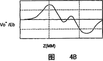
Fig. 4 A, Fig. 4 B, Fig. 4 C are depicted as 2 subdifferential curve charts of current potential on the Potential distribution, tubular axis of existing heavy caliber main lens and at the track of heavy caliber main lens inner edge bundle, in addition, Fig. 5 A, Fig. 5 B, Fig. 5 C are depicted as the Potential distribution of heavy caliber main lens of the present invention, and 2 subdifferential curve charts of current potential reach the track at heavy caliber main lens inner edge bundle on the tubular axis.In Fig. 4 A, Fig. 4 C and Fig. 5 B, Fig. 5 C, the 5th grid is equivalent to focusing electrode G5, and the 6th grid G 6 is equivalent to anode, configuration target GM between the 5th and the 6th grid G 5, the G6.
In existing heavy caliber main lens of Fig. 4 A and Fig. 5 A approximate representation and the heavy caliber main lens of the present invention, the Potential distribution that in this main lens, produces.From Fig. 4 A and Fig. 5 A as can be known, in the application's color picture tube, adjacent anode G6 and target GM are the shared long tubes of growing on the word order direction of three-beam electron-beam, about its opening opposing portion with the direction (vertical direction) of word order direction (horizontal direction) quadrature on opening diameter, be to set the diameter of anode openings littler than the diameter of target opening.
Adopt such structure, between mutually close anode G6 and target GM, form three-beam electron-beam shared, focus on and the relative multipole lens of dispersing in vertical direction in the horizontal direction relatively.Therefore, the electric field that is penetrated into target inside is released by the face relative with target of anode, thereby compares with existing electron gun, and it is close that the current potential of target inside becomes.Consequently, focusing electrode G5 compares with existing electrode structure with the lens between the anode G6 with lens and target GM between the target GM, is more prone to form continuous lens.In the past, for interconnecting, two lens that will form before and after the target become a continuous Large Aperture Lenses, the length L of target on the electron beam direction of advance is subjected to the restriction of the short diameter Dv (diameter on the vertical direction) of target front and back opening, promptly preferably satisfies
0.3≤Dv/L≤0.6
(the flat 11-131469 of the special hope of Japan Patent).
But, the structure of employing the invention described above, the current potential in the target becomes close as mentioned above, and two continuous lens before and after the target connect easily, can increase the length L of target on the electron beam direction of advance, and the connection of lens are not cut off.
Fig. 4 B and Fig. 5 B are the potential change (curves of Vo ") state that the current potential (Vo) on the picture tube tubular axis existing and of the present invention carries out 2 subdifferentials.The focal zone and the radiating area of the current potential 2 subdifferential curve representation heavy caliber main lenss on this tubular axis.That is, if 2 subdifferentials of current potential on the existing heavy caliber main lens tubular axis of next 4B with the aid of pictures, then can find, lens 2 subdifferentials of current potential on tubular axis that form are changed to radiating area along the electron beam direction of advance from focal zone, and radiating area and focal zone are alternately repeated.As a result, this existing Large Aperture Lenses become to have focus on-disperse-focus on-lens of disperse function.Making like this to disperse with focusing on the lens combination that replaces repeatedly to make the aberration of lens increase, is unfavorable therefore.Compare with it, picture tube of the present invention is changed to radiating area from focal zone in 2 subdifferentials of the current potential on the tubular axis on the electron beam direction of advance, some changes up and down slightly near the centre, but all is the variation at focal zone, and the result forms the lens that have only one group of focusing-disperse function.Consequently, compare with existing heavy caliber main lens, heavy caliber main lens of the present invention can prevent as far as possible that when increasing the target length L lens aberration from increasing.If observe current potential 2 subdifferentials of the present invention on tubular axis, just can find that radiating area sharply rises along tubular axis again.This with compared in the past, the projection (depression) that is mid portion increases the result of the lens effect of radiating area to focusing on a side shifting in order to obtain the lens balance.The so rapid rising of radiating area can be offset the aberration that produces at focal zone, and its result can think, is that the bore of lens becomes big.
Fig. 4 C and Fig. 5 C represent the limit beam trajectory of heavy caliber main lens existing and of the present invention.That is to say, existing electrode structure is in order to eliminate the halation component of limit bundle, three-beam electron-beam is focused on the phosphor screen, must be to middle Shu Fangxiang bending before injecting the heavy caliber main lens, for this reason, the center of limit Shu Tongkong, the secondary lens centre that for example center of the limit Shu Tongkong of the 2nd grid and the 3rd grid, or the 3rd, the 4th and the 5th grid constitutes is designed to off-centre.If as the former, in case Shu Tongkong center, the limit off-centre of the 2nd grid and the 3rd grid, although then bigger at the 2nd grid and the middle potential difference of the 3rd grid, opening diameter still is little, and therefore aberration takes place when limit Shu Xiangzhong Shu Fangxiang is crooked, and the limit beam distortion is remarkable.Again, the problem that produces under the situation of the secondary lens centre off-centre that the latter's the 3rd, the 4th and the 5th grid constitutes is, the shape of needed inner core pin must be very complicated when the electrode that constitutes electron gun was assembled, and is easy to generate error during assembling.
Compare with it, in the present invention, its heavy caliber main lens has the effect that actively makes limit Shu Xiangzhong Shu Fangxiang bending, therefore as long as made limit Shu Xiangzhong Shu Fangxiang slight curvature before the heavy caliber main lens is gone in the limit beam, does not perhaps need to make limit Shu Xiangzhong Shu Fangxiang bending.Therefore can reduce the aberration (or not producing) that produces when between the 2nd grid and the 3rd grid, making limit Shu Xiangzhong Shu Fangxiang crooked.So the shape of its advantage is the electrode that constitutes electron gun when being assembled needed inner core pin is complexity so just.
On the other hand, in the existing heavy caliber main lens, interelectrode opening shape is that section long on the horizontal direction is an oval in shape, therefore the aperture of lens on the vertical direction is obviously little than the aperture of lens on the horizontal direction, beam spot on the phosphor screen excessively focuses in vertical direction, and focuses on not enough in the horizontal direction.For this phenomenon is revised, electric field correction battery lead plate is installed in the position of drawing back from the opening of focusing electrode, the perforate formation of corresponding formations with three-beam electron-beam of this electric field correction battery lead plate is less in the horizontal direction and in vertical very long hole.The method of utilizing the hole diameter in the horizontal direction of the corresponding formation of handle like this to reduce with three-beam electron-beam, can be to the focusing on the horizontal direction focusing on the not enough and vertical direction excessively revise.But because the hole of corresponding formation with a three-beam electron-beam diameter in the horizontal direction reduces, therefore the problem that produces is, electron beam by the time be subjected to the influence of the local aberration component in hole, the lens electric field reaches in the horizontal direction on the electron beam direction of advance and expands as a result, forms the resulting effect of heavy caliber main lens originally and significantly reduces.Compare with it, in the present invention, have between anode G6 and the target GM for the shared relative lens component of dispersing in vertical direction, focusing in the horizontal direction of three-beam electron-beam, therefore the electric field correction battery lead plate of installing from the position that the opening of focusing electrode retreats, the hole diameter in the horizontal direction of its corresponding formation with three-beam electron-beam needn't be very little, from the electric field correction battery lead plate that install the position that the opening of focusing electrode retreats, the locality aberration component in the hole of its corresponding formation with three-beam electron-beam is alleviated.
Description of drawings
Fig. 1 is the summary section of general color picture tube.
Fig. 2 represents the halation state of existing colorful visualization tube edge bundle.
Fig. 3 A and Fig. 3 B summary represent that the main lens built-in potential distributes and lens state in the existing color picture tube.
Fig. 4 A is the potential image that is contained in the main lens part of the electron gun in the existing color picture tube.
Fig. 4 B represents current potential 2 subdifferentials on the axle of electron gun main lens part of existing color picture tube.
Fig. 4 C is the limit beam trajectory figure by the main lens part that is contained in the electron gun in the existing color picture tube.
Fig. 5 A is the main lens potential image partly of the color picture tube electron gun of one embodiment of the invention.
Fig. 5 B is current potential 2 subdifferentials on the color picture tube electron gun main lens part axle of one embodiment of the invention.
Fig. 5 C is the limit beam trajectory figure by the main lens part that is contained in color picture tube electron gun of the present invention.
Fig. 6 A and Fig. 6 B are the general section of structures of the color picture tube electron gun of one embodiment of the invention.
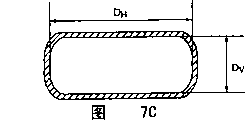
Fig. 7 A~Fig. 7 E is the shape profile of the employed electrode of electron gun of the color picture tube of one embodiment of the invention.
Embodiment
Fig. 6 A and Fig. 6 B are the electron gun general section of structures partly of the cathode ray tube device of one embodiment of the invention.In the electron gun shown in Fig. 6 A, heated filament (not shown) is equipped with in inside, three negative electrodes (KB), (KG), (KR), the 1st grid the 1, the 2nd grid the 2, the 3rd grid the 3, the 4th grid the 4, the 5th grid (focusing electrode) the 5, the 6th grid (target) the 6, the 7th electrode (anode) 7 and cup-shaped convergence electrode (convergencecup) CP that produce electron beam are according to this arranged in order, and it is fixing that these electrodes utilize insulator (not shown) to be supported.
Shown in Fig. 6 B, resistor 100 is set near electron gun, an end A of this resistor 100 is connected with the 7th electrode (anode) 7, and other end C is connected variable resistor other end ground connection with picture tube variable resistor outward.The intermediate point B of resistor 100 is connected with the 6th grid (target) 6, applies the voltage of lower than the anode voltage Eb that applies on the cup-shaped convergence electrode CP, higher than the focus voltage (Vf) of the medium potential that applies on the 5th grid (focusing electrode) 5 middle high potential.
The 1st grid 1 is lamellar electrode, and the 1st grid 1 is provided with 3 electron beam through-holes of minor diameter.The 2nd grid 2 is lamellar electrode too, also is provided with 3 electron beam through-holes of minor diameter.The 3rd grid 3 is combinations of a cup-shape electrode and slab electrode, is provided with diameter 3 electron beam through-holes bigger slightly than the electron beam through-hole of the 2nd grid 2 in the side near the 2nd grid 2, is provided with large diameter 3 electron beam through-holes in the side near the 4th grid 4.The 4th grid 4 is that two cup-shape electrode openings constitute relatively, is respectively equipped with large diameter 3 electron beam through-holes.The 5th grid (focusing electrode) 5 is by constituting by long two cup-shape electrodes 51, plate electrode 52 of direction and tubular electrode 53 with the shared opening of three-beam electron-beam shown in Fig. 7 A at electron beam, from seeing the 5th grid (focusing electrode) 5, then form the shape shown in Fig. 7 B near the 6th grid (target) side.Also have, the 6th grid (target) 6 is that the plate electrode 62 that two one of tubular electrode 61 sandwich with the shared opening of three-beam electron-beam shown in Fig. 7 A are provided with 3 electron beam through-holes constitutes, this electrode is seen or from the 7th electrode (anode) 7 one sides from the 5th grid (focusing electrode) 5 one sides, forms the shape shown in Fig. 7 B.And the 7th electrode (anode) the 7th has the tubular electrode 71 of the shared opening of three-beam electron-beam shown in Fig. 7 D, the plate electrode 72 that is provided with 3 electron beam through-holes sets gradually formation, see the 7th electrode (anode) 7 from the 6th grid (target) 6 one sides, form the shape shown in Fig. 7 E.
That is to say, suppose the opening diameter near the 7th electrode (anode) 7 one sides of the 6th grid (target) 6, in its horizontal diameter is DH, perpendicular diameter is DV, the opening diameter near the 6th grid (target) 6 one sides of the 7th electrode (anode) 7, its horizontal diameter is DH ', and perpendicular diameter is DV ', and at this moment its relation is decided to be:
DH≈DH’
DV>DV’
Utilize such structure, between adjacent the 7th electrode (anode) 7 and the 6th grid (target) 6, form for shared relative of three-beam electron-beam and focus in the horizontal direction, the multipole lens of dispersing in vertical direction, opening diameter on the vertical direction of the 7th electrode (anode) 7 is littler than the opening diameter of the 6th grid (target) 6 simultaneously, electric field to the internal penetration of the 6th grid (target) 6 is released by the part of the 7th electrode (anode) 7 and the 6th grid (target) 6 opposite faces, compare with existing electron gun, the built-in potential of the 6th grid (target) 6 is closeer.Therefore, the lens between lens between the 5th grid (focusing electrode) 5-the 6th grid (target) 6 and the 6th grid (target) 6-the 7th electrode (anode) 7 compared with the prior art, the easier continuous lens that is connected to form.
In the past, for former and later two lens the 6th grid (target) 6 connect, form continuous bigbore lens, the length L of the 6th grid (target) 6 on the electron beam direction of advance is subjected to the restriction of the short diameter Dv of the 6th grid (target) 6 front and back openings, and preferably Dv/L satisfies following formula (the special flat 11-131469 of hope of Japan Patent):
0.3≤Dv/L≤0.6
And employing the present invention, then the 6th grid (target) 6 former and later two continuous lens connect better, therefore, can increase the length L of the 6th grid (target) 6 on the electron beam direction of advance, and two lens do not block.
The effect of the fine connection of the 6th grid (target) 6 former and later two lens also can use current potential 2 subdifferentials on the tubular axis to be illustrated.Fig. 4 B and Fig. 5 B represent the curve of current potential 2 subdifferentials of picture tube existing and of the present invention on tubular axis.The focal zone and the radiating area of the current potential 2 subdifferential curve representation heavy caliber main lenss on this tubular axis.Current potential 2 subdifferentials in the existing heavy caliber main lens of observation Fig. 4 B on the tubular axis as can be seen, the lens that form change to radiating area from focal zone on the electron beam direction of advance in 2 subdifferentials of the current potential on the tubular axis, and near radiating area and alternately repetition of the focal zone centre, consequently, form the lens that focus on-disperse-focus on-disperse.Such focusing with disperse alternately repeated lens combination, the aberration of lens is increased, be unfavorable.In contrast to this, picture tube of the present invention changes to radiating area from focal zone in 2 subdifferentials of the current potential on the tubular axis on the electron beam direction of advance, have slightly up and down to change near the centre, but be the variation that takes place at focal zone fully, consequently, formation has only one group of lens that focus on-disperse.Therefore, heavy caliber main lens of the present invention can prevent as far as possible that when increasing the target length L lens aberration from increasing.If current potential 2 subdifferentials of picture tube of the present invention on tubular axis are observed, can see that radiating area sharply rises again.This compares with prior art, and the projection (depression) that is mid portion increases the result of the lens effect of radiating area to focusing on side shifting in order to obtain the lens balance.The so rapid rising of radiating area has the effect of counteracting at the aberration of focal zone generation, and its result can think, is that the bore of lens becomes big.
Again, in the present invention, such as following detailed description, in the past for the halation component of eliminating limit bundle and on phosphor screen three-beam electron-beam concentrate, the limit bundle must be to middle Shu Fangxiang bending before injecting the heavy caliber main lens, the center of limit Shu Tongkong, the center and the 3rd of the limit Shu Tongkong of the 2nd grid 2 and the 3rd grid 3 for example, the center of the secondary lens that the 4th and the 5th grid constitutes must be eccentric, if as the former, in case the center off-centre of the limit Shu Tongkong of the 2nd and the 3rd grid, then the problem of Chan Shenging is, though potential difference is big between the 2nd and the 3rd grid, but opening diameter is little, and therefore aberration takes place when limit Shu Xiangzhong Shu Fangxiang is crooked, and limit Shu Fasheng distorts significantly.Again, if as the latter, under the situation of the center off-centre of the secondary lens that the 3rd, the 4th and the 5th grid constitutes, then the problem of Chan Shenging is, the shape of needed inner core pin must be very complicated when the electrode that constitutes electron gun was assembled, easy generation error during assembling.And the multipole lens that the present invention disperses in vertical direction owing to form the shared relative focusing in the horizontal direction of three-beam electron-beam between adjacent the 7th electrode (anode) 7 and the 6th grid (target) 6, in the heavy caliber main lens, has the effect that actively makes limit Shu Xianzhong Shu Fangxiang bending, therefore as long as the limit bundle slightly to middle Shu Fangxiang bending (perhaps not needing bending), can alleviate the aberration (or with its elimination) that produces when making limit Shu Xiangzhong Shu Fangxiang crooked like this between the 2nd and the 3rd grid before injecting the heavy caliber main lens.So its advantage is that the shape of needed inner core pin just needn't be too complicated when the electrode of formation electron gun was assembled.
On the other hand, existing heavy caliber main lens is because the opening shape between the electrode is that the long section of horizontal direction is an oval in shape, therefore significantly the aperture of lens than horizontal direction is little for the aperture of lens of vertical direction, for the beam spot of revising on the phosphor screen excessively focuses on and the phenomenon of focusing deficiency in the horizontal direction in vertical direction, the hole that the electric field correction battery lead plate of installing in the position that the opening from the 5th grid (focusing electrode) retreats independently forms three-beam electron-beam is made in the horizontal direction little and hole that longitudinal direction is very long, excessive focusing on focusing on horizontal direction deficiency and the vertical direction is revised, simultaneously because the hole diameter in the horizontal direction that three-beam electron-beam is independently formed is less, cause electron beam by the time be subjected to the influence of the local aberration component of aperture portion.And in the present invention, because having shared relative of three-beam electron-beam between the 7th electrode (anode) 7 and the 6th grid (target) 6 disperses in vertical direction, the lens component of Ju Jiaoing in the horizontal direction, therefore the electric field correction battery lead plate of installing from the position that the opening of the 5th grid (focusing electrode) 5 retreats there is no need to do very for a short time to the hole diameter in the horizontal direction that three-beam electron-beam independently forms, the electric field correction battery lead plate of installing from the position that the opening of the 5th grid (focusing electrode) 5 retreats is alleviated the caused local aberration component in hole that three-beam electron-beam independently forms, and can realize the heavy caliber main lens.
As mentioned above, cathode ray tube of the present invention possesses: have the electron beam that forms and launch the three-beam electron-beam of word order configuration and form part and make this electron beam focus on the electron gun of the main lens on the phosphor screen, and produce and to make the level of this electron gun electrons emitted bundle on picture and the deflecting coil of the magnetic deflection field of vertical direction upper deflecting scanning, it is characterized in that
The described main focusing lens of described electron gun comprises the focusing electrode that applies medium focus voltage, apply the anode of high potential anode voltage, and be disposed at least one target between this focusing electrode and the anode, described target applies the focus voltage height than described medium potential, and the intermediate potential of the middle high potential lower than the anode voltage of described high potential, described intermediate potential is to utilize near be disposed at the electron gun resistor that the anode voltage of high potential is carried out dividing potential drop and the intermediate potential of the middle high potential that obtains
Mutually close anode and the peristome of target are to be respectively the shared long long tube on the word order direction of three-beam electron-beam, configuration is all worked to three-beam electron-beam between close mutually anode and the target, relative dispersing in vertical direction and the multipole lens of focusing in the horizontal direction.
Again, above-mentioned cathode ray tube device, it is characterized in that, mutually close described anode and the peristome of target are shared long long on the word order direction of three-beam electron-beam, this opening diameter in the direction vertical with the word order direction is set at, the diameter of anode openings is littler than the diameter of target opening, forms for the shared multipole lens of three-beam electron-beam.
Adopt such structure, it is shared to form three-beam electron-beam between close mutually anode and target, the multipole lens that focuses on relatively in the horizontal direction and disperse in vertical direction relatively, simultaneously, because anode opening diameter in vertical direction is littler than the opening diameter of target, the electric field that is penetrated into target inside is released by the face relative with target of anode, compare with existing electron gun, it is close that the current potential of target inside becomes, therefore focusing electrode is compared with existing electrode structure with the lens between the anode with lens and target between the target, is more prone to form continuous lens.Therefore, the connection of two continuous lenses of target front and back is not separated, thereby be connected to become a more bigbore main lens, and the length L of target on the electron beam direction of advance can be longer.
Again, in the present invention, the multipole lens that forms the shared relative focusing in the horizontal direction of three-beam electron-beam between mutually close the 7th electrode (anode) and the 6th grid (target) and disperse in vertical direction, the heavy caliber main lens has the effect that actively makes limit Shu Xiangzhong Shu Fangxiang bending, therefore as long as before the heavy caliber main lens is gone in the limit beam, make limit Shu Xiangzhong Shu Fangxiang slight curvature (perhaps not needing bending), so can be between the 2nd grid and the 3rd grid or the 3rd grid, the aberration that produces when the Shu Xiangzhong Shu Fangxiang bending of limit is reduced or do not produce aberration.So the shape of needed inner core pin just needn't be too complicated when the electrode of formation electron gun was assembled.
Also have, for the lens component that focuses in the horizontal direction having shared relative the dispersing in vertical direction of three-beam electron-beam between the 7th electrode (anode) 7 and the 6th grid (target) 6, in the position that the opening from the 5th grid (focusing electrode) 5 retreats electric field correction battery lead plate is installed, in the present invention, described electric field correction battery lead plate does not need very little to the hole diameter in the horizontal direction that three-beam electron-beam independently forms, thereby the hole that the electric field correction battery lead plate of installing from the position that the opening of the 5th grid (focusing electrode) 5 retreats independently forms three-beam electron-beam causes local aberration component to be alleviated, and can realize the heavy caliber main lens.
Claims (2)
1. a color picture tube possesses
Have and form and the electron beam of the three-beam electron-beam of emission word order forms part and make this electron beam focus on the electron gun of the main lens on the phosphor screen, and
Generation makes the level of this electron gun electrons emitted bundle on picture and the deflecting coil of the magnetic deflection field of vertical direction upper deflecting scanning, it is characterized in that,
The described main focusing lens of described electron gun comprises the focusing electrode that applies medium focus voltage, apply the anode of high potential anode voltage, and be disposed at least one target between this focusing electrode and the anode, described target applies the focus voltage height than described medium potential, and the intermediate potential of the middle high potential lower than the anode voltage of described high potential, described intermediate potential is to utilize near be disposed at the electron gun resistor that the anode voltage of high potential is carried out dividing potential drop and the intermediate potential of the middle high potential that obtains
Mutually close anode and the peristome of target are to be respectively the shared long cylinder on the word order direction of three-beam electron-beam, form between close mutually anode and the target three-beam electron-beam is all worked, relative dispersing in vertical direction and the multipole lens of focusing in the horizontal direction.
2. color picture tube according to claim 1, it is characterized in that, the close mutually described anode and the peristome of target are the shared long cylinders on the word order direction of three-beam electron-beam, this opening diameter in the direction vertical with the word order direction is set at, the diameter of anode openings is littler than the diameter of target opening, forms for the shared multipole lens of three-beam electron-beam.
Applications Claiming Priority (3)
| Application Number | Priority Date | Filing Date | Title |
|---|---|---|---|
| JP334599/1999 | 1999-11-25 | ||
| JP334599/99 | 1999-11-25 | ||
| JP33459999A JP3926953B2 (en) | 1999-11-25 | 1999-11-25 | Color picture tube |
Publications (2)
| Publication Number | Publication Date |
|---|---|
| CN1298195A CN1298195A (en) | 2001-06-06 |
| CN100339930C true CN100339930C (en) | 2007-09-26 |
Family
ID=18279203
Family Applications (1)
| Application Number | Title | Priority Date | Filing Date |
|---|---|---|---|
| CNB001352075A Expired - Fee Related CN100339930C (en) | 1999-11-25 | 2000-11-27 | Colour kinescope |
Country Status (5)
| Country | Link |
|---|---|
| US (1) | US6720726B1 (en) |
| JP (1) | JP3926953B2 (en) |
| KR (1) | KR100348694B1 (en) |
| CN (1) | CN100339930C (en) |
| TW (1) | TW495791B (en) |
Families Citing this family (3)
| Publication number | Priority date | Publication date | Assignee | Title |
|---|---|---|---|---|
| KR100447236B1 (en) * | 2002-02-28 | 2004-09-04 | 엘지.필립스디스플레이(주) | Electric Gun for Color CRT |
| JP2005222900A (en) | 2004-02-09 | 2005-08-18 | Matsushita Toshiba Picture Display Co Ltd | In-line type electron gun and color cathode-ray tube device using it |
| CN110534387A (en) * | 2019-09-06 | 2019-12-03 | 湖北大学 | A kind of ferroelectric ceramics boundling electronic emitter |
Citations (2)
| Publication number | Priority date | Publication date | Assignee | Title |
|---|---|---|---|---|
| US4712043A (en) * | 1984-02-20 | 1987-12-08 | Kabushiki Kaisha Toshiba | Electron gun with large aperture auxiliary electrode |
| CN1182278A (en) * | 1996-10-14 | 1998-05-20 | 株式会社日立制作所 | Color cathode ray tube having small neck diameter |
Family Cites Families (12)
| Publication number | Priority date | Publication date | Assignee | Title |
|---|---|---|---|---|
| US2988658A (en) * | 1959-07-02 | 1961-06-13 | Tung Sol Electric Inc | Electron gun for cathode ray tube |
| JP2693470B2 (en) * | 1988-03-16 | 1997-12-24 | 株式会社東芝 | Color picture tube |
| JPH06251722A (en) * | 1993-02-24 | 1994-09-09 | Hitachi Ltd | Cathode-ray tube |
| JP3324282B2 (en) | 1994-07-11 | 2002-09-17 | 松下電器産業株式会社 | Color picture tube equipment |
| JPH09190774A (en) * | 1996-01-10 | 1997-07-22 | Hitachi Ltd | Color cathode-ray tube |
| JPH09320485A (en) | 1996-03-26 | 1997-12-12 | Sony Corp | Color cathode-ray tube |
| JP3655440B2 (en) * | 1997-08-05 | 2005-06-02 | 松下電器産業株式会社 | Color picture tube |
| JPH11144641A (en) * | 1997-09-05 | 1999-05-28 | Hitachi Ltd | Color cathode-ray tube |
| TW392191B (en) * | 1997-10-30 | 2000-06-01 | Toshiba Corp | Color cathode ray tube apparatus |
| KR100311475B1 (en) * | 1999-06-11 | 2001-10-17 | 구자홍 | structure for electron gun in color cathod ray tube |
| KR20010018138A (en) * | 1999-08-17 | 2001-03-05 | 구자홍 | electron gun for color cathode ray tube |
| JP2001093436A (en) * | 1999-09-22 | 2001-04-06 | Hitachi Ltd | Color cathode-ray tube |
-
1999
- 1999-11-25 JP JP33459999A patent/JP3926953B2/en not_active Expired - Fee Related
-
2000
- 2000-11-17 TW TW089124430A patent/TW495791B/en not_active IP Right Cessation
- 2000-11-23 KR KR1020000069818A patent/KR100348694B1/en not_active IP Right Cessation
- 2000-11-24 US US09/718,484 patent/US6720726B1/en not_active Expired - Fee Related
- 2000-11-27 CN CNB001352075A patent/CN100339930C/en not_active Expired - Fee Related
Patent Citations (2)
| Publication number | Priority date | Publication date | Assignee | Title |
|---|---|---|---|---|
| US4712043A (en) * | 1984-02-20 | 1987-12-08 | Kabushiki Kaisha Toshiba | Electron gun with large aperture auxiliary electrode |
| CN1182278A (en) * | 1996-10-14 | 1998-05-20 | 株式会社日立制作所 | Color cathode ray tube having small neck diameter |
Also Published As
| Publication number | Publication date |
|---|---|
| CN1298195A (en) | 2001-06-06 |
| JP2001155656A (en) | 2001-06-08 |
| KR100348694B1 (en) | 2002-08-13 |
| KR20010051890A (en) | 2001-06-25 |
| TW495791B (en) | 2002-07-21 |
| US6720726B1 (en) | 2004-04-13 |
| JP3926953B2 (en) | 2007-06-06 |
Similar Documents
| Publication | Publication Date | Title |
|---|---|---|
| CN1027941C (en) | Cathode ray tube | |
| CN1134814C (en) | Color cathode ray tube having a low dynamic focus voltage | |
| CN1050439C (en) | Color braun tube apparatus | |
| CN1041243A (en) | The electron gun of chromoscope | |
| CN1034287A (en) | Colour display tube, deflection system and electron gun | |
| CN1155046C (en) | Cathode-ray tube | |
| CN1108427A (en) | Twin-convex electron gun | |
| CN100339930C (en) | Colour kinescope | |
| CN1097840C (en) | Dynamic 4 polar electrode system in pre-focusing electrode in electron gun for color cathode ray tube | |
| CN1040925C (en) | Colour display tube device | |
| CN1057636C (en) | Electron gun for color cathode ray tube | |
| CN1259755A (en) | Dynamic focusing electron gun of color cathode-ray tube | |
| CN87100733A (en) | Electron gun for color picture tube | |
| CN1459818A (en) | Electron gun for cathode-ray tube | |
| CN1084927C (en) | Electronic gun for color cathode ray tube | |
| CN1165069C (en) | Cathode-ray tube device | |
| CN1320591C (en) | Color cathode ray tube apparatus | |
| CN1130302A (en) | Colour display system by using quadrupole lens | |
| CN1296960C (en) | In-line electron gun and colour kinescope utilizing it | |
| CN1207751C (en) | Electron gun for CRT | |
| CN100341104C (en) | Color braun tube apparatus | |
| CN1165948C (en) | Cathode ray tube equipment | |
| CN1201367C (en) | Color cathode-ray tube apparatus | |
| CN1059051C (en) | Electron gun body for a color cathode ray tube | |
| CN1244130C (en) | Electronic gun of colour cathode ray tube |
Legal Events
| Date | Code | Title | Description |
|---|---|---|---|
| C10 | Entry into substantive examination | ||
| SE01 | Entry into force of request for substantive examination | ||
| C06 | Publication | ||
| PB01 | Publication | ||
| C14 | Grant of patent or utility model | ||
| GR01 | Patent grant | ||
| C19 | Lapse of patent right due to non-payment of the annual fee | ||
| CF01 | Termination of patent right due to non-payment of annual fee |