CN100339322C - Method and apparatus for producing glass blocks - Google Patents
Method and apparatus for producing glass blocks Download PDFInfo
- Publication number
- CN100339322C CN100339322C CNB011418737A CN01141873A CN100339322C CN 100339322 C CN100339322 C CN 100339322C CN B011418737 A CNB011418737 A CN B011418737A CN 01141873 A CN01141873 A CN 01141873A CN 100339322 C CN100339322 C CN 100339322C
- Authority
- CN
- China
- Prior art keywords
- glass
- mould
- melten glass
- gas
- melten
- Prior art date
- Legal status (The legal status is an assumption and is not a legal conclusion. Google has not performed a legal analysis and makes no representation as to the accuracy of the status listed.)
- Expired - Fee Related
Links
Images


Classifications
-
- C—CHEMISTRY; METALLURGY
- C03—GLASS; MINERAL OR SLAG WOOL
- C03B—MANUFACTURE, SHAPING, OR SUPPLEMENTARY PROCESSES
- C03B40/00—Preventing adhesion between glass and glass or between glass and the means used to shape it, hold it or support it
- C03B40/04—Preventing adhesion between glass and glass or between glass and the means used to shape it, hold it or support it using gas
-
- C—CHEMISTRY; METALLURGY
- C03—GLASS; MINERAL OR SLAG WOOL
- C03B—MANUFACTURE, SHAPING, OR SUPPLEMENTARY PROCESSES
- C03B19/00—Other methods of shaping glass
- C03B19/02—Other methods of shaping glass by casting molten glass, e.g. injection moulding
-
- C—CHEMISTRY; METALLURGY
- C03—GLASS; MINERAL OR SLAG WOOL
- C03B—MANUFACTURE, SHAPING, OR SUPPLEMENTARY PROCESSES
- C03B7/00—Distributors for the molten glass; Means for taking-off charges of molten glass; Producing the gob, e.g. controlling the gob shape, weight or delivery tact
- C03B7/10—Cutting-off or severing the glass flow with the aid of knives or scissors or non-contacting cutting means, e.g. a gas jet; Construction of the blades used
- C03B7/12—Cutting-off or severing a free-hanging glass stream, e.g. by the combination of gravity and surface tension forces
-
- Y—GENERAL TAGGING OF NEW TECHNOLOGICAL DEVELOPMENTS; GENERAL TAGGING OF CROSS-SECTIONAL TECHNOLOGIES SPANNING OVER SEVERAL SECTIONS OF THE IPC; TECHNICAL SUBJECTS COVERED BY FORMER USPC CROSS-REFERENCE ART COLLECTIONS [XRACs] AND DIGESTS
- Y02—TECHNOLOGIES OR APPLICATIONS FOR MITIGATION OR ADAPTATION AGAINST CLIMATE CHANGE
- Y02P—CLIMATE CHANGE MITIGATION TECHNOLOGIES IN THE PRODUCTION OR PROCESSING OF GOODS
- Y02P40/00—Technologies relating to the processing of minerals
- Y02P40/50—Glass production, e.g. reusing waste heat during processing or shaping
- Y02P40/57—Improving the yield, e-g- reduction of reject rates
Abstract
In a method of manufacturing a glass gob, a down-flowing molten glass is received on a molding die. The molding die is moved down at a speed higher than a down-flowing speed of the molten glass so as to cut the molten glass. The molten glass is remained with a predetermined weight on the molding die. The molten glass is sprayed with gas in order to form the glass gob under such a condition that the molten glass is floated or slightly floated. The receiving step is carried out by spraying the molten glass with gas having a flow rate lower than the gas used in the spraying step, or the receiving step is carried out without performing the gas spraying.
Description
Technical field
The present invention relates generally to a kind of method and apparatus that is used for having the glass block of predetermined weight with the melten glass manufacturing.In addition, the invention still further relates to a kind of method that is used for making the molded glass product by reheat and press-molding glass piece.Also have, the invention still further relates to by grinding or polishing and polish the method that this molded glass product is made Optical devices or element.
Background technology
About making method, a kind of known RP (reheat/pressing mold) method is arranged such as the molded glass product of opticglass device or element.This RP method is, a glass block with predetermined weight is heated to can carries out the preset temperature that pressing mold is handled, and handles thereby carry out pressing mold, and the glass block of reheat is carried out pressing mold.Will normally become the polylith sheet glass with the die material that the RP method is handled, then this sheet glass be obtained so that handle its surface through coarse polished finish (being called as rotary drum grinding barrel grinding) by cutting glass plate.On the other hand, become in the process of the polylith sheet glass that the pressing mold that will carry out the back handles at cutting glass plate, the weight of wanting to make all sheet glass all have homogeneous is very difficult, and therefore the very unfavorable sheet glass that will make has different weight each other.So, all have the weight of homogeneous in order to guarantee all sheet glass, need to rely on the method for rotary drum grinding to remove a large amount of glass materials.
In order to solve the problem of above-mentioned so-called weight inequality, applicant of the present invention has recommended a kind of improved method that moves down cutting that is called as in its previous patent application, it needs the melten glass of a certain amount of (predetermined amount) will be poured in the mould (this melten glass will form die material), but does not comprise the cutting process (Japanese unexamined patent publication number 2-34525) that sheet glass is cut into many sheet glass.With this cutting process that moves down, at first, a certain amount of melten glass is introduced in the mould.Then, the movably parts of each mould move down to be higher than the mobile speed of melten glass.Adopt this method, each molten glass flow is cut into divided portion, thereby the melten glass of remaining a certain amount of (predetermined amount) in each mould then can will be as the glass block of die material to produce the back by refrigerative mode step by step, thereby acquisition has the glass block of different shape.Usually, use the molding equipment that moves down cutting process will dispose a plurality of moulds, thereby these melten glass can be encased in these moulds in succession, produce glass block thus continuously.
Yet traditional the moving down in the cutting process of Tao Luning in the above because the melten glass that is encased in the mould contacts with the surface of mould, need be avoided occurring such as perforation and these defectives of crack on the surface of molded glass block., move down in use under the situation of cutting process for this reason, need provide such as unsteady gases such as nitrogen or certain gases, make this unsteady gas by being formed at a plurality of discharge orifices of molded surface at the molded surface of mould.Adopt this mode, can keep melten glass to be in and float or slight afloat, this makes and melten glass can be kept minimum contacting with the molded surface of mould.In order to satisfy these demands, traditional cutting process that moves down is modified into: be branched into several strands of air-flows from the showy gas of source of the gas supply, thereby supply each mould, the amount of per share air-flow needs enough, makes it possible to have sufficient contact between the molded surface of melten glass and each mould.In fact, the discharge orifice that per share air communication is crossed the molded surface that is formed at each mould outwards discharges, and arrives molded surface up to take out melten glass from mould during from melten glass, and this air-flow discharging is carried out continuously.Particularly, melten glass supply process (being known as casting in the following description sometimes handles), because melten glass very likely contacts with the molded surface of mould, so the flow velocity of per share unsteady gas increases, this will be considered to and can solve the above problems effectively.
Yet, under the situation of flow velocity according to aforementioned requirement setting of the gas that floats, during the casting cycle of casting melten glass, when the moment that melten glass contacts with mould, it is very violent that the behavior of melten glass becomes, and will cause some latent defects (changing and striped as pleat) thus.In order to address this problem, inventor of the present invention need control the flow velocity of the gas that floats, and when use is above-mentioned when moving down cutting process, this control must be satisfied two kinds of mobile needs, to stablize molded state.
(1) when using mould to carry out melten glass molded, it is erratic to be supplied to the flow velocity of the unsteady gas of each mould not have, and the flow velocity of per share unsteady gas should be enough to guarantee that melten glass floats off each mould.
(2) during the casting of melten glass, the flow velocity of per share unsteady gas should be set, make that melten glass should not have unsettled behavior in the moment of a certain amount of melten glass contact mould.
Summary of the invention
Therefore, an object of the present invention is to provide the method and apparatus that is used to make melten glass, this method can correctly be provided for carrying out the flow velocity of the unsteady gas of stable unsteady molding process, obtain stable casting state, thereby can produce the glass block of inequality with high-quality and minimizing weight.
Another object of the present invention provides a kind of manufacture method of melten glass product, and wherein aforementioned melten glass at first is heated, and stands pressing mold then and handles to produce molded glassy product.A further object of the invention provides a kind of optical element manufacture method, and wherein, aforementioned glass molding product is ground and polishes, thereby produces various optical elements.
To achieve these goals, glass block manufacturing method of the present invention comprises:
The first step, mould receive defluent melten glass;
Second step moved down mould to be higher than the dirty speed of melten glass, thereby the cutting melten glass becomes separated portions, to stay the melten glass of predetermined weight in each mould;
The 3rd step, with this melten glass of air-stream spraying with float at melten glass or the slight state that floats under form glass block.
Say that meticulously the first step is to carry out with having under the air-stream spraying melten glass that is lower than used gas velocity of the 3rd step, perhaps the first step is to carry out under the situation of not carrying out gas atomization.
According to the test that inventor of the present invention carried out, even the temperature of melten glass is higher relatively during casting, even and the surface shape of the mould that contacts with melten glass is transformed into the shape of melten glass, very clear in this case, if duration of contact is shorter, if and melten glass floats, since its surface tension, the original-shape that the shape of melten glass can be recovered soon.Therefore, the method according to this invention, under the situation that the gas velocity of the above-mentioned the first step reduces, melten glass will contact with mould during casting.Yet if the gas velocity of back increases, melten glass can float or slightly float, thereby makes the surface recovery of melten glass arrive virgin state.On the other hand, if the gas flow rate during casting reduces, even being reduced to zero, this can suppress the violent behavior of melten glass, thereby can produce the glass block any latent defect of fold that causes under the violent behavior situation of melten glass and striped.
At this moment, begin to be set to one second or shorter from the first step to the timed interval of the 3rd step beginning.
The gas velocity of the first step is preferably 5% to 20% of the 3rd gas velocity that goes on foot, and more preferably 5%-15% most preferably is 7%-14%.
Specifically, preferably the first step is performed such, that is, what accept in the mould is the melten glass of 30 to 2 pool viscosity.
In addition, method of the present invention also comprises when the temperature of glass block is equal to or less than the transition point of glass, takes out the 4th step of glass block from mould.
In addition, the invention provides a kind of manufacture method of molded glass product, it is characterized in that at first being heated, stand pressing mold then and handle, thereby produce the molded glass product according to the glass block of preceding method manufacturing.
In addition, the present invention relates to a kind of optical element (device) manufacture method, it is characterized in that preceding method is used to make optical element blank, this blank is ground (grinding) and polishing then, thereby produces optical element (device).
In addition, the present invention also provides a kind of glass block producing apparatus, and it comprises mould, and they have the molded surface that is formed with many gas orifices; Be used to supply the melten glass feeding mechanism of melten glass to mould; Can move down mould to be higher than the dirty speed of melten glass, thereby cut the mould lifting/lowering running gear that melten glass becomes separated portions and stay the melten glass of predetermined weight in each mould; Be used to supply the gas supply device of the gas that will discharge from the discharge orifice of mould; Be used to regulate from the setting device of the flow velocity of the air-flow of the discharge orifice discharging of each mould; Described setting device can be when molten glass flow be provided the flow velocity of adjustments of gas to mould, thereby make gas flow rate in this time be lower than the another kind of gas velocity when a certain amount of melten glass is left in the mould.
In this case, the gas flow rate setting device comprises: allow from the gas of gas source supply by not being that the gas that other perforate of the perforate on the mould disengages flows into path; Be used for when mould is risen by mould lifting/lowering running gear, open gas and flow into path and when mould is fallen by mould lifting/lowering running gear, close the inflow gas opening/closing device that gas flows into path;
Description of drawings
Fig. 1 is the side-view that shows the equipment of making glass block;
Fig. 2 is the orthographic plan of this glass block producing apparatus;
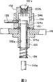
The side cross-sectional view of the mould of Fig. 3 when to be the moulding part that shows it about its molded base move down;
Fig. 4 is the side cross-sectional view that shows the mould when moving on its molded base of moulding part about it;
Fig. 5 shows the orthographic plan that is formed at the molded surface gas orifice array of mould according to an embodiment of the invention;
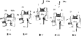
Fig. 6 A is to show according to an embodiment of the inventionly to be used to move down cutting method with the rendering of supply melten glass to the program of mould to 6E.
Concrete embodiment
(being used to make the equipment of glass block)
Below, the embodiment is with reference to the accompanying drawings described the present invention.
As depicted in figs. 1 and 2, the glass block producing apparatus is equipped with a plurality of moulds on a rotating disk.When the melten glass of a certain amount of (predetermined amount) is poured in the mould in succession, just might produce a large amount of glass block continuously.
As depicted in figs. 1 and 2, glass block producing apparatus 100 comprises a plurality of moulds 102, each mould at first accepts to have a certain amount of melten glass of predetermined viscosity, under the condition that melten glass floats or slightly floats, carry out mold treatment then, be used to supply the melten glass supply part 104 of a certain amount of melten glass to each mould 102; For each mould provide to support corresponding a plurality of mold bases 106 of these moulds; Can transmit the mould transfer member 108 of mould in succession; Mould lifting/lowering drive element 110 at position (back abbreviates casting position A as) a plurality of moulds of vertical shifting of the melten glass of accepting to provide is provided; Be used for cooling off step by step the process furnace 112 of fused glass block; Be used for discharging the releasing device 114 of refrigerative glass block step by step from mould.
The melten glass supply part is positioned at casting position A, and molten glass flow (do not show, but fuse in calciner) flow in the mould 102 by spout 104a.The spout 104a of melten glass supply part is by a temperature-control device (not shown), thereby molten glass flow can be controlled to predetermined viscosity when flowing out.Rely on this temperature control, can guarantee the suitable control of the productivity of glass block.Here, as in the preferred embodiment, aforementioned temperature control is carried out in such a way, makes the viscosity of melten glass of spout 104a can be controlled in 30 to 2 pools, is preferably 20 to 5 pools.
When rotating disk 116 rotated by mould transfer member 108, each mould 102 can be moved to casting position A.When arriving casting position, control each mould and pause a very short time to accept the melten glass of predetermined amount.After having accepted melten glass, mould will be removed from casting position.That is, mould transfer member 108 is periodically driven by direct CD-ROM drive motor, and in the mode that rotating disk 116 can rotate and stop to hocket, each only rotates and continues (this can be known as intermittently indicating mode) at a predetermined angle.In this way, when rotating disk 116 so that intermittence, being rotated property of indicating mode ground drove, a mould 102 that is mounted with the melten glass of predetermined amount will be removed from casting position A, simultaneously, and immediately following being moved to casting position A at thereafter another mould 102 (not loading melten glass).By repeating these steps, can be from the continuous effusive molten glass material of mouth 104a of melten glass supply part without any being loaded in succession the mould 102 with pausing.Yet, will describe in detail as the back, be used for process and can move down cutting method by use and carry out from melten glass supply part 104 supply molten glass material to mould 102.
As shown in Figure 1, mould lifting/lowering drive element 110 is positioned at casting position A, just in time is positioned at mold base 106 belows that are fixed on rotating disk 116 peripheries.By this way, when supplying melten glass to mould 102 from melten glass supply part 104, mould lifting/lowering drive element 110 will be actuated to the mould 102 that vertical shifting is positioned at casting position A.Yet configuration is used for the mechanism back of vertical shifting mould 102 and will describes in detail.
As shown in Figure 2, process furnace 112 is placed along the motion track that is installed in the mould 102 on the rotating disk 116, extends to glass block extracting position (back abbreviates extracting position B as) from casting position A, also extends to casting position A from extracting position B.In addition, as shown in Figure 1, process furnace 112 is installed into and can covers mould 102 from the top of mould.By this way, the mould 102 that passes process furnace 112 can be comprised in the interior heater heats of process furnace, and molten glass material in the mould 102 of packing into and the higher temperature higher than Heating temperature are cooled off step by step.Temperature in process furnace 112 preferably is arranged on 350 to 400 ℃ scope, therefore, when they when casting position A moves to extracting position B, the melten glass that are loaded in these moulds 102 are cooled off step by step, so produce required glass block.In addition, another process furnace 112 is between extracting position B and casting position A, so that carry out heat treated and heat maintenance processing, thereby the temperature that guarantees mould (fused glass block takes out) is unlikely to too low.
A withdrawing device 114 is positioned at extracting position B, and this withdrawing device is used for taking out glass block (its temperature has become and has been equal to or less than glass transition point Tg) from mould 102.That is, withdrawing device 114 configurations are used for spray gas to the glass block (from the side in the face of mould 102) that is loaded in the mould, drop on the collection device 120 that is positioned at withdrawing device 114 opposites thereby order about glass block.
Below, will describe the structure of mold base 106 and mould 102 with reference to figure 3 and Fig. 4 in detail, they two all be positioned on the rotating disk 116.
Specifically, Fig. 3 has shown the state that mould 102 has reduced with respect to mold base 106, and Fig. 4 shows another state that mould 102 has raise with respect to mold base 106.As shown in these figures, each mold base 106 all has a base component 122 that is fixed on the rotating disk 116, also has a movable part 124 of can installation mold 102 and moving in vertical direction with respect to base component 122.In detail, base component 122 is formed at its center, have one can be slidably the fixing centre hole 122a of the spindle unit 124a of movable part 124.In fact, spindle unit 124a outwards protrudes from the bottom of centre hole 122a.The bottom part of the projection of spindle unit 124a twines with spring 126.By this way, just may guarantee that an effective function power actuates movable part 124 consistently downwards.
Mould lifting/lowering drive element 110 is configured in the below of mold base 106, is positioned at melten glass casting position A.The drive shaft 110a of drive element extends up to the bottom of the spindle unit 124a of movable part.In the casting cycle of melten glass, mould lifting/lowering drive element 110 is driven, thereby drive shaft is risen in mode shown in Figure 4.At this moment, the movable part 124 of mold base is owing to the elastic force effect of spring 126 is risen.As a result, mould 102 is lifted to the position near the outlet 104a of melten glass supply part, thereby makes melten glass be supplied in the mould.
In fact, the glass block producing apparatus 100 of present embodiment uses a kind of cutting method that moves down, and this is believed to produce effectively the glass block that respectively has predetermined weight.As discussed above, in case mould 102 is moved to casting position A, mould lifting/lowering drive element 110 will bring into operation, and make its drive shaft 110a can upwards oppress the movable part 124 of mold base 106.If there be not upwarding pressure of drive shaft 110a generation here, the elastic force of spring 126 will impel displaceable member 124 downwards, and it is remained on a lower position.Here, moved to move up owing to start axle 110a, movable part 124 will be pressed towards the top owing to the elastic force of spring 126.As a result, movable part 124 and mould 102 all are raised, and make molded surface 102a near spout 104a.Preferably 5 to 10 millimeters of spacings between the upper end of the front end of spout 104a and mould 102.
In this case, air-flow (being used for floating or slightly floating glass block) is provided for each that is installed in 36 moulds 102 on the rotating disk 116 by mold base 106.Be branched into a lot of strands of air-flows from the gas of source of the gas (not shown) supply, thereby flow to a plurality of air flues 128 that link to each other with mould 102.By this way, can make the gas velocity that flows to a mould equal to flow to the gas velocity of another mould, guarantee that thus all gas velocities that flow to each mould are all consistent.At this moment, as shown in Figure 3, can be introduced in each space 124b in the movable part 124 that is formed at each mold base by air flue 128 from the air-flow of source of the gas supply, and spray by a plurality of discharge orifice 102b that link to each other with the molded surface that is formed at each mould 102.Gas by discharge orifice 102b ejection is caused to the glass block spraying of staying die surface, thereby glass block is floated or slight floating.Here, be used for floating or slightly the float gas of glass block can be rare gas element such as air or nitrogen.In addition, it also can be to use the mixed gas that comprises air and nitrogen.
As shown in Figure 5, a plurality of gas orifice 102b are placed in the central zone of molded surface 102a, in circumferential direction each interval equidistance, so that might float or slightly float (with a kind of stable manner) is carried in the glass block of molded surface 102a.Yet gas orifice 102b does not need to be limited to certain number, and in fact it also can only form and use a gas orifice.In addition, molded surface can constitute with porous material.As a result, the many tiny hole of porous material can be used as gas orifice.Yet, in order to float or slightly float melten glass or glass block (with a kind of stable manner), can preferred a plurality of gas orifice 102b be symmetrically distributed around the axis of mould.More preferably a plurality of gas orifice 102b distribute equably with the spacing that equates.
The movable part 124 of each mold base 106 is by a leakage hole 124c who is used for space 124b gas leakage internally.In addition, be connected with packing ring 130, in such a way, promptly make packing ring 130 be positioned at position in the face of leakage hole at the base component 122 of each mold base 106.Under the situation that movable part 124 is actuated downwards owing to the elastic force of spring 126, promptly work as a certain amount of melten glass and be supplied to mould 102, mould is moved through process furnace 112 then, thereby make glass block be formed at molded surface, leakage hole 124c will be configured in packing ring 130 sealings on the base component 122.By this way, the gas that is provided to whole amounts of internal space 124b through air flue 128 can be shifted to gas orifice 102b, is discharged into molded surface 102a then.On the other hand, as shown in Figure 4, when movable part 124 be pressed towards the top and mould 102 be positioned at casting position A, in case molded surface receives melten glass, leakage hole 124c will open, so that gas spills from leakage hole, adopt mode like this to make and reduce from the gas flow rate of gas orifice 102b ejection.Therefore, the equipment of present embodiment is not only simple in structure, and can reduce gas velocity by gas orifice 102b ejection (this reduction by means of moving up of mould and very effective) very effectively.But this function unit that is used for the pilot-gas flow velocity should not be limited to above-mentioned example, and may utilize electrical signal pilot-gas flow velocity to adjust valve yet, makes the driving that responds drive shaft operate and reduces this gas supply.
As shown in Figure 6, when mould was arranged in casting position A and this mould lifting/lowering drive part 110 and is in its driving mechanism (driving movement), molded (molding) surface of mould 102 can be near spout 104a.Thereby, molten glass flow G is provided can for molded surface 102a.(referring to Fig. 6 A to 6C).Then, after through a predetermined amount of time, discharge the last moving mechanism (working) of mould by mould lifting/lowering drive part 110.Therefore, the elastic force of the spring in the mold base 126 can cause moveable part 124 at once, press to descending direction with the dirty fast speed than melten glass.In this case, mould 102 also separates with spout 104a, and is reduced to its original height (original position before rising) fast thereon.Here, though before mould 102 moves down, support this support of the very fast release of quick reduction meeting of mould 102 by mould 102 from the low side of the effusive melten glass G of spout 104a.Therefore, this melten glass will be cut into divided portion in the low side g of this melten glass and a position between the spout 104a.In this manner, because this moves down patterning method and utilizes the own wt of this melten glass to realize this cutting action, and need not any cutter arrangement, so on this melten glass, stay any cutting vestige (, then can on this melten glass, stay the cutting vestige) hardly if use cutter to realize this cutting.In addition, when a large amount of melten glass moved to mould 102,102 on mould can move in vertical direction.Therefore, when melten glass 8 is cut into two portions, hardly can be at the molded described cut channel of formation on glass.
By means of the above-mentioned patterning method that moves down, owing to can produce a constant time period, it starts from the moment that mould 102 is accepted melten glass, ends at the moment that mould moves down, and that is to say can be by means of the time of mould lifting/lowering drive part 110 these melten glass of Cutting Control.Here, when this melten glass offered mould, leakage hole was opened.Therefore, the flow velocity from molded surface 102a effluent air will become very little.On the other hand, in case the rising of mould 102a is disengaged, the movable part 124 of mold base is got back to original height, and leakage hole 124 will be sealed by packing ring 130 once more.As a result, will get back to original gas flow rate (before mould rises) from the flow velocity of discharge orifice 102b emission gases.In fact, will be set to enough showy or slight floating by the gas purging amount of discharge orifice 102b and receive the value of the melten glass in the mould.
Yet when mould 102 during near spout 104a, that is, the gas emissions by discharge orifice 102b during the melten glass casting will reduce (gas flow rate also becomes zero).Here, if gas emissions does not reduce during the melten glass casting, because the low side (it does not also reach predetermined weight) that upwards pressure and to be applied to melten glass that the gas that discharges from gas discharge hole 102b produces.As a result, the vibrations that the low side of melten glass will occur not expecting in a kind of violent mode, cause melten glass moistening the front end of spout.As a result, this will be difficult to guarantee that the internal structure of each fused glass block has good quality (because gauffer and striped will take place), the feasible phenomenon that can not avoid forming the glass block with singular configuration and irregular weight.For fear of all these problems, the invention is characterized in the free air delivery of minimizing during the melten glass casting, thereby stablize melten glass, therefore can guarantee that the internal structure of each fused glass block has good quality, to avoid or to alleviate at least the phenomenon generation of glass block with singular configuration and irregular weight.
Preferably, (molten glass flow is caused the molded surface 102a that at first touches mould to a process, rely on the rapid shifting movement down of mould to cut into two portions then) should only in one second, finish, more preferably, this process should only be finished in 0.8 second.Although this is that the free air delivery of minimizing makes and might limit in top time to one in the extremely short period owing to make melten glass touch the molded surface 102a of mould.By this way, because melten glass (just flowing out) only has very low viscosity,, then can keep this low viscosity from mouth if said process is finished in a short period of time.Therefore, in the process of back, be in the showy or slight process of floating of melten glass, can make the temperature (its temperature because with contacting of molded surface part reduce) of glass surface equal not contact the temperature of the glass surface of molded surface, thereby make it can avoid in glass block, forming perforation or crack fully.
Yet, in above-mentioned glass block forming process (wherein forming glass block), can do suitable adjustment according to the weight of each glass block by the free air delivery of each mould by the melten glass that cools off step by step in mould 102.For example, this free air delivery can be adjusted to 0.5 liter of per minute.In addition, in above-mentioned casting cycle, the free air delivery by each mould preferably is set to 5 to 20% of above-mentioned free air delivery (in melten glass cooling period step by step), and more preferably 5 to 15%, most preferably be 7 to 14%.
When using above-mentioned glass block producing apparatus, need at full speed move moulds 102, thereby improved the productivity of making glass block, and assurance is caught accurately with the mould that constant speed continuous effusive melten glass from mouth can be moved to casting position in succession.For this reason, require rotating disk 116 to make, and each mould is to be made of carbon material, thereby makes the very light in weight of these parts with aluminium alloy.Here, carbon material must be able to not melt in melten glass, but must be in light weight and have a high strength.In addition, needing rotating disk 116 can be driven directly motor drives rotatably.
In fact, the molded surface 102a of each mould 102 forms a concave surface.In use, molded surface is suitable for limiting the outer dia (observing from orthographic plan) of fused glass block.For example, when producing a die material and be used to form the lens blank that respectively has near finished product, this molded surface will can not limit the surface tissue (being the cross section of melten glass) corresponding to the major surfaces of lens.That is, although each mould can limit the weight of each glass block and its external diameter, it does not limit the cross section of each glass block.Therefore, the glass block that obtains with aforesaid method can be used as die material, and becomes very soft through heat-treated up to it, and the viscosity that has is 10
4To 10
6Pool stands pressing mold then and handles, thereby can greatly change the shape of each glass block, and making does not need to form according to the shape of final compression-moulded product (in the step of making glass block) cross section of each glass block.
(used glass)
The glass block that uses aforesaid device production is used as die material to be used for making by pressing mold the accurate pressing mold process of the finished product.In addition, identical glass block also can be used as die material in reheat/process of lapping, and the surface of the moulded product that obtains by reheat and pressing mold in reheat/pressing mold process is polished and polishes, thereby produces finished product.When preparation was used for the material of precision press-molding, preferably using its glass transition point Tg was 580 ℃ glass material.This is because this glass material can have a low relatively temperature as mould temperature, also since this glass material not can with the compacting tool set fusion.
Table 1 and table 2 are presented at can be from the top continuous effusive molten state of spout, and can not lose the transparency of expectation and make some optical materials of glass block.
Table 1
| Preferred glass | The composition of preferred glass | More preferably glass | Glass transition n point (℃) | Corresponding to 30-2 pool (℃) temperature of viscosity |
| SiO 2-TiO 2Opticglass is (with SiO 2And TiO 2Be main component) | SiO 2(15-40wt%) TiO 2(15-45wt%) Na 2O(0-25wt%) CaO(0-10wt%) BaO(0-30wt%) ZrO 2(0-10wt%) | By SiO 2、TiO 2、Na 2O、CaO、 BaO、ZrO 2、Nb 2O 5The opticglass (No.1 in the table 2) that constitutes | 580-700 | 1000-1150 |
| By SiO 2、TiO 2、Na 2O、CaO、 BaO、ZrO 2、Nb 2O 5The opticglass (No.2 in the table 2) that constitutes | ||||
| B 2O 3-La 2O 3Opticglass is (with B 2O 3And La 2O 3Be main component | B 2O 3(15-47wt%) La 2O 3(10- 50wt%) SiO 2(0-25wt%) Gd 2O 3(0-50wt%) ZnO(0-56wt%) BaO(0-50wt%) SrO(0-40wt%) CaO(0-25wt%) MgO(0-20wt%) Al 2O 3(0-20wt%) ZrO 2(0-10wt%) TiO 2(0-10wt%) Nb 2O 5(0-15wt%) WO3(0-10wt%) Y2O 3(0-20wt%) Ta 2O 5(0-30wt%) | By SiO 2、CaO、ZnO、ZrO 2、 ZrO 2、Sb 2O 3The opticglass (No.3 in the table 2) that constitutes | 580-700 | 1000-1150 |
| By B 2O 3、La 2O 3、SiO 2、 CaO、SrO、ZnO、ZrO 2、 As 2O 3The opticglass (No.4 in the table 2) that constitutes | ||||
| By B 2O 3、La 2O 3、SiO 2、 ZnO、Gd 2O 3、ZrO 2、Nb 2O 5The opticglass (No.5 in the table 2) that constitutes | ||||
| By B 2O 3、La 2O 3、SiO 2、 Y 2O 3、Gd 2O 3、ZrO 2、Nb 2O 5The opticglass (No.6 in the table 2) that constitutes | ||||
| By B 2O 3、La 2O 3、SiO 2、 BaO、Y 2O 3、Gd 2O 3The opticglass (No.7 in the table 2) that constitutes | ||||
| By ZnO, Gd 2O 3、ZrO 2、 Nb 2O 5、Ta 2O 5The opticglass (No.8 in the table 2) that constitutes | ||||
| By B 2O 3、La 2O 3、SiO 2、 ZrO 2、TiO 2、Nb 2O 5、WO 3、 Sb 2O 3The opticglass (No.9 in the table 2) that constitutes | ||||
| By B 2O 3、La 2O 3、SiO 2、 Al 2O 3、BaO、ZnO、ZrO 2、 Nb 2O 5、WO 3The opticglass (No.10 in the table 2) that constitutes |
Table 2
| Catalogue number(Cat.No.) | Glass | Tg (℃) | Ts (℃) | The temperature of glass flows (℃) | The viscosity of glass flows (poise) | The glass block mold temperature (℃) | Cooling temperature (℃) | The reheat temperature (℃) | Reheat viscosity (poise) | The accuracy of (before the polishing) glass block weight | The Pmax of glass block | The preparation of glassy product | |
| Before the polishing | After the polishing | ||||||||||||
| 1 | SiO2-TiO2 | 615 | 650 | 1100 | 5 | 250-300 | 565 | 850 | 10 5 | ±5% | upper surface 5-30nm lower surface 3-60nm | upper and lower surface 40μm | Biconvex lens biconvex lens planoconvex spotlight plano-concave lens is protruding-and meniscus lens is protruding-meniscus lens |
| 2 | SiO2-TiO2 | 620 | 660 | 1150 | 5 | 250-300 | 570 | 850 | 10 5 | ±5% | |||
| 3 | B2O3-La2O3 | 640 | 670 | 1005 | 11 | 250-300 | 590 | 850 | 10 5 | ±5% | |||
| 4 | B2O3-La2O3 | 645 | 675 | 1050 | 8 | 250-300 | 595 | 850 | 10 5 | ±5% | |||
| 5 | B2O3-La2O3 | 660 | 695 | 1035 | 10 | 250-300 | 610 | 860 | 10 5 | ±5% | |||
| 6 | B2O3-La2O3 | 680 | 710 | 1060 | 10 | 250-300 | 630 | 870 | 10 5 | ±5% | |||
| 7 | B2O3-La2O3 | 680 | 710 | 1035 | 10 | 250-300 | 630 | 870 | 10 5 | ±5% | |||
| 8 | B2O3-La2O3 | 670 | 700 | 1035 | 10 | 250-300 | 620 | 870 | 10 5 | ±5% | |||
| 9 | B2O3-La2O3 | 590 | 625 | 950 | 10 | 250-300 | 540 | 800 | 10 5 | ±5% | |||
| 10 | B2O3-La2O3 | 625 | 665 | 950 | 14 | 250-300 | 615 | 870 | 10 5 | ±5% | |||
| 11 | B2O3-La2O3 | 570 | 600 | 950 | 8 | 250-300 | 520 | 720 | 10 5 | ±5% | |||
| 12 | SiO2-TiO2 | 550 | 585 | 930 | 7 | 250-300 | 500 | 700 | 10 5 | ±5% | |||
Be preferably the 30-2 pool from the viscosity of the effusive melten glass of top spout, preferably use its molten state to have to keep the glass material of 900 to 1200 ℃ of temperature ranges of above-mentioned viscosity.950 to 1200 ℃ of temperature ranges more preferably.Most preferably be 950 to 1150 ℃ of temperature ranges.Become too high for fear of viscosity in the said temperature scope, preferred SiO
2Content be controlled at and be less than or equal to 50wt%, more preferably SiO
2Content be controlled at and be less than or equal to 40wt%.On the other hand, become too low, preferred B for fear of viscosity in the said temperature scope
2O
3Content be increased to more than or equal to 15wt% more preferably B
2O
3Content be increased to more than or equal to 20wt%.In more detail, preferably use the glass material shown in the table 1, particularly use to have the glass material that in table 1, is called as preferred component).
(glass block manufacturing method)
Below, will the embodiment that use above-mentioned glass block producing apparatus to make the method for glass block be described.At first, a certain amount of SiO
2-TiO
2Optical glass material (the No.1 glass shown in the table 2) is melted in the smelting furnace at 1270 ℃.Then, after finishing the glass melting process, melten glass is provided to melten glass supply part 110.Afterwards, with 102 ℃ to 250-300 ℃ temperature ranges of process furnace 112 heating moulds, rotating disk 116 rotates continuously with the speed of 2.5r.p.m simultaneously.At this moment, the temperature of the front end of spout 104a is controlled to 1110 ℃, finds that the viscosity of melten glass is 5 pools this moment.
In this case, from the viscosity of the effusive melten glass of mouth preferably in 30 to 2 pool scopes, more preferably in 20 to 2 pool scopes.Viscosity by the control melten glass makes it possible to obtain the glass block without any the high inner quality of striped in the above-mentioned scope.By this way, the melten glass of appropriate amount can flow out from spout 104a at an easy rate.After a certain amount of melten glass flows out, between bottom that melten glass flows out and spout, will shrink.In this case, if the weight of effusive melten glass bottom is greater than the surface tension of melten glass, the bottom part of effusive melten glass will separate in constriction and its main body, thereby not needing to use anyly cuts tool or cutting unit just can make each mould receive the melten glass of predetermined amount at an easy rate.In addition, the weight of the melten glass that will be accepted by each mould 102 can be regulated at an easy rate by the moving down the time limit fast of mould 102 that changes the bottom that has received melten glass.In addition, after the amount of melten glass has received mould fully, under this state that floats or slightly float, will be easy to form the shape of expectation.
Therefore, under above-mentioned state, molten glass flow provides from spout continuously.At this moment, each mould 102 all moves up from its original position.Therefore, can be accepted the molded surface 102a of each mould 102 from the effusive melten glass of spout 104a.In case mould 102 has received the melten glass of predetermined amount at its molded surface 102a, mould 102 just descends suddenly, thereby cuts off just the melten glass from spout 104a supply.For example, beginning to be cut off the required time to it from melten glass contact molded surface is 0.3 second.In fact, the weight of feed glass piece of the present invention is so that make the weight of every glass block of acquisition even.With from the effusive molten glass flow of spout 104a or drip, carry out by the mode of the constant flow velocity of being accepted by each mould 102 in the timed interval at constant by the control molten glass flow for this weight management.In addition, in the process of supply melten glass, be set at 5 to 20% (are preferably 5 to 15%, more preferably 7 to 14%) of the gas emissions of mould when being positioned at its original position from the amount of the gas of molded surface discharging.By this way, be lower than the gas emissions of mould when its original position by the gas emissions that is controlled at this moment, the nonsteady behavior that just may suppress melten glass, thus guarantee that the glass block product has high inner quality, good surface appearance and high weight tolerance range.
Being provided with of the weight of glass block can be carried out according to the methods below.At first, the temperature that melten glass is set has the value of the required viscosity of high inner quality to melten glass being obtained can guarantee the glass block product not comprise striped.Then, determine that melten glass is from the effusive flow velocity of mouth in each time quantum, selection has the suitable internal diameter of the flow velocity that can obtain to expect, and (preferred Φ is 1 to 5 millimeter, more preferably Φ is 2 to 5 millimeters) spout 104a, in addition, the transfer rate (speed of rotation of rotating disk) that is provided for transmitting mould 102 is to the amount that makes that the amount of the melten glass that will be accepted by mould 102 (removing from the melten glass spout with constant speed) equals to expect.Therefore, if the viscosity of melten glass is set in the 30-2 pool scope, if and the transfer rate that transmits mould 102 is conditioned, just may suitably utilize the time that moves down mould 102, it only is 1 second that thereby melten glass clipping time is set, make thus by may making the glass block that has high weight tolerance range in a large number, and manufacturing processed is carried out in short time with high yield.
In the present embodiment, owing to needn't use cutter arrangement, so cut channel (pleat page or leaf) can not be deep into the inside of each glass block.The cut channel that occurs when more particularly, melten glass being cut into two portions (pleat page or leaf) only is present in from glass block outside surface 0.5mm () top layer or still less.
This vestige can be easy to by polishing the surface removal of each glass block.
The typical shape of the glass block that aforesaid method obtains can be described below.
(1) spheroid or near spheroid
(2) have two shapes in the interconnected convex surfaces of periphery.
This is corresponding to pellet shot from a slingshot shape or with the ellipse of its minor axis rotation.When glass block is regarded as orthographic plan with the part that limits its external diameter corresponding to its peripheral mode, such orthographic plan can be the circle or be similar to round.
(3) shape that forms by the drop that upwards floats.
This shows that the melten glass that is in showy or slight afloat moves in the process furnace 112 along its circumferential direction,, thereby form predetermined shape so that make its cools down.
Like this, the cross section of melten glass can not suffer restraints, but remains a uncertain state.The temperature of refrigerative glass block is lower than glass transition point Tg (615 ℃), and these glass block are removed when it reaches extracting position, thereby makes it possible to produce this glass block with the speed of 90 of per seconds.Adopt the glass block of above processes acquisitions of discussing to observe to all, all less than discovery such as communicating pores and the such defective of crackle, and such as the such inner quality defective of striped.The degree of irregularity of weight (has been checked 1000 glass samples) within ± 5%.Yet, when above acquisition glass block as the back preheat material in the pressing mold process time, preferably the outside surface of this glass block polishes by cylinder polishing processing, the surface of each glass block can manufacture uneven surface, make to improve the needed bond strength of mold release agents (powdery), so that reheating/pressing mold is adhered to this surface during handling.In addition, the polishing of this cylinder handles also that removal is formed at the defective of any kind on each glass block surface is effective.
(reheating/the pressing mold process)
The glass block that obtains in said process has stood the common pressing mold that is subjected to be handled, and a plurality of pressure moulds are used in this processing, and each such mould has a molded surface corresponding to the shape of the final lens that form.Here, each mould all comprises upper strata mould and lower floor's mould, uses the pressing mold process of implementing in air ambient.In fact, the heating glass piece is to about 850 ℃, makes it to be in soft state (viscosity that has is 10
5Pool (poise)), be incorporated into then on the molded surface (this surface has been heated to about 650 ℃) of the low layer mould of each mould.As a result, utilize the upper strata mould (it also has been heated to about 650 ℃ similarly) of each mould, this glass block was handled for 4 to 5 seconds with the pressing mold process, thereby obtain the product of pressing mold, each all has the shape that is similar to predetermined the finished product.
(being used to handle the polishing process of the product of pressing mold)
The product of the pressing mold that above reheating/pressing mold process obtained polishes, to produce optical lens as the finished product, cerium oxide is implemented initial coarse polished finish as rumbling compound, implement meticulous polished finish then, so that remove such as striped so fully, stay the defective in the top layer of product of pressing mold.In addition, owing to can control and suppress the degree of irregularity of weight of the product of pressing mold, so allow to reduce total polished amount, thereby produce various opticglass products easily, such as biconvex lens, biconcave lens, plano-convex lens, plano-concave lens, male bend moon-shaped lens, recessed meniscus shaped lens.Though have defective in the top layer of the compression-moulded product that may obtain in by above-mentioned pressurized process, these defectives can be removed in polishing process fully, thereby make the final glassy product that acquisition can't any defective become possibility.On the other hand, though above-mentioned glass block production process has been used SiO
2-TiO
2The glass material product, but also allow to use B
2O
2-La
2O
3Glass material obtains same effect.In fact, use is illustrated in the 2nd in the table 2 to 12 flint glass F materials and each other step of enforcement, obtain various opticglass products similarly with this, such as biconvex lens, biconcave lens, plano-convex lens, plano-concave lens, male bend moon-shaped lens and recessed meniscus shaped lens.
Though above-mentioned explanation is associated with and reheats/the pressing mold process carries out, obtain glass block according to the method for this aspect and also can in accurate pressing mold process, be used as moulding material.In this time, after pressurized was handled, the glass block that said process obtains is reheated guaranteed that viscosity is 10
7To 10
12The temperature of pool, with this accurately with the change face shape conversion glass-former of the molded surface of each pressure mould, so that obtain final glassy product.But the air ambient that is used for the pressing mold process is nitrogen or inert gas environment preferably, or is comprising the environment of the mixed gas of two kinds of gases.In addition, the glass that is used for the precision press-molding process preferably glass transition point Tg be 580 ℃ or lower glass material.
This shows, the molded product that in above-mentioned reheating/pressing mold process, obtains, such as by polishing with polish optical element that the surface of molded product obtains and the product of accurate pressing mold all has high inner quality, based on such fact: the glass block as die material has high inner quality.In addition, since when such glass block be used to reheat/during the pressing mold process, can reduce the weight degree of irregularity of glass block, so the glass total amount is removed in the processing that allows to reduce by tumbling polishing, meticulous polishing and meticulous polishing, thereby can shorten the necessary processing time to improve ratio defective product.In addition, because the total amount of the glass material of reduce removing and abandoning becomes possibility, so allow to reduce production costs and alleviate pollution problem to environment.Therefore, when above-mentioned glass block was used for accurate pressing mold process, verified its helped improving the accuracy of shape of the finished product in the reduction aspect the weight degree of irregularity.
Though in the above one embodiment of the present of invention that have been described with reference to the drawings, those skilled in the art should be unable to be subjected to the restriction of such specific embodiments.In fact, very clear, the present invention can be under the situation of the scope that does not break away from appended claims and proposed, and changes in every way and revises.In addition, fairly obvious, the common those of skill in the art of this area are appreciated that glass block manufacturing method of the present invention can utilize and (for example are not described other manufacture method of the foregoing description, utilize and be not equipped with rotating disk, but can transmit the equipment of a plurality of moulds) with common motion of translation.
As previously discussed, utilize, during casting, allow to reduce the amount of showy gas according to glass block manufacturing method of the present invention, thereby the behavior of in casting, guaranteeing to stablize melten glass.Simultaneously, owing in the glass block molding process, allow to increase the flow velocity of this showy gas so that float or slightly showy this glass block, so the weight degree of irregularity that not only reduces the defective (such as pleat page or leaf and striped) of inner quality and alleviate this glass block becomes possibility, but also can reduce macroscopic irregularity (such as communicating pores and crackle).
In addition, by utilizing formed glass manufacturing equipment, in castingprocesses, stablize the behavior of melten glass, degree of irregularity, reduction inner quality defective (such as pleat page or leaf and striped) and the macroscopic irregularity (such as communicating pores and crackle) that alleviates with the weight of different die production glass block has become possibility according to the present invention.
In addition, by utilizing this glassy product manufacture method of the present invention and optical element manufacture method, the glass block that obtains by said process can be used to produce molded product and Optical devices or element, and they all have splendid inner quality.
Claims (8)
1. method of making glass block comprises step:
On mould, receive the melten glass that flows downward;
Speed with the dirty speed that is higher than melten glass moves down mould, so that the cutting melten glass;
In each mould, stay the melten glass of predetermined weight;
With this melten glass of air-stream spraying, with float at melten glass or the slight state that floats under form glass block,
Wherein, this receiving step is by this melten glass of spraying with the air-flow with the speed that is lower than the used air-flow of spray step, the gas flow rate in the receiving step be in the spray step gas flow rate 5% to 20%; Perhaps this receiving step carries out under the situation of not implementing gas atomization.
2. according to the process of claim 1 wherein:
Time length between this receiving step and the spray step is positioned at one second or shorter scope.
3. according to the method for claim 1 or 2, wherein:
The viscosity of melten glass is between 30 to 2 pools.
4. according to any method in claim 1 or 2, also comprise:
When the temperature of glass drops in a glass height or the scope under it, from mould, take out glass block.
5. method of making molded glassy product comprises step:
On mould, receive the melten glass that flows downward;
Speed with the dirty speed that is higher than melten glass moves down mould, so that the cutting melten glass;
In each mould, stay the melten glass of predetermined weight; With
With this melten glass of air-stream spraying, with float at melten glass or the slight state that floats under form glass block,
Wherein, this receiving step is by this melten glass of spraying with the air-flow with the speed that is lower than the used air-flow of spray step, the gas flow rate in the receiving step be in the spray step gas flow rate 5% to 20%; Perhaps this receiving step carries out under the situation of not implementing gas atomization,
Described method further comprises:
Reheat glass block; With
This glass block of pressing mold is to produce the product of glass molding.
6. method of making optics comprises step:
On mould, receive the melten glass that flows downward;
Speed with the dirty speed that is higher than melten glass moves down mould, so that the cutting melten glass;
In each mould, stay the melten glass of predetermined weight; With
With this melten glass of air-stream spraying, with float at melten glass or the slight state that floats under form glass block,
Wherein, this receiving step is by this melten glass of spraying with the air-flow with the speed that is lower than the used air-flow of spray step, the gas flow rate in the receiving step be in the spray step gas flow rate 5% to 20%; Perhaps this receiving step carries out under the situation of not implementing gas atomization,
Described method further comprises:
Reheat glass block;
This glass block of pressing mold is to produce the product of glass molding;
Product by described glass molding is made the optics blank; And
Grinding is also polished this optics blank, so that produce optics.
7. equipment of making glass block comprises:
Mould, it has the gas orifice that is positioned on the molded surface;
The melten glass feeding mechanism, its supply melten glass is to mould;
Mould lifting/lowering running gear, it moves down mould with the dirty speed that is higher than melten glass, so that cut melten glass, and stays the melten glass of predetermined weight in this mould;
Gas supply device, it provides the gas that sprays from the jet hole of this mould;
Setting device, it is regulated from the flow velocity of the air-flow of the jet hole injection of this mould;
Wherein said setting device is adjusted in when molten glass flow is provided to mould, first gas flow rate of the air-flow that is produced, thereby make first gas flow rate in this time be lower than second gas flow rate when a certain amount of melten glass is left in the mould, described first gas flow rate is 5% to 20% of second gas flow rate.
8. according to the equipment of claim 7, wherein:
Setting device comprises:
Gas flows into path, makes gas orifice discharging from the gas of gas supply unit supply from mould; With
Flow into the path opening/closing device, be used for when mould is raise by mould lifting/lowering running gear, opening gas and flow into path, when mould is reduced by mould lifting/lowering running gear, close gas and flow into path.
Applications Claiming Priority (2)
| Application Number | Priority Date | Filing Date | Title |
|---|---|---|---|
| JP2000286454A JP3929237B2 (en) | 2000-09-21 | 2000-09-21 | Glass lump manufacturing method and manufacturing apparatus, glass molded product manufacturing method, and optical element manufacturing method |
| JP286454/2000 | 2000-09-21 |
Publications (2)
| Publication Number | Publication Date |
|---|---|
| CN1344693A CN1344693A (en) | 2002-04-17 |
| CN100339322C true CN100339322C (en) | 2007-09-26 |
Family
ID=18770373
Family Applications (1)
| Application Number | Title | Priority Date | Filing Date |
|---|---|---|---|
| CNB011418737A Expired - Fee Related CN100339322C (en) | 2000-09-21 | 2001-09-21 | Method and apparatus for producing glass blocks |
Country Status (5)
| Country | Link |
|---|---|
| US (1) | US6973806B2 (en) |
| JP (1) | JP3929237B2 (en) |
| CN (1) | CN100339322C (en) |
| MY (1) | MY128822A (en) |
| TW (1) | TWI288124B (en) |
Families Citing this family (22)
| Publication number | Priority date | Publication date | Assignee | Title |
|---|---|---|---|---|
| FR2807338B1 (en) * | 2000-04-11 | 2002-11-29 | Commissariat Energie Atomique | POROUS WALL FOR FORMING A SUSTAINABLE GAS LAYER |
| JP3945995B2 (en) * | 2001-05-01 | 2007-07-18 | Hoya株式会社 | Glass lump manufacturing method, glass lump forming apparatus, glass molded product manufacturing method, and optical element manufacturing method |
| EP1433757B1 (en) * | 2002-12-27 | 2017-02-01 | Hoya Corporation | Optical glass, press-molding glass gob and optical element |
| US7992412B2 (en) * | 2003-06-27 | 2011-08-09 | Hoya Corporation | Process for producing glass shaped material and process for producing optical element |
| JP5248740B2 (en) * | 2004-02-10 | 2013-07-31 | Hoya株式会社 | Precision glass sphere manufacturing method and glass optical element manufacturing method |
| JP4166172B2 (en) * | 2004-03-01 | 2008-10-15 | Hoya株式会社 | Precision press molding preform manufacturing method and optical element manufacturing method |
| DE102004034797B4 (en) | 2004-07-19 | 2010-01-28 | Schott Ag | Process for the preparation of fire-polished gobs |
| DE102004048500B9 (en) * | 2004-10-06 | 2010-03-25 | Schott Ag | Method for producing a projection headlight lens and a tool for molding |
| DE102004052514B4 (en) * | 2004-10-21 | 2009-03-26 | Schott Ag | Method and mold for casting glass blocks |
| JP4684014B2 (en) * | 2005-06-06 | 2011-05-18 | Hoya株式会社 | Precision press molding preform manufacturing method and optical element manufacturing method |
| JP4450801B2 (en) * | 2006-03-14 | 2010-04-14 | Hoya株式会社 | Glass lump forming apparatus, glass lump manufacturing method, and optical element manufacturing method |
| JP5033340B2 (en) * | 2006-03-20 | 2012-09-26 | 株式会社オハラ | Molding apparatus and glass molded product manufacturing apparatus using the same |
| JP4836627B2 (en) * | 2006-03-27 | 2011-12-14 | 株式会社オハラ | Glass molded product manufacturing apparatus and glass molded product manufacturing method |
| JP2007302526A (en) * | 2006-05-12 | 2007-11-22 | Ohara Inc | Glass forming apparatus, glass forming method and apparatus for manufacturing glass formed product |
| JP5522955B2 (en) * | 2009-02-17 | 2014-06-18 | キヤノン株式会社 | Optical element manufacturing method |
| JP5830547B2 (en) * | 2012-01-24 | 2015-12-09 | Hoya株式会社 | Glass lump forming apparatus, glass lump manufacturing method, glass molded product manufacturing method, and optical element manufacturing method |
| TW201414682A (en) * | 2012-08-30 | 2014-04-16 | Corning Inc | Apparatus and methods of making a glass tube |
| JP2017154972A (en) * | 2012-12-28 | 2017-09-07 | 日本電気硝子株式会社 | Production method of glass material |
| JP6385662B2 (en) * | 2012-12-28 | 2018-09-05 | 日本電気硝子株式会社 | Manufacturing method of glass material |
| JP6055715B2 (en) * | 2013-04-24 | 2016-12-27 | Hoya株式会社 | Glass lump manufacturing method, glass lump manufacturing apparatus, and glass molded product manufacturing method |
| CN110316962B (en) * | 2019-07-22 | 2022-04-15 | 成都光明光电股份有限公司 | Optical glass and optical element |
| CN115189201B (en) * | 2022-06-08 | 2023-02-28 | 广州诺顶智能科技有限公司 | Moulding-die installation subassembly and press-connection machine |
Citations (4)
| Publication number | Priority date | Publication date | Assignee | Title |
|---|---|---|---|---|
| JPH0214839A (en) * | 1988-06-30 | 1990-01-18 | Hoya Corp | Molding of glass material and device therefor |
| JPH05147949A (en) * | 1991-05-20 | 1993-06-15 | Hoya Corp | Production of glass gob and intermediate body of the same |
| JPH0881228A (en) * | 1994-09-12 | 1996-03-26 | Canon Inc | Molding device for glass lump |
| US5873921A (en) * | 1994-09-09 | 1999-02-23 | Hoya Precisions Inc. | Process for manufacturing glass optical elements |
Family Cites Families (3)
| Publication number | Priority date | Publication date | Assignee | Title |
|---|---|---|---|---|
| JPH0234525A (en) | 1988-07-22 | 1990-02-05 | Hoya Corp | Method for forming glass element |
| JP4026868B2 (en) * | 1996-02-14 | 2007-12-26 | キヤノン株式会社 | Optical element manufacturing method |
| JP2790793B2 (en) * | 1996-05-31 | 1998-08-27 | ホーヤ株式会社 | Mold and method for producing glass body |
-
2000
- 2000-09-21 JP JP2000286454A patent/JP3929237B2/en not_active Expired - Fee Related
-
2001
- 2001-09-19 US US09/955,169 patent/US6973806B2/en not_active Expired - Fee Related
- 2001-09-19 MY MYPI20014377A patent/MY128822A/en unknown
- 2001-09-20 TW TW090123184A patent/TWI288124B/en not_active IP Right Cessation
- 2001-09-21 CN CNB011418737A patent/CN100339322C/en not_active Expired - Fee Related
Patent Citations (4)
| Publication number | Priority date | Publication date | Assignee | Title |
|---|---|---|---|---|
| JPH0214839A (en) * | 1988-06-30 | 1990-01-18 | Hoya Corp | Molding of glass material and device therefor |
| JPH05147949A (en) * | 1991-05-20 | 1993-06-15 | Hoya Corp | Production of glass gob and intermediate body of the same |
| US5873921A (en) * | 1994-09-09 | 1999-02-23 | Hoya Precisions Inc. | Process for manufacturing glass optical elements |
| JPH0881228A (en) * | 1994-09-12 | 1996-03-26 | Canon Inc | Molding device for glass lump |
Also Published As
| Publication number | Publication date |
|---|---|
| US6973806B2 (en) | 2005-12-13 |
| JP3929237B2 (en) | 2007-06-13 |
| US20020062660A1 (en) | 2002-05-30 |
| TWI288124B (en) | 2007-10-11 |
| JP2002097023A (en) | 2002-04-02 |
| CN1344693A (en) | 2002-04-17 |
| MY128822A (en) | 2007-02-28 |
Similar Documents
| Publication | Publication Date | Title |
|---|---|---|
| CN100339322C (en) | Method and apparatus for producing glass blocks | |
| JP3806288B2 (en) | Reheating press glass lump manufacturing method, polishing glass product manufacturing method, and glass lump manufacturing apparatus | |
| CN1243683C (en) | Optical glass, mould pressing preshaping piece and optical components | |
| CN101063719A (en) | Optical glass, preform for precision press molding and method of manufacturing thereof, optical element and method of manufacturing thereof | |
| CN1229285C (en) | Method for producing glass formed body, finished article and optical element and device for producing glass formed body | |
| JP3945995B2 (en) | Glass lump manufacturing method, glass lump forming apparatus, glass molded product manufacturing method, and optical element manufacturing method | |
| CN101029938A (en) | Process for producing the perform of precision extruding and process for producing the optical element | |
| CN1445188A (en) | Optical glass precision pressure forming prefab for precision pressure forming and its making method | |
| CN101397183B (en) | Precision mould-pressing forming performing member, forming mould, optical element and production method thereof | |
| CN1899991A (en) | Methods for manufacturing performs for press molding and method for manufacturing optical elements | |
| JP2002326823A5 (en) | ||
| CN1861533A (en) | Producing method of molding body and intermediate | |
| CN1256254A (en) | Method and device for mould pressing glass products | |
| JP3974376B2 (en) | Method for producing glass lump, method for producing glass molded product, and method for producing optical element | |
| CN1576247A (en) | Process for producing glass shaped material and process for producing optical element | |
| JP4448078B2 (en) | Method for producing glass preform, method for producing glass molded body, and method for producing optical element | |
| CN104066691A (en) | Glass gob manufacturing method, glass gob molding device, material for press molding, glass molded article, spherical preform, and optical element manufacturing method | |
| CN1100071A (en) | Method for producing precision glass article | |
| JP2002128535A (en) | Forming method of glass gob for optical element | |
| JP4871236B2 (en) | Glass outflow pipe, glass manufacturing apparatus, glass molded body manufacturing method, and optical element manufacturing method | |
| JPH11180723A (en) | Production of optical glass molding | |
| JP4167610B2 (en) | Method for producing glass article and method for producing optical element | |
| JP5092917B2 (en) | Manufacturing apparatus and manufacturing method of molten glass microdrop, manufacturing apparatus and manufacturing method of glass gob, and manufacturing apparatus and manufacturing method of glass molded body | |
| JP4629701B2 (en) | Glass lump manufacturing apparatus and control method thereof, and glass lump, glass molded article, and optical element manufacturing method | |
| KR20090031834A (en) | Preform for precision press forming, forming die, glass compact manufacturing method using the die, and optical element manufacturing method |
Legal Events
| Date | Code | Title | Description |
|---|---|---|---|
| C06 | Publication | ||
| PB01 | Publication | ||
| C10 | Entry into substantive examination | ||
| SE01 | Entry into force of request for substantive examination | ||
| C14 | Grant of patent or utility model | ||
| GR01 | Patent grant | ||
| CF01 | Termination of patent right due to non-payment of annual fee |
Granted publication date: 20070926 Termination date: 20170921 |
|
| CF01 | Termination of patent right due to non-payment of annual fee |