CN100338636C - Field creation in magnetic electronic article surveillance system - Google Patents
Field creation in magnetic electronic article surveillance system Download PDFInfo
- Publication number
- CN100338636C CN100338636C CNB02811972XA CN02811972A CN100338636C CN 100338636 C CN100338636 C CN 100338636C CN B02811972X A CNB02811972X A CN B02811972XA CN 02811972 A CN02811972 A CN 02811972A CN 100338636 C CN100338636 C CN 100338636C
- Authority
- CN
- China
- Prior art keywords
- group
- contact maker
- processor
- magnetic field
- pulse
- Prior art date
- Legal status (The legal status is an assumption and is not a legal conclusion. Google has not performed a legal analysis and makes no representation as to the accuracy of the status listed.)
- Expired - Fee Related
Links
Images


Classifications
-
- G—PHYSICS
- G08—SIGNALLING
- G08B—SIGNALLING OR CALLING SYSTEMS; ORDER TELEGRAPHS; ALARM SYSTEMS
- G08B13/00—Burglar, theft or intruder alarms
- G08B13/22—Electrical actuation
- G08B13/24—Electrical actuation by interference with electromagnetic field distribution
- G08B13/2402—Electronic Article Surveillance [EAS], i.e. systems using tags for detecting removal of a tagged item from a secure area, e.g. tags for detecting shoplifting
- G08B13/2405—Electronic Article Surveillance [EAS], i.e. systems using tags for detecting removal of a tagged item from a secure area, e.g. tags for detecting shoplifting characterised by the tag technology used
- G08B13/2408—Electronic Article Surveillance [EAS], i.e. systems using tags for detecting removal of a tagged item from a secure area, e.g. tags for detecting shoplifting characterised by the tag technology used using ferromagnetic tags
- G08B13/2411—Tag deactivation
-
- G—PHYSICS
- G08—SIGNALLING
- G08B—SIGNALLING OR CALLING SYSTEMS; ORDER TELEGRAPHS; ALARM SYSTEMS
- G08B13/00—Burglar, theft or intruder alarms
- G08B13/22—Electrical actuation
- G08B13/24—Electrical actuation by interference with electromagnetic field distribution
- G08B13/2402—Electronic Article Surveillance [EAS], i.e. systems using tags for detecting removal of a tagged item from a secure area, e.g. tags for detecting shoplifting
- G08B13/2465—Aspects related to the EAS system, e.g. system components other than tags
- G08B13/2482—EAS methods, e.g. description of flow chart of the detection procedure
-
- G—PHYSICS
- G08—SIGNALLING
- G08B—SIGNALLING OR CALLING SYSTEMS; ORDER TELEGRAPHS; ALARM SYSTEMS
- G08B13/00—Burglar, theft or intruder alarms
- G08B13/22—Electrical actuation
- G08B13/24—Electrical actuation by interference with electromagnetic field distribution
- G08B13/2402—Electronic Article Surveillance [EAS], i.e. systems using tags for detecting removal of a tagged item from a secure area, e.g. tags for detecting shoplifting
- G08B13/2465—Aspects related to the EAS system, e.g. system components other than tags
- G08B13/2488—Timing issues, e.g. synchronising measures to avoid signal collision, with multiple emitters or a single emitter and receiver
Landscapes
- Physics & Mathematics (AREA)
- Engineering & Computer Science (AREA)
- Automation & Control Theory (AREA)
- Computer Security & Cryptography (AREA)
- Electromagnetism (AREA)
- General Physics & Mathematics (AREA)
- Burglar Alarm Systems (AREA)
- Geophysics And Detection Of Objects (AREA)
Abstract
In general, the invention is directed to techniques for creating and controlling a magnetic field for use with electronic article surveillance (EAS) markers. In particular, the techniques make use of current switching devices to generate a signal having one or more current pulses for creating the magnetic field. An electronic article surveillance (EAS) system includes a coil to create a magnetic field for changing a status of an EAS marker and a drive unit to output a signal having one or more current pulses for energizing the coil. A programmable processor within the EAS system controls the drive unit to generate the output signal according to a desired profile. By selectively activating and deactivating current switching devices within the drive unit, the processor can direct the drive unit to generate the output signal according to a desired profile having a number of current pulses of different amplitudes and direction.
Description
Technical field
The present invention relates generally to security system, relates in particular to electronic surveillance system.
Background technology
Magnetic electron article surveillance (EAS) system usually is used to prevent that commodity are without approval from taking away such as the such protected location in library or chain stores.Traditional EAS system generally includes an interrogation zone (interrogation zone) that is positioned near the exit, protected location; the mark of wanting to be labeled on the protected commodity or, and the equipment that is used for sensitization (sensitize) (opening (activate)) or desensitization (desensitive) (disconnecting (deactivate)) mark or label.Such EAS system detects the existence of sensitization mark and carries out suitable security personnel's action in interrogation zone, such as sending audible alert or pinning exit gate.In order to allow to take away from the protected location commodity through permission, authorized personnel use the EAS system that mark is carried out desensitization.
The EAS mark generally has signal and produces layer (signal producing layer), when by suitable magnetic field it being inquired after, sends the detectable signal of EAS.The mark of " two state " type promptly can also be had the signal jam layer (signal blockinglayer) that can be opened selectively and disconnect by the mark of sensitization and desensitization.When the start signal blocking layer, it has prevented effectively that signal from producing that layer provides can be by the detected signal of EAS detection system.Through the personnel of permission usually by mark being opened near by the magnetic field that is produced by the EAS system and being disconnected magnetic EAS mark.The EAS system can comprise, for example, magnet array or electronic coil, the magnetic field that is used to produce desired strength is with the state of the signal jam layer that changes mark.The EAS system of many magnet utilizes high-voltage power supply and tuning resistance-capacitance-inductance (RCL) circuit, controlling magnetic field when sensitization and desensitization mark.
Summary of the invention
Generally speaking, the present invention relates to the technology that generation and control are used for electronic article surveillance (EAS) mark magnetic field.With can be used to produce the conventional system of circuit in magnetic field in conjunction with RCL circuit or other different, described technology utilizes contact maker to produce to have the current impulse in one or more generations magnetic field.
In one embodiment, the present invention relates to a kind of electronic article surveillance (EAS) system, described system has a coil and an output that is used to produce with the interactional magnetic field of electronic marker and has the driver element of the signal of one or more current impulses with drive coil.In the intrasystem programmable processor control drive unit of EAS, with waveform generation output signal as requested.For producing output signal, processor is opened the contact maker in the driver element selectively.
By opening selectively and the turn-off current switchgear, processor can be commanded driver element, has several waveforms (profile) with current impulse of different amplitudes and polarity according to desired, and commander's driver element is with the generation output signal.Therefore driver element can produce output signal easily, and the rate of change (di/dt) that makes electric current is to be roughly constantly, and electric current increases with constant substantially speed or reduces.In addition, the frequency of pulse needs not be fixing, and can be controlled by processor.These characteristics have many advantages, comprise the rate of change of wherein coil current generally according to the improvement of the marker detection of sinusoidal curve or other non-line curve legacy system.
In addition, the intrasystem programmable processor of EAS can dynamically be adjusted the current impulse of output signal based on Several Factors, and these factors comprise the type of merchandise that one or more configuration parameter, mark pasted that is set by the user, detected driving voltage and the previous magnetic field intensity that produces.So, the EAS system can produce the magnetic field that is suitable for from clothes to books to the various commodity of magnetic recording video tape, and can compensate surrounding environment or make variable influence.
In another embodiment, the present invention relates to a kind of method, comprise by opening selectively and the turn-off current switchgear produces and has the signal of one or more current impulses, and drive this signal and pass through coil, be used for and the interactional magnetic field of electronic marker with generation.This method can also comprise the waveform of the current impulse of determining signal, and opens selectively and the turn-off current switchgear according to this waveform.
In another kind of embodiment, the present invention relates to a kind of computer-readable medium that comprises instruction.These instructions make the target strength of programmable processor calculating magnetic field, and open and disconnect one group of contact maker, driving a current impulse by coil, thereby produce magnetic field according to target strength.
With following explanation one or more embodiments of the detail of the present invention are described with reference to the accompanying drawings.By instructions, accompanying drawing and claims, other characteristics of the present invention and advantage will be conspicuous.
Description of drawings
Fig. 1 is a block scheme, and the example embodiment of electronic article surveillance (EAS) system that is provided with according to the present invention is shown.
Fig. 2 is a block scheme, and the EAS system of example further is shown.
Fig. 3 is a synoptic diagram, and the example embodiment of EAS system drive unit is shown.
Fig. 4 A and 4B are curve maps, the example output signal that produced by the EAS system are shown to produce magnetic field.
Fig. 5 is a curve map, and the output signal that is produced by the EAS system is used for mark is carried out desensitization with generation magnetic field is shown.
Fig. 6 is a process flow diagram, and an example mode of operation of EAS system is shown.
Fig. 7 is a synoptic diagram, and another example embodiment of driver element is shown.
Embodiment
Fig. 1 is that a block scheme illustrates system 2, and in this system, user 4 and electronic article surveillance (EAS) system 3 interact, and detecting or to change the state of EAS mark 10, or interacts with EAS mark 10.User 4 can, for example,, mark 10 is carried out sensitization or desensitization checking respectively or checking out when marking 10 protected commodity (not shown).Mark 10 can be attached on various different commodity, such as books, video tape, CD, clothes or the like.
Be to produce magnetic field 7, signal of control module 6 outputs with one or more current impulses, and drive this signal by coil 8 with drive coil 8 and produce magnetic field 7.Therefore, magnetic field 7 increases and reduces intensity according to " waveform (profile) " of pulse output signals.Control module 6 is by amplitude, duty cycle (duty cycle) and the polarity of each current impulse of control output signal, the intensity and the direction of coming controlling magnetic field 7.More particularly, control module 6 is determined the target strength and the direction in magnetic field 7, and according to determined target strength and direction, a plurality of current impulses in the control output signal, and the amplitude of each pulse, duty cycle and polarity.Control module 6 can calculate target strength according to a plurality of factors.For example, user 4 can set one or more configuration parameters in the EAS system 3 to adjust intensity.Control module 6 also can be adjusted target strength according to the type of the commodity that post electronic marker 4.For example, control module 6 can calculate the lower target strength of magnetic recording video tape rather than books or clothes.Control module 6 can also comprise an analog to digital converter (ADC) to detect driving voltage and to adjust current impulse according to detected voltage.
In addition, EAS system 3 can comprise feedback, makes control module 6 dynamically adjust the target strength in magnetic field 7 according to detected magnetic field 7 or the previous magnetic field intensity that produces.More particularly, sensor 11 detects the intensity in magnetic fields 7 and the corresponding signal of the detected intensity of expression is provided for control module 6.According to the signal that receives from sensor 11, control module 6 can be adjusted output signal, to increase or to reduce the intensity in magnetic field 7.So, control module 6 can compensate owing to surrounding environment or make the influence of variability (manufacturing variability) to magnetic field 7.
Fig. 2 is a block scheme, illustrates in greater detail example EAS system 3.In an illustrated embodiment, EAS system 3 comprises user interface 13, processor 12, driving interface 14 and driver element 16.User interface 13 comprises the 4 interactive hardware and softwares with the user.For example, user interface 13 can comprise to the display of user's 4 display message or other output, and keyboard, button (keypad), mouse, tracking ball (trackball), customization panel (custom panel) or other are used to receive the suitable input equipment of input.One or more software modules of carrying out in the operating environment that is provided by processor 12 also can be provided user interface 13.Software module can the capable interface of display command or is had the graphic user interface of various menu or window, and user 4 is by their control and EAS system 3 is set.
EAS system 3 is not subject to specific processor type.For example, processor 12 can be the flush bonding processor from various manufacturer such as Intel (Intel) company, Cypress (Cyprus) company and Motorola (Mo Tuoluola) company.And, processor 12 can be that (RISC) processor, sophisticated vocabulary calculate (complex instructionset computing) (CISC) processor, perhaps traditional risc processor or version of cisc processor in reduced instruction set computer calculating (reducedinstruction set computing).In addition, the function of being finished by processor 12 can be realized by the hardware of special use, such as one or more special ICs (ASIC) or other circuit.
In one embodiment, processor 12 is opened first group of contact maker of driver element 16, passes through coil 8 with drive signal along first direction, thereby produces along the magnetic field 7 of first orientation.In order to produce magnetic field 7 along opposite orientation, processor 12 disconnects first group of contact maker, and opens second group of contact maker, thereby along opposite direction, drive signal is passed through coil.So, control module 6 can be by opening and disconnect first group and second group of contact maker of driver element 16 selectively, the intensity and the direction of coming controlling magnetic field 7, thus produce the output signal of the current impulse of amplitude with calculating and duty cycle.
Fig. 3 is the schematic diagram of an example embodiment that the driver element 16 of EAS system 3 is shown.In this embodiment, driver element 16 comprises two groups of contact makers 20 and 22, and processor 12 and driving interface 14 can be used control line C1 and C2 to open selectively respectively and disconnect this two groups of contact makers.According to control line C1 and C2, voltage level shifter (voltage level shifter) 23A and the respective gates (gate) of 23B to contact maker 20 and 22 apply suitable voltage.More particularly, processor 12 can be commanded driving interface 14, enables control line C1, thereby opens first group of contact maker 20A and 20B.By this way, electric current from VDC by device 20A, along first direction by coil 8, and by device 20B flow to GND (), thus produce magnetic field 7.When disconnecting device 20A and 20B, 7 catch energy from magnetic field, and electric current descends when flowing through coil 8.Equally, processor 12 can be opened second group of contact maker 22A and 22B by enabling control line C2.Adopt this mode, electric current by device 22B, passes through coil 8 along second direction, and flows to ground (GND) by device 22A, thereby produce magnetic field 7 along opposite direction from VDC.
Like this, in this exemplary embodiments, processor 12 and driving interface 14 are alternately enabled control line C1 or C2 in unlatching duration (activation duration).So, first group and second group of contact maker 20 and 22 can be opened and disconnect to processor selectively, and 16 outputs of commander's driver element have the signal of one or more current impulses.Coil 8 responds to this, and the amplitude that has according to current impulse produces the magnetic field 7 with a certain intensity, and produces a certain orientation according to the direction of current that flows through coil 8.
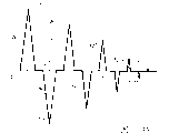
Fig. 4 A is a curve map, a routine output signal 30 of sensitization (demagnetization) mark 10 that is produced by driver element 16 (Fig. 2) is shown, thereby turn-on flag 10 is used for the detection by EAS system 3.More particularly, Fig. 4 draws the electric current with respect to the output signal 30 of time.For example with reference to figure 1-3.
For mark 10 is demagnetized, processor 12 is opened selectively and is disconnected first group and second group of contact maker 20,22 (Fig. 3), has the output signal 30 of a plurality of pulse 32A to 32I with generation, is referred to as pulse 32.And, by opening and turn-off current switchgear 20,22 with the number of times that calculated selectively, the waveform that processor 12 can be as requested, generation output signal 30.For example, signal 30 current impulse 32 is shown amplitude in time and the decay waveform of decay.More particularly, processor 12 is by shortening the corresponding duty cycle of each pulse, promptly opens in the shorter time and disconnects corresponding contact maker 20,22, and the amplitude of pulse 32 is reduced in time.Like this, for example, from T
3To T
5Time period than from T
0To T
2Time period shorter.In one embodiment, the duty cycle of processor 10 each succeeding impulse 32 of calculating is 92% of previous pulse.
Produce output signal 30, processor 12 is at T
0Constantly open first group of contact maker 20, in output signal, form first current impulse 32, and make electric current flow through coil 8 (Fig. 3).At T
1Constantly, processor 12 disconnects first group of contact maker 20, and electric current is descended from peak value 33, flows through coil 8 up to no longer including electric current constantly at T2.
After producing current impulse 33, processor 12 is at T
3Constantly open second group of contact maker 22, form second current impulse 35, and make electric current flow through coil 8 along direction with the opposite current of pulse 33.At T
4The place, processor 12 disconnects second group of contact maker 20, and electric current is descended from peak value 35, up at T
5Constantly no longer include electric current and flow through coil 8.
Electric current rising and decline subsequently that it should be noted that pulse 32 have constant substantially speed.In other words, electric current in the mode of generally linear respectively from T
0To T
1With from T
1To T
2Increase and decline.With by sine-shaped traditional RCL circuit different be, the signal that driver element 16 current changing rates of output (di/dt) are constant substantially, according to following formula:
Wherein, compare with Ldi/dt, iR is less.As a result, rise and descend with constant rate of change in an identical manner in magnetic field 7.This has many advantages, comprises having improved marker detection.
For the mark 10 that detects sensitization, control module 6 detects the signal that is sent by mark 10 when mark 10 is exposed to magnetic field 7.The signal intensity that is produced by mark 10 is the function of the rate of change of the position of mark 10 in magnetic field 7 and the electric current that flows through coil 8.Because the variation of output signals rate that is produced by driver element 16 is constant substantially, so the intensity of signal can and not reduce and changes with the increase in magnetic field 7.Do not change because control module does not need to compensate the signal that the slope variation owing to magnetic field 7 causes, thereby simplified detection the existence of mark 10.
In addition, control module 6 can determine that whether mark 10 is by sensitization or by desensitization according to the signal harmonic content that is produced by mark 10.Yet the rate of change of surrounding magnetic field can influence the harmonic content of the signal that is sent by mark greatly.Because the variation of output signals rate that is produced by driver element 16 is constant substantially, thereby harmonic content can and not reduce to change owing to the increase in magnetic field 7.As a result, compare with the legacy system by the rate of change of sinusoidal curve or other nonlinear waveform, control module 6 can be easier to certification mark and distinguish sensitization and mark desensitization.
Fig. 4 B is a curve map, and the output signal 36 that another example is produced by driver element 16 (Fig. 2) is shown.Processor 12 is opened selectively and is disconnected first group and second group of contact maker 20,22 (Fig. 3), has the output signal 36 of a plurality of pulse 38A to 38E (being referred to as pulse 38) with generation.Particularly, processor 12 produces and has abundant equal amplitude 37,40 and equate duration T substantially
DPulse 38.It should be noted that processor 12 can Control current switchgear 20,22, to change the time interval Δ T between the succeeding impulse
1, Δ T
2, Δ T
3, Δ T
4Thereby, influence the total time of output signal 36, and therefore change the effective frequency of output signal 36.
This embodiment can be particularly conducive to the neighbourhood noise of avoiding under the characteristic frequency.For example, EAS system 3 can comprise the circuit that is similar to driver element 16, has high-frequency interrogation zone with generation, is used to inquire after EAS mark 10.Particularly, compare with being mainly used in the magnetic field 7 that mark 10 is carried out sensitization and desensitization, this high frequency interrogation field can produce the bigger signal intensity that receives from EAS mark 10.In addition, control module 6 can also be by changing the effective frequency that DC (direct current) supply voltage VDC changes interrogation field.
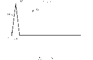
Fig. 5 is a curve map, and a routine output signal 49 that is produced by driver element 16 (Fig. 2) is shown, and is used for that mark 10 is carried out desensitization (magnetization) and handles, thereby disconnect mark 10.Want magnetization mark 10, processor 12 is opened selectively and is disconnected first group of contact maker group 20 (Fig. 3), has the output signal 49 of individual pulse 48 with generation.Produce output signal 49, processor 12 is at T
0Constantly open first group of contact maker 20, in output signal 49, form first current impulse 48, and make electric current flow through coil 8.At T
1Constantly, processor 12 disconnects first group of contact maker 20, makes electric current from peak value 47 landing, up to T
2The position no longer includes electric current and flows through coil 8.
Fig. 6 is a process flow diagram, is illustrated in the example operation pattern of EAS system 3 when producing magnetic field 7.Please refer to the output signal 30 of Fig. 4 for example.
At first, processor 12 calculates the peak amplitude 33 (52) of the first current impulse 32A according to the target strength in magnetic field 7.When definite target peak amplitude, processor 12 can be considered Several Factors, the one or more configuration parameters that comprise the driving voltage VDC that records, set by user 4, the type of merchandise that mark 10 is pasted and the magnetic field intensity of detected previous generation as mentioned above.For example, the Typical Disposition parameter that the user can set comprises the media types of handling, as vocal cores, video tape, books, CD etc., the EAS default is become the registration and the pattern of checking out, set the state of EAS system verification mark 10, and set EAS system 3 for non-tupe, to read radio frequency (RF) information from mark 10.For example, when definite target peak amplitude, processor 2 can read (RFID) label of the radio frequency identifiers (radiofrequency identification) that is fixed on commodity or the media, so that be identified for the correct parameter of sensitization or desensitization specific label.
According to the peak value that is calculated, processor 12 is determined the opening time TIME of the contact maker of driver element 16
ONWith TIME trip time
OFF, so that produce current impulse (54) with the peak value that is calculated.Then, processor 12 determines that according to desired signal waveform (56) electric current should flow through the direction of coil 8.For example, the output signal of Fig. 4 has a kind of waveform, and several current impulses 32 wherein are its polarity alternately, produces the electric current that direction replaces.
According to these directions, processor 12 is opened first group and second group of contact maker 20,22 selectively.More particularly, drive current to pass through coil 8 along first direction, processor 12 makes it to open first group of contact maker 20 (58) for height by drive controlling line C1, up to having passed through opening time TIME
ON(62).For example, in current impulse 32A, opening time TIME
ONEqual T
1At TIME
ONDuring expiration, processor 12 makes it to disconnect first group of contact maker 20 (66) for hanging down by drive controlling line C1, up to having passed through TIME trip time
OFF(70).For example, in current impulse 32A, trip time TIME
OFFEqual T
3-T
1
After the pulse that produces first polarity, processor 12 judges whether the target peak amplitude has drop to floor level (74), and if then finish this process.For example, current impulse 33I has the amplitude of the floor level that is lower than a certain regulation, makes processor 12 stop to produce pulse train 32.
But, if target amplitude does not also reach floor level, then processor 12 is by calculating new target amplitude (52) and corresponding opening time TIME
ONWith TIME trip time
OFF, repeat this process.In this repeated, processor 12 can be selected to make it to be height by drive controlling line C2, along coil 8 drive currents (56), opens second group of contact maker 22 (60), up to having passed through opening time TIME
ON(64).For example, in current impulse 32B, opening time TIME
ONEqual T
4-T
3At TIME
ONDuring expiration, processor 12 makes it to be low (68) by drive controlling line C1, disconnects second group of contact maker 22, up to having passed through TIME trip time
OFF(72).By this way, processor 12 can repeat this process, thereby according to desired waveform, generation has the output signal of one or more current impulses.
Said process is used for for example, and can easily be revised by EAS system 3.For example, processor 12 can repeatedly be inquired after mark, and produces more high-intensity magnetic field, meets an acceptable level up to the surplus value that records of this mark of signal indication that receives from mark.When mark being carried out sensitization and handle, processor 12 can control Driver Circuit 16, makes this mark through a succession of more and more high-intensity magnetic field, up to the surplus value landing of this mark and reach the floor level of regulation.Similarly, when mark being carried out desensitization when handling, processor 12 can control Driver Circuit 16, makes the magnetic field of this mark through a succession of more and more higher magnetic intensity, reaches the maximum horizontal of a regulation up to the surplus value of this mark.
Adopt this mode, have the EAS system 3 of the ability of the ability of inquiring after mark and controlling magnetic field, can guarantee that mark is subjected to the effect into the necessary field minimum of result that obtains to require.When reaching target level or when the greatest limit that reaches field intensity, processor 12 can stop this process.
Accurately the ability of controlling magnetic field has many advantages, is included in all marks are had under the situation of residual value of approximate par, has strengthened detectability.And these characteristics can be particularly conducive to the market that is used for magnetic field is had harsh regulation.
Fig. 7 is a schematic diagram, and another routine embodiment of driver element 76 is shown, and it comprises the electric capacity 78 in parallel with coil 8.Among this embodiment, driver element 76 can provide the output signal with one or more current impulses, so that electric capacity 78 is carried out, makes magnetic field 7 with very high frequency resonance.Adopt this mode, driver element 76 can be used for producing magnetic field when the state of checking EAS mark, and detects EAS thus and mark whether to exist.
Above, various embodiment of the present invention has been described.Various embodiment are within the scope of claims.
Claims (27)
1. one kind is used for the equipment that the magnetic electron merchandise surveillance system produces magnetic field, it is characterized in that it comprises:
Coil is in order to produce and the interactional magnetic field of electronic article surveillance mark;
Driver element, it comprises contact maker, and in order to export a signal, described signal has one or more pulses of the described coil of excitation; And
Programmable processor, in order to calculate the target strength in described magnetic field, and according to the described target strength that calculates, control the contact maker of described driver element, to produce described pulse, wherein calculate described target strength according to one in the following factor to small part: the intensity of posting the type of the commodity of described electronic marker, detected driving voltage and the magnetic field detection of previous generation being obtained.
2. equipment as claimed in claim 1 is characterized in that it also comprises the user interface that receives described configuration parameter from the user, and wherein said programmable processor calculates described target strength according to described configuration parameter.
3. equipment as claimed in claim 1, it is characterized in that it also comprises the detecting device with described processor coupling, in order to detect the actual strength in described magnetic field, wherein said processor dynamically is updated to the unlatching duration that described pulse calculates according to described detected actual strength.
4. equipment as claimed in claim 3 is characterized in that, according to described detected actual strength, described processor is dynamically determined the pulse number of described signal.
5. equipment as claimed in claim 1, it is characterized in that, described contact maker comprises first group and second group of contact maker, and wherein said processor is opened selectively and disconnected described first group and second group of contact maker, to produce described signal.
6. equipment as claimed in claim 6, it is characterized in that, described processor is opened described first group of contact maker selectively, pass through coil so that drive described signal along first direction, and open described second group of contact maker selectively, pass through coil along second direction so that drive described signal.
7. equipment as claimed in claim 1 is characterized in that described processor is controlled described driver element, so that change the duration between the succeeding impulse.
8. equipment as claimed in claim 1 is characterized in that described processor is controlled described driver element, so that produce the deamplification that described signal reduces as pulse duty cycle.
9. equipment as claimed in claim 8 is characterized in that, described processor makes each follow-up duty cycle reduce a constant percentage of described previous duty cycle.
10. equipment as claimed in claim 8, it is characterized in that, the function that described processor also will be calculated to be described target strength with the duty cycle and the amplitude of each pulse correlation, and according to described duty cycle that calculates and amplitude, control the contact maker of described driver element, to produce described pulse.
11. equipment as claimed in claim 8 is characterized in that, described processor is controlled described contact maker, makes that each follow-up duty cycle approximately is 92% of a last duty cycle.
12. equipment as claimed in claim 1 is characterized in that, described processor is controlled described contact maker, makes the electric current by described coil increase and reduce with constant substantially speed.
13. equipment as claimed in claim 1 is characterized in that, described processor makes described driver element be in first state of the described coil of excitation in order and makes currentless second state of described coil, thereby controls described driver element, to generate described signal.
14. equipment as claimed in claim 1 is characterized in that, described processor is opened described switch selectively according to the waveform able to programme of the orientation that limits each pulse.
15. one kind is used for the method that the magnetic electron merchandise surveillance system produces magnetic field, it is characterized in that it comprises:
Calculate target strength with the interactional magnetic field of electronic article surveillance mark with programmable processor, wherein calculate described target strength: configuration parameter, the type of posting the commodity of described electronic article surveillance mark, detected driving voltage and the intensity that the magnetic field detection of previous generation is obtained according in the following factor at least one;
Described programmable processor is opened and the turn-off current switchgear selectively according to the described target strength that calculates, and has the signal of one or more current impulses with generation; And
Drive described signal by a coil, to generate described magnetic field.
16. method as claimed in claim 15 is characterized in that, it also comprises:
According to the described target strength that calculates, calculate the number of the current impulse that will generate and each duty cycle of described current impulse; And
Open selectively and disconnect described contact maker, to produce the described current impulse number that calculates, each current impulse is to produce according to the described corresponding duty cycle that calculates.
17. method as claimed in claim 16 is characterized in that, it also comprises the duty cycle that reduces described current impulse, to produce a deamplification.
18. method as claimed in claim 15 is characterized in that, also comprises:
Determine the waveform of the current impulse of described signal; And
According to described waveform, open selectively and disconnect described contact maker.
19. method as claimed in claim 19, it is characterized in that, be used for determining that the described step of waveform comprises the orientation of determining each pulse able to programmely, and the described step of opening selectively and disconnecting described contact maker comprises opens in order and disconnects described switchgear, thereby produces described pulse according to determined orientation.
20. method as claimed in claim 15 is characterized in that, the described step that is used to produce described signal comprises with constant substantially speed, increases and reduce the electric current of described signal.
21. method as claimed in claim 15 is characterized in that, it also comprises:
Detect the intensity in described magnetic field; And
According to described detected intensity, produce described signal.
22. method as claimed in claim 15 is characterized in that, it also comprises:
By user interface, receive described configuration parameter from the user; And
According to described configuration parameter, calculate described target strength.
23. method as claimed in claim 15 is characterized in that, described contact maker comprises first group of contact maker, and described pulse comprises first group pulse, and described method also comprises:
Open and disconnect described first group of contact maker,, thereby the magnetic field of generation is become along first magnetic field of first direction orientation so that drive described first group of current impulse by described coil; And
Open and disconnect described second group of contact maker,, thereby produce along second magnetic field of second direction orientation so that drive described second group of current impulse by described coil.
24. method as claimed in claim 23 is characterized in that, described first direction and described second direction opposite orientation.
25. method as claimed in claim 23 is characterized in that, it also comprises:
Calculate the target peak amplitude of each pulse in described first group pulse;
According to described target peak amplitude, calculate each first opening time; And
Make described first group of contact maker open described first opening time, to produce described first group pulse.
26. method as claimed in claim 23 is characterized in that, it also comprises:
The target peak amplitude of each pulse in described second group pulse is calculated the function of the target peak amplitude that becomes described first pulse;
According to the target peak amplitude of each pulse in described second group pulse, calculate corresponding second opening time; And
Make described second group of contact maker open described second opening time, to produce described second group pulse.
27. method as claimed in claim 15 is characterized in that, described contact maker comprises first group of contact maker, and described method also comprises:
Open and disconnect described first group of contact maker;
Open and disconnect second group of contact maker;
Repeat the unlatching and the disconnection of described first group and second group contact maker in order, to produce a series of pulses, wherein said current impulse has the amplitude of following a decay waveform; And
When described amplitude has decayed to minimum level, cut off described a series of current impulse.
Applications Claiming Priority (2)
| Application Number | Priority Date | Filing Date | Title |
|---|---|---|---|
| US09/880,486 | 2001-06-13 | ||
| US09/880,486 US6696951B2 (en) | 2001-06-13 | 2001-06-13 | Field creation in a magnetic electronic article surveillance system |
Publications (2)
| Publication Number | Publication Date |
|---|---|
| CN1516857A CN1516857A (en) | 2004-07-28 |
| CN100338636C true CN100338636C (en) | 2007-09-19 |
Family
ID=25376385
Family Applications (1)
| Application Number | Title | Priority Date | Filing Date |
|---|---|---|---|
| CNB02811972XA Expired - Fee Related CN100338636C (en) | 2001-06-13 | 2002-05-13 | Field creation in magnetic electronic article surveillance system |
Country Status (12)
| Country | Link |
|---|---|
| US (2) | US6696951B2 (en) |
| EP (1) | EP1399899B1 (en) |
| JP (1) | JP4122285B2 (en) |
| CN (1) | CN100338636C (en) |
| AR (1) | AR034472A1 (en) |
| AT (1) | ATE286288T1 (en) |
| AU (1) | AU2002311931B2 (en) |
| BR (1) | BR0210305A (en) |
| CA (1) | CA2448443A1 (en) |
| DE (1) | DE60202471T2 (en) |
| HK (1) | HK1070455A1 (en) |
| WO (1) | WO2002101677A1 (en) |
Families Citing this family (22)
| Publication number | Priority date | Publication date | Assignee | Title |
|---|---|---|---|---|
| US6724191B1 (en) | 2000-05-09 | 2004-04-20 | Admiralty Corporation | Systems and methods useful for detecting presence and/or location of various materials |
| US6696951B2 (en) * | 2001-06-13 | 2004-02-24 | 3M Innovative Properties Company | Field creation in a magnetic electronic article surveillance system |
| US7255909B2 (en) * | 2002-02-19 | 2007-08-14 | 3M Innovative Properties Company | Security laminate |
| US20030184636A1 (en) * | 2002-02-19 | 2003-10-02 | Graham Paul D. | Image receptive material comprising cationically charged inorganic particles |
| US7275040B2 (en) * | 2002-09-12 | 2007-09-25 | Mineral Lassen Llc | RFID security device for optical disc |
| US6946962B2 (en) * | 2003-10-29 | 2005-09-20 | Sensormatic Electronics Corporation | Electronic article surveillance marker deactivator using inductive discharge |
| US7444120B2 (en) * | 2004-05-11 | 2008-10-28 | Sensormatic Electronics Corporation | Active transmitter ringdown for switching power amplifier |
| US7301459B2 (en) * | 2004-05-11 | 2007-11-27 | Sensormatic Electronics Corporation | Closed loop transmitter control for power amplifier in an EAS system |
| US7068172B2 (en) * | 2004-05-21 | 2006-06-27 | Xiao Hui Yang | Method and apparatus for deactivating an EAS device |
| US7658980B2 (en) * | 2004-08-06 | 2010-02-09 | 3M Innovative Properties Company | Tamper-indicating printable sheet for securing documents of value and methods of making the same |
| US7648744B2 (en) * | 2004-08-06 | 2010-01-19 | 3M Innovative Properties Company | Tamper-indicating printable sheet for securing documents of value and methods of making the same |
| JP4483497B2 (en) * | 2004-09-16 | 2010-06-16 | 富士ゼロックス株式会社 | Magnetic detection device |
| WO2006057887A1 (en) * | 2004-11-22 | 2006-06-01 | Sensormatic Electronics Corporation | H-bridge activator/deactivator and method for activating/deactivating eas tags |
| MX2007012435A (en) * | 2005-03-07 | 2007-12-05 | Sensormatic Electronics Corp | Adaptively transmitting a signal for activating a tag. |
| AU2012202729B2 (en) * | 2005-03-07 | 2015-04-09 | Sensormatic Electronics Llc | Adaptively transmitting a signal for activating a tag |
| JP4602811B2 (en) * | 2005-03-24 | 2010-12-22 | グンゼ株式会社 | Tag detection device |
| US7391324B1 (en) | 2005-11-14 | 2008-06-24 | Gpk Products, Inc. | Locator plug system |
| US7825806B2 (en) * | 2007-09-25 | 2010-11-02 | Symbol Technologies, Inc. | Optimizing RFID reader duty cycle or power to preserve battery life |
| US20090212952A1 (en) * | 2008-02-22 | 2009-08-27 | Xiao Hui Yang | Method and apparatus for de-activating eas markers |
| GB2476050B (en) * | 2009-12-08 | 2013-11-13 | Redcliffe Magtronics Ltd | Tag detector |
| US9824245B2 (en) * | 2013-03-14 | 2017-11-21 | Tyco Fire & Security Gmbh | Methods, systems and devices for electronic article surveillance deactivation having randomized transmission rates |
| CN107833425B (en) * | 2017-10-24 | 2020-08-04 | 深圳中安安防科技有限公司 | Remote burglar alarm control system and method |
Citations (3)
| Publication number | Priority date | Publication date | Assignee | Title |
|---|---|---|---|---|
| US5907465A (en) * | 1998-08-13 | 1999-05-25 | Sensormatic Electronics Corporation | Circuit for energizing EAS marker deactivation device with DC pulses of alternating polarity |
| WO2000027137A1 (en) * | 1998-11-04 | 2000-05-11 | Checkpoint Systems, Inc. | Rfid tag having parallel resonant circuit for magnetically decoupling tag from its environment |
| WO2001013345A1 (en) * | 1999-08-16 | 2001-02-22 | Checkpoint Systems, Inc. | Electronic article security system employing variable time shifts |
Family Cites Families (18)
| Publication number | Priority date | Publication date | Assignee | Title |
|---|---|---|---|---|
| US5049857A (en) * | 1989-07-24 | 1991-09-17 | Sensormatic Electronics Corporation | Multi-mode electronic article surveillance system |
| US6742709B2 (en) * | 1990-09-11 | 2004-06-01 | Metrologic Instruments, Inc. | Bar code symbol reading system employing electronically-controlled raster-type laser scanner for reading bar code symbols during hands-on and hands-free modes of operation |
| US5805065A (en) * | 1991-05-08 | 1998-09-08 | Minnesota Mining And Manufacturing Company | Electro-magnetic desensitizer |
| US5341125A (en) * | 1992-01-15 | 1994-08-23 | Sensormatic Electronics Corporation | Deactivating device for deactivating EAS dual status magnetic tags |
| US5493275A (en) * | 1994-08-09 | 1996-02-20 | Sensormatic Electronics Corporation | Apparatus for deactivation of electronic article surveillance tags |
| US5844485A (en) * | 1995-02-03 | 1998-12-01 | Sensormatic Electronics Corporation | Article of merchandise with EAS and associated indicia |
| US5680106A (en) * | 1995-10-27 | 1997-10-21 | International Business Machines Corporation | Multibit tag with stepwise variable frequencies |
| US5625339A (en) | 1996-01-08 | 1997-04-29 | Minnesota Mining And Manufacturing Company | Apparatus for changing the status of magnetic markers in an electronic article surveillance system |
| US6362737B1 (en) * | 1998-06-02 | 2002-03-26 | Rf Code, Inc. | Object Identification system with adaptive transceivers and methods of operation |
| US5781111A (en) | 1996-09-26 | 1998-07-14 | Sensormatic Electronics Corporation | Apparatus for deactivation of electronic article surveillance tags |
| US6002335A (en) | 1998-02-18 | 1999-12-14 | 3M Innovative Properties Company | Small magnet resensitizer apparatus for use with article surveillance systems |
| US5926095A (en) * | 1998-03-18 | 1999-07-20 | Sensormatic Electronics Corporation | Transverse field annealing process to form E.A.S. marker having a step change in magnetic flux |
| US6057763A (en) | 1998-04-10 | 2000-05-02 | 3M Innovative Properties Company | Method and apparatus for activating and deactivating electromagnetic article surveillance markers |
| US6181249B1 (en) | 1999-01-07 | 2001-01-30 | Sensormatic Electronics Corporation | Coil driving circuit for EAS marker deactivation device |
| US6169483B1 (en) * | 1999-05-04 | 2001-01-02 | Sensormatic Electronics Corporation | Self-checkout/self-check-in RFID and electronics article surveillance system |
| US6486782B1 (en) * | 2000-07-07 | 2002-11-26 | 3M Innovative Properties | Device for changing the status of dual status magnetic electronic article surveillance markers |
| US6696951B2 (en) * | 2001-06-13 | 2004-02-24 | 3M Innovative Properties Company | Field creation in a magnetic electronic article surveillance system |
| US6778087B2 (en) * | 2001-06-15 | 2004-08-17 | 3M Innovative Properties Company | Dual axis magnetic field EAS device |
-
2001
- 2001-06-13 US US09/880,486 patent/US6696951B2/en not_active Expired - Fee Related
-
2002
- 2002-05-13 AU AU2002311931A patent/AU2002311931B2/en not_active Ceased
- 2002-05-13 WO PCT/US2002/015528 patent/WO2002101677A1/en active IP Right Grant
- 2002-05-13 BR BR0210305-2A patent/BR0210305A/en not_active IP Right Cessation
- 2002-05-13 CA CA002448443A patent/CA2448443A1/en not_active Abandoned
- 2002-05-13 JP JP2003504354A patent/JP4122285B2/en not_active Expired - Fee Related
- 2002-05-13 EP EP02739273A patent/EP1399899B1/en not_active Expired - Lifetime
- 2002-05-13 DE DE60202471T patent/DE60202471T2/en not_active Expired - Lifetime
- 2002-05-13 AT AT02739273T patent/ATE286288T1/en not_active IP Right Cessation
- 2002-05-13 CN CNB02811972XA patent/CN100338636C/en not_active Expired - Fee Related
- 2002-06-12 AR ARP020102207A patent/AR034472A1/en active IP Right Grant
-
2004
- 2004-01-08 US US10/755,184 patent/US6902110B2/en not_active Expired - Fee Related
- 2004-08-26 HK HK04106428A patent/HK1070455A1/en not_active IP Right Cessation
Patent Citations (3)
| Publication number | Priority date | Publication date | Assignee | Title |
|---|---|---|---|---|
| US5907465A (en) * | 1998-08-13 | 1999-05-25 | Sensormatic Electronics Corporation | Circuit for energizing EAS marker deactivation device with DC pulses of alternating polarity |
| WO2000027137A1 (en) * | 1998-11-04 | 2000-05-11 | Checkpoint Systems, Inc. | Rfid tag having parallel resonant circuit for magnetically decoupling tag from its environment |
| WO2001013345A1 (en) * | 1999-08-16 | 2001-02-22 | Checkpoint Systems, Inc. | Electronic article security system employing variable time shifts |
Also Published As
| Publication number | Publication date |
|---|---|
| US20040145476A1 (en) | 2004-07-29 |
| EP1399899B1 (en) | 2004-12-29 |
| ATE286288T1 (en) | 2005-01-15 |
| JP4122285B2 (en) | 2008-07-23 |
| CN1516857A (en) | 2004-07-28 |
| DE60202471D1 (en) | 2005-02-03 |
| AU2002311931B2 (en) | 2007-07-26 |
| BR0210305A (en) | 2004-07-13 |
| US20020196144A1 (en) | 2002-12-26 |
| DE60202471T2 (en) | 2005-12-29 |
| EP1399899A1 (en) | 2004-03-24 |
| HK1070455A1 (en) | 2005-06-17 |
| US6696951B2 (en) | 2004-02-24 |
| JP2004530228A (en) | 2004-09-30 |
| CA2448443A1 (en) | 2002-12-19 |
| AR034472A1 (en) | 2004-02-25 |
| US6902110B2 (en) | 2005-06-07 |
| WO2002101677A1 (en) | 2002-12-19 |
Similar Documents
| Publication | Publication Date | Title |
|---|---|---|
| CN100338636C (en) | Field creation in magnetic electronic article surveillance system | |
| EP0455438B1 (en) | Magnetic recording system | |
| KR20210122233A (en) | Variable Output Impedance RF Generator | |
| CN105453199B (en) | Method and apparatus for demagnetization transformer core closed loop | |
| US9528625B2 (en) | Current driving system for a solenoid | |
| EP0696785B1 (en) | Apparatus for deactivation of electronic article surveillance tags | |
| CN104302028B (en) | High-frequency heating apparatus and its power control method and power control | |
| CN105021241B (en) | The electromagnetic flow meter excitation control system of PWM based on current error control | |
| CN107332358B (en) | A kind of devices and methods therefor reducing the transient electromagnetic turn-off time | |
| AU2002311931A1 (en) | Field creation in a magnetic electronic article surveillance system | |
| JP4709899B2 (en) | Deactivation technology for electronic article surveillance labels using energy recovery | |
| CN106593737B (en) | Common-rail injector solenoid valve armature is attracted point detection device | |
| US5017871A (en) | Gradient current speed-up circuit for high-speed NMR imaging system | |
| Zhu et al. | Bipolar steep pulse current source for highly inductive load | |
| CA2206173C (en) | Improvements in time-domain electromagnetic geophysical mapping instruments | |
| EP2237405B1 (en) | Control device for the change of the driving modality of an electromagnetic load | |
| CN105984426B (en) | Vehicle, Intelligent key system of vehicle and its card seeking method | |
| DE69929773D1 (en) | STIMULATION SYSTEM FOR THERAPY WITH PULSED ELECTROMAGNETIC FIELDS WITH TWO-PHASE COIL | |
| US6768977B1 (en) | Method and circuit for modeling a voice coil actuator of a mass data storage device | |
| Scott | Efficient drive signals for broadband CW electromagnetic induction sensors | |
| CN100359796C (en) | Control system of electric machine for dynamic changing wavecurve of electric machine energized current | |
| CN105979463B (en) | Automatic magnetization testing equipment for program-controlled telephone receiver | |
| AU2020100823A4 (en) | A Device For Eliminating Transient Electromagnetic Primary Field | |
| US8878515B1 (en) | Constant current metal detector | |
| Picatoste et al. | Sine wave filter for stepper motor drives working with long cables |
Legal Events
| Date | Code | Title | Description |
|---|---|---|---|
| C06 | Publication | ||
| PB01 | Publication | ||
| C10 | Entry into substantive examination | ||
| SE01 | Entry into force of request for substantive examination | ||
| C14 | Grant of patent or utility model | ||
| GR01 | Patent grant | ||
| C17 | Cessation of patent right | ||
| CF01 | Termination of patent right due to non-payment of annual fee |
Granted publication date: 20070919 Termination date: 20110513 |