BRPI1105500B1 - upper connector for a rope of a floating structure with ropes, floating structure with ropes and tensioning unit - Google Patents
upper connector for a rope of a floating structure with ropes, floating structure with ropes and tensioning unit Download PDFInfo
- Publication number
- BRPI1105500B1 BRPI1105500B1 BRPI1105500-6A BRPI1105500A BRPI1105500B1 BR PI1105500 B1 BRPI1105500 B1 BR PI1105500B1 BR PI1105500 A BRPI1105500 A BR PI1105500A BR PI1105500 B1 BRPI1105500 B1 BR PI1105500B1
- Authority
- BR
- Brazil
- Prior art keywords
- chain
- upper connector
- support
- frame
- fact
- Prior art date
Links
Images


Classifications
-
- B—PERFORMING OPERATIONS; TRANSPORTING
- B63—SHIPS OR OTHER WATERBORNE VESSELS; RELATED EQUIPMENT
- B63B—SHIPS OR OTHER WATERBORNE VESSELS; EQUIPMENT FOR SHIPPING
- B63B21/00—Tying-up; Shifting, towing, or pushing equipment; Anchoring
- B63B21/04—Fastening or guiding equipment for chains, ropes, hawsers, or the like
- B63B21/10—Fairleads
-
- B—PERFORMING OPERATIONS; TRANSPORTING
- B63—SHIPS OR OTHER WATERBORNE VESSELS; RELATED EQUIPMENT
- B63B—SHIPS OR OTHER WATERBORNE VESSELS; EQUIPMENT FOR SHIPPING
- B63B21/00—Tying-up; Shifting, towing, or pushing equipment; Anchoring
- B63B21/04—Fastening or guiding equipment for chains, ropes, hawsers, or the like
-
- B—PERFORMING OPERATIONS; TRANSPORTING
- B63—SHIPS OR OTHER WATERBORNE VESSELS; RELATED EQUIPMENT
- B63B—SHIPS OR OTHER WATERBORNE VESSELS; EQUIPMENT FOR SHIPPING
- B63B21/00—Tying-up; Shifting, towing, or pushing equipment; Anchoring
- B63B21/50—Anchoring arrangements or methods for special vessels, e.g. for floating drilling platforms or dredgers
-
- B—PERFORMING OPERATIONS; TRANSPORTING
- B63—SHIPS OR OTHER WATERBORNE VESSELS; RELATED EQUIPMENT
- B63B—SHIPS OR OTHER WATERBORNE VESSELS; EQUIPMENT FOR SHIPPING
- B63B22/00—Buoys
- B63B22/04—Fixations or other anchoring arrangements
-
- B—PERFORMING OPERATIONS; TRANSPORTING
- B63—SHIPS OR OTHER WATERBORNE VESSELS; RELATED EQUIPMENT
- B63B—SHIPS OR OTHER WATERBORNE VESSELS; EQUIPMENT FOR SHIPPING
- B63B21/00—Tying-up; Shifting, towing, or pushing equipment; Anchoring
- B63B21/18—Stoppers for anchor chains
-
- B—PERFORMING OPERATIONS; TRANSPORTING
- B63—SHIPS OR OTHER WATERBORNE VESSELS; RELATED EQUIPMENT
- B63B—SHIPS OR OTHER WATERBORNE VESSELS; EQUIPMENT FOR SHIPPING
- B63B22/00—Buoys
- B63B22/18—Buoys having means to control attitude or position, e.g. reaction surfaces or tether
Abstract
CONECTOR SUPERIOR PARA UMA CORDA DE UMA ESTRUTURA FLUTUANTE COM CORDAS E ESTRUTURA FLUTUANTE COM CORDAS. A presente invenção refere-se a um conector superior para uma 5 corda de uma boia submarina que compreende um suporte, um membro de alavanca móvel em torno de um eixo geométrico pivô, e o mecanismo de trava da corrente montado sobre o membro de alavanca a ser situado abaixo do eixo geométrico pivô em uso. O membro de alavanca é conectado de maneira giratória no suporte através de uma junção flexível disposta para 10 suportar uma carga extensível exercida por uma corrente superior da corda quando encaixada no mecanismo de trava da corrente. A junção flexível melhorando a resistência à fadiga por envergadura da corrente superior. Uma armação se estendendo para cima a partir do suporte para conduzir uma roldana para a corrente superior. Um membro de alavanca 15 conectado de maneira giratória se estendendo para baixo a partir do suporte. O membro de alavanca sendo giratório em relação ao suporte e à armação, permitindo uma disposição compacta que impede a armação, a corrente su-perior ou a roldana de colidir com o revestimento da boia.SUPERIOR CONNECTOR FOR A STRING OF A FLOATING STRUCTURE WITH STRINGS AND FLOATING STRUCTURE WITH STRINGS. The present invention relates to an upper connector for an underwater buoy rope comprising a support, a movable lever member around a pivot geometric axis, and the chain locking mechanism mounted on the lever member a be located below the pivot geometric axis in use. The lever member is pivotally connected to the support through a flexible joint arranged to support an extensible load exerted by an upper chain of the rope when attached to the chain locking mechanism. The flexible joint improves the fatigue resistance of the upper chain. A frame extending upwards from the support to guide a pulley to the upper chain. A lever member 15 pivotally connected extending downwardly from the support. The lever member being rotatable in relation to the support and the frame, allowing a compact arrangement that prevents the frame, the upper chain or the pulley from colliding with the cover of the float.
Description
[001] A presente invenção refere-se a sistemas de tensionamento e conexão para cordas de estruturas flutuantes, tais como boias submarinas usadas em sistemas de suspensão ("riser") híbridos ou desacoplados.[001] The present invention relates to tensioning and connection systems for floating structure ropes, such as underwater buoys used in hybrid or decoupled suspension systems ("risers").
[002] Os sistemas híbridos de suspensão são conhecidos por vários anos por transportarem fluidos de poço do leito marinho para a instalação em superfície. Por exemplo, em um sistema híbrido de suspensão descrito em nosso Pedido No PCT/GB2011/051223, um suporte para a suspensão do leito marinho se estende a partir dos alicerces do leito marinho até uma boia de suporte para suspensão, presa de maneira flutuável em meia água.[002] Hybrid suspension systems have been known for several years for transporting well fluids from the seabed to surface installation. For example, in a hybrid suspension system described in our Order. In PCT / GB2011 / 051223, a support for the seabed suspension extends from the seabed foundations to a suspension support buoy, attached in a floating way in half water.
[003] Uma boia de suporte para suspensão é às vezes referida na técnica pelo acrônimo BSR, derivado do termo em português 'boia de suporte de riser'. Por questões de rapidez, esse acrônimo será usado para identificar as boias de suporte para suspensão na descrição que se segue.[003] A support buoy for suspension is sometimes referred to in the technique by the acronym BSR, derived from the Portuguese term 'riser support buoy'. For the sake of speed, this acronym will be used to identify the suspension support buoys in the description that follows.
[004] Uma BSR é amarrada mediante tensão nos seus alicerces, para assentarem a uma profundidade abaixo da influência de uma provável ação de ondas. UMA BSR que mostrada no PCT/GB2011/051223 é em geral retangular na vista plana e possui quarto conjuntos (neste exemplo, pares) de cordas, cada conjunto sendo preso por conectores superiores a uma respectiva região de canto de uma BSR.[004] A BSR is tied under tension to its foundations, to settle to a depth below the influence of a probable wave action. A BSR that shown in PCT / GB2011 / 051223 is generally rectangular in the flat view and has four sets (in this example, pairs) of strings, each set being attached by connectors above a respective corner region of a BSR.
[005] Os tubos de suspensão se estendem entre o leito marinho e uma BSR com cordas. Os tubos de suspensão ficam tipicamente pendurados livremente a partir de uma BSR suspensões catenárias de aço ou SCRs, embora outros materiais possam ser usados para esses tubos. Tubos flexíveis conectores ("flexible tubos conectores") se comunicando com as SCRs que se penduram como catenárias que se estendem a partir de uma BSR até a embarcação FPSO (produção, armazenamento e descarga flutuante) ou outra instalação em superfície, tai como uma plataforma. Os tubos conectores complacentes de-sacoplam as SCRs mais rígidas do movimento de superfície induzido pelas ondas marés. Consequentemente, as SCRs passam por menos tensão e fatiga.[005] The suspension tubes extend between the seabed and a BSR with ropes. Suspension tubes are typically hung freely from a BSR steel catenary suspensions or SCRs, although other materials can be used for these tubes. Connecting flexible tubes ("flexible connecting tubes") communicating with SCRs that hang like catenaries that extend from a BSR to the FPSO vessel (production, storage and floating discharge) or other surface installation, as well as a platform . The compliant connector tubes de-sac the most rigid SCRs of the surface movement induced by tidal waves. As a result, SCRs experience less stress and fatigue.
[006] Para atender às exigências operacionais é importante que uma BSR seja mantida a uma profundidade apropriada e em um local e sentido apropriado na água. Também é importante que as cordas suportem uma parcela apropriada da carga flutuante de uma BSR. Um problema quanto a isso é que elementos com cordas tais como fio com filamento em espiral (SSW) passarão por várias fases de extensão quando submetidos à alta tensão.[006] To meet operational requirements it is important that a BSR is maintained at an appropriate depth and in an appropriate location and direction in the water. It is also important that the strings support an appropriate portion of the floating load of a BSR. A problem in this regard is that elements with strings such as spiral filament yarn (SSW) will go through several extension phases when subjected to high tension.
[007] Enquanto algumas características de extensão são bem conhecidas e facilmente previsíveis, outras características de extensão não são precisamente previsíveis. Sobre grandes extensões de corda tais como 2000m ou mais, essa imprevisibilidade produz imprecisões que devem ser levadas em consideração. Esse problema é composto pela expansão e contração térmica, extensão devido à rotação e extensão devido ao desgaste.[007] While some extension characteristics are well known and easily predictable, other extension characteristics are not precisely predictable. Over large lengths of rope such as 2000m or more, this unpredictability produces inaccuracies that must be taken into account. This problem is compounded by thermal expansion and contraction, extension due to rotation and extension due to wear.
[008] Por essas razões, é necessário ter um sistema para o ajuste tensão e equilíbrio das cargas nas cordas. No PCT/GB2011/051223, o sistema de ajuste de tensão compreende módulos tensionadores montados sobre uma BSR que servem como um conector superior para uma respectiva corda. Cada módulo tensionador é montado sobre um respectiva alpendre para desembarque ("hang-off alpendre") definindo um suporte que se estende para fora como uma prateleira a partir de uma estrutura lateral de uma BSR.O módulo tensionador compreende travas de corrente funcionando como um mecanismo com catraca que se une aos elos de uma corrente superior conectada em um comprimento central do SSW da corda.[008] For these reasons, it is necessary to have a system for adjusting tension and balance of loads on the strings. In PCT / GB2011 / 051223, the tension adjustment system comprises tensioner modules mounted on a BSR that serve as an upper connector for a respective rope. Each tensioner module is mounted on a respective porch for landing ("hang-off porch") defining a support that extends outwards like a shelf from a side structure of a BSR.The tensioner module comprises chain locks acting as a ratchet mechanism that joins the links of an upper chain connected at a central length of the rope's SSW.
[009] As travas de corrente no PCT/GB2011/051223 são sustentadas na extremidade inferior de um membro guia que se estende para baixo como parte de um membro giratório e articulado sustentado em uma conexão no alpendre para desembarque. O membro articulado e a conexão possuem superfícies de sustentação parcialmente esféricas complementares que juntas definem uma junção com uma esfera e uma conexão.[009] The chain locks on PCT / GB2011 / 051223 are supported on the lower end of a guide member that extends downwards as part of a swiveling and articulated member sustained in a connection on the porch for disembarkation. The articulated member and the connection have complementary partially spherical support surfaces that together define a joint with a sphere and a connection.
[0010] O suporte esférico permite que o módulo tensionador se adapte a inclinações variadas do eixo geométrico de partida da corda associada. Isso é necessário porque a carga lateral aplicada pelas corrente de água significa que uma BSR não estará sempre flutuando diretamente acima de seus alicerces; e que também uma BSR pode se inclinar durante a instalação ou de outro modo durante a sua durabilidade operacional, por exemplo, quando as SCRs são fixadas ou removidas da boia. UMA BSR também pode passar pela influência sutil de forças de inclinação induzidas pelas ondas através do movimento dos tubos conectores que se estendem a partir de uma BSR na superfície. Consequentemente, com o tempo, os eixos geométricos de partida das cordas irão variar na inclinação relativa ao sentido vertical e à estrutura lateral de uma BSR. Caso sejam manuseados corretamente, eles podem causar concentrações de tensão nas correntes superiores das cordas adjacentes às suas conexões com uma BSR, o que pode levar a uma falha prematura das correntes superiores.[0010] The spherical support allows the tensioner module to adapt to varying inclinations of the starting axis of the associated rope. This is necessary because the lateral load applied by the water currents means that a BSR will not always be floating directly above its foundations; and that a BSR can also tilt during installation or otherwise during its operational durability, for example, when SCRs are attached or removed from the float. A BSR can also experience the subtle influence of wave-induced tilt forces through the movement of the connecting tubes that extend from a BSR on the surface. Consequently, over time, the geometric axes of departure of the strings will vary in the inclination relative to the vertical direction and the lateral structure of a BSR. If handled correctly, they can cause stress concentrations in the upper strings of the strings adjacent to their connections with a BSR, which can lead to premature failure of the upper currents.
[0011] Como as travas de corrente no PCT/GB2011/051223 são situadas abaixo do eixo geométrico pivô do suporte esférico, o membro guia que os sustenta define uma alavanca. O objetivo da alavanca é garantir que qualquer mudança na inclinação da corda em relação à BSR fará com que o membro articulado gire na conexão na mesma extensão. Tai movimento do membro articulado em relação à conexão é necessário para o alinhamento com o eixo geométrico de partida da corda.[0011] As the chain locks on PCT / GB2011 / 051223 are located below the pivot geometric axis of the spherical support, the guide member that supports them defines a lever. The purpose of the lever is to ensure that any change in the slope of the rope in relation to the BSR will cause the articulated member to rotate in the connection to the same extent. This movement of the articulated limb in relation to the connection is necessary for alignment with the geometric axis of the rope starting.
[0012] No PCT/GB2011/051223, um braço do membro articulado se estende para cima a partir do suporte esférico e termina em uma roldana sobre a qual uma parte traseira da corrente superior é coberta. A parte traseira da corrente superior termina com um peso morto fixado na sua extremidade livre, pendurada abaixo da roldana. Essa disposição exige cálculos para evitar o choque com a estrutura lateral vertical de uma BSR caso a corda adote um ângulo extremo de partida. De maneira específica, o eixo geométrico pivô do suporte esférico deve ser posicionado lateralmente longe o bastante da estrutura lateral, de modo que a parte de cima do braço, a roldana e a parte traseira da corrente superior não colidam com a estrutura lateral quando o braço girar no lado de dentro em torno do suporte.[0012] In PCT / GB2011 / 051223, an arm of the articulated member extends upwards from the spherical support and ends in a pulley on which a rear of the upper chain is covered. The rear of the upper chain ends with a dead weight attached to its free end, hanging below the pulley. This arrangement requires calculations to avoid collision with the vertical side structure of a BSR if the rope adopts an extreme starting angle. Specifically, the pivot geometric axis of the spherical support must be positioned laterally far enough from the side structure, so that the upper part of the arm, the pulley and the rear part of the upper chain do not collide with the side structure when the arm rotate on the inside around the holder.
[0013] Em um exemplo prático, as margens de segurança ditam que o máximo permitido para o ângulo da corda é 15° em ambos os lados no sentido vertical, mesmo se seu desvio do sentido vertical for em geral muito menor na prática. Além disso, o braço do membro articulado pode se estender tipicamente para cima em cerca de sete metros, acima do eixo geométrico pivô do suporte esférico. Dadas tais dimensões, a geometria neste exemplo exige que o eixo geométrico pivô do suporte esférico seja espaçado em mais de dois metros more para fora da estrutura lateral de uma BSR.[0013] In a practical example, the safety margins dictate that the maximum allowed for the rope angle is 15 ° on both sides in the vertical direction, even if its deviation from the vertical direction is generally much less in practice. In addition, the arm of the articulated member can typically extend upward by about seven meters, above the pivot geometric axis of the spherical support. Given these dimensions, the geometry in this example requires the pivot geometric axis of the spherical support to be spaced more than two meters more out of the side structure of a BSR.
[0014] O espaçamento externo do eixo geométrico pivô a partir da estrutura lateral de uma BSR aumenta o tamanho, o peso e o custo de cada alpendre para desembarque e de suas estruturas de sustentação; ele também aumenta o momento no qual os alpendres agem so- bre uma BSR, para o possível detrimento de sua estabilidade.[0014] The external spacing of the pivot geometric axis from the side structure of a BSR increases the size, weight and cost of each porch for disembarkation and its supporting structures; it also increases the moment when the porches act on a BSR, to the possible detriment of its stability.
[0015] Para reduzir desse modo o tamanho de um alpendre para desembarque sem a introdução de problemas de colisão, a presente invenção refere-se a um conector superior for uma corda de uma estrutura flutuante com cordas e o conector superior compreende: um suporte que define um eixo geométrico pivô; uma armação que se estende acima de o suporte quando orientada para uso, a armação carregando as características de controle de corrente para sustentar uma parte de uma corrente da corda em uso; e um membro com alavanca que se estende abaixo do suporte quando orientado para uso, o membro com alavanca sendo conectado de maneira giratória no suporte para o movimento em torno do eixo geométrico pivô; no qual o membro com alavanca é giratório em relação ao suporte e à armação.[0015] In order to thereby reduce the size of a landing porch without introducing collision problems, the present invention relates to an upper connector for a rope of a floating structure with ropes and the upper connector comprises: a support that defines a pivot geometric axis; a frame that extends above the support when oriented for use, the frame carrying the current control characteristics to support a portion of a rope chain in use; and a levered member extending below the support when oriented for use, the levered member being swiveled to the support for movement around the pivot geometric axis; in which the levered member is rotatable in relation to the support and the frame.
[0016] Como o membro com alavanca pode se mover independentemente da armação, o risco de colisão com a estrutura flutuante é mitigado. A armação é preferencialmente integral ou de outro modo fixada no suporte para permanecer em uma relação fixa com a estrutura flutuante quando o membro com alavanca girar para seguir as variações do ângulo de partida da corda.[0016] As the levered member can move independently of the frame, the risk of collision with the floating structure is mitigated. The frame is preferably integral or otherwise attached to the support to remain in a fixed relationship with the floating structure when the levered member rotates to follow variations in the rope's starting angle.
[0017] As características de controle de corrente realizadas pela armação incluem de maneira adequada uma roldana sobre a qual uma parte traseira não tensionadora da corrente passa e também de maneira preferencial, um guia traseiro de corrente tal como uma calha. A roldana conduz de maneira preferencial a parte não tensionadora de um lado da armação até o outro, ou seja, a partir de um eixo geométrico da corrente vertical que se estende através do suporte em um lado da armação no guia traseiro da corrente no outro lado da armação. O guia traseiro da corrente é disposto de maneira adequada para guiar a parte não tensionadora para baixo e para fora a partir da roldana, para longe da de armação e de maneira opcional também para longe da estrutura flutuante. O guia traseiro da corrente pode ser ajustado de maneira preferencial, por exemplo, sendo reconfigurado ou remontado para direcionar a parte traseira da corrente em ambos os lados da corda eixo geométrico.[0017] The chain control characteristics carried out by the frame suitably include a pulley over which a non-tensioning rear part of the chain passes and also preferably, a rear chain guide such as a chute. The pulley preferably leads the non-tensioning part from one side of the frame to the other, that is, from a geometric axis of the vertical chain that extends through the support on one side of the frame on the rear chain guide on the other side the frame. The rear chain guide is properly arranged to guide the non-tensioning part down and out from the pulley, away from the frame and optionally also away from the floating structure. The rear chain guide can be preferentially adjusted, for example, by being reconfigured or reassembled to direct the rear of the chain on both sides of the rope.
[0018] Na teoria, a rotação de um membro articulado conforme descrito no PCT/GB2011/051223 garante que a seção de sustentação de carga da corrente esteja apenas sob tensão, sem nenhum nó ou dobra na seção da corrente adjacente às travas de corrente para causar sobrecarga localizada ou desgaste com o tempo. Quanto a isso, os elos da corrente tendem a se travarem uns com os outros sob cargas com alta tensão de modo que a corrente se comporte como uma haste quando exposta a tensões de envergadura.[0018] In theory, the rotation of an articulated member as described in PCT / GB2011 / 051223 ensures that the load-bearing section of the chain is only under tension, with no knots or bends in the chain section adjacent to the chain locks for cause localized overload or wear over time. In this regard, the links in the chain tend to lock with each other under high voltage loads so that the chain behaves like a rod when exposed to wingspan stresses.
[0019] Entretanto, na prática, cargas com grande tensão nas cordas tornam as forças de fricção, entre as superfícies de sustentação do membro articulado e a conexão, tão grandes de modo a impedir o movimento inicial do membro articulado em relação à conexão. Em outras palavras, uma grande carga com seções deve ser aplicada ao membro articulado para iniciar o movimento relativo dos elementos de sustentação. Isso significa que o movimento do membro articulado não irá seguir fielmente as variações no ângulo de partida da corda; na verdade, o membro articulado pode não responder a nenhum movimento micro angular da corda (menor do que um ou dois graus).[0019] However, in practice, loads with high tension on the strings make the frictional forces between the support surfaces of the articulated member and the connection so great as to prevent the initial movement of the articulated member in relation to the connection. In other words, a large section load must be applied to the articulated member to initiate the relative movement of the supporting elements. This means that the movement of the articulated member will not faithfully follow the variations in the starting angle of the rope; in fact, the articulated member may not respond to any micro-angular movement of the string (less than one or two degrees).
[0020] Consequentemente, ainda existirá a probabilidade de existir um pequeno nó ou dobra na seção de sustentação da carga da corrente adjacente às travas de corrente. Além disso, quando o membro articulado começa a se mover quando a carga com seções supera a fricção do suporte esférico, seu movimento pode ser desajustado e isso pode conferir carregamentos com colisão na corrente. Desse modo, ainda existe algum risco de falha por fatiga ou desgaste excessivo da corrente.[0020] Consequently, there is still a likelihood of a small knot or bend in the load-bearing section of the chain adjacent to the chain locks. In addition, when the articulated member starts to move when the load with sections overcomes the friction of the spherical support, its movement can be maladjusted and this can confer loads with collision in the chain. Thus, there is still some risk of failure due to fatigue or excessive chain wear.
[0021] Para tratar desse problema, um aspecto preferido da invenção contempla o membro com alavanca sendo conectado de maneira giratória no suporte através de uma junção flexível disposta para sustentar uma carga extensível exercida pela corrente da corda quando encaixada no mecanismo de trava da corrente realizado pelo membro com alavanca.[0021] To address this problem, a preferred aspect of the invention contemplates the levered member being swiveled to the support through a flexible junction arranged to support an extensible load exerted by the rope chain when fitted to the chain locking mechanism performed by the levered member.
[0022] A junção flexível de maneira preferencial compreende uma bucha anular resistente conectada no membro com alavanca, caso esse em que o suporte compreende de maneira adequada um colar anular que circunda e define um assento para a bucha.[0022] The flexible joint preferably comprises a sturdy annular bushing connected to the levered member, in which case the support adequately comprises an annular collar that surrounds and defines a seat for the bushing.
[0023] Descobriu-se que uma junção flexível possui vantagens importantes sobre uma sustentação esférica no contexto da presente invenção. A bucha da junção flexível não sofre nenhuma erosão e sua composição e fabricação pode ser feita sob medida para se adequar à resistência pretendida à fatiga de um projeto particular. De maneira específica, variando-se a rigidez da bucha e alongando-se a alavanca do membro com alavanca que aplica torque à bucha quando o ângulo de partida da corda varia, a junção flexível pode se tornar responsiva aos movimentos micro angulares da corda para minimizar o ângulo do inter-elo da corrente superior.[0023] A flexible joint has been found to have important advantages over a spherical support in the context of the present invention. The flexible joint bushing does not suffer any erosion and its composition and manufacture can be tailor-made to suit the intended fatigue strength of a particular project. Specifically, by varying the bushing stiffness and lengthening the lever member with a lever that applies torque to the bushing when the starting angle of the rope varies, the flexible joint can become responsive to the micro angular movements of the rope to minimize the angle of the upper chain inter-link.
[0024] Como a junção flexível é responsiva aos movimentos micro angulares da corda com menos do que de 1o a 2o, o membro com alavanca é capaz de girar relativamente livre de um modo que reduz a fatiga por envergadura da corrente. A resistência à fatiga por envergadura da corrente ainda é aprimorada porque a junção flexível confere uma força de restabelecimento à corrente através do membro com alavanca. Outra vantagem da junção flexível sobre a sustentação esférica é a sua natureza compacta que permite que o tamanho, a massa e o custo do alpendre sejam reduzidos para maximizar os benefícios da invenção. Tamanho por tamanho, uma junção flexível também permite uma abertura central mais larga para a corrente do que a permitida pela junção esférica com diâmetro externo similar, permitindo um espaço livre adicional em volta da corrente para reduzir o desgaste e não impedir o movimento angular livre dos elos da corrente dentro de a junção flexível.[0024] As the flexible joint is responsive to the micro-angular movements of the rope with less than 1st to 2nd, the levered member is able to rotate relatively free in a way that reduces fatigue due to chain span. Resistance to chain span fatigue is still improved because the flexible joint gives the chain a restoring force through the levered member. Another advantage of the flexible joint over the spherical support is its compact nature which allows the size, mass and cost of the porch to be reduced to maximize the benefits of the invention. Size by size, a flexible joint also allows for a wider central opening for the chain than allowed by the spherical joint with a similar outside diameter, allowing for additional free space around the chain to reduce wear and not prevent free angular movement of the chain links within the flexible joint.
[0025] Em um sentido mais amplo, a invenção não está limitada ao uso de uma junção flexível e poderia em princípio ser realizada com uma junção esférica que define o eixo geométrico pivô. Quanto a isso, pode ser possível reduzir a carga com seções da sustentação esférica para atingir uma resistência aceitável à fadiga por envergadura da corrente reduzindo a fricção com o uso de materiais adequados resistentes à baixa fricção ou minimizando-se a área de contato das superfícies de sustentação. Entretanto, isso envolve um comprometimento na força e na resistência ao desgaste da própria sustentação. A sustentação esférica que é forte o bastante e resistente o bastante ao desgaste for demandar aplicações deve ser provavelmente grande o suficiente para exigir um alpendre alargado e para sofrer com uma grande carga com seções, o que causa problemas de fatiga na corrente. Portanto, continua sendo preferível e é sinergeticamente vantajoso empregar uma junção flexível no conector superior da invenção.[0025] In a broader sense, the invention is not limited to the use of a flexible joint and could in principle be realized with a spherical joint that defines the pivot geometric axis. In this regard, it may be possible to reduce the load with spherical support sections to achieve acceptable fatigue resistance by chain span by reducing friction with the use of suitable materials resistant to low friction or by minimizing the contact area of the surfaces of support. However, this involves a compromise in strength and wear resistance of the support itself. The spherical support that is strong enough and resistant enough to wear for demanding applications should probably be large enough to require an extended porch and to suffer from a large load with sections, which causes chain fatigue problems. Therefore, it remains preferable and it is synergistically advantageous to employ a flexible joint on the upper connector of the invention.
[0026] O mecanismo de trava da corrente compreende de maneira adequada ganchos parciais para se encaixar na corrente como uma catraca quando a corrente é puxada através do mecanismo de trava da corrente durante o tensionamento da corda. Os ganchos do mecanismo de trava da corrente podem ser liberados para livrar a corrente da frouxidão da corda.[0026] The chain locking mechanism adequately comprises partial hooks to fit the chain like a ratchet when the chain is pulled through the chain locking mechanism during the tensioning of the rope. The hooks of the chain locking mechanism can be released to free the chain from the looseness of the rope.
[0027] A armação do conector superior da invenção é calculada de maneira adequada, preferencialmente em uma direção interna durante o uso, a partir do eixo geométrico da corrente que se estende através do suporte até a circunferência da roldana. Isso proporciona um espa- ço livre da parte externa do eixo geométrico da corrente para o acesso à corrente superior por uma unidade tensionadora que pode ser montado sobre a armação acima de o suporte.[0027] The frame of the upper connector of the invention is properly calculated, preferably in an internal direction during use, from the geometric axis of the chain that extends through the support to the circumference of the pulley. This provides a free space from the outside of the chain's geometric axis for access to the upper chain by a tensioning unit that can be mounted on the frame above the support.
[0028] A unidade tensionadora pode ser integrada ou independente do conector superior da invenção, para atuar sobre uma parte da corrente no eixo geométrico da corrente acima de o suporte. Portanto, o conceito inventivo abrange um conector superior que possui formações de fixação para fixar uma unidade tensionadora; uma unidade tensionadora tendo formações de fixação para se fixar a um conector superior; e a combinação de tal conector superior e tal unidade tensionadora, sendo eles integrados ou separáveis.[0028] The tensioner unit can be integrated or independent of the upper connector of the invention, to act on a part of the chain on the geometric axis of the chain above the support. Therefore, the inventive concept includes an upper connector that has fixation formations to fix a tensioning unit; a tensioning unit having fixation formations to be attached to an upper connector; and the combination of such an upper connector and such tensioning unit, whether integrated or separable.
[0029] Embora o suporte do conector superior pode ser integrado à estrutura flutuante, é preferível que o suporte seja separável e fixável à estrutura flutuante, por exemplo, através de um procedimento de embarcadouro submarino no caso de uma BSR. O restante do conector superior é fixado de maneira adequada na estrutura flutuante junto com o suporte, o qual está em uma relação fixa com a estrutura flutuante.[0029] Although the support of the upper connector can be integrated with the floating structure, it is preferable that the support is separable and fixable to the floating structure, for example, through an underwater docking procedure in the case of a BSR. The remainder of the upper connector is properly attached to the floating structure along with the support, which is in a fixed relationship with the floating structure.
[0030] Portanto, de maneira vantajosa, o conector superior possui várias características para permitir que ele seja içado sobre a estrutura flutuante, e para garantir a sua acomodação e localização correta quando ele for fixado na estrutura flutuante. Por exemplo, a parte inferior do conector superior pode pelo menos parcialmente definir uma superfície com interface para a transmissão de carga entre o conector superior e a estrutura flutuante. Essa superfície com interface inclui de maneira vantajosa uma parte inferior do suporte e é de maneira preferencial substancialmente planar.[0030] Therefore, advantageously, the upper connector has several characteristics to allow it to be lifted on the floating structure, and to ensure its accommodation and correct location when it is fixed on the floating structure. For example, the lower part of the upper connector can at least partially define an interface surface for the transmission of load between the upper connector and the floating structure. This interface surface advantageously includes a lower part of the support and is preferably substantially planar.
[0031] O conector superior, de maneira preferencial a parte de suporte do conector superior, pode ter pelo menos uma formação locali-zadora disposta para travar o conector superior contra o movimento em relação à estrutura flutuante. Tal formação localizadora se projeta de maneira adequada a partir do conector superior, e pode haver mais do que uma formação. Por exemplo, pode haver duas ou mais formações localizadoras tais como munhões que se estendem em direções opostas a partir do suporte. Esses munhões podem ter formações de suspensão tais como olhais.[0031] The upper connector, preferably the support part of the upper connector, can have at least one locator formation arranged to lock the upper connector against movement in relation to the floating structure. Such a locator formation is properly projected from the upper connector, and there may be more than one formation. For example, there may be two or more locator formations such as trunnions that extend in opposite directions from the support. Such trunnions can have suspension formations such as eyelets.
[0032] O conceito da invenção se estende a uma estrutura flutuante com cordas tal como uma BSR em combinação ou disposta para a fixação de, pelo menos um conector superior da invenção. Novamente, embora o conector superior pudesse ser integral com a estrutura flutuante, é preferível que a estrutura flutuante seja disposta para a fixação de pelo menos um conector superior separado.[0032] The concept of the invention extends to a floating structure with ropes such as a BSR in combination or arranged for the attachment of at least one upper connector of the invention. Again, although the upper connector could be integral with the floating structure, it is preferable that the floating structure is arranged for the attachment of at least one separate upper connector.
[0033] Consequentemente, a estrutura flutuante possui de maneira adequada características de assento e localização de contrapartida àquelas do conector superior, as quais são definidas de maneira adequada por um alpendre que se estende lateralmente a partir da estrutura lateral da estrutura flutuante. Essas características podem incluir uma prateleira ou outra superfície com interface oposta e complementar à superfície com interface do conector superior; elas também podem incluir pelo menos uma formação localizadora cooperável com a(s) formação(ões) localizadora(s) do conector superior. Por exemplo, o alpendre pode ter tramas para sustentar a prateleira, os quais possuem recessos localizadores modelados para receber os munhões que se estendem a partir do suporte.[0033] Consequently, the floating structure has suitably seat characteristics and counterpart location to those of the upper connector, which are suitably defined by a porch that extends laterally from the side structure of the floating structure. These features may include a shelf or other surface with an opposite interface and complementary to the surface with the upper connector interface; they may also include at least one locator formation cooperable with the top connector locator formation (s). For example, the porch can have wefts to support the shelf, which have recessed locators modeled to receive the trunnions that extend from the support.
[0034] Para que a invenção possa ser mais prontamente compreendida, modalidades da mesma serão descritas agora apenas como forma de exemplo, com referência aos desenhos em anexo, nos quais:[0034] In order for the invention to be more readily understood, modalities of it will now be described only as an example, with reference to the attached drawings, in which:
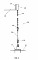
[0035] a figura 1 é uma vista lateral esquemática de uma disposição com cordas para uma BSR;[0035] figure 1 is a schematic side view of a stringed arrangement for a BSR;
[0036] a figura 2 é uma vista em perspectiva de um conector supe- rior da invenção in situ em um alpendre que se estende a partir da estrutura lateral de uma BSR;[0036] figure 2 is a perspective view of a top connector of the invention in situ on a porch that extends from the side structure of a BSR;
[0037] a figura 3 é uma vista em perspectiva do conector superior da figura 2, mas com uma unidade tensionadora removida do módulo e que também mostra um alpendre vizinho sem um conector superior;[0037] figure 3 is a perspective view of the upper connector of figure 2, but with a tensioning unit removed from the module and which also shows a neighboring porch without an upper connector;
[0038] a figura 4 é uma vista frontal do conector superior da figura 3;[0038] figure 4 is a front view of the upper connector of figure 3;
[0039] a figura 5 é uma vista lateral do conector superior das figuras 3 e 4;[0039] figure 5 is a side view of the upper connector of figures 3 and 4;
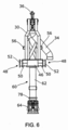
[0040] a figura 6 é uma vista frontal ampliada do conector superior mostrada na figura 3, mostrada separadamente da BSR e sem a corrente superior ou a unidade tensionadora;[0040] figure 6 is an enlarged front view of the upper connector shown in figure 3, shown separately from the BSR and without the upper chain or tensioner unit;
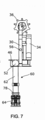
[0041] a figura 7 é uma vista lateral do conector superior da figura 6;[0041] figure 7 is a side view of the upper connector of figure 6;
[0042] a figura 8 é uma vista superior do conector superior das figuras 6 e 7;[0042] figure 8 is a top view of the upper connector of figures 6 and 7;
[0043] a figura 9 é uma vista frontal que corresponde à figura 4, mas que mostra um membro articulado pivotado em relação a uma armação que sustenta as características de controle da corrente;[0043] figure 9 is a front view corresponding to figure 4, but showing an articulated member pivoted in relation to a frame that supports the current control characteristics;
[0044] a figura 10 é uma vista lateral que corresponde à figura 9; e[0044] figure 10 is a side view corresponding to figure 9; and
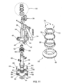
[0045] a figura 11 é uma vista explodida em perspectiva do conector superior das figuras de 6 a 10, incluindo uma vista ampliada com detalhes de uma junção flexível mostrada em círculo;[0045] figure 11 is an exploded perspective view of the upper connector of figures 6 to 10, including an enlarged view with details of a flexible joint shown in a circle;
[0046] a figura 12 é uma vista transversal ampliada com detalhes de uma parte com colar do conector superior das figuras de 6 a 10, com uma bucha anular mostrada assentada no colar e a corrente superior mostrada que se estende através da bucha;[0046] figure 12 is an enlarged cross-sectional view with details of a collar part of the upper connector of figures 6 to 10, with an annular sleeve shown seated on the collar and the upper chain shown that extends through the sleeve;
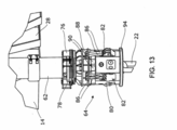
[0047] a figura 13 é uma vista em perspectiva ampliada com detalhes do mecanismo de trava da corrente sendo parte do conector superior das figuras de 2 a 10;[0047] figure 13 is an enlarged perspective view with details of the chain locking mechanism being part of the upper connector of figures 2 to 10;
[0048] a figura 14 é uma vista lateral secional do mecanismo de trava da corrente da figura 13;[0048] figure 14 is a sectional side view of the chain locking mechanism of figure 13;
[0049] a figura 15 é uma vista em perspectiva ampliada com detalhes de um mecanismo alternativo de trava de corrente que pode ser usado em um conector superior da invenção;[0049] figure 15 is an enlarged perspective view with details of an alternative chain lock mechanism that can be used in an upper connector of the invention;
[0050] a figura 16 é uma vista em perspectiva ampliada parcialmente secional com detalhes do mecanismo de trava da corrente da figura 15;[0050] figure 16 is an enlarged perspective view partially sectioned with details of the chain locking mechanism of figure 15;
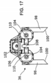
[0051] a figura 17 é uma vista superior da unidade tensionadora mostrada como parte do conector superior da figura 2 e removida do conector superior das figuras de 3 a 10;[0051] figure 17 is a top view of the tensioning unit shown as part of the upper connector of figure 2 and removed from the upper connector of figures 3 to 10;
[0052] a figura 18 é uma vista traseira da unidade tensionadora da figura 17;[0052] figure 18 is a rear view of the tensioning unit of figure 17;
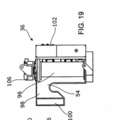
[0053] a figura 19 é uma vista lateral da unidade tensionadora das figuras 17 e 18 ;[0053] figure 19 is a side view of the tensioning unit of figures 17 and 18;
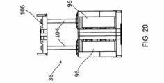
[0054] a figura 20 é uma vista traseira da unidade tensionadora das figuras de 17 a 19 que se difere da figura 18 por mostrar as hastes da unidade tensionadora se estendida;[0054] figure 20 is a rear view of the tensioning unit of figures 17 to 19 which differs from figure 18 in that it shows the rods of the tensioning unit if extended;
[0055] a figura 21 é uma vista frontal da unidade tensionadora das figuras de 17 a 20; e[0055] figure 21 is a front view of the tensioning unit of figures 17 to 20; and
[0056] a figura 22 é uma vista em perspectiva da unidade tensionadora das figuras de 17 a 21.[0056] figure 22 is a perspective view of the tensioning unit of figures 17 to 21.
[0057] A figura 1 dos desenhos coloca a invenção em contexto. Ela mostra esquematicamente um canto inferior de uma BSR 10 que possui um conector superior 12 montado do lado da estrutura lateral de uma BSR 10 perto da sua borda inferior. Através do conector superior 12, a BSR 10 é presa contra a sua flutuabilidade através da corda 16 que se estende até um alicerce 18 tal como uma pilha incorporada no leito marinho 20.[0057] Figure 1 of the drawings puts the invention in context. It schematically shows a bottom corner of a
[0058] A corda 16 compreende uma corrente superior 22, um comprimento de SSW 24 (o qual possui tipicamente milhares de metros em comprimento, como é mostrada aqui altamente abreviada), e grilhetas 26 que se juntam à corrente superior 22 no SSW 24 e no SSW 24 no alicerce 18.[0058] The
[0059] Na prática, a BSR 10 será presa por múltiplas cordas 16 (tipicamente oito cordas dispostas em quatro pares) e terá um número correspondente de conectores superiores 12 distribuídos em torno de sua estrutura lateral 14.[0059] In practice, the
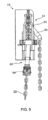
[0060] A figura 2 mostra o conector superior 12 em uma vista geral, montado do lado da estrutura lateral 14 de uma BSR 10 e sendo encaixado na corrente superior 22 da corda 16. O conector superior 12 é mostrado aqui sustentado por um alpendre 28 que se estende lateralmente a partir da estrutura lateral 14 perto da sua borda inferior.[0060] Figure 2 shows the
[0061] O conector superior 12 compreende uma armação 30 que se apoia no alpendre 28. Em sua extremidade superior, a armação 30 sustenta uma roldana com polia 32 e uma calha tubular 34 para encaminhar e gerir uma parte traseira normalmente não tensionadora da corrente superior 22. A roldana 32 gira em relação à armação 30 em torno de um eixo geométrico horizontal paralelo à estrutura lateral 14 de uma BSR 10. A armação 30 também sustenta uma unidade tensionadora 36 cooperável com a corrente superior 22, a qual permite que o conector superior 12 sirva de módulo tensionador; a unidade tensionadora 36 sendo descrita em detalhes mais adiante, com referência às figuras de 17 a 22.[0061] The
[0062] Agora, referência também é feita às figuras de 3 a 8, as quais mostram o conector superior 12 com a unidade tensionadora 36 removida, e de maneira particular à figura 3 que mostra um alpendre vizinho28 para uma corda emparelhada 16 sem um conector superior 12 no lugar. Isso mostra claramente que cada alpendre 28 compreende uma prateleira plana horizontal 38 que se estende de maneira orto- gonal para fora da estrutura lateral 14 de uma BSR 10. A prateleira 38 possui um corte central 40 na sua borda externa, com os lados do corte 40 sendo alargados para um fácil atracamento do conector superior 12 com o alpendre 28. A prateleira 38 é sustentada em ambos os lados por um par de tramas verticais 42 que também se estende para fora da estrutura lateral 14. As bordas superiores das tramas 42 possuem formações de assento em forma de U 44 que se alinham com umas com as outras em um eixo geométrico horizontal paralelo à estrutura lateral 14.[0062] Now, reference is also made to figures 3 to 8, which show the
[0063] A armação 30 possui um fundo plano que se apoia na prateleira plana 38 de um alpendre 28. No seu lado externo, o fundo da armação 30 compreende um colar circular 46 cujo eixo geométrico central vertical é paralelo à estrutura lateral 14 de uma BSR 10. O colar 46 se apoia na prateleira 38 em alinhamento com o corte 40 na borda externa da prateleira 38.[0063] The
[0064] Os munhões 48 se estendem radialmente em direções opostas sobre um eixo geométrico horizontal alinhado com um diâmetro do colar 46. As figuras 3 e 5 mostram como os munhões 48 são recebidos pelas formações de assento 44 das tramas 42. Conforme melhor mostrado na figura 6, os munhões 48 possuem partes de seção em U 50 complementares às partes em forma de U das formações de assento 44 e terminam do lado de fora em olhais de suspensão 52.[0064]
[0065] Conforme melhor mostrado na figura 4, os pontos de suspensão 52 se projetam para além das tramas 42 quando um conector superior 12 é posicionado sobre um alpendre 28. Os pontos de suspensão 52 permitem que cada conector superior 12 to seja levantado e abaixado sobre o seu alpendre 28 durante a instalação de uma BSR 10. Para encaixar o conector superior 12 no alpendre 28, os munhões 50 são alinhados com as formações de assento 44 das tramas 42 e o conector superior 12 é abaixado mantendo ao mesmo tempo esse ali- nhamento. O fundo plano da armação 30 se apoia então na prateleira 38 embora ele seja travado contra movimento em relação ao alpendre 28.[0065] As best shown in figure 4, the suspension points 52 protrude beyond the
[0066] A unidade tensionadora 36 mostrada na figura 2 é então içada separadamente sobre a armação 30 do conector superior 12, onde ela é presa por um par de ganchos com aberturas para baixo 54 em seu lado interno, o qual se encaixa em um par correspondente de arrancos 56 sobre a armação 30.[0066] The
[0067] Como o colar 46 está no lado externo da armação 30, a armação 30 é calculada na parte de dentro do eixo geométrico central vertical do colar 46. A parte interna calculada da armação 30 é feita de tal modo para posicionar o eixo geométrico de rotação da roldana 32 dentro do eixo geométrico central do colar 46 a uma distância que corresponde ao raio da roldana 32. Segue que o lado externo da circunferência da roldana 32 está verticalmente acima do centro do colar 46. Consequentemente, a parte da corrente superior 22 que se estende entre a roldana 32 e o colar 46 é mantida em um eixo geométrico vertical, paralelo à estrutura lateral 14 de uma BSR. A unidade tensionadora 36 se encaixa nessa parte vertical da corrente superior 22 conforme será explicado.[0067] As
[0068] A corrente superior 22 se estende sobre a roldana 32 e a partir de lá, para baixo dentro da calha 34, a qual está sobre o lado interno da armação 30. A calha 34 é curvada e inclinada para que ela possa guiar a corrente superior 22 a partir da roldana 32 para baixo e para fora em um plano paralelo à estrutura lateral 14 de uma BSR 10, para um eixo geométrico pendurado e espaçado horizontalmente a partir da armação 30 e a partir da estrutura lateral 14. A calha 34 pode ser ajustada de maneira preferencial, por exemplo, sendo reconfigurada ou remontada para direcionar a parte traseira da corrente superior 22 em diferentes direções. Isso garante um espaço livre entre a parte traseira e uma BSR 10, entre o conector superior 12 e corda 16, dependendo da posição do conector superior 12 na estrutura lateral 14 de uma BSR 10.[0068] The
[0069] Como pode ser visto na vista superior da figura 8, o colar 46 prende uma junção flexível anular 58 que circula a corrente superior 22. As figuras 2, 6 e 7 mostram melhor que a junção flexível 58 sustenta um membro articulado 60 que compreende um tubo se estende para fora e para baixo 62, acomodado no corte 40 da prateleira 38 do alpendre 28. O tubo em declive 62 circunda a corrente superior 22 como um guia de corrente e termina em sua extremidade inferior no mecanismo de trava da corrente 64 situado abaixo do eixo geométrico pivô da junção flexível 58.[0069] As can be seen in the top view of figure 8, the
[0070] Durante atracamento do conector superior 12 com o alpendre 28, o tubo em declive 62 entra no corte 40 da prateleira 38, assistido pelos lados alargados do corte 40.[0070] During mooring of the
[0071] Como o PCT/GB2011/051223, o tubo em declive rígido e pivotalmente montado 62 constitui uma alavanca cujo propósito é fazer com que o membro articulado 60 gire em torno da junção flexível 58 em resposta às mudanças na inclinação da corrente superior 22 em relação à BSR 10.[0071] Like PCT / GB2011 / 051223, the rigid and pivotally mounted
[0072] Diferentemente do PCT/GB2011/051223, a armação 30 acima do eixo geométrico pivô da junção flexível 58 permanece em relação fixa com o alpendre 28 e consequentemente com a BSR 10. Desse modo, o membro articulado 60 gira em relação à armação 30: a armação 30 não gira com o membro articulado 60. Esse movimento giratório do membro articulado 60 em relação à armação 30 é mostrado nas figuras 9 e 10, e é vantajoso porque não existe a necessidade de acomodar o movimento angular das estruturas acima da prateleira 38 do alpendre 28. Isso significa que o eixo geométrico pivô da junção flexível 58 pode estar relativamente perto da estrutura lateral 14 de uma BSR 10 e sendo assim, o alpendre 28 não precisa se estender muito para fora da estrutura lateral 14 como na técnica anterior. Como consequência, o alpendre 28 pode ser consideravelmente menor e Consequentemente menos maciço e dispendioso.[0072] Unlike PCT / GB2011 / 051223, the
[0073] A vista explodida da figura 11 mostra a junção flexível 58 em detalhes e a figura 12 mostra uma seção transversal da junção flexível 58 com a corrente superior 22 passando por ela. A figura 12 mostra de maneira particular como a junção flexível 58 permite uma grande abertura central para a corrente superior 22, deixando um espaço livre em torno da corrente superior 22 para reduzir o desgaste e pro-mover o livre movimento angular dos elos da corrente dentro da junção flexível 58.[0073] The exploded view of figure 11 shows the flexible joint 58 in detail and figure 12 shows a cross section of the flexible joint 58 with the
[0074] A junção flexível 58 compreende uma bucha anular elastomérica e reforçada com aço 66 que se assenta em um flange de base 67 dentro do colar 46 da armação 30 e é acoplada no tubo em declive 62 do membro articulado 60. A deformação elástica da bucha 66 permite o deslocamento angular do membro articulado 60 ao mesmo tempo em que transmite a carga da corda 16 a partir do mecanismo de trava da corrente 64 e do tubo em declive 62 para a armação 30 do conector superior 12 montado sobre to alpendre 28 de uma BSR 10.[0074] The flexible joint 58 comprises an elastomeric annular bushing reinforced with
[0075] A bucha 66 é transpassada por uma porca superior 68 fixada na bucha 66 por parafusos 70 que se estendem pelo flange inferior da porca superior 68. Por sua vez, a porca superior 68 é transpassada por uma placa de travamento 72 fixada em uma face anular superior da porca superior 68 por parafusos 74. A porca superior 68 presa pela placa de travamento 72 encaixa uma rosca macho no tubo em declive 62 do membro articulado 60 para acoplar o tubo em declive 62 na bucha 66.[0075] The
[0076] As figuras 13 e 14 mostram o mecanismo de trava da corrente 64 em detalhes. A figura 13 mostra o mecanismo de trava da corrente 64 com um grampo de desencaixe por aperto 76 também visto na figura 2; mas o grampo 76 é omitido na figura 14 e em outros desenhos precedentes. A omissão do grampo 76 na figura 14 mostra mais claramente um flange 78 sobre o tubo em declive 62 no qual o grampo 76 é encaixado conforme mostrado na figura 13. Como será explicado agora, o grampo 76 atua contra o flange 78 para desencaixar o mecanismo de trava da corrente 64 da corrente superior 22, também mostrada na figura 13, mas omitida na figura 14.[0076] Figures 13 and 14 show the
[0077] O mecanismo de trava da corrente 64 compreende um suporte com gancho 80 montado sobre a extremidade inferior do tubo em declive 62. O suporte com gancho 80 é uma estrutura tubular que circula a corrente superior 22 e sustenta quatro ganchos 82 que se faceiam internamente para encaixar a corrente superior 22. Os ganchos 82 são dispostos de um modo cruciforme, em pares opostos em planos mutuamente ortogonais que se cruzam no eixo geométrico vertical central do tubo em declive 62.[0077] The
[0078] Cada gancho 82 gira em relação ao suporte com gancho 80 em torno de um respectivo pino horizontal 84. Os ganchos 82 são inclinados para girar internamente em torno dos pinos 84 por hastes emparelhadas com mola 86 que atuam sob tensão entre os ganchos 82 e um membro anular de aperto 88 que circunda o tubo em declive 62 e m cima do suporte com gancho 80. A posição de descanso dos ganchos 82 é, portanto, encaixar a corrente superior 22 e resistir ao movimento para baixo da corrente superior 22 sob tensão da corda 16 em uso; porém quando a corrente superior 22 é puxada para cima pela unidade tensionadora 36 as será explicado, os ganchos 82 giram para fora contra a inclinação das hastes 86 para permitir que a corrente superior 22 se mova pelo suporte com gancho 80. Os ganchos 82 fornecem, portanto, o mecanismo de trava da corrente 64 com uma função de catraca.[0078] Each
[0079] O membro de aperto 88 é um encaixe deslizante sobre o tubo em declive 62 a ser movido verticalmente ao longo do tubo em declive 62 em relação ao suporte com gancho 80. O membro de aperto 88 é inclinado para cima por tubos com mola 90 que atuam sob compressão entre o fundo do membro de aperto 88 e o topo do suporte com gancho 80.[0079] The clamping
[0080] Para soltar a corrente superior 22 com um movimento para baixo através do suporte com gancho 80 e a afrouxar a corda 16, o grampo de desencaixe por aperto 76 sobre o flange 78 pressiona para baixo sobre o membro de aperto 88 contra a inclinação para cima dos tubos com mola 90. À medida que o membro de aperto 88 se move mais para perto do suporte com gancho 80, as hastes com mola 86 atuam sob compressão sobre os ganchos 82 para girar os ganchos 82 para fora. Isso permite que a corrente superior 22 se mova através do suporte com gancho 80.[0080] To release the
[0081] Para sincronizar a operação da unidade tensionadora 36 e do mecanismo de trava da corrente 64, o grampo de desencaixe por aperto 76 é ativado por um elo mecânico ou hidráulico partir da unidade tensionadora 36.[0081] To synchronize the operation of the
[0082] O mecanismo de trava da corrente 64 opera em um princípio de segurança à prova de falha no qual os ganchos 82 irão se encaixar de novo automaticamente com a corrente superior 22 se a unidade tensionadora 36 soltar a corrente superior 22, seja de um modo controlado ou acidental. Além disso, mesmo se o mecanismo de trava da corrente 64 falhar, a ativação direta dos ganchos 82 é possível com a intervenção ROV.[0082] The
[0083] O alinhamento apropriado dos elos da corrente superior 22 com os ganchos 82 é assegurado pelos guias da corrente com aberturas cruciformes alinhadas no topo e no fundo do tubo em declive 62. Esses guias da corrente são melhor mostrados na figura 11, ou seja, um guia superior 92 no topo do tubo em declive 62 e uma placa de fundo 94 na parte inferior do suporte com gancho 80.[0083] The proper alignment of the links of the
[0084] Referindo-se agora às figuras 15 e 16 dos desenhos, essas mostram um modelo alternativo e atualmente preferido para o mecanismo de trava da corrente, com o número de referência 101. Números similares são usados para partes similares.[0084] Referring now to Figures 15 and 16 of the drawings, these show an alternative and currently preferred model for the chain locking mechanism, with
[0085] O mecanismo de trava da corrente 101 das figuras 15 e 16 funciona amplamente do mesmo modo que o mecanismo de trava da corrente 64 das figuras 13 e 14no qual o movimento para baixo do membro de aperto 88 afeta o movimento liberação dos ganchos 82. O mecanismo de trava da corrente 101 se difere do mecanismo de trava da corrente 64 no modo pelo qual o movimento para baixo do membro de aperto 88 é atingido.[0085] The
[0086] De maneira específica, uma ligação operada hidraulicamente 81 aplica uma força para baixo em pontos opostos diametricamente do membro de aperto 88, em lados opostos do tubo em declive 62. Para tanto, a ligação 81 compreende um elo giratório 83 que é modelado em U na vista plana, o qual possui braços 85 que envolvem o tubo em declive 62 e que são conectados em um ápice 87.[0086] Specifically, a hydraulically operated
[0087] Um pino pivô 89 se estende por cada braço 85 dentro do tubo em declive 62 para fixar o elo giratório 83 para um movimento giratório em relação ao tubo em declive 62. Os pinos pivôs 89 se apoiam em um eixo geométrico pivô que se estende diametricamente através do tubo em declive 62.[0087] A
[0088] Os pinos pivôs 89 são dispostos na parte interna das extremidades dos braços 85. Desse modo, como o elo giratório 83 gira em torno do eixo geométrico pivô, os braços 85 podem aplicar alavancagem às hastes 91 que possuem dobradiça em uma extremidade superior nas extremidades dos braços 85 e em uma extremidade inferior no membro de aperto 88.[0088] The pivot pins 89 are arranged on the inside of the ends of the
[0089] Um ativador hidráulico 93 atua entre o ápice 87 do elo giratório em forma de U 83 e um suporte 95 soldado no tubo em declive 62 diretamente acima do ápice 87. Quando ativado, o ativador 93 atua contra o suporte 95 para puxar o ápice do elo giratório 83 para cima, o que aplica uma pressão para baixo nas hastes 91 e em relação ao membro de aperto 88.[0089] A
[0090] O ativador 93 possui uma haste extensível 97 que se encaixa no ápice 87 do elo giratório 83. A haste 97 se estende por um corte no ápice 87 do elo giratório 83 e termina em um cabeçote transversal 99 que empurra a parte inferior do ápice 87.[0090]
[0091] Referindo-se finalmente às figuras de 17 a 22 dos desenhos, essas mostram uma unidade tensionadora 36 em detalhes. A unidade tensionadora 36 será normalmente habilitada e operada a partir de uma embarcação de instalação sobre a superfície, porém de acordo com a contingência, ela pode ser habilitada e operada por uma ROV.[0091] Referring finally to figures 17 to 22 of the drawings, these show a
[0092] Conforme observado acima, uma unidade tensionadora 36 é disposta para ser atracada com um conector superior 12 quando for necessário tensionar ou afrouxar a corda 16. Uma vez atracada na armação 30 de um conector superior 12, uma unidade tensionadora 36 pode ser deixada in situ para operações futuras de retensionamento ou afrouxamento. As unidades tensionadoras 36 também podem ser deixadas in situ com o propósito de ajuste da profundidade de uma BSR 10, caso no qual um conjunto de unidades tensionadoras 36 atuando em múltiplas cordas 16 irá trabalhar junto para realizar os ajustes necessários.[0092] As noted above, a
[0093] Entretanto, ma unidade tensionadora 36 não precisa ser deixada sempre in situ sobre um conector superior 12. Para evitar duplicatas e reduzir o custo, uma unidade tensionadora 36 pode ser removida de um conector superior 12 após o uso e usada novamente em outro conector superior pré-instalado 12 para tensionar ou afrouxar sua corda associada 16. O grampo de desencaixe por aperto 76 mostrado na figuras 2 e 13 também pode ser movido de um conector superior 12 para outro quando apropriado.[0093] However, a
[0094] A unidade tensionadora 36 mostrada na figuras de 17 a 22 compreende um par de cilindros hidráulicos 96 cujos eixos geométricos paralelos são verticais e alinhados com a parede lateral 14 de uma BSR 10 em uso. Os ganchos com abertura para baixo 54, mencionados anteriormente, no lado interno da unidade tensionadora 36 para atracamento com os arrancos 56 da armação 30 de um conector superior 12 são definidos pelos braços paralelos 98 que se estendem para dentro dos lados externos dos cilindros 96. Como mostrado melhor na figura 17, os braços 98 afilados para fora em plano na direção interna em virtude das faces com pontas chanfradas viradas para dentro 100. As faces com pontas chanfradas 100 ajudam no alinhamento da unidade tensionadora 36 com a armação 30 de um conector superior 12 durante o atracamento.[0094] The
[0095] O lado externo da unidade tensionadora 36 carrega um painel de controle 102 para a intervenção ROV. O painel de controle 102 compreende de maneira adequada medidores de pressão, válvulas de interdição e conexões com ligação em ponte para suprimento de energia. O painel de controle 102 ainda pode compreender uma conexão "jumper" no grampo de desencaixe por aperto 76 do mecanismo de trava da corrente 64 para sincronizar a operação da unidade tensionadora 36 e do mecanismo de trava da corrente 64. O ativador hidráulico 93 do mecanismo alternativo de trava de corrente 101 mostrado nas figuras 15 e 16 pode ser controlado de um modo similar.[0095] The external side of the
[0096] As hastes 104 se estendem em paralelo a partir dos cilindros 96 e são conectadas através de um membro com ponte horizontal 106 que se estende paralelo à parede lateral 14 de uma BSR 10 em uso. Os eixos geométricos longitudinais centrais das hastes 104 são coplanares com a corrente superior 22 onde a corrente superior 22 se estende verticalmente entre a roldana 32 e o colar 46. O membro com ponte 106 é curvado na vista plana para repousar no lado externo da corrente superior 22. No seu lado interno, o membro com ponte 106 possui um corte central 108 alinhado com a corrente superior 22 e os ganchos opostos 110, um em cada lado do corte 108.[0096]
[0097] Para conduzir a corrente superior 22 e consequentemente aumentar a tensão na corda associada 16, os ganchos 110 da unidade tensionadora 36 são encaixados na corrente superior 22 e as hastes 104 são estendidas a partir dos cilindros 96 conforme mostrado na figura 20. Eles puxam a corrente superior 22 através do mecanismo de trava da corrente 64/101, o qual opera como uma catraca de via única. Quando o membro com ponte 106 conduzido pelas hastes 104 atinge a extremidade do seu percurso, o mecanismo de trava da corrente 64/101 pega a carga à medida que as hastes 104 são levemente retraídas dentro dos cilindros 96 e os ganchos 110 da unidade tensionadora 36 são desencaixados da corrente superior 22. As hastes 104 são então retraídas mais para trás dentro dos cilindros 96 de modo que os ganchos 110 da unidade tensionadora 36 possam ser encaixados de novo mais embaixo da corrente superior 22, prontos para o próximo percurso. Esses percursos da unidade tensionadora 36 são repetidos até que a tensão requerida seja alcançada na corda 16. É possível monitorar a tensão na corda 16 monitorando-se a pressão hidráulica nos cilindros 96.[0097] To conduct the
[0098] Com todas as cordas 16 tensionadas de maneira adequada, o nível e a atitude de uma BSR 10 podem ser avaliados para determinar se algum ajuste é necessário. Caso sejam necessários alguns ajustes, os cantos de uma BSR 10 podem ser abaixados ou levantados na água golpeando-se as unidades tensionadoras 36 nas cordas apropriadas 16 de uma BSR 10 através de quantidades adicionais até que a posição e a orientação desejada sejam alcançadas.[0098] With all
[0099] Se for necessário afrouxar a corda 16, as hastes 104 serão estendidas a partir dos cilindros 96 e os ganchos 110 da unidade ten-sionadora 36 serão encaixados na corrente superior 22. Quando a unidade tensionadora 36 tiver pego a carga, os ganchos 82 do mecanismo de trava da corrente 64/101 serão liberados para soltar a corrente superior 22. As hastes 104 serão então retraídas de volta, para dentro dos cilindros 96, permitindo que o mecanismo de trava da corrente 64/101 e consequentemente o conector superior 12 movam a corrente superior 22 em um modo controlado pelos cilindros 96.[0099] If it is necessary to loosen the
[00100] Uma variante invertida da unidade tensionadora 36 é possível na qual os cilindros 96 se movem com os ganchos 110 e as hastes 104 são fixas.[00100] An inverted variant of the
[00101] A unidade tensionadora 36 possui uma resolução de comprimento com um elo e permite ancorar a configuração de comprimento da linha em uma faixa de ± 6m, permitindo tolerâncias para o comprimento e alongamento do SSW 24, grau de inclinação do leito marinho 20 e profundidade embutida do alicerce em pilha 18. A unidade tensionadora 36 fornece uma habilidade de tensionamento permanente ou temporária para instalar a BSR 10 e para substituir a corda 16, embreando-se para dentro e para fora a corrente superior 22 quando necessário.[00101] The
[00102] Uma vez que a posição e orientação finais de uma BSR 10 são alcançadas, a força hidráulica exercida pela unidade tensionadora 36 é relaxada para transferir a carga para o mecanismo de trava da corrente 64. Os ganchos 110 da unidade tensionadora 36 podem então ser desencaixados a partir da corrente associada superior 22, o que significa que a parte da corrente superior 22 acima do mecanismo de trava da corrente 64 não está mais sob tensão. Nota-se de maneira particular que a corrente superior 22 não está sob tensão quando ela sofre um deslocamento angular no nível da junção flexível 58, evitando de maneira substancial a fatiga por envergadura e problemas com desgaste naquele local.[00102] Once the final position and orientation of a
[00103] É claro que, conforme explicado previamente, a fatiga por envergadura é um risco particular nos elos mais tensionados da corrente superior 22, onde um movimento relativo é possível entre os elos contraídos pelo mecanismo de trava da corrente 64 e pelos elos vizinhos abaixo, os quais não são contraídos de modo similar. Quanto a isso, a falha causada pela fatiga por envergadura das correntes de ancoragem é um problema muito conhecido, discutido, por exemplo, em um documento apresentado na Conferência de Tecnologia Offshore de 2005 e publicado como OTC 17238. Esse documento analisa a falha dos elos da corrente perto do escovém ou do poleame de uma corrente, onde as rotações da embarcação aplicadas à corrente sob alta pré-tensão causam grandes tensões de envergadura fora do plano. O documento também propõe uma metodologia para calcular a resistência à fadiga por envergadura de tais correntes.[00103] It is clear that, as previously explained, span fatigue is a particular risk in the most tensioned links of the
[00104] Calculando a resistência à fadiga por envergadura da corrente superior 22 através da metodologia OTC 17238, a melhoria em potencial permitida pelo conector superior 12 da presente invenção é enorme.[00104] Calculating the fatigue strength of the upper current 22 using the OTC 17238 methodology, the potential improvement allowed by the
[00105] O uso de uma sustentação esférica equivalente, a qual conforme observado acima sofre com cargas com grandes seções as quais a tornam não responsiva aos movimentos micro angulares da corda 16, pode levar a uma corrente com resistência projetada à fadiga por envergadura tão curta quanto 35 anos. Isso é claramente inadequado quando o tempo de produção de um campo petrolífero submarino está tipicamente em torno de 30 anos. Em contraste, o uso de uma junção flexível 58 de acordo com a invenção aumenta a resistên- cia projetada da corrente em relação à fadiga por envergadura até um excesso de 16.000 anos. Isso significa simplesmente que a fatiga da corrente causada por falha na envergadura não é mais um problema.[00105] The use of an equivalent spherical support, which, as noted above, suffers from loads with large sections which make it unresponsive to the micro-angular movements of the
[00106] Desse modo, o conector superior 12 da invenção é projetado para manter a integridade da corrente superior 22 durante todo o tempo de produção de um campo petrolífero submarino. Durante esse tempo, o conector superior 12 deve acomodar variações dinâmicas de ângulo e variações dinâmicas de tensão nas cordas 16 devido a variações na pegada de uma BSR 10 causadas por variações na corrente oceânica e no carregamento de SCR, o que varia os ângulos da inclinação do navio e da posição das velas de uma BSR 10 e dos movimentos de arfagem de uma BSR 10 devido às variações induzidas pelas ondas no carregamento ‘jumper".[00106] In this way, the
[00107] O conector superior 12 da invenção é capaz de suportar cargas e ângulos máximos para operar em condições extremas e em cenários acidentais, incluindo uma corrente de retorno de 100 anos ou de uma falha tal como a perda da corda ou o alagamento de múltiplos compartimentos de uma BSR 10. O conector superior 12 também resiste ao torque induzido pelo SSW 24 sob tensão e pela mudança de direção de uma BSR 10, incluindo condições acidentais, porém a sua funcionalidade antimudanças repentinas não impede a articulação que acomoda a variação angular das cordas 16.[00107] The
Claims (22)
um suporte (46) que define um eixo geométrico pivô;
uma armação (30) que se estende para cima acima do suporte quando orientada para uso, a armação (30) tendo características de controle de corrente para sustentar uma parte da corrente (22) da corda em uso; e
um membro de alavanca (60, 62) que se estende abaixo do suporte quando orientado para uso, o membro de alavanca sendo conectado de maneira giratória no suporte para movimento em torno do eixo geométrico pivô;
caracterizado pelo fato de que o membro de alavanca (60, 62) é giratório em relação ao suporte e à armação (30).Upper connector (12) for a rope (16) of a floating structure with ropes, the upper connector (12) comprising:
a support (46) that defines a pivot geometric axis;
a frame (30) that extends upwards above the support when oriented for use, the frame (30) having current control characteristics to support a part of the chain (22) of the rope in use; and
a lever member (60, 62) extending below the support when oriented for use, the lever member being swiveled to the support for movement around the pivot geometric axis;
characterized by the fact that the lever member (60, 62) is rotatable in relation to the support and the frame (30).
Applications Claiming Priority (2)
| Application Number | Priority Date | Filing Date | Title |
|---|---|---|---|
| GB1120129.0 | 2011-11-22 | ||
| GB1120129.0A GB2496860B (en) | 2011-11-22 | 2011-11-22 | Tensioning and connector systems for tethers |
Publications (2)
| Publication Number | Publication Date |
|---|---|
| BRPI1105500A2 BRPI1105500A2 (en) | 2015-11-24 |
| BRPI1105500B1 true BRPI1105500B1 (en) | 2020-11-24 |
Family
ID=45475532
Family Applications (1)
| Application Number | Title | Priority Date | Filing Date |
|---|---|---|---|
| BRPI1105500-6A BRPI1105500B1 (en) | 2011-11-22 | 2011-12-13 | upper connector for a rope of a floating structure with ropes, floating structure with ropes and tensioning unit |
Country Status (6)
| Country | Link |
|---|---|
| US (1) | US9227700B2 (en) |
| EP (1) | EP2834145B1 (en) |
| AU (1) | AU2012342257B2 (en) |
| BR (1) | BRPI1105500B1 (en) |
| GB (1) | GB2496860B (en) |
| WO (1) | WO2013076461A1 (en) |
Families Citing this family (8)
| Publication number | Priority date | Publication date | Assignee | Title |
|---|---|---|---|---|
| FR2984272B1 (en) * | 2011-12-14 | 2014-06-13 | Nov Blm | CHAUMARD FOR GUIDING AN ANCHORING CHAIN FOR EQUIPPING AN ANCHORING SYSTEM ON THE GROUND OF A FLOATING PLATFORM |
| US10151151B2 (en) | 2015-04-07 | 2018-12-11 | Ensco International Incorporated | Riser deflection mitigation |
| NO339306B1 (en) * | 2015-05-04 | 2016-11-21 | Scana Offshore Vestby As | Mooring arrangment and a chain stopper assembly |
| WO2017050841A1 (en) * | 2015-09-25 | 2017-03-30 | Single Buoy Moorings Inc. | Connector arrangement for connecting a mooring line to a floating structure and floating structure comprising such a connector arrangement |
| TWI635023B (en) * | 2015-12-28 | 2018-09-11 | 塞拉馬德雷海事有限責任公司 | Chain flaker system, to distribute anchor chain evenly in anchor chain locker |
| GB2547015B (en) * | 2016-02-04 | 2021-08-25 | Balltec Ltd | Mooring connector assembly |
| CN106542451A (en) * | 2016-12-06 | 2017-03-29 | 华强方特(芜湖)文化科技有限公司 | A kind of synchronous suspention wirerope roll-setting gear |
| GB201706743D0 (en) * | 2017-04-27 | 2017-06-14 | Flintstone Tech Ltd | Mooring apparatus |
Family Cites Families (12)
| Publication number | Priority date | Publication date | Assignee | Title |
|---|---|---|---|---|
| GB860032A (en) * | 1959-01-21 | 1961-02-01 | Neill Garland | Improvements in and relating to buoys |
| US4823125A (en) * | 1987-06-30 | 1989-04-18 | Develco, Inc. | Method and apparatus for stabilizing a communication sensor in a borehole |
| US5951061A (en) * | 1997-08-13 | 1999-09-14 | Continental Emsco Company | Elastomeric subsea flex joint and swivel for offshore risers |
| GB2351058A (en) | 1999-06-17 | 2000-12-20 | Bluewater Terminal Systems Nv | Chain attachment apparatus |
| US6835025B1 (en) * | 2001-09-21 | 2004-12-28 | Rti Energy Systems, Inc. | Receptacle assembly and method for use on an offshore structure |
| US6663320B1 (en) * | 2002-09-25 | 2003-12-16 | Single Buoy Moorings Inc. | Anchor line connector |
| US7240633B2 (en) * | 2004-04-30 | 2007-07-10 | Timberland Equipment Limited | Underwater chain stopper and fairlead apparatus for anchoring offshore structures |
| US7325508B2 (en) * | 2005-03-24 | 2008-02-05 | Sofec, Inc. | Dual-axis chain support assembly |
| BRPI0807489A2 (en) * | 2007-02-12 | 2014-05-20 | Single Buoy Moorings | STEEL PIPE FLUID TRANSFER SYSTEM |
| US7926436B2 (en) * | 2009-01-15 | 2011-04-19 | Sofec Inc. | Dual axis chain support with chain pull through |
| NO330879B1 (en) * | 2009-01-23 | 2011-08-08 | I P Huse As | Device by fairlead |
| GB2481787A (en) | 2010-06-29 | 2012-01-11 | Subsea 7 Ltd | A method and apparatus for installing a buoy to an anchoring location |
-
2011
- 2011-11-22 GB GB1120129.0A patent/GB2496860B/en active Active
- 2011-12-13 BR BRPI1105500-6A patent/BRPI1105500B1/en active IP Right Grant
-
2012
- 2012-11-15 WO PCT/GB2012/052833 patent/WO2013076461A1/en active Application Filing
- 2012-11-15 AU AU2012342257A patent/AU2012342257B2/en active Active
- 2012-11-15 EP EP12806085.2A patent/EP2834145B1/en active Active
- 2012-11-15 US US14/360,259 patent/US9227700B2/en active Active
Also Published As
| Publication number | Publication date |
|---|---|
| EP2834145A1 (en) | 2015-02-11 |
| US9227700B2 (en) | 2016-01-05 |
| WO2013076461A1 (en) | 2013-05-30 |
| EP2834145B1 (en) | 2016-04-27 |
| GB2496860B (en) | 2014-03-19 |
| AU2012342257B2 (en) | 2015-05-07 |
| BRPI1105500A2 (en) | 2015-11-24 |
| US20150000579A1 (en) | 2015-01-01 |
| AU2012342257A1 (en) | 2014-06-05 |
| GB201120129D0 (en) | 2012-01-04 |
| GB2496860A (en) | 2013-05-29 |
Similar Documents
| Publication | Publication Date | Title |
|---|---|---|
| BRPI1105500B1 (en) | upper connector for a rope of a floating structure with ropes, floating structure with ropes and tensioning unit | |
| US5263796A (en) | Self-closing clamping apparatus | |
| BR112017015372B1 (en) | SUBSEA WELL HEAD ASSEMBLY AND INSTALLATION METHOD OF A SUBSEA WELL HEAD ASSEMBLY | |
| BR102012003065B1 (en) | tensioner to maintain a tensile force in a riser and method to tension a riser | |
| BR112018068061B1 (en) | SUBMARINE WELL HEAD ASSEMBLY | |
| BR112012032886B1 (en) | DEVICE AND METHOD FOR STABILIZING A WELL HEAD AND USING A SUCTION SUBSTRUCTURE | |
| BR102012000488A2 (en) | tensioning apparatus for tensioning a lash extending between a first frame and a second frame | |
| CN113316539A (en) | Yoke plate assembly for mooring device and mooring device comprising same | |
| US4893965A (en) | System for offshore operations | |
| US9567040B2 (en) | Tension-leg platform anchoring system | |
| BR112016020106B1 (en) | method of handling an elongated subsea element transport, subsea installation, surface vessel, submersible tractor and elongated subsea element | |
| BR112015020594B1 (en) | INSTALLATION PROCESS OF AN Elongated ELEMENT IN A WATER EXTENSION, INSTALLATION DEVICE OF AN Elongated ELEMENT IN A WATER EXTENSION AND INSTALLATION | |
| BRPI0810367B1 (en) | CHAIN CONNECTION APPLIANCE AND METHOD FOR TIING AN OBJECT TO THE SEA BED | |
| BR112012029445B1 (en) | installation of bottom-to-surface connection and offshore towing method of a tower | |
| US9422773B2 (en) | Relating to buoyancy-supported risers | |
| US8152411B2 (en) | Guide arrangement | |
| BR102012028501A2 (en) | TENSOR AND METHOD | |
| BR102012002384B1 (en) | CONNECTOR FOR USE WITH A SUBMARINE RISER INSTALLATION, RISER INSTALLATION AND METHOD OF SUPPLYING A RELIEF JOINT FOR A RISER INSTALLATION | |
| BR112019019215A2 (en) | connector for connecting subsea well assembly components and connection method | |
| US20160376854A1 (en) | Methods and systems for tensioner connection | |
| NO329901B1 (en) | Support system for an offshore construction | |
| AU2022222915A1 (en) | Subsea foundations | |
| BR112020014496A2 (en) | set and method for offshore drilling rig | |
| GB2069566A (en) | Production riser | |
| BR112019024064A2 (en) | METHOD AND SYSTEM FOR FITTING AN SUBMARINE PIPING |
Legal Events
| Date | Code | Title | Description |
|---|---|---|---|
| B03A | Publication of an application: publication of a patent application or of a certificate of addition of invention | ||
| B25G | Requested change of headquarter approved |
Owner name: SUBSEA 7 LIMITED (GB) |
|
| B25G | Requested change of headquarter approved |
Owner name: SUBSEA 7 LIMITED (GB) |
|
| B06F | Objections, documents and/or translations needed after an examination request according art. 34 industrial property law | ||
| B06U | Preliminary requirement: requests with searches performed by other patent offices: suspension of the patent application procedure | ||
| B09A | Decision: intention to grant | ||
| B16A | Patent or certificate of addition of invention granted |
Free format text: PRAZO DE VALIDADE: 20 (VINTE) ANOS CONTADOS A PARTIR DE 13/12/2011, OBSERVADAS AS CONDICOES LEGAIS. |