BRPI1104015B1 - apparatus for manufacturing a fibrous article formed having a three-dimensional profile - Google Patents
apparatus for manufacturing a fibrous article formed having a three-dimensional profile Download PDFInfo
- Publication number
- BRPI1104015B1 BRPI1104015B1 BRPI1104015-7A BRPI1104015A BRPI1104015B1 BR PI1104015 B1 BRPI1104015 B1 BR PI1104015B1 BR PI1104015 A BRPI1104015 A BR PI1104015A BR PI1104015 B1 BRPI1104015 B1 BR PI1104015B1
- Authority
- BR
- Brazil
- Prior art keywords
- cylinder
- vacuum
- vacuum chamber
- area
- rotating cylinder
- Prior art date
Links
Images


Classifications
-
- A—HUMAN NECESSITIES
- A61—MEDICAL OR VETERINARY SCIENCE; HYGIENE
- A61F—FILTERS IMPLANTABLE INTO BLOOD VESSELS; PROSTHESES; DEVICES PROVIDING PATENCY TO, OR PREVENTING COLLAPSING OF, TUBULAR STRUCTURES OF THE BODY, e.g. STENTS; ORTHOPAEDIC, NURSING OR CONTRACEPTIVE DEVICES; FOMENTATION; TREATMENT OR PROTECTION OF EYES OR EARS; BANDAGES, DRESSINGS OR ABSORBENT PADS; FIRST-AID KITS
- A61F13/00—Bandages or dressings; Absorbent pads
- A61F13/15—Absorbent pads, e.g. sanitary towels, swabs or tampons for external or internal application to the body; Supporting or fastening means therefor; Tampon applicators
- A61F13/15577—Apparatus or processes for manufacturing
- A61F13/15707—Mechanical treatment, e.g. notching, twisting, compressing, shaping
- A61F13/15731—Treating webs, e.g. for giving them a fibrelike appearance, e.g. by embossing
-
- A—HUMAN NECESSITIES
- A61—MEDICAL OR VETERINARY SCIENCE; HYGIENE
- A61F—FILTERS IMPLANTABLE INTO BLOOD VESSELS; PROSTHESES; DEVICES PROVIDING PATENCY TO, OR PREVENTING COLLAPSING OF, TUBULAR STRUCTURES OF THE BODY, e.g. STENTS; ORTHOPAEDIC, NURSING OR CONTRACEPTIVE DEVICES; FOMENTATION; TREATMENT OR PROTECTION OF EYES OR EARS; BANDAGES, DRESSINGS OR ABSORBENT PADS; FIRST-AID KITS
- A61F13/00—Bandages or dressings; Absorbent pads
- A61F13/15—Absorbent pads, e.g. sanitary towels, swabs or tampons for external or internal application to the body; Supporting or fastening means therefor; Tampon applicators
- A61F13/45—Absorbent pads, e.g. sanitary towels, swabs or tampons for external or internal application to the body; Supporting or fastening means therefor; Tampon applicators characterised by the shape
- A61F13/47—Sanitary towels, incontinence pads or napkins
- A61F13/472—Sanitary towels, incontinence pads or napkins specially adapted for female use
- A61F13/47218—Sanitary towels, incontinence pads or napkins specially adapted for female use with a raised crotch region, e.g. hump
Abstract
APARELHO PARA PRODUZIR UM ARTIGO FIBROSO TENDO UM PERFIL TRIDIMENSIONAL. A presente invenção refere-se, de modo geral, a um método e aparelho para a produção de um artigo fibroso formado e, mais especificamente, a um método e aparelho para a fabricação de um artigo fibroso formado útil, como uma estrutura de núcleo absorvente, em um artigo sanitário descartável como um absorvente higiênico, protetor de calcinha, fralda ou similares. A presente invenção também se refere a um artigo sanitário descartável incluindo um artigo fibroso formado de acordo com a presente invenção como um estrutura de núcleo do mesmo.APPARATUS TO PRODUCE A FIBROUS ITEM WITH A THREE-DIMENSIONAL PROFILE. The present invention relates generally to a method and apparatus for producing a formed fibrous article and, more specifically, to a method and apparatus for manufacturing a useful formed fibrous article, such as an absorbent core structure , in a disposable sanitary article such as a sanitary napkin, panty protector, diaper or similar. The present invention also relates to a disposable sanitary article including a fibrous article formed in accordance with the present invention as a core structure thereof.
Description
[0001] A presente invenção refere-se, de modo geral, a um método e aparelho para a produção de um artigo fibroso formado e, mais especificamente, a um método e aparelho para fazer um artigo fibroso formado útil, como uma estrutura de núcleo absorvente, em um artigo sanitário descartável como um absorvente higiênico, protetor de calcinha, fralda ou similares. A presente invenção também se refere a um artigo sanitário descartável incluindo um artigo fibroso formado de acordo com a presente invenção como uma estrutura de núcleo do mesmo.[0001] The present invention relates, in general, to a method and apparatus for producing a formed fibrous article and, more specifically, to a method and apparatus for making a formed fibrous article useful, as a core structure absorbent, in a disposable sanitary article such as a sanitary napkin, panty protector, diaper or similar. The present invention also relates to a disposable sanitary article including a fibrous article formed in accordance with the present invention as a core structure thereof.
[0002] Vários métodos para fazer artigos fibrosos formados a partir de materiais fibrosos como celulose ou similares são bem conhecidos daqueles versados na técnica. Um método comum para a fabricação de tais artigos fibrosos formados consiste desfibrar um material de partida e, então, criar um fluxo arrastado por ar do material desfibrado. O material desfibrado arrastado por ar pode ser moldado em um artigo fibroso formado através do uso de uma estrutura de molde poroso submetida a vácuo para atrair o material desfibrado para o molde.[0002] Various methods for making fibrous articles formed from fibrous materials such as cellulose or the like are well known to those skilled in the art. A common method for making such formed fibrous articles is to defibrate a starting material and then create an air entrained flow of the defibrated material. The defibrated air entrained material can be molded into a fibrous article formed using a porous mold structure subjected to vacuum to attract the defibrated material to the mold.
[0003] É fato conhecido, ainda, que artigos fibrosos formados do tipo descrito acima podem ser submetidos a processos de calandragem para alterar as propriedades de manuseio mecânicas e de fluidos de tais artigos. Um processo de calandragem usado na técnica é comumente denominado "calandragem por pinos". A calandragem por pinos emprega uma pluralidade de pinos adaptados para comprimir e densificar o artigo.[0003] It is also known that fibrous articles formed of the type described above can be subjected to calendering processes to alter the mechanical and fluid handling properties of such articles. A calendering process used in the art is commonly called "pin calendering". Pin calendering employs a plurality of pins adapted to compress and densify the article.
[0004] Um problema associado com os processos de calandragempor pinos do tipo descrito acima é tal que tais processos exigem tipicamente que uma "camada de suporte" seja usada durante a etapa de calandragem por pinos. O termo "camada de suporte" para uso na presente invenção significa qualquer camada de material usado para suportar o artigo fibroso formado, como uma esteira transportadora ou uma camada de material adjacente, tal como uma camada de não tecido enrolada ou similares. O uso de tal camada de suporte aumenta a complexidade de fabricação. Além disso, se a camada de suporte for uma camada destinada a ser incorporada no produto final, a inclusão de tal camada pode aumentar o custo final do produto e/ou afeta indesejavelmente as características de manuseio de fluidos do produto.[0004] A problem associated with pin calendering processes of the type described above is such that such processes typically require that a "backing layer" be used during the pin calendering step. The term "support layer" for use in the present invention means any layer of material used to support the formed fibrous article, such as a conveyor belt or a layer of adjacent material, such as a rolled nonwoven layer or the like. The use of such a support layer increases the manufacturing complexity. In addition, if the backing layer is a layer intended to be incorporated into the final product, the inclusion of such a layer may increase the final cost of the product and / or undesirably affect the fluid handling characteristics of the product.
[0005] Em vista do exposto, os inventores da presente invenção descobriram e apresentaram aqui um método e um aparelho para fazer um artigo fibroso formado preparado por calandragem por pinos que não exige o uso de uma camada de suporte. Os artigos fibrosos formados de acordo com a presente invenção são particularmente úteis como uma estrutura de núcleo absorvente em um artigo sanitário descartável como um absorvente higiênico, um protetor de calcinha, fralda ou similares.[0005] In view of the foregoing, the inventors of the present invention have discovered and presented here a method and apparatus for making a formed fibrous article prepared by pin calendering that does not require the use of a backing layer. The fibrous articles formed in accordance with the present invention are particularly useful as an absorbent core structure in a disposable sanitary article such as a sanitary napkin, a panty protector, diaper or the like.
[0006] Em vista do exposto, a presente invenção apresenta um aparelho para fazer um artigo fibroso formado que tem um perfil tridimensional, o aparelho incluindo uma estação de calandragem que inclui um primeiro cilindro e um segundo cilindro, na qual o segundo cilindro inclui pelo menos uma reentrância para fornecer um artigo fibroso formado com um perfil tridimensional, uma estação de calandragem por pinos que inclui um primeiro cilindro e um segundo cilindro, sendo que o primeiro cilindro e o segundo cilindro são estruturados e dispostos para transportar um artigo fibroso através de um estrangulamento definido entre o primeiro e o segundo cilindros sem o uso de uma camada de suporte.[0006] In view of the foregoing, the present invention features an apparatus for making a formed fibrous article having a three-dimensional profile, the apparatus including a calendering station that includes a first cylinder and a second cylinder, in which the second cylinder includes at least at least one recess to provide a fibrous article formed with a three-dimensional profile, a pin calendering station that includes a first cylinder and a second cylinder, the first cylinder and the second cylinder being structured and arranged to transport a fibrous article through a definite choke between the first and second cylinders without the use of a support layer.
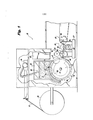
[0007] Exemplos de modalidades da presente invenção serão agora descritos com referência aos desenhos, onde:A figura 1 é uma vista em elevação lateral de um aparelho de acordo com a presente invenção;A figura 2 é uma vista em perspectiva detalhada do tambor de formação que faz parte do aparelho de acordo com a presente invenção;A figura 3 é uma vista em corte tomada ao longo da linha 3- 3 na figura 2;A figura 4 é uma vista em perspectiva detalhada de uma porção do tambor de formação mostrado na figura 2;A figura 5 é uma vista em elevação lateral do tambor de formação e da estação de calandragem que faz parte do aparelho de acordo com a presente invenção;A figura 6 é uma vista em perspectiva detalhada da estação de calandragem mostrada na figura 5, representando o cilindro de vácuo e o cilindro de calandra do mesmo;A figura 7 é uma vista em elevação daquela porção do cilindro de calandra da estação de calandragem circulada na figura 6;A figura 8 é uma vista em corte tomada ao longo da linha 8- 8 na figura 6;A figura 9 é uma vista em perspectiva detalhada daquela porção do cilindro de vácuo da estação de calandragem circulada na figura 6;A figura 10 é uma vista em perspectiva de um artigo fibroso formado de acordo com a invenção após passar pela estação de calandragem;A figura 11 é uma vista em elevação lateral de uma estação de calandragem por pinos que faz parte do aparelho de acordo com apresente invenção;Afigura 12 é uma vista em perspectiva detalhada da estação de calandragem por pinos mostrada na figura 11, representando o cilindro de vácuo e o cilindro de calandra por pinos do mesmo;A figura 13 é uma vista em perspectiva parcialmente explodida do cilindro de calandra por pinos da estação de calandragem por pinos;A figura 14 é uma vista em planta detalhada daquela porção do cilindro de calandra por pinos circulado na figura 13;A figura 15 é uma vista em corte tomada ao longo da linha 15-15 na figura 14;A figura 16 é uma vista em perspectiva detalhada daquela porção do cilindro de calandra por pinos circulada na figura 13;A figura 17 é uma vista em corte tomada ao longo da linha 17-17 na figura 11;A figura 18 é uma vista em corte tomada ao longo da linha 18-18 na figura 12;A figura 19 é uma vista em elevação lateral de uma roda de transferência que faz parte do aparelho de acordo com a presente invenção;Afigura 20 é uma vista em perspectiva detalhada da roda de transferência mostrada na figura 19;A figura 21 é uma vista em planta superior do artigo fibroso formado após passar pela estação de calandragem por pinos;A figura 22 é uma vista em perspectiva detalhada da porção do artigo fibroso formado circulada na figura 21;A figura 23 é uma vista em perspectiva de um artigo absorvente de acordo com a presente invenção com a camada de cobertura e sua camada de transferência parcialmente decompostas;A figura 24 é uma vista em corte ao longo da linha 24-24 nafigura 23; eAs figuras 25 a 26 são vistas em perspectiva de modalidades alternativas de artigos absorventes de acordo com a presente invenção.[0007] Examples of embodiments of the present invention will now be described with reference to the drawings, where: Figure 1 is a side elevation view of an apparatus according to the present invention; Figure 2 is a detailed perspective view of the drum. forming part of the apparatus according to the present invention; figure 3 is a sectional view taken along line 3- 3 in figure 2; figure 4 is a detailed perspective view of a portion of the training drum shown in figure 2; figure 5 is a side elevation view of the forming drum and the calendering station that is part of the apparatus according to the present invention; figure 6 is a detailed perspective view of the calendering station shown in the figure 5, representing the vacuum cylinder and the calender cylinder thereof; Figure 7 is an elevation view of that portion of the calender cylinder of the calendering station circled in figure 6; Figure 8 is a sectional view taken along the l line 8- 8 in figure 6; figure 9 is a detailed perspective view of that portion of the vacuum cylinder of the calendaring station circled in figure 6; figure 10 is a perspective view of a fibrous article formed according to the invention after passing through the calendering station; Figure 11 is a side elevation view of a pin calendering station that is part of the apparatus according to the present invention; Figure 12 is a detailed perspective view of the pin calendering station shown in figure 11, representing the vacuum cylinder and the pin calender cylinder; Figure 13 is a partially exploded perspective view of the pin calender cylinder of the pin calender station; Figure 14 is a detailed plan view of that portion of the pin calender cylinder circled in figure 13; figure 15 is a sectional view taken along line 15-15 in figure 14; figure 16 is a detailed perspective view of that by of the pin calender cylinder circled in figure 13; figure 17 is a sectional view taken along line 17-17 in figure 11; figure 18 is a sectional view taken along line 18-18 in figure 12; Figure 19 is a side elevation view of a transfer wheel that forms part of the apparatus according to the present invention; Figure 20 is a detailed perspective view of the transfer wheel shown in figure 19; Figure 21 is a top plan view of the fibrous article formed after passing through the pin calendering station; figure 22 is a detailed perspective view of the portion of the formed fibrous article circled in figure 21; figure 23 is a perspective view of an absorbent article of according to the present invention with the cover layer and its transfer layer partially decomposed; Figure 24 is a sectional view along line 24-24 in figure 23; Figures 25 to 26 are seen in perspective of alternative embodiments of absorbent articles according to the present invention.
[0008] Com referência às figuras 1 a 9 e 11 a 20, é ilustrado um aparelho 10 preferencial para fazer um artigo fibroso formado 12 de acordo com o método da presente invenção.[0008] With reference to figures 1 to 9 and 11 to 20, a preferred apparatus 10 for making a fibrous article formed 12 according to the method of the present invention is illustrated.
[0009] Conforme mostrado na figura 1, o aparelho 10 de acordo com a presente invenção inclui geralmente um tambor de formação 14, uma estação de calandragem 16, uma estação de calandragem por pinos 18, e uma roda de transferência 20. Determinados detalhes do aparelho 10, como linhas elétricas, foram omitidos das figuras para simplificá-lo. Entretanto, estas características e outros elementos básicos do aparelho serão claros para os versados na técnica.[0009] As shown in figure 1, the apparatus 10 according to the present invention generally includes a forming
[00010] O artigo fibroso formado 12 que é mostrado durante os vários estágios do método de acordo com a presente invenção nas figuras 3, 5-6, 8, 10, 12 e 18-22 é formado, de preferência, a partir de fibras celulósicas, e em uma modalidade preferencial da invenção, inclui uma mistura de fibras celulósicas e polímero superabsorvente. Fibras celulósicas que podem ser usadas no artigo fibroso formado 12 são bem conhecidas na técnica e incluem polpa de madeira, algodão, linho e musgo de turfa. Polpa de madeira é preferencial. Tanto espécies de madeira macia como de madeira de lei são úteis. Polpas de madeira macia são preferenciais.[00010] The fibrous article formed 12 which is shown during the various stages of the method according to the present invention in figures 3, 5-6, 8, 10, 12 and 18-22 is preferably formed from fibers cellulosic, and in a preferred embodiment of the invention, includes a mixture of cellulosic fibers and superabsorbent polymer. Cellulosic fibers that can be used in the formed
[00011] O artigo fibroso 12 pode conter, também, qualquer polímero superabsorvente (SAP) bem conhecido na técnica. Para os propósitos da presente invenção, o termo "polímero superabsorvente" (ou "SAP") refere-se a materiais que são capazes de absorver e reter pelo menos cerca de 10 vezes seu peso em fluidos corpóreos, sob uma pressão de 3,45 kPa (0,5 psi). As partículas de polímero superabsorvente dainvenção podem ser polímeros hidrofílicos reticulados inorgânicos ou orgânicos, como alcoóis polivinílicos, óxidos de polietileno, amidos reticulados, goma guar, gomas xantanas, e similares. As partículas podem estar sob a forma de pó, grãos, grânulos, ou fibras. As partículas de polímero superabsorvente preferenciais para uso na presente invenção são poliacrilatos reticulados, como o produto disponível junto à Sumitomo Seika Chemicals Co., Ltd. de Osaka, Japão, sob a designação SA70N, e os produtos disponíveis junto à Stockhausen Inc.[00011] The
[00012] A polpa usada para formar o artigo fibroso 12 é, de preferência, uma polpa de madeira macia alvejada produzida por um processo Kraft. Conforme mostrado na figura, a polpa é fornecida pelo fabricante sob a forma de uma placa de polpa 22 enrolada em cilindros, o cilindro sendo identificado pelo número de referência 24. A placa de polpa 22 é transportada do cilindro 24 para um dispositivo 26 para trituração da placa de polpa 22 em polpa fibrosa 28. A polpa fibrosa 28 é liberada pelo dispositivo triturador 26 para dentro de uma câmara 30 destinada a conter a polpa fibrosa 28. O aparelho 10 pode, ainda, incluir opcionalmente um dispositivo 32 para introdução de polímero superabsorvente na câmara 30, para assim formar uma mistura de polpa fibrosa com superabsorvente. Qualquer dispositivo convencional adequado a esse propósito e conhecido pelos versados na técnica pode ser usado para introduzir o superabsorvente na câmara 30.[00012] The pulp used to form the
[00013] Conforme se pode observar melhor na figura 3, a câmara 30 tem uma porção inferior parcialmente aberta 34 que se comunica com o tambor de formação 14. Conforme visto na figura 1, o tambor de formação 14 inclui um cilindro oco 15 que é estruturado e disposto para girarem torno de um eixo fixo 17. Qualquer meio convencional para girar o cilindro 15, bem conhecido daqueles versados na técnica, pode ser usado para girar o cilindro 15. Conforme mostrado nas figuras 1 a 4, o cilindro 15 tem uma pluralidade de moldes 36 instalados a ele. Conformeo cilindro 15 gira, cada um dos moldes 36 é disposto sequencialmente em comunicação com a porção aberta 34 da câmara 30 para, assim, receber a polpa fibrosa 28 proveniente da câmara 30. Na figura 1, o cilindro 15 gira em sentido anti-horário durante o funcionamento do aparelho 10.[00013] As can be seen better in figure 3, the
[00014] Conforme mostrado nas figuras 1 e 3, o tambor de formação 14 inclui adicionalmente uma câmara de vácuo 38 disposta no interior do cilindro 15. A câmara de vácuo 38 está disposta em um local fixo em relação ao cilindro giratório 15 e está acoplado operacionalmente a uma fonte de vácuo (não mostrada). Conforme se pode observar melhor na figura 4, o molde 36 inclui uma estrutura em tela porosa 40 no formato do artigo fibroso formado 12 a ser formado no molde 36. Conforme o molde 36 passa ao longo da câmara de vácuo 38 do tambor de formação 14 o vácuo funciona de modo a atrair a polpa fibrosa 28 da câmara 30 para dentro do molde 36 ao extrair ar através da tela porosa 40 do molde 36.[00014] As shown in figures 1 and 3, the forming
[00015] Conforme mostrado em detalhes na figura 4, o molde 36 inclui uma porção de placa de suporte não porosa 42 que circunda a porção de tela porosa 40 do molde 36. A porção de placa de suporte 42 do molde 36 está instalada na periferia 44 do cilindro 15, permitindo assim que cada um dos moldes 36 gire com o cilindro giratório 15.[00015] As shown in detail in figure 4, the
[00016] Após o molde 36 ser girado sob a porção inferior parcialmente aberta 34 da câmara 30, o molde 36 é ainda girado pelo cilindro giratório 15, e conforme descrito em mais detalhes abaixo, o artigo fibroso 12 é então transferido para a estação de calandragem 16.[00016] After the
[00017] Após a formação no molde 36, o artigo fibroso formado 12 tem, de preferência, uma base ponderai na faixa entre cerca de 200 gsm (g/m2) a cerca de 400 g/m2, uma espessura na faixa de cerca de 5 mm a cerca de 20 mm, e uma densidade na faixa de cerca de 0,01 g/cc a cerca de 0,03 g/cc.[00017] After forming in the
[00018] Conforme mostrado nas figuras 1 e 5 a 9, a estação de calandragem 16 inclui geralmente um cilindro de vácuo 42 e um cilindro de calandra oposto 44. Conforme se pode observar melhor na figura 6, o cilindro de vácuo 42 é formado a partir de um cilindro giratório 46 que pode girar em torno de um eixo fixo 48. O cilindro de calandra 44 pode girar em torno de um eixo fixo 49. Quaisquer meios convencionais para girar o cilindro 46, e o cilindro de calandra 44, bem conhecidos daqueles versados na técnica, podem ser usados para girar o cilindro 46 e o cilindro de calandra 44. O cilindro 46 gira em sentido horário durante o funcionamento do aparelho 10, e o cilindro de calandra 44 gira em sentido anti-horário, conforme mostrado na figura 1. Conforme se pode observar melhor nas figuras 6, 8 e 9, o cilindro 46 inclui uma pluralidade de orifícios 50 que se estendem da superfície externa 52 do cilindro 46 para a superfície interna 54 do cilindro 46.[00018] As shown in figures 1 and 5 to 9, the
[00019] Conforme mostrado em detalhes na figura 7, a superfície 47 do cilindro de calandra 44 inclui uma reentrância 53. A reentrância 53 pode assumir qualquer quantidade de formatos diferentes incluindo genericamente oval, elíptico, circular ou similares. Em uma modalidade preferencial da invenção, conforme mostrado na figura 7, a reentrância tem, geralmente, um formato oval. De preferência, a reentrância 53 se estende ao longo de uma área superficial na faixa de cerca de 500 mm2 a cerca de 5000 mm2. A reentrância 53 tem, de preferência, uma profundidade na faixa de cerca de 2 mm a cerca de 25 mm como medido a partir da superfície 47 do cilindro 44 localizado fora da reentrância 53. A reentrância 53 está disposta, de preferência, de modo a ser mais longa na direção da máquina (md) do que na direção transversal (td). De preferência, a reentrância 53 tem um comprimento máximo, conforme medido na direção da máquina, na faixa de cerca de 20 mm a cerca de 120 mm e uma largura máxima, conforme medido na direção transversal, na faixa de cerca de 5 mm a cerca de 60 mm.[00019] As shown in detail in figure 7, the
[00020] Conforme mostrado nas figuras 5, 6 e 8, o cilindro de vácuo 42 inclui adicionalmente uma câmara de vácuo 56 disposta no interior do cilindro 46. A câmara de vácuo 56 está disposta em um local fixo em relação ao cilindro giratório 46 e está operacional mente acoplada a uma fonte de vácuo 57 (figura 1). A câmara de vácuo 56 está disposta em comunicação fluida com a pluralidade de orifícios 50 que se estendem através do cilindro 46 e, assim, extrai ar através dos ditos orifícios 50.[00020] As shown in figures 5, 6 and 8, the
[00021] Conforme mostrado na figura 5, a câmara de vácuo 56 está disposta de modo que sua borda anterior 58 esteja substancialmente alinhada com uma borda posterior 60 da câmara de vácuo 38 localizada no interior do cilindro 15 do tambor de formação 14. Esta disposição da câmara de vácuo 56 em relação ao local da câmara de vácuo 38 faz uma transferência do artigo fibroso formado 12 de dentro do molde 36 no tambor de formação 14 para o cilindro de vácuo 42.[00021] As shown in figure 5, the vacuum chamber 56 is arranged so that its
[00022] Uma vez que o artigo fibroso formado 12 foi transferido para o cilindro 46 do cilindro de vácuo 42 o cilindro 46 gira o artigo fibroso 12 até ele 12 passar através do estrangulamento 62 formado entre o cilindro de vácuo 42 e o cilindro de calandra 44. O estrangulamento 62 comprime, de preferência, uniformemente, o artigo fibroso 12 fora da área definida pela reentrância 53. A compactação do artigo fibroso 12 resulta em uma redução na espessura do artigo 12 e um aumento correspondente na densidade naquela porção do artigo fibroso 12 localizada fora da área da reentrância 53. Em uma modalidade preferencial da invenção, o estrangulamento 62 tem uma distância "d" (isto é, a distância entre as superfícies dos cilindros opostos) de cerca de 0,9 mm. A distância "d" é identificada pelo símbolo de referência "d" na figura 8.[00022] Once the formed
[00023] Conforme mostrado na figura 10, após passar pelo estrangulamento 62 o artigo fibroso 12 inclui, geralmente, duas áreas 59 e 61. A primeira área 59, corresponde a porção do artigo 12 que foicomprimida pelos cilindros 42 e 44 fora da área da reentrância 53. A área 59 se estende, de preferência, ao longo de uma área superficial entre cerca de 7000 mm2e 14000 mm2, tem uma espessura na faixa de cerca de 4 mm a cerca de 12 mm, e uma densidade na faixa de cerca de 0,02 g/cc a cerca de 0,1 g/cc. A área 61 do artigo 12 é a porção do artigo 12 que corresponde ao local da reentrância 53. A área 61 se estende, de preferência, ao longo de uma área superficial de cerca de 1000 mm2 a 7000 mm2, tem uma espessura na faixa de cerca de 10 mm a cerca de 20 mm, e uma densidade na faixa de cerca de 0,01 g/cc a cerca de 0,04 g/cc.[00023] As shown in figure 10, after passing through the
[00024] Observa-se que o artigo fibroso 12, após passar pelo estrangulamento 62, tem um perfil tridimensional. Especificamente, a área 59 do artigo fibroso define uma porção substancialmente plana do artigo fibroso 12 e a área 61 se estende para cima a partir da porção substancial mente plana definindo, assim, uma saliência que se estende para cima ou uma porção elevada. Em uma modalidade preferencial da invenção, conforme mostrado na figura 10, a área 61 está disposta simetricamente com relação ao eixo central 13 que se estende longitudinalmente do artigo fibroso e ao eixo central 19 do artigo fibroso 12 que se estende transversalmente.[00024] It is observed that the
[00025] Observa-se que o artigo fibroso 12 tem um perfil tridimensional, mas tem uma base ponderai constante por toda sua estrutura. Especificamente, a porção plana 59 e a porção elevada 61 são formadas por uma composição de material comum que tem uma base ponderai constante, ainda que tenha diferenças na espessura e densidade. Também se observa que todo o artigo fibroso 12 é formado a partir de uma única camada de material.[00025] It is observed that the
[00026] Após o artigo 12 passar através do estrangulamento 62, ele 12 é girado adicionalmente em sentido horário pelo cilindro 46 do cilindro de vácuo 43 e, conforme será descrito em mais detalhes abaixo,é transferido para a estação de calandragem por pinos 18.[00026] After
[00027] Conforme mostrado nas figuras 1 e 11 a 18 a estação de calandragem por pinos 18 inclui, geralmente, um cilindro de vácuo 64 e um cilindro de calandra de pinos oposto 65. Conforme se pode observar melhor na figura 12, o cilindro de vácuo 64 é formado a partir de um cilindro giratório 66 que pode ser girado em torno de um eixo fixo 68. Quaisquer meios convencionais para girar o cilindro 66, bem conhecidos daqueles versados na técnica, podem ser usados para girar o cilindro 66. O cilindro 66 gira em sentido anti-horário durante o funcionamento do aparelho 10. Conforme mostrado na figura 12, o cilindro 66 inclui uma pluralidade de orifícios 70 que se estendem da superfície externa 72 do cilindro 66 para a superfície interna 74 do cilindro 66. Em uma modalidade preferencial da invenção, cada um da pluralidade de orifícios 70 tem um diâmetro de cerca de 1,5 mm e está espaçado em relação a um orifício adjacente por uma distância de cerca de 4 mm (do centro ao centro).[00027] As shown in figures 1 and 11 to 18 the
[00028] Conforme mostrado nas figuras 12 e 13 o cilindro de calandra de pinos 65 está estruturado e disposto para girar em torno de um eixo fixo 67. Quaisquer meios convencionais para girar o cilindro de calandra de pinos, bem conhecido daqueles versados na técnica, pode ser usado para girar o cilindro 65. Conforme mostrado nas figuras 13 e 14 o cilindro de calandra de pinos 65 tem uma superfície de cilindro 80 que inclui uma primeira área 69 que tem uma pluralidade de pinos individuais 78 que se estendem para fora a partir de uma superfície 80 do cilindro 65. Conforme mostrado na figura 13, a primeira área 69 se estende para baixo até uma porção central da superfície 80 do cilindro. Em uma modalidade preferencial da invenção, a primeira área 69 está estruturada e disposta para gofrar uma região central do artigo fibroso 12. Alternativamente, a primeira área 69 pode estar disposta para gofrar substancial mente todo o artigo fibroso 12.[00028] As shown in figures 12 and 13 the
[00029] Conforme se pode observar melhor na figura 14, a superfície 80 do cilindro 65 é dotado ainda de uma primeira reentrância 77 e uma segunda reentrância 79. Cada uma dentre a primeira reentrância 77 e a segunda reentrância 79 está estruturada e disposta para corresponder ao local da área 61 do artigo fibroso 12 quando ele 12 passar através do estrangulamento 92 definido entre o cilindro de vácuo 64 e o cilindro de calandra de pinos 65. De preferência, cada reentrância 77 e 79 se estende ao longo de uma área superficial de cerca de 260 mm2 a 1100 mm2 e tem uma profundidade entre cerca de 2 mm e 25 mm.[00029] As can be seen better in figure 14, the
[00030] Conforme mostrado na figura 14, em uma modalidade preferencial da invenção, cada reentrância 77 e 79 tem formato genericamente arqueado e geralmente se estende na direção da máquina. Cada reentrância 77 e 79 está posicionada, de preferência, no cilindro 65 de modo a estar disposta simetricamente em relação a outra reentrância sobre o eixo central que se estende longitudinalmente 13 do artigo fibroso e o eixo central que se estende transversal mente 19 do artigo fibroso 12, conforme o artigo 12 passa através do estrangulamento 92 definido entre o cilindro de vácuo 64 e o cilindro de calandra de pinos 65.[00030] As shown in figure 14, in a preferred embodiment of the invention, each
[00031] A reentrância 77 é separada da reentrância 79 por uma superfície 81 que inclui uma pluralidade de pinos 78. De preferência, a superfície 81 tem uma área superficial entre cerca de 250 mm2e 1000 mm2. A superfície 81 está conectada com a primeira área 67 por um primeiro segmento liso da superfície do cilindro 83 e por um segundo segmento liso da superfície do cilindro 85, cada um dos segmentos 83 e 85 sendo, de preferência, isentos de pinos 78.[00031] The
[00032] Em modalidades preferenciais da invenção, cada um dos pinos 78 está espaçado em relação a um pino adjacente por uma distância de cerca de 4 mm (do centro ao centro), possui uma altura de cerca de 1,5 mm e tem uma área de contato eficaz de cerca 0,8 mm2 acerca de 1,2 mm2.[00032] In preferred embodiments of the invention, each of the
[00033] Conforme mostrado nas figuras 17 e 18, cada um dos pinos 78 está disposto de modo tal que eles não se sobrepõem a nenhum orifício da pluralidade de orifícios 70 no cilindro 66 do cilindro de vácuo 64. Esta disposição dos pinos 78 em relação aos orifícios 70 garante que a polpa não seja forçada para dentro de qualquer orifício da pluralidade de orifícios 70, melhorando, assim, a eficiência do uso da polpa e a eficiência do processo como um todo.[00033] As shown in figures 17 and 18, each of the
[00034] Conforme mostrado nas figuras 11a12e17a18, o cilindro de vácuo 64 inclui adicionalmente uma câmara de vácuo 86 disposta no interior do cilindro 66. A câmara de vácuo 86 está disposta em um local fixo em relação ao cilindro giratório 66 e está operacionalmente acoplada a uma fonte de vácuo 57 (figura 1). A câmara de vácuo 86 está disposta em comunicação fluida com a pluralidade de orifícios 70 que se estendem através do cilindro 86 e, assim, atrai ar através dos ditos orifícios 70.[00034] As shown in figures 11a12e17a18, the
[00035] Conforme mostrado na figura 11, a câmara de vácuo 86 está disposta de modo que sua borda anterior 88 esteja substancialmente alinhada com uma borda posterior 90 da câmara de vácuo 56 localizada no interior do cilindro 46 do cilindro de vácuo 42. Esta disposição da câmara de vácuo 86 em relação ao local da câmara de vácuo 56 faz uma transferência do artigo fibroso formado 12 de dentro do cilindro de vácuo 42 para o cilindro de vácuo 64.[00035] As shown in figure 11,
[00036] Uma vez que o artigo fibroso formado 12 foi transferido para o cilindro 66 do cilindro de vácuo 64, o cilindro 66 gira o artigo fibroso 12 até ele 12 passar através do estrangulamento 92 formado pelo cilindro de vácuo 64 e o cilindro de calandra de pinos 65.[00036] Once the formed
[00037] Em uma modalidade preferencial da invenção, o estrangulamento 92 tem uma distância (isto é, a distância entre as superfícies dos cilindros opostos) de cerca de 0,8 mm. Além disso, emuma modalidade preferencial da invenção, o cilindro de calandra de pinos 65 é aquecido até uma temperatura entre cerca de 80°C (176°F) e cerca de 100°C (212°F) através de qualquer meio de aquecimento convencional adequado. Descobriu-se o aquecimento do cilindro de calandra de pinos 65 desta forma ajuda a evitar que o artigo fibroso formado 12 fique aderido à superfície do cilindro de calandra de pinos 65.[00037] In a preferred embodiment of the invention, the choke 92 has a distance (i.e., the distance between the surfaces of the opposing cylinders) of about 0.8 mm. In addition, in a preferred embodiment of the invention, the
[00038] Após o artigo 12 passar através do estrangulamento 92, ele 12 é girado adicionalmente em sentido anti-horário pelo cilindro 66 do cilindro de vácuo 64 e, conforme será descrito em mais detalhes abaixo, é transferido para a roda de transferência 20.[00038] After
[00039] Conforme mostrado na figura 19, a roda de transferência 20 compreende um cilindro de vácuo 94 que é feito a partir de um cilindro giratório 96 que pode ser girado em torno de um eixo fixo 98. Qualquer meio convencional para girar o cilindro 96, bem conhecido daqueles versados na técnica, pode ser usado para girar o cilindro 96. O cilindro 96 gira em sentido anti-horário durante o funcionamento do aparelho 10, conforme mostrado na figura 1. Conforme mostrado na figura 20, o cilindro 96 inclui uma pluralidade de orifícios 100 que se estendem da superfície externa 102 do cilindro 96 para a superfície interna 104 do cilindro 96.[00039] As shown in figure 19, the transfer wheel 20 comprises a
[00040] Conforme mostrado nas figuras 19 e 20, o cilindro de vácuo 94 inclui adicionalmente uma câmara de vácuo 106 disposta no interior do cilindro 96. A câmara de vácuo 106 está disposta em um local fixo em relação ao cilindro giratório 96 e está operacional mente acoplada à fonte de vácuo 57 (figura 1). A câmara de vácuo 106 está disposta em comunicação fluida com a pluralidade de orifícios 100 que se estendem através do cilindro 96 e, assim, atrai ar através dos ditos orifícios 100.[00040] As shown in figures 19 and 20, the
[00041] A roda de transferência 20 inclui adicionalmente uma esteira transportadora porosa 97 que se estende em torno do cilindro 96 e semove com o cilindro 96, isto é, na direção horária mostrada na figura 20.[00041] The transfer wheel 20 additionally includes a
[00042] Conforme mostrado na figura 19, a câmara de vácuo 106 está disposta de modo que sua borda anterior 108 esteja substancial mente alinhada com uma borda posterior 110 da câmara de vácuo 86 localizada no interior do cilindro 66 do cilindro de vácuo 64. Esta disposição da câmara de vácuo 106 em relação ao local da câmara de vácuo 86 faz uma transferência do artigo fibroso formado 12 do cilindro de vácuo 64 para o cilindro de vácuo 94. Especificamente, o artigo fibroso formado 12 é transferido para a esteira transportadora 97 e mantido no lugar pela câmara de vácuo 106 que age removendo ar através da esteira transportadora porosa 97 pelos orifícios 100 no cilindro 96.[00042] As shown in figure 19, the
[00043] Uma vez que o artigo fibroso 12 é girado após a câmara de vácuo 106, a esteira transportadora porosa 97 age transportando adicionalmente o artigo fibroso formado 12 na direção da máquina. O artigo fibroso formado 12 pode ser transportado na direção da máquina para incorporação em uma estrutura de produto final, como um absorvente higiênico, protetor de calcinha, artigo para incontinência, fralda ou similares.[00043] Since the
[00044] Com referência às figuras 21 e 22, o artigo fibroso 12 completo inclui, geralmente, uma área 101 que não foi gofrada por pinos, uma primeira área elevada arqueada 103, uma segunda área elevada arqueada 105, uma região gofrada por pinos 107 localizada entre a área elevada 103 e a área elevada 105, e uma área gofrada por pinos 109 que se estende centralmente, estendendo-se ao longo do eixo central 13 que se estende longitudinalmente do artigo 12. Cada uma das regiões gofradas por pinos 107 e 109 inclui uma pluralidade de depressões 111 que correspondem ao local dos pinos 78. As áreas 101 e 109 cooperam para definir uma porção substancial mente plana do artigo fibroso 12 e as áreas elevadas 103 e 105 se estendem para cima em relação à porção plana do artigo fibroso 12.[00044] With reference to figures 21 and 22, the complete
[00045] Após passar pelo estrangulamento 92, a área 101 tem, de preferência, uma espessura na faixa de cerca de 0,8 mm a cerca de 3,5 mm, uma densidade na faixa de cerca de 0,06 g/cc a cerca de 0,5 g/cc, e se estende ao longo de uma área superficial de cerca de 6400 mm2 a 9400 mm2.[00045] After passing throttling 92, area 101 preferably has a thickness in the range of about 0.8 mm to about 3.5 mm, a density in the range of about 0.06 g / cc at about 0.5 g / cc, and extends over a surface area of about 6400 mm2 to 9400 mm2.
[00046] Após passar através do estrangulamento 92, cada área 103 e 105 tem, de preferência, uma espessura na faixa de cerca de 2 mm a cerca de 10 mm e uma densidade na faixa de cerca de 0,01 g/cc a cerca de 0,1 g/cc. Cada área 103 e 105 se estende, de preferência, sobre uma área superficial de cerca de 260 mm2 a 1100 mm2.[00046] After passing through the choke 92, each
[00047] Após passar através do estrangulamento 92, a área 107 tem, de preferência, uma espessura na faixa de cerca de 0,2 mm a cerca de 1 mm, uma densidade na faixa de cerca de 0,1 g/cc a cerca de 0,9 g/cc nas áreas 111 gofradas pelos pinos 78 e uma espessura na faixa de cerca de 0,8 mm a cerca de 3,5 mm e uma densidade na faixa de cerca de 0,06 g/cc a cerca de 0,5 g/cc nas áreas fora das áreas 111. A área 107 se estende, de preferência, sobre uma área superficial de cerca de 250 mm2 a 1000 mm2.[00047] After passing through the choke 92,
[00048] Após passar através do estrangulamento 92, a área 109 tem, de preferência, uma espessura na faixa de cerca de 0,2 mm a cerca de 1,0 mm, uma densidade na faixa de cerca de 0,1 g/cc a cerca de 0,9 g/cc nas áreas 111 gofradas pelos pinos 78 e uma espessura na faixa de cerca de 0,8 mm a cerca de 3,5 mm e uma densidade na faixa de cerca de 0,06 g/cc a cerca de 0,5 g/cc nas áreas fora das áreas 111. A área 109 se estende, de preferência, sobre uma área superficial de cerca de 2400 mm2 a 7600 mm2.[00048] After passing through choke 92, area 109 preferably has a thickness in the range of about 0.2 mm to about 1.0 mm, a density in the range of about 0.1 g / cc at about 0.9 g / cc in
[00049] Observa-se que embora as diferentes áreas do artigo fibroso 12 tenham densidade e espessura diferentes, o artigo fibroso 12 tem uma base ponderai uniforme por toda a sua estrutura. Observa-se ainda que embora o artigo fibroso 12 de acordo com a presente invençãopossuam pelo menos uma área elevada, isto é, o artigo 12 possui um perfil tridimensional, ele 12 tem uma base ponderai uniforme. Modalidades preferenciais da presente invenção também apresentam as características acima, mas são formadas a partir de uma composição material uniforme. Além disso, e modalidades preferenciais da presente invenção, o artigo fibroso 12 é formado a partir de uma única camada de material.[00049] It is observed that although the different areas of the
[00050] Observa-se que o artigo fibroso formado 12 é formado e calandrado por pinos sem o uso de nenhuma "camada de suporte". Além disso, observa-se que o artigo fibroso é transferido do tambor de formação 14 para a estação de calandragem 16 e, então, para a estação de calandragem por pinos 18 sem o uso de nenhuma "camada de suporte". O termo "camada de suporte", para uso na presente invenção, significa qualquer camada de material usada para suportar o artigo fibroso, como uma esteira transportadora ou uma camada de material adjacente, tal como uma camada de não tecido enrolada ou similares.[00050] It is observed that the fibrous article formed 12 is formed and calendered by pins without the use of any "support layer". Furthermore, it is observed that the fibrous article is transferred from the forming
[00051] Com relação às várias câmaras de vácuo aqui apresentados, qualquer fonte de vácuo adequada pode ser empregada. Em uma modalidade preferencial da invenção, a fonte de vácuo é um soprador de ar que tem um fluxo de ar de cerca de 2.200 metros cúbicos por hora.[00051] With respect to the various vacuum chambers presented here, any suitable vacuum source can be used. In a preferred embodiment of the invention, the vacuum source is an air blower that has an air flow of about 2,200 cubic meters per hour.
[00052] Faz-se referência às figuras 23 a 24 que representam um artigo absorvente descartável 200 de acordo com a presente invenção. Embora os artigos absorventes descartáveis de acordo com a presente invenção sejam aqui descritos com relação a um absorvente higiênico 200, outros artigos absorventes descartáveis, como protetores de calcinha, artigos para incontinência em adultos, e fraldas são considerados dentro do escopo da presente invenção. Conforme mostrado na figura 24, o absorvente higiênico 200 inclui uma camada de cobertura permeável a líquidos 210, uma camada de transferência opcional 212, um núcleo absorvente 214 e uma camada de barreiraimpermeável a líquidos 216. A camada de núcleo absorvente 214 é formada a partir de um artigo fibroso formado 12 do tipo descrito acima.[00052] Reference is made to figures 23 to 24 representing a disposable
[00053] Conforme mostrado na figura 23, o artigo absorvente 200 inclui uma área elevada 213 que se estende para cima desde a porção plana remanescente voltada para o corpo 215 do artigo 200. Especificamente, a área elevada 213 se estende para cima desde uma superfície de topo 217 da porção plana 215. De preferência, a área elevada 213 se estende para cima a uma distância de cerca de 2 mm a cerca de 10 mm conforme medido a partir da superfície de topo 217 da porção plana 215 e se estende ao longo de uma área superficial entre cerca de 1000 mm2e 7000 mm2. De preferência, a porção plana 215 se estende ao longo de uma área de cerca de 7000 mm2 a 14000 mm2.[00053] As shown in figure 23, the
[00054] A camada de cobertura 210 pode ser um material de manta de não tecido com densidade relativamente baixa, volumoso e altamente aerado. A camada de cobertura 210 pode ser composta por somente um tipo de fibra, como poliéster ou polipropileno, ou ela pode incluir uma mistura de mais de uma fibra. A cobertura pode ser composto por fibras bi-componentes ou conjugadas que têm um componente com um ponto de fusão baixo e um componente com um ponto de fusão alto. As fibras podem ser selecionadas a partir de uma variedade de materiais naturais e sintéticos como náilon, poliéster, raiom (em combinação com outras fibras), algodão, fibra acrílica e similares, e combinações dos mesmos. De preferência, a camada de cobertura 210 tem uma gramatura na faixa de cerca de 10 g/m2 a cerca de 75 g/m2.[00054] The
[00055] Fibras bi-componentes podem ser formadas por uma camada de poliéster e uma bainha de polietileno. O uso de materiais bi- componentes adequados resulta em um tecido não tecido fundível. Exemplos de tais tecidos fundíveis são descritos na patente U.S. n° 4.555.430, concedida em 26 de Novembro de 1985 a Chicopee. Usarum tecido fundível aumenta a facilidade com que a camada de cobertura pode ser montada à(s) camada(s) absorvente(s) do artigo e/ou à camada de barreira 216.[00055] Two-component fibers can be formed by a polyester layer and a polyethylene sheath. The use of suitable two-component materials results in a fusible non-woven fabric. Examples of such fusible fabrics are described in U.S. Patent No. 4,555,430, issued on November 26, 1985 to Chicopee. Using a fusible fabric increases the ease with which the cover layer can be fitted to the absorbent layer (s) of the article and / or to the
[00056] A camada de cobertura 210 tem, de preferência, um grau relativamente alto de molhabilidade, apesar do fato de que fibras individuais que compreendem a cobertura podem não ser particularmente hidrofílicas. O material de cobertura também deve conter um grande número de poros relativamente amplos. Isto é necessário porque a camada de cobertura 210 se destina a absorver rapidamente os fluidos corpóreos e transportá-los para longe do corpo e do ponto de deposição. Portanto, a camada de cobertura contribui pouco para o tempo que se leva 200 para que o absorvente absorva uma dada quantidade de líquido (tempo de penetração).[00056] The
[00057] Vantajosamente, as fibras que formam a camada de cobertura 210 não devem perder suas propriedades físicas quando são umedecidas, em outras palavras, não devem se esfacelar ou perder sua resiliência quando submetidas a água ou a fluidos corpóreos. A camada de cobertura 210 pode ser tratada para permitir que fluido passe através dela prontamente. A camada de cobertura 210 funciona, também, para transferir rapidamente o fluido para as camadas subjacentes do artigo absorvente. Deste modo, a camada de cobertura 210 é vantajosamente umedecível, hidrofílica e porosa. Quando composta por fibras sintéticas hidrofóbicas como fibras de poliéster ou bi-componentes, a camada de cobertura 210 pode ser tratada com um tensoativo para conferir o grau desejado de molhabilidade.[00057] Advantageously, the fibers that form the
[00058] Em uma modalidade preferencial da invenção, a camada de cobertura 210 é produzida a partir de a 27 gsm de material não tecido termicamente unido (HTA) com 27 g/m2 construído a partir de 100% de fibras de (PE/PET), disponível comercialmente junto à Shalag Industries A.C.S. Ltd., Kibbutz Shamir, Upper Galilee, Israel, sob o códigocomercial STA4ETW27.[00058] In a preferred embodiment of the invention,
[00059] Alternativamente, a camada de cobertura 210 pode também ser produzida a partir de filmes de polímero que têm poros amplos. Devido a essa alta porosidade, o filme cumpre a função de transferir rapidamente o fluido corpóreo para as camadas subjacentes do artigo absorvente. Um material de cobertura adequado deste tipo é encontrado comercial mente no produto STAYFREE Dry Max Ultrathin, distribuído pela McNeil-PPC, Inc.[00059] Alternatively, the
[00060] A camada de cobertura 210 pode ser gofrada nas camadas absorventes subjacentes de modo a ajudar a promover a capacidade hidrofílica mediante fusão da cobertura à camada subjacente adjacente. Essa fusão pode ser obtida localmente, em uma pluralidade de sítios, ou sobre a totalidade da superfície de contato da camada de cobertura 210. Alternativamente, a camada de cobertura 210 pode ser fixada às outras camadas do artigo por outros meios, como por adesão.[00060] The
[00061] Adjacente à camada de cobertura 210, em seu lado interno e unida à mesma, encontra-se a camada de transferência opcional 212. A camada de transferência 212 oferece os meios para receber o fluido corpóreo da camada de cobertura 210 e mantê-lo até que o núcleo absorvente subjacente 214 tenha oportunidade de absorver o fluido e, portanto, age como uma camada de transferência ou captura de fluidos. A camada de transferência 212 é, de preferência, mais densa que a camada de cobertura 210, e tem uma maior proporção de poros menores que a mesma. Esses atributos permitem que a camada de transferência 212 retenha o fluido corpóreo e o mantenha afastado do lado externo da camada de cobertura 210, impedindo assim que o fluido torne a molhar a camada de cobertura 210 e sua superfície. Entretanto, a camada de transferência é, de preferência, não tão densa a ponto de impedir a passagem do fluido através da camada 212 e para dentro donúcleo absorvente subjacente 214.[00061] Adjacent to the
[00062] A camada de transferência 212 pode ser composta de materiais fibrosos, como madeira, polpa, poliéster, raiom, espuma flexível, ou similares, ou combinações dos mesmos. A camada de transferência 212 pode, também, compreender fibras termoplásticas com o propósito de estabilizar a camada e manter sua integridade estrutural. A camada de transferência 212 pode ser tratada com tensoativo sobre um ou ambos os lados, de modo a aumentar sua molhabilidade, embora geralmente a camada de transferência 212 seja relativamente hidrofílica e possa não exigir tratamento. A camada de transferência 212 é, de preferência, unida ou aderida em ambos os lados às camadas adjacentes, isto é, a camada de cobertura 210 e o núcleo absorvente subjacente 214.[00062] The
[00063] Exemplos de materiais adequados para a camada de transferência 212 consistem em polpa consolidada através do ar, disponível junto à Buckeye Technologies de Memphis, TN, EUA, sob a designação VIZORB 3008, que tem uma gramatura de 110 g/m2, VIZORB 3042 que tem uma gramatura de 100 g/m2, VIZORB 3010 que tem uma gramatura de 90 g/m2.[00063] Examples of suitable materials for
[00064] Com referência à figura 18, e conforme discutido acima, o artigo absorvente 200 de acordo com a presente invenção inclui um núcleo absorvente 214. O núcleo absorvente 214 consiste em um artigo fibroso formado 12 do tipo anteriormente descrito neste documento.[00064] With reference to figure 18, and as discussed above, the
[00065] Em uma modalidade preferencial da invenção, o núcleo absorvente 214 é uma blenda ou mistura de fibras celulósicas e superabsorvente disposta em seu interior. As fibras celulósicas que podem ser usadas no núcleo absorvente 214 são bem conhecidas na técnica e incluem polpa de madeira, algodão, linho e musgo de turfa. Polpa de madeira é preferencial.[00065] In a preferred embodiment of the invention, the
[00066] O núcleo absorvente 214 pode conter quaisquer polímeros superabsorventes (SAP), os quais são bem conhecidos na técnica. Para os propósitos da presente invenção, o termo "polímero superabsorvente" (ou "SAP") refere-se a materiais que são capazes de absorver e reter pelo menos cerca de 10 vezes seu peso em fluidos corpóreos, sob uma pressão de 3,45 kPa (0,5 psi). As partículas de polímero superabsorvente da invenção podem ser polímeros hidrofílicos reticulados inorgânicos ou orgânicos, como alcoóis polivinílicos, óxidos de polietileno, amidos reticulados, goma guar, gomas xantanas, e similares. As partículas podem estar sob a forma de pó, grãos, grânulos, ou fibras. As partículas de polímero superabsorvente preferenciais para uso na presente invenção são poliacrilatos reticulados, como o produto disponível junto à Sumitomo Seika Chemicals Co., Ltd. de Osaka, Japão, sob a designação SA70N, e os produtos disponíveis junto à Stockhausen Inc.[00066] The
[00067] O núcleo absorvente 214 tem, de preferência, uma gramatura total na faixa de cerca de 200 g/m2 a cerca de 400 g/m2. Em modalidades preferenciais da presente invenção, o núcleo absorvente 214 inclui cerca de 50% a 100% de polpa, em peso, e cerca de 0% a cerca de 50% de superabsorvente, em peso.[00067] The
[00068] Conforme descrito acima na descrição do método de fazer o artigo fibroso 12 descrito acima, e com relação às figuras 21 e 22, o núcleo absorvente 214 inclui, geralmente, uma área 101 que não foi gofrada por pinos, uma primeira área elevada arqueada 103, uma segunda área elevada arqueada 105, uma região gofrada por pinos 107 localizada entre a área elevada 103 e a área elevada 105, e uma área gofrada por pinos 109 que se estende centralmente. Com referência à figura 24, observa-se que a região 107 localizada entre as áreas elevadas 103 e 105 tem uma reentrância relacionada com as áreas elevadas. Isto é, as áreas elevadas 103 e 105 possuem uma espessura maior que a região 107.[00068] As described above in the description of the method of making the
[00069] Conforme mostrado na figura 24, a primeira área elevada arqueada 103 e a segunda área elevada arqueada 105 do núcleo absorvente 214 correspondem ao local, e ajudam a definir, a área elevada 213 do artigo absorvente 200. Entretanto, observa-se que o formato final da área elevada 213 do artigo absorvente 200 é fornecido por uma etapa de gofragem convencional (não mostrada nas figuras) e, assim, o formato da área elevada 213 não é ditado apenas pelo formato da primeira área elevada arqueada 103 e da segunda área elevada arqueada 105. A área elevada 213 do artigo 200 pode ser formada para ter qualquer quantidade de formatos diferentes. Por exemplo, duas modalidades alternativas do artigo absorvente 200a e 200b são mostradas nas figuras 25 e 26. Conforme mostrado, os artigos absorventes 200a e 200b incluem áreas elevadas 213 com formatos diferentes do artigo absorvente 200 mostrado nas figuras 23 e 24. Outros formatos também são possíveis. Além disso, embora o artigo absorvente 200 seja mostrado como tendo apenas uma única área elevada 213 é possível que o artigo absorvente possa ser dotado de uma pluralidade destas áreas elevadas 213.[00069] As shown in figure 24, the first arched
[00070] Todos os artigos mostrados nas figuras 23 a 26 usam núcleos absorventes com as áreas elevadas 103 e 105, conforme mostrado na figura 21, e o formato final da área elevada 213 foi modificado meramente pelo uso de um cilindro de gofragem convencional de formato correspondente para gofrar o artigo absorvente 200 após as várias camadas do artigo absorvente 200 terem aderido umas às outras.[00070] All articles shown in figures 23 to 26 use absorbent cores with raised
[00071] Com referência à figura 24, observa-se que a camada de cobertura se estende sobre a primeira área elevada arqueada 103, a segunda área elevada arqueada 105, bem como a região 107 localizada entre a área elevada 103 e a área elevada 105. Desta forma, a camada de cobertura 210 inclui, geralmente, uma primeira porção 221 que estásituada na porção plana voltada para o corpo 215 do artigo absorvente 200 e está disposta em contato adjacente superfície contra superfície à camada de transferência 212 (ou o núcleo absorvente 214 se a camada de transferência 212 for omitida), um par de segundas regiões 223 que são dispostas no local correspondente às áreas elevadas arqueadas 103 e 105 do núcleo absorvente 214, e uma terceira região 225 que está localizada entre as áreas elevadas arqueadas 103 e 105 e está disposta em uma relação espaçada com o núcleo absorvente 214.[00071] With reference to figure 24, it is observed that the covering layer extends over the first arched raised
[00072] Em um exemplo específico da invenção, o núcleo absorvente 214 consiste em uma mistura de superabsorvente e polpa de celulose tipo "fluff"de 305 g/m2, a mistura incluindo cerca de 89%, em peso, de polpa de celulose tipo "fluff"disponível para comercialização como Golden Isles Fluff Pulp 420#HD com 7% de umidade, junto à GP Cellulose, Brunswick, Georgia, EUA e 11%, em peso, de polímero superabsorvente disponível para comercialização como Aqua Keep SA70N junto à Sumitomo Seika Chemicals Co., Ltd., Osaka, Japão.[00072] In a specific example of the invention, the
[00073] Subjacente ao núcleo absorvente 214 encontra-se uma camada de barreira 216 que compreende material de filme impermeável a líquidos, de modo a impedir que o líquido aprisionado no núcleo absorvente 214 saia do absorvente higiênico 200 e manche a roupa íntima do usuário. A camada de barreira 216 é, de preferência, produzida a partir de filme polimérico, apesar do fato de que ela pode ser produzida a partir de material impermeável a líquidos e permeável a ar como não tecidos tratados com repelente, ou filmes ou espumas de microporo.[00073] Underlying the
[00074] A camada de barreira pode ser respirável, isto é, pode permitir que o vapor transpire. Materiais conhecidos para este propósito incluem material não tecido e filmes microporosos em que microporosidade é criada por, entre outros, estiramento de um filmeorientado. Camadas únicas ou múltiplas de filmes permeáveis, tecidos, materiais produzidos por fusão e sopro, e combinações dos mesmos que fornecem uma trajetória tortuosa, e/ou cujas características superficiais fornecem uma superfície impermeável repelente à penetração de líquido também podem ser usadas para fornecer uma camada inferior respirável. A camada de cobertura 210 e a camada de barreira 216 são unidas ao longo de suas porções marginais, de modo a formar um invólucro ou lacre em flange que mantém cativo o núcleo absorvente 214. A união pode ser feita por meio de adesivos, ligação a quente, união por ultra-som, vedação por frequência de rádio, frisagem mecânica, e similares, e combinações dos mesmos.[00074] The barrier layer can be breathable, that is, it can allow the vapor to transpire. Known materials for this purpose include non-woven material and microporous films in which microporosity is created by, among others, stretching an oriented film. Single or multiple layers of permeable films, fabrics, materials produced by melting and blowing, and combinations thereof that provide a tortuous trajectory, and / or whose surface characteristics provide an impermeable liquid-repellent surface can also be used to provide a layer breathable bottom. The
[00075] Em um exemplo específico da invenção, a camada de barreira consiste em um filme de polietileno de 24 g/m2 impermeável a líquidos disponível comercial mente junto à Clopay do Brasil, São Paulo, SP, Brasil.[00075] In a specific example of the invention, the barrier layer consists of a liquid-impermeable 24 g / m2 polyethylene film commercially available from Clopay do Brasil, São Paulo, SP, Brazil.
[00076] Um adesivo para posicionamento pode ser aplicado a um lado voltado para a peça 216 de vestuário da camada de barreira, para prender o absorvente 200 à peça de vestuário durante o uso. O adesivo para posicionamento pode ser coberto por um papel de proteção removível, de modo que o adesivo para posicionamento é coberto pelo papel de proteção removível antes do uso.[00076] A positioning adhesive can be applied to a side facing the
[00077] Os artigos absorventes desta invenção podem incluir ou não asas, abas ou orelhas para fixar o artigo absorvente a uma roupa íntima. As asas, também chamadas, dentre outras coisas, de abas ou orelhas, e seu uso em artigos higiênicos protetores são descritas na Patente U.S. 4.687.478 concedida a Van Tilburg; patente U.S. 4.589.876 também concedida para Van Tilburg, patente U.S. 4.900.320 concedida à McCoy, e patente U.S. 4.608.047 concedida à Mattingly.[00077] The absorbent articles of this invention may or may not include wings, flaps or ears for attaching the absorbent article to underwear. The wings, also called, among other things, flaps or ears, and their use in protective hygienic articles are described in U.S. Patent 4,687,478 issued to Van Tilburg; U.S. patent 4,589,876 also issued to Van Tilburg, U.S. patent 4,900,320 issued to McCoy, and U.S. patent 4,608,047 issued to Mattingly.
[00078] O absorvente higiênico 200 da presente invenção pode ser aplicado à região de gancho colocando-se à superfície voltada para apeça de vestuário contra a superfície interna da região de gancho da peça de vestuário. Podem ser usados vários métodos para fixação de artigos absorventes. Por exemplo, meios de fixação químicos, como adesivos, e mecânicos como presilhas, fitas, amarrações e dispositivos de engate, como encaixes, botões, VELCRO (Velcro USA, Inc., de Manchester, NH, EUA), zíperes e similares, são exemplos das várias opções disponíveis ao versado na técnica.[00078] The
[00079] O adesivo pode incluir adesivo sensível à pressão, que é aplicado sob a forma de tiras, redemoinhos ou ondas, e similares. Para uso na presente invenção, o termo adesivo sensível à pressão refere- se a qualquer adesivo removível ou meio persistente removível. As composições adesivas adequadas incluem, por exemplo, adesivos à base de água sensíveis a pressão, como adesivos à base de acrilato. Alternativamente, a composição adesiva pode incluir adesivos com base no seguinte: adesivos contidos em emulsão ou solvente à base de poliisopreno natural ou sintético, estireno-butadieno ou copolímero de poliacrilato e acetato de vinila, ou combinações dos mesmos; adesivos termofusíveis à base de copolímeros em bloco adequados, sendo que os copolímeros em bloco adequados ao uso na presente invenção incluem estruturas de copolímero linear ou radial com a fórmula (A-B)x, em que o bloco A é um bloco de polivinilareno, o bloco B é um bloco de poli(monoalquenila), e x denota o número de braços poliméricos, sendo que x é um número inteiro maior que ou igual a um. Os polivinilarenos do bloco A adequados incluem, mas não se limitam a poliestireno, polialfa-metil estireno, polivinil tolueno e combinações dos mesmos. Os poli(monoalquenila) do bloco B adequados incluem, mas não se limitam a elastômeros de dieno conjugado, como polibutadieno ou poliisopreno, ou elastômeros hidrogenados como etileno butileno, etileno propileno ou poliisobutileno, ou combinações dos mesmos. Os exemplos comerciais desses tipos de copolímeros de bloco incluem oselastômeros KratonTM disponíveis junto à Shell Chemical Company, os elastômeros VectorTM disponíveis junto à Dexco, SoIpreneTM disponível junto à Enichem Elastomers, e StereonTM disponível junto à Firestone Tire & Rubber Co., adesivo termo-fundido à base de polímeros e copolímeros de olefinas, nos quais o polímero de olefina é um terpolímero de etileno e um co-monômero, como acetato de vinila, ácido acrílico, ácido metacrílico, acrilato de etila, acrilato de metila, acrilato de n-butila, vinil silano ou anidrido maléico. Os exemplos comerciais desses tipos de polímeros incluem Ateva (disponível junto à AT Plastics), Nucrel (disponível junto à DuPont) e Escor (disponível junto à Exxon Chemical).[00079] The adhesive may include pressure sensitive adhesive, which is applied in the form of strips, swirls or waves, and the like. For use in the present invention, the term pressure sensitive adhesive refers to any removable adhesive or removable persistent medium. Suitable adhesive compositions include, for example, pressure sensitive water based adhesives, such as acrylate based adhesives. Alternatively, the adhesive composition can include adhesives based on the following: adhesives contained in emulsion or solvent based on natural or synthetic polyisoprene, styrene-butadiene or polyacrylate and vinyl acetate copolymer, or combinations thereof; hot-melt adhesives based on suitable block copolymers, the block copolymers suitable for use in the present invention include linear or radial copolymer structures of formula (AB) x, where block A is a polyvinylene block, the block B is a block of poly (monoalkenyl), ex denotes the number of polymeric arms, where x is an integer greater than or equal to one. Suitable block A polyvinylenes include, but are not limited to, polystyrene, polyalpha-methyl styrene, polyvinyl toluene and combinations thereof. Suitable block B poly (monoalkenyl) include, but are not limited to conjugated diene elastomers, such as polybutadiene or polyisoprene, or hydrogenated elastomers such as ethylene butylene, ethylene propylene or polyisobutylene, or combinations thereof. Commercial examples of these types of block copolymers include KratonTM elastomers available from Shell Chemical Company, VectorTM elastomers available from Dexco, SoIpreneTM available from Enichem Elastomers, and StereonTM available from Firestone Tire & Rubber Co., thermo-melt adhesive based on olefin polymers and copolymers, in which the olefin polymer is an ethylene terpolymer and a co-monomer, such as vinyl acetate, acrylic acid, methacrylic acid, ethyl acrylate, methyl acrylate, n-butyl acrylate , vinyl silane or maleic anhydride. Commercial examples of these types of polymers include Ateva (available from AT Plastics), Nucrel (available from DuPont) and Escor (available from Exxon Chemical).
[00080] Qualquer um dentre a camada de cobertura 210, a camada de transferência 212, o núcleo absorvente 214, a camada de barreira 216, e as camadas adesivas, ou todos estes, podem ser coloridos. Esse colorido inclui, mas não se limita a, branco, preto, vermelho, amarelo, azul, laranja, verde, violeta e misturas dos mesmos. A cor pode ser conferida, de acordo com a presente invenção, através de fingimento, pigmentação e impressão. Os corantes usados de acordo com a presente invenção incluem corantes e pigmentos inorgânicos e orgânicos. Os corantes incluem, mas não se limitam a, corantes de antraquinona (Vermelho Solvente 111, Violeta Disperso 1, Azul Solvente 56 e Verde Solvente 3), corantes de xanteno (Verde Solvente 4, Vermelho Ácido 52, Vermelho Básico 1 e Laranja Solvente 63), corantes de azina (Preto Escuro) e similares.[00080] Any of the
[00081] Os pigmentos inorgânicos incluem, mas não se limitam a, dióxido de titânio (branco), negro-de-fumo (preto), óxidos de ferro (vermelho, amarelo e castanho), óxido de cromo (verde), ferrocianeto de amónio férrico (azul) e similares.[00081] Inorganic pigments include, but are not limited to, titanium dioxide (white), carbon black (black), iron oxides (red, yellow and brown), chromium oxide (green), ferrocyanide ferric ammonium (blue) and the like.
[00082] Os pigmentos orgânicos incluem, mas não se limitam a amarelo de diarilida AAOA (Pigmento Amarelo 12), amarelo de diarilidaAAOT (Pigmento Amarelo 14), azul de fatlocianina (Pigmento Azul 15), vermelho de litol (Pigmento Vermelho 49:1), lago vermelho C (Pigmento Vermelho) e similares.[00082] Organic pigments include, but are not limited to, diarylide yellow AAOA (Pigment Yellow 12), diarylil yellow AAOT (Pigment Yellow 14), fatlocyanine blue (Pigment Blue 15), litol red (Pigment Red 49: 1 ), red lake C (Red Pigment) and the like.
[00083] O absorvente higiênico 200 pode incluir outros materiais, camadas e aditivos conhecidos, como espuma, materiais semelhantes a rede, perfumes, medicamentos ou agentes farmacêuticos, umectantes, agentes controladores de odor e similares. O absorvente higiênico 200 pode ser, opcional mente, gravado com desenhos decorativos.[00083]
[00084] O absorvente higiênico 200 pode ser embalado sob a forma de artigos absorventes desembrulhados dentro de um pacote, uma caixa ou uma bolsa. O consumidor retira o artigo pronto para uso conforme necessário. O absorvente higiênico 200 pode, também, ser embalado individualmente (cada artigo absorvente encerrado no interior de um invólucro).[00084] The
[00085] São contemplados também, pela presente invenção, os artigos absorventes assimétricos e simétricos com bordas longitudinais paralelas, com formato de osso ou de amendoim, bem como artigos dotados de uma construção afunilada para uso com roupa íntima no estilo fio dental.[00085] Also contemplated by the present invention are asymmetric and symmetrical absorbent articles with parallel longitudinal edges, shaped like bone or peanuts, as well as articles with a tapered construction for use with underwear in the thong style.
[00086] A partir da descrição acima, o versado na técnica pode compreender as características essenciais desta invenção e, sem se afastar do espírito e do escopo da mesma, pode fazer várias alterações e modificações. As modalidades apresentadas a título de ilustração não se destinam a ser limitantes quanto às variações possíveis na prática da presente invenção.[00086] From the description above, the person skilled in the art can understand the essential characteristics of this invention and, without departing from its spirit and scope, can make several changes and modifications. The modalities presented by way of illustration are not intended to limit the possible variations in the practice of the present invention.
[00087] Exemplos específicos da presente invenção e exemplos comparativos, são descritos a seguir.[00087] Specific examples of the present invention and comparative examples, are described below.
[00088] Um exemplo de absorvente higiênico de acordo com a presente invenção foi construído conforme apresentado a seguir. A camada de cobertura voltada para o corpo foi construída a partir de material não tecido termicamente unido (HTA) com 27 g/m2 construído a partir de 100% de fibras de (PE/PET), disponível comercial mente junto à Shalag Industries A.C.S. Ltd., Kibbutz Shamir, Upper Galilee, Israel, sob o código comercial STA4ETW27.[00088] An example of a sanitary napkin according to the present invention was constructed as shown below. The covering layer facing the body was constructed from 27 g / m2 thermally bonded non-woven material (HTA) constructed from 100% (PE / PET) fibers, available commercially from Shalag Industries A.C.S. Ltd., Kibbutz Shamir, Upper Galilee, Israel, under the trade code STA4ETW27.
[00089] Um núcleo absorvente fibroso formado, com 305 g/m2, foi disposto abaixo da camada de cobertura e foi formado pelo processo anteriormente descrito neste documento com relação às figuras 1 a 21. O núcleo absorvente tinha uma composição de cerca de 89%, em peso, de polpa e cerca de 11%, em peso, de polímero superabsorvente. A polpa consistia em Golden Isles Fluff Pulp 420#HD com 7% de umidade, disponível comercialmente junto à GP Cellulose de Brunswick, Georgia, EUA. O polímero superabsorvente consistia em Aqua Keep SA70N, disponível comercialmente junto à Sumitomo Seika Chemicals Co., Ltd. de Osaka, Japão.[00089] A fibrous absorbent core formed, with 305 g / m2, was disposed below the cover layer and was formed by the process previously described in this document with respect to figures 1 to 21. The absorbent core had a composition of about 89% by weight of pulp and about 11% by weight of superabsorbent polymer. The pulp consisted of Golden Isles Fluff Pulp 420 # HD with 7% humidity, available commercially from GP Cellulose of Brunswick, Georgia, USA. The superabsorbent polymer consisted of Aqua Keep SA70N, available commercially from Sumitomo Seika Chemicals Co., Ltd. of Osaka, Japan.
[00090] Conforme descrito acima com relação às figuras 21 a 22, o núcleo absorvente (isto é, o artigo fibroso formado 12) foi formado para incluir uma área 101 que não foi gofrada por pinos, uma primeira área elevada arqueada 103, uma segunda área elevada arqueada 105, uma região gofrada por pinos 107 localizada entre a área elevada 103 e a área elevada 105, e uma área gofrada por pinos estendendo-se centralmente 109 que se estende ao longo do eixo central que se estende longitudinalmente do artigo 12, conforme mostrado na figura 21.[00090] As described above with reference to figures 21 to 22, the absorbent core (i.e., the formed fibrous article 12) was formed to include an area 101 that was not embossed by pins, a first arcuate raised
[00091] A área 101 tinha uma espessura na faixa de cerca de 2 mm, uma densidade de cerca de 0,1 g/cc, e se estendeu ao longo de uma área superficial de 6500 mm2.[00091] Area 101 had a thickness in the range of about 2 mm, a density of about 0.1 g / cc, and extended over a surface area of 6500 mm2.
[00092] As áreas 103 e 105 tinham, cada, uma espessura de 5 mme uma densidade de cerca de 0,05 g/cc. Cada área 103 e 105 se estendeu sobre uma área superficial de 557 mm2.[00092]
[00093] A área 107 tinha uma espessura de 0,2 mm e uma densidade de 0,5 g/cc naquelas áreas 111 gofradas pelos pinos 78 e uma densidade de 0,3 g/cc e uma espessura de 1 mm naquelas áreas fora das áreas 111. A área 107 se estendeu ao longo de uma área superficial de 504 mm2.[00093]
[00094] A área 109 tinha uma espessura de 0,2 mm e uma densidade de 0,5 g/cc naquelas áreas 111 gofradas pelos pinos 78 e uma espessura de 1 mm e uma densidade de 0,3 g/cc naquelas áreas fora das áreas 111. A área 109 se estendeu ao longo de uma área superficial de 4300 mm2.[00094] Area 109 had a thickness of 0.2 mm and a density of 0.5 g / cc in those
[00095] Uma camada de barreira foi disposta abaixo do núcleo, sendo formada a partir de um filme de polietileno com 24 g/m2, disponível comercialmente junto à Clopay do Brasil, de São Paulo, SP, Brasil.[00095] A barrier layer was laid below the core, being formed from a polyethylene film with 24 g / m2, commercially available from Clopay do Brasil, in São Paulo, SP, Brazil.
[00096] Cada uma das camadas do absorvente higiênico foi aderida às demais com o uso de um adesivo termo-fundido convencional. Após cada uma das camadas terem aderido umas às outras, o absorvente higiênico foi submetido a um processo de gofragem convencional para formar uma área elevada do tipo mostrado na figura 23. Desta forma, o absorvente higiênico incluía uma porção plana 215 e uma área elevada 213 estendendo-se para cima a partir da porção plana 215, conforme representado na figura 23. A porção plana 215 se estendeu ao longo de uma área de 13000 mm2 e a área elevada 213 se estendeu ao longo de uma área de 2000 mm2. O absorvente higiênico tinha uma espessura de 2,2 mm na porção plana 215 e uma espessura de 4,7 mm na área elevada 213.[00096] Each layer of the sanitary pad was adhered to the others using a conventional thermo-melted adhesive. After each of the layers had adhered to each other, the sanitary napkin was subjected to a conventional embossing process to form an elevated area of the type shown in figure 23. Thus, the sanitary napkin included a
[00097] Um exemplo de absorvente higiênico de acordo com apresente invenção foi construído conforme apresentado a seguir. A camada de cobertura voltada para o corpo foi construída a partir de material não tecido termicamente unido (HTA) com 27 g/m2 construído a partir de 100% de fibras de (PE/PET), disponível comercialmente junto à Shalag Industries A.C.S. Ltd., Kibbutz Shamir, Upper Galilee, Israel, sob o código comercial STA4ETW27.[00097] An example of a sanitary napkin according to the present invention was constructed as shown below. The cover layer facing the body was constructed from 27 g / m2 thermally bonded non-woven material (HTA) constructed from 100% (PE / PET) fibers, available commercially from Shalag Industries A.C.S. Ltd., Kibbutz Shamir, Upper Galilee, Israel, under the trade code STA4ETW27.
[00098] Um núcleo absorvente fibroso formado, com 305 g/m2, foi disposto abaixo da camada de cobertura e foi formado pelo processo anteriormente descrito neste documento com relação às figuras 1 a 21. O núcleo absorvente tinha uma composição de cerca de 89%, em peso, de polpa e cerca de 11%, em peso, de polímero superabsorvente. A polpa consistia em Golden Isles Fluff Pulp 420#HD com 7% de umidade, disponível comercialmente junto à GP Cellulose de Brunswick, Georgia, EUA. O polímero superabsorvente consistia em Aqua Keep SA70N, disponível comercialmente junto à Sumitomo Seika Chemicals Co., Ltd. de Osaka, Japão.[00098] A fibrous absorbent core formed, with 305 g / m2, was disposed below the cover layer and was formed by the process previously described in this document with respect to figures 1 to 21. The absorbent core had a composition of about 89% by weight of pulp and about 11% by weight of superabsorbent polymer. The pulp consisted of Golden Isles Fluff Pulp 420 # HD with 7% humidity, available commercially from GP Cellulose of Brunswick, Georgia, USA. The superabsorbent polymer consisted of Aqua Keep SA70N, available commercially from Sumitomo Seika Chemicals Co., Ltd. of Osaka, Japan.
[00099] Conforme descrito acima com relação às figuras 21 a 22, o núcleo absorvente (isto é, o artigo fibroso 12) foi formado para incluir uma área 101 que não foi gofrada por pinos, uma primeira área elevada arqueada 103, uma segunda área elevada arqueada 105, uma região gofrada por pinos 107 localizada entre a área elevada 103 e a área elevada 105, e uma área gofrada por pinos estendendo-se centralmente 109 que se estende ao longo do eixo central 13 que se estende longitudinalmente do artigo 12, conforme mostrado na figura 21.[00099] As described above with reference to figures 21 to 22, the absorbent core (i.e., the fibrous article 12) was formed to include an area 101 that was not embossed by pins, a first arched
[000100] A área 101 tinha uma espessura na faixa de cerca de 3 mm, uma densidade de cerca de 0,09 g/cc, e se estendeu ao longo de uma área superficial de 6500 mm2.[000100] Area 101 had a thickness in the range of about 3 mm, a density of about 0.09 g / cc, and spread over a surface area of 6500 mm2.
[000101] As áreas 103 e 105 tinham, cada, uma espessura de 6 mm e uma densidade de cerca de 0,04 g/cc. Cada área 103 e 105 se estendeu sobre uma área superficial de 557 mm2.[000101]
[000102] A área 107 tinha uma espessura de 0,2 mm e uma densidade de 0,5 g/cc naquelas áreas 111 gofradas pelos pinos 78 e uma densidade de 0,3 g/cc e uma espessura de 1 mm naquelas áreas fora das áreas 111. A área 107 se estendeu ao longo de uma área superficial de 504 mm2.[000102]
[000103] A área 109 tinha uma espessura de 0,2 mm e uma densidade de 0,5 g/cc naquelas áreas 111 gofradas pelos pinos 78 e uma espessura de 1 mm e uma densidade de 0,3 g/cc naquelas áreas fora das áreas 111. A área 109 se estendeu ao longo de uma área superficial de 4300 mm2.[000103] Area 109 had a thickness of 0.2 mm and a density of 0.5 g / cc in those
[000104] Cada uma das camadas do absorvente higiênico foi aderida às demais com o uso de um adesivo termo-fundido convencional. Após cada uma das camadas terem aderido umas às outras, o absorvente higiênico foi submetido a um processo de gofragem convencional para formar uma área elevada do tipo mostrado na figura 23. Desta forma, o absorvente higiênico incluía uma porção plana 215 e uma área elevada 213 estendendo-se para cima a partir da porção plana 215, conforme representado na figura 23. A porção plana 215 se estendeu ao longo de uma área de 13000 mm2 e a área elevada 213 se estendeu ao longo de uma área de 2000 mm2. O absorvente higiênico tinha uma espessura de 3,3 mm na porção plana 215 e uma espessura de 5,8 mm na área elevada 213.[000104] Each of the layers of the sanitary napkin was adhered to the others with the use of a conventional thermo-melted adhesive. After each of the layers had adhered to each other, the sanitary napkin was subjected to a conventional embossing process to form an elevated area of the type shown in figure 23. Thus, the sanitary napkin included a
[000105] Um exemplo comparativo, representativo da técnica anterior, foi construído da seguinte forma. A camada de cobertura voltada para o corpo foi construída a partir de material não tecido termicamente unido (HTA) com 27 g/m2 construído a partir de 100% de fibras de (PE/PET), disponível comercialmente junto à Shalag Industries A.C.S. Ltd., Kibbutz Shamir, Upper Galilee, Israel, sob o código comercial STA4ETW27.[000105] A comparative example, representative of the prior art, was constructed as follows. The cover layer facing the body was constructed from 27 g / m2 thermally bonded non-woven material (HTA) constructed from 100% (PE / PET) fibers, available commercially from Shalag Industries A.C.S. Ltd., Kibbutz Shamir, Upper Galilee, Israel, under the trade code STA4ETW27.
[000106] Um núcleo absorvente fibroso, com 305 g/m2, foi dispostoabaixo da camada de cobertura. O núcleo absorvente tinha uma composição de cerca de 89%, em peso, de polpa e cerca de 11%, em peso, de polímero superabsorvente. A polpa consistia em Golden Isles Fluff Pulp 420#HD com 7% de umidade, disponível comercialmente junto à GP Cellulose de Brunswick, Georgia, EUA. O polímero superabsorvente consistia em Aqua Keep SA70N, disponível comercialmente junto à Sumitomo Seika Chemicals Co., Ltd. de Osaka, Japão. O núcleo absorvente tem uma espessura uniforme ao longo de seu comprimento, de 2,2 mm, e uma densidade uniforme ao longo de seu comprimento, de 0,1 g/cc.[000106] A fibrous absorbent core, with 305 g / m2, was disposed under the covering layer. The absorbent core had a composition of about 89% by weight of pulp and about 11% by weight of superabsorbent polymer. The pulp consisted of Golden Isles Fluff Pulp 420 # HD with 7% humidity, available commercially from GP Cellulose of Brunswick, Georgia, USA. The superabsorbent polymer consisted of Aqua Keep SA70N, available commercially from Sumitomo Seika Chemicals Co., Ltd. of Osaka, Japan. The absorbent core has a uniform thickness along its length, 2.2 mm, and a uniform density throughout along its length, 0.1 g / cc.
[000107] Um exemplo comparativo, representativo da técnica anterior, foi construído da seguinte forma. A camada de cobertura voltada para o corpo foi construída a partir de material não tecido termicamente unido (HTA) com 27 g/m2 construído a partir de 100% de fibras de (PE/PET), disponível comercialmente junto à Shalag Industries A.C.S. Ltd., Kibbutz Shamir, Upper Galilee, Israel, sob o código comercial STA4ETW27.[000107] A comparative example, representative of the prior art, was constructed as follows. The cover layer facing the body was constructed from 27 g / m2 thermally bonded non-woven material (HTA) constructed from 100% (PE / PET) fibers, available commercially from Shalag Industries A.C.S. Ltd., Kibbutz Shamir, Upper Galilee, Israel, under the trade code STA4ETW27.
[000108] Um núcleo absorvente fibroso, com 305 g/m2, foi disposto abaixo da camada de cobertura. O núcleo absorvente tinha uma composição de cerca de 89%, em peso, de polpa e cerca de 11%, em peso, de polímero superabsorvente. A polpa consistia em Golden Isles Fluff Pulp 420#HD com 7% de umidade, disponível comercialmente junto à GP Cellulose de Brunswick, Georgia, EUA. O polímero superabsorvente consistia em Aqua Keep SA70N, disponível comercial mente junto à Sumitomo Seika Chemicals Co., Ltd. de Osaka, Japão. O núcleo absorvente tem uma espessura uniforme ao longo de seu comprimento, de 3,3 mm, e uma densidade uniforme ao longo de seu comprimento, de 0,09 g/cc.[000108] A fibrous absorbent core, with 305 g / m2, was placed below the covering layer. The absorbent core had a composition of about 89% by weight of pulp and about 11% by weight of superabsorbent polymer. The pulp consisted of Golden Isles Fluff Pulp 420 # HD with 7% humidity, available commercially from GP Cellulose of Brunswick, Georgia, USA. The superabsorbent polymer consisted of Aqua Keep SA70N, available commercially from Sumitomo Seika Chemicals Co., Ltd. of Osaka, Japan. The absorbent core has a uniform thickness along its length, 3.3 mm, and a uniform density along its length, 0.09 g / cc.
[000109] Os artigos absorventes de acordo com a presente invençãofornecem características de manuseio de fluídos superiores. A seguir são descritos vários procedimentos de teste que destacam as propriedades de manuseio de fluidos dos artigos absorventes de acordo com a presente invenção. Antes da realização de qualquer um dos procedimentos de teste descritos a seguir, as amostras do produto para teste precisam ser condicionadas durante duas horas a 21 +/- 1°C e 50 +/- 2% de umidade.[000109] The absorbent articles according to the present invention provide superior fluid handling characteristics. Below are described various test procedures that highlight the fluid handling properties of absorbent articles according to the present invention. Before performing any of the test procedures described below, samples of the test product must be conditioned for two hours at 21 +/- 1 ° C and 50 +/- 2% humidity.
[000110] O tempo para a penetração de fluidos é medido mediante a colocação de uma amostra de produto a ser testada sob uma placa perfurada para o teste de penetração de fluidos. A placa perfurada consiste em uma placa de 7,6 cm X 25,4 cm feita em policarbonato com 1,3 cm de espessura, e com um orifício elíptico em seu centro. O orifício elíptico mede 3,8 cm ao longo de seu eixo maior e 1,9 cm ao longo de seu eixo menor. A placa perfurada é disposta de modo que o centro do orifício esteja alinhado com a intersecção do eixo longitudinal e transversal do artigo, isto é, no centro do artigo.[000110] The time for fluid penetration is measured by placing a sample of product to be tested under a perforated plate for the fluid penetration test. The perforated plate consists of a 7.6 cm X 25.4 cm plate made of 1.3 cm thick polycarbonate, with an elliptical hole in its center. The elliptical hole measures 3.8 cm along its major axis and 1.9 cm along its minor axis. The perforated plate is arranged so that the center of the hole is aligned with the intersection of the longitudinal and transverse axis of the article, that is, in the center of the article.
[000111] O fluido para teste foi produzido a partir da seguinte mistura, para simular fluidos corporais:[000111] The test fluid was produced from the following mixture, to simulate body fluids:
[000112] 49,5% de solução de cloreto de sódio a 0,9% (n° de catálogo VWR: VW 3257-7), 49,05% de glicerina (Emery 917), 1% de fenóxi etanol (Clariant Corporation Phenoxetol™) e 0,45% de cloreto de sódio (cristal de cloreto de sódio Baker n° 9624-05).[000112] 49.5% 0.9% sodium chloride solution (VWR catalog number: VW 3257-7), 49.05% glycerin (Emery 917), 1% phenoxy ethanol (Clariant Corporation Phenoxetol ™) and 0.45% sodium chloride (Baker sodium chloride crystal No. 9624-05).
[000113] Uma seringa graduada de 10 ml contendo 7 ml de fluido para teste é mantida sobre a placa perfurada, de modo que a saída da seringa esteja aproximadamente 7,62 cm (3 polegadas) acima do orifício. A seringa é mantida em posição horizontal, paralela à superfície da placa de teste. O fluido é, então, expelido da seringa a uma taxa que permite que o fluido flua em uma corrente vertical em relação à placa de teste e para dentro do orifício, sendo iniciado o cronômetro quando ofluido para teste toca pela primeira vez a amostra a ser testada. O cronômetro é parado quando uma porção da superfície da amostra se torna visível acima do fluido remanescente dentro do orifício. O tempo transcorrido no cronômetro é o Tempo para penetração de fluido. A média do Tempo para penetração de fluido (FPT) é calculada tomando- se a média das leituras de três amostras de produto.[000113] A 10 ml graduated syringe containing 7 ml of test fluid is kept on the perforated plate, so that the syringe outlet is approximately 7.62 cm (3 inches) above the orifice. The syringe is held in a horizontal position, parallel to the surface of the test plate. The fluid is then expelled from the syringe at a rate that allows the fluid to flow in a vertical stream in relation to the test plate and into the orifice, and the timer starts when the test fluid touches the sample to be touched for the first time. tested. The stopwatch is stopped when a portion of the sample surface becomes visible above the fluid remaining inside the orifice. The time elapsed in the stopwatch is the time for fluid penetration. The mean Time to Fluid Penetration (FPT) is calculated by averaging the readings of three product samples.
[000114] As três amostras de produto usadas para o procedimento de Tempo para penetração de fluido (FPT) acima descrito são usadas para o teste de Potencial de remolhagem descrito a seguir.[000114] The three product samples used for the Fluid Penetration Time (FPT) procedure described above are used for the Remedial Potential test described below.
[000115] O potencial de remolhagem é uma medida da capacidade e um artigo absorvente ou outro artigo reter líquido no interior de sua estrutura quando o lenço contém uma quantidade relativamente grande de líquido e é submetido a pressão mecânica externa. O potencial de remolhagem é determinado e definido mediante o seguinte procedimento.[000115] The recovery potential is a measure of capacity and an absorbent article or other article retains liquid inside its structure when the tissue contains a relatively large amount of liquid and is subjected to external mechanical pressure. The recovery potential is determined and defined using the following procedure.
[000116] O aparelho para o teste de potencial de remolhagem é o mesmo apresentado acima em relação ao teste de FPT, e inclui, adicionalmente, uma quantidade de retângulos com 7,62 cm X 10,16 cm (3 polegadas X 4 polegadas) de papel de filtro Whatman n° 1 (Whatman Inc., Clifton, NJ, EUA) e uma máquina de pesagem ou balança capaz de pesar com uma precisão de +/-0.001 g, uma quantidade do dito papel de Whatman, um peso padrão de 2,22 kg (4,8 libras) com dimensões de 5,1 cm (2 polegadas) por 10,2 cm (4,0 polegadas) por aproximadamente 5,4 cm (2,13 polegadas), o qual aplica uma pressão de 4,14 kPa (0,6 psi) sobre a superfície de 5,1 por 10,2 cm (2 polegadas por 4 polegadas).[000116] The apparatus for the test of rewash potential is the same as presented above in relation to the FPT test, and additionally includes a number of rectangles measuring 7.62 cm X 10.16 cm (3 inches X 4 inches) of Whatman filter paper n ° 1 (Whatman Inc., Clifton, NJ, USA) and a weighing machine or scale capable of weighing with an accuracy of +/- 0.001 g, an amount of said Whatman paper, a standard weight 2.22 kg (4.8 pounds) with dimensions of 5.1 cm (2 inches) by 10.2 cm (4.0 inches) by approximately 5.4 cm (2.13 inches), which applies a 4.14 kPa (0.6 psi) pressure on the 5.1 by 10.2 cm (2 inches by 4 inches) surface.
[000117] Para os propósitos do procedimento de teste aqui descritos, as mesmas três amostras de produto usadas para o teste de penetração de fluido precisam ser usadas para o teste de Potencial de remolhagem.Após o fluido de teste ter sido aplicado dentro da placa perfurada no teste de FPT acima descrito, e assim que a camada de cobertura do lenço absorvente aparecer através da superfície do fluido, o cronômetro é iniciado, sendo medido um intervalo de 5 minutos.[000117] For the purposes of the test procedure described here, the same three product samples used for the fluid penetration test must be used for the Remoating Potential test. After the test fluid has been applied inside the perforated plate in the FPT test described above, and as soon as the cover layer of the absorbent tissue appears through the fluid surface, the timer is started and an interval of 5 minutes is measured.
[000118] Passados 5 minutos, a placa com orifício é removida e o absorvente é posicionado sobre uma superfície plana e rígida, com a camada de cobertura voltada para cima.[000118] After 5 minutes, the orifice plate is removed and the absorbent is positioned on a flat and rigid surface, with the cover layer facing upwards.
[000119] Uma pilha de quinze (15) camadas do papel de filtro pré- pesado é colocada e centralizada sobre a área molhada e o peso padrão de 2,22 kg é colocado sobre o papel de filtro. O papel de filtro e o peso são dispostos sobre o artigo absorvente de modo que fiquem centralizados sobre a área à qual o fluido foi aplicado. O papel de filtro e o peso são dispostos de modo que suas dimensões mais longas fiquem alinhadas com uma direção longitudinal do produto. Imediatamente após colocar o papel e o peso sobre o produto, o cronômetro é iniciado e, uma vez transcorrido um intervalo de 3 minutos, o peso padrão e o papel de filtro são rapidamente removidos. O peso úmido do papel de filtro é medido e registrado com precisão de 0,001 grama. O valor de remolhagem é, então, calculado como a diferenças em gramas entre o peso das 15 camadas molhadas de papel de filtro e as 15 camadas secas 15 de papel de filtro. A média do potencial de remolhagem é calculada tomando-se a média das leituras de três amostras de produto.[000119] A stack of fifteen (15) layers of pre-weighed filter paper is placed and centered on the wet area and the standard weight of 2.22 kg is placed on the filter paper. The filter paper and the weight are placed on the absorbent article so that they are centered over the area to which the fluid was applied. The filter paper and weight are arranged so that their longest dimensions are aligned with a longitudinal direction of the product. Immediately after placing the paper and weight on the product, the timer starts and, after a 3-minute interval has elapsed, the standard weight and filter paper are quickly removed. The wet weight of the filter paper is measured and recorded with an accuracy of 0.001 gram. The rewash value is then calculated as the difference in grams between the weight of the 15 wet layers of filter paper and the 15
[000120] O aparelho necessário para medir a espessura de um absorvente higiênico é um medidor com mostrador (para espessura) dotado de pé e suporte, disponível junto à Ames, com um diâmetro de 5,08 cm (2") a uma pressão de 4,826 hPa (0,07 psig) e leitura com precisão de 0,0254 mm (0,001"). É preferencial um aparelho do tipo digital. Se a amostra de absorvente higiênico estiver individualmentedobrada e embalada, a amostra é desembalada e cuidadosamente estendida manualmente. O papel protetor é removido da amostra de produto e reposicionado de volta delicadamente ao longo das linhas de adesivo para posicionamento, de modo a não comprimir a amostra, assegurando que o papel protetor se estenda de maneira plana ao longo da amostra. As abas (caso existam) não são consideradas ao medir a espessura.[000120] The device needed to measure the thickness of a sanitary napkin is a gauge with dial (for thickness) provided with a foot and support, available from Ames, with a diameter of 5.08 cm (2 ") at a pressure of 4.826 hPa (0.07 psig) and reading with 0.0254 mm (0.001 ") accuracy. A digital-type device is preferred. If the sanitary pad sample is individually folded and packaged, the sample is unpacked and carefully extended by hand. The protective paper is removed from the product sample and gently repositioned along the adhesive lines for positioning, so as not to compress the sample, ensuring that the protective paper extends flat across the sample. Flaps (if any) are not taken into account when measuring thickness.
[000121] O pé do medidor é levantado e a amostra de produto é colocada sobre a bigorna, de modo que o pé do medidor fique aproximadamente centralizado sobre o local de interesse na amostra de produto. Ao baixar o pé, deve-se tomar cuidado para evitar que o mesmo caia sobre a amostra de produto, ou que uma força indevida seja aplicada. Uma carga de 4,826 hPa (0,07 psig) é aplicada à amostra, e a leitura é deixada estabilizar durante aproximadamente 5 segundos. Toma-se, então, a leitura da espessura. Esse procedimento é repetido para três amostras de produto, e a espessura média é, então, calculada.[000121] The meter foot is raised and the product sample is placed on the anvil, so that the meter foot is approximately centered on the place of interest in the product sample. When lowering the foot, care must be taken to prevent it from falling onto the product sample, or from undue force being applied. A charge of 4.826 hPa (0.07 psig) is applied to the sample, and the reading is allowed to stabilize for approximately 5 seconds. The thickness reading is then taken. This procedure is repeated for three product samples, and the average thickness is then calculated.
[000122] O tempo para penetração de fluidos, o potencial de remolhagem e a espessura de produto medidos para os exemplos da invenção e exemplos comparativos descritos acima estão resumidos na tabela abaixo.
[000123] Conforme mostrado acima, os artigos absorventes descartáveis de acordo com a presente invenção fornecem características de manuseio de fluidos superiores.[000123] As shown above, disposable absorbent articles according to the present invention provide superior fluid handling characteristics.
Claims (23)
Applications Claiming Priority (2)
| Application Number | Priority Date | Filing Date | Title |
|---|---|---|---|
| US12/855,183 US8480387B2 (en) | 2010-08-12 | 2010-08-12 | Apparatus for making a fibrous article having a three dimensional profile |
| US12/855,183 | 2010-08-12 |
Publications (2)
| Publication Number | Publication Date |
|---|---|
| BRPI1104015A2 BRPI1104015A2 (en) | 2015-08-04 |
| BRPI1104015B1 true BRPI1104015B1 (en) | 2020-11-17 |
Family
ID=45565002
Family Applications (1)
| Application Number | Title | Priority Date | Filing Date |
|---|---|---|---|
| BRPI1104015-7A BRPI1104015B1 (en) | 2010-08-12 | 2011-08-11 | apparatus for manufacturing a fibrous article formed having a three-dimensional profile |
Country Status (7)
| Country | Link |
|---|---|
| US (1) | US8480387B2 (en) |
| CN (1) | CN102512286B (en) |
| AU (1) | AU2011211422B2 (en) |
| BR (1) | BRPI1104015B1 (en) |
| CA (1) | CA2748742C (en) |
| CO (1) | CO6620007A1 (en) |
| RU (1) | RU2577489C2 (en) |
Families Citing this family (11)
| Publication number | Priority date | Publication date | Assignee | Title |
|---|---|---|---|---|
| JP5469994B2 (en) * | 2009-10-19 | 2014-04-16 | ユニ・チャーム株式会社 | Method and apparatus for reducing absorber thickness |
| US8915898B2 (en) | 2012-03-05 | 2014-12-23 | Kimberly-Clark Worldwide, Inc. | Absorbent article with recessed body conforming structure |
| US8915899B2 (en) | 2012-03-05 | 2014-12-23 | Kimberly-Clark Worldwide, Inc. | Absorbent article with raised body conforming structure |
| US20140230831A1 (en) | 2013-02-20 | 2014-08-21 | LevElena Enterprises, Inc. | Three dimensional structural support for female pelvic organs in thong underwear |
| US10144016B2 (en) * | 2015-10-30 | 2018-12-04 | The Procter & Gamble Company | Apparatus for non-contact printing of actives onto web materials and articles |
| JP6330091B2 (en) * | 2016-08-08 | 2018-05-23 | 花王株式会社 | Processing equipment |
| WO2018143921A1 (en) | 2017-01-31 | 2018-08-09 | Kimberly-Clark Worldwide, Inc. | Absorbent article with body side pocket |
| BR112020001272B1 (en) * | 2017-07-31 | 2023-03-21 | Kimberly-Clark Worldwide, Inc | ABSORBENT ARTICLE |
| CN110258027B (en) * | 2019-07-29 | 2024-04-09 | 孙健 | Energy-saving and environment-friendly cosmetic cotton production equipment |
| CN115666481A (en) * | 2020-05-29 | 2023-01-31 | 金伯利-克拉克环球有限公司 | Method for forming a substrate |
| CN114654818B (en) * | 2022-01-18 | 2023-12-05 | 江苏锦琪昶新材料有限公司 | Fiber material, preparation method and device and sanitary article |
Family Cites Families (215)
| Publication number | Priority date | Publication date | Assignee | Title |
|---|---|---|---|---|
| US1599648A (en) | 1924-04-23 | 1926-09-14 | Walter L Cochran | Catamenial sack or sanitary napkin |
| US1974578A (en) | 1932-05-31 | 1934-09-25 | Nat Cellulose Corp | Catamenial bandage |
| US2064431A (en) | 1934-09-29 | 1936-12-15 | Int Cellucotton Products | Catamenial bandage |
| US2331355A (en) | 1941-09-18 | 1943-10-12 | Herman L Strongson | Catamenial pad |
| US2408508A (en) | 1942-12-01 | 1946-10-01 | John P Canavan | Nonchafing catamenial pad |
| US2747575A (en) | 1952-08-15 | 1956-05-29 | Berton M Mercer | Catamenial bandages |
| US2852026A (en) | 1954-11-22 | 1958-09-16 | Marguerite M Karr | Sanitary pad |
| US2928394A (en) | 1956-04-19 | 1960-03-15 | Personal Products Corp | Catamenial appliance |
| US2973760A (en) | 1958-06-30 | 1961-03-07 | Scott Paper Co | Sanitary napkin |
| US3420234A (en) | 1965-10-23 | 1969-01-07 | John T Phelps | Combined sanitary pad and catamenial tampon |
| US3906952A (en) | 1970-11-27 | 1975-09-23 | Sophie Zamist | Anatomically-contoured sanitary napkin |
| DE2113508A1 (en) | 1971-03-19 | 1972-09-21 | Southalls Birmingham Ltd | Absorbent sanitary pad |
| US3844288A (en) | 1972-03-30 | 1974-10-29 | Joa C Inc | Sanitary pad and method of manufacture |
| US3905372A (en) | 1974-06-20 | 1975-09-16 | Marian C Denkinger | Feminine hygiene protective shield |
| US3897784A (en) | 1974-07-24 | 1975-08-05 | Colgate Palmolive Co | Sanitary napkin |
| US4046147A (en) | 1976-08-05 | 1977-09-06 | Cecilia Berg | Sanitary napkin |
| US4079739A (en) | 1976-12-27 | 1978-03-21 | Kimberly-Clark Corporation | Die-cut contoured catamenial napkin of multi-layered construction |
| US4666440A (en) | 1979-07-30 | 1987-05-19 | Amanda Malfitano | Spined sanitary napkin and belt |
| US4490147A (en) | 1980-12-05 | 1984-12-25 | Pierce Larry L | Absorbent sanitary napkin |
| US4631062A (en) | 1984-09-27 | 1986-12-23 | Kimberly-Clark Corporation | Labial sanitary pad |
| CN1009424B (en) * | 1985-04-18 | 1990-09-05 | 庄臣及庄臣有限公司 | Menstruation plug and manufacture method thereof and equipment |
| PH23956A (en) | 1985-05-15 | 1990-01-23 | Procter & Gamble | Absorbent articles with dual layered cores |
| US4758240A (en) | 1985-08-05 | 1988-07-19 | Glassman Jacob A | Anantomical sanitary and incontinent pads |
| US4886632A (en) * | 1985-09-09 | 1989-12-12 | Kimberly-Clark Corporation | Method of perforating a nonwoven web and use of the web as a cover for a feminine pad |
| US4673403A (en) | 1985-10-30 | 1987-06-16 | Kimberly-Clark Corporation | Method and pad allowing improved placement of catamenial device |
| US4761258A (en) * | 1985-12-10 | 1988-08-02 | Kimberly-Clark Corporation | Controlled formation of light and heavy fluff zones |
| US4848572A (en) | 1986-06-09 | 1989-07-18 | Herrera Patricio B | Feminine hygiene device |
| DE3710407A1 (en) | 1987-03-28 | 1988-10-13 | Hollingsworth Gmbh | DEVICE FOR STRENGTHENING A TEXTILE FLEECE AND THE LIKE |
| US4804380A (en) | 1987-08-06 | 1989-02-14 | Kimberly-Clark Corporation | Anatomically shaped, self-aligning, sanitary protection device |
| US4935022A (en) | 1988-02-11 | 1990-06-19 | The Procter & Gamble Company | Thin absorbent articles containing gelling agent |
| US5127911A (en) | 1988-05-03 | 1992-07-07 | Eva Baharav | Sanitary feminine napkin with a mechanism for optional contouring |
| US4988344A (en) | 1988-05-24 | 1991-01-29 | The Procter & Gamble Company | Absorbent articles with multiple layer absorbent layers |
| US4904249A (en) | 1988-06-06 | 1990-02-27 | Kimberly-Clark Corporation | Absorbent undergarment with fluid transfer layer and elasticized crotch design |
| US5145351A (en) | 1989-05-05 | 1992-09-08 | Progesan Srl | Apparatus for the shaping of articles of hygiene |
| SE465107B (en) | 1989-09-20 | 1991-07-29 | Moelnlycke Ab | ABSORBING ITS LIKE A DAMBIND OR INCONTINENT PROTECTION |
| US5248309A (en) | 1990-07-19 | 1993-09-28 | Kimberly-Clark Corporation | Thin sanitary napkin having a central absorbent zone and a method of forming the napkin |
| US5591150A (en) | 1991-07-23 | 1997-01-07 | The Procter And Gamble Company | Sanitary napkin having a resilient body-conforming portion |
| US5234422A (en) | 1991-12-20 | 1993-08-10 | The Procter & Gamble Company | Elasticized sanitary napkin |
| US5219341A (en) | 1991-12-20 | 1993-06-15 | Kimberly-Clark Corporation | Sanitary napkin with a faster transverse wicking absorbent layer to indicate the approach of maximum fluid capacity |
| TW354889U (en) | 1992-05-29 | 1999-03-21 | Kimberly Clark Co | An absorbent article having a non-absorbent resilient layer |
| GR1002064B (en) | 1993-01-22 | 1995-11-29 | Mcneil Ppc Inc | Prebent anatomically shaped self-aligning sanitary napkin. |
| US5383868A (en) | 1993-06-17 | 1995-01-24 | Hyun; Kwang H. | Woman's sanitary napkin |
| KR100368785B1 (en) | 1993-06-28 | 2003-09-19 | 더 프록터 앤드 갬블 캄파니 | Method and apparatus for attaching fasteners to profiled absorbent articles |
| US5599337A (en) | 1994-05-02 | 1997-02-04 | Mcneil-Ppc, Inc. | Raised center sanitary napkin with raised edges |
| CA2134268C (en) | 1994-06-13 | 2005-10-04 | Frederich Oma Lassen | Absorbent article having a body-accommodating absorbent core |
| DE69519303T8 (en) | 1994-08-31 | 2005-02-10 | Kimberly-Clark Worldwide, Inc., Neenah | Thin, absorbent article with wicking and compression-strengthening properties |
| IT1279372B1 (en) | 1994-09-09 | 1997-12-10 | Rita Palmira Azzali | ANATOMICAL ABSORBENT FOR WOMAN, VESTIBULAR |
| US5833680A (en) | 1994-11-14 | 1998-11-10 | Hartman; Christine | Sanitary napkin |
| US5624423A (en) | 1994-11-30 | 1997-04-29 | Kimberly-Clark Corporation | Absorbent article having barrier means and medial bulge |
| US5545156A (en) | 1994-12-22 | 1996-08-13 | Kimberly-Clark Corporation | Absorbent article having a preformed member |
| SE508041C2 (en) | 1994-12-30 | 1998-08-17 | Moelnlycke Ab | Absorbent articles |
| FR2732042B1 (en) * | 1995-03-22 | 1997-06-13 | Thibeau & Cie Sa A | SUCTION CYLINDER ALLOWS THE TRANSFER OF A FIBROUS VEIL BETWEEN A CONVEYOR BELT AND TWO CALENDER CYLINDERS |
| US5858011A (en) | 1995-08-02 | 1999-01-12 | The Procter & Gamble Company | Disposable absorbent article having a resilient member |
| AU725527B2 (en) | 1995-08-07 | 2000-10-12 | Procter & Gamble Company, The | Disposable absorbent article with fit and fluid transfer capabilities |
| US6306123B1 (en) | 1995-09-01 | 2001-10-23 | Catherine E. Salerno | Stabilized absorbent article |
| CN1200020A (en) | 1995-09-01 | 1998-11-25 | 麦克尼尔-Ppc公司 | Absorbent products |
| SE508206C2 (en) | 1995-09-06 | 1998-09-14 | Moelnlycke Ab | Absorbent articles for absorbing body fluids |
| ATE200213T1 (en) | 1995-10-16 | 2001-04-15 | Procter & Gamble | COMPOSITE ABSORBENT DISPOSABLE ARTICLE WITH ELEVATION-FORMING ELEMENTS |
| US5702380A (en) | 1996-02-23 | 1997-12-30 | Walker; Rosemary | Sanitary napkin |
| AT1173U1 (en) | 1996-03-11 | 1996-12-27 | Eva Mag Schweinhammer | BINDLE, DIAPER OR THE LIKE |
| EP0804914A1 (en) | 1996-04-29 | 1997-11-05 | The Procter & Gamble Company | Disposable absorbent article capable of self-shaping in use |
| US6958430B1 (en) | 1996-04-29 | 2005-10-25 | The Procter & Gamble Company | Disposable absorbent article comprising expandable fibers and being capable of self-shaping in use |
| US6175056B1 (en) | 1996-04-29 | 2001-01-16 | The Procter & Gamble Company | Disposable absorbent article having an expanding topsheet and being capable of self-shaping in use |
| US6191340B1 (en) | 1996-07-01 | 2001-02-20 | The Procter & Gamble Company | Disposable absorbent article having a decoupled, randomly arranged absorbent structure |
| EP0815817A1 (en) | 1996-07-01 | 1998-01-07 | The Procter & Gamble Company | Disposable absorbent article having a decoupled absorbent structure and being capable of self-shaping in use |
| EP0834297A1 (en) | 1996-10-02 | 1998-04-08 | The Procter & Gamble Company | Disposable absorbent article having an absorbent structure being capable of self-shaping in use according to a predetermined profile |
| EP0834296A1 (en) | 1996-10-02 | 1998-04-08 | The Procter & Gamble Company | Disposable absorbent article having a profiled absorbent structure being capable of self-shaping in use |
| JP3442943B2 (en) | 1996-10-23 | 2003-09-02 | 花王株式会社 | Absorbent articles |
| SE514462C2 (en) | 1996-11-15 | 2001-02-26 | Sca Hygiene Prod Ab | Absorbent articles such as a sanitary napkin, an incontinence guard, a panty guard or the like |
| SE507798C2 (en) | 1996-11-15 | 1998-07-13 | Moelnlycke Ab | Absorbent articles with raised part |
| SE513198C2 (en) | 1996-11-15 | 2000-07-31 | Sca Hygiene Prod Ab | Absorbent articles with high stiffness |
| SE507797C2 (en) | 1996-11-15 | 1998-07-13 | Moelnlycke Ab | Absorbent structure comprising two different types of material for use in an absorbent article |
| SE512635C3 (en) | 1996-11-15 | 2000-05-15 | Sca Hygiene Prod Ab | Absorbent articles with a high rise |
| SE519601C2 (en) | 1996-12-17 | 2003-03-18 | Sca Moelnlycke Ab | Absorbent structure for diaper, incontinence cover, sanitary napkin or the like with high utilization rate |
| SE512700C2 (en) | 1997-02-04 | 2000-05-02 | Sca Hygiene Prod Ab | Absorbent articles with improved surface properties |
| SE509535C2 (en) | 1997-06-24 | 1999-02-08 | Moelnlycke Ab | Absorbent articles with improved leakage safety |
| SE509537C2 (en) | 1997-06-24 | 1999-02-08 | Moelnlycke Ab | Absorbent articles with improved body contact |
| SG71837A1 (en) | 1997-09-29 | 2000-04-18 | Uni Charm Corp | Absorbent article |
| SE514391C2 (en) | 1997-12-03 | 2001-02-19 | Sca Hygiene Prod Ab | Absorbent articles |
| SE517885C2 (en) | 1998-03-26 | 2002-07-30 | Sca Hygiene Prod Ab | Absorbent articles with a raised portion |
| US6059763A (en) | 1998-04-04 | 2000-05-09 | Brown; Norma | Combination tampon and menstrual pad |
| AU3749999A (en) | 1998-04-27 | 1999-11-16 | Procter & Gamble Company, The | Sanitary napkin comprising longitudinally-oriented absorbent hump having distinctive hump-forming element configuration |
| US6316688B1 (en) | 1998-04-27 | 2001-11-13 | The Procter & Gamble Company | Sanitary napkin comprising three dimensionally shaped tube of absorbent material |
| JP3652505B2 (en) | 1998-05-14 | 2005-05-25 | ユニ・チャーム株式会社 | Sanitary napkin |
| JP3612424B2 (en) | 1998-06-12 | 2005-01-19 | ユニ・チャーム株式会社 | Sanitary napkin |
| AU4161099A (en) | 1998-06-30 | 2000-01-17 | Procter & Gamble Company, The | Method and device for transforming a two-dimensional sanitary napkin into a three-dimensional one |
| SE9802502L (en) | 1998-07-10 | 2000-01-11 | Sca Hygiene Prod Ab | Absorbent articles such as a sanitary napkin, an incontinence cover, a panty cover, or the like |
| JP3732339B2 (en) | 1998-07-15 | 2006-01-05 | ユニ・チャーム株式会社 | Sanitary napkin |
| GB2341096B (en) | 1998-09-02 | 2002-11-13 | Sca Hygiene Prod Ab | Absorbent product |
| JP3616723B2 (en) | 1998-09-11 | 2005-02-02 | ユニ・チャーム株式会社 | Sanitary napkin |
| US6503233B1 (en) | 1998-10-02 | 2003-01-07 | Kimberly-Clark Worldwide, Inc. | Absorbent article having good body fit under dynamic conditions |
| US6673418B1 (en) * | 1998-12-23 | 2004-01-06 | Mcneil-Ppc, Inc. | Absorbent product having a non-woven fabric cover with a three-dimensional profile region |
| US6217691B1 (en) * | 1998-12-24 | 2001-04-17 | Johns Manville International, Inc. | Method of making a meltblown fibrous insulation |
| JP3748002B2 (en) | 1998-12-25 | 2006-02-22 | 花王株式会社 | Absorbent articles |
| BR9900001A (en) | 1999-01-04 | 2000-08-29 | Johnson & Johnson Ind Com | Disposable absorbent article |
| US6319238B1 (en) | 1999-05-12 | 2001-11-20 | Mcneil-Ppc, Inc. | Absorbent interlabial article |
| SE514972C2 (en) | 1999-09-09 | 2001-05-21 | Sca Hygiene Prod Ab | Dambia with a longitudinal ridge in the back |
| JP3550058B2 (en) | 1999-09-21 | 2004-08-04 | ユニ・チャーム株式会社 | Disposable diapers |
| US6486379B1 (en) | 1999-10-01 | 2002-11-26 | Kimberly-Clark Worldwide, Inc. | Absorbent article with central pledget and deformation control |
| US6764477B1 (en) | 1999-10-01 | 2004-07-20 | Kimberly-Clark Worldwide, Inc. | Center-fill absorbent article with reusable frame member |
| US6492574B1 (en) | 1999-10-01 | 2002-12-10 | Kimberly-Clark Worldwide, Inc. | Center-fill absorbent article with a wicking barrier and central rising member |
| US6700034B1 (en) | 1999-10-01 | 2004-03-02 | Kimberly-Clark Worldwide, Inc. | Absorbent article with unitary absorbent layer for center fill performance |
| US6660903B1 (en) | 1999-10-01 | 2003-12-09 | Kimberly-Clark Worldwide, Inc. | Center-fill absorbent article with a central rising member |
| US6617490B1 (en) | 1999-10-14 | 2003-09-09 | Kimberly-Clark Worldwide, Inc. | Absorbent articles with molded cellulosic webs |
| SE9904199L (en) | 1999-11-18 | 2001-05-19 | Sca Hygiene Prod Ab | Absorbent articles for use in a pair of string panties |
| DE69936545T2 (en) | 1999-12-22 | 2007-11-22 | The Procter & Gamble Company, Cincinnati | ABSORBENT SUBJECT |
| US20010044610A1 (en) | 1999-12-29 | 2001-11-22 | Kim Hyung Byum | Absorbent article with fluid intake intensifier |
| JP2001224626A (en) | 2000-02-17 | 2001-08-21 | Michiko Kiba | Shape duplicating solid napkin |
| US20030040729A1 (en) | 2000-03-02 | 2003-02-27 | Malowaniec Krzysztof D. | Absorbent structure and method of producing the same |
| JP3859418B2 (en) | 2000-03-07 | 2006-12-20 | ユニ・チャーム株式会社 | Absorbent articles |
| US6350258B1 (en) | 2000-03-13 | 2002-02-26 | Nora Markowiecki | Sanitary pad |
| AU2000254983A1 (en) | 2000-06-20 | 2002-01-02 | The Procter And Gamble Company | Absorbent article having improved resiliency at body contacting surface |
| US6786893B2 (en) | 2000-11-02 | 2004-09-07 | Sca Hygiene Products Ab | Elastic absorbent article |
| SE518321C2 (en) | 2000-11-24 | 2002-09-24 | Sca Hygiene Prod Ab | Absorbent articles with anatomically shaped raised dehydrated hydrogel |
| US20020065497A1 (en) | 2000-11-24 | 2002-05-30 | Ewa Kolby-Falk | Absorbent product having anatomically shaped elevation |
| SE518364C2 (en) | 2000-12-06 | 2002-10-01 | Sca Hygiene Prod Ab | Absorbent articles with layers separately in two legs and intermediate elastic members |
| US6656170B2 (en) | 2000-12-08 | 2003-12-02 | Sca Hygiene Products Ab | Absorbent article with improved leakage safety |
| US6791005B2 (en) | 2000-12-08 | 2004-09-14 | Sca Hygiene Products Ab | Absorbent articles with improved leakage safety |
| SE518195C2 (en) | 2000-12-15 | 2002-09-10 | Sca Hygiene Prod Ab | An absorbent article such as a sanitary napkin, a diaper, an incontinence cover or a panty cover |
| US6740069B2 (en) | 2000-12-15 | 2004-05-25 | Sca Hygiene Products Ab | Absorbent article such as a sanitary napkin, a diaper, an incontinence guard, or a panty-liner |
| JP3748813B2 (en) | 2001-01-29 | 2006-02-22 | 花王株式会社 | Absorbent articles |
| JP4017839B2 (en) | 2001-02-23 | 2007-12-05 | ユニ・チャーム株式会社 | Absorption product for sanitary use |
| SE518910C2 (en) | 2001-04-20 | 2002-12-03 | Sca Hygiene Prod Ab | Absorbent articles with improved fit |
| US6866658B2 (en) | 2001-04-20 | 2005-03-15 | Sca Hygiene Products Ab | Absorbent product with improved fit |
| US6929629B2 (en) | 2001-04-20 | 2005-08-16 | Sca Hygiene Products Ab | Absorbent article with improved fit |
| SE518911C2 (en) | 2001-04-20 | 2002-12-03 | Sca Hygiene Prod Ab | Absorbent articles with improved fit |
| SE518909C2 (en) | 2001-04-20 | 2002-12-03 | Sca Hygiene Prod Ab | Absorbent articles with improved fit |
| US6945967B2 (en) | 2001-04-20 | 2005-09-20 | Sca Hygiene Products Ab | Absorbent product with improved fit |
| US7316673B2 (en) | 2001-04-20 | 2008-01-08 | Sca Hygiene Products Ab | Absorbent article with improved fit |
| SE518908C2 (en) | 2001-04-20 | 2002-12-03 | Sca Hygiene Prod Ab | Absorbent articles with improved fit |
| JP2005296024A (en) | 2001-05-22 | 2005-10-27 | Uni Charm Corp | Auxiliary pad |
| US20020193773A1 (en) | 2001-06-08 | 2002-12-19 | Edens Ronald L. | Finger-receiving area for a labial pad |
| US20020193758A1 (en) | 2001-06-18 | 2002-12-19 | Sca Hygiene Products Ab | Product |
| JP3922895B2 (en) | 2001-06-29 | 2007-05-30 | ユニ・チャーム株式会社 | Sanitary napkin |
| JP3922897B2 (en) | 2001-07-12 | 2007-05-30 | ユニ・チャーム株式会社 | Sanitary napkin |
| JP3926587B2 (en) | 2001-07-12 | 2007-06-06 | ユニ・チャーム株式会社 | Absorbent articles |
| JP2003062007A (en) | 2001-08-23 | 2003-03-04 | Itami:Kk | Sanitary article |
| JP4901037B2 (en) | 2001-09-17 | 2012-03-21 | ユニ・チャーム株式会社 | Absorbent articles |
| JP3989218B2 (en) | 2001-10-12 | 2007-10-10 | 花王株式会社 | Absorbent articles |
| JP4060058B2 (en) | 2001-11-06 | 2008-03-12 | 大王製紙株式会社 | Absorbent article conveying apparatus, absorbent article conveying system, and absorbent article conveying method |
| US7204907B2 (en) * | 2002-12-02 | 2007-04-17 | Tredegar Film Products Corporation | Absorbent device using an apertured nonwoven as an acquisition distribution layer |
| US7601144B2 (en) | 2001-12-06 | 2009-10-13 | Sca Hygiene Products Ab | Absorbent article with improved fit |
| SE520683C2 (en) | 2001-12-06 | 2003-08-12 | Sca Hygiene Prod Ab | Absorbent articles with improved fit |
| US20030125701A1 (en) | 2001-12-06 | 2003-07-03 | Urban Widlund | Absorbent article with improved fit |
| US7156832B2 (en) | 2001-12-06 | 2007-01-02 | Sca Hygiene Products Ab | Absorbent Article having a stiffening element and elongate through-hole |
| SE520685C2 (en) | 2001-12-06 | 2003-08-12 | Sca Hygiene Prod Ab | Absorbent articles with improved fit |
| SE520684C2 (en) | 2001-12-06 | 2003-08-12 | Sca Hygiene Prod Ab | Absorbent articles with improved fit |
| SE520686C2 (en) | 2001-12-06 | 2003-08-12 | Sca Hygiene Prod Ab | Absorbent articles with improved fit |
| US20030130643A1 (en) | 2001-12-06 | 2003-07-10 | Solgun Drevik | Absorbent article with improved fit |
| JP3919638B2 (en) | 2001-12-20 | 2007-05-30 | 花王株式会社 | Absorbent articles |
| SE0104358D0 (en) | 2001-12-21 | 2001-12-21 | Sca Hygiene Prod Ab | Absorbent structure, as well as absorbent articles containing the absorbent structure |
| US20030167047A1 (en) | 2002-03-01 | 2003-09-04 | Nini Policappelli | Pad for absorbing bodily fluid |
| US20030225385A1 (en) | 2002-05-28 | 2003-12-04 | Glaug Frank S. | Absorbent article with multiple core |
| US7001167B2 (en) | 2002-07-30 | 2006-02-21 | Kimberly-Clark Worldwide, Inc. | Apparatus and form for making an air formed fibrous web |
| JP4248825B2 (en) | 2002-08-30 | 2009-04-02 | ユニ・チャーム株式会社 | Absorbent articles |
| WO2004045477A1 (en) | 2002-11-18 | 2004-06-03 | Uni-Charm Corporation | Absorbable article for mounting auxiliary pad |
| US7754940B2 (en) | 2003-06-12 | 2010-07-13 | Johnson & Johnson Inc. | Thin sanitary napkin having protrusions |
| US20040267220A1 (en) | 2003-06-30 | 2004-12-30 | Hull Raymond J. | Embossed absorbent article |
| SE0303066D0 (en) | 2003-11-20 | 2003-11-20 | Sca Hygiene Prod Ab | An absorbent article such as a sanitary napkin, a diaper, an incontinence cover or a panty cover |
| JP4266174B2 (en) | 2004-02-27 | 2009-05-20 | ユニ・チャーム株式会社 | Excrement disposal pad |
| JP4554276B2 (en) | 2004-05-27 | 2010-09-29 | ユニ・チャーム株式会社 | Sanitary napkin |
| US8715258B2 (en) | 2004-11-30 | 2014-05-06 | The Procter And Gamble Company | Absorbent article having outwardly convex longitudinal central channels for improved protection |
| JP4540104B2 (en) | 2004-11-30 | 2010-09-08 | 大王製紙株式会社 | Absorbent articles |
| JP4712376B2 (en) | 2004-12-28 | 2011-06-29 | ユニ・チャーム株式会社 | Sanitary napkin |
| JP4648698B2 (en) | 2004-12-28 | 2011-03-09 | ユニ・チャーム株式会社 | Sanitary napkin |
| JP4526490B2 (en) | 2005-01-24 | 2010-08-18 | 花王株式会社 | Absorber |
| AU2005100460B4 (en) | 2005-02-11 | 2006-01-12 | Jung Kyung Seo | Sanitary Product |
| JP4401309B2 (en) | 2005-03-03 | 2010-01-20 | 花王株式会社 | Absorbent articles |
| JP4536024B2 (en) | 2005-03-23 | 2010-09-01 | 花王株式会社 | Absorbent articles |
| JP4492957B2 (en) | 2005-03-24 | 2010-06-30 | 大王製紙株式会社 | Absorbent articles |
| JP4540629B2 (en) | 2005-03-24 | 2010-09-08 | 花王株式会社 | Absorbent articles |
| US7323072B2 (en) * | 2005-04-27 | 2008-01-29 | Kimberly-Clark Worldwide, Inc. | Multi-roll bonding and aperturing |
| US20060259002A1 (en) | 2005-05-10 | 2006-11-16 | Delores Parr | Sanitary napkin with peaked absorption zone |
| US20060264878A1 (en) | 2005-05-23 | 2006-11-23 | Carstens Jerry E | System comprising thong-shaped holder and absorbent article with medial hump |
| JP4599227B2 (en) | 2005-05-27 | 2010-12-15 | ユニ・チャーム株式会社 | Sanitary napkin |
| US8481806B2 (en) | 2005-06-02 | 2013-07-09 | The Procter And Gamble Company | Absorbent article having traverse reinforcing element |
| JP4599235B2 (en) | 2005-06-10 | 2010-12-15 | ユニ・チャーム株式会社 | Sanitary napkin |
| US20060287635A1 (en) | 2005-06-15 | 2006-12-21 | Angel Bennett E Jr | Disposable sanitary personal-care article for absorbing bodily material |
| JP4652911B2 (en) | 2005-07-01 | 2011-03-16 | ユニ・チャーム株式会社 | Absorbent articles |
| JP5014604B2 (en) | 2005-08-01 | 2012-08-29 | ユニ・チャーム株式会社 | Sanitary napkin |
| JP4925632B2 (en) | 2005-09-28 | 2012-05-09 | ユニ・チャーム株式会社 | Absorbent articles |
| WO2007037357A1 (en) | 2005-09-29 | 2007-04-05 | Daio Paper Corporation | Fiber stacking and fiber stacking drum for absorbent, manufacturing method for absorbent using the same, and absorptive article having absorbent manufactured by the method |
| JP4693574B2 (en) | 2005-09-29 | 2011-06-01 | 花王株式会社 | Absorbent articles |
| JP4619253B2 (en) | 2005-09-29 | 2011-01-26 | 花王株式会社 | Absorbent articles |
| JP4953611B2 (en) | 2005-10-04 | 2012-06-13 | ユニ・チャーム株式会社 | Interlabial pad |
| JP5094008B2 (en) | 2005-11-18 | 2012-12-12 | ユニ・チャーム株式会社 | Absorbent articles |
| CA2630574A1 (en) | 2005-12-15 | 2007-06-21 | Sca Hygiene Products Ab | Absorbent article |
| WO2007073254A1 (en) | 2005-12-21 | 2007-06-28 | Sca Hygiene Products Ab | Absorbent article comprising a liquid-permeable material layer |
| JP4836639B2 (en) | 2006-04-12 | 2011-12-14 | 花王株式会社 | Absorbent articles |
| JP4819580B2 (en) | 2006-06-02 | 2011-11-24 | ユニ・チャーム株式会社 | Absorbent articles |
| US8998871B2 (en) | 2006-11-22 | 2015-04-07 | Uni-Charm Corporation | Absorbent article with compressed channel portions |
| CN101541276A (en) | 2006-11-22 | 2009-09-23 | 尤妮佳股份有限公司 | Absorptive article and method of producing the same |
| JP5279185B2 (en) | 2006-12-27 | 2013-09-04 | 大王製紙株式会社 | Absorbent articles |
| JP4773331B2 (en) | 2006-12-27 | 2011-09-14 | 大王製紙株式会社 | Absorbent articles |
| JP2008161564A (en) | 2006-12-28 | 2008-07-17 | Kao Corp | Absorbent article |
| US20080172018A1 (en) | 2007-01-11 | 2008-07-17 | Chien Yuan-Cheng | Pad |
| JP4979424B2 (en) | 2007-03-20 | 2012-07-18 | 花王株式会社 | Absorbent articles |
| JP4979423B2 (en) | 2007-03-20 | 2012-07-18 | 花王株式会社 | Absorbent articles |
| JP4520475B2 (en) | 2007-03-23 | 2010-08-04 | ユニ・チャーム株式会社 | Absorbent article using continuous filament surface structure |
| US20080275419A1 (en) | 2007-05-01 | 2008-11-06 | Christine Standfest | Feminine hygiene product |
| US20080281287A1 (en) | 2007-05-08 | 2008-11-13 | Marcelo Ana Maria Elena R | Sanitary napkin including body-facing protrusions for preventing side leakage and obliquely arranged embossed channels |
| JP5007156B2 (en) | 2007-05-29 | 2012-08-22 | 大王製紙株式会社 | Absorbent articles |
| US8251969B2 (en) | 2007-08-03 | 2012-08-28 | Kimberly-Clark Worldwide, Inc. | Body adhering absorbent article |
| JP5132264B2 (en) | 2007-11-07 | 2013-01-30 | 花王株式会社 | Absorbent articles |
| JP4801035B2 (en) | 2007-11-30 | 2011-10-26 | 大王製紙株式会社 | Absorbent article and manufacturing method thereof |
| US20090157022A1 (en) | 2007-12-13 | 2009-06-18 | Kimberly-Clark Worldwide, Inc. | Absorbent articles having a wetness indicator |
| US20090157032A1 (en) | 2007-12-13 | 2009-06-18 | Kimberly-Clark Worldwide, Inc. | Absorbant articles having a compressed tablet |
| DK2085504T3 (en) | 2008-02-04 | 2011-04-04 | Albis Spa | Suction device for transferring a nonwoven layer |
| JP5164602B2 (en) | 2008-02-25 | 2013-03-21 | ユニ・チャーム株式会社 | Absorbent articles |
| JP5099769B2 (en) | 2008-03-03 | 2012-12-19 | 花王株式会社 | Absorbent articles |
| US20090240220A1 (en) | 2008-03-20 | 2009-09-24 | Kimberly-Clark Worldwide, Inc | Compressed Substrates Configured to Deliver Active Agents |
| US7994385B2 (en) * | 2008-08-05 | 2011-08-09 | Johnson & Johnson Ind. E Com. Ltda | Absorbent article including absorbent core having concentrically arranged absorbent regions |
| US7993317B2 (en) | 2008-08-08 | 2011-08-09 | The Procter & Gamble Company | Zoned topsheet |
| US20100100067A1 (en) | 2008-10-17 | 2010-04-22 | Pugliese Iii Sebastian C | Articles with a series of graphical objects providing a functional cue |
| JP4877850B2 (en) | 2009-03-03 | 2012-02-15 | 花王株式会社 | Absorbent articles |
-
2010
- 2010-08-12 US US12/855,183 patent/US8480387B2/en active Active
-
2011
- 2011-08-11 CA CA2748742A patent/CA2748742C/en active Active
- 2011-08-11 BR BRPI1104015-7A patent/BRPI1104015B1/en active IP Right Grant
- 2011-08-11 RU RU2011133816/12A patent/RU2577489C2/en active
- 2011-08-12 CO CO11103126A patent/CO6620007A1/en unknown
- 2011-08-12 AU AU2011211422A patent/AU2011211422B2/en active Active
- 2011-08-12 CN CN201110238286.3A patent/CN102512286B/en active Active
Also Published As
| Publication number | Publication date |
|---|---|
| RU2577489C2 (en) | 2016-03-20 |
| CA2748742A1 (en) | 2012-02-12 |
| AU2011211422A1 (en) | 2012-03-01 |
| CA2748742C (en) | 2019-01-22 |
| CN102512286A (en) | 2012-06-27 |
| CN102512286B (en) | 2015-10-14 |
| RU2011133816A (en) | 2013-03-10 |
| BRPI1104015A2 (en) | 2015-08-04 |
| US8480387B2 (en) | 2013-07-09 |
| CO6620007A1 (en) | 2013-02-15 |
| AU2011211422B2 (en) | 2016-03-17 |
| US20120040039A1 (en) | 2012-02-16 |
Similar Documents
| Publication | Publication Date | Title |
|---|---|---|
| BRPI1106270B1 (en) | method for making a formed fibrous article and apparatus for making a formed fibrous article | |
| BRPI1104015B1 (en) | apparatus for manufacturing a fibrous article formed having a three-dimensional profile | |
| BRPI1104024B1 (en) | METHOD AND APPLIANCE TO MANUFACTURE A FIBROUS ARTICLE | |
| RU2520901C2 (en) | Absorbent product comprising absorbent core having number of first zones and second zone surrounding each of first zones | |
| BRPI1002943A2 (en) | absorbent articles including an absorbent core having a plurality of first regions and a second region surrounding each of the first regions | |
| BR112016014185B1 (en) | ABSORBENT ARTICLE | |
| BRPI0503701B1 (en) | sanitary pad that can be draped around the body | |
| BRPI0702328B1 (en) | CONFORMABLE ABSORBENT ARTICLE | |
| BRPI0702618B1 (en) | CONFORMABLE ABSORBENT ARTICLE | |
| BRPI1103979B1 (en) | APPARATUS TO MANUFACTURE A FIBROUS ITEM | |
| BRPI0702327B1 (en) | CONFORMABLE ABSORBENT ARTICLE | |
| BRPI0515487B1 (en) | DRYABLE HYGIENIC ABSORBENT | |
| BRPI0503699A2 (en) | drape sanitary pad female | |
| BRPI0504760B1 (en) | DRAPEABLE HYGIENIC ABSORPENT | |
| AU2015215903A1 (en) | Absorbent article including a formed fibrous article | |
| BRPI0503830B1 (en) | absorbent article |
Legal Events
| Date | Code | Title | Description |
|---|---|---|---|
| B03A | Publication of a patent application or of a certificate of addition of invention [chapter 3.1 patent gazette] | ||
| B06F | Objections, documents and/or translations needed after an examination request according [chapter 6.6 patent gazette] | ||
| B06U | Preliminary requirement: requests with searches performed by other patent offices: procedure suspended [chapter 6.21 patent gazette] | ||
| B06A | Notification to applicant to reply to the report for non-patentability or inadequacy of the application [chapter 6.1 patent gazette] | ||
| B09A | Decision: intention to grant [chapter 9.1 patent gazette] | ||
| B16A | Patent or certificate of addition of invention granted |
Free format text: PRAZO DE VALIDADE: 20 (VINTE) ANOS CONTADOS A PARTIR DE 11/08/2011, OBSERVADAS AS CONDICOES LEGAIS. |