BRPI1102263B1 - method and system for marine electromagnetic survey - Google Patents
method and system for marine electromagnetic survey Download PDFInfo
- Publication number
- BRPI1102263B1 BRPI1102263B1 BRPI1102263-9A BRPI1102263A BRPI1102263B1 BR PI1102263 B1 BRPI1102263 B1 BR PI1102263B1 BR PI1102263 A BRPI1102263 A BR PI1102263A BR PI1102263 B1 BRPI1102263 B1 BR PI1102263B1
- Authority
- BR
- Brazil
- Prior art keywords
- electromagnetic field
- electromagnetic
- water
- oriented
- amplitude
- Prior art date
Links
- 238000000034 method Methods 0.000 title claims abstract description 16
- 230000005672 electromagnetic field Effects 0.000 claims abstract description 34
- XLYOFNOQVPJJNP-UHFFFAOYSA-N water Substances O XLYOFNOQVPJJNP-UHFFFAOYSA-N 0.000 claims abstract description 23
- 230000005540 biological transmission Effects 0.000 claims abstract description 8
- 230000005684 electric field Effects 0.000 claims description 12
- 238000005259 measurement Methods 0.000 claims description 4
- 238000001514 detection method Methods 0.000 claims 1
- 230000015572 biosynthetic process Effects 0.000 description 7
- 238000005755 formation reaction Methods 0.000 description 7
- 229930195733 hydrocarbon Natural products 0.000 description 4
- 150000002430 hydrocarbons Chemical class 0.000 description 4
- 239000011435 rock Substances 0.000 description 3
- 238000000926 separation method Methods 0.000 description 3
- 239000004215 Carbon black (E152) Substances 0.000 description 2
- 230000002238 attenuated effect Effects 0.000 description 2
- 230000008901 benefit Effects 0.000 description 2
- 230000033001 locomotion Effects 0.000 description 2
- 238000011160 research Methods 0.000 description 2
- 239000013535 sea water Substances 0.000 description 2
- 230000035945 sensitivity Effects 0.000 description 2
- 230000001052 transient effect Effects 0.000 description 2
- FAPWRFPIFSIZLT-UHFFFAOYSA-M Sodium chloride Chemical compound [Na+].[Cl-] FAPWRFPIFSIZLT-UHFFFAOYSA-M 0.000 description 1
- 230000003321 amplification Effects 0.000 description 1
- 238000004458 analytical method Methods 0.000 description 1
- 238000009933 burial Methods 0.000 description 1
- 238000007405 data analysis Methods 0.000 description 1
- 239000012530 fluid Substances 0.000 description 1
- 238000003199 nucleic acid amplification method Methods 0.000 description 1
- 238000012827 research and development Methods 0.000 description 1
- 239000011780 sodium chloride Substances 0.000 description 1
Images

Classifications
-
- G—PHYSICS
- G01—MEASURING; TESTING
- G01V—GEOPHYSICS; GRAVITATIONAL MEASUREMENTS; DETECTING MASSES OR OBJECTS; TAGS
- G01V3/00—Electric or magnetic prospecting or detecting; Measuring magnetic field characteristics of the earth, e.g. declination, deviation
- G01V3/15—Electric or magnetic prospecting or detecting; Measuring magnetic field characteristics of the earth, e.g. declination, deviation specially adapted for use during transport, e.g. by a person, vehicle or boat
- G01V3/165—Electric or magnetic prospecting or detecting; Measuring magnetic field characteristics of the earth, e.g. declination, deviation specially adapted for use during transport, e.g. by a person, vehicle or boat operating with magnetic or electric fields produced or modified by the object or by the detecting device
-
- G—PHYSICS
- G01—MEASURING; TESTING
- G01V—GEOPHYSICS; GRAVITATIONAL MEASUREMENTS; DETECTING MASSES OR OBJECTS; TAGS
- G01V3/00—Electric or magnetic prospecting or detecting; Measuring magnetic field characteristics of the earth, e.g. declination, deviation
- G01V3/15—Electric or magnetic prospecting or detecting; Measuring magnetic field characteristics of the earth, e.g. declination, deviation specially adapted for use during transport, e.g. by a person, vehicle or boat
- G01V3/17—Electric or magnetic prospecting or detecting; Measuring magnetic field characteristics of the earth, e.g. declination, deviation specially adapted for use during transport, e.g. by a person, vehicle or boat operating with electromagnetic waves
-
- G—PHYSICS
- G01—MEASURING; TESTING
- G01V—GEOPHYSICS; GRAVITATIONAL MEASUREMENTS; DETECTING MASSES OR OBJECTS; TAGS
- G01V3/00—Electric or magnetic prospecting or detecting; Measuring magnetic field characteristics of the earth, e.g. declination, deviation
- G01V3/12—Electric or magnetic prospecting or detecting; Measuring magnetic field characteristics of the earth, e.g. declination, deviation operating with electromagnetic waves
-
- G—PHYSICS
- G01—MEASURING; TESTING
- G01V—GEOPHYSICS; GRAVITATIONAL MEASUREMENTS; DETECTING MASSES OR OBJECTS; TAGS
- G01V3/00—Electric or magnetic prospecting or detecting; Measuring magnetic field characteristics of the earth, e.g. declination, deviation
- G01V3/08—Electric or magnetic prospecting or detecting; Measuring magnetic field characteristics of the earth, e.g. declination, deviation operating with magnetic or electric fields produced or modified by objects or geological structures or by detecting devices
- G01V3/083—Controlled source electromagnetic [CSEM] surveying
- G01V2003/086—Processing
-
- G—PHYSICS
- G01—MEASURING; TESTING
- G01V—GEOPHYSICS; GRAVITATIONAL MEASUREMENTS; DETECTING MASSES OR OBJECTS; TAGS
- G01V3/00—Electric or magnetic prospecting or detecting; Measuring magnetic field characteristics of the earth, e.g. declination, deviation
- G01V3/38—Processing data, e.g. for analysis, for interpretation, for correction
-
- Y—GENERAL TAGGING OF NEW TECHNOLOGICAL DEVELOPMENTS; GENERAL TAGGING OF CROSS-SECTIONAL TECHNOLOGIES SPANNING OVER SEVERAL SECTIONS OF THE IPC; TECHNICAL SUBJECTS COVERED BY FORMER USPC CROSS-REFERENCE ART COLLECTIONS [XRACs] AND DIGESTS
- Y02—TECHNOLOGIES OR APPLICATIONS FOR MITIGATION OR ADAPTATION AGAINST CLIMATE CHANGE
- Y02A—TECHNOLOGIES FOR ADAPTATION TO CLIMATE CHANGE
- Y02A90/00—Technologies having an indirect contribution to adaptation to climate change
- Y02A90/30—Assessment of water resources
Abstract
MÉTODO DE AQUISIÇÃO DE SINAL DE LEVANTAMENTO ELETROMAGNETICO DE MÚLTIPLOS COMPONENTES. A presente refere-se a um método para levantamento eIetromagnético marinho que inclui a transmissão de um primeiro campo eIetromagnético orientado em uma primeira direção para um corpo de água. Um segundo campo eletromagnético orientado em uma segunda direção é transmitido para o corpo de água, em que a segunda direção é substancial- mente transversal à primeira direçáo. Um parâmetro relacionado à amplitude do campo eletromagnético é detectado em uma pluralidade de posições espaçadas entre si no sentido longitudinal e no sentido lateral atrás de um navio. Os componentes do parâmetro do campo eletromagnético detectado são determinados nos componentes ao longo da primeira e segunda direções mediante o uso das simetrias e assimetrias geométricas da fonte de transmissão. Sistemas para a implementação de tais métodos são igualmente providos.METHOD OF ACQUISITION OF MULTI-COMPONENT ELECTROMAGNETIC SURVEY SIGNAL. The present relates to a method for marine electromagnetic survey that includes transmitting a first electromagnetic field oriented in a first direction to a body of water. A second electromagnetic field oriented in a second direction is transmitted to the body of water, where the second direction is substantially transverse to the first direction. A parameter related to the amplitude of the electromagnetic field is detected in a plurality of positions spaced apart longitudinally and laterally behind a ship. The components of the detected electromagnetic field parameter are determined in the components along the first and second directions using the geometric symmetries and asymmetries of the transmission source. Systems for implementing such methods are also provided.
Description
[0001] Não aplicável.[0001] Not applicable.
[0002] Não aplicável.[0002] Not applicable.
[0003] A presente invenção refere-se, de modo geral, ao campo dolevantamento eletromagnético marinho das formações rochosas de subsuperfície. Em termos mais específicos, a presente invenção se refere a sistemas para a obtenção simultânea de sinais eletromagnéticos na mesma direção (orientação de transmissor e receptor com o mesmo momento dipolar) e na direção transversal (transmissor e receptor com momentos dipolares dispostos no sentido ortogonal).[0003] The present invention refers, in general, to the field of marine electromagnetic survey of subsurface rock formations. In more specific terms, the present invention refers to systems for the simultaneous acquisition of electromagnetic signals in the same direction (transmitter and receiver orientation with the same dipole moment) and in the transverse direction (transmitter and receiver with dipole moments arranged in the orthogonal direction) .
[0004] O levantamento eletromagnético de fonte controlada no mar(CSEM) é uma técnica de levantamento geofísico que utiliza a energia eletromagnética (EM) para identificar possíveis formações rochosas contendo hidrocarboneto abaixo do fundo de um corpo de água, tal como um lago ou o oceano. Em um levantamento marinho CSEM típico, uma fonte de energia EM é tipicamente rebocada por uma área de interesse na subsuperfície da Terra, e um número de sensores de energia EM é disposto no fundo da água sobre a área de interesse a fim de obter sinais relativos à distribuição de resistividade elétrica na área de subsuperfície de interesse. Tal levantamento é feito para uma faixa de posições de fonte de energia EM e de sensor de energia EM. A fonte de energia EM emite cada qual dentre ou ambos o campo elétrico variável no tempo e o campo magnético variável no tempo, que se propagam no sentido externo, para dentro da água do mar sobrejacente e no sentido descendente para dentro das formações abaixo do fundo da água. Os sensores mais comumente utilizados detectam e gravam o campo elétrico induzido no ou próximo ao fundo da água. O campo de energia EM variável no tempo pode ser induzido mediante a passagem de uma corrente elétrica por uma antena. A corrente elétrica pode ser uma onda contínua e ter uma ou mais frequências discretas. Essa passagem de corrente por uma antena é usada para o que é referido como levantamento "CSEM de domínio da frequência". A mesma é também conhecida na técnica no sentido de aplicar uma corrente contínua a uma antena, e produzir campos de energia EM transientes por meio da comutação da corrente. Tal comutação pode incluir, por exemplo, eventos de ligar, desligar, inverter polaridade, ou inverter polaridade após um evento de ligar ou desligar. Essa comutação pode ser sequenciada no tempo, por exemplo, igualmente espaçada no tempo, ou em uma série de tempos conhecida como uma "sequência binária pseudoaleatória". Essa corrente comutada é usada para conduzir o que se refere como uma "energia CSEM transiente" ou levantamento "CSEM de domínio do tempo". A mesma é também conhecida na técnica no sentido de rebocar os receptores de energia EM em cabos, de uma maneira similar aos cabos com sensor ("cabos flutuantes") utilizados em um tipo comum de levantamento sísmico marinho.[0004] Controlled source electromagnetic survey at sea (CSEM) is a geophysical survey technique that uses electromagnetic energy (EM) to identify possible rock formations containing hydrocarbons below the bottom of a body of water, such as a lake or the Ocean. In a typical CSEM marine survey, an EM energy source is typically towed by an area of interest on the Earth's subsurface, and a number of EM energy sensors are placed on the water floor over the area of interest to obtain relative signals. the distribution of electrical resistivity in the subsurface area of interest. Such a survey is done for a range of EM power source and EM power sensor positions. The EM power source each emits one or both of the time-varying electric field and the time-varying magnetic field, which propagate outwardly into the overlying seawater and downwardly into the formations below the bottom. from water. The most commonly used sensors detect and record the induced electric field in or near the bottom of the water. The time-varying EM energy field can be induced by passing an electrical current through an antenna. Electric current can be a continuous wave and have one or more discrete frequencies. This current passing through an antenna is used for what is referred to as a "frequency domain CSEM" survey. It is also known in the art to apply a direct current to an antenna, and produce transient EM energy fields by switching the current. Such switching can include, for example, on, off, reverse polarity, or reverse polarity events after an on or off event. This switching can be time-sequenced, for example, equally spaced in time, or in a time series known as a "pseudo-random binary sequence". This switched current is used to drive what is referred to as a "transient CSEM energy" or "time domain CSEM" survey. It is also known in the art to tow EM energy receivers on cables, in a manner similar to sensor cables ("floating cables") used in a common type of marine seismic survey.
[0005] A energia EM é rapidamente atenuada na água do marcondutiva, porém, em formações de subsuperfície menos condutivas, a mesma é menos atenuada e se propaga com mais eficiência. Quando a frequência da energia EM é baixa suficiente, a energia EM poderá se propagar profundamente para as formações de subsuperfície. Os "vazamentos" de energia a partir das camadas de subsuperfície resistivas, por exemplo, um reservatório cheio de hidrocarboneto, de volta para o fundo da água. Quando o espaçamento fonte - sensor ("desvio") é comparável ou maior que a profundidade de enterramento da camada resistiva (a profundidade abaixo do fundo da água), a energia refletida a partir da camada resistiva irá dominar sobre a energia transmitida. O levantamento CSEM utiliza o grande contraste de resistividade entre os hidrocarbonetos altamente resistivos e os fluidos salinos aquosos condutivos dispostos nas formações de subsuperfície permeáveis a fim de ajudar na identificação de reservatórios de hidrocarbonetos na subsuperfície.[0005] EM energy is rapidly attenuated in conductive seawater, however, in less conductive subsurface formations, it is less attenuated and propagates more efficiently. When the frequency of EM energy is low enough, EM energy will be able to propagate deep into the subsurface formations. Energy "leaks" from the resistive subsurface layers, for example, a reservoir filled with hydrocarbon, back to the bottom of the water. When the source-sensor ("bypass") spacing is comparable to or greater than the burial depth of the resistive layer (the depth below the bottom of the water), the energy reflected from the resistive layer will dominate over the transmitted energy. The CSEM survey utilizes the high resistivity contrast between highly resistive hydrocarbons and the conductive aqueous saline fluids disposed in permeable subsurface formations to aid in the identification of subsurface hydrocarbon reservoirs.
[0006] Em um exemplo relevante à presente invenção, adisposição do sensor em um sistema de cabo flutuante de energia EM tipicamente consiste em pares de eletrodos espaçados entre si distribuídos ao longo do comprimento do cabo flutuante. Circuitos de medição de tensão são associados a cada um dos pares de eletrodo, ou podem ser associados de maneira comutável a mais de um par de tais eletrodos. As medições de tensão através dos pares de eletrodos em resposta à amplitude do campo elétrico detectado são transmitidas para uma unidade de gravação na embarcação de pesquisa para interpretação, ou para interpretação posterior em um local diferente. A disposição acima é descrita, por exemplo, na Patente U.S. N. 7 446 535, expedida para Tenghamn e outros.[0006] In an example relevant to the present invention, the sensor arrangement in an EM power floating cable system typically consists of pairs of electrodes spaced apart from each other distributed along the length of the floating cable. Voltage measurement circuits are associated with each of the electrode pairs, or can be switchably associated with more than one pair of such electrodes. Voltage measurements across the electrode pairs in response to the amplitude of the detected electric field are transmitted to a recording unit on the research vessel for interpretation, or for later interpretation at a different location. The above arrangement is described, for example, in U.S. Patent No. 7,446,535, issued to Tenghamn et al.
[0007] A obtenção de múltiplos componentes de campo de energiaEM no levantamento de energia EM rebocado não é trivial devido à dificuldade na medição de componentes de campo de energia EM de direção transversal (isto é, os componentes nos quais o transmissor e o receptor têm momentos dipolares dispostos no sentido ortogonal). Tradicionalmente, os componentes de campo de energia EM de direção transversal são omitidos na análise de dados de energia EM, uma vez que a parte principal das informações da estrutura de subsuperfície pode ser encontrada no componente de campo elétrico de mesma direção (isto é, o componente no qual o transmissor e o receptor compartilham uma orientação de momento dipolar comum). No entanto, a impossibilidade de se medir componentes de campo de energia EM de direção transversal reduz a unicidade do resultado processado, o que vem a ser uma falha do ponto de vista da análise de dados. A obtenção de componentes de campo elétrico de direção transversal pode ser feita, por exemplo, através de uma operação de múltiplas embarcações. No entanto, tal configuração é associada a custos operacionais significativamente elevados. Existe uma necessidade por uma obtenção de dados de energia EM de múltiplos componentes que evite a complicação de pesquisas adicionais e/ou embarcações rebocadoras.[0007] Obtaining multiple EM energy field components in towed EM energy survey is not trivial due to the difficulty in measuring transverse direction EM energy field components (that is, the components in which the transmitter and receiver have dipole moments arranged in the orthogonal direction). Traditionally, the transverse direction EM energy field components are omitted in the analysis of EM energy data, as the main part of the subsurface structure information can be found in the same direction electric field component (ie, the component in which the transmitter and receiver share a common dipole moment orientation). However, the impossibility of measuring transverse direction EM energy field components reduces the uniqueness of the processed result, which is a failure from the data analysis point of view. Obtaining transverse direction electric field components can be done, for example, through a multi-vessel operation. However, such a configuration is associated with significantly high operating costs. There is a need for a multi-component EM energy data acquisition that avoids the complication of additional surveys and/or towing vessels.
[0008] Um método para levantamento eletromagnético marinhoinclui a transmissão de um primeiro campo eletromagnético orientado em uma primeira direção para um corpo de água. Um segundo campo eletromagnético orientado em uma segunda direção é transmitido para o corpo de água, sendo que a segunda direção é substancialmente transversal à primeira direção. Um parâmetro relacionado à amplitude do campo eletromagnético é detectado em uma pluralidade de posições espaçadas entre si no sentido longitudinal e no sentido lateral atrás de uma embarcação. Os componentes do parâmetro do campo eletromagnético detectado são determinados nos componentes ao longo da primeira e segunda direções mediante o uso das simetrias e assimetrias geométricas da fonte de transmissão.[0008] A method for marine electromagnetic survey includes the transmission of a first electromagnetic field oriented in a first direction to a body of water. A second electromagnetic field oriented in a second direction is transmitted to the body of water, the second direction being substantially transverse to the first direction. A parameter related to the amplitude of the electromagnetic field is detected in a plurality of positions spaced apart longitudinally and laterally behind a vessel. The components of the detected electromagnetic field parameter are determined in the components along the first and second directions using the geometric symmetries and asymmetries of the transmission source.
[0009] Um outro método para levantamento eletromagnéticomarinho inclui o reboque de um primeiro transmissor e um segundo transmissor através de um corpo de água ao longo de uma trajetória de reboque. Um primeiro campo eletromagnético orientado em uma primeira direção é transmitido para o corpo de água, sendo que a primeira direção é substancialmente paralela à trajetória de reboque. Um segundo campo eletromagnético orientado em uma segunda direção é transmitido para o corpo de água, sendo que a segunda direção é substancialmente transversal à primeira direção. Um parâmetro relacionado à amplitude do campo eletromagnético é detectado em uma pluralidade de posições espaçadas entre si no sentido longitudinal e no sentido lateral. Os componentes do parâmetro do campo eletromagnético detectado são determinados nos componentes ao longo da primeira e segunda direções mediante o uso das simetrias e assimetrias geométricas da fonte de transmissão.[0009] Another method for marine electromagnetic survey includes towing a first transmitter and a second transmitter across a body of water along a towing path. A first electromagnetic field oriented in a first direction is transmitted to the body of water, the first direction being substantially parallel to the towing path. A second electromagnetic field oriented in a second direction is transmitted to the body of water, the second direction being substantially transverse to the first direction. A parameter related to the amplitude of the electromagnetic field is detected in a plurality of positions spaced apart in the longitudinal direction and in the lateral direction. The components of the detected electromagnetic field parameter are determined in the components along the first and second directions using the geometric symmetries and asymmetries of the transmission source.
[00010] Um outro aspecto da presente invenção provê um sistema de levantamento eletromagnético marinho. O sistema compreende uma primeira fonte de campo eletromagnético configurado de modo a transmitir um primeiro campo eletromagnético orientado em uma primeira direção para um corpo de água, sendo que a primeira fonte de campo eletromagnético é disposta próxima à linha de centro de um cabo flutuante estendido. O sistema compreende ainda uma segunda fonte de campo eletromagnético configurada para transmitir um segundo campo eletromagnético orientado em uma segunda direção para um corpo de água, sendo que a segunda direção é substancialmente transversal à primeira direção. O sistema compreende ainda uma pluralidade de sensores eletromagnéticos dispostos sobre o cabo flutuante estendido e tendo momentos dipolares de modo geral paralelos à primeira direção e configurados de modo a detectar um parâmetro relacionado à amplitude do campo eletromagnético, sendo que pelo menos um sensor eletromagnético é disposto a uma distância da linha de centro.[00010] Another aspect of the present invention provides a marine electromagnetic survey system. The system comprises a first electromagnetic field source configured to transmit a first electromagnetic field oriented in a first direction to a body of water, the first electromagnetic field source being disposed close to the centerline of an extended floating cable. The system further comprises a second electromagnetic field source configured to transmit a second electromagnetic field oriented in a second direction to a body of water, the second direction being substantially transverse to the first direction. The system further comprises a plurality of electromagnetic sensors arranged on the extended floating cable and having dipole moments generally parallel to the first direction and configured so as to detect a parameter related to the amplitude of the electromagnetic field, with at least one electromagnetic sensor being arranged at a distance from the center line.
[00011] Outros aspectos e vantagens da presente invenção tornar- se-ão aparentes a partir da descrição a seguir e reivindicações em apenso.[00011] Other aspects and advantages of the present invention will become apparent from the following description and appended claims.
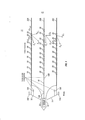
[00012] A figura 1 é um sistema de aquisição e gravação de sinais eletromagnéticos exemplar.[00012] Figure 1 is an exemplary electromagnetic signal acquisition and recording system.
[00013] A figura 2 mostra um gráfico de uma amplitude de sinal normalizada medida na mesma direção com relação ao desvio fonte - sensor usando um transmissor na mesma direção.[00013] Figure 2 shows a graph of a normalized signal amplitude measured in the same direction with respect to source-sensor offset using a transmitter in the same direction.
[00014] A figura 3 mostra um gráfico de amplitudes de sinal normalizadas medidas no sentido transversal para vários desvios fonte - sensor e extensões (spreads) laterais simétricas a partir do centro de um transmissor de direção transversal.[00014] Figure 3 shows a graph of normalized signal amplitudes measured in the transverse direction for various source-sensor deviations and symmetrical lateral extensions (spreads) from the center of a transverse direction transmitter.
[00015] Um sistema de aquisição e gravação de dados eletromagnéticos (EM) marinhos exemplar é mostrado na figura 1. Uma embarcação de pesquisa 10 se movimenta ao longo da superfície de um corpo de água 11, tal como um lago ou o oceano. A embarcação 10 inclui um equipamento no mesmo, mostrado, de modo geral, com a referência numérica 12 e, para fins de conveniência, referido como um "sistema de gravação". O sistema de gravação 12 pode incluir dispositivos (não mostrados separadamente, de modo geral conhecidos na técnica) para a navegação da embarcação 10, no sentido de aplicar corrente elétrica aos transmissores de energia EM (explicados abaixo), e detectar e gravar sinais que representam as tensões impressas através de pares de eletrodos 20 localizados em várias distâncias de desvio dos transmissores de energia EM (explicados abaixo). O sistema de gravação 12 pode incluir ainda um sistema de computador para a interpretação dos sinais detectados e/ou gravados em condutividade elétrica ou de outras imagens baseadas nas formações rochosas abaixo do fundo da água. Em algumas modalidades, o sistema de computador pode determinar os sinais gravados nos componentes de campo elétrico de mesma direção ou na direção transversal.[00015] An exemplary marine electromagnetic (EM) data acquisition and recording system is shown in figure 1. A
[00016] No presente exemplo, o vaso pode rebocar dois transmissores de energia EM. O primeiro transmissor consiste em um cabo 18 rebocado na direção da embarcação 10 tendo sobre o mesmo dois eletrodos espaçados entre si no sentido longitudinal 18A, 18B. Em tempos selecionados, o sistema de gravação 12 passa corrente elétrica entre os eletrodos 18A, 18B. A corrente pode ser de baixa frequência (por exemplo, de cerca de 0,01 a cerca de 1,0 Hz) para um levantamento de energia EM no domínio da frequência, ou pode ser uma corrente contínua tendo um ou mais eventos de comutação, por exemplo, ligar a corrente, desligar a corrente, inverter a polaridade da corrente, ou uma série de eventos de comutação de um padrão particular, tal como uma sequência binária pseudoaleatória (PRBS). O primeiro transmissor emite um campo de energia EM orientado de modo geral na direção de movimento da embarcação, e pode ser referido como o transmissor "na mesma direção". Um segundo transmissor pode consistir de dois eletrodos, mostrados nas referências numéricas 19A e 19B, que podem ser mecanicamente conectados a uma posição externa lateral ao longo de duas das cordas "super largas" 14, 16. As cordas super largas 14, 16 podem conectar, cada uma das mesmas, uma extremidade externa da mesma a uma respectiva paravane ou porta 14A, 16A. Os paravanes 14A, 16A provêem força lateral à medida que a embarcação se movimenta através da água 11 de modo a manter a posição lateral ("spread") de cada qual dentre uma pluralidade de cabos flutuantes com sensor 20A, 20B, 20C com referência à linha de centro da embarcação 10. À medida que a corrente elétrica passa através dos eletrodos 19A e 19B, um campo de energia EM é emitido, que é de uma direção transversal ao movimento da embarcação 10. Esse campo pode ser referido como o campo de energia EM "na direção transversal". Embora o acima mostre transmissores que são da forma de eletrodos espaçados entre si, deve-se entender claramente que resultados similares podem ser obtidos, por exemplo, mediante o uso de bobinas solenóides enroladas 1) de modo que o momento dipolar magnético das mesmas seja equivalente em posição e direção ao momento dipolar elétrico do transmissor de mesma direção e 2) enroladas de modo que o momento dipolar magnético de tal bobina esteja ao longo da mesma direção que o momento dipolar elétrico do transmissor na direção transversal ilustrado.[00016] In the present example, the vessel can tow two EM energy transmitters. The first transmitter consists of a
[00017] Em operação, conforme acima explicado, os transmissores podem ser energizados utilizando várias formas de corrente contínua comutada a fim de realizar um levantamento de energia EM no domínio do tempo. Em um exemplo, ambos os transmissores podem ser operados simultaneamente mediante o uso de uma sequência PRBS diferente para cada transmissor, ou, de preferência, sequências com um coeficiente de correlação cruzada de substancialmente zero. Deste modo, o componente de campo elétrico da mesma direção e o componente de campo elétrico de direção transversal das tensões induzidas em cada par de eletrodos 20 poderão ser identificados.[00017] In operation, as explained above, the transmitters can be energized using various forms of switched direct current in order to perform an EM energy survey in the time domain. In one example, both transmitters can be operated simultaneously using a different PRBS sequence for each transmitter, or, preferably, sequences with a cross-correlation coefficient of substantially zero. In this way, the electric field component of the same direction and the electric field component of the transverse direction of the induced voltages in each pair of
[00018] No presente exemplo, os cabos flutuantes 20A, 20B, 20C podem incluir uma pluralidade de pares de eletrodos espaçados entre si no sentido longitudinal 20. Dispositivos de telemetria, de formatação de dados e de amplificação adequados (nenhum mostrado na figura 1) podem ser incluídos em cada cabo flutuante 20A, 20B, 20C a fim de comunicar sinais de medição de tensão para o sistema de gravação 12. A ilustração da figura 1 é uma vista em planta. Será apreciado pelos versados na técnica que os cabos flutuantes 20A, 20B, 20C são tipicamente rebocados a uma profundidade substancialmente maior na água do que os transmissores.[00018] In the present example, the floating
[00019] A configuração ilustrada tem um transmissor de mesma direção (eletrodos 18A, 18B) e um transmissor de uma direçãotransversal ortogonal (eletrodos 19A, 19B) rebocado próximo a duasportas 14A, 16A seguido pelo cabo flutuante estendido ilustrado(cabos flutuantes 20A, 20B, 20C). Nesse cabo flutuante estendido ilustrado, os pares de eletrodos de mesma direção 20 sobre o cabo flutuante de mesma direção 20B são usados para medir diretamente ocomponente de campo elétrico de mesma direção (Euproj). O componente de campo de energia EM de direção transversal éestimado através da projeção do campo elétrico medido (Eiproj) nos cabos flutuantes descentralizados (20A, 20C conforme ilustrado, porém, de modo geral, qualquer cabo flutuante pode sergeometricamente separado do plano espelhado do transmissor de mesma direção). Esse conceito não requer um eletrodo de referência comum (vide, por exemplo, a Patente U.S. N. 7 602 191, expedida para Davidsson) e, deste modo, simplificaria a configuração do sistema e aperfeiçoaria a robustez do sistema como um todo.[00019] The illustrated configuration has a transmitter of the same direction (
[00020] Equações exemplares para a extração dos componentes de direção transversal são como se seguem:
[00021] A título de exemplo, para umaseparação de eletrodo de transmissor de mesma direção de 400 m, o componente normalizado E||proj medido com um par de eletrodos de mesma direção de 200 m é ilustrado na figura 2. Com um cabo flutuante estendido de 2 km (1 km de distância lateral sobre ambos oslados da linha de centro), o eletrodo Eiproj medido tem uma amplitude que é, na pior das hipóteses, 13dB mais baixa sobre uma faixa de desvio fonte - sensor de 1 a 6km que o eletrodo Epoj. O gráfico da figura 3 ilustra uma sensibilidade de sinal de direção transversal exemplar com relação às várias separações de extensão (duplica a separação lateral de um único cabo flutuante a partir da linha de centro do transmissor de direção transversal). Esse exemplo indica que pode ser possível otimizar o cabo flutuante estendido de modo a obter uma sensibilidade máxima para um desvio específico. Conforme ilustrado, uma extensão de 500 metros é mostrada na curva 32, uma extensão de 1000 metros é mostrada na curva 34, uma extensão de 1500 metros é mostrada na curva 36, e uma extensão de 2 km é mostrada na curva 38.[00021] As an example, for a 400 m same direction transmitter electrode separation, the normalized component E||proj measured with a pair of 200 m same direction electrodes is illustrated in figure 2. With a floating cable Extended 2 km (1 km lateral distance over both sides of the centerline), the measured Eiproj electrode has an amplitude that is, at worst, 13dB lower over a source deviation range - 1 to 6 km sensor than the Epoj electrode. The graph of Figure 3 illustrates an exemplary cross-direction signal sensitivity with respect to the various extension separations (doubles the lateral separation of a single floating cable from the centerline of the cross-direction transmitter). This example indicates that it may be possible to optimize the extended floating cable to obtain maximum sensitivity for a specific deviation. As illustrated, a 500 meter span is shown on
[00022] Um método de levantamento de energia EM de acordo com a presente invenção pode oferecer resultados de interpretação aperfeiçoados e ao mesmo tempo manter a eficiência operacional do levantamento.[00022] An EM energy survey method according to the present invention can offer improved interpretation results while maintaining the operational efficiency of the survey.
[00023] Embora a presente invenção tenha sido descrita com respeito a um número limitado de modalidades, os versados na técnica, tendo o benefício dessa apresentação, irão apreciar que outras modalidades podem ser concebidas, sem se afastar do âmbito de aplicação da presente invenção conforme divulgada nesse documento. Por conseguinte, o âmbito de aplicação da presente invenção deve ser limitado tão-somente pelas reivindicações em anexo.[00023] Although the present invention has been described with respect to a limited number of embodiments, those skilled in the art, having the benefit of this disclosure, will appreciate that other embodiments can be devised without departing from the scope of the present invention as per disclosed in this document. Therefore, the scope of application of the present invention is to be limited only by the appended claims.
Claims (11)
Applications Claiming Priority (2)
| Application Number | Priority Date | Filing Date | Title |
|---|---|---|---|
| US12/799,941 US8896314B2 (en) | 2010-05-05 | 2010-05-05 | Multiple component electromagnetic survey signal acquisition method |
| US12/799,941 | 2010-05-05 |
Publications (2)
| Publication Number | Publication Date |
|---|---|
| BRPI1102263A2 BRPI1102263A2 (en) | 2012-10-16 |
| BRPI1102263B1 true BRPI1102263B1 (en) | 2021-06-08 |
Family
ID=44203166
Family Applications (1)
| Application Number | Title | Priority Date | Filing Date |
|---|---|---|---|
| BRPI1102263-9A BRPI1102263B1 (en) | 2010-05-05 | 2011-05-04 | method and system for marine electromagnetic survey |
Country Status (5)
| Country | Link |
|---|---|
| US (1) | US8896314B2 (en) |
| AU (1) | AU2011201611B2 (en) |
| BR (1) | BRPI1102263B1 (en) |
| GB (1) | GB2480149B (en) |
| NO (2) | NO337761B1 (en) |
Families Citing this family (10)
| Publication number | Priority date | Publication date | Assignee | Title |
|---|---|---|---|---|
| US9110195B2 (en) * | 2011-04-14 | 2015-08-18 | Wen J. Whan | Electromagnetic and its combined surveying apparatus and method |
| US8710845B2 (en) * | 2011-09-19 | 2014-04-29 | Pgs Geophysical As | Electromagnetic sensor cable and electrical configuration therefor |
| US8816690B2 (en) | 2011-11-21 | 2014-08-26 | Pgs Geophysical As | Electromagnetic sensor cable and electrical configuration therefor |
| US8587316B2 (en) | 2011-12-08 | 2013-11-19 | Pgs Geophysical As | Noise reduction systems and methods for a geophysical survey cable |
| US8928324B2 (en) * | 2011-12-27 | 2015-01-06 | Pgs Geophysical As | In-line and broadside marine electromagnetic surveying |
| US8922214B2 (en) | 2011-12-27 | 2014-12-30 | Pgs Geophysical As | Electromagnetic geophysical survey systems and methods employing electric potential mapping |
| US8736269B2 (en) | 2011-12-27 | 2014-05-27 | Pgs Geophysical As | Electromagnetic geophysical survey systems and methods employing electric potential mapping |
| US9239401B2 (en) * | 2012-03-01 | 2016-01-19 | Pgs Geophysical As | Stationary source for marine electromagnetic surveying |
| US10795043B2 (en) * | 2017-02-28 | 2020-10-06 | Pgs Geophysical As | Towable electromagnetic source equipment |
| US10877177B2 (en) * | 2017-12-18 | 2020-12-29 | Pgs Geophysical As | Obtaining long-period magnetotelluric marine survey data using a towed streamer system |
Family Cites Families (8)
| Publication number | Priority date | Publication date | Assignee | Title |
|---|---|---|---|---|
| NO326506B1 (en) * | 2003-07-10 | 2008-12-15 | Norsk Hydro As | A marine geophysical collection system with a cable with seismic sources and receivers and electromagnetic sources and receivers |
| US7340348B2 (en) * | 2006-06-15 | 2008-03-04 | Kjt Enterprises, Inc. | Method for acquiring and interpreting seismoelectric and electroseismic data |
| GB2441786A (en) | 2006-09-15 | 2008-03-19 | Electromagnetic Geoservices As | Combined electromagnetic and seismic surveying |
| US7659724B2 (en) * | 2007-03-29 | 2010-02-09 | Westerngeco L.L.C. | Surveying method using an arrangement of plural signal sources |
| US7602191B2 (en) | 2007-06-29 | 2009-10-13 | Pgs Geophysical As | Cable-type electromagnetic receiver system for subsurface exploration |
| US7446535B1 (en) | 2007-09-21 | 2008-11-04 | Pgs Geopysical As | Electrode structure and streamer made therewith for marine electromagnetic surveying |
| US7834632B2 (en) * | 2007-12-03 | 2010-11-16 | Pgs Geophysical As | Receiver streamer system and method for marine electromagnetic surveying |
| US7974151B2 (en) | 2008-09-17 | 2011-07-05 | Westerngeco L.L.C. | Cetacean protection system |
-
2010
- 2010-05-05 US US12/799,941 patent/US8896314B2/en active Active
-
2011
- 2011-04-08 AU AU2011201611A patent/AU2011201611B2/en not_active Ceased
- 2011-05-02 NO NO20110652A patent/NO337761B1/en not_active IP Right Cessation
- 2011-05-04 BR BRPI1102263-9A patent/BRPI1102263B1/en not_active IP Right Cessation
- 2011-05-05 GB GB1107448.1A patent/GB2480149B/en not_active Expired - Fee Related
-
2016
- 2016-03-02 NO NO20160354A patent/NO338987B1/en not_active IP Right Cessation
Also Published As
| Publication number | Publication date |
|---|---|
| GB2480149A (en) | 2011-11-09 |
| GB2480149B (en) | 2014-07-09 |
| NO338987B1 (en) | 2016-11-07 |
| BRPI1102263A2 (en) | 2012-10-16 |
| AU2011201611A1 (en) | 2011-11-24 |
| NO20110652A1 (en) | 2011-11-07 |
| US20110273179A1 (en) | 2011-11-10 |
| US8896314B2 (en) | 2014-11-25 |
| GB201107448D0 (en) | 2011-06-15 |
| NO20160354A1 (en) | 2011-11-07 |
| AU2011201611B2 (en) | 2014-09-11 |
| NO337761B1 (en) | 2016-06-20 |
Similar Documents
| Publication | Publication Date | Title |
|---|---|---|
| BRPI1102263B1 (en) | method and system for marine electromagnetic survey | |
| US7834632B2 (en) | Receiver streamer system and method for marine electromagnetic surveying | |
| CA2741011C (en) | Method for determining electromagnetic survey sensor orientation | |
| US8810248B2 (en) | Method of testing electric field recording of a marine electromagnetic sensor cable | |
| AU2011201226B2 (en) | Method for 2D and 3D electromagnetic field measurements using a towed marine electromagnetic survey system | |
| BRPI0816462B1 (en) | ELECTROMAGNETIC SURVEY DETECTION DEVICE, ELECTROMAGNETIC SURVEY SYSTEM, METHOD FOR DETECTING AN ELECTROMAGNETIC FIELD AND METHOD FOR ELECTROMAGNETIC SURVEY OF EARTH SUBSURFACE FORMATIONS | |
| BRPI1101615A2 (en) | switchable front end measuring unit for marine towed electromagnetic sounding cables | |
| BRPI0701248B1 (en) | detector for marine electromagnetic inspection system and method for marine electromagnetic inspection | |
| BRPI0915950B1 (en) | METHOD TO REDUCE THE MOVEMENT EFFECT ON ELECTROMAGNETIC SIGNS DETECTED DURING THE MOVEMENT OF AN ELECTROMAGNETIC RECEIVER | |
| BRPI0915113B1 (en) | METHOD FOR ELECTROMAGNETIC EXPLORATION OF SUBSURFACE FORMATIONS BELOW A MASS OF WATER AND METHOD FOR DETERMINING A FORMATION RESPONSE OF A DETECTED ELECTROMAGNETIC SIGNAL | |
| BR102012033262A2 (en) | RADIAL AND AZIMUTAL MARINE ELECTROMAGNETIC SURVEY | |
| US7795873B2 (en) | Method for attenuating air wave response in marine electromagnetic surveying | |
| BRPI1000323A2 (en) | small displacement transient electromagnetic geophysical lifting | |
| EP2149058A1 (en) | Multi-component marine electromagnetic signal acquisition cable, system and method | |
| BRPI1000912A2 (en) | method for the determination of resistivity anisotropy from earth electromagnetic responses |
Legal Events
| Date | Code | Title | Description |
|---|---|---|---|
| B03A | Publication of a patent application or of a certificate of addition of invention [chapter 3.1 patent gazette] | ||
| B06F | Objections, documents and/or translations needed after an examination request according [chapter 6.6 patent gazette] | ||
| B06U | Preliminary requirement: requests with searches performed by other patent offices: procedure suspended [chapter 6.21 patent gazette] | ||
| B06A | Patent application procedure suspended [chapter 6.1 patent gazette] | ||
| B09A | Decision: intention to grant [chapter 9.1 patent gazette] | ||
| B16A | Patent or certificate of addition of invention granted [chapter 16.1 patent gazette] |
Free format text: PRAZO DE VALIDADE: 20 (VINTE) ANOS CONTADOS A PARTIR DE 04/05/2011, OBSERVADAS AS CONDICOES LEGAIS. PATENTE CONCEDIDA CONFORME ADI 5.529/DF |
|
| B21F | Lapse acc. art. 78, item iv - on non-payment of the annual fees in time |
Free format text: REFERENTE A 13A ANUIDADE. |