BRPI1014565B1 - method for designing a communication cable, and, communication cable - Google Patents
method for designing a communication cable, and, communication cable Download PDFInfo
- Publication number
- BRPI1014565B1 BRPI1014565B1 BRPI1014565-6A BRPI1014565A BRPI1014565B1 BR PI1014565 B1 BRPI1014565 B1 BR PI1014565B1 BR PI1014565 A BRPI1014565 A BR PI1014565A BR PI1014565 B1 BRPI1014565 B1 BR PI1014565B1
- Authority
- BR
- Brazil
- Prior art keywords
- cable
- matrix
- conductive segments
- layer
- twisted
- Prior art date
Links
Images


Classifications
-
- H—ELECTRICITY
- H01—ELECTRIC ELEMENTS
- H01B—CABLES; CONDUCTORS; INSULATORS; SELECTION OF MATERIALS FOR THEIR CONDUCTIVE, INSULATING OR DIELECTRIC PROPERTIES
- H01B11/00—Communication cables or conductors
- H01B11/02—Cables with twisted pairs or quads
- H01B11/06—Cables with twisted pairs or quads with means for reducing effects of electromagnetic or electrostatic disturbances, e.g. screens
- H01B11/08—Screens specially adapted for reducing cross-talk
- H01B11/085—Screens specially adapted for reducing cross-talk composed of longitudinal tape conductors
-
- H—ELECTRICITY
- H01—ELECTRIC ELEMENTS
- H01B—CABLES; CONDUCTORS; INSULATORS; SELECTION OF MATERIALS FOR THEIR CONDUCTIVE, INSULATING OR DIELECTRIC PROPERTIES
- H01B11/00—Communication cables or conductors
- H01B11/02—Cables with twisted pairs or quads
-
- H—ELECTRICITY
- H01—ELECTRIC ELEMENTS
- H01B—CABLES; CONDUCTORS; INSULATORS; SELECTION OF MATERIALS FOR THEIR CONDUCTIVE, INSULATING OR DIELECTRIC PROPERTIES
- H01B11/00—Communication cables or conductors
- H01B11/02—Cables with twisted pairs or quads
- H01B11/06—Cables with twisted pairs or quads with means for reducing effects of electromagnetic or electrostatic disturbances, e.g. screens
- H01B11/10—Screens specially adapted for reducing interference from external sources
- H01B11/1008—Features relating to screening tape per se
-
- H—ELECTRICITY
- H01—ELECTRIC ELEMENTS
- H01R—ELECTRICALLY-CONDUCTIVE CONNECTIONS; STRUCTURAL ASSOCIATIONS OF A PLURALITY OF MUTUALLY-INSULATED ELECTRICAL CONNECTING ELEMENTS; COUPLING DEVICES; CURRENT COLLECTORS
- H01R13/00—Details of coupling devices of the kinds covered by groups H01R12/70 or H01R24/00 - H01R33/00
- H01R13/646—Details of coupling devices of the kinds covered by groups H01R12/70 or H01R24/00 - H01R33/00 specially adapted for high-frequency, e.g. structures providing an impedance match or phase match
- H01R13/6461—Means for preventing cross-talk
- H01R13/6463—Means for preventing cross-talk using twisted pairs of wires
-
- H—ELECTRICITY
- H04—ELECTRIC COMMUNICATION TECHNIQUE
- H04M—TELEPHONIC COMMUNICATION
- H04M11/00—Telephonic communication systems specially adapted for combination with other electrical systems
- H04M11/02—Telephonic communication systems specially adapted for combination with other electrical systems with bell or annunciator systems
- H04M11/025—Door telephones
Abstract
CABO, E, MÉTODO PARA DIMENSIONAR UM COMPRIMENTO DE UM SEGMENTO CONDUTIVO. É provido um cabo de comunicação com uma pluralidade de 5 pares torcidos de condutores e uma fita matriz tendo segmentos condutivos separados por fendas. As dimensões dos segmentos condutivos são selecionadas para reduzir o acoplamento indesejável de sinais entre cabos adjacentes. Uma camada isolante pode ser provida entre os pares torcidos de condutores e a fita matriz. Em algumas formas de realização, a camada isolante é uma película em relevo ou perfurada. O uso de uma película em relevo ou perfurada diminui a constante dielétrica da camada isolante.CABLE, AND, METHOD FOR SIZING A LENGTH OF A CONDUCTIVE SEGMENT. A communication cable is provided with a plurality of 5 twisted pairs of conductors and a matrix tape having conductive segments separated by slits. The dimensions of the conductive segments are selected to reduce the undesirable coupling of signals between adjacent cables. An insulating layer can be provided between the twisted pairs of conductors and the matrix tape. In some embodiments, the insulating layer is an embossed or perforated film. The use of an embossed or perforated film decreases the dielectric constant of the insulating layer.
Description
[0001] A presente invenção refere-se a cabos de comunicação e, mais particularmente, a métodos e aparelho para aprimorar as características elétricas de tais cabos.[0001] The present invention relates to communication cables and, more particularly, to methods and apparatus for improving the electrical characteristics of such cables.
[0002] À medida que as redes tornam-se mais complexas e têm necessidade de cabeamento de banda-larga mais elevado, a capacidade de satisfazer especificações elétricas prescritas, tais como aquelas relacionadas com diafonia de cabo-para-cabo (“diafonia estranha”), diafonia próxima (PRÓXIMA) entre pares de fio dentro de um cabo e atenuação de sinal de dados, torna-se crescentemente importante prover um sistema de comunicação robusto e confiável.[0002] As networks become more complex and need higher broadband cabling, the ability to meet prescribed electrical specifications, such as those related to cable-to-cable crosstalk ("strange crosstalk" ), close crosstalk (NEXT) between wire pairs within a cable and data signal attenuation, it becomes increasingly important to provide a robust and reliable communication system.
[0003] Muitos vendedores de cabos de comunicação utilizam fendas ou espaçamento de ar entre cabos para atender às exigências de desempenho. Outra solução envolve o uso de uma fita matriz enrolada em torno dos pares de fio de um cabo de par torcido não blindado (UTP). O Pedido de Patente U.S. No. 12/399.331, intitulado “Communication Cable with Improved Crosstalk Attenuation”; e também a Publicação Internacional No. WO 2008/157175, intitulada “Communication Channels with Crosstalk-Mitigating Material”, cedidos a Panduit Corp, descreve uma tal solução e são por este meio incorporados por referência aqui em sua totalidade. A solução de fita matriz tem tido sucesso na atenuação da diafonia; entretanto, a melhoria das características elétricas adicionais, tais como reduzida atenuação de sinal de dados, ressonância de diafonia estranha controlada, compatibilidade eletro- magnética (EMC) e/ou evitação de acoplamento de modo diferencial coerente entre cabos, é desejável.[0003] Many communication cable vendors use slots or air spacing between cables to meet performance requirements. Another solution involves the use of a matrix ribbon wrapped around the wire pairs of an unshielded twisted pair (UTP) cable. U.S. Patent Application No. 12 / 399,331, entitled "Communication Cable with Improved Crosstalk Attenuation"; and also International Publication No. WO 2008/157175, entitled “Communication Channels with Crosstalk-Mitigating Material”, assigned to Panduit Corp, describes such a solution and is hereby incorporated by reference here in its entirety. The matrix tape solution has been successful in attenuating crosstalk; however, the improvement of additional electrical characteristics, such as reduced data signal attenuation, controlled strange crosstalk resonance, electromagnetic compatibility (EMC) and / or avoiding coherently differential coupling between cables, is desirable.
[0004] Para fins de facilitar um entendimento da invenção, os desenhos acompanhantes e descrição ilustram suas formas de realização, de cuja invenção a estrutura, construção e operação e muitas vantagens relacionadas podem ser prontamente entendidas e apreciadas.[0004] For the purpose of facilitating an understanding of the invention, the accompanying drawings and description illustrate its embodiments, the invention of which the structure, construction and operation and many related advantages can be readily understood and appreciated.
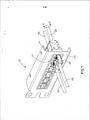
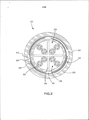
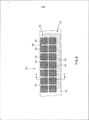
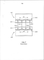
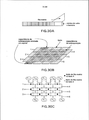
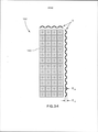
[0005] A Fig. 1 é uma vista esquemática de uma forma de realização de um sistema de comunicação incluindo múltiplos cabos de comunicação, de acordo com a presente invenção; A Fig. 2 é uma vista em seção transversal de um dos cabos de comunicação, tomada ao longo da linha de seção 2 - 2 da Fig. 1; A Fig. 3 é uma vista em planta fragmentar de uma forma de realização de uma fita de matriz de acordo com a presente invenção e usada nos cabos das Figs. 1 e 2; A Fig. 4 é uma vista em seção transversal da fita matriz da Fig. 3, tomada ao longo da seção 4 - 4 da Fig. 3; A Fig. 5 é uma vista em seção transversal longitudinal de modelagem de capacidade parasítica de dois cabos da arte anterior; A Fig. 6 é uma vista em seção transversal longitudinal da modelagem de capacidade parasítica de dois cabos de acordo com uma forma de realização da presente invenção; A Fig. 7 é uma vista em seção transversal longitudinal de uma modelagem indutiva parasítica de dois cabos da arte anterior; A Fig. 8 é uma vista em seção transversal longitudinal de uma modelagem indutiva parasítica de dois cabos de acordo com uma forma de realização da presente invenção; A Fig. 9 é uma vista em perspectiva de uma forma de realização do cabo da Fig. 1, ilustrando a natureza espiralante da instalação da fita matriz dentro do cabo; A Fig. 10 é uma vista em planta fragmentar de outra forma de realização de uma fita matriz de acordo com a presente invenção; A Fig. 11 é uma vista em seção transversal da fita matriz da Fig. 10, tomada ao longo da linha 11 - 11 da Fig. 10; A Fig. 12 é uma vista em seção transversal de um cabo 10 Gb/s Ethernet U/UTP Cat 6a, em que uma fita matriz de 2-tijolos, de duplo lado é empregada de acordo com uma forma de realização da presente invenção; A Fig. 13 é uma vista em seção transversal de um cabo 10 Gb/s Ethernet U/UTP Cat 6a, em que uma fita matriz de 3-tijolos, duplo lado é empregada de acordo com uma forma de realização da presente invenção; A Fig. 14 é uma fita matriz de 3-tijolos, duplo lado, acordo com uma forma de realização da presente invenção; A Fig. 15 é uma vista em seção transversal de um cabo 10 Gb/s Ethernet U/UTP Cat 6a, em que uma fita matriz de 3-tijolos, de duplo lado é empregada acordo com uma forma de realização da presente invenção; A Fig. 16 é uma vista em seção transversal de um cabo 10 Gb/s Ethernet U/UTP Cat 6a, em que uma fita matriz de 4-tijolos, duplo lado é empregada acordo com uma forma de realização da presente invenção; A Fig. 17A-C são diagramas conceituais ilustrando perspectivas equivalentes de formatos metálicos (isto é, tijolos ou segmentos condutivos) de uma fita matriz em relação a pares de fio torcidos sobrepostos pelos formatos metálicos; A Fig. 18 é um gráfico mostrando a especificação NEXT estranha de soma de potência (PSANEXT) e nível de resposta de cabo para uma construção de cabo empregando uma fita matriz tendo uma periodicidade de formato metálico específico, de modo que exista um elevado nível de acoplamento de modo diferencial próximo de 440 MHz entre dois cabos similarmente construídos; As Figuras 19A-D são diagramas conceituais ilustrando mecanismos de acoplamento de diafonia estranha de modo diferencial e modo comum para cabos U/UTP com e sem fita matriz; As Figuras 20A-D são diagramas conceituais ilustrando mecanismos de acoplamento de diafonia estranha de modo diferencial e modo comum para cabos U/UTP com e sem fita matriz; As Figuras 20A-D são diagramas conceituais ilustrando mecanismos de acoplamento de diafonia estranha modo diferencial e modo comum para cabos U/UTP com fita matriz; A Fig. 21A é um diagrama conceitual ilustrando extensão de coerência em função de periodicidade de formato metálico e periodicidade de par de fio torcido; A Fig. 21B é um digrama conceitual ilustrando acoplamento capacitivo entre tijolos em dois cabos vizinhos; As Figs. 22A-B são diagramas conceituais ilustrando a carga relativa em um tijolo quando um par torcido torce sob o tijolo, mostrados como seções transversais sucessivas progredindo longitudinalmente ao longo de um cabo; As Figs. 23A-D são diagramas de vista lateral conceitual ilustrando a carga relativa em um tijolo, quando o comprimento do tijolo muda com respeito a camada de par torcido; A Fig. 24A é um gráfico ilustrando as frequências em que o acoplamento de modo diferencial coerente ocorre para diferentes múltiplos do deslocamento entre a periodicidade de fita matriz e a camada de par torcido; As Figs. 24B-D são digramas conceituais ilustrando dependência de comprimento de coerência em um deslocamento entre periodicidade de fita matriz e camada de par torcido; A Fig. 25A é um diagrama listando comprimentos de camada torcida “manter fora” para uma dada periodicidade de formatos metálicos; A Fig. 25B é um diagrama de um conjunto de pares torcidos exemplo que se conforma com as diretrizes de projeto mostradas na Fig. 25A; As Figs. 26A-B são diagramas esquemáticos ilustrando variação posicional sob um tijolo para um padrão de tijolo retangular e um padrão de tijolo paralelogramo não-retangular; A Fig. 27 é um diagrama esquemático ilustrando um padrão de tijolos paralelogramo alinhados com os respectivos pares; A Fig. 28A-C são diagramas conceituais ilustrando variação de carga que pode ocorrer se a mudança de posição de um elemento condutivo, relativa à camada de par de fio, for da ordem de mais ou menos 10% do comprimento de camada de par de fio; A Fig. 29A é um diagrama em perspectiva de uma fita matriz de tijolo-retangular enrolada em torno de um núcleo e barreira de cabo; A Fig. 29B é um diagrama conceitual ilustrando capacitância sobreposta enrolada-espiral e capacitância sobreposta para uma fita matriz de tijolo retangular enrolada em torno de um núcleo e barreira de cabo; A Fig. 29C é um diagrama de circuito equivalente da configuração da Fig. 29B; A Fig. 30A é um diagrama em perspectiva de uma fita matriz de tijolo-retangular enrolada em torno de um núcleo e barreira de cabo; A Fig. 30B é um diagrama conceitual ilustrando capacitância sobreposta enrolada-espiral e capacitância sobreposta para uma fita matriz de tijolo-paralelogramo não regular enrolada em torno de um núcleo e barreira de cabo; A Fig. 30C é um diagrama de circuito equivalente da configuração da Fig. 30B; A Fig. 31 é um diagrama descrevendo os espectros de atenuação de um cabo U/UTP com e sem fita matriz em relação à especificação T1A568 para atenuação, respectivamente; As Figs. 32A-B são diagramas conceituais ilustrando campos magnético circundando cabos U/UTP sem e com fita matriz, respectivamente; A Fig. 33 é uma vista em seção transversal de um cabo incorporando uma película em relevo como uma camada isolante; A Fig. 34 é uma vista em planta de uma película em relevo; As Figs. 35(a) e (b) mostram vistas laterais da construção de uma camada de barreira perfurada; A Fig. 36 mostra um dispositivo para manufaturar uma camada de barreira perfurada; A Fig. 37 é uma vista em perspectiva de uma camada de barreira perfurada; A Fig. 38 é uma vista em perspectiva de uma camada de barreira perfurada; e A Fig. 39 é uma vista em seção transversal de um cabo tendo uma camada de barreira perfurada.[0005] Fig. 1 is a schematic view of an embodiment of a communication system including multiple communication cables, in accordance with the present invention; Fig. 2 is a cross-sectional view of one of the communication cables, taken along section line 2 - 2 of Fig. 1; Fig. 3 is a fragmentary plan view of an embodiment of a matrix tape according to the present invention and used in the cables of Figs. 1 and 2; Fig. 4 is a cross-sectional view of the matrix tape of Fig. 3, taken along section 4 - 4 of Fig. 3; Fig. 5 is a longitudinal cross-sectional view of modeling the parasitic capacity of two prior art cables; Fig. 6 is a longitudinal cross-sectional view of the modeling of parasitic capacity of two cables according to an embodiment of the present invention; Fig. 7 is a longitudinal cross-sectional view of a parasitic inductive modeling of two prior art cables; Fig. 8 is a longitudinal cross-sectional view of a parasitic inductive modeling of two cables according to an embodiment of the present invention; Fig. 9 is a perspective view of an embodiment of the cable of Fig. 1, illustrating the spiraling nature of the installation of the matrix tape within the cable; Fig. 10 is a fragmentary plan view of another embodiment of a matrix tape according to the present invention; Fig. 11 is a cross-sectional view of the matrix ribbon of Fig. 10, taken along line 11 - 11 of Fig. 10; Fig. 12 is a cross-sectional view of a 10 Gb / s Ethernet U / UTP Cat 6a cable, in which a double-sided 2-brick matrix tape is employed in accordance with an embodiment of the present invention; Fig. 13 is a cross-sectional view of a 10 Gb / s Ethernet U / UTP Cat 6a cable, in which a double-sided 3-brick matrix ribbon is employed in accordance with an embodiment of the present invention; Fig. 14 is a double-sided 3-brick matrix tape according to an embodiment of the present invention; Fig. 15 is a cross-sectional view of a 10 Gb / s Ethernet U / UTP Cat 6a cable, in which a double-sided 3-brick matrix ribbon is employed in accordance with an embodiment of the present invention; Fig. 16 is a cross-sectional view of a 10 Gb / s Ethernet U / UTP Cat 6a cable, in which a double-sided 4-brick matrix tape is employed in accordance with an embodiment of the present invention; Fig. 17A-C are conceptual diagrams illustrating equivalent perspectives of metallic shapes (i.e., bricks or conductive segments) of a matrix ribbon in relation to twisted wire pairs overlapped by the metallic shapes; Fig. 18 is a graph showing the strange NEXT specification of power sum (PSANEXT) and cable response level for a cable construction employing a matrix tape having a specific metallic shape periodicity, so that there is a high level of differential mode coupling near 440 MHz between two similarly constructed cables; Figures 19A-D are conceptual diagrams illustrating differential crosstalk coupling mechanisms in a differential and common mode for U / UTP cables with and without matrix tape; Figures 20A-D are conceptual diagrams illustrating differential crosstalk coupling mechanisms in a differential and common mode for U / UTP cables with and without matrix tape; Figures 20A-D are conceptual diagrams illustrating differential crosstalk coupling mechanisms, differential mode and common mode for U / UTP cables with matrix tape; Fig. 21A is a conceptual diagram illustrating the extent of coherence as a function of metallic shape periodicity and twisted wire pair periodicity; Fig. 21B is a conceptual diagram illustrating capacitive coupling between bricks on two neighboring cables; Figs. 22A-B are conceptual diagrams illustrating the relative load on a brick when a twisted pair twists under the brick, shown as successive cross sections progressing longitudinally along a cable; Figs. 23A-D are conceptual side view diagrams illustrating the relative load on a brick, when the length of the brick changes with respect to the twisted pair layer; Fig. 24A is a graph illustrating the frequencies at which coherent differential mode coupling occurs for different multiples of the displacement between the matrix tape periodicity and the twisted pair layer; Figs. 24B-D are conceptual diagrams illustrating coherence length dependence on a shift between matrix tape periodicity and twisted pair layer; Fig. 25A is a diagram listing twisted layer lengths “keep out” for a given periodicity of metallic shapes; Fig. 25B is a diagram of a set of example twisted pairs that conforms to the design guidelines shown in Fig. 25A; Figs. 26A-B are schematic diagrams illustrating positional variation under a brick for a rectangular brick pattern and a non-rectangular parallelogram brick pattern; Fig. 27 is a schematic diagram illustrating a pattern of parallelogram bricks aligned with the respective pairs; Fig. 28A-C are conceptual diagrams illustrating load variation that can occur if the change in position of a conductive element, relative to the wire pair layer, is of the order of about 10% of the length of the pair wire layer. thread; Fig. 29A is a perspective diagram of a brick-rectangular matrix ribbon wrapped around a core and cable barrier; Fig. 29B is a conceptual diagram illustrating spiral-wound overlapping capacitance and overlapping capacitance for a rectangular brick matrix ribbon wrapped around a core and cable barrier; Fig. 29C is an equivalent circuit diagram of the configuration in Fig. 29B; Fig. 30A is a perspective diagram of a rectangular brick matrix tape wrapped around a core and cable barrier; Fig. 30B is a conceptual diagram illustrating spiral-wound overlapping capacitance and overlapping capacitance for a non-regular brick-parallelogram matrix ribbon wrapped around a core and cable barrier; Fig. 30C is an equivalent circuit diagram of the configuration in Fig. 30B; Fig. 31 is a diagram describing the attenuation spectra of a U / UTP cable with and without matrix tape in relation to the T1A568 specification for attenuation, respectively; Figs. 32A-B are conceptual diagrams illustrating magnetic fields surrounding U / UTP cables without and with matrix tape, respectively; Fig. 33 is a cross-sectional view of a cable incorporating an embossed film as an insulating layer; Fig. 34 is a plan view of an embossed film; Figs. 35 (a) and (b) show side views of the construction of a perforated barrier layer; Fig. 36 shows a device for manufacturing a perforated barrier layer; Fig. 37 is a perspective view of a perforated barrier layer; Fig. 38 is a perspective view of a perforated barrier layer; and Fig. 39 is a cross-sectional view of a cable having a perforated barrier layer.
[0006] Com referência agora aos desenhos e, mais particularmente, à Fig. 1, é mostrado um sistema de comunicação 20, que inclui pelo menos um cabo de comunicação 22, 23 conectado ao equipamento 24. O Equipamento 24 é ilustrado como um painel de embutimento na Fig. 1, porém o equipamento pode ser equipamento passivo ou equipamento ativo. Exemplos de equipamento passivo podem ser, mas não são limitados a painéis de embutimento modular, painéis de embutimento de perfuração descendente, painéis de embutimento acopladores, camisas de parede etc. Exemplos de equipamento ativo podem ser mas não limitados a comutadores Ethernet, roteadores, servidores, sistemas de controle de camada física e equipamento energização-Ethernet, como podem ser encontrados em centros de dados/salas de telecomunicações; dispositivos de segurança (câmeras e outros sensores etc.) e equipamento de acesso a porta; e telefones, computadores, máquinas de fax, impressoras e outros periféricos que podem ser encontrados em áreas de estação de trabalho. Os sistemas de comunicação 20 podem ainda incluir cabines, prateleiras, sistemas de controle de cabo e de roteamento aéreo, por exemplo.[0006] Referring now to the drawings and, more particularly, to Fig. 1, a
[0007] O cabo de comunicação 22, 23 pode ser na forma de um cabo horizontal de par torcido não-blindado (UTP) 22 e/ou como um cabo embutido 23 e, mais particularmente, um cabo Categoria 6A, que possa operar a 500 MHz e 10 Gb/s, como é mostrado mais particularmente na Fig. 2 e que é descrito mais detalhadamente abaixo. Entretanto, a presente invenção pode ser aplicada a e/ou implementada em uma variedade de cabos de comunicação, como já foi descrito, bem como outros tipos de cabos. Os cabos 22, 23 podem ser terminados diretamente dentro do equipamento 24 ou, alternativamente, pode ser terminado em uma variedade de plugues 25 ou módulos de tomada 27 (tais como tipo RJ45), cassetes de modulo de tomada, conectores Infiniband, RJ21 e muitos outros tipos de conectores ou suas combinações. Além disso, os cabos 22, 23 podem ser processados em tubos, ou feixes, de cabos e, adicionalmente, podem ser processados em tubos predeterminados.[0007]
[0008] O cabo de comunicação 22, 23 pode ser usado em uma variedade de aplicações de cabeamento estruturado, incluindo cordas embutidas, cordas zonais, cabeamento principal e cabeamento horizontal, embora a presente invenção não seja limitada a tais aplicações. Em geral, a presente invenção pode ser usada em telecomunicações militares, industriais, residenciais, computador, comunicações de dados e outras aplicações de cabeamento.[0008]
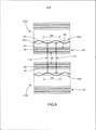
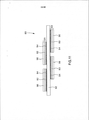
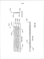
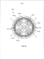
[0009] Com referência mais particularmente à Fig. 2, nela é mostrada uma seção transversal transversa do cabo 22, 23. O cabo 22, 23 inclui um núcleo de cabo 29 de quatro pares de fio condutivos torcidos 26, que são tipicamente separados com uma membrana-cruzada 28. Uma camada isolante interna 30 (p.ex., uma fita isolante plástica ou uma camada isolante extrusada, por exemplo, um material camisa isolante interna com a espessura de 10 mil) circunda os pares de fio condutivos 26 e a membrana-transversal 28. Um enrolamento da fita matriz 32 (também conhecido como “fita barreira”) circunda a camada isolante interna 30. A fita matriz 32 pode ser helicoidalmente enrolada em torno da camada isolante 30. O cabo 22, 23 também pode incluir uma camisa isolante externa 33. A fita matriz 32 é mostrada em uma versão condensada para simplicidade na Fig. 2, ilustrando somente um substrato isolante 42 e segmentos condutivos 34 e 38.[0009] Referring more particularly to Fig. 2, a cross-section of the
[00010] Com referência também às Figs. 3 e 4 e como é discutido em mais detalhes abaixo, a fita matriz 32 inclui uma primeira camada de barreira 35 (mostrada na Fig. 2 como uma camada de barreira interna) compreendendo segmentos condutivos 34 separados por fendas 36; uma segunda camada de barreira 37 (mostrada na Fig. 2 como uma camada de barreira externa) compreendendo segmentos condutivos 38 separados por fendas 40 no material condutivo de segmentos 38; e um substrato isolante 42 separando segmentos condutivos 34 e fendas 36 da primeira camada condutiva de segmentos condutivos 38 e fendas 40 da segunda camada condutiva. As primeira e segunda camadas barreira e, mais particularmente, os segmentos condutivos 34 e segmentos condutivos 38, são escalonados dentro do cabo, de modo que as fendas 40 da camada de barreira externa alinham-se com os segmentos condutivos 34 da camada condutiva interna. A fita matriz 32 pode ser helicoidal ou espiralmente enrolada em torno da camada isolante interna 30. Alternativamente, a fita matriz pode ser aplicada em torno da camada isolante em uma maneira não-helicoidal (p. ex., estilo cigarro ou longitudinal).[00010] With reference also to Figs. 3 and 4 and as is discussed in more detail below,
[00011] A camisa isolante externa 33 pode ter a espessura de 15 - 16 mil (entretanto, outras espessuras são possíveis). O diâmetro total do cabo 22 pode ser de 300 mils, por exemplo; entretanto, outras espessuras são possíveis, tais como na faixa de 270 - 305 mils ou outras espessuras.[00011] The
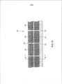
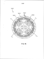
[00012] A Fig. 3 é uma vista em planta da fita matriz 32 ilustrando os segmentos condutivos padronizados em um substrato isolante em que duas camadas barreira 35 e 37 de material condutivo descontínuo são usadas. Os segmentos condutivos 34 e 38 são arranjados como um mosaico em uma série de figuras planas ao longo da direção tanto longitudinal como transversal de um substrato subjacente 42. Como descrito, o uso de múltiplas camadas barreira de segmentos condutivos padronizados facilita a aumentada atenuação de diafonia estranha, reduzindo efetivamente o acoplamento por um cabo 22, 23 a um cabo adjacente e provendo uma barreira para acoplagem por outros cabos. A natureza descontínua dos segmentos condutivos 34 e 38 reduz ou elimina a radiação das camadas barreira 35 e 37. Na forma de realização mostrada, um padrão metálico semelhante a grade de camada dupla é incorporado na fita matriz 32, que espiralmente envolve em torno dos pares de fio torcidos 26 do cabo exemplar de alto desempenho 10 Gb/s. O padrão pode ser escolhido de modo que segmentos condutivos de uma camada de barreira sobreponham-se aas fendas 36, 40 da camada de barreira vizinha. Nas Figs. 3 e 4, por exemplo, as camadas barreira tanto de topo 35 como de base 37 têm segmentos condutivos que são arranjados em uma série de quadrados (com cantos redondos) aproximadamente 330 mil x 330 mil com um tamanho de vão de 60 mil 44 entre quadrados. De acordo com uma forma de realização, os cantos redondos são providos com um raio de aproximadamente 1/32” (0,08 mm).[00012] Fig. 3 is a plan view of the
[00013] Com referência à camada de barreira interna 35, o desempenho de qualquer camada única de material condutivo é dependente do tamanho do vão 44 do padrão descontínuo e do comprimento longitudinal 46 dos segmentos descontínuos e pode ser de pelo menos um tanto dependente das larguras transversais 48 dos segmentos condutivos. Em geral, quanto menor o tamanho do vão 48 e mais longo o comprimento longitudinal 46, melhor a atenuação de diafonia de cabo-para-cabo será. Entretanto, se o comprimento do padrão longitudinal 46 for demasiado longo, as camadas de material condutivo descontínuo irradiarão e serão susceptíveis de energia eletromagnética na faixa de frequência de relevância. Uma solução é projetar o comprimento do padrão longitudinal 46, de modo que seja ligeiramente maior do que a camada de par mais longa dos pares de fio condutivos torcidos dentro do cabo circundado, porém menor do que um quarto do comprimento de onda do sinal de mais alta frequência transmitido através dos pares de fio. A camada de par é igual ao comprimento de uma torção completa de um par de fio torcido.[00013] With reference to the
[00014] Comprimentos de torção típicos (isto é, camadas de par) para cabo de alto desempenho (p. ex., 10 Gb/s) são na faixa de 0,8 cm a 13 cm. Em consequência os comprimentos de segmento condutivo são tipicamente dentro da faixa de aproximadamente 1,3 cm a aproximadamente 10 cm para cabos adaptados para uso em uma frequência de 500 MHz. Em mais elevadas ou mais baixas frequências, os comprimentos variarão para menos ou para mais, respectivamente.[00014] Typical torsion lengths (ie, pair layers) for high-performance cable (eg, 10 Gb / s) are in the range of 0.8 cm to 13 cm. As a result, conductive segment lengths are typically within the range of approximately 1.3 cm to approximately 10 cm for cables adapted for use at a frequency of 500 MHz. At higher or lower frequencies, lengths will vary less or more , respectively.
[00015] Além disso, para um sinal tendo uma frequência de 500 MHz, o comprimento de onda será de aproximadamente 40 cm quando a velocidade de propagação for de 20 cm/ns. Neste comprimento de onda, os comprimentos dos segmentos condutivos das camadas barreira devem ser menores do que 10 cm (isto é, um quarto de um comprimento de onda) para evitar que os segmentos condutivos irradiem ou sejam susceptíveis a energia eletromagnética.[00015] In addition, for a signal having a frequency of 500 MHz, the wavelength will be approximately 40 cm when the propagation speed is 20 cm / ns. At this wavelength, the lengths of the conductive segments of the barrier layers must be less than 10 cm (ie, a quarter of a wavelength) to prevent the conductive segments from radiating or being susceptible to electromagnetic energy.
[00016] É também desejável que as larguras transversais 48 dos segmentos condutivos “cubram” os pares de fio torcidos quando eles torcem no núcleo de cabo. Em outras palavras, é desejável que as larguras transversais 48 dos segmentos condutivos sejam bastante grandes para sobreporem-se a um a um par torcido em uma direção radial para fora do centro do cabo. Genericamente, quanto mais largas as larguras transversais 48, melhor é a atenuação da diafonia cabo-para-cabo. É ainda desejável que a fita matriz 32 seja helicoidalmente enrolada em torno do núcleo de cabo a aproximadamente na mesma taxa que a taxa torcida do cone de cabo. Para cabo de elevado desempenho (p. ex., 10 Gb/s), camadas de cordão de cabo típicas (isto é, a taxa de torção do núcleo de cabo) são na faixa de aproximadamente 6 cm a aproximadamente 12 cm. Prefere-se que as fitas matriz de acordo com a presente invenção sejam enroladas na mesma taxa que a camada de cordão de cabo (isto é um enrolamento completo na faixa de aproximadamente 6 cm a aproximadamente 12 cm). Entretanto, a presente invenção não é limitada a esta faixa de comprimentos de enrolamento e comprimentos de enrolamento maiores ou menores podem ser usados.[00016] It is also desirable that the
[00017] Uma aplicação de elevado desempenho de uma fita matriz de segmentos condutivos descontínuos é a utilização de uma ou mais camadas barreira condutivas para aumentar a atenuação de diafonia cabo-para-cabo. Para barreiras de múltiplas camadas, camadas barreira são separadas por um substrato, de modo que as camadas não fiquem em contato elétrico direto entre si. Embora duas camadas barreira 35 e 37 sejam ilustradas, a presente invenção pode incluir uma única camada de barreira, ou três ou mais camadas barreira.[00017] A high performance application of a matrix tape of discontinuous conductive segments is the use of one or more conductive barrier layers to increase the attenuation of cable-to-cable crosstalk. For multilayer barriers, barrier layers are separated by a substrate, so that the layers are not in direct electrical contact with each other. Although two
[00018] A Fig. 4 ilustra uma vista em seção transversal de fita matriz 32 em mais detalhes, quando empregada com duas camadas barreira 35 e 37. Cada camada de barreira inclui um substrato 50 e segmentos condutivos 34 ou 38. O substrato 50 é um material isolante e pode ser aproximadamente de 0,7 mils de espessura, por exemplo. A camada de segmentos condutivos contém figuras planas, por exemplo, quadrados com cantos arredondados, de alumínio tendo uma espessura de aproximadamente 0,35 mils. De acordo com outras formas de realização da presente invenção, os segmentos condutivos podem ser feitos de diferentes formatos, tais como polígonos regulares ou irregulares, outros formatos irregulares, formatos fechados curvados, regiões isoladas formadas por fissuras de material condutivo, e/ou combinações dos acima. Outros materiais condutivos, tais como cobre, ouro, ou níquel, podem também ser usados para os segmentos condutivos. Materiais semicondutivos podem ser usados naquelas áreas também.[00018] Fig. 4 illustrates a cross-sectional view of
[00019] Os segmentos condutivos 34 e 38 são fixados a um substrato isolante comum 42, via camadas de cola spray 52. As camadas de cola spray 52 podem ser de 0,5 mils de espessura, e a camada comum de substrato isolante 42 pode ser de 1,5 mil de espessura, por exemplo. Dadas as espessuras exemplares ilustradas para as camadas, a espessura total da fita matriz 32 da Fig. 4 é de aproximadamente 4,6 mils. É para ser compreendido que diferentes espessuras de material podem ser empregadas para as diferentes camadas. De acordo com algumas formas de realização, é desejável manter uma grande distância entre as duas camadas de segmentos condutivos 34 e 38, a fim de reduzir a capacitância entre estas camadas.[00019]
[00020] Quando usando múltiplas camadas de material condutivo descontínuo como material barreira, a cobertura do vão entre camadas ajuda na diminuição da diafonia de cabo-para-cabo. Isto pode ser melhor compreendido examinando-se o acoplamento capacitivo e indutivo entre os cabos.[00020] When using multiple layers of discontinuous conductive material as a barrier material, covering the gap between layers helps to decrease cable-to-cable crosstalk. This can best be understood by examining the capacitive and inductive coupling between the cables.
[00021] A Fig. 5 ilustra um modelo de acoplamento capacitivo parasita de dois cabos da arte anterior 401 e 402. Aqui, os dois cabos 401 e 402 empregam camisas isolantes 404, como um método de atenuação da diafonia de cabo-para-cabo entre os dois pares torcidos de fios 403 de norma 10 Gb/s comprimento torcido de ethernet 54 (camada par). O acoplamento capacitivo parasita resultante, como ilustrado por capacitores modelados 405-408, cria significativa diafonia de cabo-para-cabo. Embora os capacitores 405-408 sejam mostrados como elementos capacitivos aglomerados para fins de modelagem na Fig. 5, eles são de fato uma capacitância distribuída.[00021] Fig. 5 illustrates a parasitic capacitive coupling model of two cables of the
[00022] Ao contrário, a Fig. 6 ilustra o acoplamento capacitivo parasita de dois cabos 22a e 22b, usando-se a técnica de barreira da presente invenção. Embora o efeito total resulte de uma capacitância distribuída, modelos de capacitor de elemento aglomerado são mostrados para fins de ilustrar o acoplamento capacitivo parasita distribuído. Os primeiro e segundo fios torcidos 101 e 102, do par torcido 26a, carregam um diferente sinal e podem ser modelados quando tendo polaridades opostas. O sinal de polaridade “positiva” carregado pelo primeiro fio 101 e o sinal de polaridade “negativa” carregado pelo segundo fio 102 acoplam-se aproximada e igualmente ao segmento condutivo 34a. Este acoplamento é modelado pelos capacitores 504 e 505. Como resultado, muito pouca carga líquida é capacitivamente acoplada pelo par torcido 26 no segmento condutivo 34a, resultando em um potencial insignificante. Qual pequena carga é acoplada no segmento condutivo 34a é ainda distribuído pelo acoplamento sobre os segmentos condutivos 38a e 38b da camada de barreira externa do cabo 22a, via capacitores modelados 506 e 507. Em razão dos segmentos condutivos 38a e 38b serem também capacitivamente acoplados com segmentos condutivos internos adicionais 34b e 34c, o grau de acoplamento capacitivo é ainda mitigado devido aos efeitos de cancelamento resultantes das polaridades opostas dos fios torcidos 101 e 102. Efeitos de cancelamento similares completam os capacitores modelados adicionais 508-513, de modo que o acoplamento capacitivo total entre o par torcido 26a, do primeiro cabo 22a, e o par torcido 26b, do segundo cabo 22b, seja substancialmente diminuído quando comparado a um sistema da arte anterior. O espaçamento das fendas 36 e 40 nas duas camadas barreira de uma fita matriz reduz muito a oportunidade para acoplamento capacitivo direto de cabo-para-cabo.[00022] On the contrary, Fig. 6 illustrates the parasitic capacitive coupling of two
[00023] Retornando para modelagem indutiva, a Fig. 7 ilustra a modelagem indutiva distribuída parasita de dois cabos da arte anterior. Nas Figs. 7 e 8, correntes dos condutores produzem campos magnéticos e a indutância distribuída dos condutores resulta em acoplamento indutivo, mostrado pelas setas. Para fins de ilustração, regiões específicas dos campos magnéticos são indicadas por setas, porém os campos magnéticos são realmente distribuídos por todas as áreas ilustradas. Aqui, ambos os cabos 601 e 602 empregam somente camisas isolantes 604 como um método de atenuar a diafonia de cabo-para-cabo entre os dois pares torcidos de fios 605 de norma 10 Gb/s comprimento torcido de ethernet 54 (camada par). O acoplamento indutivo parasita resultante modelado em 606-609 cria significativa diafonia de cabo-para-cabo.[00023] Returning to inductive modeling, Fig. 7 illustrates the parasitic distributed inductive modeling of two prior art cables. In Figs. 7 and 8, conductor currents produce magnetic fields and the distributed inductance of the conductors results in inductive coupling, shown by the arrows. For purposes of illustration, specific regions of the magnetic fields are indicated by arrows, however the magnetic fields are actually distributed across all the areas illustrated. Here, both
[00024] A Fig. 8 ilustra a modelagem indutiva de dois cabos, usando- se as técnicas de barreira como proposto pela presente invenção. Os dois fios de cabos torcidos 22a e 22b, respectivamente, contêm os pares torcidos 26a e 26b e a mesma norma 10 Gb/s comprimento torcido de ethernet 56 (camada par) como modelo da arte anterior. Entretanto, os dois cabos 22a e 22b são protegidos com fita matriz 32. As camadas barreira 35 e 37 contêm fendas respectivas 36 e 40 sobre o material condutivo, para evitar que os segmentos de material condutivo 34 e 38 irradiem. Os segmentos condutivos são escalonados dentro do cabo, de modo que mais fendas no material condutivo sejam alinhadas com segmentos condutivos da camada adjacente.[00024] Fig. 8 illustrates the inductive modeling of two cables, using the barrier techniques as proposed by the present invention. The two
[00025] Campos magnéticos são induzidos no primeiro cabo 22a pelo par de fios torcido 20a. Entretanto, como os campos magnéticos passam através da camada de barreira interna da fita matriz 32, eles criam correntes parasitas nos segmentos condutivos, reduzindo a extensão do acoplamento magnético 710 e 711 e reduzindo a diafonia de cabo-para-cabo. Entretanto, a necessidade por fendas 36 e 40 nas camadas barreira 35 e 37 resulta em algumas partes dos campos magnéticos passando próximas a um limite ou vão. Correntes parasitas não são tão fortemente induzidas próximas a um limite ou vão resultando em menor redução do campo magnético passando nestas regiões.[00025] Magnetic fields are induced in the
[00026] Uma solução, novamente, é usar múltiplas camadas barreira 35 e 37, de modo que um vão de uma camada seja revestido por material condutivo da camada adjacente. O segundo cabo 22b ilustra uma camada de barreira externa (segmento particularmente condutivo 38) cobrindo um vão 36 na camada condutiva interna 35. Como discutido acima, os campos magnéticos passando através da camada condutiva 35 e 37 não perdem muita energia, em razão das correntes parasitas não serem tão fortemente induzidas próximas aos limites ou fendas 36 e 40. Entretanto, garantindo-se que um vão 36, da camada condutiva interna 35, seja revestido por um segmento condutivo da camada de barreira externa, os campos magnéticos passando através da camada de barreira interna criam correntes parasitas mais fortes, enquanto passando através da camada de barreira externa, portanto, reduzindo sua energia e reduzindo a diafonia de cabo-para-cabo. Portanto, é desejável dispor as fendas 36 e 40 das camadas barreira para serem alinhados com segmentos condutivos de uma camada de barreira adjacente, entretanto, algumas fendas das camadas barreira podem permanecer sem revestimento, sem significativamente afetar a atenuação de diafonia de cabo-para-cabo da presente invenção.[00026] One solution, again, is to use multiple barrier layers 35 and 37, so that a gap in one layer is coated with conductive material from the adjacent layer. The
[00027] A Fig. 9 ilustra como a fita matriz 32 é enrolada em espiral entre a camada isolante 30 e a camisa externa 33 do cabo 22. Alternativamente, a fita matriz pode ser aplicada em torno da camada isolante em um modo não helicoidal (por exemplo, estilo cigarro ou longitudinal). É desejável para o enrolamento helicoidal da fita matriz 32 ter uma taxa de enrolamento aproximadamente igual ao comprimento da camada de núcleo do cabo 22 (isto é, a taxa em que os pares torcidos 26 do cabo enrolam entre si). Entretanto, em algumas formas de realização, o enrolamento helicoidal da fita matriz 32 pode ter uma taxa de enrolamento maior do que ou menor do que o comprimento da camada de núcleo do cabo 22.[00027] Fig. 9 illustrates how the
[00028] A Fig. 10 ilustra outra forma de realização de uma fita matriz 80 de acordo com a presente invenção. A fita matriz 80 é similar à fita matriz 32, mostrada e descrita acima, exceto que a fita matriz 80 é provida com segmentos condutivos retangulares superior e inferior 82 e 83. Os segmentos retangulares de cada camada são separados por fendas 84. Os segmentos condutivos retangulares 82 e 83 têm um comprimento longitudinal 86 e uma largura transversal 88. De acordo com uma forma de realização, o comprimento longitudinal 86 de cada segmento condutivo retangular 82 é de aproximadamente 822 mils, e a largura transversal 88 é de aproximadamente de 332 mils. Nesta forma de realização, as fendas 84 são aproximadamente de 60 mils de largura. Uma vez que o formato e o tamanho do segmento condutivo podem ser variados, assim pode ser a largura do vão. Por exemplo, o vão pode ser de 55 mils ou outras larguras. Em geral, quanto mais elevada a relação dos comprimentos longitudinais dos segmentos condutivos com as larguras das fendas, melhor a atenuação de diafonia. Diferentes dimensões podem ser providas, entretanto, dependendo das características de desempenho desejadas do cabo. Os segmentos condutivos retangulares 82 são providos com cantos arredondados 90 e, na forma de realização ilustrada, os cantos arredondados 90 têm um raio de aproximadamente 1/32”.[00028] Fig. 10 illustrates another embodiment of a
[00029] É desejável que segmentos condutivos, de acordo com a presente invenção, sejam providos com cantos curvados, a fim de reduzir as chances de indesejáveis efeitos de campo, que poderiam surgir se cantos mais conformados fossem usados. De acordo com algumas formas de realização da presente invenção, cantos curvados tendo raios na faixa de 10 mils a cerca de 500 mils são preferíveis, embora raios maiores ou menores possam ser benéficos em certas formas de realização.[00029] It is desirable that conductive segments, according to the present invention, are provided with curved corners, in order to reduce the chances of undesirable field effects, which could arise if more shaped corners were used. According to some embodiments of the present invention, curved corners having radii in the range of 10 mils to about 500 mils are preferable, although larger or smaller radii can be beneficial in certain embodiments.
[00030] A Fig. 11 é uma vista em seção transversal da fita matriz 80, tomada ao longo da linha 11-11 da Fig. 10. A fita matriz 80 compreende um substrato isolante 92 e camadas barreira superior e inferior 91 e 93, tendo segmentos condutivos retangulares 82 e 83. Os segmentos condutivos retangulares 82 e 83 são fixados ao substrato 92 por uma camada de cola spray 94 e são limitados por camadas de substrato externo 96. De acordo com uma forma de realização, o substrato isolante 92 tem uma espessura de cerca de 1,5 mils, as camadas de cola spray 94 têm espessuras de aproximadamente 0,5 mils, os segmentos condutivos 82 e 83 têm espessuras de cerca de 1 mil, e as camadas de substrato externo 96 têm espessuras de cerca de 1 mil. Outras espessuras podem ser usadas para as camadas, dependendo da capacidade física e de desempenho desejadas da fita matriz 80.[00030] Fig. 11 is a cross-sectional view of
[00031] Muitas das discussões acima focalizaram exclusivamente a diafonia de cabo-para-cabo estranha. Outra característica elétrica para ser considerada em um projeto de cabo é a diafonia próxima (NEXT) entre pares de fio, também conhecida como NEXT interna. O projeto de barreira entre os pares de fio e fita matriz, bem como o projeto padrão da própria fita matriz, podem ser escolhidos para reduzir a NEXT interna. A seguinte discussão descreve várias possíveis escolhas de projeto que pode ser utilizado para reduzir tal NEXT, enquanto ainda mantendo significativa atenuação de diafonia entre cabos.[00031] Many of the discussions above focused exclusively on weird cable-to-cable crosstalk. Another electrical characteristic to be considered in a cable project is the crosstalk (NEXT) between wire pairs, also known as internal NEXT. The barrier design between the wire and matrix ribbon pairs, as well as the standard design of the matrix ribbon itself, can be chosen to reduce the internal NEXT. The following discussion describes several possible design choices that can be used to reduce such NEXT, while still maintaining significant crosstalk attenuation between cables.
[00032] NEXT interna é tipicamente controlada por dois parâmetros: (1) a camada de torção de cada par e (2) a distância entre dois pares (que é geralmente mantida pequena para minimizar o diâmetro do cabo). Quando a fita matriz (tal como a fita matriz 26) é introduzida em um cabo, um mecanismo de diafonia adicional é introduzido. Este mecanismo é o acoplamento capacitivo entre dois pares de fio através da fita matriz. Os parâmetros de controle para este acoplamento são (1) a distância entre os pares de fio e a fita matriz e (2) o padrão metálico da própria fita matriz.[00032] Internal NEXT is typically controlled by two parameters: (1) the twist layer of each pair and (2) the distance between two pairs (which is generally kept small to minimize the diameter of the cable). When the matrix ribbon (such as matrix ribbon 26) is inserted into a cable, an additional crosstalk mechanism is introduced. This mechanism is the capacitive coupling between two pairs of wire through the matrix ribbon. The control parameters for this coupling are (1) the distance between the wire pairs and the matrix ribbon and (2) the metallic pattern of the matrix ribbon itself.
[00033] A distância entre os pares de fio e a fita matriz controla o grau de acoplamento capacitivo que um par de fios tem com a fita matriz. Uma vez que a camada isolante interna (por exemplo, camada isolante interna 30 na Fig. 2) produz uma parte significativa desta distância, a impedância característica (ou perda de retorno) de um par tem um componente que é controlado pela separação da camada isolante interna e constante dielétrica da camada isolante interna. Um material preferido para usar a barreira é polipropileno ou polietileno espumado, em razão deles proverem uma constante dielétrica de cerca de 1,7. Com um tal material, uma espessura de camada isolante interna de 10 mils provê uma distância de separação adequada. Mais genericamente, uma distância preferida (mils) para relação de constante dielétrica (ddr) para a camada isolante interna é maior do que em torno de 5,88 (isto é, ddr > ~5,88). Relações mais elevadas ajudarão a reduzir mais a diafonia interna.[00033] The distance between the wire pairs and the matrix ribbon controls the degree of capacitive coupling that a wire pair has with the matrix ribbon. Since the inner insulating layer (for example, inner insulating
[00034] Além da distância entre os pares de fio e a fita matriz, outro parâmetro para controlar o acoplamento capacitivo entre dois pares através da fita matriz é o projeto da própria fita matriz. As Figs. 12-16 ilustram diferente acoplamento capacitivo de controle de projetos de fita matriz. Na seguinte discussão, os segmentos condutivos são referidos como “tijolos”. Isto somente para conveniência, e não é destinado a indicar que os segmentos condutivos precisam ser conformados em tijolo. Como previamente citado, muitos diferentes formatos podem ser usados sem fugir do escopo das formas de realização da presente invenção.[00034] In addition to the distance between the wire pairs and the matrix ribbon, another parameter to control the capacitive coupling between two pairs through the matrix ribbon is the design of the matrix ribbon itself. Figs. 12-16 illustrate different capacitive coupling for controlling matrix ribbon designs. In the following discussion, conductive segments are referred to as “bricks”. This is for convenience only, and is not intended to indicate that the conductive segments need to be shaped in brick. As previously mentioned, many different formats can be used without departing from the scope of the embodiments of the present invention.
[00035] A Fig. 12 é uma vista em seção transversal de um cabo 10 Gb/s Ethernet U/UTP Cat 6a 1200, em que uma fita matriz de 2-tijolos, de duplo lado 80 (como a fita ilustrada nas Figs. 10 e 11) é empregada. Como pode ser facilmente visto com referência às Figs. 10 e 11, a fita matriz 80 é de duplo lado, com cada lado incluindo duas fileiras paralelas de segmentos condutivos retangulares ou tijolos 82 e 83, separados por um substrato isolante 92. O cabo ainda inclui quatro pares de fios 1202 - 1208 separados entre si por uma película transversal 1210. Uma barreira 1212 (camada isolante interna) circunda os pares de fios 1202 - 1208 e a película transversal 1210. Uma camisa isolante externa 1214 circunda a fita matriz 80, que é enrolada em espiral em torno da barreira 1212.[00035] Fig. 12 is a cross-sectional view of a 10 Gb / s Ethernet U /
[00036] A configuração de 2-tijolos, de duplo lado, para a fita matriz 80, mostrada na Fig. 12, resulta nos acoplamentos capacitivos C1, C2, C3 e C4, bem como outros que não são mostrados para facilidade. C1 é o acoplamento entre o primeiro par de fios 1202 e a fita matriz 80, C2 é o acoplamento entre o segundo par de fios 1204 e a fita matriz 80, C3 é o acoplamento entre o terceiro par de fios 1206 e a fita matriz 80, e C4 é o acoplamento entre o quarto par de fios 1208 e a fita matriz 80. Como pode ser visto, o acoplamento entre C1 e C2 é significativo, em razão de C1 e C2 compartilharem um tijolo comum 83a ou segmento condutivo. Similarmente, uma vez que C3 e C4 compartilham o tijolo comum 83b, o acoplamento entre C3 e C4 é significativo. Como resultado, a diafonia entre os primeiro e segundo pares 1202 e 1204 é significativa e a diafonia entre o terceiro e quarto pares 1206 e 1208 é significativa. Esta diafonia interna é indesejada, uma vez que degrada o desempenho do cabo 1200.[00036] The double-sided 2-brick configuration for
[00037] As Figs. 13-15 ilustram um cabo 10 Gb/s Ethernet U/UTP Cat 6a 1300, em que uma fita matriz de 2-tijolos de duplo lado 1302 (vide Fig. 14) é empregada. Cada lado da fita matriz de duplo lado 1302 inclui três fileiras paralelas de segmentos condutivos retangulares ou tijolos 1304 e 1306 separados por um substrato isolante 1308. Os tijolos superiores 1304 e tijolos inferiores 1306 substancialmente sobrepõem-se nas respectivas fendas 1310 e 1312, para atenuar a diafonia estranha entre os cabos e cabos vizinhos. Outras partes do cabo 1300 são muito similares ao cabo 1200 da Fig. 12, desse modo, igual numeração foi utilizada.[00037] Figs. 13-15 illustrate a 10 Gb / s Ethernet U /
[00038] Igual a configuração de 2-tijolos de duplo lado para a fita matriz 80 mostrada na Fig. 12, a configuração de 2-tijolos de duplo lado para a fita matriz mostrada nas Figs. 13-15 resulta nos acoplamentos capacitivos C1, C2, C3 e C4, bem como outros que não são mostrados para facilidade. Entretanto, diferente da configuração de 2-tijolos, a configuração de 3 tijolos tem acoplamento mínimo entre C1 e C2, uma vez que C1 e C2 não compartilham um tijolo comum. Em vez disso, C1 é acoplado ao tijolo 1306 e C2 é acoplado ao tijolo 1306b. Assim, em razão dos tijolos 1306a e 1306b serem segmentos condutivos separados, a NEXT interna entre os primeiro e segundo pares, 1202 e 1204, é mínima. Uma vez que C3 e C4 compartilham tijolo comum 1306, o acoplamento entre C3 e C4 é significativo. Como resultado, a NEXT interna entre os terceiros e quarto pares 1206 e 1208 é significativo. Assim, para o cabo de 3 tijolos de duplo lado 1300, enquanto NEXT interna é ainda significativa entre os pares 3 e 4, a NEXT interna para os pares 1 e 2 é melhorada através do cabo 1200 da Fig. 12.[00038] Same as the double-sided 2-brick configuration for the
[00039] A Fig. 16 é uma vista em seção transversal de um cabo 10 Gb/s Ethernet U/UTP Cat 6a 1600, em que uma fita matriz de 4-tijolos, de duplo lado, é empregada. Como pode ser visto, cada um dos acoplamentos C1-C4 é acoplado para separar os tijolos 1602-1608, de modo que haja mínimo acoplamento entre cada um de C1-C4. Portanto, a NEXT interna para pares vizinhos 1202-1206 é também mínima. Um perito poderia ver que quando o número de tijolos está aumentado, o acoplamento entre todos os pares de fios é reduzido. Entretanto, uma desvantagem para ter um grande número de tijolos é que um grande número correspondente de bordas de fendas e tijolo é aumentado. Este aumento na quantidade de bordas de fendas e tijolo reduz muito a atenuação de acoplamento indutivo entre cabos vizinhos e, assim, a atenuação de diafonia estranha é sacrificada.[00039] Fig. 16 is a cross-sectional view of a 10 Gb / s Ethernet U /
[00040] Como foi mostrado acima, com referência às Figs. 12-16, o projeto da própria fita matriz é um parâmetro que pode ser usado para controlar o acoplamento capacitivo entre dois pares de fios através da fita matriz. Para equilibrar objetivos de competição de (1) atenuar diafonia estranha entre cabos vizinhos e (2) reduzir NEXT interna com um cabo, uma configuração preferida para a fita matriz é a configuração de 3-tijolos, de duplo lado, mostrada nas Figs. 13 e 14. Naturalmente, ambos índices (diafonia estranha e NEXT interna) melhorariam, se a espessura de camada isolante interna fosse aumentada ou se a DDR da camada isolante interna fosse substancialmente aumentada. Assim fazendo, entretanto, também aumentaria o diâmetro do cabo, o que é tipicamente indesejável.[00040] As shown above, with reference to Figs. 12-16, the design of the matrix ribbon itself is a parameter that can be used to control the capacitive coupling between two pairs of wires through the matrix ribbon. To balance competition objectives of (1) attenuating strange crosstalk between neighboring cables and (2) reducing internal NEXT with one cable, a preferred configuration for the matrix ribbon is the double-sided 3-brick configuration shown in Figs. 13 and 14. Naturally, both indices (foreign crosstalk and internal NEXT) would improve, if the thickness of the internal insulating layer was increased or if the DDR of the internal insulating layer was substantially increased. Doing so, however, would also increase the diameter of the cable, which is typically undesirable.
[00041] Introduzir fita matriz em uma construção do cabo ajuda a satisfazer especificações de diafonia estranha (por exemplo, como definido por TIA 568C). A técnica de fita matriz (ao contrário das fendas ou espaçamento de ar entre os cabos) adicionalmente reduz o diâmetro do cabo (por exemplo, de 350 mils para, possivelmente, 280 mils ou menor). Esta redução de diâmetro é benéfica, quando se instalando cabo em uma instalação. Entretanto, dependendo do projeto particular da fita matriz, a diafonia estranha em certas frequências pode ser acentuada, devido ao elevado acoplamento de modo diferencial entre os cabos. Este acoplamento é referente ao acoplamento de modo diferencial, devido ao grau de coerência requerido entre o sinal de modo diferencial aplicado (residindo nos pares de fio torcidos) e a periodicidade da interação entre os formatos metálicos da fita matriz e o comprimento de camada dos pares de fios. A amplitude e largura de banda da resposta de acoplamento de modo diferencial coerente estão relacionadas com a precisão ou exatidão da periodicidade da fita matriz e os comprimentos da camada de par de fios torcidos. A largura de banda da resposta do pico amplia-se quando estes comprimentos variam. Este acoplamento de modo diferencial coerente pode tornar-se difícil para um cabo satisfazer as especificações de diafonia estranha, se certas precauções de projeto (fornecidas abaixo) não forem tomadas.[00041] Introducing matrix tape in a cable construction helps to meet strange crosstalk specifications (for example, as defined by TIA 568C). The matrix tape technique (as opposed to cracks or air spacing between cables) additionally reduces the diameter of the cable (for example, from 350 mils to possibly 280 mils or less). This diameter reduction is beneficial when installing cable in an installation. However, depending on the particular design of the matrix ribbon, the strange crosstalk at certain frequencies can be accentuated, due to the high differential coupling between the cables. This coupling refers to the differential mode coupling, due to the degree of coherence required between the applied differential mode signal (residing in the twisted wire pairs) and the periodicity of the interaction between the metallic shapes of the matrix ribbon and the layer length of the pairs of wires. The amplitude and bandwidth of the coherently differential coupling response are related to the precision or accuracy of the periodicity of the matrix ribbon and the lengths of the twisted pair wire layer. The peak response bandwidth expands when these lengths vary. This coherent differential coupling can make it difficult for a cable to meet strange crosstalk specifications, if certain design precautions (provided below) are not taken.
[00042] O acoplamento de modo diferencial coerente é principalmente um problema potencial em configurações em que comprimentos fixados de formatos metálicos são utilizados em um padrão periódico fixado. As formas de realização ilustradas nas Figs. 2-4, 6 e 8-16 são exemplos de tais configurações. Fitas matrizes empregando padrões aleatórios, ou pseudopadrões aleatórios de formatos metálicos, são menos susceptíveis ao acoplamento de modo diferencial coerente em razão do número de opções, para comprimentos de camada de par de fios torcidos, ser aumentado. A verdadeira aleatoriedade é preferida, em razão da dependência, entre a camada de par de fios torcidos e a periodicidade de comprimento dos formatos metálicos, ser removida. Entretanto, processos de manufatura típicos com frequência são incapazes de obter verdadeiros padrões aleatórios ou mesmo significativos comprimentos de padrão pseudoaleatórios. Como resultado, fitas matrizes geralmente têm formatos metálicos de comprimento periódico fixado.[00042] Coherent differential mode coupling is primarily a potential problem in configurations where fixed lengths of metallic shapes are used in a fixed periodic pattern. The embodiments illustrated in Figs. 2-4, 6 and 8-16 are examples of such configurations. Matrix tapes employing random patterns, or random pseudo-patterns of metallic shapes, are less susceptible to coupling in a coherent differential way because the number of options, for lengths of layer of twisted wire pair, is increased. True randomness is preferred, due to the dependence, between the layer of twisted wire pair and the periodicity of length of the metallic shapes, being removed. However, typical manufacturing processes are often unable to obtain true random patterns or even significant pseudo-random pattern lengths. As a result, matrix tapes generally have metallic shapes of fixed periodic length.
[00043] Com formatos metálicos de comprimento periódico fixado, o desafio torna-se o de sintonizar comprimentos de par de fios ao comprimento periódico fixado, a fim de evitar acoplamento de modo diferencial coerente nas frequências de interesse. As Figs. 17-28 e a discussão anexa descrevem o acoplamento de modo diferencial coerente (e geralmente acoplamento) e fornecem a base para o processo de sintonização de comprimentos de par de fios para o comprimento periódico fixado. Nos exemplos mostrados, o cabo é um cabo 10 Gb/s Ethernet U/UTP Cat 6a, em que uma fita matriz de 3 tijolos de duplo lado 1302 é empregada. Vide Figs. 13-15.[00043] With metallic formats of fixed periodic length, the challenge becomes to tune wire pair lengths to the fixed periodic length, in order to avoid coupling in a coherent differential way in the frequencies of interest. Figs. 17-28 and the accompanying discussion describe coupling in a coherent differential manner (and generally coupling) and provide the basis for the process of tuning wire pair lengths to the fixed periodic length. In the examples shown, the cable is a 10 Gb / s Ethernet U / UTP Cat 6a cable, in which a 3-sided double-
[00044] As Figs. 17A-C são diagramas conceituais ilustrando equivalentes perspectivas de formatos metálicos (isto é, tijolos ou segmentos condutivos) de uma fita motriz em relação aos pares de fios torcidos sobrepostos pelos formatos metálicos. Observa-se que estas perspectivas equivalentes não representam precisamente a construção física do cabo e sejam destinadas a ilustrar colocações relativas entre formatos metálicos e correspondentes pares de fios torcidos.[00044] Figs. 17A-C are conceptual diagrams illustrating equivalent perspectives of metallic shapes (i.e., bricks or conductive segments) of a driving tape in relation to the twisted wire pairs overlapped by the metallic shapes. It is observed that these equivalent perspectives do not represent precisely the physical construction of the cable and are intended to illustrate relative placements between metallic shapes and corresponding pairs of twisted wires.
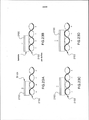
[00045] A Fig. 17A ilustra o caso em que a fita matriz é helicoidalmente enrolada em torno do cabo com a mesma camada de cordão de cabo que a experiência de pares de fios. Neste caso, a periodicidade dos formatos metálicos 1700 é igual para a periodicidade das dimensões (isto é, comprimento longitudinal e largura transversal) da própria fita.[00045] Fig. 17A illustrates the case in which the matrix tape is helically wound around the cable with the same layer of cable strand as the wire pair experiment. In this case, the periodicity of the 1700 metallic formats is the same for the periodicity of the dimensions (ie, longitudinal length and transverse width) of the tape itself.
[00046] A Fig. 17B ilustra o caso em que a fita matriz é enrolada em uma configuração longitudinal. Como mostrado aqui, a periodicidade dos formatos metálicos da fita 1700 é aproximadamente igual à diagonal dos formatos. Similarmente, a Fig. 17C ilustra um caso em que a periodicidade é mais complexa e, portanto, o cálculo para a frequência de acoplamento de modo diferencial coerente é mais complexo.[00046] Fig. 17B illustrates the case where the matrix ribbon is wound in a longitudinal configuration. As shown here, the periodicity of the metallic formats of the 1700 tape is approximately equal to the diagonal of the formats. Similarly, Fig. 17C illustrates a case where the periodicity is more complex and, therefore, the calculation for the coupling frequency in a coherent differential mode is more complex.
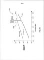
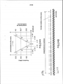
[00047] A Fig. 18 é um gráfico 1800 mostrando a especificação NEXT estranha de soma de potência (PSANEXT) 1802 e um nível de resposta de cabo 1804 para uma construção de cabo empregando uma fita matriz tendo uma periodicidade de formato metálico específico, de modo que exista um elevado nível de acoplamento de modo diferencial coerente 1806 próximo de 440 MHz entre dois cabos similarmente construídos; Este projeto de cabo particular ilustrado não atende a especificação que é requerida para aplicações U/UTP Cat 6A 10G Base-T. Observa-se que o desempenho de diafonia estranha externa do acoplamento de pico a 440 MHz satisfaz a especificação muito bem com significativa margem. Com uma modificação para o comprimento da periodicidade dos formatos metálicos e/ou uma mudança no comprimento das camadas de par de fios, como descrito abaixo e usado na presente invenção, o elevado grau de acoplamento mostrado no gráfico 1800 pode ser eliminado.[00047] Fig. 18 is a
[00048] Há dois mecanismos de acoplamento fundamentais em que diafonia estranha pode ocorrer entre pares de fios torcidos em dois similarmente diferentes cabos construídos: um acoplamento radioativo eletromagnético e um mecanismo e acoplamento não radioativo baseado em acoplamento capacitivo e indutivo. Os mecanismos não-radioativos dominam quanto à diafonia estranha, principalmente devido a proximidade de cabos vizinhos e a faixa de frequência de interesse (por exemplo, 1 MHz a 500 MHz). A seguinte discussão é direcionada a estes mecanismos de acoplamento não-radioativo. Um entendimento destes mecanismos de acoplamento ajuda na compreensão da natureza do acoplamento de modo diferencial coerente.[00048] There are two fundamental coupling mechanisms in which strange crosstalk can occur between pairs of wires twisted into two similarly constructed cables: an electromagnetic radioactive coupling and a non-radioactive coupling and mechanism based on capacitive and inductive coupling. Non-radioactive mechanisms dominate with regard to strange crosstalk, mainly due to the proximity of neighboring cables and the frequency range of interest (for example, 1 MHz to 500 MHz). The following discussion is directed at these non-radioactive coupling mechanisms. An understanding of these coupling mechanisms helps to understand the nature of coupling in a coherent differential manner.
[00049] As Figuras 19A-D e 20A-D são diagramas conceituais ilustrando mecanismos de acoplamento de diafonia estranha de modo diferencial e modo comum para cabos U/UTP sem (Figs. 19A, C) e com (Figs. 19B, D e 20A-D) a incorporação de fita matriz. As figuras ilustram como a fita matriz (um ajuste periódico descontínuo de formato metálico) pode prover atenuação a estes mecanismos de acoplamento.[00049] Figures 19A-D and 20A-D are conceptual diagrams illustrating differential crosstalk coupling mechanisms in a differential and common mode for U / UTP cables without (Figs. 19A, C) and with (Figs. 19B, D and 20A-D) the incorporation of matrix tape. The figures illustrate how the matrix tape (a periodic discontinuous adjustment of metallic shape) can provide attenuation to these coupling mechanisms.
[00050] Nas Figs. 19A-D, as magnitudes dos acoplamentos são representadas pelo comprimento e nitidez das setas (em que um comprimento maior e/ou uma seta mais nítida iguala-se a uma magnitude mais elevada). O acoplamento DM domina sobre o acoplamento CM em um cabo U/UTP típico, em razão do sinal de propagação no par de fios ser DM e a conversão de DM em CM ser tão fraca (por exemplo, -40 dB).[00050] In Figs. 19A-D, the magnitudes of the couplings are represented by the length and sharpness of the arrows (where a longer length and / or a sharper arrow equals a higher magnitude). The DM coupling dominates over the CM coupling on a typical U / UTP cable, because the propagation signal in the wire pair is DM and the conversion from DM to CM is so weak (for example, -40 dB).
[00051] A Fig. 19B mostra que o acoplamento DM (tanto elétrico como magnético) é muito reduzido (daquele mostrado na Fig. 19A), quando a fita matriz é incorporada dentro do cabo. Os mecanismos de atenuação responsáveis são descritos nas Figs. 20A e 20C. Similarmente, a Fig. 19D mostra que o acoplamento elétrico (capacitivo) CM é ligeiramente aumentado e o acoplamento magnético (indutivo) CM é ligeiramente reduzido. Os mecanismos de atenuação responsáveis são descritos nas Figs. 20B e 20D. As Figs. 20A-D não serão descritas em mais detalhes.[00051] Fig. 19B shows that the DM coupling (both electrical and magnetic) is very small (from that shown in Fig. 19A), when the matrix tape is incorporated inside the cable. The responsible attenuation mechanisms are described in Figs. 20A and 20C. Similarly, Fig. 19D shows that the electrical (capacitive) coupling CM is slightly increased and the magnetic (inductive) coupling CM is slightly reduced. The responsible attenuation mechanisms are described in Figs. 20B and 20D. Figs. 20A-D will not be described in more detail.
[00052] As Figs. 20A-D ilustram dois mecanismos de atenuação. As Figs. 20A e 20C ilustram acoplamento magnético e elétrico de modo diferencial, enquanto as Figs. 20B e 20D ilustram acoplamento magnético e elétrico de modo comum.[00052] Figs. 20A-D illustrate two mitigation mechanisms. Figs. 20A and 20C illustrate magnetic and electrical coupling in a differential way, while Figs. 20B and 20D illustrate common-mode magnetic and electrical coupling.
[00053] Para acoplamento magnético (indutivo) surgindo da corrente diferencial no par de fios 2000 (como mostrado na Fig. 20A) entre dois pares de fios torcidos 2000 e outro par de fios (não mostrado) em dois diferentes, porém, similarmente cabos construídos, uma corrente parasita 2004 é criada onde o campo magnético 2006 passa através dos formatos metálicos 2008. Esta corrente parasita provê perda de força (em uma taxa da resistência multiplicada pelo quadrado da corrente) para o campo magnético 2006 e, portanto, reduz a diafonia estranha associada com o acoplamento magnético. A Fig. 20C mostra como a magnitude do campo elétrico é atenuada, devido a um sinal de modo diferencial no par de fios 2000. O formato metálico 2008 provê um potencial substancialmente igual através do comprimento do par de fios 2000 que o formato metálico 2008 reveste e, assim, provê um efeito de mediação sobre o comprimento da cobertura. O valor potencial igual tende para zero quando o comprimento coberto aproxima-se de um múltiplo de número inteiro de períodos de par de fios. Similarmente, o valor potencial igual tende a uma magnitude máxima quando o comprimento coberto aproxima-se de um múltiplo de número semi-inteiro de períodos de par de fios. Diminuindo-se o valor potencial igual, diminui-se o acoplamento de campo elétrico entre pares de fios de diferentes cabos.[00053] For magnetic (inductive) coupling arising from the differential current in the wire pair 2000 (as shown in Fig. 20A) between two pairs of
[00054] Com respeito ao acoplamento de modo comum, as Figs. 19C e 19D, mostradas como acoplamento de campo magnético, são ligeiramente atenuadas e o acoplamento de campo elétrico é real e ligeiramente aumentado. A Fig. 20B ilustra que a magnitude do campo magnético 2012 é somente ligeiramente atenuada devido ao formato do campo magnético. Isto é somente em razão do componente de vetor normal do campo magnético 2012, com referência ao formato metálico 2008, produzir uma corrente parasita 2014. Uma vez que o componente normal é menor do que o correspondente componente normal em um sinal DM, este resulta em uma menor atenuação. O acoplamento de campo elétrico é realmente mais forte devido ao tamanho do formato metálico 2008 que está revestindo um comprimento do par de fios 2000 em uma magnitude de potencial comum. Aqui, os formatos metálicos estão essencialmente atuando como um “dispersor” físico, desse modo provendo mais fácil acoplamento de cabo-para-cabo.[00054] With respect to the common mode coupling, Figs. 19C and 19D, shown as magnetic field coupling, are slightly attenuated and the electric field coupling is real and slightly enlarged. Fig. 20B illustrates that the magnitude of the
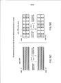
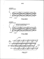
[00055] A descrição acima, dos mecanismos de acoplamento primário responsáveis por diafonia estranha, provê uma base para entendimento de que maneira o acoplamento de modo diferencial coerente pode ocorrer entre cabos de comunicação tendo fita matriz enrolada em espiral com formatos metálicos periódicos de comprimento fixado. As Figs. 21-25 são diagramas conceituais ilustrando ajustes em que o acoplamento de modo diferencial coerente pode ocorrer. Estas delineiam tijolos de referência (formatos metálicos) 2100 e pares torcidos 2102 e 2104.[00055] The above description of the primary coupling mechanisms responsible for foreign crosstalk provides a basis for understanding how coherent differential mode coupling can occur between communication cables having spiral ribbon matrix with periodic metallic shapes of fixed length . Figs. 21-25 are conceptual diagrams illustrating adjustments in which coherent differential coupling can occur. These outline reference bricks (metallic shapes) 2100 and
[00056] Como mostrado na Fig. 21A, para uma periodicidade de formato metálico particular (de comprimento L), existem camadas de par de fios torcidos (com periodicidade x) que produzem potenciais iguais não-zero nos formatos metálicos que compõem a fita matriz. Os potenciais iguais não- zero em tal relação periódica podem ter valores periódicos ao longo da direção longitudinal, com cada período tendo um comprimento periódico característico (“comprimento de coerência” 2106). As Figs. 22A-B e 23A-D ilustram isto simbolicamente, nas seções transversais oblíquas e longitudinais ao longo do comprimento do cabo, respectivamente. As Figs. 22A-B ilustram a carga relativa sobre o tijolo 2100, quando o par torcido 2102 torce sob o tijolo 2100. As Figs. 23A-D ilustram a carga relativa sobre o tijolo 2100, quando o comprimento L do tijolo 2100 muda em relação à camada par x do par torcido. Quando um sinal de modo diferencial é aplicado a um par de fios torcidos, que tem uma tal relação periódica entre seu comprimento de camada e com a periodicidade de formato metálico da fita matriz, um forte acoplamento pode resultar entre dois pares torcidos entre dois cabos similarmente construídos. O acoplamento entre os dois pares de dois diferentes cabos é largamente capacitivo, como mostrado na Fig. 21B. Este forte acoplamento capacitivo ocorre se o sinal aplicado for coerente com os potenciais iguais longitudinalmente periódicos (ou dito de outro modo, se o comprimento de onda do sinal aplicado for igual ao comprimento coerente 2106, como previamente definido e mostrado na Fig. 21A).[00056] As shown in Fig. 21A, for a periodicity of particular metallic shape (of length L), there are layers of twisted wire pairs (with periodicity x) that produce non-zero equal potentials in the metallic shapes that make up the matrix ribbon . Non-zero equal potentials in such a periodic relationship can have periodic values along the longitudinal direction, with each period having a characteristic periodic length ("coherence length" 2106). Figs. 22A-B and 23A-D illustrate this symbolically, in the oblique and longitudinal cross sections along the length of the cable, respectively. Figs. 22A-B illustrate the relative load on
[00057] O comprimento coerente 2106 (definido como o período dos potenciais periódicos iguais) indica em que frequência de sinal um grande acoplamento existe entre cabos vizinhos de construção similar. É preferido que esta frequência de sinal (se ela existir) seja fora da faixa de frequência de interesse. A faixa de frequência de interesse é a faixa de frequência da aplicação que o cabo está transmitindo (por exemplo, cabos de Base-T 10 Gb/s têm uma faixa de frequência de aplicação entre 1 e 500 MHz). Assim, é desejável produzir um comprimento de coerência 2106, de modo que a frequência de sinal pertinente seja fora da faixa de frequência da aplicação sendo transmitida.[00057] The coherent length 2106 (defined as the period of the equal periodic potentials) indicates at which signal frequency a large coupling exists between neighboring cables of similar construction. It is preferred that this signal frequency (if any) is outside the frequency range of interest. The frequency range of interest is the frequency range of the application that the cable is transmitting (for example, Base-
[00058] Para projetar um cabo em que a frequência de sinal em que o acoplamento de modo diferencial coerente ocorre está fora da faixa de frequência de interesse, pode-se ajustar valores para L e x (definidos acima). A relação entre o comprimento de coerência 2106 e a frequência de sinal e: Frequência (Hz) = (velocidade de fase) / (comprimento de coerência) A velocidade de fase é a velocidade de propagação do sinal de modo diferencial dentro do par de fios torcidos. Tipicamente, esta velocidade (que é meio dependente) é na ordem de 20 cm/ns. Portanto, se um comprimento de coerência de 60 cm ocorreu, então a frequência de elevado acoplamento é de aproximadamente 333 MHz. Isto pareceria igual ao pico PSANEXT 1806, mostrado na Fig. 18, exceto que ocorreria a 333 MHz.[00058] To design a cable in which the signal frequency in which coherent differential mode coupling occurs is outside the frequency range of interest, values for L and x (defined above) can be adjusted. The relationship between the 2106 coherence length and the signal frequency e: Frequency (Hz) = (phase speed) / (coherence length) The phase speed is the speed of propagation of the signal differentially within the wire pair twisted. Typically, this speed (which is somewhat dependent) is on the order of 20 cm / ns. Therefore, if a coherence length of 60 cm has occurred, then the high coupling frequency is approximately 333 MHz. This would appear to be equal to the
[00059] A fim de criar esta forma de acoplamento coerente, a periodicidade L dos formatos de metal 2100 compondo a fita matriz deve ser um múltiplo de número inteiro ou múltiplo de semi-inteiro do comprimento de camada de par de fios torcidos x. Além disso, quando esta condição existe, o comprimento de coerência resultante 2106 é dependente da diferença de comprimento δ entre o comprimento de camada do par de fios torcidos x e a periodicidade de formato metálico L. Esta diferença de comprimento δ é igual à magnitude de L menos x. Assim, quando L é exatamente igual a um múltiplo de x (isto é, δ = 0), o comprimento de coerência resultante é grande (e a frequência é muito baixa). Entretanto, se houver uma leve diferença ou desvio entre L e um múltiplo de x (isto é, δ não for zero), o comprimento de coerência resultante pode ser mais curto (a frequência será maior) ou mais longa (a frequência será menor).[00059] In order to create this form of coherent coupling, the periodicity L of the
[00060] As Figs. 24A-D ilustram as frequências em que o acoplamento de modo diferencial coerente ocorre para diferentes múltiplos de δ (L menos X), quando L=2x. Esta relação pode ser usada para construir um guia de projeto para escolher valores “próprios” de L e x (observa-se que todos os pares de fios torcidos devem conformar-se a este guia de projeto). Os limites para o comprimento de camada de par de fios torcidos x são de modo que a frequência resultante (quando derivada do comprimento de coerência) seja menor do que a frequência mais larga utilizada na aplicação que é projetada para. Por exemplo, em aplicações de Base-T 10G, a frequência mais larga especificada é de 500 MHz e, portanto, a camada de pares de fios torcidos pode ser selecionada dos valores que não resultam de uma frequência coerente de menos do que 500 MHz. Portanto, o maior valor aceitável para o comprimento de coerência que suporta esta aplicação é de 40 cm.[00060] Figs. 24A-D illustrate the frequencies at which coherent differential mode coupling occurs for different multiples of δ (L minus X), when L = 2x. This relationship can be used to build a design guide to choose “proper” values of L and x (note that all twisted wire pairs must conform to this design guide). The limits for the layer length of twisted wire pair x are such that the resulting frequency (when derived from the coherence length) is less than the wider frequency used in the application it is designed for. For example, in Base-T 10G applications, the widest frequency specified is 500 MHz and therefore the layer of twisted wire pairs can be selected from values that do not result from a coherent frequency of less than 500 MHz. Therefore, the highest acceptable value for the coherence length that this application supports is 40 cm.
[00061] Os conceitos acima podem ser usados para criar um gráfico de comprimentos de camada de torção “keep-out” para uma dada periodicidade de formatos metálicos. A Fig. 25A ilustra um exemplo 2300 de tal gráfico. A Fig. 25B mostra um exemplo de ajuste de camada de par torcido 2302 que se conforma a esta diretriz de projeto. De acordo com esta diretriz, cabos vizinhos não experimentam elevado acoplamento de modo diferencial coerente acima de e incluindo a frequência de aplicação máxima de 500 MHz.[00061] The above concepts can be used to create a "keep-out" tier layer length chart for a given periodicity of metallic shapes. Fig. 25A illustrates an example 2300 of such a graph. Fig. 25B shows an example of twisted
[00062] Há uma restrição sobre o máximo de periodicidade de comprimento metálico da fita matriz L, de modo que se o comprimento L for longo o bastante, então o acoplamento terá uma pequena amplitude e uma largura de banda ampla. Por exemplo, o comprimento de onda para um de sinal de modo diferencial propagando-se sobre os pares de fios torcidos a 200 MHz é de aproximadamente 100 cm. Quando a periodicidade de formato metálico da fita matriz L é na ordem de 2,54 cm, cerca de 40 formatos metálicos 2100 compõem um comprimento de coerência 2106 nesta frequência. O espectro de resposta resultante tem uma amplitude significativamente larga e uma estreita largura de banda. Entretanto, se a periodicidade de formato fosse na ordem de 25,4 cm, haveria somente quatro formatos que poderiam compor um comprimento de coerência na mesma frequência. Se um acoplamento de modo diferencial coerente fosse existir empregando-se esta periodicidade de formato metálico L de 24,4 cm, a resposta de diafonia estranha teria um pico com uma amplitude menor, com uma ampla largura de banda.[00062] There is a restriction on the maximum periodicity of metallic length of the matrix tape L, so that if the length L is long enough, then the coupling will have a small amplitude and a wide bandwidth. For example, the wavelength for a differential mode signal propagating over the 200 MHz twisted wire pairs is approximately 100 cm. When the periodicity of metallic format of the matrix tape L is in the order of 2.54 cm, about 40
[00063] Também se observa que a periodicidade de formato metálico tem um limite superior devido à susceptibilidade (e emissões) de energia eletromagnética radioativa. Este limite superior é principalmente válido (ou importante) somente no caso em que o par de fios 2102 tem um baixo equilíbrio (isto é, conversão DM em CM ou CM em DM dentro do cabo ou dentro da conectividade do canal). Os efeitos na emissão são quando um sinal CM é convertido em DM e, portanto, aparece como um contribuinte de ruído, ou quando um sinal DM se converte em um sinal CM e irradia (isto é, para um cabo vizinho). Quando o comprimento periódico de formato metálico L tem uma relação de múltiplo número inteiro para a frequência máxima que ele deve suportar, então a fita matriz irradia energia de ou em um sinal de modo comum propagando-se sobre o par de fios 2102. Por exemplo, a 500 MHz, o comprimento de onda é cerca de 40 cm para um sinal de modo comum propagando-se sobre o par de fios torcidos 2102. Se o comprimento periódico L dos formatos metálicos 2100 for na ordem de 10 cm (o que corresponde a uma antena de um quarto de comprimento de onda), então a fita matriz eficientemente irradia energia afastada do cabo. Naturalmente, este sistema tem reciprocidade, de modo que a fita matriz possa receber esta energia radioativa de uma fonte externa ou de outro cabo similarmente construído. Caso contribua para indesejável diafonia estranha.[00063] It is also observed that the periodicity of metallic format has an upper limit due to the susceptibility (and emissions) of radioactive electromagnetic energy. This upper limit is mainly valid (or important) only in the case where the
[00064] Além disso, para os limites superiores do comprimento periódico de formato metálico L, há também um limite inferior que é principalmente ajustado pelo comprimento de camada x do par de fios torcidos 2102. A atenuação de campo eletromagnético é reduzida, quando o comprimento de formato metálico L aproxima-se (ou é menor do que) daquele de um comprimento de camada de par de fios torcidos x. Esta sensibilidade é novamente controlada pela atenuação atribuída ao campo elétrico e ao campo magnético. Por exemplo, se os formatos metálicos 2100 tiverem comprimentos na ordem de metade do comprimento de par de fios torcidos x, então há um mínimo de atenuação de campo elétrico benéfico devido à ausência da segunda metade do comprimento de par de fios que compensa quanto à primeira metade. A atenuação benéfica de acoplamento de campo magnético é também diminuída quando o comprimento de formato metálico L é menor do que o comprimento da camada de par de fios x. A atenuação reduzida é devida principalmente a uma quantidade aumentada de bordas de formato metálico onde a corrente parasita não pode instalar-se eficazmente.[00064] In addition, for the upper limits of the periodic length of metallic shape L, there is also a lower limit that is mainly adjusted by the length of layer x of the twisted
[00065] Além disso, variando o comprimento periódico de formato metálico ou o comprimento de camada x, outra técnica envolve utilizar a variabilidade inerente em uma posição do par de fios (circunferencialmente no cabo) sob um formato metálico particular (isto é, tijolo). Esta variação posicional pode ser na ordem de 60 mils. Como mostrado na Fig. 26A, para um padrão de tijolo “retangular”, a variação posicional do par de fios 2102 não muda na região do par de fios que o tijolo 2100 reveste. Entretanto, como mostrado na Fig. 26B, para um padrão de tijolo paralelogramo não-regular, a variação posicional do par de fios 2102 pode variar na região do par de fios que o tijolo reveste, mudando o valor da carga aumentada e ajudando a dispersar qualquer distribuição de carga longitudinal periódica que poderia conduzir ao acoplamento de modo diferencial coerente.[00065] In addition, varying the periodic length of metallic shape or the length of layer x, another technique involves using the variability inherent in a position of the wire pair (circumferentially in the cable) under a particular metallic shape (ie, brick) . This positional variation can be in the order of 60 mils. As shown in Fig. 26A, for a “rectangular” brick pattern, the positional variation of
[00066] A Fig. 27 mostra um tal padrão de tijolos, paralelogramo não- regular 2100, alinhados com respectivos pares de fios 2102. Se o ângulo do paralelogramo for de 20 graus, então, para uma carga de 60 mils, na posição do par de fios, o comprimento do par de fios é comutado por cerca de 22 mils. Esta comutação de 22 mils representa cerca de 5 % de um comprimento do par de fios típico, que ajuda a reduzir a amplitude do pico de acoplamento de modo diferencial coerente e, desse modo, aumenta sua largura de banda (o pico é essencialmente reduzido e a largura de pico tende a dispersar-se). As Figs. 28A-C ilustram a variação de carga que pode ocorrer se a comutação de comprimento for na ordem de mais ou menos 10 % do comprimento de camada do par de fios. Aumentando o ângulo do paralelogramo, ainda aumenta-se esta variação.[00066] Fig. 27 shows such a brick pattern,
[00067] Em resumo, para evitar acoplamento de modo diferencial coerente em cabos utilizando fita matriz, pode-se usar uma ou mais das seguintes técnicas: (1) selecionar o comprimento de camada do par e o comprimento de periodicidade dos formatos metálicos fixados que resultem em um comprimento de coerência aceitável (usando-se os princípios fornecidos acima): (2) introduzir aleatoriedade ou suficiente pseudoaleatoriedade no padrão de formato metálico, dimensões de formato metálico individuais, ou comprimento de camada par, ou (3) escolher a esmo a camada de filamento de fita matriz com respeito às camadas de filamento dos pares de fios. Outras técnicas similares podem também ser possíveis e podem ser abrangidas por uma ou mais formas de realização da presenteinvenção.[00067] In summary, to avoid coherently differential coupling on cables using matrix tape, one or more of the following techniques can be used: (1) select the layer length of the pair and the periodicity length of the fixed metallic formats that result in an acceptable coherence length (using the principles provided above): (2) introduce randomness or sufficient pseudo-randomness into the metallic shape pattern, individual metallic shape dimensions, or even layer length, or (3) choose randomly the filament layer of matrix tape with respect to the filament layers of the wire pairs. Other similar techniques may also be possible and may be covered by one or more embodiments of the present invention.
[00068] Se uma impedância longitudinal do cabo for muito fraca, um sinal de modo comum pode propagar-se nos formatos metálicos da fita matriz (tijolos), potencialmente fazendo o cabo irradiar e tornar-se susceptível à radiação eletromagnética. Para minimizar a susceptibilidade ou radiação de EMC, a impedância longitudinal deve ser aumentada.[00068] If a longitudinal impedance of the cable is too weak, a common mode signal can propagate in the metallic formats of the matrix tape (bricks), potentially causing the cable to radiate and become susceptible to electromagnetic radiation. To minimize the susceptibility or radiation of EMC, the longitudinal impedance should be increased.
[00069] Como será descrito com referência às Figs. 29A-C e 30A-C, a impedância longitudinal de um cabo enrolado em fita matriz pode ser aumentada, escolhendo-se o padrão de formatos metálicos sobre a fita matriz para ser um padrão regular de formatos metálicos de paralelogramo não- regular. Isto, por sua vez, reduz a capacitância de sobreposição (entre dois formatos metálicos sobrepondo-se nos lados opostos do formato metálico) e a capacitância de sobreposição enrolada em espiral (entre dois formatos metálicos que são trazidos em uma configuração de sobreposição devido à fita matriz sendo enrolada ao longo do núcleo de cabo). A capacitância de sobreposição enrolada em espiral (Figs. 29A-B e 30A-B) será geralmente o componente dominante da impedância longitudinal, em razão de representar uma capacitância que se estende de um tijolo para outro tijolo, localizada em alguns tijolos afastados longitudinalmente.[00069] As will be described with reference to Figs. 29A-C and 30A-C, the longitudinal impedance of a cable wrapped in matrix tape can be increased by choosing the pattern of metallic shapes over the matrix tape to be a regular pattern of non-regular parallelogram metal shapes. This, in turn, reduces the overlap capacitance (between two metallic shapes overlapping on opposite sides of the metallic shape) and the spiral wound overlap capacitance (between two metallic shapes that are brought in in an overlap configuration due to the tape matrix being wound along the cable core). The spiral-wound overlap capacitance (Figs. 29A-B and 30A-B) will generally be the dominant component of longitudinal impedance, because it represents a capacitance that extends from one brick to another brick, located in some longitudinally spaced bricks.
[00070] A Fig. 29A-C ilustra o caso em que formatos metálicos de paralelogramo regular (isto é, retângulos) são usados como os tijolos, enquanto a Fig. 30A-C ilustra o caso em que formatos metálicos de paralelogramo não-regular (isto é paralelogramo) são usados. Como pode ser visto nos diagramas de circuito equivalentes das Figs. 29C e 30C (em combinação com as Figs. 29B e 30B), a capacitância de sobreposição enrolada em espiral está essencialmente em paralelo com um cordão em série de capacitores. Com o cordão em série de capacitores, a capacitância total é reduzida proporcionalmente pelo número de capacitores que estão em série (portanto, tijolos mais curtos resultam em uma mais elevada impedância longitudinal desejável). Quando a capacitância de sobreposição enrolada em espiral é colocada em paralelo, ela aumenta a capacitância total, desse modo reduzindo a impedância longitudinal. Por outro lado, quando um padrão regular de paralelogramos não-regulares é utilizado (Figs. 30A-C), a capacitância de sobreposição enrolada em espiral é colocada em paralelo com um número menor de cordão em série de capacitores, resultando em uma diminuição na capacitância total e um correspondente aumento na impedância longitudinal. Isto, por sua vez, resultará em menos radiação e susceptibilidade eletromagnética.[00070] Fig. 29A-C illustrates the case where metallic shapes of regular parallelogram (ie rectangles) are used like bricks, while Fig. 30A-C illustrates the case where metallic shapes of non-regular parallelogram (ie parallelogram) are used. As can be seen in the equivalent circuit diagrams in Figs. 29C and 30C (in combination with Figs. 29B and 30B), the spiral wound overlap capacitance is essentially in parallel with a series of capacitor strands. With the series of capacitor strands, the total capacitance is reduced proportionally by the number of capacitors that are in series (therefore, shorter bricks result in a higher desirable longitudinal impedance). When the spiral-wound overlap capacitance is placed in parallel, it increases the total capacitance, thereby reducing the longitudinal impedance. On the other hand, when a regular pattern of non-regular parallelograms is used (Figs. 30A-C), the spiral wound overlap capacitance is placed in parallel with a smaller number of strands in series of capacitors, resulting in a decrease in total capacitance and a corresponding increase in longitudinal impedance. This, in turn, will result in less radiation and electromagnetic susceptibility.
[00071] O uso de fita matriz provê características de atenuação melhorada de benefício adicional, resultando em uma aumentada relação de sinal-para-ruído e outros benefícios que podem ser derivados desta (por exemplo, capacidade de taxa de dados do canal). Este espectro de atenuação melhorada resulta da reorientação dos campos eletromagnéticos (correspondendo a novas condições limite que a fita matriz oferece), que redistribui a densidade de corrente nos pares de fios. A redistribuição da densidade de corrente tem uma área de superfície de seção transversal aumentada que reduz a atenuação dentro dos pares de fios.[00071] The use of matrix tape provides enhanced attenuation characteristics for additional benefit, resulting in an increased signal-to-noise ratio and other benefits that can be derived from it (eg channel data rate capability). This improved attenuation spectrum results from the reorientation of the electromagnetic fields (corresponding to new limit conditions that the matrix tape offers), which redistributes the current density in the wire pairs. The current density redistribution has an increased cross-sectional surface area that reduces attenuation within the wire pairs.
[00072] O nível de sinal no lado receptor de um Equipamento de rede de ethernet é amplamente controlado pela atenuação dentro do cabo. Há dois contribuintes principais para perdas dentro de um cabo. Eles são (1) perda condutiva (condutividade e perda de condutor relacionadas ao diâmetro de cobre e aspereza de superfície) e (2) perda dielétrica (relacionada com a perda dentro do material dielétrico que circunda os fios de cobre). Colocar a fita matriz em estreita proximidade com os pares de fios muda os campos eletromagnéticos de serem concentrados entre os fios para serem ligeiramente mais espalhados (isto é, uma mais elevada densidade de campo elétrico terminará nos formatos metálicos). Isto ajuda por três razões principais. Primeiro, aumenta a área de seção transversal para densidade de corrente dentro do fio de cobre, o que reduz a perda condutiva. Segundo, reduz a perda dielétrica, quando uma parte do campo agora pode passar através do meio dielétrico de perda inferior. Terceiro, a fita matriz reduz a quantidade de campo eletromagnético que alcança o dielétrico do material de camisa externa, o que poderia de outro modo contribuir para perda dielétrica. As Figs. 31 e 32A-B proveem uma ilustração conceitual destes benefícios. Estas figuras admitirão um cabo 10 Gb/s com fita matriz, quatro pares de fios de cobre (~25 mil de cobre) com um dielétrico de polietileno (retardante de fogo) carregado-FR circundando o cobre (~46 mil de diâmetro), um espaçador de polietileno espumado separando os pares de fios (~15 mil de largura por 155 mil de comprimento), uma barreira de polipropileno ou polietileno espumado entre os pares de fios e a fita matriz (-10 mils de largura), e uma camisa (PVC) de polivinilcloreto externa (~16 mils) (Vide, por exemplo, Fig. 13).[00072] The signal level on the receiving side of an Ethernet network equipment is largely controlled by the attenuation inside the cable. There are two main contributors to losses within a cable. They are (1) conductive loss (conductivity and conductor loss related to copper diameter and surface roughness) and (2) dielectric loss (related to the loss within the dielectric material surrounding the copper wires). Placing the matrix tape in close proximity to the wire pairs changes the electromagnetic fields from being concentrated between the wires to being slightly more spread out (that is, a higher density of the electric field will end in metallic shapes). This helps for three main reasons. First, it increases the cross-sectional area for current density within the copper wire, which reduces conductive loss. Second, it reduces dielectric loss, when a part of the field can now pass through the lower loss dielectric medium. Third, the matrix tape reduces the amount of electromagnetic field that reaches the dielectric of the outer jacket material, which could otherwise contribute to dielectric loss. Figs. 31 and 32A-B provide a conceptual illustration of these benefits. These figures will admit a 10 Gb / s cable with matrix tape, four pairs of copper wires (~ 25 thousand copper) with a FR-loaded polyethylene (fire retardant) dielectric surrounding the copper (~ 46 thousand in diameter), a foamed polyethylene spacer separating the wire pairs (~ 15 thousand wide by 155 thousand long), a foamed polypropylene or polyethylene barrier between the wire pairs and the matrix tape (-10 mils wide), and a shirt (PVC) of external polyvinyl chloride (~ 16 mils) (See, for example, Fig. 13).
[00073] Os campos eletromagnéticos produzidos pelos pares de fios penetram o dielétrico condutor, o separador, a barreira e a fita matriz. Os campos eletromagnéticos são elevadamente reduzidos fora da fita matriz. Assim, a camisa externa e elementos externos ao cabo somente minimamente afetarão a atenuação dos pares de fios. A Fig. 31 mostra um gráfico 3100 descrevendo o espectro de atenuação de um cabo U/UTP que emprega a fita matriz 3102, um cabo U/UTP que não usa a fita matriz 3104, e a especificação TIA568 para atenuação 3106. Observa-se melhoria do espectro de atenuação para um cabo utilizando a fita matriz.[00073] The electromagnetic fields produced by the wire pairs penetrate the conductive dielectric, the separator, the barrier and the matrix tape. Electromagnetic fields are greatly reduced outside the matrix tape. Thus, the outer jacket and elements external to the cable will only minimally affect the attenuation of the wire pairs. Fig. 31 shows a
[00074] A Figura 32A é uma ilustração conceitual dos campos magnéticos 3200 que circundam um cabo U/UTP 3202 que não utiliza a fita matriz. Observa-se que a densidade de corrente 3204 dentro do fio de cobre 3206a-b distribui-se por si mesma de acordo com estes campos eletromagnéticos 3200. Esta distribuição de corrente de pequena área de seção transversal resultante 3204, no par de fios 3206a-b, é concentrada entre os fios e tem uma profundidade superficial de penetração no par de fios. Como mostrado na Fig. 32B, quando uma superfície condutiva (por exemplo, a fita matriz) é trazida próxima ao par de fios 3206a-b, os campos 3208 redistribuem-se, fazendo uma redistribuição de corrente 3210 dentro dos fios de cobre 3206a-b. Esta redistribuição produz uma grande área de seção transversal para condução e, portanto, uma menor quantidade de atenuação. Este mecanismo é responsável pela parte condutiva da redução de atenuação. A perda dielétrica é também reduzida, devido a esta redistribuição dos campos 3200, 3208, por meio do que os campos dispersam-se em partes de material dielétrico dentro do cabo, que tem fatores de dissipação inferiores. Esta redução das perdas condutiva e dielétrica dentro do cabo resulta em um desempenho mais elevado do desempenho de canal 10 Gb/s Ethernet, devido à melhorada relação de sinal-para-ruído.[00074] Figure 32A is a conceptual illustration of the 3200 magnetic fields surrounding a U /
[00075] A Fig. 33 é uma vista em seção transversal de outro cabo 130 tendo uma película em relevo 132 como a camada isolante entre os pares de fios torcidos 26 e a fita matriz 32. De acordo com algumas formas de realização, a película em relevo 132 está na forma de uma fita em relevo feita de um polímero, tal como polietileno, polipropileno ou etileno propileno fluorado (FEP). Em algumas formas de realização, a película em relevo 132 é feita de uma camada em relevo de polietileno ou polipropileno espumado. Polietileno retardante de fogo não espumado pode ser usado como o material de base. Gravar em relevo a película 132 provê uma camada isolante tendo uma espessura total maior do que a espessura do material de base da película. Isto produz uma espessura de camada maior por massa unitária do que películas sólidas ou espumadas não em relevo. A incorporação de mais ar na camada, via gravação em relevo, diminui a constante dielétrica da camada resultante, permitindo um menor diâmetro de cabo total em razão da menor constante dielétrica total da camada permitir um nível similar de desempenho, como uma camada mais espessa de um material tendo uma constante dielétrica mais elevada. O uso de uma película em relevo reduz o custo total do cabo, reduzindo-se a quantidade de material sólido no cabo, e também melhora o desempenho da queima do cabo, em razão de uma quantidade menor de material inflamável ser provida dentro do cabo do que se uma camada isolante sólida fosse usada. O uso de uma película em relevo como a camada isolante também foi constatado melhorar o desempenho de perda de inserção do cabo. Isolar camadas de acordo com a presente invenção pode ser em espiral ou de outro modo enrolada em torno de um núcleo de cabo.[00075] Fig. 33 is a cross-sectional view of another
[00076] A Fig. 34 é uma vista em planta de uma forma de realização de uma película em relevo 132. Vistas em detalhes laterais são também mostradas na Fig. 34. Na forma de realização mostrada na Fig. 34, a película em relevo 132 toma a forma de um padrão de repetição de quadrados estampados em relevo 140 em um material de base, tal como polietileno ou polipropileno espumado ou não espumado. Em uma forma de realização preferida, um material de película polimérica espumado é usado. A relação de alongamento da película em relevo 132 é a relação entre a espessura efetiva da película em relevo ie, e a espessura do material de base, IB. Relações de alongamento de até 5, por exemplo, com uma espessura de material de base de 3 mils e uma espessura efetiva de 15 mils para a película em relevo, são usadas de acordo com algumas formas de realização. Outras relações úteis incluem uma espessura de material de base de 3 mils e uma espessura efetiva de 14 mils; uma espessura de material de base de 5 mils e uma espessura efetiva de 15 mils. De acordo com algumas formas de realização, os materiais de base na faixa de 1,5 a 7 mils são estampados em relevo para espessuras efetivas de 8 mils a 20 mils. Enquanto quadrados estampados em relevo 140 são mostrados na Fig. 34, outros formatos podem ser usados, como uma combinação de diferentes formatos através do comprimento da película 132, incluindo o uso de gravação em relevo padronizada.[00076] Fig. 34 is a plan view of an embossed
[00077] As Figs. 35-39 ilustram uma forma de realização alternativa de uma camada de barreira, feita de uma fita perfurada, tal como uma fita de etileno propileno fluorado (FEP) perfurado ou politetrafluoroetileno (PTFE). Nesta forma de realização, a perfuração ou outra deformação da película sólida aumenta a espessura da película, deslocando material além do plano da película. A Fig. 35 (a) é uma vista lateral de uma camada de película 3500 sem perfurações, e a Fig. 35 (b) mostra a mesma película 3500 com perfurações 3502, que aumentam a espessura efetiva total da película. Como resultado desta perfuração com deformação, a espessura efetiva da camada de película é aumentada em aplicações de cabo. Isto resulta em uma espessura de barreira maior por massa unitária do que fita sólida. Também, usar a película 3500 como uma camada de barreira coloca mais ar entre os pares torcidos de um cabo e uma fita matriz, diminuindo a constante dielétrica da camada de barreira e resultando em uma menor espessura requerida da camada de barreira. Em razão da constante dielétrica total resultante da camada de barreira ser menor, o cabo pode ser manufaturado com um diâmetro menor. Além disso, uma redução na quantidade total de material no cabo diminui o custo total do cabo e melhora o desempenho de queima UL do cabo.[00077] Figs. 35-39 illustrate an alternative embodiment of a barrier layer, made of a perforated tape, such as a perforated fluorinated propylene ethylene (FEP) or polytetrafluoroethylene (PTFE) tape. In this embodiment, perforation or other deformation of the solid film increases the thickness of the film, displacing material beyond the plane of the film. Fig. 35 (a) is a side view of a 3500 film layer without perforations, and Fig. 35 (b) shows the same 3500 film with
[00078] Espessuras de película iniciais exemplares para uso em cabos de acordo com a presente invenção são de 0,0055” e 0,004”, embora, por exemplo, espessuras de 0,002” a 0,020” possam ser usadas. Em seguida à perfuração, a espessura efetiva da película (isto é, a distância de um “pico” de uma perfuração para a camada oposta da película) aumenta de aproximadamente um fator de dois. Esta duplicação efetiva de espessura é um tanto reduzida durante a construção de cabo, uma vez que a película perfurada é comprimida. Maiores ou menores aumentos de espessura efetivos podem serobtidos usando-se diferentes técnicas de perfuração.[00078] Exemplary initial film thicknesses for use in cables according to the present invention are 0.0055 ”and 0.004”, although, for example, thicknesses from 0.002 ”to 0.020” can be used. Following perforation, the effective thickness of the film (that is, the distance from a "peak" of a perforation to the opposite layer of the film) increases by approximately a factor of two. This effective doubling of thickness is somewhat reduced during cable construction, as the perforated film is compressed. Greater or lesser effective thickness increases can be achieved using different drilling techniques.
[00079] Um método de manufaturar uma película perfurada de acordo com a presente invenção é usar uma “matriz de agulha” aquecida para perfurar a película. O calor usado neste processo ajuda no “ajuste” da deformação de material resultante. A Fig. 36 mostra uma matriz de agulha aquecida rotativa 3602 e uma escova de rolo oposta 3604. Durante manufatura, o material a ser perfurado é alimentado entre a matriz de agulha rotativa 3602 e a escova de rolo 3604.[00079] One method of manufacturing a perforated film in accordance with the present invention is to use a heated "needle matrix" to perforate the film. The heat used in this process helps to “adjust” the resulting material deformation. Fig. 36 shows a rotating
[00080] As Figs. 37 e 38 mostram vistas em perspectiva de películas perfuradas 3500, tendo perfurações 3502 que são providas com um ajuste de deformação permanente.[00080] Figs. 37 and 38 show perspective views of
[00081] A Fig. 39 mostra uma seção transversal de um cabo 3900, tendo uma película perfurada 3500 provida com uma camada de barreira entre o núcleo de cabo (que pode incluir um separador 3902) e uma camada de fita matriz 32. Uma camisa 33 circunda a fita matriz 32.[00081] Fig. 39 shows a cross section of a 3900 cable, having a 3500 perforated film provided with a barrier layer between the cable core (which may include a 3902 separator) and a layer of
[00082] As fitas matrizes, de acordo com a presente invenção, podem ser em espiral ou de outro modo enroladas em torno de pares torcidos individuais dentro do cabo para melhorar a atenuação de diafonia entre os pares torcidos. Além disso, camadas barreira, de acordo com a presente invenção, podem ser incorporadas em diferentes estruturas dentro de um cabo, incluindo uma camada isolante, uma camisa isolante externa, ou uma estrutura divisora de par torcido.[00082] The master tapes according to the present invention can be spiral or otherwise wrapped around individual twisted pairs within the cable to improve crosstalk attenuation between the twisted pairs. In addition, barrier layers according to the present invention can be incorporated into different structures within a cable, including an insulating layer, an external insulating jacket, or a twisted pair divider structure.
[00083] Pelo precedente, pode ser visto que foram providos aspectos para desempenho melhorado de cabos para aumentar a atenuação de diafonia de cabo-para-cabo, enquanto também melhorando outras características eletromagnéticas. Embora formas de realização particulares da presente invenção tenham sido mostradas e descritas, será óbvio àqueles hábeis na arte que mudanças e modificações podem ser feitas sem afastar-se da invenção em seus aspectos mais amplos. Portanto, o objetivo é abranger todas tais mudanças e modificações quando se situam dentro do verdadeiro espírito e escopo da invenção. O assunto fornecido na descrição precedente e desenhos anexos é proposto por meio de ilustração somente e não como uma limitação.[00083] From the foregoing, it can be seen that aspects for improved cable performance have been provided to increase cable-to-cable crosstalk attenuation, while also improving other electromagnetic characteristics. Although particular embodiments of the present invention have been shown and described, it will be obvious to those skilled in the art that changes and modifications can be made without departing from the invention in its broadest aspects. Therefore, the objective is to cover all such changes and modifications when they are within the true spirit and scope of the invention. The subject provided in the preceding description and accompanying drawings is proposed by way of illustration only and not as a limitation.
Claims (13)
Applications Claiming Priority (7)
| Application Number | Priority Date | Filing Date | Title |
|---|---|---|---|
| US17596809P | 2009-05-06 | 2009-05-06 | |
| US61/175,968 | 2009-05-06 | ||
| US22964009P | 2009-07-29 | 2009-07-29 | |
| US61/229,640 | 2009-07-29 | ||
| US12/773,551 | 2010-05-04 | ||
| US12/773,551 US8445787B2 (en) | 2009-05-06 | 2010-05-04 | Communication cable with improved electrical characteristics |
| PCT/US2010/033739 WO2010129680A1 (en) | 2009-05-06 | 2010-05-05 | Communication cable with improved electrical characteristics |
Publications (2)
| Publication Number | Publication Date |
|---|---|
| BRPI1014565A2 BRPI1014565A2 (en) | 2016-04-19 |
| BRPI1014565B1 true BRPI1014565B1 (en) | 2020-12-29 |
Family
ID=42244085
Family Applications (1)
| Application Number | Title | Priority Date | Filing Date |
|---|---|---|---|
| BRPI1014565-6A BRPI1014565B1 (en) | 2009-05-06 | 2010-05-05 | method for designing a communication cable, and, communication cable |
Country Status (9)
| Country | Link |
|---|---|
| US (2) | US8445787B2 (en) |
| EP (1) | EP2427887B1 (en) |
| JP (2) | JP5563066B2 (en) |
| KR (1) | KR101783660B1 (en) |
| CN (1) | CN102498527B (en) |
| AU (1) | AU2010245926B2 (en) |
| BR (1) | BRPI1014565B1 (en) |
| TW (1) | TWI550645B (en) |
| WO (1) | WO2010129680A1 (en) |
Families Citing this family (40)
| Publication number | Priority date | Publication date | Assignee | Title |
|---|---|---|---|---|
| US9275776B1 (en) | 2006-08-11 | 2016-03-01 | Essex Group, Inc. | Shielding elements for use in communication cables |
| US9251930B1 (en) | 2006-08-11 | 2016-02-02 | Essex Group, Inc. | Segmented shields for use in communication cables |
| US9363935B1 (en) | 2006-08-11 | 2016-06-07 | Superior Essex Communications Lp | Subdivided separation fillers for use in cables |
| EP2143141A4 (en) | 2007-04-18 | 2011-04-13 | Invisage Technologies Inc | Materials systems and methods for optoelectronic devices |
| US20100044676A1 (en) | 2008-04-18 | 2010-02-25 | Invisage Technologies, Inc. | Photodetectors and Photovoltaics Based on Semiconductor Nanocrystals |
| US8203195B2 (en) | 2008-04-18 | 2012-06-19 | Invisage Technologies, Inc. | Materials, fabrication equipment, and methods for stable, sensitive photodetectors and image sensors made therefrom |
| JP5211304B2 (en) * | 2009-08-27 | 2013-06-12 | 東日京三電線株式会社 | Shielded communication cable |
| US8785782B2 (en) * | 2010-01-08 | 2014-07-22 | Hyundai Mobis Co., Ltd | UTP cable of improved alien crosstalk characteristic |
| US8916947B2 (en) | 2010-06-08 | 2014-12-23 | Invisage Technologies, Inc. | Photodetector comprising a pinned photodiode that is formed by an optically sensitive layer and a silicon diode |
| US20120312579A1 (en) * | 2011-06-10 | 2012-12-13 | Kenny Robert D | Cable jacket with embedded shield and method for making the same |
| US8900015B2 (en) | 2011-10-03 | 2014-12-02 | Panduit Corp. | Communication connector with reduced crosstalk |
| US9349507B2 (en) * | 2012-11-06 | 2016-05-24 | Apple Inc. | Reducing signal loss in cables |
| US9424964B1 (en) | 2013-05-08 | 2016-08-23 | Superior Essex International LP | Shields containing microcuts for use in communications cables |
| KR20150021181A (en) * | 2013-08-19 | 2015-03-02 | 엘에스전선 주식회사 | Communication cable comprising discontinuous shield tape and discontinuous shield tape |
| HUE036752T2 (en) * | 2013-10-23 | 2018-07-30 | Belden Inc | Improved high performance data communications cable |
| DE102014000897A1 (en) * | 2014-01-23 | 2015-07-23 | Rosenberger Hochfrequenztechnik Gmbh & Co. Kg | cable assembly |
| CN204322618U (en) * | 2014-12-01 | 2015-05-13 | 虞家桢 | A kind of mask tape |
| DE102015202708A1 (en) * | 2015-02-13 | 2016-08-18 | Leoni Kabel Holding Gmbh | Cable and method for its manufacture |
| WO2017056097A1 (en) * | 2015-10-02 | 2017-04-06 | ENBAR, Arie | Common mode noise suppression method and apparatus |
| US10593502B1 (en) | 2018-08-21 | 2020-03-17 | Superior Essex International LP | Fusible continuous shields for use in communication cables |
| US10102946B1 (en) | 2015-10-09 | 2018-10-16 | Superior Essex International LP | Methods for manufacturing discontinuous shield structures for use in communication cables |
| US10714874B1 (en) | 2015-10-09 | 2020-07-14 | Superior Essex International LP | Methods for manufacturing shield structures for use in communication cables |
| DE102016003134A1 (en) * | 2016-03-15 | 2017-09-21 | Rosenberger Hochfrequenztechnik Gmbh & Co. Kg | Cable for transmitting electrical signals |
| WO2018022725A1 (en) | 2016-07-26 | 2018-02-01 | General Cable Technologies Corporation | Cable having shielding tape wth conductive shielding segments |
| US9928943B1 (en) * | 2016-08-03 | 2018-03-27 | Superior Essex International LP | Communication cables incorporating separator structures |
| US10573431B2 (en) * | 2016-08-24 | 2020-02-25 | Ls Cable & System Ltd. | Communication cable |
| US10121571B1 (en) | 2016-08-31 | 2018-11-06 | Superior Essex International LP | Communications cables incorporating separator structures |
| US10068685B1 (en) | 2016-11-08 | 2018-09-04 | Superior Essex International LP | Communication cables with separators having alternating projections |
| US10276281B1 (en) | 2016-11-08 | 2019-04-30 | Superior Essex International LP | Communication cables with twisted tape separators |
| CN106448914A (en) * | 2016-12-15 | 2017-02-22 | 江苏戴普科技有限公司 | Rail transit flame-retardant four-pair shielded twisted-pair |
| US9741470B1 (en) | 2017-03-10 | 2017-08-22 | Superior Essex International LP | Communication cables incorporating separators with longitudinally spaced projections |
| US10438726B1 (en) | 2017-06-16 | 2019-10-08 | Superior Essex International LP | Communication cables incorporating separators with longitudinally spaced radial ridges |
| US10388435B2 (en) | 2017-06-26 | 2019-08-20 | Panduit Corp. | Communications cable with improved electro-magnetic performance |
| US10373740B2 (en) | 2017-08-09 | 2019-08-06 | Panduit Corp. | Communications cable with improved isolation between wire-pairs and metal foil tape |
| US10553333B2 (en) * | 2017-09-28 | 2020-02-04 | Sterlite Technologies Limited | I-shaped filler |
| US10517198B1 (en) * | 2018-06-14 | 2019-12-24 | General Cable Technologies Corporation | Cable having shielding tape with conductive shielding segments |
| EP3895187A4 (en) * | 2018-11-22 | 2023-02-08 | Sterlite Technologies Ltd | Telecommunications cable with twin jacket and barrier |
| CN110716521B (en) * | 2019-10-30 | 2021-01-08 | 苏州安驰控制系统有限公司 | Control method of stranding machine and stranding control system |
| US20230060912A1 (en) * | 2021-08-25 | 2023-03-02 | Panduit Corp. | Optimized wire separator for twisted wire-pair applications |
| CN115332841B (en) * | 2022-10-14 | 2022-12-30 | 深圳市爱特姆科技有限公司 | High-frequency large-current BTB connector convenient to manufacture |
Family Cites Families (19)
| Publication number | Priority date | Publication date | Assignee | Title |
|---|---|---|---|---|
| US2796463A (en) * | 1951-06-29 | 1957-06-18 | Bell Telephone Labor Inc | Composite conductors |
| US3312774A (en) * | 1965-02-10 | 1967-04-04 | John D Drinko | Semi-insulating shielding for cables and the like and comprising discrete "floating"patches of semi-conductive material |
| US3794750A (en) * | 1973-07-27 | 1974-02-26 | Boston Insulated Wire & Cable | Shielded cable |
| DE2636523A1 (en) * | 1976-08-13 | 1978-02-16 | Kabel Metallwerke Ghh | RADIATING HIGH FREQUENCY LINE |
| US4236779A (en) * | 1978-05-01 | 1980-12-02 | Bunker Ramo Corporation | EMI Shielded cable and connector assembly |
| JPS58131518U (en) | 1982-03-02 | 1983-09-05 | 昭和電線電纜株式会社 | electric cable |
| DE3637561A1 (en) * | 1985-11-18 | 1987-05-21 | Lisec Peter | Device for fitting flexible spacers on glass panels |
| SE450925B (en) * | 1985-12-06 | 1987-08-10 | Por Microtrans Ab | MICROVAGS ENERGY TRANSFER S APPLICATOR FOR 2.45 GHZ |
| JPS63171912U (en) | 1987-04-27 | 1988-11-09 | ||
| US5473336A (en) * | 1992-10-08 | 1995-12-05 | Auratek Security Inc. | Cable for use as a distributed antenna |
| US7154043B2 (en) * | 1997-04-22 | 2006-12-26 | Belden Technologies, Inc. | Data cable with cross-twist cabled core profile |
| DE102004042656B3 (en) * | 2004-09-03 | 2005-12-29 | Draka Comteq Germany Gmbh & Co. Kg | Multi-layer, strip-shaped shielding foil for electrical lines and thus equipped electrical cable, in particular data transmission cable |
| KR101127252B1 (en) * | 2005-03-28 | 2012-03-29 | 레비톤 메뉴팩튜어링 캄파니 인코포레이티드 | Discontinuous cable shield system and method |
| US7923641B2 (en) * | 2006-08-11 | 2011-04-12 | Superior Essex Communications LLP | Communication cable comprising electrically isolated patches of shielding material |
| KR20100017886A (en) | 2007-06-12 | 2010-02-16 | 팬듀트 코포레이션 | Communication channels with crosstalk-mitigating material |
| JP5277661B2 (en) * | 2008-02-26 | 2013-08-28 | 日立電線株式会社 | Cable with shielding layer |
| CA2717863C (en) * | 2008-03-06 | 2016-07-05 | Panduit Corp. | Communication cable with improved crosstalk attenuation |
| CN201197261Y (en) | 2008-05-05 | 2009-02-18 | 李论 | Aluminum foil polyester film tape |
| US8183462B2 (en) * | 2008-05-19 | 2012-05-22 | Panduit Corp. | Communication cable with improved crosstalk attenuation |
-
2010
- 2010-05-04 US US12/773,551 patent/US8445787B2/en active Active
- 2010-05-05 CN CN2010800290076A patent/CN102498527B/en active Active
- 2010-05-05 WO PCT/US2010/033739 patent/WO2010129680A1/en active Application Filing
- 2010-05-05 JP JP2012509949A patent/JP5563066B2/en active Active
- 2010-05-05 EP EP10718796.5A patent/EP2427887B1/en active Active
- 2010-05-05 TW TW099114380A patent/TWI550645B/en active
- 2010-05-05 AU AU2010245926A patent/AU2010245926B2/en active Active
- 2010-05-05 KR KR1020117029105A patent/KR101783660B1/en active IP Right Grant
- 2010-05-05 BR BRPI1014565-6A patent/BRPI1014565B1/en active IP Right Grant
-
2013
- 2013-05-20 US US13/897,776 patent/US9012778B2/en not_active Expired - Fee Related
-
2014
- 2014-02-10 JP JP2014023133A patent/JP5674970B2/en active Active
Also Published As
| Publication number | Publication date |
|---|---|
| AU2010245926B2 (en) | 2014-10-16 |
| JP2012526361A (en) | 2012-10-25 |
| US20130277090A1 (en) | 2013-10-24 |
| CN102498527A (en) | 2012-06-13 |
| TWI550645B (en) | 2016-09-21 |
| US8445787B2 (en) | 2013-05-21 |
| KR101783660B1 (en) | 2017-10-10 |
| EP2427887A1 (en) | 2012-03-14 |
| JP2014103126A (en) | 2014-06-05 |
| WO2010129680A1 (en) | 2010-11-11 |
| AU2010245926A1 (en) | 2011-11-24 |
| EP2427887B1 (en) | 2018-11-21 |
| US9012778B2 (en) | 2015-04-21 |
| JP5674970B2 (en) | 2015-02-25 |
| JP5563066B2 (en) | 2014-07-30 |
| AU2010245926A2 (en) | 2012-03-08 |
| BRPI1014565A2 (en) | 2016-04-19 |
| TW201126544A (en) | 2011-08-01 |
| KR20120027013A (en) | 2012-03-20 |
| US20100282493A1 (en) | 2010-11-11 |
| CN102498527B (en) | 2013-10-16 |
Similar Documents
| Publication | Publication Date | Title |
|---|---|---|
| BRPI1014565B1 (en) | method for designing a communication cable, and, communication cable | |
| TWI498922B (en) | Communication system, communication cable and barrier tape with improved crosstalk attenuation, and method for attenuating alien crosstalk between a plurality of communication cables | |
| AU2009249175B8 (en) | Communication cable with improved crosstalk attenuation | |
| JP5599809B2 (en) | Communication cable with improved crosstalk attenuation | |
| JP2020525971A (en) | Communication cable with improved electromagnetic performance |
Legal Events
| Date | Code | Title | Description |
|---|---|---|---|
| B06F | Objections, documents and/or translations needed after an examination request according [chapter 6.6 patent gazette] | ||
| B06U | Preliminary requirement: requests with searches performed by other patent offices: procedure suspended [chapter 6.21 patent gazette] | ||
| B09A | Decision: intention to grant [chapter 9.1 patent gazette] | ||
| B16A | Patent or certificate of addition of invention granted [chapter 16.1 patent gazette] |
Free format text: PRAZO DE VALIDADE: 10 (DEZ) ANOS CONTADOS A PARTIR DE 29/12/2020, OBSERVADAS AS CONDICOES LEGAIS. |