BRPI1011761B1 - RADIO COMMUNICATION DEVICES AND RADIO COMMUNICATION METHOD - Google Patents
RADIO COMMUNICATION DEVICES AND RADIO COMMUNICATION METHOD Download PDFInfo
- Publication number
- BRPI1011761B1 BRPI1011761B1 BRPI1011761-0A BRPI1011761A BRPI1011761B1 BR PI1011761 B1 BRPI1011761 B1 BR PI1011761B1 BR PI1011761 A BRPI1011761 A BR PI1011761A BR PI1011761 B1 BRPI1011761 B1 BR PI1011761B1
- Authority
- BR
- Brazil
- Prior art keywords
- phr
- channel
- data channel
- transmission mode
- control channel
- Prior art date
Links
- 238000004891 communication Methods 0.000 title claims abstract description 50
- 238000000034 method Methods 0.000 title claims abstract description 35
- 230000005540 biological transmission Effects 0.000 claims abstract description 237
- 230000011664 signaling Effects 0.000 abstract description 29
- 230000004069 differentiation Effects 0.000 abstract 1
- 238000010586 diagram Methods 0.000 description 26
- 238000004364 calculation method Methods 0.000 description 18
- 239000013256 coordination polymer Substances 0.000 description 17
- 230000007274 generation of a signal involved in cell-cell signaling Effects 0.000 description 8
- 238000013507 mapping Methods 0.000 description 7
- 238000001514 detection method Methods 0.000 description 5
- 238000006243 chemical reaction Methods 0.000 description 4
- 238000005516 engineering process Methods 0.000 description 4
- 230000006866 deterioration Effects 0.000 description 3
- 230000010354 integration Effects 0.000 description 3
- 101000741965 Homo sapiens Inactive tyrosine-protein kinase PRAG1 Proteins 0.000 description 2
- 102100038659 Inactive tyrosine-protein kinase PRAG1 Human genes 0.000 description 2
- 230000003321 amplification Effects 0.000 description 2
- 230000000694 effects Effects 0.000 description 2
- 239000000284 extract Substances 0.000 description 2
- 238000010304 firing Methods 0.000 description 2
- 238000003199 nucleic acid amplification method Methods 0.000 description 2
- 230000006978 adaptation Effects 0.000 description 1
- 230000007423 decrease Effects 0.000 description 1
- 238000009795 derivation Methods 0.000 description 1
- 230000002542 deteriorative effect Effects 0.000 description 1
- 230000014509 gene expression Effects 0.000 description 1
- 230000007774 longterm Effects 0.000 description 1
- 238000004519 manufacturing process Methods 0.000 description 1
- 239000011159 matrix material Substances 0.000 description 1
- 238000010295 mobile communication Methods 0.000 description 1
- NRNCYVBFPDDJNE-UHFFFAOYSA-N pemoline Chemical compound O1C(N)=NC(=O)C1C1=CC=CC=C1 NRNCYVBFPDDJNE-UHFFFAOYSA-N 0.000 description 1
- 238000013468 resource allocation Methods 0.000 description 1
- 239000004065 semiconductor Substances 0.000 description 1
Images


Classifications
-
- H—ELECTRICITY
- H04—ELECTRIC COMMUNICATION TECHNIQUE
- H04W—WIRELESS COMMUNICATION NETWORKS
- H04W52/00—Power management, e.g. TPC [Transmission Power Control], power saving or power classes
- H04W52/04—TPC
- H04W52/30—TPC using constraints in the total amount of available transmission power
- H04W52/36—TPC using constraints in the total amount of available transmission power with a discrete range or set of values, e.g. step size, ramping or offsets
- H04W52/365—Power headroom reporting
-
- H—ELECTRICITY
- H04—ELECTRIC COMMUNICATION TECHNIQUE
- H04L—TRANSMISSION OF DIGITAL INFORMATION, e.g. TELEGRAPHIC COMMUNICATION
- H04L1/00—Arrangements for detecting or preventing errors in the information received
- H04L1/0001—Systems modifying transmission characteristics according to link quality, e.g. power backoff
- H04L1/0023—Systems modifying transmission characteristics according to link quality, e.g. power backoff characterised by the signalling
- H04L1/0025—Transmission of mode-switching indication
-
- H—ELECTRICITY
- H04—ELECTRIC COMMUNICATION TECHNIQUE
- H04W—WIRELESS COMMUNICATION NETWORKS
- H04W72/00—Local resource management
- H04W72/04—Wireless resource allocation
- H04W72/044—Wireless resource allocation based on the type of the allocated resource
- H04W72/0473—Wireless resource allocation based on the type of the allocated resource the resource being transmission power
-
- H—ELECTRICITY
- H04—ELECTRIC COMMUNICATION TECHNIQUE
- H04W—WIRELESS COMMUNICATION NETWORKS
- H04W72/00—Local resource management
- H04W72/50—Allocation or scheduling criteria for wireless resources
- H04W72/53—Allocation or scheduling criteria for wireless resources based on regulatory allocation policies
-
- H—ELECTRICITY
- H04—ELECTRIC COMMUNICATION TECHNIQUE
- H04L—TRANSMISSION OF DIGITAL INFORMATION, e.g. TELEGRAPHIC COMMUNICATION
- H04L5/00—Arrangements affording multiple use of the transmission path
- H04L5/0001—Arrangements for dividing the transmission path
- H04L5/0003—Two-dimensional division
- H04L5/0005—Time-frequency
- H04L5/0007—Time-frequency the frequencies being orthogonal, e.g. OFDM(A), DMT
-
- H—ELECTRICITY
- H04—ELECTRIC COMMUNICATION TECHNIQUE
- H04L—TRANSMISSION OF DIGITAL INFORMATION, e.g. TELEGRAPHIC COMMUNICATION
- H04L5/00—Arrangements affording multiple use of the transmission path
- H04L5/003—Arrangements for allocating sub-channels of the transmission path
- H04L5/0053—Allocation of signaling, i.e. of overhead other than pilot signals
Abstract
aparelho de comunicação de rádio e metodo de comunicação de rádio. a presente invenção refere-se a um aparelho de estação móvel de comunicação de rádio, um aparelho de estação base de comunicação de rádio e um método de comunicação de rádio, que tornam possível comutar corretamente entre os modos de transmissão para um pusch e um pucch enquanto impedem que o overhad de sinalização aumente. uma unidade de ajuste de modo de transmissão (107) detecta uma instrução fornecida por uma estação base, a instrução que indica um método de multiplexação para um pusch e um a pucch. uma unidade de determinação de relatório de informação de disparo (108) realiza a diferenciação limítrole onde p-hr-pucch, que é calculada pela unidade de controle phr-control (106), é comparada a um valor limítrole que depende do método de multiplexação indicado pela instrução fornecida pela estação base. de maneira específica, em um modo de transmissão tdm as informações de disparo são relatadas se phr_pucch > x1[dbm] for satisfeita. por outro lado, em um modo de transmissão fdm as informações de disparo são relatadas se phr pucch < y1[dbm] for satisfeita. com base em um resultado da diferença limítrofe, a unidade de determinação de relatório de informações de disparo (108) determina se deve-se relatar as informações de disparo.radio communication apparatus and radio communication method. The present invention relates to a radio communication mobile station apparatus, a radio communication base station apparatus and a radio communication method, which make it possible to correctly switch between transmission modes for a push and a push while preventing signaling overload from increasing. a transmission mode adjustment unit (107) detects an instruction provided by a base station, the instruction indicating a multiplexing method for a pusch and a pucch. a trigger information report determination unit (108) performs threshold differentiation where p-hr-pucch, which is calculated by the phr-control control unit (106), is compared to a threshold value that depends on the multiplexing method. indicated by the instruction provided by the base station. Specifically, in a tdm transmission mode trigger information is reported if phr_pucch > x1[dbm] is satisfied. on the other hand, in an fdm transmission mode trigger information is reported if phr pucch < y1[dbm] is satisfied. Based on a result of the threshold difference, the trigger information reporting determination unit (108) determines whether to report the trigger information.
Description
A presente invenção refere-se a um aparelho de comunicação de rádio e um método de comunicação de rádio.The present invention relates to a radio communication apparatus and a radio communication method.
No Projeto de Parceria de 3a Geração de Evolução de Longo Prazo (3GPP LTE), no caso em que um canal de dados (canal compartilhado de enlace ascendente físico (PUSCH)) e um canal de controle (canal de controle de enlace ascendente físico (PUCCH)) são transmitidos no mesmo subquadro, uma estação móvel multiplexa os dois canais por multiplexação por divisão de tempo (TDM), conforme mostrado na Figura 1. Ou seja, os dados são perfurados por informações de controle, tal como, uma ACK ou uma NACK. Através da multiplexação TDM, é possível manter características de portadora exclusivas e evitar o aumento da métrica cúbica (CM). Por outro lado, devido ao fato de o dado ser perfurado, existe um problema em que o desempenho de recepção de dados deteriora.In the Long Term Evolution 3rd Generation Partnership Project (3GPP LTE), in the case where one data channel (physical uplink shared channel (PUSCH)) and one control channel (physical uplink control channel ( PUCCH)) are transmitted in the same subframe, a mobile station multiplexes the two channels by time division multiplexing (TDM), as shown in Figure 1. That is, the data is punctured by control information such as an ACK or a NACK. Through TDM multiplexing, it is possible to maintain unique carrier characteristics and avoid cubic metric (CM) increase. On the other hand, due to the fact that the data is punctured, there is a problem where the data reception performance deteriorates.
Em um canal de enlace ascendente de LTE-Advanced, que é uma versão desenvolvida do 3GPP LTE, no caso em que um PUSCH e um PUCCH são transmitidos no mesmo subquadro, espera-se que uma estação móvel multiplexe os dois canais por multiplexação por divisão de frequência (FDM), conforme mostrado na Figura 2. Uma estação móvel transmite um PUSCH e um PUCCH ao mesmo tempo ao mapear o PUSCH e o PUCCH em bandas de frequência diferentes. Devido ao fato de os dados não serem perfurados por multiplexação FDM, é possível evitar a deterioração do desempenho de recepção. Por outro lado, existe um problema em que as características de portadora exclusivas não são mantidas e a transmissão mul- tiportadora é realizada, de modo que a CM aumente. Quando a CM aumenta, a energia de transmissão máxima que pode ser transmitida por uma estação móvel diminui, de modo que a capacidade de energia (daqui por diante referida como a "capacidade de energia (PHR)") de uma estação móvel situ- ada, por exemplo, na borda de célula, se torne pequena, e não se torne possível ajustar a energia de transmissão requerida por uma estação base, reduzindo o desempenho de recepção da estação base de maneira significativa. PHR se refere à margem de energia de transmissão de uma estação móvel ou energia de transmissão de uma estação móvel que pode ser aumentada.In an LTE-Advanced uplink channel, which is a developed version of 3GPP LTE, in the case where a PUSCH and a PUCCH are transmitted in the same subframe, a mobile station is expected to multiplex the two channels by division multiplexing (FDM) as shown in Figure 2. A mobile station transmits a PUSCH and a PUCCH at the same time by mapping the PUSCH and PUCCH into different frequency bands. Due to the fact that the data is not punctured by FDM multiplexing, it is possible to avoid the deterioration of the reception performance. On the other hand, there is a problem where the unique carrier characteristics are not maintained and the multicarrier transmission is performed so that the CM increases. When the CM increases, the maximum transmit power that can be transmitted by a mobile station decreases, so that the power capacity (hereinafter referred to as the "power capacity (PHR)") of a situated mobile station , for example, at the cell edge, becomes small, and it becomes impossible to adjust the transmit power required by a base station, significantly reducing the base station's reception performance. PHR refers to the margin of transmit power of a mobile station or transmit power of a mobile station that can be increased.
Um método de multiptexaçãô de um PUSCH e um PUCCH em uma estação móvel, ou seja, um método no qual uma estação base controla se deve realizar a multiplexação por TDM (daqui por diante referida como "modo de transmissão TDM") ou realizar a multiplexação por FDM (daqui por diante referida como "modo de transmissão FDM") com base na PHR de uma estação móvel, se encontra sob consideração (por exemplo, vide Literatura de Não Patente 1). De maneira específica, no caso em que a PHR de uma estação móvel é grande (ou seja, a margem de energia de transmissão é grande), uma estação base aplica o modo de transmissão FDM, que não é submetido à influência de aumento de CM, a fim de evitar a deterioração do desempenho de recepção de PUSCH. Ademais, no caso em que a PHR de uma estação móvel é pequena (ou seja, a margem de energia de transmissão é pequena), uma estação base aplica o modo de transmissão TDM, a fim de evitar o aumento de CM e evitar a deterioração do desempenho de recepção de PUSCH.A method of multiplexing a PUSCH and a PUCCH in a mobile station, that is, a method in which a base station controls whether to perform TDM multiplexing (hereinafter referred to as "TDM transmission mode") or perform multiplexing by FDM (hereinafter referred to as "FDM transmission mode") based on the PHR of a mobile station is under consideration (for example, see Non-Patent Literature 1). Specifically, in the case where the PHR of a mobile station is large (i.e. the transmission power margin is large), a base station applies the FDM transmission mode, which is not subjected to the influence of increasing CM , in order to avoid deterioration of PUSCH reception performance. Furthermore, in the case where the PHR of a mobile station is small (ie the transmission power margin is small), a base station applies TDM transmission mode in order to avoid CM increase and avoid deterioration of PUSCH reception performance.
A Literatura de Não Patente 1 descreve que, no caso de aplicação do modo de transmissão FDM, é necessário assegurar preferencialmente a energia de transmissão de um PUCCH, para a qual o processamento de controle de retransmissão não é realizado a fim de requerer qualidade mais alta, comparada a um PUSCH. Ou seja, no modo de transmissão FDM, ao ajustar a razão entre a energia de transmissão de um PUSCH e um PUCCH, a energia de transmissão do PUCCH é assegurada primeiro, e a energia de transmissão de um PUSCH é ajustada dentro da faixa de energia de transmissão remanescente. Isto significa que, é possível evitar a deterioração do desempenho de um PUCCH, que requer qualidade mais alta.Non-Patent Literature 1 describes that, in the case of applying the FDM transmission mode, it is necessary to preferably ensure the transmission power of a PUCCH, for which the retransmission control processing is not performed in order to require higher quality , compared to a PUSCH. That is, in FDM transmission mode, by adjusting the ratio between the transmission energy of a PUSCH and a PUCCH, the transmission energy of the PUCCH is secured first, and the transmission energy of a PUSCH is adjusted within the energy range remaining transmission. This means that it is possible to avoid deteriorating the performance of a PUCCH, which requires higher quality.
Aqui, as definições e métodos de relatório de PHRs usadas na LTE serão descritas abaixo. Na LTE, conforme mostrado na Figura 3, apenas a PHR que é determinada com base na energia de transmissão de um PUSCH como uma referência, é definida. Na LTE, uma estação base usa a PHR para controlar a largura de banda de transmissão e o esquema de codificação de modulação e canal (MCS) de um PUSCH de uma estação móvel. Uma estação base pode receber um PUSCH com uma qualidade de recepção desejada pela estação base, ao controlar a largura de banda de transmissão e MCS de um PUSCH de uma estação móvel, de modo que a energia de transmissão de um PUSCH que é transmitida por uma estação móvel não exceda a energia de transmissão máxima da estação móvel.Here, the definitions and reporting methods of PHRs used in LTE will be described below. In LTE, as shown in Figure 3, only the PHR which is determined based on the transmit power of a PUSCH as a reference, is defined. In LTE, a base station uses the PHR to control the transmission bandwidth and modulation and channel coding scheme (MCS) of a PUSCH of a mobile station. A base station can receive a PUSCH with a reception quality desired by the base station, by controlling the transmission bandwidth and MCS of a PUSCH of a mobile station, so that the transmission energy of a PUSCH that is transmitted by a mobile station does not exceed the maximum transmit power of the mobile station.
A Literatura de Não Patente 2 descreve a definição de PHR e a condição de transmissão de PHR através da equação 1.
Na Equação 1, PHR_pusch é PHR [dB] com base em um PUSCH, e Pmax é a energia de transmissão máxima [dBm] de uma estação móvel. Ppusch da Equação 1 é a energia de transmissão de um PUSCH e é definida pela seguinte Equação 2.
Na Equação 2, M é o número de blocos de recurso de frequência a ser atribuído, Po é um valor [dBm] ajustado a partir de uma estação base, PL é um nível de perda de percurso [dB] medido por uma estação móvel, α é um coeficiente ponderado que mostra a taxa de compensação de perda de percurso, ΔMcs θ um deslocamento que depende do MCS, e f(Δ>) é um valor de controle de energia de transmissão para o qual o controle de circuito fechado é realizado (por exemplo, valores relativos de +3 dB ou -1 dB) e é o resultado da adição que inclui o valor de controle de energia de transmissão passado.In Equation 2, M is the number of frequency resource blocks to be assigned, Po is a value [dBm] set from a base station, PL is a path loss level [dB] measured by a mobile station, α is a weighted coefficient showing the path loss compensation rate, ΔMcs θ an offset that depends on the MCS, and f(Δ>) is a transmission power control value for which closed-loop control is performed ( for example, relative values of +3dB or -1dB) and is the result of the addition that includes the passed transmit power control value.
Po, α, e ΔMCSsão parâmetros a serem relatados a partir de uma estação base até uma estação móvel, e são valores que são conhecidos por uma estação base. Por outro lado, PL e f(Δj) são valores que não podem ser corretamente conhecidos por uma estação base. Embora f(Δi) seja um parâmetro a ser relatado a partir de uma estação base para uma estação móvel, existe um caso em que uma estação móvel não pode receber este comando (não pode detectar um canal de controle (PDCCH)). Devido ao fato de que uma estação base não pode determinar se uma estação móvel pode receber corretamente um comando ou não, uma vez que uma estação móvel falha para receber um valor de controle de energia de transmissão a partir de uma estação base, uma discrepância de reconhecimento entre a estação móvel e a estação base ocorre. Conforme descrito acima, devido ao fato de uma estação base não saber a PHR de uma estação móvel de maneira correta, a PHR precisa ser relatada a partir de uma.Po, α, and ΔMCS are parameters to be reported from a base station to a mobile station, and are values that are known to a base station. On the other hand, PL and f(Δj) are values that cannot be correctly known by a base station. Although f(Δi) is a parameter to be reported from a base station to a mobile station, there is a case where a mobile station cannot receive this command (cannot detect a control channel (PDCCH)). Due to the fact that a base station cannot determine whether a mobile station can correctly receive a command or not, once a mobile station fails to receive a transmit power control value from a base station, a discrepancy of recognition between the mobile station and the base station takes place. As described above, because a base station does not know the PHR of a mobile station correctly, the PHR needs to be reported from one.
A PHR é relatada a partir de uma estação móvel em um ciclo de-terminado antecipadamente por uma estação base. A PHR é relatada como informações de controle de acesso médio (MAC) de dados de transmissão através de um PUSCH que usa seis bits. Lista de Citação Literatura de Não Patente NPL 1 3GPP R1-090611, Samsung, "Concurrent PUSCH and PUCCH Transmissions" NPL 2 3GPP TS36.213 V8.5.0 7.1.6.1 Resource allocation type 0, "Physical layer procedures (Versão 8)"Sumário da Invenção Problema TécnicoPHR is reported from a mobile station in a cycle determined in advance by a base station. The PHR is reported as medium access control information (MAC) of transmission data over a PUSCH that uses six bits. Citation List Non-Patent Literature NPL 1 3GPP R1-090611, Samsung, "Concurrent PUSCH and PUCCH Transmissions" NPL 2 3GPP TS36.213 V8.5.0 7.1.6.1 Resource allocation type 0, "Physical layer procedures (Version 8)" Summary of the Invention Technical Problem
Uma estação base não pode mudar do modo de transmissão TDM para o modo de transmissão FDM, apenas ao usar a PHR descrita a- cima com base em um PUSCH (daqui por diante referido como "P- HR pusch"). Isto ocorre porque, no modo de transmissão FDM, uma estação base não pode controlar a largura de banda de transmissão e o MCS de um PUSCH de modo que a energia de transmissão não exceda a energia de transmissão máxima de uma estação móvel, apenas ao usar PHRpusch. Isto será descrito abaixo.A base station cannot switch from TDM transmission mode to FDM transmission mode only when using the PHR described above based on a PUSCH (hereinafter referred to as "P-HR push"). This is because, in FDM transmission mode, a base station cannot control the transmission bandwidth and MCS of a PUSCH so that the transmission energy does not exceed the maximum transmission energy of a mobile station, just when using PHRpusch. This will be described below.
No modo de transmissão FDM, conforme descrito acima, é necessário assegurar preferencialmente a energia de transmissão PUCCH. Ou seja, é necessário controlar a energia de transmissão de um PUSCH, que é determinada ao controlar a largura de banda de transmissão e o MCS do PUSCH, dentro da faixa de PHR que é determinada com base na energia de transmissão de um PUCCH como uma referência (daqui por diante referido como "PHR_pucch"). Quando a energia de transmissão de um PUSCH que é requerida por uma estação base excede a PHR_pucch de uma estação móvel, a energia de transmissão requerida para a transmissão simultânea de um PUSCH e um PUCCH excede a energia de transmissão máxima da estação móvel, de modo que a estação móvel não possa transmitir um PUSCH com a energia de transmissão requerida pela estação base. Portanto, não se torna possível receber um PUSCH com a qualidade de recepção desejada assumida pela estação base, reduzindo o desempenho de recepção de um PUSCH.In the FDM transmission mode, as described above, it is necessary to preferably secure the PUCCH transmission power. That is, it is necessary to control the transmit power of a PUSCH, which is determined by controlling the transmission bandwidth and MCS of the PUSCH, within the PHR range that is determined based on the transmit power of a PUCCH as a reference (hereafter referred to as "PHR_pucch"). When the transmission energy of a PUSCH that is required by a base station exceeds the PHR_pucch of a mobile station, the transmission energy required for simultaneous transmission of a PUSCH and a PUCCH exceeds the maximum transmission energy of the mobile station, so that the mobile station cannot transmit a PUSCH with the transmit power required by the base station. Therefore, it is not possible to receive a PUSCH with the desired reception quality assumed by the base station, reducing the reception performance of a PUSCH.
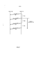
Por este motivo, é desejável que PHR_pucch, além de P- HR pusch, sejam relatadas a partir de uma estação móvel para uma estação base. Entretanto, no caso em que PHR_pucch é simplesmente relatada além de PHR pusch, o overhead de sinalização duplica conforme mostrado no diagrama de sequência da Figura 4. Devido ao fato de a PHR da LTE ser relatada em dB na faixa de -23 a 40 dB, a quantidade de sinalização requerida para uma PHR é de seis bits, conforme mostrado na Figura 4.For this reason, it is desirable that PHR_pucch, in addition to P-HRpusch, are reported from a mobile station to a base station. However, in the case where PHR_pucch is simply reported in addition to PHR pusch, the signaling overhead doubles as shown in the sequence diagram in Figure 4. Due to the fact that LTE PHR is reported in dB in the range of -23 to 40 dB , the amount of signaling required for a PHR is six bits, as shown in Figure 4.
Por outro lado, na LTE, as energias de transmissão de um PUSCH e um PUCCH são separadamente controladas. Portanto, não é possível determinar corretamente a PHRpucch a partir da PHR_pusch. Ademais, no caso de calcular a PHR pucch em uma estação base, existe o seguinte problema.On the other hand, in LTE, the transmission energies of a PUSCH and a PUCCH are separately controlled. Therefore, it is not possible to correctly determine the PHRpucch from the PHR_pusch. Furthermore, in the case of calculating the PHR pucch in a base station, there is the following problem.
A PHR_pucch é definida pela seguinte Equação 3. Ademais, Ppucch da Equação 3 é a energia de transmissão de um PUCCH, e é definido pela Equação 4.
Na Equação 4, Po_Pucch θ urn valor [dBm] ajustado por uma estação base, h e ΔpuCch são valores determinados que dependem do formato de transmissão de um PUCCH, e g(Δi) é um valor de controle de energia de transmissão para o qual o controle de circuito fechado é realizado e é o resultado da adição que inclui o valor de controle de energia de transmissão passado. Devido ao fato de PL ser o resultado medido por uma estação móvel, uma estação base não pode conhecer PL. Ademais, referindo-se a g(Δj), como no caso de f(Δj) na Equação 2, uma estação base não pode determinar se uma estação móvel pode reconhecer um comando corretamente ou não.In Equation 4, Po_Pucch θ a value [dBm] set by a base station, h and ΔpuCch are determined values that depend on the transmission format of a PUCCH, and g(Δi) is a transmission power control value for which the control Closed-loop control is performed and is the result of the addition that includes the passed transmission power control value. Because PL is the result measured by a mobile station, a base station cannot know PL. Furthermore, referring to g(Δj), as in the case of f(Δj) in Equation 2, a base station cannot determine whether a mobile station can recognize a command correctly or not.
Portanto, efetuando-se um relatório de estação móvel P- HR pucch de modo que uma estação base possa conhecer a PHR_pucch corretamente, a quantidade de sinalização aumenta. Por outro lado, se a quantidade de sinalização for suprimida, uma estação base pode não conhecer a PHRpucch corretamente, e no modo de transmissão FDM, não ser possível controlar a energia de transmissão de um PUSCH dentro da faixa de PHR pucch de modo que a energia de transmissão não exceda a energia de transmissão máxima de uma estação móvel.Therefore, by making a P-HR pucch mobile station report so that a base station can know the PHR_pucch correctly, the amount of signaling increases. On the other hand, if the amount of signaling is suppressed, a base station may not know the PHRpucch correctly, and in FDM transmission mode, it is not possible to control the transmission power of a PUSCH within the PHR pucch band so that the transmit power does not exceed the maximum transmit power of a mobile station.
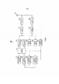
Portanto, um objetivo da presente invenção proporciona um aparelho de comunicação de rádio e um método de comunicação de rádio para tornar possível suprimir o aumento do overhead de sinalização e comutar corretamente os modos de transmissão de um PUSCH e um PUCCH, ao mesmo tempo.Therefore, an object of the present invention provides a radio communication apparatus and a radio communication method to make it possible to suppress the increase in signaling overhead and correctly switch the transmission modes of a PUSCH and a PUCCH at the same time.
Um aparelho de comunicação de rádio de acordo com a presente invenção emprega uma configuração que inclui: uma seção de determinação de relatório de informações de disparo que determina se deve- se relatar ou não as informações de disparo que induzem a comutação de um modo de transmissão de multiplexação por divisão de tempo e um mo- do de transmissão de multiplexação por divisão de frequência, que são métodos de multiplexação de um canal compartilhado e um canal de controle, em um aparelho de comunicação de terceiros; e uma seção de transmissão que transmite as informações de disparo para o aparelho de comunicação de terceiros, quando se determinar que as informações de disparo sejam transmitidas.A radio communication apparatus in accordance with the present invention employs a configuration including: a trigger information report determining section which determines whether or not to report the trigger information that induces switching of a transmission mode time division multiplexing and a frequency division multiplexing transmission mode, which are methods of multiplexing a shared channel and a control channel in a third party communication apparatus; and a transmission section which transmits the trigger information to the third party communication apparatus when the trigger information is determined to be transmitted.
Um aparelho de comunicação de rádio, de acordo com a presente invenção, emprega uma configuração que inclui: uma seção de detecção de informações de disparo que detecta informações de disparo que induzem a comutação de um modo de transmissão de multiplexação por divisão de tempo e um modo de transmissão de multiplexação por divisão de frequência, que são métodos de multiplexação de um canal compartilhado e um canal de controle, a partir de um sinal transmitido a partir de um aparelho de comunicação de terceiros; uma seção de controle de modo de transmissão que comuta um modo de transmissão a ser usado na próxima transmissão pelo aparelho de comunicação de terceiros, com base nas informações de disparo detectadas; e uma seção de transmissão que transmite as informações de ordem de modo de transmissão que ordenam a comutação do modo de transmissão, para o aparelho de comunicação de terceiros, ao comutar o modo de transmissão.A radio communication apparatus in accordance with the present invention employs an arrangement including: a trigger information detection section that detects trigger information that induces switching of a time division multiplexing transmission mode and a frequency division multiplexing transmission mode, which are methods of multiplexing a shared channel and a control channel from a signal transmitted from a third party communication apparatus; a transmission mode control section that switches a transmission mode to be used in the next transmission by the third party communication apparatus based on the detected trigger information; and a transmission section that transmits the transmission mode ordering information that orders the switching of the transmission mode, to the third party communication apparatus, by switching the transmission mode.
Um método de comunicação de rádio, de acordo com a presente invenção, emprega uma configuração que inclui os métodos de: determinar se deve-se relatar informações de disparo ou não que induzem a comutação de um modo de transmissão de multiplexação por divisão de tempo e um modo de transmissão de multiplexação por divisão de frequência, que são métodos de multiplexação de um canal compartilhado e um canal de controle, para um aparelho de comunicação de terceiros; e transmitir as informações de disparo para o aparelho de comunicação de terceiros, quando se determinar que as informações de disparo sejam transmitidas.A radio communication method in accordance with the present invention employs a configuration that includes the methods of: determining whether or not to report trigger information that induces switching of a time division multiplexing transmission mode and a frequency division multiplexing transmission mode, which are methods of multiplexing a shared channel and a control channel, to a third party communication apparatus; and transmitting the trigger information to the third party communication apparatus when the trigger information is determined to be transmitted.
Um método de comunicação de rádio, de acordo com a presente invenção, emprega uma configuração que inclui os métodos de: detectar informações de disparo que induzem a comutação de um modo de transmis são de multiplexação por divisão de tempo e um modo de transmissão de multiplexação por divisão de frequência, que são métodos de multiplexação de um canal compartilhado e um canal de controle, a partir de um sinal transmitido a partir de um aparelho de comunicação de terceiros; comutar um modo de transmissão a ser usado na próxima transmissão pelo aparelho de comunicação de terceiros, com base nas informações de disparo detectadas; e transmitir informações de ordem de modo de transmissão que ordenam a comutação do modo de transmissão, para o aparelho de comunicação de terceiros, ao comutar o modo de transmissão.A radio communication method in accordance with the present invention employs an embodiment including the methods of: detecting trigger information that induces switching of a time division multiplexing transmission mode and a multiplexing transmission mode frequency division, which are methods of multiplexing a shared channel and a control channel from a signal transmitted from a third party communication apparatus; switching a transmission mode to be used in the next transmission by the third party communication apparatus based on the detected trigger information; and transmitting transmission mode ordering information that orders the switching of the transmission mode, to the third party communication apparatus, by switching the transmission mode.
De acordo com a presente invenção, é possível suprimir o aumento do overhead de sinalização e comutar corretamente os modos de transmissão de um PUSCH e um PUCCH ao mesmo tempo.According to the present invention, it is possible to suppress the increase in signaling overhead and correctly switch the transmission modes of a PUSCH and a PUCCH at the same time.
A Figura 1 mostra uma condição em que um PUSCH e um PUCCH são transmitidos por TDM; a Figura 2 mostra uma condição em que um PUSCH e um PUCCH são transmitidos por FDM; a Figura 3 mostra a PHR que é determinada com base na energia de transmissão de um PUSCH como uma referência; a Figura 4 mostra uma condição em que o overhead de sinalização está aumentando; a Figura 5 é um diagrama de bloco que mostra uma configuração de uma estação móvel, de acordo com a modalidade 1 da presente invenção; a Figura 6 é um diagrama de bloco que mostra uma configuração interna da seção de geração de sinal TDM mostrada na Figura 5; a Figura 7 é um diagrama de bloco que mostra uma configuração interna da seção de geração de sinal FDM mostrada na Figura 5; a Figura 8 é um diagrama de bloco que mostra uma configuração de uma estação base de acordo com a modalidade 1 da presente invenção; a Figura 9 é um diagrama de bloco que mostra uma configuração interna da seção de demultiplexação de sinal TDM mostrada na Figura 8; a Figura 10 é um diagrama de bloco que mostra uma configuração interna da seção de demultiplexação de sinal FDM mostrada na Figura 8; a Figura 11 é um diagrama de sequência que mostra uma condição em que a estação móvel mostrada na Figura 5 transmite informações PHR_pusch e de disparo (PHR_pucch) para a estação base mostrada na Figura 8; a Figura 12 é um diagrama de sequência que mostra um caso em que as informações de disparo mostradas na Figura 11 são informações de indicador de um bit que mostra o resultado da comparação com um valor limítrofe; a Figura 13 é um diagrama de sequência que mostra uma condição em que informações PHRpusch e de disparo, que são informações de indicador de um bit, são relatadas; a Figura 14 é um diagrama de bloco que mostra a configuração de uma estação móvel de acordo com a modalidade 2 da presente invenção; a Figura 15 é um diagrama de sequência que mostra uma condição em que a estação móvel mostrada na Figura 14 transmite informações PHR pusch e de disparo (PHR_pucch) para a estação base mostrada na Figura 8; a Figura 16 é um diagrama de bloco que mostra a configuração de uma estação móvel de acordo com a modalidade 3 da presente invenção; e a Figura 17 é um diagrama de sequência que mostra uma condição em que a estação móvel mostrada na Figura 16 transmite informações PHR pusch e de disparo (PHR_pusch+pucch) para a estação base mostrada na Figura 8.Figure 1 shows a condition where a PUSCH and a PUCCH are transmitted by TDM; Figure 2 shows a condition where a PUSCH and a PUCCH are transmitted by FDM; Figure 3 shows the PHR which is determined based on the transmit power of a PUSCH as a reference; Figure 4 shows a condition where signaling overhead is increasing; Figure 5 is a block diagram showing a configuration of a mobile station according to embodiment 1 of the present invention; Figure 6 is a block diagram showing an internal configuration of the TDM signal generation section shown in Figure 5; Figure 7 is a block diagram showing an internal configuration of the FDM signal generation section shown in Figure 5; Figure 8 is a block diagram showing a configuration of a base station according to embodiment 1 of the present invention; Figure 9 is a block diagram showing an internal configuration of the TDM signal demultiplexing section shown in Figure 8; Figure 10 is a block diagram showing an internal configuration of the FDM signal demultiplexing section shown in Figure 8; Figure 11 is a sequence diagram showing a condition where the mobile station shown in Figure 5 transmits PHR_pusch and trigger (PHR_pucch) information to the base station shown in Figure 8; Figure 12 is a sequence diagram showing a case where the trigger information shown in Figure 11 is one-bit indicator information showing the result of comparing with a threshold value; Figure 13 is a sequence diagram showing a condition in which PHRpusch and trigger information, which is one-bit indicator information, is reported; Figure 14 is a block diagram showing the configuration of a mobile station according to embodiment 2 of the present invention; Figure 15 is a sequence diagram showing a condition where the mobile station shown in Figure 14 transmits PHR push and trigger information (PHR_pucch) to the base station shown in Figure 8; Figure 16 is a block diagram showing the configuration of a mobile station according to embodiment 3 of the present invention; and Figure 17 is a sequence diagram showing a condition where the mobile station shown in Figure 16 transmits PHR push and trigger information (PHR_pusch+pucch) to the base station shown in Figure 8.
Agora, as modalidades da presente invenção serão descritas em detalhes com referência aos desenhos em anexo. Nas modalidades, às mesmas partes serão atribuídas as mesmas referências numéricas e explicações sobrepostas serão omitidas.Now, embodiments of the present invention will be described in detail with reference to the accompanying drawings. In modalities, the same parts will be assigned the same numerical references and overlapping explanations will be omitted.
A Figura 5 mostra uma configuração de um aparelho de estação móvel de comunicação de rádio 100 (daqui por diante simplesmente referida como "estação móvel") de acordo com a modalidade 1 da presente invenção. Nesta Figura, a seção de recepção de RF 102 realiza o processamento de recepção, tal como, conversão descendente e conversão A/D, em um sinal recebido através da antena 101, e emite o sinal de recepção processado para a seção de demodulação 103.Figure 5 shows a configuration of a radio communication mobile station apparatus 100 (hereinafter simply referred to as "mobile station") in accordance with embodiment 1 of the present invention. In this Figure,
A seção de demodulação 103 demodula as informações de pro-gramação e um sinal piloto que são contidos no sinal de recepção emitido a partir da seção de recepção de RF 102, e emite as informações de programação demoduladas para a seção de cálculo de PHRdata 104, seção de cálculo de PHR_control 106 e seção de ajuste de modo de transmissão 107. Ademais, a seção de demodulação 103 emite o sinal piloto demodulado para a seção de cálculo de PHR data 104 e a seção de cálculo de PHR_control 106.The
A seção de cálculo de PHR_data 104 calcula a PHR_pusch (P- HR baseada em um PUSCH) ao realizar o cálculo da Equação 1 com base, por exemplo, em um nível de perda de percurso medido usando o sinal piloto de enlace descendente emitido a partir da seção de demodulação 103, o número de blocos de recurso de frequência de um PUSCH, o MCS, e informações de controle de um PUSCH que são contidas nas informações de programação emitidas a partir da seção de demodulação 103, e emite a PHR pusch calculada na seção de determinação de relatório de PHR data 105.The
A seção de determinação de relatório de PHR_data 105 determina se deve-se relatar ou não a PHR_pusch emitida a partir da seção de cálculo de PHR_data 104, para uma estação base, com base no ciclo T [ms] determinado antecipadamente pela estação base. Ou seja, no caso em que mais que T [ms] passou a partir do relatório anterior de PHR_pusch, PHR_pusch será relatada e, no caso em que mais que T [ms] não passou a partir do relatório anterior de PHR pusch, PHR pusch não será relatada. Mediante a determinação para relatar PHR pusch, a seção de determinação de relatório de PHR data 105 emite PHR_pusch para a seção de geração de dados 109.The report determination section of
A seção de cálculo de PHR_control 106 calcula PHR_pucch (PHR com base em um PUCCH) ao realizar o cálculo da Equação 3, com base, por exemplo, em um nível de perda de percurso medido usando o sinal piloto de enlace descendente emitido a partir da seção de demodulação 103, e informações de controle de energia de um PUCCH contido nas informações de programação emitidas a partir da seção de demodulação 103, e emite a PHR_pucch calculada para a seção de determinação de relatório de informações de disparo 108.The
A seção de ajuste de modo de transmissão 107 detecta um comando de um método de multiplexação de um PUSCH e um PUCCH (modo de transmissão TDM ou modo de transmissão FDM) que é contido nas informações de programação emitidas a partir da seção de demodulação 103, e emite o resultado de detecção para a seção de determinação de relatório de informações de disparo 108 e a seção de comutação 111.The transmission
A seção de determinação de relatório de informações de disparo 108 é comparada a uma das PHR_pucch emitidas a partir da seção de cálculo de PHR_control 106 e um valor limítrofe predeterminado é menor ou maior, isto é, a comparação com um valor limítrofe. A seção de determinação de relatório de informações de disparo 108 determina se deve-se relatar ou não as informações de disparo, com base no resultado da comparação com um valor limítrofe. Aqui, a condição de comparação com um valor limítrofe é alterada de acordo com o modo de transmissão emitido a partir da seção de ajuste de modo de transmissão 107. Aqui, as informações de disparo são informações de PHR pucch ou indicador que mostram se a P- HR_pucch é maior ou menor que um valor limítrofe. Como um resultado da comparação com um valor limítrofe, mediante a determinação para relatar as informações de disparo, a seção de determinação de relatório de informa ções de disparo 108 emite informações de disparo para a seção de geração de dados 109. A seção de determinação de relatório de informações de disparo 108 será posteriormente descrita.The trigger information
A seção de geração de dados 109 gera dados a serem transmitidos pela estação móvel 100. Ademais, mediante a recepção da PHR_pusch emitida a partir da seção de determinação de relatório de PHRdata 105, ou mediante a recepção de informações de PHR pusch ou disparo emitidas a partir da seção de determinação de relatório de informações de disparo 108, a seção de geração de dados 109 gera dados que incluem aquela PHR_pusch ou aquelas informações de disparo, e emite os dados gerados para a seção de comutação 111.The
A seção de geração de informações de controle 110 gera informações de controle (por exemplo, informações CQI, ACK ou NACK) a serem transmitidas pela estação móvel 100, e emite as informações de controle geradas para a seção de comutação 111.The control
A seção de comutação 111 comuta quer para transmitir por TDM ou transmitir por FDM os dados emitidos a partir da seção de geração de dados 109 e as informações de controle emitidas a partir da seção de geração de informações de controle 110, de acordo com o comando da seção de ajuste de modo de transmissão 107. Mediante a recepção de um comando do modo de transmissão TDM a partir da seção de ajuste de modo de transmissão 107, a seção de comutação 111 emite dados e as informações de controle para a seção de geração de sinal TDM 112. Por outro lado, mediante a recepção de um comando de transmissão FDM a partir da seção de ajuste de modo de transmissão 107, a seção de comutação 111 emite os dados e as informações de controle para a seção de geração de sinal FDM 113.The
A seção de geração de sinal TDM 112 gera um sinal TDM por tempo que multiplexa os dados e as informações de controle que são emitidos a partir da seção de comutação 111, e emite o sinal TDM para a seção de adição de CP 114. A seção de geração de sinal TDM 112 será descrita posteriormente em detalhes.The TDM
A seção de geração de sinal FDM 113 gera um sinal FDM por frequência que multiplexa os dados e as informações de controle que são emitidos a partir da seção de comutação 111, e emite o sinal FDM para a seção de adição de CP 114. A seção de geração de sinal FDM 113 será posteriormente descrita em detalhes.The FDM
A seção de adição de CP 114 copia parte da extremidade traseira do sinal emitido a partir da seção de geração de sinal TDM 112 ou seção de geração de sinal FDM 113, como um CP, e adiciona o CP na frente deste sinal. O sinal adicionado por CP é emitido para a seção de transmissão de RF 115.
A seção de transmissão de RF 115 realiza o processamento de transmissão, tal como, a conversão D/A, amplificação e conversão ascendente, no sinal emitido a partir da seção de adição de CP 114, e transmite o sinal processado por transmissão para uma estação base a partir da antena 101.The
A Figura 6 é um diagrama de bloco que mostra uma configuração interna da seção de geração de sinal TDM 112 mostrada na Figura 5. Nesta Figura, a seção de multiplexação 121 multiplexa os dados e as informações de controle que são emitidos a partir da seção de comutação 111 no domínio de tempo, isto é, TDM multiplexa, e emite sinal multiplexado por TDM para a seção transformada de fourier discreta (DFT) 122.Figure 6 is a block diagram showing an internal configuration of the TDM
A seção de DFT 122 realiza o processamento DFT no sinal mul-tiplexado emitido a partir da seção de multiplexação 121 e emite o sinal mul-tiplexado processado por DFT para a seção de mapeamento 123.The
A seção de mapeamento 123 mapeia o sinal emitido a partir da seção de DFT 122 na banda de frequência programada por uma estação base, e emite o sinal mapeado para a seção de transformada de fourier discreta inversa (IDFT) 124.The
A seção de IDFT 124 realiza o processamento IDFT no sinal de domínio de frequência emitido a partir da seção de mapeamento 123, converte o sinal em um sinal de domínio de tempo e emite o sinal de domínio de tempo para a seção de adição de CP 114.The
A Figura 7 é um diagrama de bloco que mostra uma configuração interna da seção de geração de sinal FDM 113 mostrada na Figura 5. Nesta Figura, a seção de DFT 131 realiza o processamento DFT nos dados emitidos a partir da seção de comutação 111 e emite os dados processados por DFT para a seção de mapeamento 132.Figure 7 is a block diagram showing an internal configuration of the FDM
A seção de mapeamento 132 mapeia o sinal de dados emitido a partir da seção de DFT 131 e as informações de controle emitidas a partir da seção de comutação 111 na banda de frequência programada pela estação base, multiplexa o sinal de dados mapeado e as informações de controle no domínio de frequência, isto é, FDM multiplexa e emite o sinal multiplexado por FDM para a seção de IDFT 133.The
A seção de IDFT 133 realiza IDFT o processamento no sinal de domínio de frequência emitido a partir da seção de mapeamento 132, converte o sinal em um sinal de domínio de tempo, e emite o sinal de domínio de tempo para a seção de adição de CP 114.The
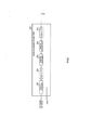
A Figura 8 é um diagrama de bloco que mostra uma configuração do aparelho de estação base de comunicação de rádio 200 (daqui por diante simplesmente referido como "estação base") de acordo com a modalidade 1 da presente invenção. Nesta Figura, a seção de recepção de RF 202 recebe um sinal transmitido a partir da estação móvel 100 através da antena 201, realiza o processamento de recepção, tal como, a conversão descendente e a conversão A/D, no sinal recebido, e emite o sinal de recepção processado para a seção de remoção de CP 203.Figure 8 is a block diagram showing a configuration of radio communication base station apparatus 200 (hereinafter simply referred to as "base station") in accordance with embodiment 1 of the present invention. In this Figure, the
A seção de remoção de CP 203 remove o CP do sinal emitido a partir da seção de recepção de RF 202 e emite o sinal sem um CP para a seção de comutação 204.The
A seção de comutação 204 comuta quer para demultiplexer os dados e as informações de controle no domínio de tempo ou demultiplexer os dados e as informações de controle no domínio de frequência, de acordo com o modo de transmissão relatado para a estação móvel 100. Ao relatar um comando do modo de transmissão TDM para a estação móvel 100, a seção de comutação 204 emite o sinal sem um CP para a seção de demulti- plexação de sinal TDM 205, e ao relatar um comando do modo de transmissão FDM para a estação móvel 100, a seção de comutação 204 emite o sinal sem um CP para a seção de demultiplexação de sinal FDM 206.The
A seção de demultiplexação de sinal TDM 205 demultiplexa os dados e as informações de controle no domínio de tempo, e emite as informações de controle demultiplexadas para a seção de decodificação de informações de controle 207 e emite os dados demultiplexados para a seção de decodificação de dados 208. A seção de demultiplexação de sinal TDM 205 será posteriormente descrita em detalhes.The TDM
A seção de demultiplexação de sinal FDM 206 demultiplexa os dados e as informações de controle no domínio de frequência, e emite as informações de controle demultiplexadas para a seção de decodificação de informações de controle 207 e emite os dados demultiplexados para a seção de decodificação de dados 208. A seção de demultiplexação de sinal FDM 206 será posteriormente descrita em detalhes.The FDM
A seção de decodificação de informações de controle 207 decodifica as informações de controle emitidas a partir da seção de demultiplexação de sinal TDM 205 ou seção de demultiplexação de sinal FDM 206 para obter as informações de controle transmitidas a partir da estação móvel 100.The control
A seção de decodificação de dados 208 decodifica os dados e- mitidos a partir da seção de demultiplexação de sinal TDM 205 ou seção de demultiplexação de sinal FDM 206, e emite os dados decodificados para a seção de detecção de informações de disparo 209.The
A seção de detecção de informações de disparo 209 detecta in-formações de disparo contidas nos dados emitidos a partir da seção de de-codificação de dados 208, e emite as informações de disparo detectadas para a seção de controle de modo de transmissão 210.The trigger
A seção de controle de modo de transmissão 210 determina comutar o método de multiplexação dos dados data (PUSCH) e das informações de controle (PUCCH) que serão transmitidos a partir da estação móvel 100, que usa as informações de disparo emitidas a partir da seção de detecção de informações de disparo 209. Mediante a alteração do modo de transmissão anterior, a seção de controle de modo de transmissão 210 emite informações de ordem de modo de transmissão para a seção de comutação 204 e a seção de modulação 211. A seção de controle de modo de transmissão 210 será posteriormente descrita em detalhes.The transmission
A seção de modulação 211 modula as informações de ordem de modo de transmissão emitidas a partir da seção de controle de modo de transmissão 210, e emite o sinal modulado para a seção de transmissão de RF 212.The
A seção de transmissão de RF 212 realiza o processamento de transmissão, tal como, a conversão D/A, amplificação e conversão ascendente no sinal modulado emitido a partir da seção de modulação 211, e transmite o processado por transmissão para a estação móvel a partir da antena 201.The
A Figura 9 é um diagrama de bloco que mostra uma configuração interna da seção de demultiplexação de sinal TDM 205 mostrada na Figura 8. Nesta Figura, a seção de DFT 221 realiza o processamento DFT no sinal de recepção sem um CP que é emitido a partir da seção de comutação 204, e emite o sinal convertido a partir do domínio de tempo para o domínio de frequência, na seção de desmapeamento 222.Figure 9 is a block diagram showing an internal configuration of the TDM
A seção de desmapeamento 222 extrai um sinal de recepção da estação móvel desejada 100 a partir da banda de frequência programada pela estação base 200, fora dos sinais de domínio de frequência emitidos a partir da seção de DFT 221, e emite o sinal de recepção extraído para a seção de equalização 223.The
A seção de equalização 223 calcula um valor de estimativa de canal a partir de um sinal piloto contido no sinal de recepção emitido a partir da seção de desmapeamento 222. A seção de equalização 223 realiza o processamento de equalização para corrigir alterações da amplitude e da fase no domínio de frequência que o sinal de recepção emite a partir da seção de desmapeamento 222 recebido no canal, usando o valor de estimativa de canal, e emite o sinal de recepção após o processamento de equalização para a seção de IDFT 224.
A seção de IDFT 224 realiza o processamento IDFT no sinal de recepção emitido a partir da seção de equalização 223, converte o sinal de recepção processado por IDFT em um sinal de domínio de tempo, e emite o sinal de domínio de tempo para a seção de demultiplexação 225.The
A seção de demultiplexação 225 demultiplexa o sinal de recepção emitido a partir da seção de IDFT 224 para as informações de controle e dados no domínio de tempo, e emite o sinal de controle demultiplexado para a seção de decodificação de informações de controle 207 e emite os dados demultiplexados para a seção de decodificação de dados 208.The
A Figura 10 é um diagrama de bloco que mostra uma configuração interna da seção de demultiplexação de sinal FDM 206 mostrada na Figura 8. Nesta Figura, a seção de DFT 231 realiza o processamento DFT no sinal de recepção sem um CP que é emitido a partir da seção de comutação 204, e emite o sinal convertido a partir do domínio de tempo para o domínio de frequência, na seção de desmapeamento 232.Figure 10 is a block diagram showing an internal configuration of the FDM
A Seção de desmapeamento 232 extrai os dados e as informações de controle de um sinal de recepção da estação móvel desejada 100 a partir da banda de frequência programada pela estação base 200, fora dos sinais de domínio de frequência emitidos a partir da seção de DFT 231, e emite os dados extraídos para a primeira seção de equalização 233 e emite as informações de controle extraídas para a segunda seção de equalização 234.The
A primeira seção de equalização 233 calcula um valor de estimativa de canal a partir de um sinal piloto contido no sinal de recepção emitido a partir da seção de desmapeamento 232. A primeira seção de equalização 233 realiza o processamento de equalização para corrigir as alterações da amplitude e da fase no domínio de frequência que as informações de controle emitidas a partir da seção de desmapeamento 232 receberam no canal que usa o valor de estimativa de canal, e emite as informações de controle obtidas para a seção de decodificação de informações de controle 207.The
A segunda seção de equalização 234 calcula um valor de estimativa de canal a partir de um sinal piloto contido no sinal de recepção emi tido a partir da seção de desmapeamento 232. A segunda seção de equali- zação 234 realiza o processamento de equalização para corrigir alterações da amplitude e da fase no domínio de frequência que os dados emitidos a partir da seção de desmapeamento 232 receberam no canal, usando o valor de estimativa de canal, e emite os dados obtidos para a seção de IDFT 235.The
A seção de IDFT 235 realiza o processamento IDFT nos dados emitidos a partir da segunda seção de equalização 234, converte os dados processados por IDFT em um sinal de domínio de tempo, e emite o sinal de domínio de tempo para a seção de decodificação de dados 208.The
A seguir, a seção de determinação de relatório de informações de disparo 108 mostrada na Figura 5 será descrita em detalhes abaixo. A seção de determinação de relatório de informações de disparo 108 realiza a comparação com um valor limítrofe em relação à PHR_pucch da estação móvel 100 que é calculada pela estação móvel 100, para determinar se deve relatar ou não as informações de disparo.Next, the trigger information
De maneira específica, no modo de transmissão TDM, as informações de disparo são relatadas quando a Equação 5 for satisfeita. X1 é a energia de transmissão requerida para um PUSCH que tem o maior MCS (qualidade requerida mais alta), por exemplo, na largura de banda de transmissão máxima assumida. Esta é antecipadamente ajustada na estação móvel 100 pela estação base 200. Isto significa que, quando a Equação 5 for satisfeita, mesmo quando um PUSCH e um PUCCH forem transmitidos por FDM, é possível evitar que a energia de transmissão da estação móvel 100 exceda a energia de transmissão máxima (Pjnax).
Ademais, no modo de transmissão FDM, as informações de disparo são relatadas quando a Equação 6 for satisfeita. Y1 é ajustado como o mesmo valor que X1, por exemplo. Isto significa que, quando a Equação 6 for satisfeita, mesmo quando um PUSCH e um PUCCH forem transmitidos por FDM, é possível evitar que a energia de transmissão da estação móvel 100 exceda a energia de transmissão máxima (P_max).
Ademais, é possível ajustar Y1 como um valor diferente de X1. Quando Y1 e X1 tiverem o mesmo valor, relatórios de informações de disparo ocorrem frequentemente na estação móvel 100 que tem a PHRpucch que se move para cima e para baixo ao redor do valor limítrofe. Efetuando- se uma diferença entre Y1 e X1, é possível evitar os relatórios frequentes de informações de disparo descritos acima.Furthermore, it is possible to set Y1 as a value other than X1. When Y1 and X1 have the same value, trigger information reports often occur in the
Ademais, a informação de disparo a ser relatada podem ser a própria PHR_pucch, ou informações de indicador de um bit que mostra se a PHR pucch é maior ou menor que um valor limítrofe. No caso em que P- HR_pucch for ajustada como as informações de disparo, embora a quantidade de sinalização aumente, ao relatar PHR_pucch corretamente, a estação base 200 pode comutar o modo de transmissão more corretamente e controlar a largura de banda de transmissão e o MCS de um PUSCH. Por outro lado, no caso em que as informações de indicador de um bit são ajustadas como informações de disparo, embora o controle de comutação do modo de transmissão se torne menos preciso, é possível reduzir o overhead de sinalização. Aqui, ao controlar a largura de banda de transmissão e MCS de um PUSCH dentro da faixa assumida mediante o ajuste de X1 ou Y1, é possível evitar que a energia de transmissão de uma estação móvel exceda a energia de transmissão máxima, mesmo após a comutação do modo de transmissão.Furthermore, the trigger information to be reported can be the PHR_pucch itself, or one-bit indicator information that shows whether the PHR pucch is greater or less than a threshold value. In the case where P-HR_pucch is set as the trigger information, although the amount of signaling increases, by reporting PHR_pucch correctly, the
A seguir, a seção de controle de modo de transmissão 210 mostrada na Figura 8 será descrita em detalhes. A seção de controle de modo de transmissão 210 determina a comutação dos dados de método de multiplexação (PUSCH) e informações de controle (PUCCH) que serão transmitidos da próxima vez pela estação móvel 100, usando as informações de disparo relatadas a partir da estação móvel 100.Next, the transmission
De maneira específica, no caso em que a estação móvel 100 se encontra no modo de transmissão TDM, quando a estação base 200 obtém informações de disparo relatadas a partir da estação móvel 100 ao satisfazer a Equação 5, a seção de controle de modo de transmissão 210 comuta a propriadamente o modo de transmissão da estação móvel 100 a partir do modo de transmissão TDM para o modo de transmissão FDM. Na condição em que a estação base 100 relata as informações de disparo no modo de transmissão TDM, mesmo quando o modo de transmissão for comutado para o modo de transmissão FDM, é possível evitar que a energia de transmissão da estação móvel 100 exceda a energia de transmissão máxima (P_max).Specifically, in the case where the
Ademais, no caso em que a estação móvel 100 se encontra no modo de transmissão FDM, quando a estação base 200 obtém informações de disparo relatadas a partir da estação móvel 100 ao satisfazer a Equação 6, a seção de controle de modo de transmissão 210 comuta apropriadamente o modo de transmissão da estação móvel 100 a partir do modo de transmissão FDM para o modo de transmissão TDM. Na condição em que a estação móvel 100 relata informações de disparo no modo de transmissão FDM, ao comutar o modo de transmissão para o modo de transmissão TDM, é possível evitar que a energia de transmissão da estação móvel 100 exceda a energia de transmissão máxima (Pmax).Furthermore, in the case where
A seguir, o ciclo no qual a estação móvel 100 relata PHR pusch, será descrito abaixo. Primeiro, devido ao fato de os usos de PHR pusch e PHR pucch serem diferentes, ao relatar PHR pusch ou PHR_pucch de a- cordo com a frequência e precisão que corresponde ao uso, é possível suprimir o aumento de overhead de sinalização e comutar apropriadamente o modo de transmissão ao mesmo tempo.Next, the cycle in which
Como o uso de PHR_pusch, PHR_pusch é usada para controlar a largura de banda de transmissão e o MCS de um PUSCH de modo que a energia de transmissão não exceda a energia de transmissão máxima da estação móvel 100. Por outro lado, como o uso de PHR pucch, P- HR_pucch é usada para determinar a comutação no modo de transmissão (modo de transmissão TDM ou modo de transmissão FDM). Devido ao fato de a largura de banda de transmissão e o MCS de um PUCCH serem fixos, não é necessário controlar a banda de transmissão e o MCS diferente de um PUSCH.Like the use of PHR_pusch, PHR_pusch is used to control the transmission bandwidth and MCS of a PUSCH so that the transmission power does not exceed the maximum transmission power of the
Portanto, não é necessário relatar a PHR pucch que é usada para comutar o modo de transmissão tão frequente e precisamente quanto PHR pusch. Apenas quando a estação móvel 100 pode comutar o modo de transmissão ou precisa comutar o modo de transmissão, a estação base 200 pode comutar o modo de transmissão apropriadamente ao relatar a P- HR pucch para a estação base 200.Therefore, it is not necessary to report the PHR pucch which is used to switch the transmission mode as frequently and accurately as PHR pusch. Only when
A Figura 11 é um diagrama de sequência que mostra uma condição em que a estação móvel 100 mostrada na Figura 5 transmite informações de PHR_pusch e de disparo (PHR_pucch) para a estação base 200 mostrada na Figura 8. A estação base 200 pode conhecer informações sobre a PHR_pucch da estação móvel 100 a partir das informações de disparo, de modo que, no modo de transmissão TDM, a energia de transmissão da estação móvel 100 não exceda a energia máxima, tornado possível comutar o modo de transmissão para o modo de transmissão FDM apropriadamente. Ademais, no modo de transmissão FDM, é possível comutar o modo de transmissão para o modo de transmissão TDM apropriadamente, antes que a energia de transmissão da estação móvel 100 exceda a energia máxima. Comparado à Figura 4, fica claro que o aumento do overhead de sinalização é suprimido. Conforme descrito acima, ao relatar informações de disparo apenas quando for possível ou necessário comutar o modo de transmissão, é possível suprimir o aumento de overhead de sinalização.Figure 11 is a sequence diagram showing a condition where the
Ademais, a Figura 12 é um diagrama de sequência que mostra um caso em que as informações de disparo mostradas na Figura 11 são informações de indicador de um bit que mostra o resultado da comparação com um valor limítrofe. Conforme mostrado nesta Figura, ao ajustar as informações de disparo como informações de indicador de um bit que mostra o resultado da comparação com um valor limítrofe, embora o controle de comutação do modo de transmissão se torne menos preciso comparado ao caso em que a informação de disparo é PHR pucch, é possível suprimir adicionalmente o aumento do overhead de sinalização.Furthermore, Fig. 12 is a sequence diagram showing a case where the trigger information shown in Fig. 11 is one-bit indicator information showing the result of comparing with a threshold value. As shown in this Figure, by setting the trigger information as one-bit indicator information that shows the result of comparing with a threshold value, although the transmission mode switching control becomes less accurate compared to the case where the transmission mode information trigger is PHR pucch, it is possible to additionally suppress the increase in signaling overhead.
Conforme descrito acima, de acordo com a modalidade 1, ao realizar a comparação com um valor limítrofe ao alterar a condição da compa- ração com um valor limítrofe de PHR pucch de uma estação móvel, de a- cordo com o modo de transmissão TDM ou o modo de transmissão FDM, que são métodos de multiplexação de um PUSCH e um PUCCH adotado pela estação móvel, e relatar informações de disparo que induzem a comutação entre o modo de transmissão TDM e o modo de transmissão FDM a partir da estação móvel para uma estação base de acordo com o resultado da comparação com um valor Hmrtrofe, é possível suprimir o aumento do overhead de sinalização e comutar corretamente o modo de transmissão.As described above, according to modality 1, when performing the comparison with a threshold value by changing the condition of the comparison with a threshold value of PHR pucch of a mobile station, according to the transmission mode TDM or the FDM transmission mode, which are methods of multiplexing one PUSCH and one PUCCH adopted by the mobile station, and reporting trigger information that induce switching between the TDM transmission mode and the FDM transmission mode from the mobile station to a base station according to the result of the comparison with an Hmrtrofe value, it is possible to suppress the increase in signaling overhead and correctly switch the transmission mode.
Aqui, nas expressões condicionais da Equação 5 e da Equação 6, é possível usar PHR_pucch+pucch (PHR calculada com base na energia de transmissão requerida quando um canal de dados e u m canal de controle forem transmitidos por FDM, como uma referência) definida na seguinte Equação 7, em vez de PHR pucch.
Devido ao fato de que é possível estimar PHR_pucch a partir de duas partes de informações PHR de PHR_pusch+pucch e PHR_pusch, é possível obter um efeito equivalente ao caso de relatório de PHR_pucch.Due to the fact that it is possible to estimate PHR_pucch from the two pieces of PHR information of PHR_pusch+pucch and PHR_pusch, it is possible to obtain an effect equivalent to the reporting case of PHR_pucch.
Aqui, no caso de usar PHR pusch+pucch, é necessário usar um valor limítrofe diferente dos valores limítrofes da Equação 5 e da Equação 6 que usam PHR_pucch. Ou seja, no modo de transmissão TDM, a comparação com um valor limítrofe é realizada com base na seguinte Equação 8, e no modo de transmissão FDM, a comparação com um valor limítrofe é realizada com base na seguinte Equação 9.
Embora seja possível ajustar o mesmo valor para X2 e Y2, ao ajustar uma diferença entre X2 e Y2 para ajustar valores diferentes, como no caso da relação descrita acima entre X1 e Y1, uma estação móvel que tem a PHR_pusch+pucch que se move para cima e para baixo ao redor do valor limítrofe pode evitar relatórios frequentes de informações de disparo.Although it is possible to adjust the same value for X2 and Y2, by adjusting a difference between X2 and Y2 to adjust different values, as in the case of the relationship described above between X1 and Y1, a mobile station that has the PHR_pusch+pucch that moves to up and down around the threshold value can avoid frequent reporting of trigger information.
Conforme mostrado no diagrama de sequência da Figura 13, referindo-se à condição em que a seção de determinação de relatório de informações de disparo 108 relata as informações de disparo, é possível ajustar as informações de disparo à emissão como informações de indicador de um bit que mostra o resultado de comparação com um valor limítrofe, como no caso da PHR_pusch convencional. Comparado à Figura 4, fica claro que o aumento do overhead de sinalização é suprimido. Ademais, devido ao número de bits de sinalização ser constantemente igual (constantemente sete bits na Figura), é possível usar um formato de transmissão de sinalização, tornando possível simplificar o processamento de uma estação móvel e uma estação base.As shown in the sequence diagram of Figure 13, referring to the condition where the trigger information
A Figura 14 é um diagrama de bloco que mostra uma configuração da estação móvel 300 de acordo com a modalidade 2 da presente invenção. A Figura 14 difere da Figura 5 pelo fato de que a seção de ajuste de ciclo de relatório 301 é adicionada, a seção de determinação de relatório de PHR data 105 é alterada para a seção de determinação de relatório de P- HR_data 302, e a seção de determinação de relatório de informações de disparo 108 é alterada para a seção de determinação de relatório de informações de disparo 303.Figure 14 is a block diagram showing a configuration of
A seção de ajuste de ciclo de relatório 301 ajusta um ciclo de relatório de PHR_pusch e um ciclo de relatório de informações de disparo de modo que o ciclo de relatório de informações de disparo seja mais longo que o ciclo de relatório de PHR_pusch, e emite o ciclo de relatório ajustado da PHR pusch para a seção de determinação de relatório de PHRdata 302 e emite o ciclo de relatório de informações de disparo para a seção de determinação de relatório de informações de disparo 303.The reporting
A seção de determinação de relatório de PHR data 302 emite PHR pusch para a seção de geração de dados 109, no ciclo emitido a partir da seção de ajuste de ciclo de relatório 301.The report determination section of
A seção de determinação de relatório de informações de disparo 303 emite informações de disparo para a seção de geração de dados 109, no ciclo emitido a partir da seção de ajuste de ciclo de relatório 301.The trigger information
Aqui, a razão na qual a seção de ajuste de ciclo de relatório 301 ajusta o ciclo de relatório de informações de disparo (PHR_pucch) mais longo que o ciclo de relatório de PHR_pusch, será descrita abaixo. As informações de disparo (PHR pucch) usadas para comutar do modo de transmissão não precisam ser relatadas de maneira tão frequente e precisa quanto a PHR pusch usada para o controle sintonizado fino, tal como, adaptação de link, de modo que o ciclo de relatório de informações de disparo seja ajustado mais longo que o ciclo de relatório de PHR pusch.Here, the reason why the reporting
Por exemplo, no caso em que o ciclo de relatório de PHR_pusch for T [ms], o ciclo de relatório de informações de disparo é ajustado como NxT [ms] (aqui, N é um número natural). N é um parâmetro ajustado por célula ou por estação móvel, e é relatado a partir da estação base 200 para a estação móvel 300.For example, in the case where the reporting cycle of PHR_pusch is T [ms], the trigger information reporting cycle is set to NxT [ms] (here, N is a natural number). N is a cell or mobile station adjusted parameter, and is reported from
Os métodos de ajuste N incluem o seguinte método. Em uma célula que tem um raio de célula grande, devido ao fato e a perda de percurso aumentar, a PHR da estação móvel 300 localizada na borda de célula é pequena, de modo que é necessário comutar o modo de transmissão. Por outro lado, em uma célula que tem um raio de célula pequeno, é raro a estação móvel 300 precisar comutar o modo de transmissão. Portanto, ao ajustar N maior para uma célula com um raio de célula menor a fim de ajustar o ciclo de relatório de PHR_pucch mais longo, é possível comutar o modo de transmissão apropriadamente com uma pequena quantidade de sinalização.N adjustment methods include the following method. In a cell that has a large cell radius, due to the fact that the path loss increases, the PHR of the
A Figura 15 é um diagrama de sequência que mostra uma condição em que a estação móvel 300 mostrada na Figura 14 transmite informações PHR pusch e de disparo (PHR pucch) para a estação base 200 mostrada na Figura 8. À medida que é claro a partir da Figura 15, devido ao fato de as informações de disparo (PHR_pucch) serem relatadas em um ciclo longo, é possível suprimir o aumento de overhead de sinalização.Figure 15 is a sequence diagram showing a condition where the
Conforme descrito acima, de acordo com a modalidade 2, ao a- justar o ciclo de relatório de informações de disparo (PHR_pucch) mais longo que o ciclo de relatório de PHR_pusch, as informações de disparo (P- HR_pucch) são relatadas em um ciclo longo, tornando possível suprimir o aumento de overhead de sinalização.As described above, according to mode 2, when setting the trigger information reporting cycle (PHR_pucch) longer than the PHR_pusch reporting cycle, the trigger information (P-HR_pucch) is reported in one cycle long, making it possible to suppress the increase in signaling overhead.
A Figura 16 é um diagrama de bloco que mostra uma configuração da estação móvel 400 de acordo com a modalidade 3 da presente invenção. A Figura 16 difere da Figura 5 pelo fato de que a seção de cálculo de PHRcontrol 106 é alterada para a seção de cálculo de PHRcontrol 401, a seção de ajuste de modo de transmissão 107 é alterada para a seção de ajuste de modo de transmissão 402, a seção de determinação de relatório de PHR_data 105 é alterada para a seção de determinação de relatório de PHR_data 403, e a seção de determinação de relatório de informações de disparo 108 é alterada para a seção de determinação de relatório de informações de disparo 404.Figure 16 is a block diagram showing a configuration of
A seção de cálculo de PHRcontrol 401 calcula P- HR pusch+pucch (PHR calculada com base na energia de transmissão requerida quando um canal de dados e um canal de controle forem transmitidos por FDM, como uma referência) e PHR_pucch, com base em um nível de perda de percurso medido usando um sinal piloto de enlace descendente emitido a partir da seção de demodulação 103, e o número de blocos de recurso de frequência de um PUSCH, o MCS, as informações de controle de energia de um PUSCH e as informações de controle de energia de um PUCCH que são contidos nas informações de programação emitidas a partir da seção de demodulação 103, e emite a PHR_pusch+pucch e PHR_pucch calculada para a seção de determinação de relatório de informações de disparo 404.The calculation section of
A seção de ajuste de modo de transmissão 402 detecta um comando de um método de multiplexação de um PUSCH e um PUCCH (modo de transmissão TDM ou modo de transmissão FDM) que é contido nas informações de programação emitidas a partir da seção de demodulação 103, e emite o resultado da determinação para a seção de determinação de relatório de informações de disparo 404, seção de comutação 111 e seção de determinação de relatório de PHR_data 403.The transmission
No caso em que a estação móvel 400 se encontra no modo de transmissão FDM, a seção de determinação de relatório de PHR_data 403 não relata PHR_pusch. Por outro lado, a estação móvel 400 se encontra no modo de transmissão TDM, a seção de determinação de relatório de P- HR_data 403 relata a PHR_pusch emitida a partir da seção de cálculo de PHR_data 104 para a estação base 200, com base no ciclo predeterminado T [ms] determinado antecipadamente pela estação base 200.In the case where the
No caso em que a estação móvel 400 se encontra no modo de transmissão FDM, a seção de determinação de relatório de informações de disparo 404 determina o relatório da PHR pusch+pucch emitida a partir da seção de cálculo de PHRcontrol 401, com base no ciclo T [ms] determinado antecipadamente pela estação base 200. No caso em que a estação móvel 400 se encontra no modo de transmissão TDM, do mesmo modo que na modalidade 1, a seção de determinação de relatório de informações de disparo 404 realiza a comparação com um valor limítrofe ao comparar a P- HR pucch emitida a partir da seção de cálculo de PHR control 401 a um valor limítrofe predeterminado e, com base no resultado da comparação com o valor limítrofe, determina se deve relatar as informações de disparo ou não.In case the
Conforme descrito acima, no modo de transmissão FDM, a seção de determinação de relatório de PHR data 403 para a emissão da P- HR_pusch, e a seção de determinação de relatório de informações de disparo 404 relata a PHR_pusch+pucch como informações de disparo.As described above, in FDM transmission mode, the PHR report determination section dates 403 for the issuance of P-HR_pusch, and the trigger information
No modo de transmissão FDM, se o estação base 200 puder conhecer PHRpusch+pucch, a estação base 200 pode conhecer a quantidade de energia de transmissão da estação móvel 400 que pode ser aumentada, de modo que seja possível controlar a largura de banda de transmissão e o MCS de um PUSCH. Ademais, no caso em que a PHR pusch+pucch se torna menor (a margem de energia de transmissão é reduzida), ao alterar o modo de transmissão para o modo de transmissão TDM, é possível controlar a energia de transmissão da estação móvel 400 a fim de não exceder a e- nergia de transmissão máxima.In FDM transmission mode, if
Deste modo, no modo de transmissão FDM, quando uma estação base puder conhecer PHR_pusch+pucch, é possível controlar a comutação do modo de transmissão, e controlar a largura de banda de transmissão e o MCS de um PUSCH.Thus, in FDM transmission mode, when a base station can know PHR_pusch+pucch, it is possible to control transmission mode switching, and control transmission bandwidth and MCS of a PUSCH.
A Figura 17 é um diagrama de sequência que mostra uma condição em que a estação móvel 400 mostrada na Figura 16 transmite informações PHR_pusch e de disparo (PHR pusch+pucch) para a estação base 200 mostrada na Figura 8. À medida que se torna claro a partir da Figura 17, no modo de transmissão FDM, ao interromper o relatório de PHR_pusch, é possível suprimir o aumento do overhead de sinalização.Figure 17 is a sequence diagram showing a condition where
Conforme descrito acima, de acordo com a modalidade 3, no modo de transmissão FDM, ao relatar PHR_pusch+pucch como informações de disparo, uma estação móvel pode suprimir o aumento do overhead de sinalização.As described above, according to mode 3, in FDM transmission mode, by reporting PHR_pusch+pucch as trigger information, a mobile station can suppress increased signaling overhead.
No caso em que a faixa variável da PHR a ser relatada para PHR pusch+pucch for mais estreita comparada à PHR pusch, é possível reduzir o número de bits de sinalização de PHR_pusch+pucch. Por exemplo, quando a faixa variável de PHR for metade, é possível reduzir o número de bits de sinalização de seis para três. Isto significa que é possível suprimir adicionalmente o aumento do overhead de sinalização.In case where the variable range of PHR to be reported for PHR pusch+pucch is narrower compared to PHR pucch, it is possible to reduce the number of signaling bits of PHR_pusch+pucch. For example, when the PHR variable range is half, it is possible to reduce the number of signaling bits from six to three. This means that it is possible to additionally suppress the increase in signaling overhead.
Por outro lado, quando os números de bits de sinalização de PHR pusch+pucch e PHR_pusch forem ajustados iguais, é possível usar um formato de transmissão de sinalização. Isto significa que é possível sim- plificar o processamento de uma estação móvel ou uma estação base.On the other hand, when the numbers of signaling bits of PHR push+pucch and PHR_pusch are set equal, it is possible to use a signaling transmission format. This means that it is possible to simplify the processing of a mobile station or a base station.
No caso do cálculo de PHRpusch+pucch, é possível realizar o cálculo adicionando-se a quantidade de aumento de CM (=ΔCM) da transmissão FDM em relação à transmissão TDM, conforme mostrado na Equação 10 a seguir. Isto significa que é possível calcular PHR pusch+pucch de maneira mais precisa.
Ademais, em vez de relatar PHR_pucch ou PHR pusch+pucch, é possível relatar um valor relativo em relação à PHR_pusch que é relatada de maneira convencional. Isto significa que, é possível reduzir adicionalmente a quantidade de sinalização.Furthermore, instead of reporting PHR_pucch or PHR pusch+pucch, it is possible to report a relative value in relation to the PHR_pusch that is reported in the conventional way. This means that it is possible to further reduce the amount of signaling.
Ademais, do mesmo modo que PHR pusch na LTE, no caso em que PHR_pucch é relatada como informações MAC de um PUSCH, é possível calcular PHR_pucch com base na energia de transmissão no momento da transmissão de um PUCCH no tempo mais próximo.Furthermore, in the same way as PHR pucch in LTE, in the case where PHR_pucch is reported as MAC information of a PUSCH, it is possible to calculate PHR_pucch based on the transmission energy at the time of transmission of a PUCCH in the nearest time.
Ademais, em vez da PHR_pucch a ser recentemente relatada, é possível relatar as informações que podem derivar da PHR pucch (por e- xemplo, g(Δj) da Equação 4 (valor de controle de energia de transmissão para o qual o controle de circuito fechado é realizado) ou perda de percurso (PL)).Furthermore, instead of the PHR_pucch to be recently reported, it is possible to report the information that can be derived from the PHR pucch (for example, g(Δj) of Equation 4 (transmission power control value for which the circuit control closed is performed) or lost path (PL)).
Também, embora casos tenham sido descritos na modalidade acima como exemplos onde a presente invenção é configurada por hardware, a presente invenção também pode ser realizada por software.Also, although cases have been described in the above embodiment as examples where the present invention is configured by hardware, the present invention can also be performed by software.
Cada bloco de função empregado na descrição de cada uma das modalidades mencionadas acima pode ser tipicamente implementado como uma LSI constituída por um circuito integrado. Estes podem ser chips individuais ou parciais ou totalmente contidos em um único chip. A "LSI" é adotada aqui, porém, esta também pode ser referida como "IC", "sistema LSI", "super LSI" ou "ultra LSI" dependendo das diferentes extensões de integração.Each function block employed in the description of each of the above mentioned modalities can typically be implemented as an LSI consisting of an integrated circuit. These can be individual or partial chips or fully contained in a single chip. "LSI" is adopted here, however this may also be referred to as "IC", "LSI system", "super LSI" or "ultra LSI" depending on the different integration extensions.
Ademais, o método de integração de circuito não se limita às LSI's, e a implementação que usa conjunto de circuitos dedicados ou processadores de propósito geral também é possível. Após a fabricação de LSI, a utilização de um FPGA programável (matriz de porta programável em campo) ou um processador reconfigurável onde conexões e ajustes de células de circuito dentro de uma LSI podem ser reconfigurados também é possível.Furthermore, the circuit integration method is not limited to LSI's, and implementation using dedicated circuitry or general purpose processors is also possible. After LSI fabrication, the use of a programmable FPGA (Field Programmable Gate Array) or a reconfigurable processor where connections and circuit cell settings within an LSI can be reconfigured is also possible.
Ademais, se a tecnologia de circuito integrado surge para substituir as LSI's como um resultado do avanço da tecnologia de semicondutor ou de uma derivação de outra tecnologia, também é naturalmente possível realizar a integração de bloco de função usando esta tecnologia. A aplicação de biotecnologia também é possível.Furthermore, if integrated circuit technology emerges to replace LSI's as a result of advancing semiconductor technology or a derivation of another technology, it is of course also possible to perform function block integration using this technology. The application of biotechnology is also possible.
Embora um caso tenha sido descrito na modalidade acima onde a presente invenção é configurada como uma antena, a presente invenção também é aplicável a uma porta de antena.Although a case has been described in the above embodiment where the present invention is configured as an antenna, the present invention is also applicable to an antenna port.
O termo, porta de antena, se refere a uma antena teórica configurada com uma ou uma pluralidade de antenas físicas. Ou seja, uma porta de antena nem sempre se refere a uma antena física, e também pode se referir, por exemplo, a uma antena matriz configurada com uma pluralidade de antenas.The term, antenna port, refers to a theoretical antenna configured with one or a plurality of physical antennas. That is, an antenna port does not always refer to a physical antenna, and can also refer, for example, to a matrix antenna configured with a plurality of antennas.
Por exemplo, no 3GPP LTE, não é prescrito com quantas antenas físicas uma porta de antena é configurada, e uma porta de antena é prescrita como uma unidade mínima através da qual uma estação base pode transmitir um sinal de referência diferente.For example, in 3GPP LTE, it is not prescribed with how many physical antennas an antenna port is configured, and an antenna port is prescribed as a minimum unit through which a base station can transmit a different reference signal.
Ademais, uma porta de antena também é prescrita como uma unidade mínima com a qual o peso do vetor de pré-codificação é multiplicado.Furthermore, an antenna gate is also prescribed as a minimum unit by which the weight of the precoding vector is multiplied.
A descrição do pedido de patente japonesa número 2009- 152647, depositado em 26 de junho 2009, que inclui relatório descritivo, desenhos e resumo, é incorporada no presente documento a título de referência em sua totalidade.The description of Japanese patent application number 2009-152647, filed June 26, 2009, which includes the specification, drawings and abstract, is incorporated herein by reference in its entirety.
Um aparelho de comunicação de rádio e um método de comuni- cação de rádio são aplicáveis a um sistema de comunicação móvel, por e- xemplo.A radio communication apparatus and a radio communication method are applicable to a mobile communication system, for example.
Lista de Referências Numéricas

Claims (23)
Applications Claiming Priority (3)
| Application Number | Priority Date | Filing Date | Title |
|---|---|---|---|
| JP2009-152647 | 2009-06-26 | ||
| JP2009152647 | 2009-06-26 | ||
| PCT/JP2010/004235 WO2010150552A1 (en) | 2009-06-26 | 2010-06-25 | Radio communication apparatuses and radio communication method |
Publications (3)
| Publication Number | Publication Date |
|---|---|
| BRPI1011761A2 BRPI1011761A2 (en) | 2016-03-29 |
| BRPI1011761A8 BRPI1011761A8 (en) | 2016-10-04 |
| BRPI1011761B1 true BRPI1011761B1 (en) | 2021-09-21 |
Family
ID=43386337
Family Applications (1)
| Application Number | Title | Priority Date | Filing Date |
|---|---|---|---|
| BRPI1011761-0A BRPI1011761B1 (en) | 2009-06-26 | 2010-06-25 | RADIO COMMUNICATION DEVICES AND RADIO COMMUNICATION METHOD |
Country Status (16)
| Country | Link |
|---|---|
| US (8) | US9065618B2 (en) |
| EP (6) | EP3570614B1 (en) |
| JP (2) | JP5377638B2 (en) |
| KR (1) | KR101629534B1 (en) |
| CN (2) | CN102804892B (en) |
| BR (1) | BRPI1011761B1 (en) |
| CA (1) | CA2764776C (en) |
| DK (1) | DK3247159T3 (en) |
| ES (5) | ES2799901T3 (en) |
| HU (1) | HUE043222T2 (en) |
| MY (1) | MY157539A (en) |
| PL (1) | PL3247159T3 (en) |
| PT (1) | PT3247159T (en) |
| RU (1) | RU2534216C2 (en) |
| TR (1) | TR201904391T4 (en) |
| WO (1) | WO2010150552A1 (en) |
Families Citing this family (31)
| Publication number | Priority date | Publication date | Assignee | Title |
|---|---|---|---|---|
| KR20150023886A (en) | 2008-12-03 | 2015-03-05 | 인터디지탈 패튼 홀딩스, 인크 | Uplink power headroom reporting for carrier aggregation |
| KR101902579B1 (en) | 2009-02-09 | 2018-09-28 | 인터디지탈 패튼 홀딩스, 인크 | Apparatus and method for uplink power control for a wireless transmitter/receiver unit utilizing multiple carriers |
| EP2806697B1 (en) | 2009-10-01 | 2021-07-28 | Interdigital Patent Holdings, Inc. | Apparatus and Method for Reporting Power Headroom |
| US20110080838A1 (en) * | 2009-10-02 | 2011-04-07 | Telefonaktiebolaget Lm Ericsson (Publ) | Methods and Arrangements in a Mobile Telecommunication Network |
| KR101734948B1 (en) * | 2009-10-09 | 2017-05-12 | 삼성전자주식회사 | Method of Power Headroom Report, Resource Allocation and Power Control |
| EP2400803B1 (en) * | 2010-06-28 | 2019-12-11 | Samsung Electronics Co., Ltd. | Method and apparatus for reporting maximum transmission power in wireless communication |
| KR101740366B1 (en) | 2010-06-28 | 2017-05-29 | 삼성전자주식회사 | Apparatus and method for reporting uplink maximum transmission power in wireless communication system |
| US9526077B2 (en) | 2010-08-10 | 2016-12-20 | Samsung Electronics Co., Ltd. | Method and apparatus for reporting power headroom information in mobile communication system supporting carrier aggregation |
| US9344977B2 (en) * | 2010-08-10 | 2016-05-17 | Samsung Electronics Co., Ltd. | Method and apparatus for reporting power headroom information in mobile communication system supporting carrier aggregation |
| JP2012169913A (en) * | 2011-02-15 | 2012-09-06 | Sharp Corp | Communication system, base station device, mobile station device, power headroom report method and integrated circuit |
| US9681401B2 (en) * | 2011-03-17 | 2017-06-13 | Google Technology Holdings LLC | Enhanced power headroom reporting in wireless communication networks |
| EP3681050A1 (en) | 2011-09-30 | 2020-07-15 | InterDigital Patent Holdings, Inc. | Multipoint transmission in wireless communication |
| KR101867314B1 (en) | 2011-11-15 | 2018-06-15 | 주식회사 골드피크이노베이션즈 | Apparatus and method of controlling uplink transmission power in multiple component carrier system |
| US9204356B2 (en) | 2012-09-04 | 2015-12-01 | Apple Inc. | Reducing call drops in uplink power limited scenarios |
| CN105191445B (en) | 2013-04-03 | 2018-11-27 | 交互数字专利控股公司 | A kind of interference detecting method, device and base station |
| KR102037388B1 (en) * | 2013-04-05 | 2019-10-28 | 주식회사 팬택 | Method and apparatus for transmitting power headroom report of user equipment in wireless communication system |
| KR20140133408A (en) * | 2013-05-10 | 2014-11-19 | 주식회사 팬택 | Method and apparatus for configuring maximum transmit power in wireless communication system |
| GB2514174B (en) * | 2013-05-17 | 2015-12-02 | Cambium Networks Ltd | Improvements to adaptive modulation |
| ES2948914T3 (en) * | 2013-10-09 | 2023-09-21 | Innovative Sonic Corp | Method and apparatus for reporting power margin in a wireless communication system |
| US11743897B2 (en) * | 2013-12-20 | 2023-08-29 | Qualcomm Incorporated | Techniques for configuring uplink channels in unlicensed radio frequency spectrum bands |
| WO2016019513A1 (en) * | 2014-08-05 | 2016-02-11 | 华为技术有限公司 | Terminal, network device, and uplink control information processing method |
| CN107306447B (en) * | 2016-04-25 | 2020-01-17 | 普天信息技术有限公司 | Method, device and equipment for power control of direct communication between vehicles |
| US20180132229A1 (en) * | 2016-11-04 | 2018-05-10 | Mediatek Inc. | Method And Apparatus For Multiplexing Physical Uplink Control Channels In Mobile Communications |
| US11330528B2 (en) * | 2016-12-15 | 2022-05-10 | Ntt Docomo, Inc. | Terminal and radio communication method using a plurality of waveforms |
| KR102423211B1 (en) * | 2017-03-23 | 2022-07-20 | 가부시키가이샤 엔티티 도코모 | User terminal and wireless communication method |
| CN109151979B (en) * | 2017-06-16 | 2020-12-15 | 华为技术有限公司 | Power headroom determination method and network equipment |
| CN109728882B (en) * | 2017-10-31 | 2021-08-03 | 普天信息技术有限公司 | Method and device for solving uplink channel resource conflict |
| CN107996030B (en) * | 2017-11-03 | 2021-07-06 | 北京小米移动软件有限公司 | Power headroom report transmission method and device |
| CN110149626B (en) | 2018-02-13 | 2022-02-25 | 华为技术有限公司 | Method and device for determining sending mode of terminal equipment |
| CN110958699B (en) * | 2018-09-27 | 2022-09-02 | 华为技术有限公司 | Method and device for transmitting data |
| WO2022190377A1 (en) * | 2021-03-12 | 2022-09-15 | 株式会社Nttドコモ | Terminal, wireless communication system, and wireless communication method |
Family Cites Families (37)
| Publication number | Priority date | Publication date | Assignee | Title |
|---|---|---|---|---|
| KR980007105A (en) * | 1996-06-28 | 1998-03-30 | 김광호 | Method for controlling transmission power of mobile station |
| KR100832117B1 (en) * | 2002-02-17 | 2008-05-27 | 삼성전자주식회사 | Apparatus for transmitting/receiving uplink power offset in communication system using high speed downlink packet access scheme |
| US20040147276A1 (en) | 2002-12-17 | 2004-07-29 | Ralph Gholmieh | Reduced signaling power headroom feedback |
| US9078225B2 (en) * | 2003-06-16 | 2015-07-07 | Telefonaktiebolaget L M Ericsson (Publ) | Dynamic mobile power headroom threshold for determining rate increases in the reverse traffic channel of a CDMA network |
| US7689239B2 (en) * | 2003-09-16 | 2010-03-30 | Motorola, Inc. | System, method, and apparatus for establishing headroom for a mobile station |
| US20070133458A1 (en) | 2005-10-07 | 2007-06-14 | Interdigital Technology Corporation | Method and system for providing control information for supporting high speed downlink and uplink |
| JP2007124662A (en) * | 2005-10-27 | 2007-05-17 | Samsung Electronics Co Ltd | Apparatus and method of determining uplink priority in wireless mobile communication system |
| US20070097962A1 (en) * | 2005-11-03 | 2007-05-03 | Lg Electronics Inc. | Method and apparatus for determining the maximum transmit power of a mobile terminal |
| US8274952B2 (en) * | 2006-10-10 | 2012-09-25 | Alcatel Lucent | Transmission power management |
| JP2008193414A (en) | 2007-02-05 | 2008-08-21 | Nec Corp | Wireless communication system, data transmission method for uplink thereof, base station device, and mobile station device |
| JP2008300991A (en) | 2007-05-29 | 2008-12-11 | Kyocera Corp | Radio communication system, mobile terminal, base station, and radio communication method |
| US20090175187A1 (en) * | 2008-01-07 | 2009-07-09 | Kristina Jersenius | Method and Arrangement for Triggering Power Headroom Report Transmissions in a Telecommunications System |
| US8228855B2 (en) * | 2008-03-24 | 2012-07-24 | Qualcomm Incorporated | Uplink power headroom definition for E-DCH in CELL—FACH |
| ATE539579T1 (en) * | 2008-05-05 | 2012-01-15 | Nokia Siemens Networks Oy | METHOD, DEVICE AND COMPUTER PROGRAM FOR POWER CONTROL IN DIRECT ACCESS METHOD |
| US9125164B2 (en) * | 2008-06-18 | 2015-09-01 | Lg Electronics Inc. | Method of transmitting power headroom reporting in wireless communication system |
| EP4013163A3 (en) * | 2008-10-20 | 2022-06-29 | Interdigital Patent Holdings, Inc. | Uplink channel control information signaling in lte-a |
| KR20150023886A (en) * | 2008-12-03 | 2015-03-05 | 인터디지탈 패튼 홀딩스, 인크 | Uplink power headroom reporting for carrier aggregation |
| WO2010082888A1 (en) * | 2009-01-14 | 2010-07-22 | Telefonaktiebolaget L M Ericsson (Publ) | Method and arrangement in a wireless communication system |
| KR101902579B1 (en) * | 2009-02-09 | 2018-09-28 | 인터디지탈 패튼 홀딩스, 인크 | Apparatus and method for uplink power control for a wireless transmitter/receiver unit utilizing multiple carriers |
| WO2010104957A2 (en) * | 2009-03-12 | 2010-09-16 | Interdigital Patent Holdings, Inc. | Method and apparatus for selecting and reselecting an uplink primary carrier |
| WO2010107358A1 (en) * | 2009-03-20 | 2010-09-23 | Telefonaktiebolaget L M Ericsson (Publ) | Method and apparatus for monitoring a random access channel |
| JP2009152647A (en) | 2009-04-06 | 2009-07-09 | Hitachi Chem Co Ltd | Metal polishing solution and substrate polishing method using the same |
| US8437798B2 (en) * | 2009-04-27 | 2013-05-07 | Motorola Mobility Llc | Uplink scheduling support in multi-carrier wireless communication systems |
| EP2425666A1 (en) * | 2009-04-30 | 2012-03-07 | Telefonaktiebolaget LM Ericsson (publ) | Method and arrangement in a wireless communications system |
| US8583160B2 (en) | 2009-05-04 | 2013-11-12 | Qualcomm Incorporated | Uplink power control for wireless communication |
| WO2010135697A2 (en) * | 2009-05-22 | 2010-11-25 | Research In Motion Limited | Power headroom reporting for carrier aggregation |
| US9025541B2 (en) * | 2009-11-04 | 2015-05-05 | Lg Electronics Inc. | Terminal device for transmitting a power headroom report in a multi-carrier communication system, and method for same |
| WO2011159211A1 (en) * | 2010-06-18 | 2011-12-22 | Telefonaktiebolaget L M Ericsson (Publ) | Methods and nodes for probing types of interfaces |
| WO2012125095A1 (en) * | 2011-03-14 | 2012-09-20 | Telefonaktiebolaget L M Ericsson (Publ) | Relay node, donor radio base station and methods therein |
| US9999038B2 (en) * | 2013-05-31 | 2018-06-12 | At&T Intellectual Property I, L.P. | Remote distributed antenna system |
| US20190110304A1 (en) * | 2017-10-05 | 2019-04-11 | Phazr, Inc. | Wireless Systems and Methods Using Low-Frequency Spectrum for Small Cells and Millimeter Wave Spectrum for Macrocells |
| US10326522B1 (en) * | 2018-03-09 | 2019-06-18 | Phazr, Inc. | Methods and systems for wireless communications using auxiliary base stations |
| CN112514519B (en) * | 2018-08-08 | 2024-04-09 | 索尼公司 | Communication apparatus |
| JP7215484B2 (en) * | 2018-08-08 | 2023-01-31 | ソニーグループ株式会社 | Communication device and communication method |
| JP2020053870A (en) * | 2018-09-27 | 2020-04-02 | ソニー株式会社 | Communication device, control device, and communication system |
| US20220053581A1 (en) * | 2019-01-10 | 2022-02-17 | Sony Group Corporation | Base station device, wireless communication device, and wireless communication system |
| US20210084603A1 (en) * | 2019-09-16 | 2021-03-18 | Qualcomm Incorporated | Discovery signals for mobile relays |
-
2010
- 2010-06-25 US US13/377,649 patent/US9065618B2/en active Active
- 2010-06-25 MY MYPI2011006013A patent/MY157539A/en unknown
- 2010-06-25 JP JP2011519610A patent/JP5377638B2/en active Active
- 2010-06-25 EP EP19182484.6A patent/EP3570614B1/en active Active
- 2010-06-25 EP EP17174244.8A patent/EP3247159B1/en active Active
- 2010-06-25 BR BRPI1011761-0A patent/BRPI1011761B1/en active IP Right Grant
- 2010-06-25 KR KR1020117030724A patent/KR101629534B1/en active IP Right Grant
- 2010-06-25 CN CN201080028541.5A patent/CN102804892B/en active Active
- 2010-06-25 HU HUE17174244A patent/HUE043222T2/en unknown
- 2010-06-25 EP EP10791874.0A patent/EP2448349B1/en active Active
- 2010-06-25 CA CA2764776A patent/CA2764776C/en active Active
- 2010-06-25 ES ES19182484T patent/ES2799901T3/en active Active
- 2010-06-25 PT PT17174244T patent/PT3247159T/en unknown
- 2010-06-25 EP EP21152238.8A patent/EP3829246B1/en active Active
- 2010-06-25 PL PL17174244T patent/PL3247159T3/en unknown
- 2010-06-25 EP EP20160927.8A patent/EP3687253B1/en active Active
- 2010-06-25 ES ES10791874.0T patent/ES2654426T3/en active Active
- 2010-06-25 EP EP18200096.8A patent/EP3457791B1/en active Active
- 2010-06-25 DK DK17174244.8T patent/DK3247159T3/en active
- 2010-06-25 ES ES17174244T patent/ES2718986T3/en active Active
- 2010-06-25 RU RU2011152631/07A patent/RU2534216C2/en active
- 2010-06-25 ES ES20160927T patent/ES2880015T3/en active Active
- 2010-06-25 TR TR2019/04391T patent/TR201904391T4/en unknown
- 2010-06-25 CN CN201510312355.9A patent/CN104980261B/en active Active
- 2010-06-25 WO PCT/JP2010/004235 patent/WO2010150552A1/en active Application Filing
- 2010-06-25 ES ES18200096T patent/ES2753996T3/en active Active
-
2013
- 2013-09-11 JP JP2013188260A patent/JP5568748B2/en active Active
-
2015
- 2015-05-15 US US14/713,993 patent/US9807708B2/en active Active
-
2017
- 2017-09-26 US US15/716,256 patent/US10278140B2/en active Active
-
2019
- 2019-03-14 US US16/353,690 patent/US10624046B2/en active Active
-
2020
- 2020-03-02 US US16/806,758 patent/US10966167B2/en active Active
-
2021
- 2021-02-08 US US17/170,429 patent/US11496973B2/en active Active
-
2022
- 2022-10-03 US US17/959,071 patent/US11825426B2/en active Active
-
2023
- 2023-10-16 US US18/487,725 patent/US20240040519A1/en active Pending
Also Published As
Similar Documents
| Publication | Publication Date | Title |
|---|---|---|
| BRPI1011761B1 (en) | RADIO COMMUNICATION DEVICES AND RADIO COMMUNICATION METHOD | |
| JP6807547B2 (en) | Wireless communication system and communication method |
Legal Events
| Date | Code | Title | Description |
|---|---|---|---|
| B25A | Requested transfer of rights approved |
Owner name: PANASONIC INTELLECTUAL PROPERTY CORPORATION OF AME |
|
| B25A | Requested transfer of rights approved |
Owner name: SUN PATENT TRUST (US) |
|
| B06F | Objections, documents and/or translations needed after an examination request according [chapter 6.6 patent gazette] | ||
| B15K | Others concerning applications: alteration of classification |
Free format text: AS CLASSIFICACOES ANTERIORES ERAM: H04W 72/04 , H04J 11/00 , H04W 72/08 Ipc: H04L 5/00 (2006.01) |
|
| B06U | Preliminary requirement: requests with searches performed by other patent offices: procedure suspended [chapter 6.21 patent gazette] | ||
| B06A | Patent application procedure suspended [chapter 6.1 patent gazette] | ||
| B09A | Decision: intention to grant [chapter 9.1 patent gazette] | ||
| B16A | Patent or certificate of addition of invention granted [chapter 16.1 patent gazette] |
Free format text: PRAZO DE VALIDADE: 20 (VINTE) ANOS CONTADOS A PARTIR DE 25/06/2010, OBSERVADAS AS CONDICOES LEGAIS. PATENTE CONCEDIDA CONFORME ADI 5.529/DF, QUE DETERMINA A ALTERACAO DO PRAZO DE CONCESSAO. |