BRPI1010292B1 - METAL-PLASTIC HYBRID SUPPORT STRUCTURE APPLICABLE TO A DASHBOARD SUPPPORT OF A VEHICLE - Google Patents
METAL-PLASTIC HYBRID SUPPORT STRUCTURE APPLICABLE TO A DASHBOARD SUPPPORT OF A VEHICLE Download PDFInfo
- Publication number
- BRPI1010292B1 BRPI1010292B1 BRPI1010292-2A BRPI1010292A BRPI1010292B1 BR PI1010292 B1 BRPI1010292 B1 BR PI1010292B1 BR PI1010292 A BRPI1010292 A BR PI1010292A BR PI1010292 B1 BRPI1010292 B1 BR PI1010292B1
- Authority
- BR
- Brazil
- Prior art keywords
- metal
- plastic
- tubular body
- support
- support structure
- Prior art date
Links
Images


Classifications
-
- B—PERFORMING OPERATIONS; TRANSPORTING
- B62—LAND VEHICLES FOR TRAVELLING OTHERWISE THAN ON RAILS
- B62D—MOTOR VEHICLES; TRAILERS
- B62D25/00—Superstructure or monocoque structure sub-units; Parts or details thereof not otherwise provided for
- B62D25/08—Front or rear portions
- B62D25/14—Dashboards as superstructure sub-units
- B62D25/145—Dashboards as superstructure sub-units having a crossbeam incorporated therein
-
- B—PERFORMING OPERATIONS; TRANSPORTING
- B62—LAND VEHICLES FOR TRAVELLING OTHERWISE THAN ON RAILS
- B62D—MOTOR VEHICLES; TRAILERS
- B62D29/00—Superstructures, understructures, or sub-units thereof, characterised by the material thereof
- B62D29/001—Superstructures, understructures, or sub-units thereof, characterised by the material thereof characterised by combining metal and synthetic material
- B62D29/004—Superstructures, understructures, or sub-units thereof, characterised by the material thereof characterised by combining metal and synthetic material the metal being over-moulded by the synthetic material, e.g. in a mould
Abstract
Description
[001] Refere-se a presente invenção a uma estrutura de apoio híbrida metal-plástico aplicável ao suporte do painel de instrumentos de um veículo provida para ser instalada entre dois elementos laterais da estrutura de um veículo automotivo. A estrutura de apoio híbrida está compreendida por um corpo tubular de metal e uma série de elementos funcionais plásticos sobremoldados no citado corpo tubular.[001] The present invention refers to a hybrid metal-plastic support structure applicable to the support of a vehicle's instrument panel provided to be installed between two lateral elements of the structure of an automotive vehicle. The hybrid support structure is comprised of a tubular metal body and a series of plastic functional elements overmolded in the aforementioned tubular body.
[002] Veículos automotivos possuem diversas estruturas de apoio, tais como, por exemplo, um elemento estrutural na forma de uma travessa de suporte instalado entre dois elementos laterais do chassi, geralmente pilares laterais, ao lado da parte frontal do interior do veículo. Este elemento estrutural proporciona rigidez ao chassi, especialmente no caso do recebimento de um impacto lateral, e integra uma série de elementos funcionais para apoiar diferentes elementos ou componentes do veículo, incluindo o painel de instrumentos, a coluna de direção, ou mais airbags, caixa de fusíveis, dutos de ventilação, aquecimento e ar condicionado, sistema de som, etc. Muitos destes componentes necessitam de conexões e/ou sinais elétricos; portanto, a estrutura também possui a função de suportar fios ou cabos.[002] Automotive vehicles have several support structures, such as, for example, a structural element in the form of a support beam installed between two lateral elements of the chassis, usually side pillars, next to the front part of the vehicle interior. This structural element provides rigidity to the chassis, especially in the case of receiving a side impact, and integrates a series of functional elements to support different elements or components of the vehicle, including the instrument panel, the steering column, or more airbags, box fuses, ventilation ducts, heating and air conditioning, sound system, etc. Many of these components require connections and / or electrical signals; therefore, the structure also has the function of supporting wires or cables.
[003] Uma construção clássica para a citada estrutura de apoio do painel de instrumentos está compreendida por um corpo de metal alongado que se estende de uma extremidade à outra da estrutura de apoio e uma série de elementos funcionais, que são obtidos, por exemplo, por estampagem das chapas metálicas, e estão fixados ao citado corpo de metal alongado por solda. Uma estrutura de apoio construída desta maneira é muito pesada e também muita cara, uma vez que requer, em primeiro lugar, a fabricação separada de um grande número de diferentes elementos funcionais feitos de chapas metálicas, que pode, algumas vezes, ser mais de vinte e estes elementos devem, em seguida, ser soldados ao corpo de metal alongado nas respectivas posições exigidas.[003] A classic construction for the aforementioned support structure of the instrument panel is comprised of an elongated metal body that extends from one end of the support structure to the other and a series of functional elements, which are obtained, for example, by stamping the metal sheets, and are attached to the aforementioned welded metal body. A support structure built in this way is very heavy and also very expensive, since it requires, in the first place, the separate manufacture of a large number of different functional elements made of sheet metal, which can sometimes be more than twenty and these elements must then be welded to the elongated metal body in the respective required positions.
[004] O pedido de patente internacional WO 02/068257 descreve uma estrutura integrada feita de metal e plástico para o módulo frontal de um veículo. Em um exemplo de realização, a estrutura integrada está compreendida por um corpo obtido por estampagem de chapas metálicas, com diversos elementos de fixação de metal formados no mesmo ou soldados sobre o mesmo, cada um dos quais define uma haste saliente e um cabeçote, e um elemento funcional obtido pela sobremoldagem de um material plástico sobre parte do corpo de metal, embutindo os citados elementos de fixação. Porém, o mencionado corpo obtido por estampagem de chapas metálicas proporciona um elemento estrutural com um perfil aberto que não é muito adequado para suportar impactos, especialmente impactos no sentido axial e tensões torcionais e, consequentemente, o corpo de metal deve ser reforçado por meio de uma extensa estrutura de vigas definida pelo elemento funcional plástico sobremoldado sobre ele.[004] International patent application WO 02/068257 describes an integrated structure made of metal and plastic for the front module of a vehicle. In an example of an embodiment, the integrated structure is comprised of a body obtained by stamping metal sheets, with several metal fastening elements formed on it or welded on it, each of which defines a projecting rod and a head, and a functional element obtained by overmoulding a plastic material over part of the metal body, embedding the mentioned fastening elements. However, the aforementioned body obtained by sheet metal stamping provides a structural element with an open profile that is not very suitable to withstand impacts, especially impacts in the axial direction and torsional stresses and, consequently, the metal body must be reinforced by means of an extensive beam structure defined by the functional overmolded plastic element over it.
[005] O documento EP-A-1842714 descreve um conjunto de suporte para o painel de instrumentos de um veículo, compreendido por uma estrutura de apoio metálica que inclui uma viga cruzada provida na sua extremidade por elementos de fixação para a fixação do conjunto de suporte ao corpo do veículo, e uma estrutura feita de material plástico, sobremoldada na estrutura de apoio de metal e provida por elementos funcionais integrados para a fixação dos componentes e/ou dispositivos do painel de instrumentos ao conjunto de suporte. A viga cruzada tubular inclui áreas recuadas preenchidas e cobeitas por material plástico. Porém, a fixação entre a estrutura de apoio metálica e a estrutura feita de material plástico provida pelas citadas áreas recuadas preenchidas e cobertas por material plástico pode ter resultado insuficiente contra forças e torques aos quais um conjunto de suporte para o painel de instrumentos de um veículo está geralmente submetido. Apesar deste documento EP1842714 apresentar uma estrutura leve de painel de instrumento tubular/fundido híbrida, não prevê hastes de fixação de metal salientes fixadas no corpo tubular de metal e incorporadas em um corpo plástico sobremoldado. O efeito técnico desta diferença é que os elementos de fixação de metal salientes fixados corpo tubular de metal e incorporados no corpo de plástico sobremoldado, tal como proposto na presente invenção, asseguram uma fixação firme entre os elementos funcionais plásticos do corpo plástico e o corpo tubular de metal.[005] Document EP-A-1842714 describes a support set for the instrument panel of a vehicle, comprised of a metallic support structure that includes a cross beam provided at its end by fixing elements for fixing the set of support to the vehicle body, and a structure made of plastic material, overmolded in the metal support structure and provided by integrated functional elements for fixing the instrument panel components and / or devices to the support assembly. The tubular crossbeam includes indented areas filled and covered with plastic material. However, the fixation between the metallic support structure and the structure made of plastic material provided by the mentioned recessed areas filled and covered by plastic material may have resulted in insufficient against forces and torques to which a support set for a vehicle's instrument panel is generally submitted. Although this document EP1842714 presents a light structure of hybrid tubular / cast instrument panel, it does not provide for protruding metal fixation rods fixed to the tubular metal body and incorporated in a molded plastic body. The technical effect of this difference is that the protruding metal fastening elements fixed to the metal tubular body and incorporated into the overmolded plastic body, as proposed in the present invention, ensure a firm fixation between the plastic functional elements of the plastic body and the tubular body of metal.
[006] Semelhantemente, o documento de patente US7216927 também apresenta uma estrutura leve de painel de instrumento tubular/fundido híbrida, contudo, também não descreve hastes de fixação de metal salientes fixadas no corpo tubular de metal e incorporadas em um corpo de plástico sobremoldado. Neste documento é descrito o corpo tubular e os suportes funcionais sendo formados do mesmo metal leve, de preferência uma liga de magnésio, por meio de um processo de fundição que produz uma região soldada entre eles, fornecendo uma fixação firme dos suportes funcionais a o corpo tubular, e desse modo não ensina ou motiva a procurar por outros meios de fixação. Assim, US7216927 não descreve como prover uma fixação firme quando os suportes funcionais são feitos de um termoplástico sobremoldado por moldagem por injeção no corpo tubular de metal, tal como proposto na pressente invenção.[006] Similarly, patent document US7216927 also features a lightweight hybrid tubular / cast instrument panel structure, however, it also does not describe protruding metal clamping rods attached to the metal tubular body and embedded in a molded plastic body. This document describes the tubular body and the functional supports being formed from the same light metal, preferably a magnesium alloy, by means of a casting process that produces a welded region between them, providing a firm fixation of the functional supports to the tubular body. , and thus does not teach or motivate to look for other means of fixation. Thus, US7216927 does not describe how to provide a firm fixation when the functional supports are made of an overmolded thermoplastic by injection molding in the metal tubular body, as proposed in the present invention.
[007] Ainda, o documento US2009039668, descreve uma estrutura leve de painel de instrumento tubular, incluindo, hastes de fixação de metal salientes fixadas no corpo tubular de metal, contudo, ditas hastes não são incorporadas no corpo de plástico sobremoldado, tal como proposto na presente invenção, uma vez que US2009039668 não descreve sequer um corpo plástico sobremoldado.[007] In addition, document US2009039668 describes a light structure of a tubular instrument panel, including protruding metal fastening rods fixed to the metal tubular body, however, said rods are not incorporated into the overmolded plastic body, as proposed. in the present invention, since US2009039668 does not even describe an overmoulded plastic body.
[008] A presente invenção proporciona uma estrutura de apoio híbrida metal- plástico aplicável ao suporte do painel de instrumentos de um veículo compreendida por um corpo estrutural de metal e um corpo plástico sobremoldado sobre o mesmo que define uma série de elementos funcionais plásticos. Esta estrutura de apoio híbrida metal-plástico é leve, resistente e de fabricação barata. Em um exemplo de realização, a estrutura de apoio híbrida da presente invenção está configurada para permitir uma separação fácil das peças de metal e das peças plásticas ao final da sua vida de serviço para propósitos de reciclagem. A mencionada estrutura de metal está compreendida por um corpo tubular de metal alongado que possui um perfil fechado de corte transversal, com uma série de elementos de fixação de metal salientes fixados no mesmo. O mencionado corpo de plástico sobremoldado define uma série de elementos funcionais plásticos sobremoldados em diferentes regiões do corpo tubular de metal, no qual o material plástico de pelo menos um dos citados elementos funcionais embute pelo menos um dos elementos de fixação de metal salientes.[008] The present invention provides a hybrid metal-plastic support structure applicable to the support of a vehicle's instrument panel comprised of a structural metal body and an overmolded plastic body that defines a series of plastic functional elements. This metal-plastic hybrid support structure is light, resistant and inexpensive to manufacture. In one embodiment, the hybrid support structure of the present invention is configured to allow easy separation of metal and plastic parts at the end of their service life for recycling purposes. The aforementioned metal structure is comprised of an elongated tubular metal body that has a closed cross-sectional profile, with a series of protruding metal fasteners attached to it. Said overmolded plastic body defines a series of overmolded plastic functional elements in different regions of the tubular metal body, in which the plastic material of at least one of the aforementioned functional elements embodies at least one of the protruding metal fasteners.
[009] Portanto, os elementos de fixação de metal salientes fixados ao corpo tubular de metal e embutidos nos elementos funcionais plásticos sobremoldados garantem uma fixação firme entre os elementos funcionais plásticos e o corpo tubular de metal.[009] Therefore, the protruding metal fastening elements fixed to the metal tubular body and embedded in the overmolded plastic functional elements guarantee a firm fixation between the plastic functional elements and the metal tubular body.
[0010] Em um exemplo de realização, os elementos de fixação de metal salientes estão distribuídos ao longo do corpo tubular de metal e o material plástico de cada elemento funcional embute um dos citados elementos de fixação de metal salientes. Em outro exemplo de realização, o corpo tubular de metal possui recortes e/ou projeções na superfície, obtidos, por exemplo, por serrilhamento ou fresagem de uma superfície externa do corpo tubular de metal em uma ou mais regiões do mesmo, e o material plástico do corpo de plástico, por exemplo, o plástico de um ou mais dos elementos funcionais, embute os citados recortes e/ou projeções da superfície que proporciona uma fixação metal-plástico. Portanto, por exemplo, o material plástico daqueles elementos funcionais submetidos a maiores tensões torcionais pode ser sobremoldado, preferivelmente, embutindo os elementos de fixação de metal salientes fixados ao corpo tubular de metal, enquanto o material plástico daqueles elementos funcionais submetidos a menores tensões torcionais pode ser sobremoldado embutindo somente os mencionados recortes e/ou projeções da superfície do corpo tubular de metal. Também é possível para o material plástico de um ou mais elementos funcionais ser sobremoldado embutindo tanto os recortes e/ou projeções da superfície formados no elemento tubular de metal quanto um ou mais dos elementos de fixação de metal salientes fixados ao elemento tubular metálico.[0010] In one embodiment, the protruding metal fasteners are distributed along the tubular metal body and the plastic material of each functional element incorporates one of the said protruding metal fasteners. In another example, the metal tubular body has cutouts and / or projections on the surface, obtained, for example, by sawing or milling an external surface of the metal tubular body in one or more regions thereof, and the plastic material of the plastic body, for example, the plastic of one or more of the functional elements, incorporates the aforementioned cutouts and / or projections of the surface that provides a metal-plastic fixation. Therefore, for example, the plastic material of those functional elements subjected to higher torsional stresses can be overmoulded, preferably by embedding the protruding metal fasteners attached to the metal tubular body, while the plastic material of those functional elements subjected to lower torsional stresses can be overmoulded incorporating only the aforementioned cutouts and / or projections of the surface of the metal tubular body. It is also possible for the plastic material of one or more functional elements to be overmoulded by embedding both the cutouts and / or projections of the surface formed in the metal tubular element and one or more of the protruding metal fasteners fixed to the metal tubular element.
[0011] O corpo plástico sobremoldado define, opcionalmente, pelo menos uma parede estrutural que se estende a partir de uma superfície externa do corpo tubular de metal para fora e ao longo de pelo menos uma parte do mesmo. Esta parede estrutural está dimensionada para aumentar o momento de inércia do corpo tubular de metal, uma vez que a parede estrutural proporciona, juntamente com o corpo tubular de metal, uma área de corte transversal com um momento de inércia desejado maior do que o momento de inércia do corpo tubular de metal isoladamente. A parede estrutural estará, preferivelmente, conectada por pelo pelos uma das suas extremidades a um dos elementos estruturais, e estará, mais preferivelmente, conectada pelas suas duas extremidades a dois dos elementos estruturais adjacentes. A parede estrutural é, em geral, relativamente fina e possui uma extremidade distal a partir da qual os flanges podem se estender em um sentido perpendicular ou oblíquo à parede estrutural. Em alguns casos, a base da parede estrutural em contato com o corpo tubular de metal possui ressaltos ou saliências que embutem um elemento de fixação de metal saliente fixado ao corpo tubular de metal.[0011] The overmolded plastic body optionally defines at least one structural wall that extends from an external surface of the metal tubular body outwards and along at least a part of it. This structural wall is dimensioned to increase the moment of inertia of the metal tubular body, since the structural wall provides, together with the metal tubular body, a cross-sectional area with a desired moment of inertia greater than the moment of inertia. inertia of the metal tubular body in isolation. The structural wall will preferably be connected by hair at one of its ends to one of the structural elements, and will more preferably be connected by its two ends to two of the adjacent structural elements. The structural wall is, in general, relatively thin and has a distal end from which the flanges can extend in a direction perpendicular or oblique to the structural wall. In some cases, the base of the structural wall in contact with the metal tubular body has projections or protrusions that embody a protruding metal fastening element attached to the metal tubular body.
[0012] Em algumas aplicações, pode ser necessário incorporar um elemento de reforço de metal fixado ao corpo tubular de metal para reforçar um dos elementos funcionais de plástico sobremoldados pelo menos parcialmente sobre o mesmo. Em um exemplo de realização, o elemento de reforço de metal está fixado ao corpo tubular de metal por solda ou adesão. Em outro exemplo de realização, o elemento de reforço de metal possui um ou mais orifícios em uma região em contato com o corpo tubular de metal, e um dos elementos de fixação de metal salientes é passado através de cada um dos citados orifícios. O elemento funcional de plástico correspondente está sobremoldado pelo menos parcialmente sobre o citado elemento de reforço de metal que embute o elemento de fixação de metal saliente e o orifício através do qual ele está inserido. Portanto, o material plástico do elemento funcional fixa o elemento de reforço de metal e o corpo tubular de metal em cooperação com os orifícios e os elementos de fixação de metal salientes embutidos desta maneira sem a necessidade de solda ou adesão.[0012] In some applications, it may be necessary to incorporate a metal reinforcement element attached to the metal tubular body to reinforce one of the functional plastic elements overmoulded at least partially on it. In one embodiment, the metal reinforcement element is attached to the tubular metal body by welding or adhesion. In another embodiment, the metal reinforcement element has one or more holes in a region in contact with the metal tubular body, and one of the protruding metal fasteners is passed through each of the said holes. The corresponding plastic functional element is overmoulded at least partially on said metal reinforcement element which inludes the protruding metal fastening element and the hole through which it is inserted. Therefore, the plastic material of the functional element fixes the metal reinforcement element and the metal tubular body in cooperation with the protruding holes and metal fastening elements embedded in this way without the need for welding or adhesion.
[0013] De maneira vantajosa, cada elemento de fixação de metal saliente está compreendido por uma haste que possui um eixo longitudinal substancialmente perpendicular ao sentido longitudinal do corpo tubular de metal, e a citada haste possui pelo menos uma parte externa provida com relevos superficiais em contato com o material plástico. Na prática, os mencionados relevos superficiais podem ser providos de uma rosca externa e as hastes podem ser parafusos roscados ou pinos roscados disponíveis comercialmente a um custo relativamente baixo. O corpo tubular alongado pode ser obtido cortando-se na medida adequada um tubo reto que possui um corte transversal constante, com um perfil fechado de corte transversal que apresenta dimensões e foimato adequados, e de um material de metal adequado, tal como, por exemplo, aço ou liga de alumínio, que pode ser selecionado de uma gama de tubos disponíveis comercialmente ou pode ser expressamente fabricado a um custo relativamente baixo, por exemplo, por perfilagem ou por extrusão. O corpo tubular alongado pode, altemativamente, apresentar um perfil variado de corte transversal sobre si e pode ser obtido pelo acoplamento de duas ou mais seções que possuem formatos e/ou dimensões diferentes, ou por deformação de um único elemento tubular que possui um perfil constante de coite transversal utilizando qualquer técnica de moldagem adequada, como, por exemplo, trituração, hidroconformação ou rotação em torno mecânico. Embora, por razões construtivas e econômicas, seja vantajoso para o corpo tubular de metal, tenha ele um perfil de corte transversal uniforme ou variável, ser completamente reto, a presente invenção contempla, em alguns casos, a possibilidade de que o corpo tubular de metal possua algumas curvas ou uma configuração geral arqueada.[0013] Advantageously, each projecting metal fastening element is comprised of a rod that has a longitudinal axis substantially perpendicular to the longitudinal direction of the metal tubular body, and said rod has at least one external part provided with surface reliefs in contact with the plastic material. In practice, the aforementioned surface reliefs can be provided with an external thread and the rods can be threaded screws or threaded pins commercially available at a relatively low cost. The elongated tubular body can be obtained by cutting a straight pipe that has a constant cross-section, with a closed cross-section profile that has adequate dimensions and foimate, and a suitable metal material, such as, for example, , steel or aluminum alloy, which can be selected from a range of commercially available tubes or can be expressly manufactured at relatively low cost, for example, by profiling or by extrusion. The elongated tubular body may alternatively present a varied cross-sectional profile on itself and can be obtained by coupling two or more sections that have different shapes and / or dimensions, or by deformation of a single tubular element that has a constant profile transverse coit using any suitable molding technique, such as, for example, crushing, hydroforming or rotating a lathe. Although, for constructive and economic reasons, it is advantageous for the metal tubular body, it has a uniform or variable cross-section profile, being completely straight, the present invention contemplates, in some cases, the possibility that the metal tubular body has some curves or a general arched configuration.
[0014] Em uma primeira operação de fabricação, as hastes que formam os elementos de fixação de metal salientes estão fixadas ao corpo tubular de metal, por exemplo, por solda ou adesão, ou por roscas em orifícios correspondentes formados no corpo tubular de metal, obtendo-se, deste modo, uma montagem metálica formada pelo corpo tubular de metal e os elementos de fixação de metal salientes fixados no mesmo. Em uma segunda operação de fabricação, esta montagem metálica está posicionada dentro de um molde configurado para formar os elementos funcionais, e o material plástico é injetado no molde, de maneira que o material plástico sobremoldado forma os diferentes elementos funcionais fixados à montagem metálica. Em geral, devido às necessidades da técnica de moldagem, o molde possui uma bucha de injeção em um dos pontos do mesmo e canais configurados para distribuir o material plástico fundido em direção às cavidades do molde que forma os diferentes elementos funcionais. Por esta razão, os elementos funcionais plásticos na estrutura de apoio híbrida finalizada estão conectados por um ou mais tirantes de plástico sobremoldados em contato com o corpo tubular de metal, que são formados pelos mencionados canais do molde. Estes tirantes de plástico não possuem papel funcional ou estrutural na estrutura de apoio híbrida e, embora não sejam um obstáculo, poderiam ser eliminados se for considerado necessário.[0014] In a first manufacturing operation, the rods that form the protruding metal fasteners are attached to the metal tubular body, for example, by welding or adhesion, or by threads in corresponding holes formed in the metal tubular body, thus obtaining a metallic assembly formed by the tubular metal body and the protruding metal fastening elements fixed thereon. In a second manufacturing operation, this metallic assembly is positioned within a mold configured to form the functional elements, and the plastic material is injected into the mold, so that the overmoulded plastic material forms the different functional elements attached to the metal assembly. In general, due to the needs of the molding technique, the mold has an injection chuck at one of the points and channels configured to distribute the melted plastic material towards the mold cavities that form the different functional elements. For this reason, the plastic functional elements in the finished hybrid support structure are connected by one or more molded plastic ties in contact with the metal tubular body, which are formed by the aforementioned mold channels. These plastic tie rods have no functional or structural role in the hybrid support structure and, although they are not an obstacle, they could be eliminated if deemed necessary.
[0015] O corpo tubular de metal é, em geral, projetado de tal maneira a ser capaz de prover por si próprio a resistência necessária contra tensões de curvatura, torcionais e de compressão e os elementos funcionais plásticos não necessitam proporcionar uma função de reforço adicional para o corpo tubular de metal. Considerando que os elementos de fixação de metal salientes proporcionam uma fixação firme e confiável entre os elementos funcionais plásticos e o corpo tubular de metal, os elementos funcionais plásticos podem apresentar dimensões mínimas, e isto significa uma menor quantidade de material plástico e uma redução do peso do conjunto comparado com outras estruturas híbridas do estado anterior da técnica. O perfil fechado de corte transversal do corpo tubular de metal é especialmente favorável para suportar deformações causadas por compressões no sentido axial do mesmo, como aqueles experimentados no caso de um impacto lateral. É comum para diferentes regiões do corpo tubular de metal ser submetido a diferentes tensões, especialmente diferentes tensões de curvatura e, neste caso, um corpo tubular de metal que possui um perfil constante de corte transversal capaz de suportar a maior tensão contemplada ou um corpo tubular de metal que possui um perfil variável de corte transversal com diferentes regiões dimensionadas para suportar as diferentes tensões contempladas sobre si será escolhido. Altemativamente, um corpo de reforço tubular de metal pode ser fixado ao corpo tubular de metal em uma região do mesmo submetida a uma tensão maior e, neste caso, um ou mais dos elementos funcionais plásticos serão sobremoldados parcialmente no corpo tubular de metal e parcialmente no citado corpo de reforço tubular de metal. Opcionalmente, podem estar fixados no mencionado corpo de reforço tubular de metal um ou mais elementos de fixação de metal salientes embutidos pelo elemento funcional plástico. De qualquer maneira, a espessura da parede do perfil de corte transversal do corpo tubular de metal e, por conseguinte, o peso do conjunto pode ser reduzido proporcionando vigas de reforço de material plástico sobremoldado dispostas paralelas ao sentido longitudinal do corpo tubular de metal e providas de respectivas cavidades no molde durante a operação de sobremoldagem.[0015] The tubular metal body is, in general, designed in such a way as to be able to provide the necessary resistance against bending, torsional and compression stresses on its own, and the plastic functional elements do not need to provide an additional reinforcement function for the tubular metal body. Considering that the protruding metal fasteners provide a firm and reliable fixation between the plastic functional elements and the metal tubular body, the plastic functional elements can have minimal dimensions, and this means less plastic and a reduction in weight compared to other hybrid structures from the prior art. The closed cross-sectional profile of the metal tubular body is especially favorable to withstand deformations caused by compressions in the axial direction of the same, as those experienced in the case of a lateral impact. It is common for different regions of the metal tubular body to be subjected to different stresses, especially different curvature stresses and, in this case, a metal tubular body that has a constant cross-sectional profile capable of withstanding the highest contemplated tension or a tubular body metal that has a variable cross-sectional profile with different regions sized to withstand the different stresses contemplated on it will be chosen. Alternatively, a metal tubular reinforcement body can be attached to the metal tubular body in a region of the same subjected to a higher tension and, in this case, one or more of the plastic functional elements will be partially molded in the metal tubular body and partially in the cited metal tubular reinforcement body. Optionally, one or more protruding metal fastening elements embedded in the plastic functional element can be attached to said tubular metal reinforcement body. In any case, the wall thickness of the cross-sectional profile of the metal tubular body and therefore the weight of the assembly can be reduced by providing reinforcement beams of overmolded plastic material arranged parallel to the longitudinal direction of the metal tubular body and provided respective cavities in the mold during the overmoulding operation.
[0016] Em um exemplo de realização aplicado à travessa de suporte do painel de instrumentos de um veículo automotivo, o corpo tubular de metal está configurado para ser instalado entre dois elementos laterais de um chassi do citado veículo. A região da estrutura de apoio submetida a tensões maiores é geralmente uma região lateral na qual um elemento funcional plástico que forma um apoio para a coluna de direção do veículo está sobremoldado, e esta região lateral é o que pode, opcionalmente, ser reforçada por meio do corpo de reforço tubular de metal ou por meio de dimensões maiores do perfil de corte transversal do corpo tubular, ou até mesmo por meio de vigas de reforço definidas pelo coipo plástico sobremoldado. O mencionado apoio da coluna de direção está, em geral, por si próprio também submetido a tensões relativamente grandes e, em alguns casos, para o propósito de reduzir a quantidade de material plástico sobremoldado sem comprometer a resistência do apoio da coluna de direção, pode ser apropriado dispor um elemento de reforço de metal fixado ao corpo tubular de metal e/ou ao corpo de reforço tubular de metal, se houver um, na citada primeira região lateral do corpo tubular, que forma parte da montagem metálica a ser introduzida no molde, e o apoio da coluna de direção pode ser sobremoldado completamente ou, pelo menos, parcialmente embutindo o citado elemento de reforço de metal.[0016] In an example of an embodiment applied to the support beam of the instrument panel of an automotive vehicle, the metal tubular body is configured to be installed between two lateral elements of a chassis of the said vehicle. The region of the support structure subjected to higher stresses is generally a lateral region in which a functional plastic element that forms a support for the vehicle's steering column is over-molded, and this lateral region is what can optionally be reinforced by means of of the tubular metal reinforcement body or by means of larger dimensions of the cross-sectional profile of the tubular body, or even by means of reinforcement beams defined by the overmoulded plastic body. The aforementioned steering column support is, in general, itself also subjected to relatively large stresses and, in some cases, for the purpose of reducing the amount of overmoulded plastic material without compromising the strength of the steering column support, can it is appropriate to have a metal reinforcement element attached to the metal tubular body and / or to the metal tubular reinforcement body, if any, in the aforementioned first lateral region of the tubular body, which forms part of the metallic assembly to be inserted into the mold , and the steering column support can be completely overmoulded or, at least partially, by embedding said metal reinforcement element.
[0017] Para facilitar a reciclagem da estrutura de apoio híbrida metal-plástico no final da sua vida de serviço, a presente invenção contempla um sistema que permite a separação fácil das peças de metal das peças de plástico. Para esta finalidade, as hastes que formam os elementos de fixação de metal salientes estão fixadas ao citado corpo tubular de metal com uma força de fixação pré-determinada, seja por solda ou por adesão, ou por rosca. Além do mais, cada um dos elementos de fixação de metal salientes possui uma extremidade distai provida por uma configuração de aderência adequada para ser presa por meio de uma ferramenta giratória de acionamento manual ou impulsionada por motor que alcança a extremidade da haste através de uma abertura correspondente formada no elemento funcional plástico. Se a haste estiver fixada ao corpo tubular ou membro de reforço tubular por solda ou adesão, a citada solda ou adesão será do tipo que pode ser quebrada com uma tensão de torção ou torque aplicado à haste pela citada ferramenta giratória. Uma vez que a solda ou adesão tenha sido quebrada, a rotação continuada subsequente da haste sob a ação da ferramenta fará com que a haste se desloque para fora do material plástico devido à rosca externa em contato com o material plástico sobremoldado até a extração completa da haste de metal. Em seguida, o elemento funcional plástico é solto de modo que possa ser deslizado ao longo do corpo tubular de metal até ser separado do mesmo. Se a haste estiver rosqueada em um orifício roscado do corpo tubular de metal ou do corpo de reforço tubular de metal, a mesma rotação continuada aplicada à haste pela ferramenta giratória reverterá a fixação aparafusada entre a haste e o corpo tubular de metal e extrair a haste do plástico. Em seguida, o elemento funcional plástico pode ser deslizado ao longo do corpo tubular de metal até ser separado do mesmo.[0017] To facilitate the recycling of the hybrid metal-plastic support structure at the end of its service life, the present invention contemplates a system that allows the easy separation of metal parts from plastic parts. For this purpose, the rods that form the protruding metal fastening elements are fixed to the said metal tubular body with a predetermined clamping force, either by welding or by adhesion, or by thread. In addition, each of the protruding metal fasteners has a distal end provided with a suitable grip configuration to be secured by means of a hand-driven or motor-driven rotary tool that reaches the rod end through an opening corresponding formed in the plastic functional element. If the rod is attached to the tubular body or tubular reinforcement member by welding or adhesion, the aforementioned weld or adhesion will be of the type that can be broken with a torsion or torque tension applied to the rod by said rotating tool. Once the weld or adhesion has been broken, the subsequent continued rotation of the rod under the action of the tool will cause the rod to move out of the plastic material due to the external thread in contact with the overmolded plastic material until the complete extraction of the rod. metal rod. Then, the plastic functional element is released so that it can be slid along the metal tubular body until it is separated from it. If the stem is threaded into a threaded hole in the metal tubular body or in the metal tubular reinforcement body, the same continued rotation applied to the stem by the rotary tool will reverse the bolted fixation between the stem and the metal tubular body and extract the stem of the plastic. Then, the plastic functional element can be slid along the metal tubular body until it is separated from it.
[0018] De acordo com um exemplo de realização, para facilitar a realização das operações de instalação durante a fabricação da estrutura de apoio híbrida e as operações de desinstalação para a reciclagem da mesma, especialmente quando são utilizados meios mecânicos automatizados, todas as hastes que formam os elementos de fixação de metal salientes estão dispostas com os seus eixos longitudinais em um plano e substancialmente paralelas a um sentido de desmoldagem, de modo que uma vez que o corpo tubular tenha sido disposto em uma posição angular pré-determinada, somente precisa ser movido para frente passo-a-passo na direção do seu eixo longitudinal para alinhar sucessivamente os diferentes locais nos quais as hastes estão ou deve ser fixado com uma ferramenta giratória instalada no cabeçote de um aparato de instalação e extração de hastes, sem a necessidade de girar o corpo tubular de metal em relação ao seu eixo longitudinal. No caso da necessidade de elementos de fixação de metal salientes orientados em diferentes sentidos, é contemplada a disposição de um primeiro grupo das hastes que formam os elementos de fixação de metal salientes com os seus eixos longitudinais em um primeiro plano e substancialmente paralelas a uma direção de desmoldagem do material plástico e um segundo grupo das hastes que formam os elementos de fixação de metal salientes com os seus eixos longitudinais em um segundo planto e substancialmente perpendiculares à citada direção de desmoldagem, no qual o segundo grupo estará tipicamente a um ângulo de 90 graus em relação ao primeiro plano e coincidente com uma linha divisória do molde.[0018] According to an example of an implementation, to facilitate the performance of the installation operations during the manufacture of the hybrid support structure and the uninstallation operations for its recycling, especially when automated mechanical means are used, all the rods that forming the protruding metal fastening elements are arranged with their longitudinal axes in a plane and substantially parallel to a demolding direction, so that once the tubular body has been arranged in a predetermined angular position, it only needs to be moved forward step-by-step in the direction of its longitudinal axis to successively align the different locations in which the rods are or must be fixed with a rotary tool installed in the head of a rod installation and extraction apparatus, without the need for rotate the tubular metal body in relation to its longitudinal axis. In the case of the need for projecting metal fastening elements oriented in different directions, the provision of a first group of rods that form the projecting metal fastening elements with their longitudinal axes in a foreground and substantially parallel to a direction is contemplated of demolding the plastic material and a second group of rods that form the metal fastening elements protruding with their longitudinal axes in a second plant and substantially perpendicular to the aforementioned demolding direction, in which the second group will typically be at an angle of 90 degrees from the foreground and coinciding with a mold dividing line.
[0019] A haste que forma cada elemento de fixação de metal saliente, de acordo com um exemplo de realização, possui o formato de um parafuso fixado por solda em junta de topo ou adesão à superfície externa do corpo tubular de metal ou fixado por rosca em um orifício roscado formado no coipo tubular de metal. De acordo com outro exemplo de realização alternativo, cada haste possui o formato de um pino roscado passado através de dois orifícios alinhados formados em áreas opostas do corpo tubular de metal de modo que duas regiões de extremidades opostas da haste se projetam, proporcionando dois respectivos elementos de fixação de metal salientes em lados opostos do coipo tubular ou do membro de reforço tubular. Neste caso, a haste pode ser fixada ao coipo tubular de metal correspondente por solda ou adesão, ou por rosca em pelo menos um dos dois citados orifícios alinhados. Portanto, duas hastes podem ser instaladas ou extraídas ao mesmo tempo com uma única operação. No caso das fixações aparafusadas, os orifícios correspondentes formados no corpo tubular de metal podem ser previamente providos com uma rosca interna, por exemplo, quando o material de metal do corpo tubular for relativamente rígido, como o aço, ou podem ser configurados para receber hastes providas de roscas com auto-rosqueamento externo, por exemplo, quando o material de metal do corpo tubular for relativamente macio, como uma liga de alumínio.[0019] The rod that forms each protruding metal fastening element, according to an example of an embodiment, has the shape of a screw fixed by welding on top joint or adhesion to the external surface of the metal tubular body or fixed by thread into a threaded hole formed in the tubular metal body. According to another alternative embodiment example, each rod is shaped like a threaded pin passed through two aligned holes formed in opposite areas of the metal tubular body so that two regions of opposite ends of the rod protrude, providing two respective elements metal fasteners protruding on opposite sides of the tubular body or tubular reinforcement member. In this case, the rod can be fixed to the corresponding metal tubular body by welding or adhesion, or by thread in at least one of the two mentioned aligned holes. Therefore, two rods can be installed or extracted at the same time with a single operation. In the case of bolted fixings, the corresponding holes formed in the metal tubular body can be previously provided with an internal thread, for example, when the metal material of the tubular body is relatively rigid, such as steel, or can be configured to receive rods provided with threads with external self-threading, for example, when the metal material of the tubular body is relatively soft, such as an aluminum alloy.
[0020] Estas e outras características e vantagens serão melhores compreendidas a partir da descrição detalhada dos diversos exemplos de realização referentes aos desenhos em anexo, nos quais:[0020] These and other characteristics and advantages will be better understood from the detailed description of the various examples of realization referring to the attached drawings, in which:
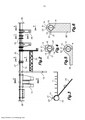
[0021] A figura 1 representa uma vista em perspectiva de uma estrutura de apoio híbrida metal-plástico aplicável ao suporte do painel de instrumentos de um veículo de acordo com um primeiro exemplo de realização da presente invenção, com um detalhe ampliado;[0021] Figure 1 represents a perspective view of a hybrid metal-plastic support structure applicable to the support of a vehicle's instrument panel according to a first embodiment of the present invention, with an enlarged detail;
[0022] A figura 2 representa uma vista frontal da estrutura de apoio híbrida da figura 1;[0022] Figure 2 represents a front view of the hybrid support structure of figure 1;
[0023] As figuras 3, 4, 5 e 6 representam vistas ampliadas em secção transversal tomadas, respectivamente, ao longo dos planos indicados A-A, B-B, C-C e D-D na figura 2;[0023] Figures 3, 4, 5 and 6 represent enlarged cross-sectional views taken, respectively, along the indicated planes A-A, B-B, C-C and D-D in figure 2;
[0024] A figura 7 representa uma vista em perspectiva parcial de uma montagem metálica que foima parte da estrutura de apoio híbrida do primeiro exemplo de realização;[0024] Figure 7 represents a partial perspective view of a metallic assembly that was part of the hybrid support structure of the first example of realization;
[0025] A figura 7A representa uma vista em perspectiva que mostra um detalhe opcional de um corpo tubular de metal que forma parte da montagem metálica;[0025] Figure 7A represents a perspective view showing an optional detail of a tubular metal body that forms part of the metallic assembly;
[0026] A figura 8 representa uma vista lateral parcial ampliada da extremidade de uma haste que foima um elemento de fixação de metal saliente na montagem metálica da figura 7;[0026] Figure 8 represents an enlarged partial side view of the end of a rod that forms a metal fastening element protruding in the metallic assembly of figure 7;
[0027] A figura 9 representa uma vista em perspectiva parcial da estrutura de apoio híbrida do primeiro exemplo de realização e de uma ferramenta giratória que pode ser utilizada para instalar ou remover as hastes;[0027] Figure 9 represents a partial perspective view of the hybrid support structure of the first embodiment and of a rotating tool that can be used to install or remove the rods;
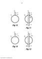
[0028] As figuras 10, 11, 12 e 13 representam vistas ampliadas em secção transversal que mostram diferentes maneiras de fixação das hastes que formam os elementos de fixação de metal salientes ao corpo tubular de metal de acordo com o primeiro exemplo de realização.[0028] Figures 10, 11, 12 and 13 represent enlarged cross-sectional views showing different ways of fixing the rods that form the metal fastening elements protruding from the metal tubular body according to the first embodiment.
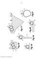
[0029] A figura 14 representa uma vista em perspectiva de uma estrutura de apoio híbrida metal-plástico aplicável ao suporte do painel de instrumentos de um veículo de acordo com um segundo exemplo de realização da presente invenção, com detalhes ampliados;[0029] Figure 14 represents a perspective view of a hybrid metal-plastic support structure applicable to the support of a vehicle's instrument panel according to a second embodiment of the present invention, with enlarged details;
[0030] A figura 15 representa uma vista frontal da estrutura de apoio híbrida da figura 10;[0030] Figure 15 represents a front view of the hybrid support structure of figure 10;
[0031] As figuras 16, 17, 18, 19 e 20 representam vistas ampliadas em secção transversal tomadas, respectivamente, ao longo dos planos indicados E-E, F-F, G-G, H-H e I-I na figura 15;[0031] Figures 16, 17, 18, 19 and 20 represent enlarged cross-sectional views taken, respectively, along the indicated plans E-E, F-F, G-G, H-H and I-I in figure 15;
[0032] A figura 21 representa uma vista ampliada em secção transversal que mostra o modo de fixação de uma haste que forma um elemento de fixação de metal saliente ao corpo tubular de metal de acordo com o segundo exemplo de realização;[0032] Figure 21 represents an enlarged cross-sectional view showing the way of fixing a rod that forms a metal fastening element protruding from the metal tubular body according to the second embodiment;
[0033] A figura 22 representa uma vista em perspectiva parcial de uma estrutura de apoio híbrida metal-plástico da presente invenção que inclui uma parede estrutural; e[0033] Figure 22 represents a partial perspective view of a hybrid metal-plastic support structure of the present invention that includes a structural wall; and
[0034] A figura 23 representa uma vista em perspectiva parcial que mostra a fixação de um elemento de reforço de metal e um corpo tubular de metal na parte metálica da estrutura de apoio híbrida metal-plástico da presente invenção.[0034] Figure 23 represents a partial perspective view showing the attachment of a metal reinforcement element and a metal tubular body to the metal part of the metal-plastic hybrid support structure of the present invention.
[0035] Fazendo referência em primeiro lugar às figuras 1 a 9, uma estrutura de apoio híbrida metal-plástico aplicável ao suporte do painel de instrumentos de um veículo de acordo com um primeiro exemplo de realização da presente invenção está, geralmente, designada com o número de referência 50. Neste primeiro exemplo de realização, a estrutura de apoio híbrida 50 está compreendida por um corpo tubular de metal 10 que possui um perfil fechado de corte transversal e comprimento adequado para ser instalada entre dois elementos laterais opostos do chassi de um veículo automotivo, transversal ao sentido de movimento de avanço do veículo. Este corpo tubular de metal 10 é um elemento estrutural que separa o compartimento interno do veículo do compartimento do motor e dá suporte ao painel de instrumentos do veículo. O corpo tubular de metal 10 do primeiro exemplo de realização é um tubo reto que possui um perfil circular de corte transversal que é constante ao longo do mesmo. Uma série de elementos funcionais plásticos separados estão sobremoldados em diferentes regiões do corpo tubular de metal 10, e estes elementos incluem, por exemplo, um suporte da coluna de direção 11 em uma primeira região lateral do corpo tubular de metal 10, pelo menos uma perna de apoio 12 e um suporte de console 25 em uma região central do corpo tubular de metal 10, um ou mais suportes de airbag 26 em uma segunda região lateral do corpo tubular de metal 10, além de diversos supoites de cabos 27 e outros suportes 28 para outros componentes.[0035] Referring first to figures 1 to 9, a hybrid metal-plastic support structure applicable to the support of a vehicle's instrument panel according to a first embodiment of the present invention is generally designated with the
[0036] Nas extremidades do corpo tubular de metal 10 há placas de fixação 29 retratadas apenas esquematicamente nas figuras 1 e 2 que, no exemplo mostrado, também são feitas de material plástico sobremoldado, embora pudessem, alternativamente, ser feitas de um material metálico fixado ao corpo tubular de metal 10 por solda ou adesão. Uma vez que todos os elementos funcionais plásticos 11, 12, 25-29 são obtidos por meio de uma única operação de sobremoldagem em um molde, todos os elementos funcionais plásticos 11, 12, 25-29 estão conectados uns aos outros por um ou mais tirantes de plástico 32 em contato com o corpo tubular de metal 10 como resultado de canais para o fluxo do material plástico fundido que conecta as cavidades para os diferentes elementos funcionais no molde.[0036] At the ends of the
[0037] Como mostrado na figura 7, para assegurar a fixação do material plástico sobremoldado que forma os elementos funcionais 11, 12, 25-29 ao corpo tubular de metal 10, uma série de elementos de fixação de metal salientes 14 estão fixados ao corpo tubular de metal 10 e distribuídos em diferentes regiões ao longo do mesmo em posições pré-selecionadas. Estes elementos de fixação de metal salientes 14 são compreendidos, preferivelmente, por uma haste substancialmente perpendicular ao sentido longitudinal do coipo tubular de metal 10, e relevos superficiais formados pelo menos em uma parte externa da citada haste, de modo que, na estrutura de apoio híbrida 50, os mencionados relevos superficiais estão em contato com o material plástico sobremoldado dos elementos funcionais 11, 12, 25-29. Os mencionados relevos superficiais das hastes que formam os elementos de fixação de metal salientes 14 estão, de maneira vantajosa, providos com uma rosca externa da haste, o que significa que parafusos ou pinos roscados dos tipos disponíveis comercialmente podem ser utilizado como elementos de fixação de metal salientes 14. A série de elementos funcionais plásticos 11, 12, 25-29 na estrutura de apoio híbrida 50 está sobremoldada em diferentes regiões separadas do corpo tubular de metal 10 no qual os elementos de fixação de metal salientes 14 estão fixados, de modo que cada elemento funcional plástico 11, 12 embute um ou mais dos elementos de fixação de metal salientes 14. A figura 7 mostra parcialmente somente o corpo tubular de metal 10 com os elementos de fixação de metal salientes 14 fixados no mesmo, e também um elemento de reforço de metal opcional 24 fixado ao corpo tubular de metal 10, por exemplo, por solda ou adesão, sobre o qual o citado suporte da coluna de direção 11 (figura 3) está sobremoldado.[0037] As shown in figure 7, to ensure the fastening of the overmolded plastic material that forms the
[0038] O corpo tubular de metal 10 possui, opcionalmente, em uma ou mais regiões do mesmo, recortes e/ou projeções superficiais 39, mostrados na figura 7A, nos quais uma ou mais partes do corpo plástico, por exemplo, um ou mais dos elementos funcionais plásticos 11, 12 (não mostrados na figura 7A), estão sobremoldados de modo que o material plástico embute os citados recortes e/ou saliências superficiais 39 estabelecendo um grau de fixação entre o metal e o plástico que é suficiente para suportar pequenas tensões torcionais sem a necessidade dos elementos de fixação de metal salientes 14. Obviamente, em uma mesma e única região do corpo tubular de metal 10, pode haver, simultaneamente, recortes e/ou saliências superficiais 39 e um ou mais elementos de fixação de metal salientes 14 embutidos no elemento funcional plástico. Estes recortes e/ou saliências superficiais podem ser facilmente formados por deformação superficial, por exemplo, por serrilhamento, ou pela remoção do material da superfície, por exemplo, por fresagem.[0038] The
[0039] A figura 8 mostra uma parte distai de um dos tais parafusos ou pinos roscados que formam os elementos de fixação de metal salientes 14 na estrutura de apoio híbrida 50 deste primeiro exemplo de realização. O parafuso ou pino roscado da figura 8 também está compreendido por uma configuração de aderência 21 adequada para ser presa por meio de uma ferramenta giratória 22 como, por exemplo, aquela mostrada na figura 9. Na estrutura de apoio híbrida 50 do primeiro exemplo de realização mostrada nas figuras 1 a 9, as hastes que formam os elementos de fixação de metal salientes 14 estão fixadas ao corpo tubular de metal 10 com uma força de fixação pré-determinada, e estão providas com a configuração de aderência correspondente 21, que pode ser alcançada através de uma abertura 23 (figura 9) formada no material plástico. Em outras palavras, o material plástico dos elementos funcionais embute as partes roscadas das hastes que foimam os elementos de fixação de metal salientes 14, porém as citadas aberturas 23 deixam exposta a extremidade distai de cada haste onde a configuração de aderência 21 é formada.[0039] Figure 8 shows a distal part of one of such screws or threaded pins that form the protruding
[0040] Portanto, como retratado na figura 9, a configuração de aderência 21 pode ser presa por meio da mencionada ferramenta giratória 22 para aplicar um torque pré-determinado à haste que é capaz de superar a mencionada força de fixação pré- determinada entre a haste e o corpo tubular de metal 10. Uma vez que a fixação entre a haste e o corpo tubular de metal 10 tenha sido quebrada, uma rotação subsequente da haste transmitida pela ferramenta giratória 22, e devido à rosca externa da haste em cooperação com a rosca interna formada no material plástico sobremoldado da mesma, o elemento de fixação de metal saliente 14 é extraído através da abertura 23 e, desta maneira, o elemento funcional plástico 11, 12, 25-29 fica parcialmente solto e pode ser, então, separado do coipo tubular de metal 10 deslizando-o axialmente até a sua extremidade para propósitos de reciclagem. Nas figuras 8 e 9, a configuração de aderência 21 das hastes que foimam os elementos de fixação de metal salientes 14 é um sulco transversal e a ferramenta giratória 22 uma chave de fenda manual. Não obstante, será altemativamente compreendido que a configuração de aderência pode apresentar qualquer outro foimato adequado para ser preso por uma ferramenta giratória correspondente com acionamento manual ou impulsionada por motor.[0040] Therefore, as shown in figure 9, the
[0041] Agora em relação às figuras 10-13, estão descritos abaixo diferentes exemplos alternativos de como as hastes que formam os elementos de fixação de metal salientes 14 podem ser fixadas ao corpo tubular de metal 10 de acordo com o primeiro exemplo de realização.[0041] Now in relation to figures 10-13, different alternative examples of how the rods forming the protruding
[0042] Na figura 10, a haste que forma o elemento de fixação de metal saliente 14 está disposta por uma junta de topo sobre o corpo tubular de metal 10 e fixada no mesmo por uma solda 30 na base. A solda 30 pode ser quebrada pelo torque aplicado por meio da citada ferramenta giratória 22 acoplada à configuração de aderência 21 da haste. A solda 30 pode, altemativamente, ser substituída por adesão que pode ser quebrada pelo citado torque.[0042] In figure 10, the rod that forms the projecting
[0043] Na figura 11, a haste que forma o elemento de fixação de metal saliente 14 é passada através de dois orifícios 20a, 20b formados em áreas opostas do corpo tubular de metal 10 e alinhados um com o outro. Os orifícios 20a, 20b não são roscados e haste está fixada ao corpo tubular de metal 10 por meio de uma solda 30 em uma região adjacente a um dos dois orifícios. A haste possui um comprimento adequado de modo que duas extremidades do mesmo projetam-se nos dois lados do coipo tubular de metal 10 proporcionando dois respectivos elementos de fixação de metal salientes 14 nas citadas áreas opostas do coipo tubular de metal 10. A solda 30 pode ser quebrada pelo torque aplicado por meio da ferramenta giratória 22 acoplada à configuração de aderência 21 da haste. A solda 30 pode, altemativamente, ser substituída por adesão que pode ser quebrada pelo citado torque.[0043] In figure 11, the rod forming the protruding
[0044] Na figura 12, a haste que forma o elemento de fixação de metal saliente 14 está fixada ao corpo tubular de metal 10 rosqueando-se a citada rosca externa em um orifício 19 correspondente com a rosca interna formada no corpo tubular de metal 10. O orifício 19 poderia, altemativamente, não ser provido com rosca e a haste poderia apresentar um auto-rosqueamento externo. De qualquer maneira, a fixação aparafusada da haste ao orifício 19 é reversível pelo torque aplicado por meio da ferramenta giratória 22 acoplada à configuração de aderência 21 da haste.[0044] In figure 12, the rod that forms the protruding
[0045] Na figura 13, a haste que forma o elemento de fixação de metal saliente 14 é passada através de dois orifícios alinhados 20a, 20b formados em áreas opostas do corpo tubular de metal 10. Um dos dois orifícios 20a possui rosca interna, e a rosca externa da haste está rosqueada no citado orifício roscado 20a. A haste é longa o suficiente de modo que as duas extremidades que se projetam da mesma proporcionam dois respectivos elementos de fixação de metal salientes 14 nas citadas áreas opostas do corpo tubular de metal 10. A fixação aparafusada da haste ao orifício 19 é reversível pelo torque aplicado por meio da ferramenta giratória 22 acoplada à configuração de aderência 21 da haste.[0045] In figure 13, the rod that forms the protruding
[0046] A figura 3 mostra o corte transversal de um elemento funcional que forma o suporte da coluna de direção 11. No plano do corte transversal mostrado, o material plástico do suporte da coluna de direção 11 está parcialmente sobremoldado no corpo tubular de metal 10 e no citado elemento de reforço de metal 24 que embute um dos elementos de fixação de metal salientes 14 que, por sua vez, está fixado ao corpo tubular de metal 10 como descrito acima em relação à figura 10. O material plástico do suporte da coluna de direção 11 embute completamente o elemento de reforço de metal 24 embora, altemativamente, poderia cobri-lo apenas parcialmente. No plano do corte transversal mostrado na figura 3, o material plástico do suporte da coluna de direção 11 circunda apenas parcialmente o corpo tubular de metal 10, embora, em outros planos, o material plástico circunde completamente o corpo tubular de metal 10.[0046] Figure 3 shows the cross section of a functional element that forms the support of the
[0047] A figura 4 mostra o corte transversal de um elemento funcional que forma o suporte de cabos 27. No plano do corte transversal mostrado, o material plástico do suporte de cabos 27 está sobremoldado no corpo tubular de metal 10, circundando-o completamente e embutindo três dos elementos de fixação de metal salientes 14 que possuem os seus eixos em um mesmo e único plano. Dois dos elementos de fixação de metal salientes 14 estão providos de uma única haste fixada no corpo tubular de metal 10 como descrito em relação à figura 11 ou à figura 13, enquanto o outro está provido de uma haste fixada no corpo tubular de metal 10 como descrito em relação à figura 10, embora pudesse, altemativamente, ser como descrito em relação à figura 12.[0047] Figure 4 shows the cross section of a functional element that forms the
[0048] A figura 5 mostra o corte transversal de um elemento funcional que forma o suporte de airbag 26. No plano do corte transversal mostrado, o material plástico do suporte de airbag 26 está sobremoldado no corpo tubular de metal 10, circundando- o completamente e embutindo dois dos elementos de fixação de metal salientes 14 providos de uma única haste fixada ao corpo tubular de metal 10 como descrito em relação à figura 11 ou à figura 13.[0048] Figure 5 shows the cross-section of a functional element that forms the
[0049] A figura 6 mostra o corte transversal de um elemento funcional que forma um suporte 28 para um componente. No plano do corte transversal mostrado, o material plástico do suporte 28 está sobremoldado no corpo tubular de metal 10, circundando-o completamente e embutindo três dos elementos de fixação de metal salientes 14, sendo que os eixos dos mesmos estão em um mesmo e único plano. Dois dos elementos de fixação de metal salientes 14 estão providos por uma única haste fixada ao corpo tubular de metal 10 como descrito em relação à figura 11 ou à figura 13, enquanto o outro está provido por uma haste fixada ao corpo tubular de metal 10 como descrito em relação à figura 10, embora pudesse, altemativamente, ser como descrito em relação à figura 12.[0049] Figure 6 shows the cross section of a functional element that forms a
[0050] Na estrutura de apoio híbrida 50 do primeiro exemplo de realização, um primeiro grupo das hastes que formam os elementos de fixação de metal salientes 14 está disposto com os seus eixos longitudinais paralelos uns aos outros e, em um primeiro plano, substancialmente paralelos ao sentido de desmoldagem do material plástico dos elementos funcionais 11, 12, 25-29, enquanto um segundo grupo das hastes que formam os elementos de fixação de metal salientes 14 está disposto com os seus eixos longitudinais paralelos uns aos outros e, em um segundo plano, substancialmente perpendiculares ao citado sentido de desmoldagem. Esta disposição permite a desmoldagem e facilita tanto a instalação dos elementos de fixação de metal salientes 14 ao corpo tubular de metal 10 quanto a extração dos elementos de fixação de metal salientes 14 para propósitos de reciclagem. Todas as hastes que formam os elementos de fixação de metal salientes 14 da estrutura de apoio híbrida 50 poderiam, altemativamente, estar dispostas com os seus eixos longitudinais paralelos uns aos outros e em um único e mesmo plano substancialmente paralelos ao sentido de desmoldagem para os mesmos propósitos.[0050] In the
[0051] As figuras 14-21 descrevem agora uma estrutura de apoio híbrida 50 aplicada ao suporte do painel de instrumentos de um veículo de acordo com um segundo exemplo de realização da presente invenção. Como mostrado na figura 14, a estrutura de apoio híbrida 50 deste segundo exemplo de realização está compreendida por um corpo tubular de metal 10 feito de um tubo reto que possui um perfil constante de corte transversal fechado ao longo do mesmo, e possui uma faceta plana no sentido longitudinal. Em uma primeira região lateral do corpo tubular de metal 10, está fixado um corpo de reforço tubular de metal 15 que, no exemplo mostrado, é um pedaço de um tubo que possui as mesmas características que o corpo tubular de metal 10. O corpo tubular de metal 10 e o corpo de reforço tubular de metal 15 estão mutuamente fixados, por exemplo, por solda ou adesão, com as respectivas facetas planares voltadas para si e em contato. No corpo tubular de metal 10, estão fixados elementos de fixação de metal salientes 14 em regiões separadas do mesmo, e no citado corpo de reforço tubular de metal 15, estão fixados outros elementos de fixação de metal salientes 16 que possuem as mesmas características. Cada um dos elementos de fixação de metal salientes 14, 16 está compreendido, preferivelmente, por uma haste substancialmente perpendicular ao sentido longitudinal do correspondente corpo tubular de metal 10 ou corpo de reforço tubular de metal 15, com os relevos superficiais formados em uma parte externa da haste. Uma série de elementos funcionais plásticos 11, 12, 25-29 estão sobremoldados na montagem metálica estrutural formada pelo corpo tubular de metal 10 e pelo corpo de reforço tubular de metal 15, de modo que alguns dos elementos funcionais plásticos, por exemplo, uma perna de apoio 12, um suporte de console 25, um ou mais suportes de airbag 26, diversos suportes de cabos 27, outros suportes 28 para outros componentes, e uma placa de fixação terminal 29 estão sobremoldados somente no corpo tubular de metal 10 que embute um ou mais dos elementos de fixação de metal salientes 14, enquanto outros elementos funcionais plásticos, por exemplo, o suporte da coluna de direção 11, estão sobremoldados parcialmente no corpo tubular de metal 10 que embute um ou mais dos elementos de fixação de metal salientes 14 e parcialmente no corpo de reforço tubular de metal 15 que embute um ou mais dos elementos de fixação de metal salientes 16.[0051] Figures 14-21 now describe a
[0052] Como está melhor mostrado na figura 21, neste segundo exemplo de realização, cada um dos elementos de fixação de metal salientes 14, 16 está compreendido por uma haste com rosca externa e provida por um anel 31 ao redor da sua extremidade proximal e que não possui a configuração de aderência na sua extremidade distai, sendo que a estrutura de apoio híbrida 50 do segundo exemplo de realização não está preparada para facilitar a reciclagem. Os tipos de hastes que formam os elementos de fixação de metal salientes 14, 16 estão disponíveis comercialmente e estão providas para serem fixadas por junta de topo na superfície externa do corpo tubular de metal 10 ou no corpo de reforço tubular de metal 15 por meio de uma solda 30.[0052] As is best shown in figure 21, in this second embodiment, each of the protruding
[0053] A figura 16 mostra o corte transversal de um elemento funcional que foima um suporte 33 para um componente. No plano do corte transversal mostrado, o material plástico do suporte 33 está parcialmente sobremoldado no corpo tubular de metal 10 que embute dois dos elementos de fixação de metal salientes 14 fixados no mesmo e parcialmente no corpo de reforço tubular de metal 15 que embute dois dos elementos de fixação de metal salientes 16 fixados no mesmo. O material plástico do suporte 33 circunda completamente a montagem metálica estrutural foimada pelo corpo tubular de metal 10 e pelo corpo de reforço tubular de metal 15.[0053] Figure 16 shows the cross section of a functional element that was a
[0054] A figura 17 mostra o corte transversal de um elemento funcional que foima o suporte da coluna de direção 11. No plano do corte transversal mostrado, o material plástico do suporte da coluna de direção está parcialmente sobremoldado no corpo tubular de metal 10 que embute dois dos elementos de fixação de metal salientes 14 fixados no mesmo e parcialmente no corpo de reforço tubular de metal 15 que embute dois dos elementos de fixação de metal salientes 16 fixados no mesmo. Neste caso, o material plástico do suporte da coluna de direção 11 circunda completamente a montagem metálica estrutural formada pelo corpo tubular de metal 10 e pelo corpo de reforço tubular de metal 15 e não possui um elemento de reforço de metal no mesmo.[0054] Figure 17 shows the cross section of a functional element that forms the support of the
[0055] A figura 18 mostra o coife transversal de um elemento funcional que forma o suporte de cabos 27. No plano do corte transversal mostrado, o material plástico do suporte de cabos 27 está sobremoldado somente no corpo tubular de metal 10, circundando-o completamente e embutindo dois dos elementos de fixação de metal salientes 14.[0055] Figure 18 shows the cross-section of a functional element that forms the
[0056] A figura 19 mostra o corte transversal de um elemento funcional que foima um suporte 28 para um componente. No plano do corte transversal mostrado, o material plástico do suporte 28 está sobremoldado somente no corpo tubular de metal 10, circundando-o completamente e embutindo dois dos elementos de fixação de metal salientes 14.[0056] Figure 19 shows the cross section of a functional element that was a
[0057] A figura 20 mostra o corte transversal de um elemento funcional que forma um suporte de airbag 26. No plano do corte transversal mostrado, o material plástico do suporte de airbag 26 está sobremoldado somente no corpo tubular de metal 10, circundando-o completamente e embutindo dois dos elementos de fixação de metal salientes 14.[0057] Figure 20 shows the cross-section of a functional element that forms an
[0058] Os elementos estruturais plásticos da estrutura de apoio híbrida 50 são formados por vigas de reforço e paredes relativamente finas para proporcionar a resistência exigida com a menor quantidade possível de material plástico. Nas figuras 4-6 do primeiro exemplo de realização e nas figuras 16-20 do segundo exemplo de realização, os planos dos cortes transversais mostrados passam através dos eixos dos elementos de fixação de metal salientes 14, 16 e também através do centro das respectivas vigas de reforço, que podem oferecer a falsa impressão de que os elementos estruturais plásticos são sólidos. Nas regiões em que o material plástico dos elementos estruturais está em contato com os elementos de fixação de metal salientes 14, 16, as vigas e paredes relativamente finas dos elementos estruturais possuem ressaltos ou projeções 34, 36 que cobrem pelo menos lateralmente os elementos de fixação de metal salientes 14, 16, como está melhor mostrado nos detalhes ampliados das figuras 1, 9 e 14.[0058] The plastic structural elements of the
[0059] Na figura 22, está mostrada uma característica opcional da estrutura de apoio híbrida da presente invenção, onde o corpo plástico sobremoldado define uma parede estrutural 37 que se estende a partir de uma superfície externa do corpo tubular de metal 10 para fora e ao longo de uma parte do mesmo. Esta parede estrutural 37 está dimensionada para proporcionar, juntamente com o corpo tubular de metal 10, uma área de corte transversal com um momento de inércia desejado. No exemplo mostrado, a parede estrutural 37 está conectada lateralmente a elementos funcionais 28, 29 e possui uma base em contato com o corpo tubular de metal 10. O material plástico dos elementos funcionais 28, 29 forma ressaltos ou projeções 34 nos quais elementos de fixação de metal salientes 14 correspondentes fixados ao coi-po tubular de metal 10 estão embutidos. A base da parede estrutural 37 pode, opcionalmente, incluir também ressaltos ou projeções 34 que embutem elementos de fixação de metal salientes 14 fixados ao corpo tubular de metal 10. Embora não estejam mostradas na figura 22, flanges podem se estender lateralmente da extremidade distai da parede estrutural 37 para configurar, por exemplo, um perfil em formato T-, L- ou Y em corte transversal para a instalação da parede estrutural com os flanges. O corpo plástico sobremoldado pode também definir vigas de reforço (não mostradas) que conectam a parede estrutural 37 e a superfície externa do corpo tubular de metal 10 e, opcionalmente, os elementos funcionais plásticos 28, 29.[0059] In figure 22, an optional feature of the hybrid support structure of the present invention is shown, where the overmolded plastic body defines a
[0060] Em relação à figura 23, a fixação do elemento de reforço de metal 24 ao corpo tubular de metal 10 está descrito de maneira alternativa em relação à solda ou adesão descrita acima em referência à figura 7. Aqui, o elemento de reforço de metal 24 possui uma região 24a provida para estar em contato com o corpo tubular de metal 10 na qual um par de orifícios 38 está formado, e dois dos elementos de fixação de metal salientes 14 fixados ao corpo tubular de metal 10 serão passados através dos citados orifícios 38 de modo a se projetarem no lado externo do elemento de reforço de metal 24. De maneira semelhante ao que foi descrito acima em relação à figura 3, depois da operação de sobremoldagem, uma parte do corpo plástico, por exemplo, parte de um elemento funcional na forma de um suporte da coluna de direção 11, está parcialmente sobremoldado no citado elemento de reforço de metal 24 e parcialmente no corpo tubular de metal 10 que embute, neste caso, os elementos de fixação de metal salientes 14 e os orifícios 38 através dos quais eles estão inseridos, estabelecendo, portanto, uma fixação forte entre o elemento de reforço de metal 24, o corpo tubular de metal 10 e o corpo plástico sobremoldado sem a necessidade de solda ou adesão.[0060] In relation to figure 23, the attachment of the
[0061] Um especialista na área poderia introduzir modificações e variações nos exemplos de realização mostrados e descritos sem se desviar do escopo da presente invenção. Por exemplo, o corpo tubular de metal 10 pode apresentar algumas curvas ou uma leve curva geral ao invés de ser completamente reto, e/ou pode apresentar um perfil variável em corte transversal ao longo do mesmo ao invés de ser um perfil constante em corte transversal. Também será compreendido que a estrutura de apoio híbrida metal-plástico da presente invenção pode ser aplicada, além do suporte do painel de instrumentos, a outros componentes de um veículo como, por exemplo, uma travessa de reforço do para-choques, uma estrutura de apoio da parte frontal, etc.[0061] A person skilled in the art could introduce modifications and variations to the shown and described examples of realization without departing from the scope of the present invention. For example, the
[0062] O escopo da presente invenção está definido nos desenhos em anexo.[0062] The scope of the present invention is defined in the attached drawings.
Claims (15)
Applications Claiming Priority (3)
| Application Number | Priority Date | Filing Date | Title |
|---|---|---|---|
| EPE09380060.5 | 2009-03-25 | ||
| EP09380060A EP2233385B1 (en) | 2009-03-25 | 2009-03-25 | Metal-plastic hybrid support structure applicable to a vehicle instrument board support |
| PCT/IB2010/000678 WO2010109314A1 (en) | 2009-03-25 | 2010-03-22 | Metal-plastic hybrid support structure applicable to a dashboard support of a vehicle |
Publications (3)
| Publication Number | Publication Date |
|---|---|
| BRPI1010292A2 BRPI1010292A2 (en) | 2019-03-06 |
| BRPI1010292A8 BRPI1010292A8 (en) | 2019-03-26 |
| BRPI1010292B1 true BRPI1010292B1 (en) | 2020-08-04 |
Family
ID=40732230
Family Applications (1)
| Application Number | Title | Priority Date | Filing Date |
|---|---|---|---|
| BRPI1010292-2A BRPI1010292B1 (en) | 2009-03-25 | 2010-03-22 | METAL-PLASTIC HYBRID SUPPORT STRUCTURE APPLICABLE TO A DASHBOARD SUPPPORT OF A VEHICLE |
Country Status (6)
| Country | Link |
|---|---|
| US (1) | US8919855B2 (en) |
| EP (1) | EP2233385B1 (en) |
| AT (1) | ATE534571T1 (en) |
| BR (1) | BRPI1010292B1 (en) |
| ES (1) | ES2376219T3 (en) |
| WO (1) | WO2010109314A1 (en) |
Families Citing this family (29)
| Publication number | Priority date | Publication date | Assignee | Title |
|---|---|---|---|---|
| ATE534571T1 (en) | 2009-03-25 | 2011-12-15 | Barcelona Technical Ct Sl | METAL-PLASTIC HYBRID SUPPORT STRUCTURE FOR INSTRUMENT PANEL SUPPORT |
| US20140103685A1 (en) * | 2011-02-23 | 2014-04-17 | Ayyakannu Mani | Lightweight Cross-Car Beam and Method of Construction |
| FR2975963B1 (en) * | 2011-06-06 | 2014-07-04 | Peugeot Citroen Automobiles Sa | REINFORCING PART OF A VEHICLE BOARD, IN PARTICULAR A MOTOR VEHICLE. |
| KR101755706B1 (en) * | 2011-09-05 | 2017-07-10 | 현대자동차주식회사 | Cowl cross structure |
| WO2014006275A1 (en) * | 2012-07-03 | 2014-01-09 | Peugeot Citroen Automobiles Sa | Reinforcement part for a dashboard of a vehicle, in particular a motor vehicle, and reinforced dashboard |
| FR2996204B1 (en) * | 2012-10-03 | 2014-09-19 | Peugeot Citroen Automobiles Sa | DEVICE FOR FASTENING THE STEERING COLUMN OF A MOTOR VEHICLE TO THE DASHBOARD TRAVERSE AND TO A PART OF THE STRUCTURE OF THE VEHICLE BOX |
| FR3000007A3 (en) * | 2012-12-20 | 2014-06-27 | Renault Sa | Cross-piece for instrument panel in driver's cab of vehicle, has fixing units provided at top and bottom of vertical legs for fixing vertical legs at main transverse metal element and at floor of vehicle |
| DE102013108101A1 (en) * | 2013-07-29 | 2015-02-19 | Dr. Ing. H.C. F. Porsche Aktiengesellschaft | center console |
| FR3014816B1 (en) * | 2013-12-18 | 2016-02-05 | Peugeot Citroen Automobiles Sa | ASSEMBLY COMPRISING A DASHBOARD TRAILER AND A FIXING BRACKET FOR AN INFLATABLE CUSHION |
| US9446800B2 (en) * | 2014-05-30 | 2016-09-20 | Van-Rob Inc. | Vehicle cross-support member with hybrid metal joint |
| JP6452972B2 (en) * | 2014-07-09 | 2019-01-16 | ユニプレス株式会社 | Steering member |
| CN107000796B (en) * | 2015-09-17 | 2018-09-14 | 沙特基础工业全球技术公司 | Lateral direction of car component and related methods |
| FR3043050B1 (en) * | 2015-10-29 | 2017-11-24 | Faurecia Interieur Ind | VEHICLE TRAVERSE |
| GB2563368B (en) * | 2016-03-30 | 2021-10-20 | Zsi Inc | Insulated riser clamp |
| JP6755810B2 (en) * | 2017-01-31 | 2020-09-16 | 株式会社Uacj | Instrument panel beam, pair of brackets and instrument panel beam junction |
| JP2018158653A (en) * | 2017-03-23 | 2018-10-11 | アイシン精機株式会社 | Instrument panel reinforcement |
| EP3600849B1 (en) * | 2017-03-24 | 2021-06-16 | Telsonic Holding AG | Add-on part for connecting to a component |
| JP6745253B2 (en) * | 2017-03-28 | 2020-08-26 | 株式会社神戸製鋼所 | Vehicle structural member and manufacturing method thereof |
| JP6954777B2 (en) * | 2017-07-12 | 2021-10-27 | 株式会社栗本鐵工所 | Steering support structure |
| JP6953846B2 (en) * | 2017-07-12 | 2021-10-27 | トヨタ自動車株式会社 | Steering support structure |
| FR3069517B1 (en) * | 2017-07-26 | 2019-08-23 | Faurecia Interieur Industrie | FORCE FRONT END BOARD TRAILER FOR AUTOMOTIVE VEHICLE |
| JP6777038B2 (en) * | 2017-07-28 | 2020-10-28 | トヨタ自動車株式会社 | Reinforced structure at the front of the passenger compartment |
| EP3820763A4 (en) | 2018-07-12 | 2022-04-13 | Shanghai Yanfeng Jin Qiao Automotive Trim Systems Co., Ltd. | Cross-member structure for vehicle |
| US11001310B2 (en) * | 2019-02-05 | 2021-05-11 | GM Global Technology Operations LLC | HVAC instrument panel bracket |
| CN110239632A (en) * | 2019-07-17 | 2019-09-17 | 上海延锋金桥汽车饰件系统有限公司 | Dashboard cross member |
| DE102019124298A1 (en) | 2019-09-10 | 2021-03-11 | Kirchhoff Automotive Deutschland Gmbh | Instrument panel support for a motor vehicle |
| KR20210067799A (en) * | 2019-11-29 | 2021-06-08 | 현대모비스 주식회사 | Hybrid cowl cross bar and its manufacturing method |
| KR20220006801A (en) * | 2020-07-09 | 2022-01-18 | 현대자동차주식회사 | Method for Manufacturing of the Light Weight Cowl cross bar for vehicle |
| DE102022118863A1 (en) | 2022-07-27 | 2024-02-01 | Smrc Automotive Holdings Netherlands B.V. | Hybrid support structure made of metal and plastic, in particular for a dashboard of a vehicle, and process for producing it |
Family Cites Families (10)
| Publication number | Priority date | Publication date | Assignee | Title |
|---|---|---|---|---|
| JPS62118961A (en) * | 1985-11-15 | 1987-05-30 | Asahi Malleable Iron Co Ltd | Method for forming internal screw part to casting |
| US5676216A (en) * | 1994-04-14 | 1997-10-14 | Ford Global Technologies, Inc. | Structural two-piece composite instrument panel cross-beam with integrated air distribution system |
| US6547210B1 (en) * | 2000-02-17 | 2003-04-15 | Wright Medical Technology, Inc. | Sacrificial insert for injection molding |
| US20020160145A1 (en) * | 2001-02-28 | 2002-10-31 | Bauhoff Michael J. | Integral structures of metal and plastic with fastening means |
| FR2834271B1 (en) * | 2001-12-27 | 2004-02-20 | Sai Automotive Allibert Ind | DASHBOARD STRUCTURAL ASSEMBLY AND METHOD FOR MAKING SAME |
| DE10360045A1 (en) * | 2003-12-18 | 2005-07-21 | Intier Automotive Interiors Gmbh | Hydrid cross member for vehicle has metal cross brace with section in form of open channel extending in direction of main direction of cross member, with longitudinal edges of latter section connected to structural element of plastic |
| US7216927B2 (en) * | 2004-12-03 | 2007-05-15 | Gm Global Technology Operations, Inc. | Lightweight hybrid tubular/casting instrument panel beam |
| FR2884215B1 (en) * | 2005-04-06 | 2007-07-20 | Faurecia Interieur Ind Snc | REINFORCING STRUCTURE FOR A MOTOR VEHICLE CAPABLE OF LIMITING THE DASHBOARD VIBRATIONS AND THE CORRESPONDING MOTOR VEHICLE. |
| ATE512823T1 (en) * | 2006-04-05 | 2011-07-15 | Denso Thermal Systems Spa | DASHBOARD OF A VEHICLE |
| ATE534571T1 (en) | 2009-03-25 | 2011-12-15 | Barcelona Technical Ct Sl | METAL-PLASTIC HYBRID SUPPORT STRUCTURE FOR INSTRUMENT PANEL SUPPORT |
-
2009
- 2009-03-25 AT AT09380060T patent/ATE534571T1/en active
- 2009-03-25 ES ES09380060T patent/ES2376219T3/en active Active
- 2009-03-25 EP EP09380060A patent/EP2233385B1/en active Active
-
2010
- 2010-03-22 US US13/257,294 patent/US8919855B2/en active Active
- 2010-03-22 WO PCT/IB2010/000678 patent/WO2010109314A1/en active Application Filing
- 2010-03-22 BR BRPI1010292-2A patent/BRPI1010292B1/en active IP Right Grant
Also Published As
| Publication number | Publication date |
|---|---|
| EP2233385B1 (en) | 2011-11-23 |
| US8919855B2 (en) | 2014-12-30 |
| EP2233385A1 (en) | 2010-09-29 |
| BRPI1010292A8 (en) | 2019-03-26 |
| BRPI1010292A2 (en) | 2019-03-06 |
| US20120032044A1 (en) | 2012-02-09 |
| WO2010109314A1 (en) | 2010-09-30 |
| ATE534571T1 (en) | 2011-12-15 |
| ES2376219T3 (en) | 2012-03-12 |
Similar Documents
| Publication | Publication Date | Title |
|---|---|---|
| BRPI1010292B1 (en) | METAL-PLASTIC HYBRID SUPPORT STRUCTURE APPLICABLE TO A DASHBOARD SUPPPORT OF A VEHICLE | |
| US10150259B2 (en) | Method for manufacturing a bumper structure | |
| WO2004071741A1 (en) | Method for the production of a structural part comprising a rigid material and a plastic material, and structural composite part thus obtained | |
| ES2411088T3 (en) | Polymeric material wheel | |
| EP1686044B1 (en) | Transverse support beam for a vehicle | |
| RU2342276C1 (en) | Motor vehicle body | |
| US8029045B2 (en) | Crossbeam for a motor vehicle | |
| BRPI1003583A2 (en) | nodal element for a vehicle chassis structure, hollow chassis profile for joining a nodal element and method for establishing a positive and non-positive connection between a nodal element and a hollow chassis profile | |
| JPH03501009A (en) | Three-dimensional vehicle frame and method for manufacturing three-dimensional vehicle frame members | |
| PT771696E (en) | DEVICE FOR FIXING A MODULE OF A PNEUMATIC BAG | |
| US7921564B2 (en) | Method of assembling a crossbar with a dashboard, and a centering device | |
| JP2002526321A (en) | Elongated hollow support structure with lateral flanges at each end | |
| PT103758A (en) | METHOD OF MANUFACTURING A DRIVEWAY FOR MOTOR VEHICLES AND THEIR TRAVEL | |
| CN106163904A (en) | Motor vehicles facade module | |
| DE102017200829B4 (en) | Vehicle frame for holding an energy store | |
| ES2258584T3 (en) | CROSSBOOK OF A VEHICLE. | |
| ES2207957T3 (en) | CLAMPING DEVICE WITH A SCREW PROVIDED WITH A PLASTIC MATERIAL COATING. | |
| BR112012008247B1 (en) | coupling head with housing made of plastic as an injection molded raw part | |
| ES2300756T3 (en) | TRAVEL SUPPORT FOR INSTRUMENT BOARD. | |
| EP1352813B1 (en) | Process of manufacturing and mounting a cross-member and cross-member obtained by this process | |
| EP2505468A2 (en) | Windshield device for saddle-ride type vehicles | |
| JP2008279951A (en) | Brace and vehicle body lower part structure | |
| JP6463284B2 (en) | Steel ground cover mounting structure | |
| JP4897463B2 (en) | Spoiler and manufacturing method thereof | |
| ES2279915T3 (en) | CONNECTION BY CLIMBING OF CARCASE PARTS. |
Legal Events
| Date | Code | Title | Description |
|---|---|---|---|
| B06F | Objections, documents and/or translations needed after an examination request according [chapter 6.6 patent gazette] | ||
| B06U | Preliminary requirement: requests with searches performed by other patent offices: procedure suspended [chapter 6.21 patent gazette] | ||
| B06A | Patent application procedure suspended [chapter 6.1 patent gazette] | ||
| B09A | Decision: intention to grant [chapter 9.1 patent gazette] | ||
| B16A | Patent or certificate of addition of invention granted [chapter 16.1 patent gazette] |
Free format text: PRAZO DE VALIDADE: 10 (DEZ) ANOS CONTADOS A PARTIR DE 04/08/2020, OBSERVADAS AS CONDICOES LEGAIS. |