BRPI1007528B1 - SYSTEM FOR GENERATING AN OUTPUT AUDIO SIGNAL FROM AN INPUT AUDIO SIGNAL USING A T TRANSPOSITION FACTOR, METHOD FOR TRANSPORTING AN INPUT AUDIO SIGNAL BY A T TRANSPOSITION FACTOR AND STORAGE MEDIA - Google Patents
SYSTEM FOR GENERATING AN OUTPUT AUDIO SIGNAL FROM AN INPUT AUDIO SIGNAL USING A T TRANSPOSITION FACTOR, METHOD FOR TRANSPORTING AN INPUT AUDIO SIGNAL BY A T TRANSPOSITION FACTOR AND STORAGE MEDIA Download PDFInfo
- Publication number
- BRPI1007528B1 BRPI1007528B1 BRPI1007528-3A BRPI1007528A BRPI1007528B1 BR PI1007528 B1 BRPI1007528 B1 BR PI1007528B1 BR PI1007528 A BRPI1007528 A BR PI1007528A BR PI1007528 B1 BRPI1007528 B1 BR PI1007528B1
- Authority
- BR
- Brazil
- Prior art keywords
- audio signal
- window
- analysis
- synthesis
- transposition
- Prior art date
Links
- 230000017105 transposition Effects 0.000 title claims abstract description 170
- 238000000034 method Methods 0.000 title claims abstract description 58
- 230000005236 sound signal Effects 0.000 title claims abstract description 52
- 238000004458 analytical method Methods 0.000 claims abstract description 191
- 230000015572 biosynthetic process Effects 0.000 claims abstract description 176
- 238000003786 synthesis reaction Methods 0.000 claims abstract description 174
- RVRCFVVLDHTFFA-UHFFFAOYSA-N heptasodium;tungsten;nonatriacontahydrate Chemical compound O.O.O.O.O.O.O.O.O.O.O.O.O.O.O.O.O.O.O.O.O.O.O.O.O.O.O.O.O.O.O.O.O.O.O.O.O.O.O.[Na+].[Na+].[Na+].[Na+].[Na+].[Na+].[Na+].[W].[W].[W].[W].[W].[W].[W].[W].[W].[W].[W] RVRCFVVLDHTFFA-UHFFFAOYSA-N 0.000 claims abstract description 51
- 230000009466 transformation Effects 0.000 claims abstract description 21
- 230000001131 transforming effect Effects 0.000 claims abstract description 6
- 238000005070 sampling Methods 0.000 claims description 44
- 238000012545 processing Methods 0.000 claims description 12
- 230000008602 contraction Effects 0.000 claims description 10
- 230000008859 change Effects 0.000 claims description 7
- 238000000605 extraction Methods 0.000 abstract description 2
- 230000006870 function Effects 0.000 description 20
- 230000001052 transient effect Effects 0.000 description 20
- 230000009467 reduction Effects 0.000 description 14
- 230000003595 spectral effect Effects 0.000 description 14
- 238000006243 chemical reaction Methods 0.000 description 13
- 230000004044 response Effects 0.000 description 10
- 238000012952 Resampling Methods 0.000 description 8
- 230000009286 beneficial effect Effects 0.000 description 8
- 230000000694 effects Effects 0.000 description 7
- 238000002592 echocardiography Methods 0.000 description 6
- 238000001228 spectrum Methods 0.000 description 6
- 238000001514 detection method Methods 0.000 description 5
- 230000004048 modification Effects 0.000 description 5
- 238000012986 modification Methods 0.000 description 5
- 230000000737 periodic effect Effects 0.000 description 5
- 230000010363 phase shift Effects 0.000 description 5
- 230000010076 replication Effects 0.000 description 5
- 230000005284 excitation Effects 0.000 description 4
- 239000000284 extract Substances 0.000 description 4
- 230000006872 improvement Effects 0.000 description 4
- 238000013459 approach Methods 0.000 description 3
- 230000006835 compression Effects 0.000 description 3
- 238000007906 compression Methods 0.000 description 3
- 238000011161 development Methods 0.000 description 3
- 238000005516 engineering process Methods 0.000 description 3
- 238000007781 pre-processing Methods 0.000 description 3
- 230000003044 adaptive effect Effects 0.000 description 2
- 238000013461 design Methods 0.000 description 2
- 238000004519 manufacturing process Methods 0.000 description 2
- 230000000717 retained effect Effects 0.000 description 2
- 230000002123 temporal effect Effects 0.000 description 2
- 241000282421 Canidae Species 0.000 description 1
- 108010076504 Protein Sorting Signals Proteins 0.000 description 1
- 238000009825 accumulation Methods 0.000 description 1
- 230000004075 alteration Effects 0.000 description 1
- 230000002238 attenuated effect Effects 0.000 description 1
- 238000004590 computer program Methods 0.000 description 1
- 238000012937 correction Methods 0.000 description 1
- 230000003111 delayed effect Effects 0.000 description 1
- 230000001419 dependent effect Effects 0.000 description 1
- 230000001627 detrimental effect Effects 0.000 description 1
- 238000006073 displacement reaction Methods 0.000 description 1
- 230000009977 dual effect Effects 0.000 description 1
- 238000004134 energy conservation Methods 0.000 description 1
- 238000001914 filtration Methods 0.000 description 1
- 230000004927 fusion Effects 0.000 description 1
- 238000009434 installation Methods 0.000 description 1
- 230000007774 longterm Effects 0.000 description 1
- 238000013507 mapping Methods 0.000 description 1
- 239000000203 mixture Substances 0.000 description 1
- 230000003287 optical effect Effects 0.000 description 1
- 238000012805 post-processing Methods 0.000 description 1
- 230000036278 prepulse Effects 0.000 description 1
- 230000008569 process Effects 0.000 description 1
- 238000011002 quantification Methods 0.000 description 1
- 238000004445 quantitative analysis Methods 0.000 description 1
- 238000007493 shaping process Methods 0.000 description 1
- 239000007787 solid Substances 0.000 description 1
- 239000003351 stiffener Substances 0.000 description 1
- 230000007704 transition Effects 0.000 description 1
Images


Classifications
-
- G—PHYSICS
- G10—MUSICAL INSTRUMENTS; ACOUSTICS
- G10L—SPEECH ANALYSIS TECHNIQUES OR SPEECH SYNTHESIS; SPEECH RECOGNITION; SPEECH OR VOICE PROCESSING TECHNIQUES; SPEECH OR AUDIO CODING OR DECODING
- G10L21/00—Speech or voice signal processing techniques to produce another audible or non-audible signal, e.g. visual or tactile, in order to modify its quality or its intelligibility
- G10L21/02—Speech enhancement, e.g. noise reduction or echo cancellation
- G10L21/038—Speech enhancement, e.g. noise reduction or echo cancellation using band spreading techniques
-
- G—PHYSICS
- G10—MUSICAL INSTRUMENTS; ACOUSTICS
- G10L—SPEECH ANALYSIS TECHNIQUES OR SPEECH SYNTHESIS; SPEECH RECOGNITION; SPEECH OR VOICE PROCESSING TECHNIQUES; SPEECH OR AUDIO CODING OR DECODING
- G10L19/00—Speech or audio signals analysis-synthesis techniques for redundancy reduction, e.g. in vocoders; Coding or decoding of speech or audio signals, using source filter models or psychoacoustic analysis
- G10L19/02—Speech or audio signals analysis-synthesis techniques for redundancy reduction, e.g. in vocoders; Coding or decoding of speech or audio signals, using source filter models or psychoacoustic analysis using spectral analysis, e.g. transform vocoders or subband vocoders
- G10L19/0212—Speech or audio signals analysis-synthesis techniques for redundancy reduction, e.g. in vocoders; Coding or decoding of speech or audio signals, using source filter models or psychoacoustic analysis using spectral analysis, e.g. transform vocoders or subband vocoders using orthogonal transformation
-
- G—PHYSICS
- G10—MUSICAL INSTRUMENTS; ACOUSTICS
- G10L—SPEECH ANALYSIS TECHNIQUES OR SPEECH SYNTHESIS; SPEECH RECOGNITION; SPEECH OR VOICE PROCESSING TECHNIQUES; SPEECH OR AUDIO CODING OR DECODING
- G10L19/00—Speech or audio signals analysis-synthesis techniques for redundancy reduction, e.g. in vocoders; Coding or decoding of speech or audio signals, using source filter models or psychoacoustic analysis
- G10L19/02—Speech or audio signals analysis-synthesis techniques for redundancy reduction, e.g. in vocoders; Coding or decoding of speech or audio signals, using source filter models or psychoacoustic analysis using spectral analysis, e.g. transform vocoders or subband vocoders
- G10L19/022—Blocking, i.e. grouping of samples in time; Choice of analysis windows; Overlap factoring
-
- G—PHYSICS
- G10—MUSICAL INSTRUMENTS; ACOUSTICS
- G10L—SPEECH ANALYSIS TECHNIQUES OR SPEECH SYNTHESIS; SPEECH RECOGNITION; SPEECH OR VOICE PROCESSING TECHNIQUES; SPEECH OR AUDIO CODING OR DECODING
- G10L21/00—Speech or voice signal processing techniques to produce another audible or non-audible signal, e.g. visual or tactile, in order to modify its quality or its intelligibility
- G10L21/04—Time compression or expansion
-
- G—PHYSICS
- G10—MUSICAL INSTRUMENTS; ACOUSTICS
- G10L—SPEECH ANALYSIS TECHNIQUES OR SPEECH SYNTHESIS; SPEECH RECOGNITION; SPEECH OR VOICE PROCESSING TECHNIQUES; SPEECH OR AUDIO CODING OR DECODING
- G10L19/00—Speech or audio signals analysis-synthesis techniques for redundancy reduction, e.g. in vocoders; Coding or decoding of speech or audio signals, using source filter models or psychoacoustic analysis
- G10L19/04—Speech or audio signals analysis-synthesis techniques for redundancy reduction, e.g. in vocoders; Coding or decoding of speech or audio signals, using source filter models or psychoacoustic analysis using predictive techniques
- G10L19/16—Vocoder architecture
- G10L19/18—Vocoders using multiple modes
- G10L19/24—Variable rate codecs, e.g. for generating different qualities using a scalable representation such as hierarchical encoding or layered encoding
Abstract
SISTEMA PARA GERAR UM SINAL DE SAÍDA A PARTIR DE UM SINAL DE ENTRADA USANDO UM FATOR DE TRANSPOSIÇÃO T, SISTEMA PARA DECODIFICAR UM SINAL DE MULTIMÍDIA, MÉTODO PARA TRANSPOR UM SINAL DE ENTRADA POR UM FATOR DE TRANSPOSIÇÃO T, PROGRAMA DE SOFTWARE E MEIO DE ARMAZENAMENTO. A presente invenção refere-se à transposição de sinais no tempo e/ou na frequência e, em particular, à codificação de sinais de áudio. Mais particularmente, a presente invenção refere-se a métodos de reconstrução de alta frequência (HFR) incluindo um transpositor harmônico de domínio de frequência. Um método e um sistema para a geração de um sinal de saída transposto a partir de um sinal de entrada usando-se um fator de transposição T são criados. O sistema compreende uma janela de análise de comprimento La, a extração de um quadro do sinal de entrada, e uma unidade de transformação de análise de ordem M transformando as amostras em coeficientes M complexos. M é uma função do fator de tranposição T, uma unidade de transformação de síntese de ordem M transformando os coeficientes alterados em amostras M alteradas, e uma janela de síntese de comprimento Ls, gerando um quadro do sinal de (...).SYSTEM FOR GENERATING AN OUTPUT SIGNAL FROM AN ENTRY SIGNAL USING A TRANSPOSITION FACTOR T, SYSTEM FOR DECODING A MULTIMEDIA SIGNAL, METHOD FOR TRANSPORTING AN INPUT SIGNAL BY A TRANSPOSITION FACTOR, SOFTWARE PROGRAM AND STORAGE MEDIA . The present invention relates to the transposition of signals in time and / or frequency and, in particular, to the encoding of audio signals. More particularly, the present invention relates to high frequency reconstruction (HFR) methods including a frequency domain harmonic transponder. A method and system for generating a transposed output signal from an input signal using a transposition factor T are created. The system comprises an analysis window of length La, the extraction of a frame from the input signal, and a transformation unit of analysis of order M transforming the samples into complex M coefficients. M is a function of the transposition factor T, a synthesis transformation unit of order M transforming the altered coefficients into altered samples M, and a synthesis window of length Ls, generating a frame of the (...) sign.
Description
[0001] A presente invenção refere-se à transposição de sinais em frequência e/ou distensão / compressão de um sinal no tempo e, em particular, à codificação de sinais de áudio. Em outras palavras, a presente invenção se refere a uma modificação de escala de tempo e/ou de escala de frequência. Mais particularmente, a presente invenção refere-se a métodos de reconstrução de alta frequência (HFR) incluindo um transpositor harmônico de domínio de frequência.[0001] The present invention relates to the transposition of signals in frequency and / or the stretching / compression of a signal over time and, in particular, to the encoding of audio signals. In other words, the present invention relates to a modification of the time scale and / or frequency scale. More particularly, the present invention relates to high frequency reconstruction (HFR) methods including a frequency domain harmonic transponder.
[0002] As tecnologias de HFR, tal como a tecnologia de replicação de banda espectral (SBR), permitem melhorar significativamente a eficiência de codificação de codificadores - decodificadores de áudio perceptive tradicionais. Em combinação com uma codificação de áudio avançado (AAC) de MPEG-4, ela forma um codificador - decodificador de áudio muito eficiente, o qual já está em uso com o sistema de rádio por satélite XM e o Digital Radio Mondiale, e também padronizado com 3GPP, Fórum de DVD e outros. A combinação de AAC e SBR é denominada aacPlus. É uma parte do padrão MPEG-4, onde é referido como Perfil de AAC de alta eficiência (HE-AAC). Em geral, a tecnologia de HFR pode ser combinada com qualquer codificador - decodificador de áudio perceptive de uma forma compatível para trás e para frente, assim oferecendo a possibilidade de um aprimoramento em sistemas de difusão já estabelecidos como a Camada 2 de MPEG usada no sistema Eureka DAB. Os métodos de transposição de HFR também podem ser combinados com codificadores - decodificadores de fala para se permitir uma fala de banda larga em taxas de bit ultrabaixas.[0002] HFR technologies, such as spectral band replication (SBR) technology, significantly improve the encoding efficiency of traditional perceptive audio decoders. In combination with MPEG-4 advanced audio coding (AAC), it forms a very efficient encoder - audio decoder, which is already in use with the XM satellite radio system and Digital Radio Mondiale, and also standardized with 3GPP, DVD Forum and others. The combination of AAC and SBR is called aacPlus. It is a part of the MPEG-4 standard, where it is referred to as the High Efficiency AAC Profile (HE-AAC). In general, HFR technology can be combined with any encoder - perceptive audio decoder in a backward and forward compatible manner, thus offering the possibility of an improvement in already established broadcast systems such as
[0003] A ideia básica por trás de HFR é a observação que, usualmente, uma correlação forte entre as características da faixa de frequência alta de um sinal e as características da faixa de frequência baixa do mesmo sinal está presente. Assim, uma boa aproximação para a representação da faixa de frequência alta de entrada original de um sinal pode ser obtida por uma transposição de sinal a partir da faixa de frequência baixa para a faixa de frequência alta.[0003] The basic idea behind HFR is the observation that usually a strong correlation between the characteristics of the high frequency range of a signal and the characteristics of the low frequency range of the same signal is present. Thus, a good approximation for the representation of the original high frequency range of a signal can be obtained by transposing the signal from the low frequency range to the high frequency range.
[0004] Este conceito de transposição foi estabelecido na WO 98/57436, o qual é incorporado como referência, como um método para a recriação de uma banda de frequência alta a partir de uma banda de frequência mais baixa de um sinal de áudio. Uma economia substancial na taxa de bit pode ser obtida pelo uso deste conceito na codificação de áudio e/ou na codificação de fala. A seguir, uma referência será feita a uma codificação de áudio, mas deve ser notado que os métodos e sistemas descritos são igualmente aplicáveis a uma codificação de fala em uma codificação unificada de fala e de áudio (USAC).[0004] This transposition concept was established in WO 98/57436, which is incorporated by reference, as a method for the recreation of a high frequency band from a lower frequency band of an audio signal. Substantial savings in bit rate can be achieved by using this concept in audio coding and / or speech coding. In the following, a reference will be made to an audio encoding, but it should be noted that the methods and systems described are equally applicable to a speech encoding in a unified speech and audio encoding (USAC).
[0005] Em um sistema de codificação de áudio baseado em HFR, um sinal de largura de banda baixa é apresentado a um codificador de forma de onda de núcleo para codificação, e frequências mais altas são geradas de novo no lado de decodificador usando-se a transposição do sinal de largura de banda baixa e uma informação de lado adicional, a qual é tipicamente codificada em taxas de bit mais baixas e a qual descreve o formato espectral alvo. Para taxas de bit baixas, onde a largura de banda do sinal codificado de núcleo é estreita, torna-se crescentemente importante reproduzir ou sintetizar uma banda alta, isto é, a faixa de frequência alta do sinal de áudio, com características perceptivamente agradáveis.[0005] In an HFR-based audio coding system, a low bandwidth signal is presented to a core waveform encoder for encoding, and higher frequencies are regenerated on the decoder side using the transposition of the low bandwidth signal and additional side information, which is typically encoded at lower bit rates and which describes the target spectral format. For low bit rates, where the bandwidth of the core encoded signal is narrow, it becomes increasingly important to reproduce or synthesize a high band, that is, the high frequency range of the audio signal, with perceptibly pleasant characteristics.
[0006] Na técnica anterior, há vários métodos para a reconstrução de frequência alta usando-se, por exemplo, transposição harmônica, ou uma distensão de tempo. Um método é baseado em codificadores de voz em fase operando sob o princípio de realização de uma análise de frequência com uma resolução de frequência suficientemente alta. Uma modificação de sinal é realizada no domínio de frequência antes de uma ressintetização do sinal. A modificação de sinal pode ser uma operação de distensão de tempo ou de transposição.[0006] In the prior art, there are several methods for high frequency reconstruction using, for example, harmonic transposition, or a time extension. One method is based on voice encoders in phase operating under the principle of conducting a frequency analysis with a sufficiently high frequency resolution. A signal modification is carried out in the frequency domain before a signal resynthesis. Signal modification can be a time extension or transposition operation.
[0007] Um dos problemas subjacentes que existem com estes métodos são as restrições opostas de uma resolução de frequência alta pretendida, de modo a se obter uma transposição de alta qualidade para sons estacionários e a resposta no tempo do sistema para sons transientes ou percussivos. Em outras palavras, embora o uso de uma resolução de alta frequência seja benéfico para a transposição de sinais estacionários, essa resolução de frequência alta tipicamente requer grandes tamanhos de janela, os quais são prejudiciais quando se lida com porções transientes de um sinal. Uma abordagem para se lidar com este problema pode ser mudar de forma adaptativa as janelas do transpositor, por exemplo, pelo uso de uma comutação de janela como uma função de características de sinal de entrada. Tipicamente, janelas longas serão usadas para porções estacionárias de um sinal, de modo a se obter uma resolução de frequência alta, enquanto janelas curtas serão usadas para porções transientes do sinal, de modo a se implementar uma boa resposta transiente, isto é, uma boa resolução temporal do transpositor. Contudo, esta abordagem tem o inconveniente de medidas de análise de sinal, tal como uma detecção transiente ou similar, terem que ser incorporadas no sistema de transposição. Essas medidas de análise de sinal frequentemente envolvem uma etapa de decisão, por exemplo, uma decisão quanto à presença de um transiente, o que dispara uma comutação de processamento de sinal. Mais ainda, essas medidas tipicamente afetam a confiabilidade do sistema, e elas podem introduzir artefatos de sinal quando da comutação do processamento de sinal, por exemplo, quando de uma comutação entre tamanhos de janela.[0007] One of the underlying problems that exist with these methods are the opposite restrictions of a desired high frequency resolution, in order to obtain a high quality transposition for stationary sounds and the system time response for transient or percussive sounds. In other words, although the use of a high frequency resolution is beneficial for transposing stationary signals, this high frequency resolution typically requires large window sizes, which are detrimental when dealing with transient portions of a signal. One approach to dealing with this problem may be to adaptively change the transponder windows, for example, by using a window switch as a function of input signal characteristics. Typically, long windows will be used for stationary portions of a signal, in order to obtain a high frequency resolution, while short windows will be used for transient portions of the signal, in order to implement a good transient response, that is, a good temporal resolution of the transposer. However, this approach has the drawback that signal analysis measures, such as transient detection or the like, must be incorporated into the transposition system. These signal analysis measures often involve a decision step, for example, a decision regarding the presence of a transient, which triggers a signal processing switch. Furthermore, these measures typically affect the reliability of the system, and they can introduce signal artifacts when switching signal processing, for example, when switching between window sizes.
[0008] A presente invenção resolve os problemas mencionados anteriormente com referência ao desempenho transiente de transposição harmônica sem a necessidade de uma comutação de janela. Mais ainda, uma transposição harmônica melhorada é obtida a uma complexidade adicional baixa.[0008] The present invention solves the problems mentioned above with reference to the transient performance of harmonic transposition without the need for a window switching. Furthermore, an improved harmonic transposition is achieved at low additional complexity.
[0009] A presente invenção refere-se ao problema de desempenho transiente melhorado para transposição harmônica, bem como melhoramentos sortidos para métodos conhecidos para transposição harmônica. Mais ainda, a presente invenção destaca como uma complexidade adicional pode ser mantida em um mínimo, enquanto se retêm os melhoramentos propostos.[0009] The present invention relates to the problem of improved transient performance for harmonic transposition, as well as assorted improvements to known methods for harmonic transposition. Furthermore, the present invention highlights how additional complexity can be kept to a minimum while retaining the proposed improvements.
[00010] Dentre outros, a presente invenção compreende pelo menos um dos aspectos a seguir: - superamostragem na frequência por um fator que é uma função do fator de transposição do ponto de operação do transpositor; - escolha apropriada da combinação de janelas de análise e de síntese; e - garantia de um alinhamento de tempo de diferentes sinais transpostos para os casos em que esses sinais são combinados.[00010] Among others, the present invention comprises at least one of the following aspects: - over-sampling in frequency by a factor that is a function of the transposition factor of the operating point of the transpositor; - appropriate choice of the combination of analysis and synthesis windows; and - ensuring a time alignment of different transposed signals for cases where these signals are combined.
[00011] De acordo com um aspecto da invenção, um sistema para a geração de um sinal de saída transposto a partir de um sinal de entrada usando-se um fator de transposição T é descrito. O sinal de saída transposto pode ser uma versão distendida no tempo e/ou deslocada na frequência do sinal de entrada. Com relação ao sinal de entrada, o sinal de saída transposto pode ser distendido no tempo pelo fator de transposição T. Alternativamente, as componentes de frequência do sinal de saída transposto podem ser deslocadas para cima pelo fator de transposição T.[00011] In accordance with one aspect of the invention, a system for generating a transposed output signal from an input signal using a transposition factor T is described. The transposed output signal can be a time-extended version and / or a frequency-shifted input signal. With respect to the input signal, the transposed output signal can be extended in time by the transposition factor T. Alternatively, the frequency components of the transposed output signal can be shifted upward by the transposition factor T.
[00012] O sistema pode compreender uma janela de análise de comprimento L, a qual extrai amostras L do sinal de entrada. Tipicamente, as amostras L dos sinais de entrada são amostras do sinal de entrada, por exemplo, um sinal de áudio, no domínio de tempo. As amostras L extraídas são referidas como um quadro do sinal de entrada. O sistema compreende, ainda, uma unidade de transformação de análise de ordem M = F * L que transforma as amostras L de domínio de tempo em M coeficientes complexos com F sendo um fator de sobreamostragem de frequência. Os coeficientes complexos M tipicamente são coeficientes no domínio de frequência. A transformação de análise pode ser uma transformada de Fourier, uma transformada de Fourier Rápida, uma transformada de Fourier Discreta, uma Transformada de Wavelet ou um estágio de análise de um banco de filtro (possivelmente modulado). O fator de sobreamostragem F é baseado em ou é uma função do fator de transposição T.[00012] The system may comprise an L-length analysis window, which extracts L samples from the input signal. Typically, the L samples of the input signals are samples of the input signal, for example, an audio signal, in the time domain. The extracted L samples are referred to as a frame of the input signal. The system also comprises a transformation unit of order analysis M = F * L that transforms the samples L of time domain in M complex coefficients with F being a factor of frequency oversampling. Complex coefficients M are typically coefficients in the frequency domain. The analysis transformation can be a Fourier transform, a Fast Fourier transform, a Discrete Fourier transform, a Wavelet transform or a filter bank analysis stage (possibly modulated). The oversampling factor F is based on or is a function of the transposition factor T.
[00013] A operação de sobreamostragem também pode ser referida como preenchimento com zero da janela de análise pela adição de (F - 1) * L zeros. Também pode ser vista como escolhendo um tamanho de uma transformação de análise M o qual é maior do que o tamanho da janela de análise por um fator F.[00013] The oversampling operation can also be referred to as filling the analysis window with zero by adding (F - 1) * L zeros. It can also be seen as choosing a size of an analysis transformation M which is larger than the size of the analysis window by an F factor.
[00014] O sistema também pode compreender uma unidade de processamento não linear que altera a fase dos coeficientes complexos pelo uso do fator de transposição T. A alteração da fase pode compreender a multiplicação da fase dos coeficientes complexos pelo fator de transposição T. Além disso, o sistema pode compreender uma unidade de transformação de síntese de ordem M que transforma os coeficientes alterados em M amostras alteradas e uma janela de síntese de comprimento L para a geração do sinal de saída. A transformada de síntese pode ser uma transformada de Fourier inversa, uma transformada de Fourier Rápida inversa, uma transformada de Fourier Discreta inversa, uma Transformada de Wavelet inversa ou um estágio de síntese de um banco de filtro (possivelmente) modulado. Tipicamente, a transformada de análise e a transformada de síntese estão relacionadas a cada outra, por exemplo, de modo a se obter uma reconstrução perfeita de um sinal de entrada quando o fator de transposição T = 1.[00014] The system can also comprise a non-linear processing unit that alters the phase of the complex coefficients by using the transposition factor T. The phase change can comprise the multiplication of the phase of the complex coefficients by the transposition factor T. In addition , the system can comprise a synthesis transformation unit of order M that transforms the altered coefficients into M altered samples and a synthesis window of length L for generating the output signal. The synthesis transform can be an inverse Fourier transform, an inverse Fast Fourier transform, an inverse Discrete Fourier transform, an inverse Wavelet Transform or a synthesis stage of a (possibly) modulated filter bank. Typically, the analysis transform and the synthesis transform are related to each other, for example, in order to obtain a perfect reconstruction of an input signal when the transposition factor T = 1.
[00015] De acordo com um outro aspecto da invenção, o fator de sobreamostragem F é proporcional ao fator de transposição T. Em particular, o fator de sobreamostragem F pode ser maior do que ou igual a (T + 1 )/2. Esta seleção do fator de sobreamostragem F assegura que artefatos indesejáveis, por exemplo, pré- e pós-ecos, os quais podem ser incorridos pela transposição, sejam rejeitados pela janela de síntese.[00015] According to another aspect of the invention, the oversampling factor F is proportional to the transposition factor T. In particular, the oversampling factor F can be greater than or equal to (T + 1) / 2. This selection of the oversampling factor F ensures that unwanted artifacts, for example, pre- and post-echoes, which can be incurred by transposition, are rejected by the synthesis window.
[00016] Deve ser notado que, em termos mais gerais, o comprimento da janela de análise pode ser La e o comprimento da janela de síntese pode ser Ls. Também nesses casos, pode ser benéfico selecionar a ordem da unidade de transformação M com base na ordem de transposição T, isto é, como uma função da ordem de transposição T. Mais ainda, pode ser benéfico selecionar M para ser maior do que o comprimento médio da janela de análise e da janela de síntese, isto é, maior do que (La + Ls)/2. Em uma modalidade, a diferença entre a ordem da unidade de transformação Meo comprimento de janela médio é proporcional a (T- 1). Em uma outra modalidade, M é selecionado para ser maior do que ou igual a (TLa + Ls)/2. Deve ser notado que o caso em que o comprimento da janela de análise e da janela de síntese é igual, isto é, La = Ls = L, é um caso especial do caso geral acima. Para o caso geral, o fator de sobreamostragem F pode ser
[00017] O sistema ainda pode compreender uma unidade de passo de análise deslocando a janela de análise por um passo de análise de amostras Sa ao longo do sinal de entrada. Como resultado da unidade de passo de análise, uma sucessão de quadros do sinal de entrada é gerada. Além disso, o sistema pode compreender uma unidade de passo de síntese deslocando a janela de síntese e/ou quadros sucessivos do sinal de saída por um passo de síntese de amostras Ss. Como resultado, uma sucessão de quadros deslocados do sinal de saída é gerada, a qual pode ser sobreposta e adicionada em uma unidade de superposição - adição.[00017] The system can also comprise an analysis step unit by moving the analysis window by an analysis step of samples Sa along the input signal. As a result of the analysis step unit, a succession of frames of the input signal is generated. In addition, the system may comprise a synthesis step unit by moving the synthesis window and / or successive frames of the output signal by a sample synthesis step Ss. As a result, a succession of frames displaced from the output signal is generated, which can be overlaid and added in a superposition - addition unit.
[00018] Em outras palavras, a janela de análise pode extrair ou isolar L ou, mais geralmente, La amostras do sinal de entrada, por exemplo, pela multiplicação de um conjunto de amostras L do sinal de entrada com coeficientes de janela não nulos. Um conjunto como esse de amostras L pode ser referido como um quadro de sinal de entrada ou como um quadro do sinal de entrada. A unidade de passo de análise desloca a janela de análise ao longo do sinal de entrada e, desse modo, seleciona um quadro diferente do sinal de entrada, isto é, gera uma sequência de quadros do sinal de entrada. A distância de amostra entre quadros sucessivos é dada pelo passo de análise. De uma maneira similar, a unidade de passo de síntese desloca a janela de síntese e/ou os quadros do sinal de saída, isto é, gera uma sequência de quadros deslocados do sinal de saída. A distância de amostra entre quadros sucessivos do sinal de saída é dada pela janela de síntese. O sinal de saída pode ser determinado pela superposição da sequência de quadros do sinal de saída e pela adição de valores de amostra os quais coincidem no tempo.[00018] In other words, the analysis window can extract or isolate L or, more generally, La samples from the input signal, for example, by multiplying a set of L samples from the input signal with non-zero window coefficients. Such a set of samples L can be referred to as an input signal frame or an input signal frame. The analysis step unit moves the analysis window along the input signal and thus selects a frame different from the input signal, that is, it generates a sequence of frames of the input signal. The sample distance between successive frames is given by the analysis step. In a similar manner, the synthesis step unit moves the synthesis window and / or the frames of the output signal, that is, it generates a sequence of frames displaced from the output signal. The sample distance between successive frames of the output signal is given by the overview window. The output signal can be determined by superimposing the output signal frame sequence and adding sample values which coincide over time.
[00019] De acordo com um outro aspecto da invenção, o passo de síntese é T vezes o passo de análise. Nesses casos, o sinal de saída corresponde ao sinal de entrada, distendido no tempo pelo fator de transposição T. Em outras palavras, pela seleção do passo de síntese para ser T vezes maior do que o passo de análise, um deslocamento no tempo ou uma distensão no tempo do sinal de saída com respeito ao sinal de entrada pode ser obtido. Este deslocamento no tempo é de ordem T.[00019] According to another aspect of the invention, the synthesis step is T times the analysis step. In these cases, the output signal corresponds to the input signal, extended in time by the transposition factor T. In other words, by selecting the synthesis step to be T times greater than the analysis step, a time shift or a time extension of the output signal with respect to the input signal can be obtained. This time shift is of order T.
[00020] Em outras palavras, o sistema mencionado acima pode ser descrito conforme se segue. Usando uma unidade de janela de análise, uma unidade de transformação de análise e uma unidade de passo de análise com um passo de análise Sa, uma suíte ou uma sequência de conjuntos de M coeficientes complexos pode ser determinada a partir de um sinal de entrada. O passo de análise define o número de amostras que a janela de análise é movida para frente ao longo do sinal de entrada. Como o tempo decorrido entre duas amostras sucessivas é dado pela taxa de amostragem, o passo de análise também define o tempo decorrido entre dois quadros do sinal de entrada. Como consequências, também o tempo decorrido entre dois conjuntos sucessivos de M coeficientes complexos é dado pelo passo de análise Sa.[00020] In other words, the system mentioned above can be described as follows. Using an analysis window unit, an analysis transformation unit and an analysis step unit with an Sa analysis step, a suite or a sequence of sets of complex M coefficients can be determined from an input signal. The analysis step defines the number of samples that the analysis window is moved forward along the input signal. As the time elapsed between two successive samples is given by the sampling rate, the analysis step also defines the time elapsed between two frames of the input signal. As a consequence, the time elapsed between two successive sets of M complex coefficients is also given by the analysis step Sa.
[00021] Após passar pela unidade de processamento não linear, onde a fase dos coeficientes complexos pode ser alterada, por exemplo, pela multiplicação dela pelo fator de transposição T, a suíte ou sequência de conjuntos de M coeficientes complexos pode ser reconvertida no domínio de tempo. Cada conjunto de M coeficientes complexos alterados pode ser transformado em M amostras alteradas usando-se a unidade de transformação de síntese. Em uma operação de superposição - adição seguinte envolvendo a unidade de janela de síntese e a unidade de passo de síntese com um passo de síntese Ss, a suíte de conjuntos de M amostras alteradas pode ser sobreposta e adicionada para a formação do sinal de saída. Nesta operação de superposição - adição, conjuntos sucessivos de M amostras alteradas podem ser deslocados por Ss amostras uns com respeito aos outros, antes de eles serem multiplicados pela janela de síntese e subsequentemente adicionados para a produção do sinal de saída. Consequentemente, se a janela de síntese Ss for T vezes a janela de análise Sa, o sinal poderá ser distendido no tempo por um fator F.[00021] After going through the non-linear processing unit, where the phase of the complex coefficients can be changed, for example, by multiplying it by the transposition factor T, the suite or sequence of sets of M complex coefficients can be converted into the domain of time. Each set of M altered complex coefficients can be transformed into M altered samples using the synthesis transformation unit. In a superimposition operation - next addition involving the synthesis window unit and the synthesis step unit with an Ss synthesis step, the suite of sets of changed M samples can be superimposed and added to form the output signal. In this superposition-addition operation, successive sets of M samples changed can be moved by Ss samples with respect to each other, before they are multiplied by the synthesis window and subsequently added to produce the output signal. Consequently, if the synthesis window Ss is T times the analysis window Sa, the signal may be extended in time by a factor F.
[00022] De acordo com um outro aspecto da invenção, a janela de síntese é derivada da janela de análise e do passo de síntese. Em particular, a janela de síntese pode ser dada pela fórmula: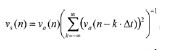
[00023] De acordo com um outro aspecto da invenção, o sistema ainda compreende uma unidade de contração que realiza, por exemplo, uma conversão de taxa do sinal de saída pela ordem de transposição T, desse modo se produzindo um sinal de saída transposto. Pela seleção do passo de síntese para ser T vezes o passo de análise, um sinal de saída distendido no tempo pode ser obtido, conforme destacado acima. Se a taxa de amostragem do sinal distendido no tempo for aumentada por um fator T ou se o sinal distendido no tempo for de amostragem reduzida por um fator T, um sinal de saída transposto poderá ser gerado, que corresponde ao sinal de entrada, deslocado na frequência pelo fator de transposição T. A operação de redução de amostragem pode compreender a etapa de seleção de apenas um subconjunto de amostras do sinal de saída. Tipicamente, apenas toda T-ésima amostra do sinal de saída é retida. Alternativamente, a taxa de amostragem pode ser aumentada por um fator T, isto é, a taxa de amostragem é interpretada como sendo T vezes mais alta. Em outras palavras, uma reamostragem ou uma conversão de taxa de amostragem significa que a taxa de amostragem é mudada, para um valor mais alto ou mais baixo. Uma redução de amostragem significa uma conversão de taxa para um valor mais baixo.[00023] According to another aspect of the invention, the system further comprises a contraction unit which performs, for example, a rate conversion of the output signal by the transposition order T, thereby producing a transposed output signal. By selecting the synthesis step to be T times the analysis step, a time-extended output signal can be obtained, as highlighted above. If the sampling rate of the time-extended signal is increased by a T-factor or if the time-extended signal is sampled by a T-factor, a transposed output signal can be generated, which corresponds to the input signal, shifted in the frequency by the transposition factor T. The sampling reduction operation can comprise the step of selecting only a subset of samples of the output signal. Typically, only the entire T-th sample of the output signal is retained. Alternatively, the sample rate can be increased by a T factor, that is, the sample rate is interpreted as being T times higher. In other words, a resampling or sample rate conversion means that the sample rate is changed to a higher or lower value. A sampling reduction means a rate conversion to a lower value.
[00024] De acordo com um outro aspecto da invenção, o sistema pode gerar um segundo sinal de saída a partir do sinal de entrada. O sistema pode compreender uma segunda unidade de processamento não linear alterando a fase dos coeficientes complexos pelo uso de um segundo fator de transposição T2 e uma segunda unidade de passo de síntese deslocando a janela de síntese e/ou os quadros do segundo sinal de saída por um segundo passo de síntese. A alteração da fase pode compreender a multiplicação da fase por um fator T2. Pela alteração da fase dos coeficientes complexos usando-se 0 segundo fator de transposição e pela transformação dos segundos coeficientes alterados em M segundas amostras alteradas e pela aplicação da janela de síntese, os quadros do segundo sinal de saída podem ser gerados a partir de um quadro do sinal de entrada. Pela aplicação do segundo passo de síntese à sequência de quadros do segundo sinal de saída, 0 segundo sinal de saída poderá ser gerado na unidade de superposição - adição.[00024] According to another aspect of the invention, the system can generate a second output signal from the input signal. The system can comprise a second non-linear processing unit by changing the phase of the complex coefficients by using a second transposition factor T2 and a second synthesis step unit by moving the synthesis window and / or the frames of the second output signal by a second synthesis step. The phase change may include the multiplication of the phase by a factor T2. By changing the phase of the complex coefficients using the second transposition factor and by transforming the second altered coefficients into M second altered samples and by applying the synthesis window, the frames of the second output signal can be generated from a frame of the input signal. By applying the second synthesis step to the frame sequence of the second output signal, the second output signal can be generated in the superposition - addition unit.
[00025] O segundo sinal de saída pode ser contraído na segunda unidade de contração que realiza, por exemplo, uma conversão de taxa do segundo sinal de saída pela segunda ordem de transposição T2. Isto produz um segundo sinal de saída transposto. Em resumo, um primeiro sinal de saída transposto pode ser gerado usando-se 0 primeiro fator de transposição T e um segundo sinal de saída transposto pode ser gerado usando-se 0 segundo fator de transposição T2. Estes dois sinais de saída transpostos então podem ser fundidos em uma unidade de combinação para a produção do sinal de saída transposto geral. A operação de fusão pode compreender a adição dos dois sinais de saída transpostos. Essa geração e a combinação de uma pluralidade de sinais de saída transpostos podem ser benéficas para a obtenção de boas aproximações do componente de sinal de frequência alta, a qual é para ser sintetizada. Deve ser notado que qualquer número de sinais de saída transpostos pode ser gerado usando-se uma pluralidade de ordens de transposição. Esta pluralidade de sinais de saída transpostos pode ser fundida, então, por exemplo, adicionada em uma unidade de combinação para a produção de um sinal de saída transposto geral.[00025] The second output signal can be contracted in the second contraction unit that performs, for example, a rate conversion of the second output signal by the second transposition order T2. This produces a second transposed output signal. In summary, a first transposed output signal can be generated using the first transposing factor T and a second transposed output signal can be generated using the second transposing factor T2. These two transposed output signals can then be merged into a combination unit to produce the general transposed output signal. The fusion operation may comprise the addition of the two transposed output signals. This generation and the combination of a plurality of transposed output signals can be beneficial for obtaining good approximations of the high frequency signal component, which is to be synthesized. It should be noted that any number of transposed output signals can be generated using a plurality of transposition orders. This plurality of transposed output signals can be merged, then, for example, added in a combination unit for the production of a general transposed output signal.
[00026] Pode ser benéfico que a unidade de combinação atribua pesos aos primeiro e segundo sinais de saída transpostos, antes da fusão. A atribuição de peso pode ser realizada de modo que a energia ou a energia por largura de banda dos primeiro e segundo sinais de saída transpostos corresponda à energia ou à energia por largura de banda do sinal de saída, respectivamente.[00026] It may be beneficial for the combining unit to assign weights to the first and second output signals transposed, prior to the merger. The weight assignment can be performed so that the energy or energy per bandwidth of the first and second output signals transposed corresponds to the energy or energy per bandwidth of the output signal, respectively.
[00027] De acordo com um aspecto adicional da invenção, o sistema pode compreender uma unidade de alinhamento a qual aplica um desvio no tempo aos primeiro e segundo sinais de saída transpostos, antes da entrada na unidade de combinação. Esse desvio no tempo pode compreender o deslocamento dos dois sinais de saída transpostos com respeito a cada outro no domínio de tempo. O desvio no tempo pode ser uma função da ordem de transposição e/ou do comprimento das janelas. Em particular, o desvio no tempo pode ser determinado como (T - 2)L/4.[00027] In accordance with a further aspect of the invention, the system may comprise an alignment unit which applies a time shift to the first and second output signals transposed, before entering the combining unit. This time deviation may comprise the displacement of the two output signals transposed with respect to each other in the time domain. The deviation in time can be a function of the order of transposition and / or the length of the windows. In particular, the time deviation can be determined as (T - 2) L / 4.
[00028] De acordo com um outro aspecto da invenção, o sistema de transposição descrito acima pode ser embutido em um sistema para a decodificação de um sinal de multimídia recebido compreendendo um sinal de áudio. O sistema de decodificação pode compreender uma unidade de transposição a qual corresponde ao sistema destacado acima, onde o sinal de entrada tipicamente é um componente de frequência baixa do sinal de áudio e o sinal de saída é um componente de frequência alta do sinal de áudio. Em outras palavras, o sinal de entrada tipicamente é um sinal de passa baixa com uma certa largura de banda e o sinal de saída é um sinal de passa banda de uma largura de banda tipicamente mais alta. Mais ainda, ele pode compreender um decodificador de núcleo para a decodificação do componente de frequência baixa do sinal de áudio a partir do fluxo de bit recebido. Esse decodificador de núcleo pode ser com base em um esquema de codificação, tal como Dolby E, Dolby Digital ou AAC. Em particular, esse sistema de decodificação pode ser uma caixa adaptadora para a decodificação de um sinal de multimídia recebido compreendendo um sinal de áudio e outros sinais, tal como de vídeo.[00028] According to another aspect of the invention, the transposition system described above can be embedded in a system for decoding a received multimedia signal comprising an audio signal. The decoding system may comprise a transposition unit which corresponds to the system highlighted above, where the input signal is typically a low frequency component of the audio signal and the output signal is a high frequency component of the audio signal. In other words, the input signal is typically a low-pass signal with a certain bandwidth and the output signal is a typically high-bandwidth pass signal. Furthermore, it may comprise a core decoder for decoding the low frequency component of the audio signal from the received bit stream. This core decoder can be based on an encoding scheme, such as Dolby E, Dolby Digital or AAC. In particular, such a decoding system may be an adapter box for decoding a received multimedia signal comprising an audio signal and other signals, such as a video signal.
[00029] Deve ser notado que a presente invenção também descreve um método para a transposição de um sinal de entrada por um fator de transposição T. O método corresponde ao sistema destacado acima e pode compreender qualquer combinação dos aspectos mencionados acima. Ele pode compreender as etapas de extração de amostras do sinal de entrada usando-se uma janela de análise de comprimento L, e de seleção de um fator de sobreamostragem F como uma função do fator de transposição T. Ele ainda pode compreender as etapas de transformação das amostras L do domínio de tempo para o domínio de frequência produzindo coeficientes complexos F * L, e de alteração dos coeficientes complexos com o fator de transposição T. Em etapas adicionais, o método pode transformar os coeficientes complexos F * L alterados no domínio de tempo produzindo as F * amostras L alteradas, e pode gerar o sinal de saída usando uma janela de síntese de comprimento L. Deve ser notado que o método também pode ser adaptado para os comprimentos gerais da janela de análise e de síntese, isto é, para La e Ls gerais, conforme destacado acima.[00029] It should be noted that the present invention also describes a method for transposing an input signal by a transposition factor T. The method corresponds to the system highlighted above and can comprise any combination of the aspects mentioned above. He can understand the steps of extracting samples from the input signal using a length analysis window L, and selecting an oversampling factor F as a function of the transposition factor T. He can still understand the transformation steps of samples L of the time domain to the frequency domain producing complex F * L coefficients, and of alteration of the complex coefficients with the transposition factor T. In additional steps, the method can transform the altered F * L complex coefficients in the domain of time producing the altered F * L samples, and can generate the output signal using a synthesis window of length L. It should be noted that the method can also be adapted to the overall lengths of the analysis and synthesis window, that is, for general La and Ls, as highlighted above.
[00030] De acordo com um outro aspecto da invenção, o método pode compreender as etapas de deslocamento da janela de análise por um passo de análise de Sa amostras ao longo do sinal de entrada, e/ou pelo deslocamento da janela de síntese e/ou dos quadros do sinal de saída por um passo de síntese de Ss amostras. Pela seleção do passo de análise para ser T vezes o passo de análise, o sinal de saída pode ser distendido no tempo com respeito ao sinal de entrada por um fator T. Quando da execução de uma etapa adicional de realização de uma conversão de taxa do sinal de saída pela ordem de transposição T, um sinal de saída transposto pode ser obtido. Esse sinal de saída transposto pode compreender componentes de frequência que são deslocadas para cima por um fator T com respeito às componentes de frequência correspondentes do sinal de entrada.[00030] According to another aspect of the invention, the method can comprise the steps of shifting the analysis window by a step of analyzing Sa samples along the input signal, and / or by shifting the synthesis window and / or the frames of the output signal by a synthesis step of Ss samples. By selecting the analysis step to be T times the analysis step, the output signal can be extended in time with respect to the input signal by a T factor. When performing an additional step of carrying out a rate conversion of the output signal in order of transposition T, a transposed output signal can be obtained. This transposed output signal may comprise frequency components that are shifted upward by a T factor with respect to the corresponding frequency components of the input signal.
[00031] O método ainda pode compreender as etapas para a geração de um segundo sinal de saída. Isto pode ser implementado pela alteração da fase dos coeficientes complexos pelo uso de um segundo fator de transposição T2, pelo deslocamento da janela de síntese e/ou dos quadros do segundo sinal de saída por um segundo passo de síntese, um segundo sinal de saída pode ser gerado usando-se 0 segundo fator de transposição T2 e o segundo passo de síntese. Pela realização de uma conversão de taxa do segundo sinal de saída pela segunda ordem de transposição T2, um segundo sinal de saída transposto pode ser gerado. Eventualmente, pela fusão dos primeiro e segundo sinais de saída transpostos, um sinal de saída transposto fundido ou geral incluindo as componentes de sinal de frequência alta geradas por duas ou mais transposições com diferentes fatores de transposição pode ser obtido.[00031] The method can still comprise the steps for generating a second output signal. This can be implemented by changing the phase of the complex coefficients by using a second transposition factor T2, by moving the synthesis window and / or the frames of the second output signal by a second synthesis step, a second output signal can be generated using the second transposition factor T2 and the second synthesis step. By performing a rate conversion of the second output signal by the second transposition order T2, a second transposed output signal can be generated. Eventually, by merging the first and second transposed output signals, a fused or general transposed output signal including the high frequency signal components generated by two or more transpositions with different transposition factors can be obtained.
[00032] De acordo com outros aspectos da invenção, a invenção descreve um programa de software adaptado para execução em um processador e para a realização das etapas de método da presente invenção, quando realizadas em um dispositivo de computação. A invenção também descreve um meio de armazenamento que compreende um programa de software adaptado para execução em um processador e para a realização das etapas de método da invenção, quando realizadas em um dispositivo de computação. Mais ainda, a invenção descreve um produto de programa de computador que compreende instruções executáveis para a realização do método da invenção, quando executado em um computador.[00032] In accordance with other aspects of the invention, the invention describes a software program adapted for execution on a processor and for carrying out the method steps of the present invention, when performed on a computing device. The invention also describes a storage medium that comprises a software program adapted for execution on a processor and for carrying out the method steps of the invention, when performed on a computing device. Furthermore, the invention describes a computer program product that comprises executable instructions for carrying out the method of the invention, when executed on a computer.
[00033] De acordo com um outro aspecto, um outro método e um sistema para a transposição de um sinal de entrada por um fator de transposição T são descritos. Este método e o sistema podem ser usados independentemente ou em combinação com os métodos e sistemas destacados acima. Qualquer um dos recursos destacados no presente documento pode ser aplicado a este método / sistema e vice- versa.[00033] According to another aspect, another method and system for the transposition of an input signal by a transposition factor T are described. This method and the system can be used independently or in combination with the methods and systems highlighted above. Any of the features highlighted in this document can be applied to this method / system and vice versa.
[00034] O método pode compreender a etapa de extração de um quadro de amostras do sinal de entrada usando-se uma janela de análise de comprimento L. Então, o quadro do sinal de entrada pode ser transformado a partir do domínio de tempo para o domínio de frequência produzindo M coeficientes complexos. A fase dos coeficientes complexos pode ser alterada com o fator de transposição T e os M coeficientes complexos alterados podem ser transformados no domínio de tempo, produzindo M amostras alteradas. Eventualmente, um quadro de um sinal de saída pode ser gerado usando-se uma janela de síntese de comprimento L. O método e o sistema podem usar uma janela de análise e uma janela de síntese, as quais são diferentes de cada outra. A janela de análise e a de síntese podem ser diferentes com respeito ao seu formato, seu comprimento, ao número de coeficientes definindo as janelas e/ou os valores dos coeficientes definindo as janelas. Ao se fazer isto, graus adicionais de liberdade na seleção das janelas de análise e de síntese podem ser obtidos, de modo que uma descontinuidade do sinal de saída transposto possa ser reduzida ou removida.[00034] The method can comprise the step of extracting a sample frame from the input signal using an L-length analysis window. Then, the input signal frame can be transformed from the time domain to the frequency domain producing M complex coefficients. The phase of the complex coefficients can be changed with the transposition factor T and the altered M complex coefficients can be transformed in the time domain, producing M altered samples. Eventually, a frame of an output signal can be generated using a synthesis window of length L. The method and the system can use an analysis window and a synthesis window, which are different from each other. The analysis window and the synthesis window can be different with respect to their format, their length, the number of coefficients defining the windows and / or the values of the coefficients defining the windows. By doing this, additional degrees of freedom in the selection of the analysis and synthesis windows can be obtained, so that a discontinuity of the transposed output signal can be reduced or removed.
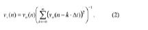
[00035] De acordo com um outro aspecto, a janela de análise e a janela de síntese são biortogonais uma com respeito à outra. A janela de síntese vs(n) pode ser dada por:
[00036] O passo de tempo da janela de síntese Δtstipicamente corresponde ao passo de síntese Ss.[00036] The synthesis window time step Δtstypically corresponds to the synthesis step Ss.
[00037] De acordo com um aspecto adicional, a janela de análise pode ser selecionada de modo que sua transformada z tenha zeros duplos no círculo unitário. Preferencialmente, a transformada z da janela de análise apenas tem zeros duplos no círculo unitário. A título de exemplo, a janela de análise pode ser uma janela de seno ao quadrado. Em um outro exemplo, a janela de análise de comprimento L pode ser determinada pela convolução de duas janelas de seno de comprimento L, produzindo-se uma janela de seno ao quadrado de comprimento 2L- 1. Em uma etapa adicional, um zero é anexado à janela de seno ao quadrado, produzindo-se uma janela de base de comprimento 2L. Eventualmente, a janela de base pode ser reamostrada usando-se interpolação linear, desse modo se produzindo uma janela simétrica par de comprimento L como a janela de análise.[00037] According to an additional aspect, the analysis window can be selected so that its z transform has double zeros in the unit circle. Preferably, the z transform of the analysis window only has double zeros in the unit circle. For example, the analysis window can be a square sine window. In another example, the analysis window of length L can be determined by the convolution of two sine windows of length L, producing a square sine window of length 2L- 1. In an additional step, a zero is attached to the square sine window, producing a base window of length 2L. Eventually, the base window can be resampled using linear interpolation, thereby producing an even symmetric window of length L as the analysis window.
[00038] Os métodos e sistemas descritos no presente documento podem ser implementados como um software, um firmware e/ou um hardware. Certos componentes podem ser implementados, por exemplo, como um software rodando em um processador de sinal digital ou um microprocessador. Outros componentes podem ser implementados, por exemplo, como um hardware ou como circuitos integrados específicos de aplicação. Os sinais encontrados nos métodos e sistemas descritos podem ser armazenados em meios, tais como uma memória de acesso randômico ou meios de armazenamento óticos. Eles podem ser transferidos através de redes, tais como redes de rádio, redes por satélite, redes sem fio ou redes com fio, por exemplo, a internet. Os dispositivos típicos que fazem uso do método e do sistema descritos no presente documento são caixas adaptadoras ou outro equipamento de instalações prediais de consumidor, os quais decodifiquem sinais de áudio. No lado de codificação, o método e o sistema podem ser usados em estações de difusão, por exemplo, sistemas de extremidade de entrada de vídeo ou TV.[00038] The methods and systems described in this document can be implemented as software, firmware and / or hardware. Certain components can be implemented, for example, as software running on a digital signal processor or a microprocessor. Other components can be implemented, for example, as hardware or as application specific integrated circuits. The signals found in the described methods and systems can be stored on media, such as a random access memory or optical storage media. They can be transferred over networks, such as radio networks, satellite networks, wireless networks or wired networks, for example, the internet. Typical devices that make use of the method and system described in this document are adapter boxes or other equipment from consumer building installations, which decode audio signals. On the coding side, the method and system can be used on broadcast stations, for example, video input or TV end systems.
[00039] Deve ser notado que as modalidades e os aspectos da invenção descritos aqui neste documento podem ser combinados arbitrariamente. Em particular, deve ser notado que os aspectos destacados para o sistema também são aplicáveis ao método correspondente englobado pela presente invenção. Mais ainda, deve ser notado que a exposição da invenção também cobre outras combinações de concretização além das combinações de concretização as quais são explicitamente dadas pelas referências prévias nas concretizações, isto é, as concretizações e suas características técnicas podem ser combinadas em qualquer ordem e qualquer formação.[00039] It should be noted that the modalities and aspects of the invention described here in this document can be combined arbitrarily. In particular, it should be noted that the aspects highlighted for the system are also applicable to the corresponding method encompassed by the present invention. Furthermore, it should be noted that the presentation of the invention also covers other combinations of embodiments in addition to the combinations of embodiments which are explicitly given by the previous references in the embodiments, that is, the embodiments and their technical characteristics can be combined in any order and any formation.
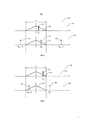
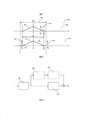
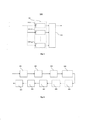
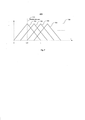
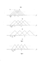
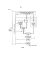
[00040] A presente invenção será descrita, agora, a título de exemplos ilustrativos, não limitando o escopo ou o espírito da invenção, com referência aos desenhos associados, nos quais: a figura 1 ilustra um Dirac em uma posição em particular conforme aparece nas janelas de análise e de síntese de um transpositor harmônico; a figura 2 ilustra um Dirac em uma posição diferente, conforme aparece nas janelas de análise e de síntese de um transpositor harmônico; a figura 3 ilustra um Dirac para a posição da figura 2, conforme ele aparece de acordo com a presente invenção; a figura 4 ilustra a operação de um decodificador de áudio melhorado de HFR; a figura 5 ilustra a operação de um transpositor harmônico usando várias ordens; a figura 6 ilustra a operação de um transpositor harmônico de domínio de frequência (FD); a figura 7 mostra uma sucessão de janela de análise e de síntese; a figura 8 ilustra janelas de análise e de síntese em passos diferentes; a figura 9 ilustra o efeito de reamostragem do passo de síntese de janelas; as figura 10 e 11 ilustram modalidades de um codificador e de um decodificador, respectivamente, usando os esquemas de transposição harmônica destacados no presente documento; e a figura 12 ilustra uma modalidade de uma unidade de transposição mostrada nas figuras 10 e 11.[00040] The present invention will now be described by way of illustrative examples, without limiting the scope or spirit of the invention, with reference to the associated drawings, in which: Figure 1 illustrates a Dirac in a particular position as it appears in the analysis and synthesis windows of a harmonic transpositor; figure 2 illustrates a Dirac in a different position, as it appears in the analysis and synthesis windows of a harmonic transpositor; figure 3 illustrates a Dirac for the position of figure 2, as it appears in accordance with the present invention; Figure 4 illustrates the operation of an improved HFR audio decoder; figure 5 illustrates the operation of a harmonic transposer using several orders; figure 6 illustrates the operation of a frequency domain harmonic (FD) transponder; figure 7 shows a succession of analysis and synthesis windows; figure 8 shows analysis and synthesis windows in different steps; figure 9 illustrates the resampling effect of the window synthesis step; figures 10 and 11 illustrate modalities of an encoder and a decoder, respectively, using the harmonic transposition schemes highlighted in this document; and figure 12 illustrates an embodiment of a transposition unit shown in figures 10 and 11.
[00041] As modalidades descritas abaixo são meramente ilustrativas para os princípios da presente invenção para uma Transposição Harmônica Melhorada. É entendido que modificações e variações dos arranjos e detalhes descritos aqui serão evidentes para outros versados na técnica. Portanto, há a intenção de ser limitado apenas pelo escopo das concretizações de patente iminentes e não pelos detalhes específicos apresentados a título de descrição e de explicação das modalidades aqui.[00041] The modalities described below are merely illustrative for the principles of the present invention for Enhanced Harmonic Transposition. It is understood that modifications and variations of the arrangements and details described here will be evident to others skilled in the art. Therefore, it is intended to be limited only by the scope of the impending patent embodiments and not by the specific details presented by way of description and explanation of the modalities here.
[00042] A seguir, os princípios de transposição harmônica no domínio de frequência e os melhoramentos propostos conforme ensinado pela presente invenção são destacados. Um componente- chave da transposição harmônica é uma distensão de tempo por um fator de transposição T inteiro, o que preserva a frequência de senoides. Em outras palavras, a transposição harmônica é baseada na distensão no tempo do sinal subjacente pelo fator T. A distensão no tempo é realizada de modo que as frequências de senoides, as quais compõem o sinal de entrada sejam mantidas. Essa distensão no tempo pode ser realizada usando-se um codificador de voz de fase. O codificador de voz de fase é baseado em uma representação de domínio de frequência fornecida por um banco de filtro de DFT em janela com uma janela de análise va(n) e uma janela de síntese vs(n). Essa transformada de análise / síntese também é referida como uma Transformada de Fourier de tempo curto (STFT).[00042] Next, the principles of harmonic transposition in the frequency domain and the proposed improvements as taught by the present invention are highlighted. A key component of harmonic transposition is a lengthening of time by an entire transposition factor T, which preserves the frequency of sinusoidal transitions. In other words, the harmonic transposition is based on the time strain of the underlying signal by the T factor. The time strain is performed so that the sinusoidal frequencies, which make up the input signal, are maintained. This time extension can be accomplished using a phase speech encoder. The phase speech encoder is based on a frequency domain representation provided by a window DFT filter bank with an analysis window va (n) and a synthesis window vs (n). This analysis / synthesis transform is also referred to as a short time Fourier Transform (STFT).
[00043] Uma transformada de Fourier de tempo curto é realizada em um sinal de entrada de domínio de tempo para a obtenção de uma sucessão de quadros espectrais sobrepostos. De modo a se minimizarem possíveis efeitos de banda lateral, janelas apropriadas de análise / síntese, por exemplo, janelas gaussianas, janelas de cosseno, janelas de Hamming, janelas de Hann, janelas retangulares, janelas de Bartlett, janelas de Blackman e outras devem ser selecionadas. O atraso de tempo no qual todo quadro espectral é capturado a partir do sinal de entrada é referido como o tamanho de salto ou passo. A STFT do sinal de entrada é referida como o estágio de análise e leva a uma representação de domínio de frequência do sinal de entrada. A representação de domínio de frequência compreende uma pluralidade de sinais de sub-banda, onde cada sinal de sub-banda representa um certo componente de frequência do sinal de entrada.[00043] A short time Fourier transform is performed on a time domain input signal to obtain a succession of overlapping spectral frames. In order to minimize possible side band effects, appropriate analysis / synthesis windows, for example, Gaussian windows, cosine windows, Hamming windows, Hann windows, rectangular windows, Bartlett windows, Blackman windows and others should be selected. The time delay in which every spectral frame is captured from the input signal is referred to as the hop or step size. The STFT of the input signal is referred to as the analysis stage and leads to a frequency domain representation of the input signal. The frequency domain representation comprises a plurality of subband signals, where each subband signal represents a certain frequency component of the input signal.
[00044] A representação de domínio de frequência do sinal de entrada então pode ser processada de uma forma desejada. Para fins de distensão de tempo do sinal de entrada, cada sinal de sub-banda pode ser distendido no tempo, por exemplo, por um atraso das amostras de sinal de sub-banda. Isto pode ser obtido pelo uso de um tamanho de salto de síntese, o qual é maior do que o tamanho de salto de análise. O sinal de domínio de tempo pode ser reconstruído pela realização de uma transformada de Fourier (rápida) inversa em todos os quadros, seguida por uma acumulação sucessiva dos quadros. Esta operação do estágio de síntese é referida como uma operação de superposição - adição. O sinal de saída resultante é uma versão distendida no tempo do sinal de entrada compreendendo as mesmas componentes de frequência que o sinal de entrada. Em outras palavras, o sinal de saída resultante tem a mesma composição espectral que o sinal de entrada, mas é mais lento do que o sinal de entrada, isto é, sua progressão é distendida no tempo.[00044] The frequency domain representation of the input signal can then be processed in a desired manner. For the purpose of time extension of the input signal, each subband signal can be extended in time, for example, by a delay of the subband signal samples. This can be achieved by using a synthesis hop size, which is larger than the analysis hop size. The time domain signal can be reconstructed by performing an inverse (fast) Fourier transform on all frames, followed by a successive accumulation of the frames. This synthesis stage operation is referred to as a superposition - addition operation. The resulting output signal is a time-extended version of the input signal comprising the same frequency components as the input signal. In other words, the resulting output signal has the same spectral composition as the input signal, but is slower than the input signal, that is, its progression is stretched over time.
[00045] A transposição para frequências mais altas então pode ser obtida subsequentemente, ou de uma maneira integrada, através de uma redução da amostragem dos sinais distendidos. Como resultado, o sinal transposto tem a extensão no tempo do sinal inicial, mas compreende componentes de frequência os quais são deslocados para cima por um fator de transposição predefinido.[00045] Transposition to higher frequencies can then be achieved subsequently, or in an integrated manner, by reducing the sampling of the extended signals. As a result, the transposed signal has the time span of the initial signal, but comprises frequency components which are shifted upwards by a predefined transposition factor.
[00046] Em termos matemáticos, o codificador de voz de fase pode ser descrito conforme se segue. Um sinal de entrada x(t) é amostrado a uma taxa de amostragem R para a produção do sinal de entrada discreto x(n). Durante o estágio de análise, uma STFT é determinada para o sinal de entrada x(n) em instantes de tempo de análise em particular para valores sucessivos tak. Os instantes de tempo de análise preferencialmente são selecionados uniformemente através de * Aí '
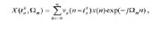
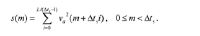
[00047] O estágio de síntese pode ser realizado nos instantes de tempo de síntese tak , os quais de forma típica sao uniformemente distribuídos de acordo com , tak=k Δl1 onde Δtsé o fator de salto de síntese ou o passo de síntese. Em cada um destes instantes de tempo de síntese, um sinal de tempo curto yk(n) é obtido por uma transformação inversa de Fourier do sinal de sub-banda de STFT )Ωnr) o qual pode ser idêntico a nos instantes de tempo de síntese ’. Contudo, tipicamente, os sinais de sub-banda de STFT são modificados, por exemplo, distendidos no tempo e/ou de fase modulada, e/ou de amplitude modulada, de modo que o sinal de sub- banda de análise J difira do sinal de sub-banda de síntese Em uma modalidade preferida, os sinais de sub-banda de STFT são de fase modulada, isto é, a fase dos sinais de sub-banda de STFT é modificada. O sinal de síntese de termo curto yk(n) pode ser denotado como:
[00048] O sinal de síntese de termo curto yk(n) pode ser visto como um componente do sinal de saída geral y(n) compreendendo os sinais Y(tkΩ 1 de sub-banda de síntese para m = 0,..., M - 1, no instante de tempo de síntese . Isto é, o sinal de termo curto yk(n) e a DFT inversa para um quadro de sinal específico. O sinal de saída geral y(n) pode ser obtido pela superposição e pela adição de sinais de tempo curto em ik janela yk(n) em todos os instantes de tempo de síntese 5. Isto é, o sinal de saída y(n) pode ser denotado como: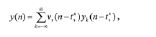
[00049] A seguir, a implementação de distensão no tempo no domínio de frequência é destacada. Um ponto de começo adequado de modo a se descreverem os aspectos do distensor no tempo é considerar o caso em que T = 1, isto é, o caso em que o fator de transposição T equivale a 1 e onde nenhuma distensão ocorre. Assumindo que o passo de tempo de análise Δtae o passo de tempo de síntese Δtsdo banco de filtro de DFT sejam iguais, isto é, Δta= Δts= Δt, o efeito combinado de análise seguida pela síntese é aquele de uma modulação de amplitude com uma função periódica em Δt: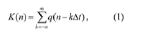
[00050] Para T > 1, isto é, para um fator de transposição maior do que 1, uma distensão de tempo pode ser obtida pela realização da análise no passo Δta= Δt/T, ao passo que o passo de síntese é mantida em Δta= Δt. Em outras palavras, uma distensão de tempo por um fator T pode ser obtida pela aplicação de um fator de salto ou um passo no estágio de síntese. Conforme pode ser visto a partir das fórmulas providas acima, o uso de um passo de síntese a qual é T vezes maior do que o passo de análise deslocará os sinais de síntese de termo curto yk(n) por intervalos T vezes maiores na operação de superposição - adição. Isto eventualmente resultará em uma distensão no tempo do sinal de saída y(n).[00050] For T> 1, that is, for a transposition factor greater than 1, a time extension can be obtained by performing the analysis in the step Δta = Δt / T, whereas the synthesis step is maintained in Δta = Δt. In other words, a time extension by a T factor can be obtained by applying a jump factor or a step in the synthesis stage. As can be seen from the formulas provided above, the use of a synthesis step which is T times greater than the analysis step will shift the short term synthesis signals yk (n) by intervals T times greater in the operation of overlay - addition. This will eventually result in a time extension of the output signal y (n).
[00051] Deve ser notado que a distensão no tempo pelo fator T pode envolver, adicionalmente, uma multiplicação de fase por um fator T entre a análise e a síntese. Em outras palavras, uma distensão no tempo por um fator T envolve uma multiplicação de fase por um fator T dos sinais de sub-banda.[00051] It should be noted that the strain in time by factor T may additionally involve a multiplication of phase by factor T between analysis and synthesis. In other words, a time extension by a T factor involves a phase multiplication by a T factor of the subband signals.
[00052] A seguir, é destacado como a operação de distensão no tempo descrita acima pode ser traduzida em uma operação de transposição harmônica. A modificação de escala de passo ou transposição harmônica pode ser obtida pela realização de uma conversão de taxa de amostra do sinal de saída distendido no tempo y(n). Para a realização de uma transposição harmônica por um fator T, um sinal de saída y(n) o qual é uma versão distendida no tempo pelo fator T do sinal de entrada x(n) pode ser obtido usando-se o método de codificação de voz de fase descrito acima. A transposição harmônica então pode ser obtida pela redução da amostragem do sinal de saída y(n) por um fator T ou pela conversão da taxa de amostragem de R para TR. Em outras palavras, em vez de interpretar o sinal de saída y(n) como tendo a mesma taxa de amostragem que o sinal de entrada x(n), mas de duração de T vezes, o sinal de saída y(n) pode ser interpretado como sendo da mesma duração, mas de T vezes a taxa de amostragem. A redução de amostragem subsequente de T então pode ser interpretada como tornando a taxa de amostragem de saída igual à taxa de amostragem de entrada, de modo que os sinais eventualmente possam ser adicionados. Durante estas operações, deve-se ter cuidado quando da redução da amostragem do sinal transposto, de modo que nenhuma descontinuidade ocorra.[00052] Next, it is highlighted how the time stretching operation described above can be translated into a harmonic transposition operation. The modification of the step scale or harmonic transposition can be obtained by performing a sample rate conversion of the output signal extended in time y (n). For a harmonic transposition by a factor T, an output signal y (n) which is a time-extended version by the factor T of the input signal x (n) can be obtained using the phase voice described above. Harmonic transposition can then be achieved by reducing the sampling of the output signal y (n) by a factor T or by converting the sample rate from R to TR. In other words, instead of interpreting the output signal y (n) as having the same sample rate as the input signal x (n), but of duration T times, the output signal y (n) can be interpreted as being of the same duration, but T times the sampling rate. The subsequent sampling reduction of T can then be interpreted as making the output sampling rate equal to the input sampling rate, so that signals can eventually be added. During these operations, care must be taken when reducing the sampling of the transposed signal, so that no discontinuity occurs.
[00053] Assumindo que o sinal de entrada x(n) seja uma senoide e quando se assume uma janela de análise simétrica va(n), o método de distensão no tempo com base no codificador de voz de fase descrito acima funcionará perfeitamente para valores ímpares de T, e resultará em uma versão distendida no tempo do sinal de entrada x(n) tendo a mesma frequência. Em combinação com uma redução de amostragem subsequente, uma senoide y(n) com uma frequência a qual é T vezes a frequência do sinal de entrada x(n) será obtida.[00053] Assuming that the input signal x (n) is a sinusoid and when assuming a symmetric analysis window va (n), the time strain method based on the phase speech encoder described above will work perfectly for values odd numbers of T, and will result in a time-extended version of the input signal x (n) having the same frequency. In combination with a subsequent sampling reduction, a sinusoid y (n) with a frequency which is T times the frequency of the input signal x (n) will be obtained.
[00054] Para valores pares de T, o método de distensão no tempo / transposição harmônica destacado acima será mais aproximado, uma vez que lobos laterais de valor negativo da resposta de frequência da janela de análise va(n) serão reproduzidos com fidelidade diferente pela multiplicação de fase. Os lobos de lado negativo tipicamente vêm do fato de que a maioria das janelas práticas (ou filtros de protótipo) tem numerosos zeros discretos localizados no círculo unitário, resultando em deslocamentos de fase de 180 graus. Quando da multiplicação dos ângulos de fase usando fatores de transposição pares, os deslocamentos de fase tipicamente serão transladados para 0 (em vez de múltiplos de 360) grau, dependendo do fator de transposição usado. Em outras palavras, quando se usam fatores de transposição pares, os deslocamentos de fase se anulam. Isto tipicamente dará origem a uma descontinuidade no sinal de saída transposto y(n). Um cenário particularmente desvantajoso pode surgir quando uma senoide estiver localizada em uma frequência correspondente ao topo do primeiro lobo lateral do filtro de análise. Dependendo da rejeição deste lobo na resposta de magnitude, a descontinuidade será mais ou menos audível no sinal de saída. Deve ser notado que, para fatores pares T, uma diminuição no passo geral Δt tipicamente melhora o desempenho do distensor no tempo à custa de uma complexidade computacional mais alta.[00054] For even values of T, the time distension / harmonic transposition method highlighted above will be more approximate, since the negative lobes of the frequency response of the analysis window va (n) will be reproduced with different fidelity by phase multiplication. The negative side wolves typically come from the fact that most practical windows (or prototype filters) have numerous discrete zeros located in the unit circle, resulting in 180 degree phase shifts. When multiplying the phase angles using even transposition factors, the phase shifts will typically be translated to 0 (instead of multiples of 360) degrees, depending on the transposition factor used. In other words, when using even transposition factors, the phase shifts are canceled out. This will typically give rise to a discontinuity in the transposed output signal y (n). A particularly disadvantageous scenario can arise when a sinusoid is located at a frequency corresponding to the top of the first lateral lobe of the analysis filter. Depending on the rejection of this lobe in the magnitude response, the discontinuity will be more or less audible in the output signal. It should be noted that, for even factors T, a decrease in the general step Δt typically improves the performance of the stiffener over time at the expense of higher computational complexity.
[00055] Na EP0940015B1 / no WO09/57436 intitulado "Source coding enhancement using spectral band replication", o qual é incorporado como referência, foi descrito um método sobre como se evitar que uma descontinuidade emerja de um transpositor harmônico, quando se usarem fatores de transposição pares. Este método, denominado travamento de fase relativa, avalia a diferença de fase relativa entre canais adjacentes, e determina se uma senoide é de fase invertida em qualquer canal. A detecção é realizada pelo uso da equação (32) da EP0940015B1. Os canais detectados como de fase invertida são corrigidos, após os ângulos de fase serem multiplicados pelo fator de transposição real.[00055] In EP0940015B1 / no WO09 / 57436 entitled "Source coding enhancement using spectral band replication", which is incorporated as a reference, a method has been described on how to prevent a discontinuity from emerging from a harmonic transponder, when using factors of transposing pairs. This method, called relative phase locking, evaluates the relative phase difference between adjacent channels, and determines whether a sinusoid is inverted in any channel. Detection is performed using the equation (32) of EP0940015B1. The channels detected as inverted phase are corrected, after the phase angles are multiplied by the real transposition factor.
[00056] A seguir, um novo método para se evitar uma descontinuidade quando se usam fatores de transposição T pares e/ou ímpares é descrito. Ao contrário do método de travamento de fase relativa do EP0940015B1, este método não requer a detecção e a correção de ângulos de fase. A solução nova para o problema acima faz uso de janelas de transformada de análise e de síntese que não são idênticas. No caso de uma reconstrução perfeita (PR), isto corresponde a uma transformada / um banco de filtro biortogonal, em vez de uma transformada / um banco de filtro ortogonal.[00056] Below, a new method to avoid discontinuity when using even and / or odd T transposition factors is described. Unlike the relative phase locking method of EP0940015B1, this method does not require the detection and correction of phase angles. The new solution to the above problem makes use of analysis and synthesis transform windows that are not identical. In the case of a perfect reconstruction (PR), this corresponds to a biortogonal transform / filter bank, instead of an orthogonal transform / filter bank.
[00057] Para a obtenção de uma transformada biortogonal dada uma certa janela de análise va(n), a janela de síntese vs(n) é escolhida para seguir:
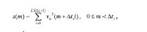
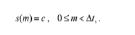
[00058] Contudo, a seguir, uma outra sequência w(n) é introduzida, onde w(n) é uma medida sobre quanto a janela de síntese vs(n) se desvia da janela de análise va(n), isto é, quanto a transformada biortogonal difere do caso ortogonal. A sequência w(n) é dada por:
[00059] A condição para uma reconstrução perfeita, então, é dada por: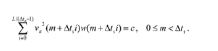
[00060] Para uma solução possível, w(n) poderia ser restrita a ser periódica com o passo de tempo de síntese Δts, isto é, w(n) = w(n + Δtsi), V i, n. Então, obtém-se: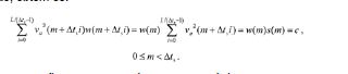
[00061] A condição na janela de síntese vs(n), daí, é: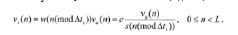
[00062] Pela derivação da janela de síntese vs(n), conforme destacado acima, uma liberdade muito maior quando do projeto da janela de análise va(n) é provida. Esta liberdade adicional pode ser usada para o projeto de um par de janelas de análise / síntese, o que não exibe uma descontinuidade do sinal transposto.[00062] By deriving the synthesis window vs (n), as highlighted above, a much greater freedom when designing the analysis window va (n) is provided. This additional freedom can be used for the design of a pair of analysis / synthesis windows, which does not exhibit a discontinuity of the transposed signal.
[00063] Para a obtenção de um par de janelas de análise / síntese que suprima uma descontinuidade para fatores de transposição pares, várias modalidades serão destacadas a seguir. De acordo com uma primeira modalidade, as janelas ou os filtros de protótipo são feitos longos o bastante para a atenuação do nível do primeiro lobo lateral na resposta de frequência abaixo de um certo nível de "descontinuidade". O passo de tempo de análise Δtaneste caso será apenas uma fração (pequena) do comprimento de janela L. Isto tipicamente resultará em um espalhamento de transientes, por exemplo, em sinais percussivos.[00063] In order to obtain a pair of analysis / synthesis windows that suppress a discontinuity for even transposition factors, several modalities will be highlighted below. According to a first modality, the windows or prototype filters are made long enough to attenuate the level of the first lateral lobe in the frequency response below a certain level of "discontinuity". The analysis time step Δ in this case will be just a (small) fraction of the L window length. This will typically result in a scattering of transients, for example, in percussive signals.
[00064] De acordo com uma segunda modalidade, a janela de análise va(n) é escolhida para ter zeros duplos no círculo unitário. A resposta de fase resultante de um zero duplo é um deslocamento de fase de 360 graus. Estes deslocamentos de fase são retidos, quando os ângulos de fase são multiplicados pelos fatores de transposição, independentemente de os fatores de transposição serem ímpares ou pares. Quando um filtro de análise apropriado e atenuado va(n), tendo zeros duplos no círculo unitário é obtido, a janela de síntese é obtida a partir das equações destacadas acima.[00064] According to a second modality, the analysis window va (n) is chosen to have double zeros in the unit circle. The phase response resulting from a double zero is a 360 degree phase shift. These phase shifts are retained when the phase angles are multiplied by the transposition factors, regardless of whether the transposition factors are odd or even. When an appropriate and attenuated analysis filter va (n), having double zeros in the unit circle is obtained, the synthesis window is obtained from the equations highlighted above.
[00065] Em um exemplo da segunda modalidade, o filtro / a janela de análise va(n) é a "janela de seno ao quadrado", isto é, a janela seno:
[00066] Em geral, foi destacado como um par de janelas de análise e de síntese pode ser selecionado de modo que uma descontinuidade no sinal de saída transposto possa ser evitada ou reduzida significativamente. O método é particularmente relevante quando se usam fatores de transposição pares.[00066] In general, it has been highlighted how a pair of analysis and synthesis windows can be selected so that a discontinuity in the transposed output signal can be avoided or significantly reduced. The method is particularly relevant when using even transposition factors.
[00067] Um outro aspecto a considerar no contexto de transpositores harmônicos é um envolvimento de fase. Deve ser notado que, ao passo que grande cuidado deve ser tomado com relação a questões de desenvolvimento em codificadores de voz de fase de finalidade geral, o transpositor harmônico tem operações de fase definidas de forma não ambígua, quando fatores de transposição inteiros T são usados. Assim, em modalidades preferidas a ordem de transposição T é um valor inteiro. Caso contrário, técnicas de desenvolvimento de fase poderiam ser aplicadas, onde um desenvolvimento de fase é um processo por meio do qual o incremento de fase entre dois quadros consecutivos é usado para a estimativa da frequência instantânea de uma quase senoide em cada canal.[00067] Another aspect to consider in the context of harmonic transpositors is phase involvement. It should be noted that, while great care must be taken with respect to development issues in general purpose phase speech encoders, the harmonic transposer has unambiguously defined phase operations when integer transposition factors T are used . Thus, in preferred embodiments, the transposition order T is an integer value. Otherwise, phase development techniques could be applied, where a phase development is a process by which the phase increment between two consecutive frames is used to estimate the instantaneous frequency of a quasi-sinusoid in each channel.
[00068] Ainda um outro aspecto a considerar, quando se lida com a transposição de sinais de áudio e/ou de voz, é o processamento de seções de sinal estacionárias e/ou transientes. Tipicamente, de modo a se ser capaz de transpor sinais de áudio estacionários sem artefatos intermodulação, a resolução de frequência do banco de filtro de DFT tem que ser bem alta e, portanto, as janelas são comparadas longamente com transientes nos sinais de entrada x(n), notadamente, sinais de áudio e/ou de voz. Como resultado, o transpositor tem uma resposta transiente ruim. Contudo, conforme será apreciado a seguir, este problema pode ser resolvido por uma modificação do projeto de janela, o tamanho de transformada e os parâmetros de passo de tempo. Daí, diferentemente de muitos métodos do estado da técnica para melhoramento da resposta transiente de um codificador de voz de fase, a solução proposta não se baseia em qualquer operação adaptativa de sinal, tal como uma detecção de transiente.[00068] Yet another aspect to consider, when dealing with the transposition of audio and / or voice signals, is the processing of stationary and / or transient signal sections. Typically, in order to be able to transpose stationary audio signals without intermodulation artifacts, the frequency resolution of the DFT filter bank has to be quite high, and therefore the windows are compared at length with transients in the input signals x ( n), notably, audio and / or voice signals. As a result, the transposer has a poor transient response. However, as will be appreciated below, this problem can be solved by modifying the window design, the size of the transform and the time step parameters. Hence, unlike many prior art methods for improving the transient response of a phase speech encoder, the proposed solution is not based on any adaptive signal operation, such as transient detection.
[00069] A seguir, a transposição harmônica de sinais transientes usando-se codificadores de voz é destacada. Como um ponto de começo, um sinal transiente de protótipo, um pulso de Dirac discreto no tempo em um instante de tempo t = to,
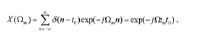
[00070] Essa transformada de Fourier pode ser considerada como o estágio de análise do codificador de voz de fase descrito acima, onde uma janela de análise plana va(n) de duração infinita é usada. De modo a se gerar um sinal de saída y(n) o qual é distendido no tempo por um fator T, isto é, um pulso de Dirac δ(t - Tto) no instante de tempo t = Tto, a fase dos sinais de sub-banda de análise deve ser multiplicada pelo fator T, de modo a se obter o sinal de sub-banda de síntese Y (Ωm) = exp(-jΩmTto), o qual produz o pulso de Dirac δ(t - Tto) como uma saída de uma transformada de Fourier inversa.[00070] This Fourier transform can be considered as the analysis stage of the phase speech encoder described above, where a flat analysis window va (n) of infinite duration is used. In order to generate an output signal y (n) which is extended in time by a factor T, that is, a Dirac pulse δ (t - Tto) at time t = Tto, the phase of the analysis subband must be multiplied by the factor T, in order to obtain the synthesis subband signal Y (Ωm) = exp (-jΩmTto), which produces the Dirac pulse δ (t - Tto) as an output of an inverse Fourier transform.
[00071] Isto mostra que a operação da multiplicação de fase dos sinais de sub-banda de análise por um fator T leva ao deslocamento de tempo desejado de um pulso de Dirac, isto é, de um sinal de entrada transiente. Deve ser notado que para sinais transientes mais realistas compreendendo mais de uma amostra não nula, as operações adicionais de distensão no tempo dos sinais de sub-banda de análise por um fator T deve ser realizada. Em outras palavras, diferentes tamanhos de salto devem ser usados na análise e no lado de síntese.[00071] This shows that the operation of the phase multiplication of the analysis subband signals by a T factor leads to the desired time shift of a Dirac pulse, that is, of a transient input signal. It should be noted that for more realistic transient signals comprising more than one non-zero sample, the additional time stretching operations of the analysis subband signals by a T factor must be performed. In other words, different heel sizes must be used in the analysis and on the synthesis side.
[00072] Contudo, deve ser notado que as considerações acima se referem a um estágio de análise / síntese usando janelas de análise e de síntese de comprimentos infinitos. De fato, um transpositor teórico com uma janela de duração infinita proporcionaria a distensão correta de um pulso de Dirac δ(t - to). Para uma análise em janela de duração finita, a situação é embaralhada pelo fato de cada bloco de análise ser para ser interpretado como um intervalo de período de um sinal periódico com um período igual ao tamanho da DFT.[00072] However, it should be noted that the above considerations refer to an analysis / synthesis stage using infinite length analysis and synthesis windows. In fact, a theoretical transposer with an infinite duration window would provide the correct distension of a Dirac δ (t - to) pulse. For a finite duration window analysis, the situation is confused by the fact that each analysis block is to be interpreted as a period interval of a periodic signal with a period equal to the size of the DFT.
[00073] Isto é ilustrado na figura 1, a qual mostra a análise e a síntese 100 de um pulso de Dirac δ(t - to). A parte superior da figura 1 mostra a entrada do estágio de análise 110 e a parte inferior da figura 1 mostra a saida do estágio de síntese 120. Os gráficos superior e inferior representam o dominio de tempo. A janela de análise estilizada 111 e a janela de síntese 121 são descritas como janelas triangulares (Barlett). O pulso de entrada δ(t - to) 112 no instante no tempo t = to é descrito no gráfico de topo 110 como uma seta vertical. É assumido que o bloco de transformada DFT é de um tamanho de M = L, isto é, o tamanho da transformada DFT é escolhido para ser igual ao tamanho das janelas. A multiplicação de fase dos sinais de sub-banda pelo fator T produzirá a análise de DFT de um pulso de Dirac δ(t - Tto) em t = Tto, embora periodizado para um trem de pulso de Dirac com período L. Isto é devido ao comprimento finito da janela aplicada e à transformada de Fourier. O trem de pulso periodizado com período L é descrito pelas setas tracejadas 123, 124 no gráfico inferior.[00073] This is illustrated in figure 1, which shows the analysis and
[00074] Em um sistema de mundo real, em que ambas as janelas de análise e de síntese são de comprimento finito, o trem de pulso realmente contém apenas uns poucos pulsos (dependendo do fator de transposição), um pulso principal, isto é, o termo desejado, uns poucos pré-pulsos, e uns poucos pós-pulsos, isto é, os termos indesejados. Os pré- e pós-pulsos emergem porque a DFT é periódica (com L). Quando um pulso está localizado em uma janela de análise, de modo que a fase complexa fique envolvida quando multiplicada por T (isto é o pulso é deslocado para fora do fim da janela e envolva de volta até o começo), um pulso indesejado emerge. Os pulsos indesejados podem ter ou não a mesma polaridade que o pulso de entrada, dependendo da localização da janela de análise e do fator de transposição.[00074] In a real world system, where both the analysis and synthesis windows are of finite length, the pulse train actually contains only a few pulses (depending on the transposition factor), a main pulse, that is, the desired term, a few pre-pulses, and a few post-pulses, that is, the unwanted terms. Pre- and post-pulses emerge because DFT is periodic (with L). When a pulse is located in an analysis window, so that the complex phase is involved when multiplied by T (that is, the pulse is moved out of the window's end and envelops back to the beginning), an unwanted pulse emerges. The unwanted pulses may or may not have the same polarity as the input pulse, depending on the location of the analysis window and the transposition factor.
[00075] Isto pode ser visto matematicamente quando da transformada do pulso de Dirac δ(t - to) situado no intervalo -L/2 < tO <L/2 usando-se uma DFT com comprimento L centralizado em torno de t = 0,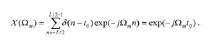
[00076] Os sinais de sub-banda de análise são de fase multiplicada por um fator T para a obtenção dos sinais de sub-banda de síntese Y (Ωm) = exp(-jΩmTto). Então, a DFT inversa é aplicada para a obtenção do sinal de síntese periódico: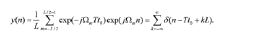
[00077] No exemplo da figura 1, a janela de síntese usa uma janela finita Vs(n) 121. A janela de síntese finita 121 captura o pulso desejado δ(t - Tto) em t = Tto, o qual é descrito como uma seta sólida 122 e cancela as outras contribuições as quais são mostradas como setas tracejadas 123, 124.[00077] In the example in figure 1, the synthesis window uses a finite window Vs (n) 121. The
[00078] Conforme o estágio de análise e de síntese se move ao longo do eixo de tempo de acordo com o fator de salto ou o passo de tempo Δt, o pulso δ(t - to) 112 terá uma outra posição em relação ao centro da respectiva janela de análise 111. Conforme destacado acima, a operação para a obtenção da distensão no tempo consiste no movimento do pulso 112 para T vezes sua posição em relação ao centro da janela. Desde que esta posição esteja na janela 121, esta operação de distensão no tempo garantirá que todas as contribuições se somem a um pulso sintetizado distendido no tempo único δ(t - Tto) em t = Tto.[00078] As the analysis and synthesis stage moves along the time axis according to the jump factor or time step Δt, the pulse δ (t - to) 112 will have another position in relation to the center of the
[00079] Contudo, ocorre um problema para a situação da figura 2, onde o pulso δ(t - to) 212 se move mais para fora em direção à borda do bloco de DFT. A figura 2 ilustra uma configuração de análise / síntese similar 200 como a figura 1. O gráfico superior 210 mostra a entrada no estágio de análise e a janela de análise 211, e o gráfico inferior 220 ilustra a saída do estágio de síntese e a janela de síntese 221. Quando da distensão no tempo do pulso de Dirac de entrada 212 por um fator T, o pulso de Dirac distendido no tempo 222, isto é, δ(t - Tto) está fora da janela de síntese 221. Ao mesmo tempo, um outro pulso de Dirac 224 do trem de pulso, isto é, δ(t - Tto + L) no instante de tempo t = Tto - L, é capturado pela janela de síntese. Em outras palavras, o pulso de Dirac de entrada 212 não é atrasado para um instante de tempo T vezes posterior, mas é movido para frente para um instante de tempo que fica antes do pulso de Dirac de entrada 212. O efeito final sobre o sinal de áudio é a ocorrência de um pré-eco a uma distância no tempo da escala das janelas de transpositor bastante longas, isto é, em um instante de tempo t = Tto - L, o qual é L - (T - 1) to anterior ao pulso de Dirac de entrada 212.[00079] However, there is a problem with the situation in figure 2, where the δ (t - to) 212 pulse moves further out towards the edge of the DFT block. Figure 2 illustrates a similar analysis /
[00080] O princípio da solução proposta pela presente invenção é descrito com referência à figura 3. A figura 3 ilustra um cenário de análise / síntese 300 similar à figura 2. O gráfico superior 310 mostra a entrada no estágio de análise com a janela de análise 311, e o gráfico inferior 320 mostra a saída do estágio de síntese com a janela de síntese 321. A ideia básica da invenção é adaptar o tamanho de DFT de modo a se evitarem pré-ecos. Isto pode ser obtido pela regulagem do tamanho M da DFT, de modo que nenhuma imagem de pulso de Dirac indesejada a partir do trem de pulso resultante seja capturada pela janela de síntese. O tamanho da transformada DFT 301 é aumentado para M = FL, onde Léo comprimento da função de janela 302 e o fator F é um fator de sobreamostragem de domínio de frequência. Em outras palavras, o tamanho da transformada DFT 301 é selecionado para ser maior do que o tamanho de janela 302. Em particular, o tamanho da transformada DFT 301 pode ser selecionado para ser maior do que o tamanho de janela 302 da janela de síntese. Devido ao comprimento aumentado 301 da transformada DFT, o período do trem de pulso compreendendo os pulsos de Dirac 322, 324 é FL. Pela seleção de um valor suficientemente grande de F, isto é, pela seleção de um fator de sobreamostragem de domínio de frequência suficientemente grande, contribuições indesejadas para a distensão de pulso podem ser canceladas. Isto é mostrado na figura 3, onde o pulso de Dirac 324 no instante t = Tto - FL fica fora da janela de síntese 321. Portanto, o pulso de Dirac 324 não é capturado pela janela de síntese 321 e, como uma consequência, pré-ecos podem ser evitados.[00080] The principle of the solution proposed by the present invention is described with reference to figure 3. Figure 3 illustrates an analysis /
[00081] Deve set notado que em uma modalidade preferida a janela de síntese e a janela de análise têm comprimentos "nominais" iguais. Contudo, quando se usa uma reamostragem implícita do sinal de saída pelo descarte ou pela inserção de amostras nas bandas de frequência da transformada ou do banco de filtro, o tamanho de janela de síntese tipicamente será diferente do tamanho de análise, dependendo da reamostragem ou do fator de transposição.[00081] It should be noted that in a preferred mode the synthesis window and the analysis window have equal "nominal" lengths. However, when using an implicit resampling of the output signal by discarding or inserting samples in the frequency bands of the transform or filter bank, the size of the synthesis window will typically differ from the analysis size, depending on the resampling or the transposition factor.
[00082] O valor mínimo de F, isto é, o fator de sobreamostragem de domínio de frequência mínimo pode ser deduzido a partir da figura 3. A condição para a não captura de imagens de pulso de Dirac indesejadas pode ser formulada conforme se segue: para qualquer pulso de entrada δ(t - to) na posição t = to < L/2, isto é, para qualquer pulso de entrada compreendido na janela de análise 311, a imagem indesejada δ(t - Tto + FL) no instante t = Tto - FL deve estar localizada na borda esquerda da janela de síntese em t = -L/2. De forma equivalente, a condição T L/2 - FL < -L/2 deve ser atendida, o que leva à regra:
[00083] Conforme pode ser visto a partir da fórmula (3), o fator de sobreamostragem de domínio de frequência mínimo F é uma função do fator de transposição / de distensão no tempo T. Mais especificamente, o fator de sobreamostragem de domínio de frequência mínimo F é proporcional ao fator de transposição / de distensão no tempo T.[00083] As can be seen from formula (3), the minimum frequency domain oversampling factor F is a function of the time span transposition / strain factor T. More specifically, the frequency domain oversampling factor minimum F is proportional to the transposition / strain factor in time T.
[00084] Pela repetição da linha de pensamento acima para o caso em que as janelas de análise e de síntese têm comprimentos diferentes, obtém-se uma forma mais geral. Sejam LA e Ls os comprimentos das janelas de análise e de síntese, respectivamente, e seja M o tamanho de DFT empregado. A fórmula de extensão da regra (3) então é:
[00085] Que esta regra de fato é uma extensão de (3) pode ser verificado pela inserção de M = FL e LA = Ls = L em (4) e dividindo-se por L em ambos os lados da equação resultante.[00085] That this rule is in fact an extension of (3) can be verified by inserting M = FL and LA = Ls = L in (4) and dividing by L on both sides of the resulting equation.
[00086] A análise acima é realizada para um modelo bem especial de um transiente, isto é, um pulso de Dirac. Contudo, o raciocínio pode ser estendido para mostrar quando se usa o esquema de distensão de tempo descrito acima, os sinais de entrada os quais têm uma envoltória espectral quase plana e os quais se anulam fora do intervalo de tempo [a, b] serão distendidos para a extração de sinais os quais são pequenos fora do intervalo [Ta, Tb]. Também pode ser checado pelo estudo de espectrogramas de sinais de áudio e/ou de fala reais que pré-ecos desaparecem nos sinais distendidos, quando a regra acima para a seleção de um fator de sobreamostragem de domínio de frequência apropriado for respeitada. Uma análise mais quantitativa também revela que pré-ecos são mais reduzidos quando se usam fatores de sobreamostragem de domínio de frequência os quais são ligeiramente inferiores para o valor imposto pela condição da fórmula (3). Isto é devido ao fato de que as funções de janela típicas vs(n) são pequenas perto de suas bordas, desse modo se atenuando pré-ecos indesejados, os quais são posicionados perto das bordas das funções de janela.[00086] The above analysis is performed for a very special model of a transient, that is, a Dirac pulse. However, the reasoning can be extended to show when using the time stretching scheme described above, the input signals which have an almost flat spectral envelope and which cancel each other out of the time interval [a, b] will be stretched for the extraction of signals which are small outside the range [Ta, Tb]. It can also be checked by studying spectrograms of actual audio and / or speech signals that pre-echoes disappear in the stretched signals, when the above rule for selecting an appropriate frequency domain oversampling factor is respected. A more quantitative analysis also reveals that pre-echoes are more reduced when using frequency domain oversampling factors which are slightly lower than the value imposed by the condition of the formula (3). This is due to the fact that the typical window functions vs (n) are small near their edges, thereby attenuating unwanted pre-echoes, which are positioned close to the edges of the window functions.
[00087] Em resumo, a presente invenção ensina uma nova forma de melhoramento da resposta transiente de transpositores harmônicos de domínio de frequência, ou distensores de tempo, pela introdução de uma transformada sobreamostrada, onde a quantidade de sobreamostragem é uma função do fluxo de trabalho escolhido.[00087] In summary, the present invention teaches a new way of improving the transient response of frequency domain harmonic transponders, or time stretches, by introducing an oversampled transform, where the amount of oversampling is a function of the workflow chosen.
[00088] A seguir, a aplicação de uma transposição harmônica de acordo com a invenção em decodificadores de áudio é descrita em maiores detalhes. Um caso de uso comum para um transpositor harmônico é em um sistema de codificador - decodificador de áudio / fala empregando uma assim denominada extensão de largura de banda ou reconstrução de frequência alta (HFR). Deve ser notado que, embora uma referência possa ser feita a uma codificação de áudio, os métodos e sistemas descritos são igualmente aplicáveis a uma codificação de fala e em uma codificação unificada de fala e de áudio (USAC).[00088] In the following, the application of a harmonic transposition according to the invention in audio decoders is described in more detail. A common use case for a harmonic transponder is in an audio / speech encoder - decoder system employing a so-called bandwidth extension or high frequency reconstruction (HFR). It should be noted that, although a reference can be made to an audio encoding, the methods and systems described are equally applicable to a speech encoding and in a unified speech and audio encoding (USAC).
[00089] Nesses sistemas de HFR, o transpositor pode ser usado para a geração de um componente de sinal de frequência alta a partir de um componente de sinal de frequência baixa provido pelo assim denominado decodificador de núcleo. O envoltório do componente de frequência alta pode ser conformado no tempo e na frequência com base em uma informação de lado portada no fluxo de bit.[00089] In these HFR systems, the transponder can be used to generate a high frequency signal component from a low frequency signal component provided by the so-called core decoder. The envelope of the high frequency component can be shaped in time and frequency based on side information carried in the bit stream.
[00090] A figura 4 ilustra a operação de um decodificador de áudio melhorado de HFR. O decodificador de áudio de núcleo 401 extrai um sinal de áudio de largura de banda baixa o qual é alimentado para um aumentador de amostra 404, o qual pode ser requerido, de modo a se produzir uma contribuição de saída de áudio final na taxa de amostragem plena desejada. Esse aumento de amostragem é requerido para sistemas de taxa dupla, onde o codificador - decodificador de áudio de núcleo de banda limitada está operando à metade da taxa de amostragem de áudio externa, enquanto a parte de HFR é processada à frequência de amostragem plena. Consequentemente, para um sistema de taxa única, este aumentador de amostra 404 é omitido. A saída de largura de banda baixa de 401 também é enviada para o transpositor ou a unidade de transposição 402, a qual extrai um sinal transposto, isto é, um sinal que compreende a faixa de frequência alta desejada. Este sinal transposto pode ser conformado no tempo e na frequência pelo ajustador de envoltória 403. A saída de áudio final é a soma de um sinal de núcleo de largura de banda e do sinal transposto de envoltória ajustada.[00090] Figure 4 illustrates the operation of an improved HFR audio decoder. The
[00091] Conforme destacado no contexto da figura 4, o sinal de saída de decodificador de núcleo pode ter a amostra aumentada como uma etapa de pré-processamento por um fator 2 na unidade de transposição 402. Uma transposição por um fator T resulta em um sinal que tem T vezes o comprimento do sinal não transposto, em um caso de distensão no tempo. De modo a se obter o deslocamento de passo desejado ou a transposição de frequência para frequências T vezes mais altas, uma redução de amostragem ou conversão de taxa do sinal distendido no tempo é subsequentemente realizada. Conforme mencionado acima, esta operação pode ser obtida através do uso de diferentes passos de análise e de síntese no codificador de voz de fase.[00091] As highlighted in the context of figure 4, the core decoder output signal may have the sample enlarged as a pre-processing step by a
[00092] A ordem de transposição geral pode ser obtida de formas diferentes. Uma primeira possibilidade é aumentar a amostra do sinal de saída de decodificador pelo ator 2 na entrada para o transpositor, conforme destacado acima. Nesses casos, o sinal distendido no tempo precisaria ter a amostra reduzida por um fator T, de modo a se obter o sinal de saída desejado, o qual é transposto na frequência por um fator T. Uma segunda possibilidade seria omitir a etapa de pré-proces- samento e realizar diretamente as operações de distensão no tempo no sinal de saída de decodificador de núcleo. Nesses casos, os sinais transpostos devem ter a amostra reduzida por um fator T/2, para a retenção do fator de aumento de amostragem global de 2, e de modo a se obter uma transposição de frequência por um fator T. Em outras palavras, o aumento de amostra do sinal de decodificador de núcleo pode ser omitido, quando da realização de uma redução de amostragem do sinal de saida do transpositor 402 de T/2, em vez de T. Deve ser notado, contudo, que o sinal de núcleo ainda precisa ter a amostragem aumentada no aumentador de amostra 404, antes da combinação do sinal com o sinal transposto.[00092] The general transposition order can be obtained in different ways. A first possibility is to increase the sample of the decoder output signal by
[00093] Também deve ser notado que o transpositor 402 pode usar vários fatores de transposição inteiros diferentes, de modo a gerar o componente de frequência alta. Isto é mostrado na figura 5, a qual ilustra a operação de um transpositor harmônico 501, o qual corresponde ao transpositor 402 da figura 4, compreendendo vários transpositores de diferente ordem de transposição ou fator de transposição T. O sinal a ser transposto é passado para o banco de transpositores individuais 501-2, 501-3, ..., 501-Tmax tendo ordens de transposição T = 2, 3, ..., Tmax, respectivamente. De forma típica, uma ordem de transposição Tmax = 4 é suficiente para a maioria das aplicações de codificação de áudio. As contribuições dos diferentes transpositores 501-2, 501-3, ..., 501- Tmax são somadas em 502, para a produção da saída de transpositor combinada. Em uma primeira modalidade, esta operação de soma pode compreender a adição das contribuições individuais. Em uma outra modalidade, as contribuições recebem pesos diferentes, de modo que o efeito de adição de múltiplas contribuições a certas frequências seja mitigado. Por exemplo, a contribuição de terceira ordem pode ser adicionada com um ganho menor do que a contribuição de segunda ordem. Finalmente, a unidade de soma 502 pode adicionar as contribuições seletivamente, dependendo da frequência de saída. Por exemplo, a transposição de segunda ordem pode ser usada para uma primeira faixa de frequência alvo mais baixa, e a transposição de terceira ordem pode ser usada para uma segunda faixa de frequência alvo mais alta.[00093] It should also be noted that
[00094] A figura 6 ilustra a operação de um transpositor harmônico, tal como um dos blocos individuais de 501, isto é, um dos transpositores 501-T da ordem de transposição T. Uma unidade de passo de análise 601 seleciona quadros sucessivos do sinal de entrada, o qual é para ser transposto. Estes quadros são sobrepostos, por exemplo, multiplicados, em uma unidade de janela de análise 602 com uma janela de análise. Deve ser notado que as operações de seleção de quadros de um sinal de entrada e multiplicação das amostras do sinal de entrada por uma função de janela de análise podem ser realizadas em uma etapa única, por exemplo, pelo uso de uma função de janela a qual é deslocada ao longo do sinal de entrada pelo passo de análise. Na unidade de transformação de análise 603, os quadros em janela do sinal de entrada são transformados no domínio de frequência. A unidade de transformação de análise 603 pode realizar, por exemplo, uma DFT. O tamanho da DFT é selecionado para ser F vezes maior do que o tamanho L da janela de análise, desse modo se gerando M = F * L coeficientes complexos de domínio de frequência. Estes coeficientes complexos são alterados na unidade de processamento não linear 604, por exemplo, pela multiplicação de sua fase pelo fator de transposição T. A sequência de coeficientes complexos de domínio de frequência, isto é, os coeficientes complexos da sequência de quadros do sinal de entrada podem ser vistos como sinais de sub-banda. A combinação de unidade de passo de análise 601, unidade de janela de análise 602 e unidade de transformação de análise 603 pode ser vista como um estágio de análise combinado ou um banco de filtro de análise.[00094] Figure 6 illustrates the operation of a harmonic transponder, such as one of the individual blocks of 501, that is, one of the transpositors 501-T of the transposition order T. An
[00095] Os coeficientes alterados ou os sinais de sub-banda alterados são retransformados no domínio de tempo usando-se a unidade de transformação de síntese 605. Para cada conjunto de coeficientes complexos alterados, isto produz um quadro de amostras alteradas, isto é, um conjunto de M amostras alteradas. Usando a primeira abertura 606, amostras L podem ser extraídas a partir de cada conjunto de amostras alteradas, desse modo se produzindo um quadro do sinal de saída. Em geral, uma sequência de quadros do sinal de saída pode ser gerada para a sequência de quadros do sinal de entrada. Esta sequência de quadros é deslocada uns com respeito aos outros pelo passo de síntese na unidade de passo de síntese 607. O passo de síntese pode ser T vezes maior do que o passo de análise. O sinal de saída é gerado na unidade de superposição - adição 608, onde os quadros deslocados do sinal de saída são sobrepostos e as amostras no mesmo instante de tempo são adicionadas. Ao atravessar o sistema acima, o sinal de entrada pode ser distendido no tempo por um fator T, isto é, o sinal de saída pode ser uma versão distendida no tempo do sinal de entrada.[00095] The altered coefficients or the altered subband signals are retransformed in the time domain using the
[00096] Finalmente, o sinal de saída pode ser contraído no tempo usando-se a unidade de contração 609. A unidade de contração 609 pode realizar uma conversão de taxa de amostragem de ordem T, isto é, pode aumentar a taxa de amostragem do sinal de saída por um fator T, enquanto mantém o número de amostras não modificado. Isto produz um sinal de saída transposto que tem o mesmo comprimento no tempo que o sinal de entrada, mas compreendendo componentes de frequência os quais são deslocados para cima por um fator T com respeito ao sinal de entrada. A unidade de combinação 609 também pode realizar uma operação de redução de amostragem por um fator T, isto é, pode reter apenas toda T-ésima amostra enquanto descarta as outras amostras. Esta operação de redução de amostragem também pode ser acompanhada por uma operação de filtro de passa baixa. Se a taxa de amostragem geral permanecer não modificada, então, o sinal de saída transposto compreenderá componentes de frequência os quais serão deslocados para cima por um fator T com respeito aos componentes de frequência do sinal de entrada.[00096] Finally, the output signal can be contracted in time using the
[00097] Deve ser notado que a unidade de contração 609 pode realizar uma combinação de conversão de taxa e redução de amostragem. A título de exemplo, a taxa de amostragem pode ser aumentada por um fator de 2. Ao mesmo tempo, o sinal pode ter a amostragem reduzida por um fator T/2. Em geral, essa combinação de conversão de taxa e redução de amostragem também leva a um sinal de saída o qual é uma transposição harmônica do sinal de entrada por um fator T. Em geral, pode ser declarado que a unidade de contração 609 realiza uma combinação de conversão de taxa e/ou de redução de amostragem, de modo a se produzir uma transposição harmônica pela ordem de transposição T. Isto é particularmente útil quando na realização de uma transposição harmônica da saída de largura de banda baixa do decodificador de áudio de núcleo 401. Conforme destacado acima, essa saída de largura de banda baixa pode ter tido a amostragem reduzida por um fator de 2 no codificador e pode requerer, portanto, um aumento de amostragem na unidade de aumento de amostragem 404, antes da fusão dela com o componente de frequência alta reconstruída. Não obstante, pode ser benéfico para a redução da complexidade de computação realizar uma transposição harmônica na unidade de transposição 402 usando a saída de largura de banda baixa "sem a amostragem aumentada". Nesses casos, a unidade de contração 609 da unidade de transposição 402 pode realizar uma conversão de taxa de ordem 2 e, desse modo, implicitamente realizar a operação de aumento de amostragem requerida do componente de frequência alta. Como uma consequência, os sinais de saída transpostos de ordem T têm a amostragem reduzida na unidade de contração 609 pelo fator T/2.[00097] It should be noted that the
[00098] No caso de múltiplos transpositores paralelos de ordens de transposição diferentes, tal como mostrado na figura 5, algumas operações de transformação ou de banco de filtro podem ser compartilhadas entre diferentes transpositores 501-2, 501-3, ..., 501- Tmax. O compartilhamento de operações de banco de filtro deve ser feito preferencialmente para a análise, de modo a se obterem implementações mais efetivas de unidades de transposição 402. Deve ser notado que uma forma preferida de reamostragem das saídas de diferentes transpositores é descartar intervalos de DFT ou canais de sub-banda antes do estágio de síntese. Desta forma, os filtros de reamostragem podem ser omitidos e a complexidade pode ser reduzida quando se realiza uma DFT inversa / um banco de filtro de síntese de tamanho menor.[00098] In the case of multiple parallel transpositors of different transposition orders, as shown in figure 5, some transformation or filter bank operations can be shared between different transpositors 501-2, 501-3, ..., 501 - Tmax. The sharing of filter bank operations should preferably be done for analysis, in order to obtain more effective implementations of 402 transposition units. It should be noted that a preferred way of resampling the outputs of different transpositors is to discard DFT intervals or subband channels before the synthesis stage. In this way, resampling filters can be omitted and complexity reduced when an inverse DFT / smaller synthesis filter bank is performed.
[00099] Conforme recém-mencionado, a janela de análise pode ser comum aos sinais de diferentes fatores de transposição. Quando se usa uma janela de análise comum, um exemplo do passo de janelas 700 aplicada ao sinal de banda baixa é descrito na figura 7. A figura 7 mostra um passo de janelas de análise 701, 702, 703 e 704, as quais são deslocadas umas com respeito às outras pelo fator de salto de análise ou pelo passo de tempo de análise Δta.[00099] As recently mentioned, the analysis window can be common to the signs of different transposition factors. When using a common analysis window, an example of the windows step 700 applied to the low band signal is described in figure 7. Figure 7 shows a step of
[000100] Um exemplo do passo de janelas aplicadas ao sinal de banda baixa, por exemplo, ao sinal de saída do decodificador de núcleo, é descrito na figura 8(a). O passo com a qual a janela de análise de comprimento L é movida para cada transformada de análise é denotada Δta. Cada transformada de análise como essa e a porção em janela do sinal de entrada também são referidas como um quadro. A transformada de análise converte / transforma o quadro de amostras de entrada em um conjunto de coeficientes complexos de FFT. Após a transformada de análise, os coeficientes complexos de FFT podem ser transformados de coordenadas cartesianas para polares. A suíte de coeficientes de FFT para quadros subsequentes constitui os sinais de sub-banda de análise. Para cada um dos fatores de transposição T = 2, 3, ..., Tmax usados, os ângulos de fase dos coeficientes de FFT são multiplicados pelo respectivo fator de transposição T e transformados de volta para coordenadas cartesianas. Daí, haverá um conjunto diferente de coeficientes complexos de FFT representando um quadro em particular para todo fator de transposição T. Em outras palavras, para cada um dos fatores de transposição T = 2, 3, Tmax e para cada quadro, um conjunto em separado de coeficientes de FFT é determinado. Como uma consequência, para toda ordem de transposição T, um conjunto Y(t*Ω ) diferente de sinais de sub-banda de síntese ■ f’ e gerado.[000100] An example of the window pitch applied to the low bandwidth signal, for example, to the core decoder output signal, is described in figure 8 (a). The step with which the analysis window of length L is moved for each analysis transform is denoted Δta. Each analysis transform like this and the window portion of the input signal is also referred to as a frame. The analysis transform converts / transforms the input sample frame into a set of complex FFT coefficients. After the analysis transform, the complex FFT coefficients can be transformed from Cartesian to polar coordinates. The suite of FFT coefficients for subsequent frames constitutes the subband analysis signals. For each of the transposition factors T = 2, 3, ..., Tmax used, the phase angles of the FFT coefficients are multiplied by the respective transposition factor T and transformed back to Cartesian coordinates. Hence, there will be a different set of complex FFT coefficients representing a particular frame for every transposition factor T. In other words, for each of the transposition factors T = 2, 3, Tmax and for each frame, a separate set of FFT coefficients is determined. As a consequence, for every transposition order T, a different set Y (t * Ω) of synthesis subband signals ■ f 'is generated.
[000101] Nos estágios de síntese, os passos de síntese Δtsdas janelas de síntese são determinadas como uma função da ordem de transposição T usada no respectivo transpositor. Conforme destacado acima, a operação de distensão no tempo também envolve a distensão no tempo dos sinais de sub-banda, isto é, a distensão no tempo da suíte de quadros. Esta operação pode ser realizada pela escolha de um fator de salto de síntese ou passo de síntese Δts, o que é aumentado em relação ao passo de análise Δtapor um fator T. Consequentemente, o passo de síntese ΔtST para o transpositor de ordem T é dada por ΔtST = TΔta. As figura 8(b) e 8(c) mostram o passo de síntese ΔtST de janelas de síntese para os fatores de transposição T = 2 e T = 3, respectivamente, onde ΔtS2 = 2Δtae ΔtS3 = 3Δta.[000101] In the synthesis stages, the synthesis steps Δts of the synthesis windows are determined as a function of the transposition order T used in the respective transposer. As noted above, the time stretch operation also involves the time stretch of the subband signals, that is, the time stretch of the frame suite. This operation can be performed by choosing a synthesis hop factor or synthesis step Δts, which is increased in relation to the analysis step Δ by a T factor. Consequently, the synthesis step ΔtST for the T-order transponder is given by ΔtST = TΔta. Figures 8 (b) and 8 (c) show the synthesis step ΔtST of synthesis windows for the transposition factors T = 2 and T = 3, respectively, where ΔtS2 = 2Δta and ΔtS3 = 3Δta.
[000102] A figura 8 também indica o tempo de referência tr, o qual foi "distendido" por um fator T = 2 e T = 3 nas figuras 8(b) e 8(c), se comparadas com a figura 8(a), respectivamente. Contudo, nas saídas este tempo de referência ÍT precisa ser alinhado para os dois fatores de transposição. Para alinhamento da saída, o sinal transposto de terceira ordem, isto é, a figura 8(c) precisa ter a amostragem reduzida ou ter a taxa convertida com o fator 3/2. Esta redução de amostragem leva a uma transposição harmônica com respeito ao sinal transposto de segunda ordem. A figura 9 ilustra o efeito da reamostragem sobre o passo de síntese de janelas para T = 3. Se for assumido que o sinal analisado é o sinal de saída de um decodificador de núcleo o qual não teve a amostragem aumentada, então, o sinal da figura 8(b) terá tido efetivamente a frequência transposta por um fator de 2, e o sinal da figura 8(c) terá tido efetivamente a frequência transposta por um fator de 3.[000102] Figure 8 also indicates the reference time tr, which was "stretched" by a factor T = 2 and T = 3 in figures 8 (b) and 8 (c), if compared with figure 8 (a ), respectively. However, at the outputs this reference time ÍT needs to be aligned for the two transposition factors. In order to align the output, the transposed third-order signal, that is, figure 8 (c) must have the sampling reduced or the rate converted with the factor 3/2. This sampling reduction leads to a harmonic transposition with respect to the second order transposed signal. Figure 9 illustrates the effect of resampling on the window synthesis step for T = 3. If it is assumed that the analyzed signal is the output signal of a core decoder which has not had the sampling increased, then the signal of the figure 8 (b) will have had the frequency transposed by a factor of 2, and the signal in figure 8 (c) will have had the frequency transposed by a factor of 3.
[000103] A seguir, o aspecto de alinhamento de tempo de sequências transpostas de diferentes fatores de transposição quando se usam janelas de análise comuns é considerado. Em outras palavras, o aspecto de alinhamento de sinais de saída de transpositores de frequência empregando uma ordem de transposição diferente é considerado. Quando se usam os métodos destacados acima, funções de Dirac δ(t - to) são distendidas no tempo, isto é, movidas ao longo do eixo de tempo, pela quantidade de tempo dada pelo fator de transposição T aplicado. De modo a se converter a operação de distensão no tempo em uma operação de deslocamento de frequência, uma decimação ou redução de amostragem usando-se o mesmo fator de transposição T é realizada. Se essa decimação pelo fator de transposição ou pela ordem de transposição T for realizada na função de Dirac distendida no tempo δ(t - Tto), o pulso de Dirac de amostragem reduzida será alinhado no tempo com respeito ao tempo de referência zero 710 na metade da primeira janela de análise 701. Isto é ilustrado na figura 7.[000103] Next, the time alignment aspect of transposed sequences of different transposition factors when using common analysis windows is considered. In other words, the aspect of alignment of output signals from frequency transponders employing a different transposition order is considered. When using the methods highlighted above, Dirac δ (t - to) functions are stretched in time, that is, moved along the time axis, by the amount of time given by the applied transposition factor T. In order to convert the time extension operation into a frequency shift operation, a decimation or sampling reduction using the same transposition factor T is performed. If this decimation by the transposition factor or by the transposition order T is performed in the Dirac function extended in time δ (t - Tto), the reduced sampled Dirac pulse will be aligned in time with respect to the reference time zero 710 in the middle of the
[000104] Contudo, quando se usam diferentes ordens de transposição T, as decimações resultarão em diferentes desvios para a referência zero, a menos que a referência zero esteja alinhada com o tempo "zero" do sinal de entrada. Como uma consequência, um ajuste de desvio de tempo dos sinais transpostos decimados precisa ser realizado, antes de eles podem ser somados na unidade de soma 502. Como um exemplo, um primeiro transpositor de ordem T = 3 e um segundo transpositor de ordem T = 4 são assumidos. Mais ainda, é assumido que o sinal de saída do decodificador de núcleo não tenha a amostragem aumentada. Então, o transpositor decima o sinal distendido no tempo de terceira ordem por um fator de 3/2, e o sinal distendido no tempo de quarta ordem por um fator 2. O sinal distendido no tempo de segunda ordem, isto é, T = 2, será exatamente interpretado como tendo uma frequência de amostragem mais alta, se comparada com o sinal de entrada, isto é, um fator de 2 mais alto de frequência de amostragem, efetivamente tornando o sinal de saída deslocado no passo por um fator de 2.[000104] However, when using different T transposition orders, the decimations will result in different deviations from the zero reference, unless the zero reference is aligned with the "zero" time of the input signal. As a consequence, a time shift adjustment of the decimated transposed signals needs to be performed, before they can be added in the
[000105] Pode ser mostrado que, de modo a alinhar os sinais transpostos e de amostragem reduzida, desvios de tempo de (T-2)L/4 precisam ser aplicados aos sinais transpostos, antes de uma decimação, isto é, para as transposições de terceira e quarta ordens, desvios de L/4 e L/2 têm que ser aplicados, respectivamente. Para se verificar isto em um exemplo concreto, será assumido que a referência zero para o sinal distendido no tempo de segunda ordem corresponda ao instante de tempo ou à amostra L/2, isto é, à referência zero 710 na figura 7. Isto é assim porque nenhuma decimação é usada. Para um sinal distendido no tempo de terceira ordem, a referência transladará para L/2 (2/3) = L/3, devido à redução de amostragem por um fator de 3/2. Se o desvio de tempo de acordo com a regra mencionada acima for adicionado antes de uma decimação, a referência transladará para (L/2 + L/4) (2/3) = L/2. Isto significa que a referência do sinal transposto de amostragem reduzida está alinhada com a referência zero 710. De uma maneira similar, para a transposição de quarta ordem sem desvio, a referência zero corresponde a L/2 (1/2) = L/4, mas, quando se usa o desvio proposto, a referência translada para (L/2 + L/2) (1/2) =L/2, o que de novo está alinhado com a referência zero de segunda ordem 710, isto é, a referência zero para o sinal transposto usando-se T = 2.[000105] It can be shown that, in order to align the transposed and reduced sampling signals, time deviations of (T-2) L / 4 need to be applied to the transposed signals, before a decimation, that is, for transpositions third and fourth orders, deviations from L / 4 and L / 2 have to be applied, respectively. In order to verify this in a concrete example, it will be assumed that the zero reference for the signal extended in the second order time corresponds to the time instant or the sample L / 2, that is, to the zero reference 710 in figure 7. This is so because no decimation is used. For a signal extended in the third order time, the reference will translate to L / 2 (2/3) = L / 3, due to the reduction of sampling by a factor of 3/2. If the time deviation according to the rule mentioned above is added before a decimation, the reference will translate to (L / 2 + L / 4) (2/3) = L / 2. This means that the reference of the transposed signal of reduced sampling is aligned with the reference zero 710. In a similar way, for the transposition of fourth order without deviation, the reference zero corresponds to L / 2 (1/2) = L / 4 , but, when using the proposed deviation, the reference translates to (L / 2 + L / 2) (1/2) = L / 2, which again is aligned with the second order zero reference 710, that is , the zero reference for the transposed signal using T = 2.
[000106] Um outro aspecto a ser considerado quando se usam simultaneamente múltiplas ordens de transposição refere-se aos ganhos aplicados às sequências transpostas de diferentes fatores de transposição. Em outras palavras, o aspecto de combinação dos sinais de saida de transpositores de ordem de transposição diferente pode ser considerado. Há dois princípios quando na seleção do ganho dos sinais transpostos, os quais podem ser considerados sob diferentes abordagens teóricas. Em qualquer um, os sinais transpostos são supostos como sendo de conservação de energia, significando que a energia total no sinal de banda baixa, o qual é subsequentemente transposto para constituir um sinal de banda alta transposto por um fator T, é preservada. Neste caso, a energia por largura de banda deve ser reduzida pelo fator de transposição T, uma vez que o sinal é distendido pela mesma quantidade T na frequência. Contudo, senoides, as quais têm sua energia em uma largura de banda infinitesimalmente pequena, reterão sua energia após uma transposição. Isto é devido ao fato de que, da mesma forma como um pulso de Dirac é movido no tempo pelo transpositor quando de uma distensão no tempo, isto é, da mesma forma que a duração no tempo do pulso não é mudada pela operação de distensão no tempo, uma senoide é movida na frequência, quando na transposição, isto é, a duração na frequência (em outras palavras, a largura de banda) não é mudada pela operação de transposição de frequência. Isto é, embora a energia por largura de banda seja reduzida em T, a senoide tem toda sua energia em um ponto na frequência, de modo que a energia no sentido de ponto seja preservada.[000106] Another aspect to be considered when using multiple transposition orders simultaneously refers to the gains applied to the transposed sequences of different transposition factors. In other words, the combination aspect of the output signals from transpositors of different transposition order can be considered. There are two principles when selecting the gain of transposed signals, which can be considered under different theoretical approaches. In either case, the transposed signals are assumed to be energy conservation, meaning that the total energy in the low band signal, which is subsequently transposed to constitute a high band signal transposed by a T factor, is preserved. In this case, the energy per bandwidth must be reduced by the transposition factor T, since the signal is stretched by the same amount T in the frequency. However, sinusoidals, which have their energy in an infinitesimally small bandwidth, will retain their energy after a transposition. This is due to the fact that, just as a Dirac pulse is moved in time by the transposer when it is distended in time, that is, in the same way that the duration in time of the pulse is not changed by the stretching operation in the time, a sinusoid is moved in frequency, when in transposition, that is, the duration in frequency (in other words, the bandwidth) is not changed by the frequency transposition operation. That is, although the energy per bandwidth is reduced by T, the sinusoid has all its energy at one point in the frequency, so that the energy in the sense of the point is preserved.
[000107] A outra opção quando na seleção do ganho dos sinais transpostos é manter a energia por largura de banda após uma transposição. Neste caso, ruído branco de banda larga e transientes exibirão uma resposta de frequência plana após uma transposição, enquanto a energia das senoides aumentará por um fator T.[000107] The other option when selecting the gain of the transposed signals is to maintain the energy per bandwidth after a transposition. In this case, white broadband noise and transients will exhibit a flat frequency response after a transposition, while the sinusoidal energy will increase by a T factor.
[000108] Um aspecto adicional da invenção é a escolha de janelas de codificador de voz de fase de análise e de síntese quando se usam janelas de análise comuns. É benéfico escolher cuidadosamente as janelas de codificador de voz de fase de análise e de síntese, isto é, Va(n) e Vs(n). Não apenas a janela de síntese vs(n) deve aderir à fórmula 2 acima, de modo a se permitir uma reconstrução perfeita. Mais ainda, a janela de análise va(n) também deve ter uma rejeição adequada dos níveis de lobo lateral. Caso contrário, termos de "descontinuidade" indesejados tipicamente serão audíveis como uma interferência com os termos principais para senoides variando na frequência. Esses termos indesejados de "descontinuidade" também podem aparecer para senoides estacionárias, no caso de fatores de transposição pares, conforme mencionado acima. A presente invenção propõe o uso de janelas de seno por causa de sua boa relação de rejeição de lobo lateral. Daí, a janela de análise é proposta como sendo:
[000109] A janela de síntese vs(n) pode ser idêntica à janela de análise Va(n) ou dada pela fórmula (2) acima, se o tamanho de salto de síntese Δts não for um fator do comprimento de janela de análise L, isto é, se o comprimento de janela de análise L não for um inteiro divisível pelo tamanho de salto de síntese. A título de exemplo se L = 1024 e Δts= 384, então, 1024 / 384 = 2,667 e não é um número inteiro. Deve ser notado que também é possível selecionar um par de janelas de análise e de síntese biortogonais, conforme destacado acima. Isto pode ser benéfico para a redução de descontinuidade no sinal de saída, notadamente quando se usam ordens de transposição T pares.[000109] The synthesis window vs (n) can be identical to the analysis window Va (n) or given by the formula (2) above, if the synthesis hop size Δts is not a factor of the analysis window length L , that is, if the analysis window length L is not an integer divisible by the synthesis hop size. For example, if L = 1024 and Δts = 384, then 1024/384 = 2,667 and it is not an integer. It should be noted that it is also possible to select a pair of biortogonal analysis and synthesis windows, as highlighted above. This can be beneficial for reducing discontinuity in the output signal, especially when using even T transposition orders.
[000110] A seguir, uma referência é feita à figura 10 e à figura 11, as quais ilustram um codificador de exemplo 1000 e um decodificador de exemplo 1100, respectivamente, para uma codificação unificada de fala e áudio (USAC). A estrutura geral do codificador 1000 e do decodificador 1100 de USAC é descrita conforme se segue: em primeiro lugar, pode haver um pré-/pós-processamento comum consistindo em uma unidade funcional de MPEG Surround (MPEGS) para lidar com processamento em estéreo ou de canal múltiplo e uma unidade de Replicação de Banda Espectral melhorada (eSBR) 1001 e 1101, respectivamente, a qual lida com a representação paramétrica das frequências de áudio mais altas no sinal de entrada, e a qual pode fazer uso dos métodos de transposição harmônica destacados no presente documento. Então, há duas ramificações, uma consistindo em um percurso de ferramenta de codificação de áudio avançada (AAC) modificada e a outra consistindo em percurso baseado em codificação de predição linear (domínio de LP ou LPC), o que por sua vez caracteriza uma representação de domínio de frequência ou uma representação de domínio de tempo da LPC residual. Todos os espectros transmitidos para ambos, AAC e LPC, podem ser representados no domínio de MDCT seguidos por uma quantificação e uma codificação aritmética. A representação de domínio de tempo pode usar um esquema de codificação de excitação ACELP.[000110] Next, a reference is made to figure 10 and figure 11, which illustrate an
[000111] A unidade de Replicação de Banda Espectral melhorada (eSBR) 1001 do codificador 1000 pode compreender componentes de reconstrução de frequência alta destacados no presente documento. Em algumas modalidades, a unidade de sSBR 1001 pode compreender uma unidade de transposição destacada no contexto das figuras 4, 5 e 6. Os dados codificados relacionados a uma transposição harmônica, por exemplo, a ordem de transposição usada, a quantidade de superamostragem de domínio de frequência necessária, ou os ganhos empregados, podem ser derivados no codificador 1000 e fundidos com a outra informação codificada em um multiplexador de fluxo de bit e encaminhados como um fluxo de áudio codificado para um decodificador correspondente 1100.[000111] The Enhanced Spectral Band Replication (eSBR)
[000112] O decodificador 1100 mostrado na figura 11 também compreende uma unidade de Replicação de Banda Espectral melhorada (eSBR) 1101. Esta unidade de eSBR 1101 recebe o fluxo de bit de áudio codificado ou o sinal codificado a partir do codificador 1000 e usa os métodos destacados no presente documento para a geração de um componente de frequência alta ou banda alta do sinal, o qual é fundido com o componente de frequência baixa ou banda baixa decodificada para a produção de um sinal decodificado. Em particular, ele pode compreender a unidade de transposição destacada no contexto das figuras 4, 5 e 6. A unidade de eSBR 1101 pode usar uma informação sobre o componente de frequência alta provido pelo codificador 1000 através do fluxo de bit, de modo a se realizar a reconstrução de frequência alta. Essa informação pode ser a envoltória espectral do componente de frequência alta original para a geração dos sinais de sub-banda de síntese e, finalmente, do componente de frequência alta do sinal decodificado, bem como a ordem de transposição usada, a quantidade de superamostragem de domínio de frequência necessária ou os ganhos empregados.[000112] Decoder 1100 shown in figure 11 also comprises an enhanced Spectral Band Replication (eSBR)
[000113] Mais ainda, as figuras 10 e 11 ilustram possíveis componentes adicionais de um codificador / decodificador de USAC, tais como: • uma ferramenta de demultiplexador de carga útil de fluxo de bit, a qual separa a carga útil de fluxo de bit nas partes para cada ferramenta, e provê a cada uma das ferramentas a informação de carga útil de fluxo de bit relacionada àquela ferramenta; • uma ferramenta de decodificação sem ruído de fator de escala, a qual toma uma informação a partir do demultiplexador de carga útil de fluxo de bit, analisa gramaticalmente aquela informação, e decodifica os fatores de escala de Huffman e de DPCM; • uma ferramenta de decodificação sem ruído espectral, a qual toma uma informação a partir do demultiplexador de carga útil de fluxo de bit, analisa gramaticalmente aquela informação, decodifica os dados codificados de forma aritmética e reconstrói os espectros quantificados; • uma ferramenta de quantificador inverso, a qual toma os valores quantificados para os espectros, e converte os valores inteiros nos espectros reconstruídos não escalonados; este quantificador é preferencialmente um quantificador de compressão e expansão, cujo fator de compressão e expansão depende do modo de codificação de núcleo escolhido; • uma ferramenta de preenchimento de ruído, a qual é usada para o preenchimento de espaços espectrais nos espectros decodificados, os quais ocorrem quando os valores espectrais são quantificados para zero, por exemplo, devido a uma forte restrição na demanda de bit no codificador; • uma ferramenta de reescalonamento, a qual converte a representação de número inteiro dos fatores de escala nos valores reais, e multiplica os espectros quantificados inversamente não escalonados pelos fatores de escala relevantes; • uma ferramenta de M/S, conforme descrito na ISO / IEC 14496-3; • uma ferramenta de conformação de ruído temporal (TNS), conforme descrito na ISO / IEC 14496-3; • uma ferramenta de comutação de banco / bloco de filtro, a qual aplica o inverso do mapeamento de frequência que foi realizado no codificador; uma transformada de cosseno discreta modificada inversa (IMDCT) preferencialmente é usada para a ferramenta de banco de filtro; • uma ferramenta de comutação de banco / bloco de filtro de distorção no tempo, a qual substitui a ferramenta de comutação de banco / bloco de filtro normal quando o modo de distorção de tempo for habilitado; o banco de filtro preferencialmente é o mesmo (IMDCT) que para o banco de filtro normal, adicionalmente as amostras em janelas de domínio de tempo são mapeadas a partir do domínio de tempo distorcido para o domínio de tempo linear por uma reamostragem variando no tempo; • uma ferramenta de MPEG Surround (MPEGS), a qual produz múltiplos sinais a partir de um ou mais sinais de entrada pela aplicação de um procedimento de upmix sofisticado para o(s) sinal(is) de entrada controlado(s) por parâmetros espaciais apropriados; no contexto de USAC, o MPEGS preferencialmente é usado para a codificação de um sinal de canal múltiplo, pela transmissão de uma informação de lado paramétrico ao longo de um sinal de downmix transmitido; • uma ferramenta classificadora de sinal, a qual analisa o sinal de entrada original e gera a partir dele uma informação de controle a qual dispara a seleção dos diferentes modos de codificação; a análise do sinal de entrada tipicamente é dependente de implementação, e tentará escolher o modo de codificação de núcleo ótimo para um dado quadro de sinal de entrada; a saída do classificador de sinal opcionalmente também pode ser usada para influenciar o comportamento de outras ferramentas, por exemplo, MPEG Surround, SBR melhorada, banco de filtro distorcido no tempo e outras; • uma ferramenta de filtro de LPC, a qual produz um sinal de domínio de tempo a partir de um sinal de domínio de excitação pela filtração do sinal de excitação reconstruído através de um filtro de síntese de predição linear; e • uma ferramenta de ACELP, a qual provê uma forma de se representar eficientemente um sinal de excitação de domínio de tempo pela combinação de um preditor de longo prazo (palavra de código adaptativa) com uma sequência tipo de pulso (palavra de código de inovação).[000113] Furthermore, figures 10 and 11 illustrate possible additional components of a USAC encoder / decoder, such as: • a bitstream payload demultiplexer tool, which separates the bitstream payload in the parts for each tool, and provides each tool with bitstream payload information related to that tool; • a scale factor noise-free decoding tool, which takes information from the bitstream payload demultiplexer, parses that information, and decodes the Huffman and DPCM scale factors; • a decoding tool without spectral noise, which takes information from the bitstream payload demultiplexer, grammatically analyzes that information, decodes the encoded data in an arithmetic way and reconstructs the quantized spectra; • an inverse quantifier tool, which takes the quantified values for the spectra, and converts the whole values into the reconstructed, non-scaled spectra; this quantifier is preferably a compression and expansion quantizer, whose compression and expansion factor depends on the chosen core coding mode; • a noise filling tool, which is used to fill spectral spaces in the decoded spectra, which occur when the spectral values are quantified to zero, for example, due to a strong restriction in the bit demand in the encoder; • a rescheduling tool, which converts the integer representation of the scale factors to the actual values, and multiplies the quantized spectra inversely not scaled by the relevant scale factors; • an M / S tool, as described in ISO / IEC 14496-3; • a temporal noise shaping tool (TNS), as described in ISO / IEC 14496-3; • a bank / filter block switching tool, which applies the inverse of the frequency mapping that was performed on the encoder; an inverse modified discrete cosine transform (IMDCT) is preferably used for the filter bank tool; • a time-warping bank / filter block switching tool, which replaces the normal bank-switch / filter block switching tool when time warping mode is enabled; the filter bank is preferably the same (IMDCT) as for the normal filter bank, additionally the samples in time domain windows are mapped from the distorted time domain to the linear time domain by a resampling varying in time; • an MPEG Surround (MPEGS) tool, which produces multiple signals from one or more input signals by applying a sophisticated upmix procedure to the input signal (s) controlled by spatial parameters appropriate; in the context of USAC, MPEGS is preferably used for encoding a multiple channel signal, by transmitting parametric side information over a transmitted downmix signal; • a signal classification tool, which analyzes the original input signal and generates control information from it which triggers the selection of the different encoding modes; the analysis of the input signal is typically implementation dependent, and will attempt to choose the optimal core encoding mode for a given input signal frame; the signal classifier output can optionally also be used to influence the behavior of other tools, for example, MPEG Surround, improved SBR, time-warped filter bank and others; • an LPC filter tool, which produces a time domain signal from an excitation domain signal by filtering the reconstructed excitation signal through a linear prediction synthesis filter; and • an ACELP tool, which provides a way to efficiently represent a time domain excitation signal by combining a long-term predictor (adaptive code word) with a pulse type sequence (innovation code word) ).
[000114] A figura 12 ilustra uma modalidade das unidades de eSBR mostradas nas figuras 10 e 11. A unidade de eSBR 1200 será descrita a seguir no contexto de um decodificador, onde a entrada para a unidade de eSBR 1200 é o componente de frequência baixa, também conhecida como banda baixa, de um sinal.[000114] Figure 12 illustrates a modality of the eSBR units shown in figures 10 and 11. The
[000115] Na figura 12, o componente de frequência baixa 1213 é alimentado em um banco de filtro de QMF, de modo a se gerarem bandas de frequência de QMF. Estas bandas de frequência de QMF não são para serem confundidas com as sub-bandas de análise destacadas neste documento. As bandas de frequência de QMF são usadas para fins de manipulação e fusão das componentes de frequência baixa e alta do sinal no domínio de frequência, em vez de no domínio de tempo. O componente de frequência baixa 1214 é alimentado para a unidade de transposição 1204, a qual corresponde aos sistemas para reconstrução de frequência alta destacados no presente documento. A unidade de transposição 1204 gera um componente de frequência alta 1212, também conhecido como banda alta, do sinal, o qual é transformado no domínio de frequência por um banco de filtro de QMF 1203. Ambas o componente de frequência baixa transformada por QMF e o componente de frequência alta transformada por QMF são alimentados em uma unidade de manipulação e de fusão 1205. Esta unidade 1205 pode realizar um ajuste de envoltória do componente de frequência alta e combina o componente de frequência alta e o componente de frequência baixa ajustados. O sinal de saída combinado é retransformado no domínio de tempo por um banco de filtro de QMF inversa 1201.[000115] In figure 12, the
[000116] Tipicamente, o banco de filtro de QMF 1202 compreende 32 bandas de frequência de QMF. Nesses casos, o componente de frequência baixa 1213 tem uma largura de banda de /s/4, onde /s/2 é a frequência de amostragem do sinal 1213. O componente de frequência alta 1212 tipicamente tem uma largura de banda de /s/2 e é filtrado através do banco de filtro 1203 compreendendo 64 bandas de frequência de QMF.[000116] Typically, the
[000117] No presente documento, um método para transposição harmônica foi destacado. Este método de transposição harmônica é particularmente bem adequado para a transposição de sinais transientes. Ele compreende a combinação de superamostragem de domínio de frequência com transposição harmônica usando codificadores de voz. A operação de transposição depende da combinação de janela de análise, passo de janela de análise, tamanho de transformada, janela de síntese, passo de janela de síntese, bem como dos ajustes de fase do sinal analisado. Através do uso deste método, efeitos indesejados, tais como pré- e pós-ecos, podem ser evitados. Mais ainda, o método não faz uso de medidas de análise de sinal, tal como detecção de transiente, as quais tipicamente introduzem distorções de sinal devido a descontinuidades no processamento de sinal. Além disso, o método proposto apenas tem complexidade computacional reduzida. O método de transposição harmônica de acordo com a invenção pode ser adicionalmente melhorado por uma seleção apropriada de janelas de análise / síntese, valores de ganho e/ou alinhamento de tempo.[000117] In the present document, a method for harmonic transposition has been highlighted. This method of harmonic transposition is particularly well suited for transposing transient signals. It comprises the combination of frequency domain oversampling with harmonic transposition using voice encoders. The transposition operation depends on the combination of analysis window, analysis window step, transform size, synthesis window, synthesis window step, as well as the phase adjustments of the analyzed signal. Through the use of this method, unwanted effects, such as pre- and post-echoes, can be avoided. Furthermore, the method does not make use of signal analysis measures, such as transient detection, which typically introduce signal distortions due to discontinuities in signal processing. In addition, the proposed method only has reduced computational complexity. The harmonic transposition method according to the invention can be further improved by an appropriate selection of analysis / synthesis windows, gain values and / or time alignment.
Claims (9)
Priority Applications (3)
| Application Number | Priority Date | Filing Date | Title |
|---|---|---|---|
| BR122019023713-1A BR122019023713B1 (en) | 2009-01-28 | 2010-03-12 | system for generating an output audio signal from an input audio signal using a transposition factor t, method for transposing an input audio signal by a transposition factor t and storage medium |
| BR122019023709-3A BR122019023709B1 (en) | 2009-01-28 | 2010-03-12 | system for generating an output audio signal from an input audio signal using a transposition factor t, method for transposing an input audio signal by a transposition factor t and storage medium |
| BR122019023712-3A BR122019023712B1 (en) | 2009-01-28 | 2010-03-12 | system for generating an output audio signal from an input audio signal using a transposition factor t, method for transposing an input audio signal by a transposition factor t and storage medium |
Applications Claiming Priority (5)
| Application Number | Priority Date | Filing Date | Title |
|---|---|---|---|
| SE0900087-8 | 2009-01-28 | ||
| SE0900087 | 2009-01-28 | ||
| US24362409P | 2009-09-18 | 2009-09-18 | |
| US61/243,624 | 2009-09-18 | ||
| PCT/EP2010/053222 WO2010086461A1 (en) | 2009-01-28 | 2010-03-12 | Improved harmonic transposition |
Publications (2)
| Publication Number | Publication Date |
|---|---|
| BRPI1007528A2 BRPI1007528A2 (en) | 2019-12-24 |
| BRPI1007528B1 true BRPI1007528B1 (en) | 2020-10-13 |
Family
ID=50896666
Family Applications (4)
| Application Number | Title | Priority Date | Filing Date |
|---|---|---|---|
| BR122019023709-3A BR122019023709B1 (en) | 2009-01-28 | 2010-03-12 | system for generating an output audio signal from an input audio signal using a transposition factor t, method for transposing an input audio signal by a transposition factor t and storage medium |
| BR122019023712-3A BR122019023712B1 (en) | 2009-01-28 | 2010-03-12 | system for generating an output audio signal from an input audio signal using a transposition factor t, method for transposing an input audio signal by a transposition factor t and storage medium |
| BR122019023713-1A BR122019023713B1 (en) | 2009-01-28 | 2010-03-12 | system for generating an output audio signal from an input audio signal using a transposition factor t, method for transposing an input audio signal by a transposition factor t and storage medium |
| BRPI1007528-3A BRPI1007528B1 (en) | 2009-01-28 | 2010-03-12 | SYSTEM FOR GENERATING AN OUTPUT AUDIO SIGNAL FROM AN INPUT AUDIO SIGNAL USING A T TRANSPOSITION FACTOR, METHOD FOR TRANSPORTING AN INPUT AUDIO SIGNAL BY A T TRANSPOSITION FACTOR AND STORAGE MEDIA |
Family Applications Before (3)
| Application Number | Title | Priority Date | Filing Date |
|---|---|---|---|
| BR122019023709-3A BR122019023709B1 (en) | 2009-01-28 | 2010-03-12 | system for generating an output audio signal from an input audio signal using a transposition factor t, method for transposing an input audio signal by a transposition factor t and storage medium |
| BR122019023712-3A BR122019023712B1 (en) | 2009-01-28 | 2010-03-12 | system for generating an output audio signal from an input audio signal using a transposition factor t, method for transposing an input audio signal by a transposition factor t and storage medium |
| BR122019023713-1A BR122019023713B1 (en) | 2009-01-28 | 2010-03-12 | system for generating an output audio signal from an input audio signal using a transposition factor t, method for transposing an input audio signal by a transposition factor t and storage medium |
Country Status (7)
| Country | Link |
|---|---|
| US (1) | US11562755B2 (en) |
| EP (2) | EP4120254A1 (en) |
| BR (4) | BR122019023709B1 (en) |
| CA (2) | CA3210604A1 (en) |
| ES (3) | ES2826324T3 (en) |
| HK (2) | HK1165077A1 (en) |
| PL (2) | PL3751570T3 (en) |
Families Citing this family (5)
| Publication number | Priority date | Publication date | Assignee | Title |
|---|---|---|---|---|
| KR101309671B1 (en) * | 2009-10-21 | 2013-09-23 | 돌비 인터네셔널 에이비 | Oversampling in a combined transposer filter bank |
| EP2980795A1 (en) * | 2014-07-28 | 2016-02-03 | Fraunhofer-Gesellschaft zur Förderung der angewandten Forschung e.V. | Audio encoding and decoding using a frequency domain processor, a time domain processor and a cross processor for initialization of the time domain processor |
| EP2980792A1 (en) * | 2014-07-28 | 2016-02-03 | Fraunhofer-Gesellschaft zur Förderung der angewandten Forschung e.V. | Apparatus and method for generating an enhanced signal using independent noise-filling |
| BR112022010062A2 (en) * | 2019-11-27 | 2022-09-06 | Fraunhofer Ges Forschung | ENCODER, DECODLER, DEVICE FOR HIDING FRAME LOSS, SYSTEM AND METHODS |
| CN111294367B (en) * | 2020-05-14 | 2020-09-01 | 腾讯科技(深圳)有限公司 | Audio signal post-processing method and device, storage medium and electronic equipment |
Family Cites Families (43)
| Publication number | Priority date | Publication date | Assignee | Title |
|---|---|---|---|---|
| US4246617A (en) | 1979-07-30 | 1981-01-20 | Massachusetts Institute Of Technology | Digital system for changing the rate of recorded speech |
| RU2256293C2 (en) | 1997-06-10 | 2005-07-10 | Коудинг Технолоджиз Аб | Improving initial coding using duplicating band |
| SE512719C2 (en) | 1997-06-10 | 2000-05-02 | Lars Gustaf Liljeryd | A method and apparatus for reducing data flow based on harmonic bandwidth expansion |
| JP3442974B2 (en) | 1997-07-30 | 2003-09-02 | 本田技研工業株式会社 | Rectification unit for absorption refrigerator |
| US7272556B1 (en) | 1998-09-23 | 2007-09-18 | Lucent Technologies Inc. | Scalable and embedded codec for speech and audio signals |
| DE60026189T2 (en) | 1999-03-25 | 2006-09-28 | Yamaha Corp., Hamamatsu | Method and apparatus for waveform compression and generation |
| SE0001926D0 (en) | 2000-05-23 | 2000-05-23 | Lars Liljeryd | Improved spectral translation / folding in the subband domain |
| AUPR141200A0 (en) | 2000-11-13 | 2000-12-07 | Symons, Ian Robert | Directional microphone |
| WO2002087137A2 (en) | 2001-04-24 | 2002-10-31 | Nokia Corporation | Methods for changing the size of a jitter buffer and for time alignment, communications system, receiving end, and transcoder |
| US6963842B2 (en) | 2001-09-05 | 2005-11-08 | Creative Technology Ltd. | Efficient system and method for converting between different transform-domain signal representations |
| JP4852228B2 (en) | 2001-09-26 | 2012-01-11 | インタラクト デヴァイシーズ インコーポレイテッド | System and method for communicating media signals |
| US6912495B2 (en) | 2001-11-20 | 2005-06-28 | Digital Voice Systems, Inc. | Speech model and analysis, synthesis, and quantization methods |
| JP3870193B2 (en) | 2001-11-29 | 2007-01-17 | コーディング テクノロジーズ アクチボラゲット | Encoder, decoder, method and computer program used for high frequency reconstruction |
| KR20060132697A (en) | 2004-02-16 | 2006-12-21 | 코닌클리케 필립스 일렉트로닉스 엔.브이. | A transcoder and method of transcoding therefore |
| TWI393121B (en) | 2004-08-25 | 2013-04-11 | Dolby Lab Licensing Corp | Method and apparatus for processing a set of n audio signals, and computer program associated therewith |
| KR100590561B1 (en) | 2004-10-12 | 2006-06-19 | 삼성전자주식회사 | Method and apparatus for pitch estimation |
| CN102148035B (en) | 2004-11-02 | 2014-06-18 | 皇家飞利浦电子股份有限公司 | Encoding and decoding of audio signals using complex-valued filter banks |
| US7386445B2 (en) | 2005-01-18 | 2008-06-10 | Nokia Corporation | Compensation of transient effects in transform coding |
| AU2005201813B2 (en) | 2005-04-29 | 2011-03-24 | Phonak Ag | Sound processing with frequency transposition |
| EP1895511B1 (en) | 2005-06-23 | 2011-09-07 | Panasonic Corporation | Audio encoding apparatus, audio decoding apparatus and audio encoding information transmitting apparatus |
| CN101233506A (en) | 2005-07-29 | 2008-07-30 | 德克萨斯仪器股份有限公司 | System and method for optimizing the operation of an oversampled discrete Fourier transform filter bank |
| US7197453B2 (en) | 2005-07-29 | 2007-03-27 | Texas Instruments Incorporated | System and method for optimizing the operation of an oversampled discrete Fourier transform filter bank |
| US7565289B2 (en) | 2005-09-30 | 2009-07-21 | Apple Inc. | Echo avoidance in audio time stretching |
| US20070083377A1 (en) | 2005-10-12 | 2007-04-12 | Steven Trautmann | Time scale modification of audio using bark bands |
| US7720677B2 (en) | 2005-11-03 | 2010-05-18 | Coding Technologies Ab | Time warped modified transform coding of audio signals |
| US8326638B2 (en) * | 2005-11-04 | 2012-12-04 | Nokia Corporation | Audio compression |
| TWI339991B (en) | 2006-04-27 | 2011-04-01 | Univ Nat Chiao Tung | Method for virtual bass synthesis |
| US7818079B2 (en) | 2006-06-09 | 2010-10-19 | Nokia Corporation | Equalization based on digital signal processing in downsampled domains |
| EP1879293B1 (en) | 2006-07-10 | 2019-02-20 | Harman Becker Automotive Systems GmbH | Partitioned fast convolution in the time and frequency domain |
| US8135047B2 (en) | 2006-07-31 | 2012-03-13 | Qualcomm Incorporated | Systems and methods for including an identifier with a packet associated with a speech signal |
| ES2834024T3 (en) | 2006-10-25 | 2021-06-16 | Fraunhofer Ges Forschung | Apparatus and procedure for the generation of audio samples in the time domain |
| FR2911228A1 (en) | 2007-01-05 | 2008-07-11 | France Telecom | TRANSFORMED CODING USING WINDOW WEATHER WINDOWS. |
| CA2698039C (en) | 2007-08-27 | 2016-05-17 | Telefonaktiebolaget Lm Ericsson (Publ) | Low-complexity spectral analysis/synthesis using selectable time resolution |
| US8121299B2 (en) | 2007-08-30 | 2012-02-21 | Texas Instruments Incorporated | Method and system for music detection |
| US8706496B2 (en) | 2007-09-13 | 2014-04-22 | Universitat Pompeu Fabra | Audio signal transforming by utilizing a computational cost function |
| DE102008015702B4 (en) | 2008-01-31 | 2010-03-11 | Fraunhofer-Gesellschaft zur Förderung der angewandten Forschung e.V. | Apparatus and method for bandwidth expansion of an audio signal |
| RU2565008C2 (en) | 2008-03-10 | 2015-10-10 | Фраунхофер-Гезелльшафт цур Фёрдерунг дер ангевандтен Форшунг Е.Ф. | Apparatus and method of processing audio signal containing transient signal |
| US8060042B2 (en) | 2008-05-23 | 2011-11-15 | Lg Electronics Inc. | Method and an apparatus for processing an audio signal |
| BR122019023684B1 (en) | 2009-01-16 | 2020-05-05 | Dolby Int Ab | system for generating a high frequency component of an audio signal and method for performing high frequency reconstruction of a high frequency component |
| EP2214165A3 (en) | 2009-01-30 | 2010-09-15 | Fraunhofer-Gesellschaft zur Förderung der angewandten Forschung e.V. | Apparatus, method and computer program for manipulating an audio signal comprising a transient event |
| CO6440537A2 (en) | 2009-04-09 | 2012-05-15 | Fraunhofer Ges Forschung | APPARATUS AND METHOD TO GENERATE A SYNTHESIS AUDIO SIGNAL AND TO CODIFY AN AUDIO SIGNAL |
| US8971551B2 (en) | 2009-09-18 | 2015-03-03 | Dolby International Ab | Virtual bass synthesis using harmonic transposition |
| KR101697497B1 (en) | 2009-09-18 | 2017-01-18 | 돌비 인터네셔널 에이비 | A system and method for transposing an input signal, and a computer-readable storage medium having recorded thereon a coputer program for performing the method |
-
2010
- 2010-03-12 PL PL20188167T patent/PL3751570T3/en unknown
- 2010-03-12 EP EP22189877.8A patent/EP4120254A1/en active Pending
- 2010-03-12 EP EP21211941.6A patent/EP3985666B1/en active Active
- 2010-03-12 ES ES17175871T patent/ES2826324T3/en active Active
- 2010-03-12 ES ES20188167T patent/ES2906255T3/en active Active
- 2010-03-12 BR BR122019023709-3A patent/BR122019023709B1/en active IP Right Grant
- 2010-03-12 BR BR122019023712-3A patent/BR122019023712B1/en active IP Right Grant
- 2010-03-12 CA CA3210604A patent/CA3210604A1/en active Pending
- 2010-03-12 BR BR122019023713-1A patent/BR122019023713B1/en active IP Right Grant
- 2010-03-12 BR BRPI1007528-3A patent/BRPI1007528B1/en active IP Right Grant
- 2010-03-12 ES ES21211941T patent/ES2930054T3/en active Active
- 2010-03-12 CA CA3162808A patent/CA3162808C/en active Active
- 2010-03-12 PL PL21211941.6T patent/PL3985666T3/en unknown
-
2012
- 2012-06-06 HK HK12105491.9A patent/HK1165077A1/en unknown
-
2016
- 2016-01-26 HK HK16100835.1A patent/HK1213079A1/en unknown
-
2021
- 2021-08-23 US US17/409,592 patent/US11562755B2/en active Active
Also Published As
| Publication number | Publication date |
|---|---|
| BRPI1007528A2 (en) | 2019-12-24 |
| US20210383817A1 (en) | 2021-12-09 |
| HK1213079A1 (en) | 2016-06-24 |
| ES2906255T3 (en) | 2022-04-13 |
| EP3985666A1 (en) | 2022-04-20 |
| EP4120254A1 (en) | 2023-01-18 |
| CA3162808C (en) | 2023-10-10 |
| PL3751570T3 (en) | 2022-03-07 |
| US11562755B2 (en) | 2023-01-24 |
| EP3985666B1 (en) | 2022-08-17 |
| ES2826324T3 (en) | 2021-05-18 |
| HK1165077A1 (en) | 2012-09-28 |
| CA3210604A1 (en) | 2010-08-05 |
| BR122019023713B1 (en) | 2020-10-27 |
| BR122019023712B1 (en) | 2020-10-27 |
| ES2930054T3 (en) | 2022-12-05 |
| BR122019023709B1 (en) | 2020-10-27 |
| PL3985666T3 (en) | 2023-05-08 |
| CA3162808A1 (en) | 2010-08-05 |
Similar Documents
| Publication | Publication Date | Title |
|---|---|---|
| ES2639716T3 (en) | Enhanced Harmonic Transposition | |
| JP7271616B2 (en) | harmonic conversion | |
| US11562755B2 (en) | Harmonic transposition in an audio coding method and system | |
| AU2021204779B2 (en) | Improved Harmonic Transposition | |
| AU2023282303B2 (en) | Improved Harmonic Transposition |
Legal Events
| Date | Code | Title | Description |
|---|---|---|---|
| B06F | Objections, documents and/or translations needed after an examination request according [chapter 6.6 patent gazette] | ||
| B06U | Preliminary requirement: requests with searches performed by other patent offices: procedure suspended [chapter 6.21 patent gazette] | ||
| B15I | Others concerning applications: loss of priority |
Free format text: PERDA DA PRIORIDADE SE 0900087-8 DE 28.01.2009 REIVINDICADA NO PCT/EP2010/053222, CONFORME AS DISPOSICOES PREVISTAS NA LEI 9.279 DE 14/05/1996 (LPI) ART. 16 7O, DECRETO NO. 635 DE 21/08/1992 E CONVENCAO DA UNIAO DE PARIS (REVISTA EM ESTOCOLMO 14/07/1967), ART. 4O, ALINEA C, ITEM 1. ESTA PERDA SE DEU PELO FATO DO BRASIL NAO ACEITAR RESTAURACAO DE PRIORIDADE (RESERVA DO BRASIL DE ACORDO COM A REGRA 49TER.1 ALINEA (G) E/OU 49TER.2 ALINEA (H) DO REGULAMENTO DE EXECUCAO DO PCT), RESTAURACAO ESTA QUE FOI CONCEDIDA PELA OMPI, JA QUE O PRAZO PARA O DEPOSITO INTERNACIONAL COM REIVINDICACAO DE PRIORIDADE ULTRAPASSOU OS 12 MESES. |
|
| B07A | Application suspended after technical examination (opinion) [chapter 7.1 patent gazette] | ||
| B09A | Decision: intention to grant [chapter 9.1 patent gazette] | ||
| B16A | Patent or certificate of addition of invention granted [chapter 16.1 patent gazette] |
Free format text: PRAZO DE VALIDADE: 10 (DEZ) ANOS CONTADOS A PARTIR DE 13/10/2020, OBSERVADAS AS CONDICOES LEGAIS. |
|
| B25G | Requested change of headquarter approved |
Owner name: DOLBY INTERNATIONAL AB (IE) |