BRPI1005261B1 - asymmetric electric braking architecture for aircraft - Google Patents
asymmetric electric braking architecture for aircraft Download PDFInfo
- Publication number
- BRPI1005261B1 BRPI1005261B1 BRPI1005261-5A BRPI1005261A BRPI1005261B1 BR PI1005261 B1 BRPI1005261 B1 BR PI1005261B1 BR PI1005261 A BRPI1005261 A BR PI1005261A BR PI1005261 B1 BRPI1005261 B1 BR PI1005261B1
- Authority
- BR
- Brazil
- Prior art keywords
- braking
- architecture
- emacs
- ebas
- actuators
- Prior art date
Links
- 230000005611 electricity Effects 0.000 claims abstract 2
- 238000011144 upstream manufacturing Methods 0.000 claims description 2
- 230000005465 channeling Effects 0.000 claims 1
- 238000005516 engineering process Methods 0.000 description 6
- 101150034273 SYS1 gene Proteins 0.000 description 1
- 230000004913 activation Effects 0.000 description 1
- 230000000903 blocking effect Effects 0.000 description 1
- 238000004891 communication Methods 0.000 description 1
- 230000000694 effects Effects 0.000 description 1
- 229920002492 poly(sulfone) Polymers 0.000 description 1
- 238000003825 pressing Methods 0.000 description 1
- 230000002265 prevention Effects 0.000 description 1
- 230000001681 protective effect Effects 0.000 description 1
Images


Classifications
-
- B—PERFORMING OPERATIONS; TRANSPORTING
- B60—VEHICLES IN GENERAL
- B60T—VEHICLE BRAKE CONTROL SYSTEMS OR PARTS THEREOF; BRAKE CONTROL SYSTEMS OR PARTS THEREOF, IN GENERAL; ARRANGEMENT OF BRAKING ELEMENTS ON VEHICLES IN GENERAL; PORTABLE DEVICES FOR PREVENTING UNWANTED MOVEMENT OF VEHICLES; VEHICLE MODIFICATIONS TO FACILITATE COOLING OF BRAKES
- B60T8/00—Arrangements for adjusting wheel-braking force to meet varying vehicular or ground-surface conditions, e.g. limiting or varying distribution of braking force
- B60T8/17—Using electrical or electronic regulation means to control braking
- B60T8/1701—Braking or traction control means specially adapted for particular types of vehicles
- B60T8/1703—Braking or traction control means specially adapted for particular types of vehicles for aircrafts
-
- B—PERFORMING OPERATIONS; TRANSPORTING
- B60—VEHICLES IN GENERAL
- B60L—PROPULSION OF ELECTRICALLY-PROPELLED VEHICLES; SUPPLYING ELECTRIC POWER FOR AUXILIARY EQUIPMENT OF ELECTRICALLY-PROPELLED VEHICLES; ELECTRODYNAMIC BRAKE SYSTEMS FOR VEHICLES IN GENERAL; MAGNETIC SUSPENSION OR LEVITATION FOR VEHICLES; MONITORING OPERATING VARIABLES OF ELECTRICALLY-PROPELLED VEHICLES; ELECTRIC SAFETY DEVICES FOR ELECTRICALLY-PROPELLED VEHICLES
- B60L7/00—Electrodynamic brake systems for vehicles in general
- B60L7/003—Dynamic electric braking by short circuiting the motor
-
- B—PERFORMING OPERATIONS; TRANSPORTING
- B60—VEHICLES IN GENERAL
- B60T—VEHICLE BRAKE CONTROL SYSTEMS OR PARTS THEREOF; BRAKE CONTROL SYSTEMS OR PARTS THEREOF, IN GENERAL; ARRANGEMENT OF BRAKING ELEMENTS ON VEHICLES IN GENERAL; PORTABLE DEVICES FOR PREVENTING UNWANTED MOVEMENT OF VEHICLES; VEHICLE MODIFICATIONS TO FACILITATE COOLING OF BRAKES
- B60T8/00—Arrangements for adjusting wheel-braking force to meet varying vehicular or ground-surface conditions, e.g. limiting or varying distribution of braking force
- B60T8/32—Arrangements for adjusting wheel-braking force to meet varying vehicular or ground-surface conditions, e.g. limiting or varying distribution of braking force responsive to a speed condition, e.g. acceleration or deceleration
- B60T8/88—Arrangements for adjusting wheel-braking force to meet varying vehicular or ground-surface conditions, e.g. limiting or varying distribution of braking force responsive to a speed condition, e.g. acceleration or deceleration with failure responsive means, i.e. means for detecting and indicating faulty operation of the speed responsive control means
- B60T8/885—Arrangements for adjusting wheel-braking force to meet varying vehicular or ground-surface conditions, e.g. limiting or varying distribution of braking force responsive to a speed condition, e.g. acceleration or deceleration with failure responsive means, i.e. means for detecting and indicating faulty operation of the speed responsive control means using electrical circuitry
-
- B—PERFORMING OPERATIONS; TRANSPORTING
- B60—VEHICLES IN GENERAL
- B60T—VEHICLE BRAKE CONTROL SYSTEMS OR PARTS THEREOF; BRAKE CONTROL SYSTEMS OR PARTS THEREOF, IN GENERAL; ARRANGEMENT OF BRAKING ELEMENTS ON VEHICLES IN GENERAL; PORTABLE DEVICES FOR PREVENTING UNWANTED MOVEMENT OF VEHICLES; VEHICLE MODIFICATIONS TO FACILITATE COOLING OF BRAKES
- B60T2270/00—Further aspects of brake control systems not otherwise provided for
- B60T2270/40—Failsafe aspects of brake control systems
- B60T2270/402—Back-up
-
- B—PERFORMING OPERATIONS; TRANSPORTING
- B60—VEHICLES IN GENERAL
- B60T—VEHICLE BRAKE CONTROL SYSTEMS OR PARTS THEREOF; BRAKE CONTROL SYSTEMS OR PARTS THEREOF, IN GENERAL; ARRANGEMENT OF BRAKING ELEMENTS ON VEHICLES IN GENERAL; PORTABLE DEVICES FOR PREVENTING UNWANTED MOVEMENT OF VEHICLES; VEHICLE MODIFICATIONS TO FACILITATE COOLING OF BRAKES
- B60T2270/00—Further aspects of brake control systems not otherwise provided for
- B60T2270/40—Failsafe aspects of brake control systems
- B60T2270/413—Plausibility monitoring, cross check, redundancy
Landscapes
- Engineering & Computer Science (AREA)
- Transportation (AREA)
- Mechanical Engineering (AREA)
- Aviation & Aerospace Engineering (AREA)
- Power Engineering (AREA)
- Regulating Braking Force (AREA)
- Valves And Accessory Devices For Braking Systems (AREA)
Abstract
ARQUITETURA DE FRENAGEM ELÉTRICA ASSIMÉTRICA PARA AERONAVE. A invenção se refere a uma arquitetura de frenagem elétrica assimétrica para aeronave, compreendendo certo número de atuadores de freio eletromecânicos (EBAs) (2) para aplicar seletivamente uma força de frenagem sobre elementos de fricção a fim de diminuir a rotação de rodas freadas, dita arquitetura compreendendo: uma unidade de controle de freio (BCU) (8) para atuar no modo normal para gerar valores de ponto de ajuste de frenagem em resposta a uma ordem de frenagem; controladores de atuador eletromecânicos (EMACs) (3), cada um incluindo pelo menos um inversor para fornecer energia elétrica para os EBAs em resposta aos valores de ponto de ajuste de frenagem; pelo menos uma unidade de energia de freio de emergência e controle (EBPCU) (10) incluindo pelo menos um inversor para fornecer energia elétrica para alguns dos EBAs em resposta a uma ordem de frenagem; e dispositivos de proteção (12) para canalizar energia fornecida pelos EMACs ou os EBPCU para os atuadores enquanto impede que energia seja desviada para a arquitetura.ASYMMETRIC ELECTRIC BRAKING ARCHITECTURE FOR AIRCRAFT. The invention relates to an asymmetric electric braking architecture for aircraft, comprising a number of electromechanical brake actuators (EBAs) (2) to selectively apply a braking force on friction elements in order to decrease the rotation of braked wheels, said architecture comprising: a brake control unit (BCU) (8) to act in normal mode to generate braking setpoint values in response to a braking order; electromechanical actuator controllers (EMACs) (3), each including at least one inverter to supply electrical power to the EBAs in response to the braking setpoint values; at least one emergency and control brake power unit (EBPCU) (10) including at least one inverter to supply electricity to some of the EBAs in response to a braking order; and protection devices (12) to channel energy supplied by EMACs or EBPCUs to actuators while preventing energy from being diverted to the architecture.
Description
[0001] A invenção se refere a uma arquitetura de frenagem elétrica assimétrica.[0001] The invention relates to an asymmetric electric braking architecture.
[0002] A prevenção de falhas de modo comum em complexas arquiteturas redundantes é uma etapa de projeto essencial que é bem conhecida aos especialistas de sistema. Falhas de modo comum são eventos que afetam certo número de elementos em uma arquitetura, que são idênticos ou similares um ao outro, e que são considerados serem independentes. O uso de tecnologias dissimilares a fim de tornar as arquiteturas com sistemas redundantes assimétricos torna possível minimizar os riscos de falhas de modo comum.[0002] Common mode failure prevention in complex redundant architectures is an essential design step that is well known to system specialists. Common mode failures are events that affect a number of elements in an architecture, which are identical or similar to each other, and which are considered to be independent. The use of dissimilar technologies to make architectures with asymmetric redundant systems makes it possible to minimize the risks of failures in a common way.
[0003] Em arquiteturas de frenagem hidráulicas, é bem conhecido fazer uso maciço do princípio de dissimilaridade. O exemplo é dado de uma arquitetura de frenagem hidráulica em que: • a frenagem é provida no modo normal por meio de uma unidade de controle de freio normal (BCU) e servoválvulas (SV) para converter um valor de ponto de ajuste de frenagem, gerado pelo BCU, em energia hidráulica para os freios. A unidade de controle de reio normal recebe ordens de frenagem via os pedais, enquanto as servoválvulas são energizadas por uma rede de energia hidráulica normal; • a frenagem é provida no modo de emergência por meio de uma unidade de controle de freio de emergência (EBCU), e por servoválvulas de acionamento direto (DDV); e • a frenagem final pode ser provida por meio de um armazenamento de reserva de energia hidráulica e por um comando de frenagem que vem da alavanca de controle de estacionamento.[0003] In hydraulic braking architectures, it is well known to make massive use of the principle of dissimilarity. The example is given of a hydraulic braking architecture in which: • braking is provided in normal mode by means of a normal brake control unit (BCU) and servo valves (SV) to convert a braking setpoint value, generated by BCU, in hydraulic energy for the brakes. The normal wire control unit receives braking orders via the pedals, while the servo valves are powered by a normal hydraulic power network; • braking is provided in emergency mode by means of an emergency brake control unit (EBCU), and by direct-acting servo valves (DDV); and • the final braking can be provided by means of a reserve of hydraulic energy reserve and by a braking command that comes from the parking control lever.
[0004] Neste tipo de arquitetura, os mesmos elementos funcionais (unidades de controle, conversores de comando/energia) são mantidos para o canal de emergência como para o canal normal, com os elementos funcionais usando tecnologias diferentes. A assimetria de tecnologia estende até o atuador de frenagem, especificamente o próprio freio. Dito freio pode incluir uma cavidade dupla de modo que uma cavidade é conectada à correspondente servoválvula SV do circuito normal e a outra cavidade é conectada à correspondente servoválvula DDV do circuito de emergência. Alternativamente, o freio pode ter somente uma única cavidade que é associada com uma válvula de efeito duplo para receber energia hidráulica a partir de um ou do outro dos canais, com ditos dois canais sendo segregados.[0004] In this type of architecture, the same functional elements (control units, command / energy converters) are maintained for the emergency channel as for the normal channel, with the functional elements using different technologies. The technology asymmetry extends to the braking actuator, specifically the brake itself. Said brake may include a double cavity so that one cavity is connected to the corresponding SV servo valve of the normal circuit and the other cavity is connected to the corresponding DDV servo valve of the emergency circuit. Alternatively, the brake may have only a single cavity that is associated with a double-acting valve to receive hydraulic energy from one or the other of the channels, with said two channels being segregated.
[0005] No campo de frenagem elétrica provida por meio de atuadores eletromecânicos, a dissimilaridade geralmente não se estende até o atuador de frenagem. A dissimilaridade termina antes de atingir o dispositivo para desligar o motor do atuador (tipicamente o inversor elétrico contido no controlador de atuador eletromecânico (EMAC) que energiza os atuadores de freio eletromecânicos (EBAs)).[0005] In the field of electric braking provided by means of electromechanical actuators, the dissimilarity does not generally extend to the braking actuator. The dissimilarity ends before reaching the device to shut off the actuator motor (typically the electrical inverter contained in the electromechanical actuator controller (EMAC) that energizes the electromechanical brake actuators (EBAs)).
[0006] Se for desejado tornar uma tal arquitetura menos sensível a falhas de modo comum, é essencial tentar tornar o circuito normal redundante de uma maneira que seja assimétrico, ou seja, pela duplicação de todos de seus elementos funcionais (BCU, EMACs) pelo uso de tecnologias diferentes, esta solução apresenta a desvantagem de ser muito cara, em termos tanto de tamanho quanto de custo.[0006] If it is desired to make such an architecture less sensitive to faults in a common way, it is essential to try to make the normal circuit redundant in a way that is asymmetrical, that is, by duplicating all of its functional elements (BCU, EMACs) by Using different technologies, this solution has the disadvantage of being very expensive, in terms of both size and cost.
[0007] A presente invenção propõe uma arquitetura inovadora que torna possível reduzir o risco de falha de modo comum no sistema normal e no sistema de emergência, mas sem meramente duplicação de maneira dissimilar.[0007] The present invention proposes an innovative architecture that makes it possible to reduce the risk of failure in a common way in the normal system and in the emergency system, but without merely duplicating in a dissimilar way.
[0008] A invenção se refere a uma arquitetura de frenagem elétrica assimétrica para aeronave, compreendendo certo número de atuadores de freio eletromecânico (EBAs) para aplicar seletivamente uma força de frenagem sobre elementos de fricção a fim de reduzir a rotação das rodas frenadas, dita arquitetura compreendendo: • uma unidade de controle de freio (BCU) para atuar no modo normal para gerar valores de ponto de ajuste de frenagem em resposta a uma ordem de frenagem; • controladores de atuador eletromecânicos (EMACs), cada energizado por uma fonte de energia elétrica de CA, e cada um incluindo pelo menos um inversor para fornecer energia elétrica para os EBAs em resposta aos valores de ponto de ajuste de frenagem; • pelo menos uma unidade de energia de freio de emergência e controle (EBPCU), energizada somente por uma fonte de energia elétrica de CC, e incluindo pelo menos um inversor para fornecer energia elétrica para alguns dos EBAs em resposta a uma ordem de frenagem; e • dispositivos de proteção para canalizar energia fornecida pelos EMACs ou os EBPCU para os atuadores enquanto impede que energia seja desviada para a arquitetura.[0008] The invention relates to an asymmetric electric braking architecture for aircraft, comprising a number of electromechanical brake actuators (EBAs) to selectively apply a braking force on friction elements in order to reduce the rotation of the braked wheels, said architecture comprising: • a brake control unit (BCU) to operate in normal mode to generate braking setpoint values in response to a braking order; • electromechanical actuator controllers (EMACs), each powered by an AC power source, and each including at least one inverter to supply electrical power to the EBAs in response to the braking setpoint values; • at least one emergency and control brake power unit (EBPCU), powered only by a DC electrical power source, and including at least one inverter to supply electrical power to some of the EBAs in response to a braking order; and • protective devices to channel energy supplied by EMACs or EBPCUs to actuators while preventing energy from being diverted to the architecture.
[0009] Assim, a redundância assimétrica não é provida pela duplicação do equipamento do sistema normal, enquanto usa tecnologias dissimilares, mas pela proposição de um sistema de emergência constituído de uma maneira que é essencialmente diferente, e pela provisão de dispositivos análogos a válvulas de efeito duplo hidráulicas, a fim de assegurar que a energia fornecida pelos EMACs ou pelo EBPCU não vá, mais precisamente, para os atuadores e não seja desviada de volta para o outro sistema.[0009] Thus, asymmetric redundancy is not provided by duplicating the equipment of the normal system, while using dissimilar technologies, but by proposing an emergency system constituted in a way that is essentially different, and by the provision of devices analogous to valves of double hydraulic effects, to ensure that the energy supplied by EMACs or EBPCU does not, more precisely, go to the actuators and is not diverted back to the other system.
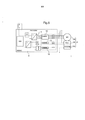
[0010] A invenção pode ser mais bem entendida na leitura da seguinte descrição de uma implementação particular da invenção: • a figura 1 é uma vista esquemática de uma arquitetura de frenagem assimétrica em uma modalidade particular da invenção, durante a operação nominal da arquitetura de frenagem; • a figura 2 é uma vista esquemática da arquitetura da figura 1, durante um modo de frenagem alternativo, em seguida à perda de um dos fornecedores de energia; • a figura 3 é uma vista esquemática da arquitetura da figura 1, durante a frenagem de emergência, em seguida à perda de um dos componentes essenciais do sistema normal; • a figura 4 é uma vista esquemática da arquitetura da figura 1, durante a frenagem final usando a unidade de emergência; e • a figura 5 é uma vista esquemática de um atuador eletromecânico e do EMAC.[0010] The invention can be better understood by reading the following description of a particular implementation of the invention: • figure 1 is a schematic view of an asymmetric braking architecture in a particular embodiment of the invention, during the nominal operation of the architecture of braking; • figure 2 is a schematic view of the architecture of figure 1, during an alternative braking mode, following the loss of one of the energy suppliers; • figure 3 is a schematic view of the architecture of figure 1, during emergency braking, following the loss of one of the essential components of the normal system; • figure 4 is a schematic view of the architecture of figure 1, during the final braking using the emergency unit; and • figure 5 is a schematic view of an electromechanical actuator and EMAC.
[0011] Com referência à figura 1, a arquitetura assimétrica da invenção, neste exemplo, é aplicada a uma aeronave que inclui um certo número de rodas frenadas 1 (somente uma dessas rodas é mostrada), ditas rodas sendo equipadas com freios que compreendem discos de freio que são pressionados um contra o outro por meio de atuadores de freio eletromecânicos 2 (EBAs). Neste exemplo, o freio inclui quatro EBAs. Os EBAs de todos dos freios são energizados pelos EMACs 3a, 3b, os quais, cada, incluem inversores 4 para fornecer energia elétrica para os EBAs sob consideração em resposta a um valor de ponto de ajuste de frenagem (brk cmd na figura). Neste exemplo, os EBAs de cada freio são energizados aos pares por dois EMACs separados. O EMAc 3a é conectado a uma primeira fonte de corrente contínua (CC) DC1 para energizar cartões eletrônicos (SW na figura) incluídos no EMAC 3a, enquanto o EMAC 3b é conectado a uma segunda fonte de energia de CC DC2 para energizar cartões eletrônicos (SW na figura) incluídos no EMAC 3b. Onde apropriado, os EMACs são também capazes de controlar os EBAs nas outras rodas.[0011] With reference to figure 1, the asymmetric architecture of the invention, in this example, is applied to an aircraft that includes a number of braked wheels 1 (only one of these wheels is shown), said wheels being equipped with brakes that comprise discs brakes that are pressed against each other by means of electromechanical brake actuators 2 (EBAs). In this example, the brake includes four EBAs. The EBAs for all of the brakes are powered by EMACs 3a, 3b, which each include
[0012] A corrente alternada (CA) que, depois da resposta intermitente pelos inversores dos EMCs 3, é fornecida para os EBAs 2, provém de duas unidades de suprimento de energia (PSU) 5, que são responsáveis pela calibração da energia que vem de duas redes de energia de CA AC1 e AC2 da aeronave.[0012] The alternating current (AC) that, after the intermittent response by the inverters of the
[0013] Os valores de ponto de ajuste de frenagem (brk cmd na figura) fornecido aos EMACs 3a, 3b são gerados por uma unidade de controle de freio BCU 8 em resposta à recepção da ordem de frenagem que vem dos pedais de freio 6 ou a partir de uma alavanca de freio de estacionamento 7. De maneira conhecida, a BCU 8 compreende dois canais de cálculo (sys1 e sys2), cada energizado por uma diferente fonte de energia de CC, respectivamente DC1 e DJC2. É conhecido tornar a BCU redundante e prover pelo menos uma segunda BCU também compreendendo dois canais de cálculo.[0013] The braking setpoint values (brk cmd in the figure) provided to EMACs 3a, 3b are generated by a
[0014] Os vários elementos descritos acima formam o sistema de frenagem normal.[0014] The various elements described above form the normal braking system.
[0015] De acordo com a invenção, o sistema de frenagem de emergência é constituído como segue: ele compreende uma unidade de energia e controle de emergência EBPCU 10 que inclui inversores 11 para gerar energia de CA para somente alguns dos atuadores 2, esta energia sendo derivada da energia de CC que provém da rede essencial (DCEss) da aeronave, ou a partir da bateria (DCBat). Neste exemplo, somente metade dos EBAs 2 da aeronave é energizada pela EBPCU (especificamente, os atuadores energizados pelo EMAC 3b). é destacado que, neste exemplo, o EBPCU 10 recebe o sinal que provém da alavanca de freio de estacionamento 7, mas não recebe nenhum sinal que vem a partir dos pedais de freio 6.[0015] According to the invention, the emergency braking system is constituted as follows: it comprises an EBPCU 10 power and emergency control unit that includes
[0016] Assim, o sistema de emergência é completamente assimétrico. Contrariamente ao princípio de dissimilaridade conhecido, no qual os elementos do sistema normal são meramente duplicados pela alteração da tecnologia usada para produzir ditos elementos, o sistema de emergência neste exemplo é essencialmente diferente do sistema normal der vários aspectos: • a EBPCU 10 recebe somente o sinal a partir da alavanca de freio de estacionamento, enquanto a BCU 8 recebe o sinal a partir dos pedais 6 e o sinal a partir da alavanca de freio de estacionamento 7; • no sistema normal, os valores de ponto de ajuste são preparados em uma unidade (a BCU) que é distinta das unidades de EMAC que contêm os inversores, enquanto isto não é verdadeiro do dispositivo de emergência; • os inversores do sistema normal são energizados com CA, enquanto o inversor do sistema de emergência é acionado com voltagem de CC, cuja fonte é presumida ser independente dos geradores que fornecem os fornecedores de energia de CA AC1 e AC2; e • o sistema normal aciona todos dos atuadores, enquanto o sistema de emergência aciona somente alguns dos atuadores.[0016] Thus, the emergency system is completely asymmetric. Contrary to the known principle of dissimilarity, in which the elements of the normal system are merely duplicated by changing the technology used to produce said elements, the emergency system in this example is essentially different from the normal system with several aspects: • EBPCU 10 receives only the signal from the parking brake lever, while BCU 8 receives the signal from the
[0017] Preferivelmente, o sistema de emergência e a EBPCU em particular não incluem nenhum software, mas somente dispositivos lógicos ligados por fios, ou mais geralmente dispositivos de hardware, para determinar um valor de ponto de ajuste de frenagem para controlar o inversor associado.[0017] Preferably, the emergency system and EBPCU in particular do not include any software, but only wired logic devices, or more generally hardware devices, to determine a brake setpoint value to control the associated drive.
[0018] Para os atuadores em consideração, o sistema de emergência inclui menos linhas de energia que no sistema normal. O elemento de bloqueio de estacionamento 2c e o resolvedor 2b (ver a figura 6) equipado em cada EBA 2 são conectados ao correspondente EMAC, mas não à EBPCU.[0018] For the actuators under consideration, the emergency system includes fewer power lines than in the normal system. The parking blocking element 2c and the
[0019] A assimetria provida desta maneira é, por conseguinte, total, mesmo não tendo o recurso para mera duplicação dissimilar de elementos do sistema normal.[0019] The asymmetry provided in this way is, therefore, total, even though it does not have the recourse for mere dissimilar duplication of elements of the normal system.
[0020] A fim de aplicar a frenagem por meio da arquitetura então descrita, os seguintes controles são disponíveis ao piloto; • os pedais de freio 6, para reduzir a velocidade da aeronave; • a alavanca de freio de estacionamento 7, para assegurar que a aeronave permaneça estacionária quanto dita aeronave parou de se mover, ou para aplicar a frenagem final como descrito abaixo; e • uma chave seletora AS/OFF 9, que permite que o piloto indique se ou não um sistema de proteção antiderrapamento deve ser aplicado.[0020] In order to apply the braking using the architecture then described, the following controls are available to the driver; • the
[0021] Os vários modos de operação da arquitetura da invenção são descritos em detalhe abaixo.[0021] The various modes of operation of the architecture of the invention are described in detail below.
[0022] Quando todos dos elementos do sistema normal estão funcionando e são normalmente energizados pelas várias fontes de energia da aeronave, o piloto pode realizar a frenagem nos seguintes modos: • modo de frenagem normal: com a chave seletora AS/OFF na posição antiderrapamento (AS), o piloto é capaz de controlar a desaceleração por meio de pedais. A BCU 8 então gera valores de ponto de ajuste de frenagem para os EMACs 3, que distribuem a energia correspondente para os EBAs 2 de modo a frear as rodas, dependendo da desaceleração desejada; e • modo de frenagem de estacionamento: quando uma vez a aeronave parou, o piloto pode assegurar que a aeronave seja mantida estacionária pela aplicação de frenagem de estacionamento por meio da alavanca de frenagem de estacionamento. A BCU 8 então gera valores de ponto de ajuste de frenagem para os EMACs 3, que distribuem a energia correspondente para os EBAs 2 de modo a pressionar ou comprimir contra os discos de freio, e então para manter a força de frenagem pelo tempo que leva para bloquear os empurradores dos EBAs 2 na posição.[0022] When all of the elements of the normal system are functioning and are normally energized by the various energy sources of the aircraft, the pilot can perform the braking in the following modes: • normal braking mode: with the AS / OFF selector switch in the anti-slip position (AS), the pilot is able to control the deceleration by means of pedals.
[0023] Em uma situação mostrada na figura 2, em que um dos geradores elétricos da aeronave apresenta falha, conduzindo à perda das correspondentes fontes de CA e CC (neste exemplo, à perda das fontes AC1 e DC1), a correspondente PSU não mais está em uma posição para prover energia para os EMACs 3a. Os cartões eletrônicos de ditos EMACs não mais são energizados. Os EBAs 2 conectados aos EMACs 3a são, portanto, inúteis. Em adição, um dos canais de cálculo da BCU é neutralizado pelo fato de que ele também não é mais energizado. Não obstante, permanece possível assegurar frenagem pelo uso do segundo canal de cálculo (sYs2) da BCU 8, a fim de gerar valores de ponto de ajuste de frenagem para os EMACs 3b que continuam a ser energizados. Dito modo de frenagem é conhecido como “modo alternativo”. Neste modo, é possível chamar os EBAs válidos 2 para exercer uma força de frenagem mais forte para compensar a perda dos EBAs não energizados 2.[0023] In a situation shown in figure 2, in which one of the aircraft's electrical generators fails, leading to the loss of the corresponding AC and DC sources (in this example, the loss of the AC1 and DC1 sources), the corresponding PSU no longer is in a position to provide power for
[0024] Em uma variante da invenção, o sistema normal pode incluir uma pluralidade de BCUs 8. A perda de uma fonte de energia de CC DC1 ou DC2, causando com que cada uma das ECUs 8 perca um de seus canais de cálculo, pode ser compensada pela reconfiguração de canais de cálculo válidos (aqueles que continuam a ser energizados) a fim de fornecer valores de ponto de ajuste para todos dos EMACs 3.[0024] In a variant of the invention, the normal system can include a plurality of
[0025] Em outra situação mostrada na figura 3, durante a qual a BCU 8 ou todos dos EMACs 3 falham (por exemplo, no caso de um enlace infinito que ocorre em software e que afeta tanto os canais de cálculo da BCU, quanto os EMACs 3a e 3b, como um resultado de uma falha de modo comum), naturalmente não é mais possível frear usando o sistema normal. O piloto observa uma tal situação quando nenhuma frenagem ocorre quando exerce pressão sobre os pedais 6. O piloto então coloca a chave seletora AS/OFF 9 na posição desligada. Este é o sinal dado para a arquitetura ativar o sistema de emergência. Este modo de frenagem é conhecido como o modo de frenagem de emergência. A frenagem é assim executada pela EBPCU 10 que recebe um sinal de frenagem a partir da alavanca de freio de estacionamento 7, que é atuada pelo piloto. A EBPCU 10 então envia energia calibrada para os EBAs 2 em consideração em resposta à atuação da alavanca de freio de estacionamento 7, a energia neste exemplo sendo extraída da fonte de energia de CC DCEss. Durante a frenagem, os empurradores do EBAs 2 naturalmente não estão bloqueados na posição, como estariam durante a frenagem de estacionamento.[0025] In another situation shown in figure 3, during which
[0026] Finalmente, em uma situação crítica, tal como aquela mostrada na figura 4, é possível que todos os geradores da aeronave apresentem falha, de uma tal maneira que fontes de energia não sejam disponíveis, além da bateria. Da mesma maneira que para a situação acima descrita, o piloto não recebe nenhuma resposta quando aplica pressão sobre os pedais. O piloto então coloca a chave seletora AS/OFF na posição desligada. O sistema de emergência é assim ativado. A frenagem é então executada pela EBPCU 10, que recebe um sinal de frenagem a partir da alavanca de freio de estacionamento que é atuada pelo piloto. A EBPCU 10 então envia energia calibrada para os EBAs 2 em consideração, em resposta à atuação da alavanca de freio de estacionamento, a energia sendo assim extraída somente das baterias DCBat. Este é o modo de frenagem final.[0026] Finally, in a critical situation, such as the one shown in figure 4, it is possible that all generators in the aircraft fail, in such a way that power sources are not available, besides the battery. As with the situation described above, the driver receives no response when applying pressure to the pedals. The pilot then sets the AS / OFF toggle switch to the off position. The emergency system is thus activated. The braking is then performed by the
[0027] Em uma implementação particular, projetada para economizar energia que vem das baterias, os EBAs 2 podem ser bloqueados em uma posição de aplicação de força, depois da primeira aplicação de força. Assim, a força de frenagem é mantida sem consumir energia que da bat4eria. Para esta finalidade, a EBPCU 10 é programada para controlar o elemento de travamento que é provido nos EBAs em consideração, depois da aplicação da força de frenagem, de modo a bloquear os empurradores de ditos EBAs 2 na posição.[0027] In a particular implementation, designed to save energy that comes from the batteries, the EBAs 2 can be locked in a position of applying force, after the first application of force. Thus, the braking force is maintained without consuming energy from the battery. For this purpose,
[0028] Em um arranjo importante mostrando na figura 5, quando o sistema de emergência é ativado e quando os EBAs 2 em consideração recebem energia a partir da EBPCU 10, é recomendável que dita energia passe para os EBAs 2 e para não poluir os EMACs em consideração por causar com que energia retorne, de maneira intempestiva, para o sistema normal. A ativação do sistema de emergência quando os EMACs 3 estão em um estado de operação apropriado não pode conduzir à energia ir da EBPCU 10 o sistema normal, uma vez que os transistores de energia que formam os inversores dos EMACs 3 são normalmente não condutores, e os inversores estão normalmente desconectados, impedindo assim que qualquer energia seja desviada. Todavia, a situação é diferente se em um dos EMACs 3 em consideração, um dos transistores permanecer na posição condutora, por exemplo, em seguida à falha de dito transistor. Neste caso, o EMAC 3 em consideração atua como um curto-circuito, e a energia fornecida pela EBPCU 10 é provável que seja desviada para o sistema normal via dito EMAc. Para superar este problema, é recomendável prover a arquitetura com dispositivos de proteção a fim de garantir que a energia fornecida pela EBPCU 10 seja, de fato, canalizada para os EBAs 2, e para prevenir que energia seja desviada para o sistema normal. Para esta finalidade. Os EMACs 3 neste exemplo são providos com fusíveis 12 em SUS linhas de saída, ditos fusíveis sendo adaptados, no caso de um transistor que permanece condutor em um dos EMACs 3, para desconectar todas as conexões entre os EBAs 2 em consideração e dito EMAC 3 quando energia está sendo fornecida pela EBPCU 10, independentemente de se ou não o EMAC 3 em consideração está sendo energizado. Neste exemplo, os fusíveis são dispostos em todas das conexões entre o EBA 2 e o EMAC 3, e nas linhas que fornecem energia para o motor 2a, para o resolvedor 2b e para o elemento de bloqueio de estacionamento 2c do EBA 2. Em uma variante, os dispositivos de proteção compreendem dispositivos ativos, como relés (normalmente abertos), em adição ou em substituição aos dispositivos passivos constituídos pelos fusíveis.[0028] In an important arrangement showing in figure 5, when the emergency system is activated and when the
[0029] De maneira similar, é também importante que a energia que vem do sistema normal, assim dos EMACs 3, seja consumida pelos EBAs 2 e que ela não seja desviada para o sistema de emergência. Para esta finalidade, a EBPCU 10 é também provida com fusíveis em ditas linhas de saída, de modo que no caso de um dos transistores do inversor da EBPCU 10 permanecer condutor, os fusos interrompem a conexão entre a EBPCU 10 e os correspondentes EBAs 2, e assim impedem que energia proveniente dos EMACs 3 seja desviada para a EBPCU 10 quando os EMACs 3 estão fornecendo energia, e por condução de dita energia para os EBAs 2 em consideração.[0029] Similarly, it is also important that the energy that comes from the normal system, as well as from
[0030] Assim, os dois sistemas são eletricamente isolados um do outro e não apresentam o risco de serem sujeitos à energia que provém do outro sistema sendo desviada para o mesmo de maneira intempestiva. É notado que os fusíveis 12 são instados nos EMACs e EBPCU a montante dos pontos comuns entre as linhas de energia que vêem dos EMACs e da EBPCU que conduzem para os mesmos atuadores.[0030] Thus, the two systems are electrically isolated from each other and do not present the risk of being subjected to the energy that comes from the other system being diverted to it in an untimely manner. It is noted that fuses 12 are installed in the EMACs and EBPCU upstream of the common points between the power lines that come from the EMACs and EBPCU that lead to the same actuators.
[0031] A arquitetura assimétrica acima descrita pode apresentar inúmeras características adicionais.[0031] The asymmetric architecture described above can have numerous additional features.
[0032] Em um aspecto particular da invenção, se o piloto usa a alavanca de freio de estacionamento, quando a chave seletora AS/OFF 9 está na posição AS, o sistema normal é então chamado e o a BCU 8 pode, por conseguinte, entender que o piloto está tentando executar a frenagem de estacionamento com os empurradores dos EBAs 2 sendo bloqueados, o que pode ser difícil se a aeronave ainda está se movendo. Por conseguinte, é recomendável verificar se o piloto realmente deseja aplicar a frenagem de estacionamento. Por conseguinte, é vantajoso monitorar informação de velocidade (velocidade da aeronave, ou velocidade da rotação de roda), a fim de verificar se aeronave está se movendo ou parou. A frenagem de estacionamento será somente aplicada se a aeronave tiver parado. A título de exemplo, a alavanca de freio de estacionamento pode ser desativada quando a chave seletora AS/OFF 9 está na posição AS.[0032] In a particular aspect of the invention, if the pilot uses the parking brake lever, when the AS /
[0033] Em outro aspecto da invenção, pode ser concebido substituir a fonte de energia DCEss pela fonte DC1 ou DC2 para fornecer energia para a EBPCU 10. É conhecido que a fonte DCEss é uma fonte de energia de CC baseada em uma combinação paralela de fontes DC1 e DC2 que obtêm sua energia a partir de respectivos geradores acionados pelos motores esquerdo e direito da aeronave. Assim, a assimetria da arquitetura é até mesmo mais pronunciada. Ao efetuar isto, um ponto comum é criado na EBPCU 10 entre a fonte DC1 (ou DC2) e a fonte DEBatt, mas nunca entre as fontes DC1 e DC2. Se uma falha de energia se propagar de DC1 para DCBatt, a fonte DC2 ainda estará disponível para o sistema normal, e a frenagem será ainda possível com este sistema.[0033] In another aspect of the invention, it may be conceived to replace the DCEss power source with the DC1 or DC2 source to supply power to the
[0034] Pode ser ainda concebido prover o sinal de pedal 6 à EBPCU 10 a fim de criar um modo de frenagem adicional (frenagem diferencial sem antiderrapamento) no caso de perda dos EMACs 3 ou das PSUs 5.[0034] It can also be conceived to provide
[0035] A comunicação entre as BCU(s) 8 e a EBPCU 10 poderia também ser colocada no local e que torna possível que os BCUs testem regularmente a EBPCU 10 para verificar que ela está operando corretamente, uma vez que a EBPCU 10 é usada somente muito excepcionalmente.[0035] Communication between BCU (s) 8 and
Claims (8)
Applications Claiming Priority (2)
| Application Number | Priority Date | Filing Date | Title |
|---|---|---|---|
| FR0959589 | 2009-12-24 | ||
| FR0959589A FR2954753B1 (en) | 2009-12-24 | 2009-12-24 | DISSYMMETRIC ELECTRIC BRAKING ARCHITECTURE FOR AIRCRAFT. |
Publications (2)
| Publication Number | Publication Date |
|---|---|
| BRPI1005261A2 BRPI1005261A2 (en) | 2013-10-01 |
| BRPI1005261B1 true BRPI1005261B1 (en) | 2021-01-26 |
Family
ID=42340728
Family Applications (1)
| Application Number | Title | Priority Date | Filing Date |
|---|---|---|---|
| BRPI1005261-5A BRPI1005261B1 (en) | 2009-12-24 | 2010-12-23 | asymmetric electric braking architecture for aircraft |
Country Status (7)
| Country | Link |
|---|---|
| US (1) | US8733847B2 (en) |
| EP (1) | EP2338748B1 (en) |
| JP (1) | JP5314001B2 (en) |
| CN (1) | CN102107610B (en) |
| BR (1) | BRPI1005261B1 (en) |
| CA (1) | CA2726671C (en) |
| FR (1) | FR2954753B1 (en) |
Families Citing this family (16)
| Publication number | Priority date | Publication date | Assignee | Title |
|---|---|---|---|---|
| US8489302B2 (en) * | 2010-09-14 | 2013-07-16 | Goodrich Corporation | Systems and methods for dynamically stable braking |
| FR2996509B1 (en) * | 2012-10-09 | 2014-12-19 | Messier Bugatti Dowty | ARCHITECTURE OF AN ELECTROMECHANICAL BRAKE SYSTEM. |
| FR2997380B1 (en) * | 2012-10-31 | 2015-12-11 | Messier Bugatti Dowty | ELECTROMECHANICAL BRAKE METHOD FOR REDUCING VIBRATIONS |
| GB2520694A (en) * | 2013-11-27 | 2015-06-03 | Airbus Operations Ltd | Aircraft electric braking system |
| GB2520696A (en) * | 2013-11-27 | 2015-06-03 | Airbus Operations Ltd | Aircraft electric braking system |
| GB2520693A (en) * | 2013-11-27 | 2015-06-03 | Airbus Operations Ltd | Aircraft electric braking system |
| CN104787311B (en) * | 2015-04-08 | 2016-09-21 | 西北工业大学 | A kind of Electrical Break System of Aircraft and Electric Brake System of Aircraft remaining control method |
| US10093298B2 (en) * | 2016-01-08 | 2018-10-09 | Goodrich Corporation | Abnormal brake behavior detection |
| FR3054201B1 (en) * | 2016-07-25 | 2018-07-27 | Safran Landing Systems | AIRCRAFT BRAKING SYSTEM WITH HIGH AVAILABILITY LEVEL |
| US10272888B2 (en) | 2016-12-09 | 2019-04-30 | Goodrich Corporation | Systems and methods for aircraft emergency and park brakes |
| FR3061139B1 (en) * | 2016-12-23 | 2019-05-31 | Safran Landing Systems | BRAKING SYSTEM ARCHITECTURE FOR AIRCRAFT |
| JP6809413B2 (en) * | 2017-08-22 | 2021-01-06 | トヨタ自動車株式会社 | Electronically controlled braking system |
| FR3086639B1 (en) * | 2018-10-01 | 2020-11-20 | Safran Landing Systems | AIRCRAFT BRAKING SYSTEM ARCHITECTURE |
| FR3096326B1 (en) | 2019-05-23 | 2022-10-28 | Safran Landing Systems | Aircraft braking system with dissimilar control devices and software module used in the event of failure |
| EP4048565A1 (en) * | 2019-10-22 | 2022-08-31 | Continental Automotive Technologies GmbH | Brake system for a motor vehicle |
| KR102200977B1 (en) * | 2019-11-27 | 2021-01-11 | 주식회사 제이앤에스 | A electronic brake system for aircraft to prevent aircraft landing accidents due to loss of brake control power |
Family Cites Families (10)
| Publication number | Priority date | Publication date | Assignee | Title |
|---|---|---|---|---|
| JP2000274464A (en) * | 1998-08-21 | 2000-10-03 | Toyota Motor Corp | Motor-driven brake device |
| US6296325B1 (en) * | 1999-07-15 | 2001-10-02 | The B. F. Goodrich Company | Method to connect and distribute power to an electromechanical braking system |
| US6402259B2 (en) * | 1999-07-14 | 2002-06-11 | Goodrich Corporation | Electromechanical braking system with power distribution and redundancy |
| US20050110339A1 (en) * | 2003-11-26 | 2005-05-26 | Kolberg David A. | EMAC arrangement for reducing wiring requirements |
| FR2862942B1 (en) * | 2003-12-01 | 2006-03-03 | Messier Bugatti | METHOD FOR MANAGING A BRAKING SYSTEM ARCHITECTURE FOR AN AIRCRAFT EQUIPPED WITH ELECTROMECHANICAL ACTUATOR BRAKES, AND ARCHITECTURE APPLYING |
| US20060108867A1 (en) * | 2004-09-17 | 2006-05-25 | Mihai Ralea | Electromechanical braking system with electrical energy back-up and regenerative energy management |
| US20080258547A1 (en) * | 2007-04-18 | 2008-10-23 | Mihai Ralea | Aircraft brake control architecture having improved power distribution and redundancy |
| ATE485981T1 (en) * | 2007-05-19 | 2010-11-15 | Goodrich Corp | AIRCRAFT BRAKE CONTROL ARCHITECTURE WITH IMPROVED ANTI-SLIP REDUNDANCY |
| US9216720B2 (en) * | 2009-04-30 | 2015-12-22 | Goodrich Corporation | Differential emergency/park electric brake system |
| US9028014B2 (en) * | 2010-12-08 | 2015-05-12 | Goodrich Corporation | System and method for providing indication of braking for electric brakes |
-
2009
- 2009-12-24 FR FR0959589A patent/FR2954753B1/en active Active
-
2010
- 2010-12-16 EP EP10195532.6A patent/EP2338748B1/en active Active
- 2010-12-22 JP JP2010286412A patent/JP5314001B2/en active Active
- 2010-12-23 BR BRPI1005261-5A patent/BRPI1005261B1/en not_active IP Right Cessation
- 2010-12-23 US US12/978,159 patent/US8733847B2/en active Active
- 2010-12-23 CA CA2726671A patent/CA2726671C/en active Active
- 2010-12-23 CN CN201010621051.8A patent/CN102107610B/en active Active
Also Published As
| Publication number | Publication date |
|---|---|
| CN102107610B (en) | 2014-11-12 |
| CA2726671C (en) | 2013-12-10 |
| JP5314001B2 (en) | 2013-10-16 |
| EP2338748A1 (en) | 2011-06-29 |
| US20110155521A1 (en) | 2011-06-30 |
| BRPI1005261A2 (en) | 2013-10-01 |
| JP2011131879A (en) | 2011-07-07 |
| CN102107610A (en) | 2011-06-29 |
| CA2726671A1 (en) | 2011-06-24 |
| FR2954753A1 (en) | 2011-07-01 |
| EP2338748B1 (en) | 2013-07-17 |
| FR2954753B1 (en) | 2012-03-09 |
| US8733847B2 (en) | 2014-05-27 |
Similar Documents
| Publication | Publication Date | Title |
|---|---|---|
| BRPI1005261B1 (en) | asymmetric electric braking architecture for aircraft | |
| BR102013026002B1 (en) | BRAKE SYSTEM ARCHITECTURE FOR AN AIRCRAFT | |
| JP6565388B2 (en) | Electric brake device | |
| BR102013005457B1 (en) | AIRCRAFT BRAKING SYSTEM | |
| BRPI0405729B1 (en) | AIRCRAFT BRAKING SYSTEM ARCHITECTURE AND MANAGEMENT PROCESS FOR AN AIRCRAFT BRAKING SYSTEM ARCHITECTURE | |
| ES2545976T3 (en) | Decentralized electric brake system | |
| CN112789203B (en) | Electric brake device for vehicle and control method thereof | |
| KR101410915B1 (en) | Electromechanical brake system with a failsafe energy supply and method for failsafe energy supply in an electromechanical brake system for vehicles | |
| JP6575175B2 (en) | Electric brake device | |
| US20220194344A1 (en) | Brake system | |
| BRPI1003898B1 (en) | aircraft emergency power network | |
| US10131329B1 (en) | Brake system power arbitration | |
| BRPI1004115A2 (en) | architecture for applying aircraft brakes to an aircraft | |
| JP2017013669A (en) | Electric brake apparatus | |
| CN110963025B (en) | Aircraft brake system architecture | |
| BRPI1001939B1 (en) | braking system architecture | |
| CN109747815A (en) | Framework for aircraft brake | |
| JP7239709B2 (en) | CONTROL ARCHITECTURE FOR ELECTRIC BRAKE AND STEERING OF VEHICLE AND CONTROL METHOD OF THE CONTROL ARCHITECTURE | |
| JP2016127702A (en) | Servo motor control apparatus | |
| BR102012008032A2 (en) | AIRCRAFT BRAKING SYSTEM ARCHITECTURE | |
| JP6620150B2 (en) | Self-diagnostic test process for railway brake systems | |
| US20150162856A1 (en) | Method and Electronic Device for Improving the Availability of an Electromechanical Actuator | |
| US20240039451A1 (en) | Motor control apparatus and motor control system | |
| US20230136605A1 (en) | Fail operational electric brake system | |
| BRPI1004015B1 (en) | power supply architecture to power aircraft brakes |
Legal Events
| Date | Code | Title | Description |
|---|---|---|---|
| B25D | Requested change of name of applicant approved |
Owner name: MESSIER-BUGATTI-DOWTY (FR) Free format text: NOME ALTERADO DE: MESSIER-BUGATTI |
|
| B25G | Requested change of headquarter approved |
Owner name: MESSIER-BUGATTI-DOWTY (FR) Free format text: ENDERECO ALTERADO CONFORME SOLICITADO NA PETICAO NO 020120020063/RJ DE 09/03/2012. |
|
| B03A | Publication of a patent application or of a certificate of addition of invention [chapter 3.1 patent gazette] | ||
| B06F | Objections, documents and/or translations needed after an examination request according [chapter 6.6 patent gazette] | ||
| B06U | Preliminary requirement: requests with searches performed by other patent offices: procedure suspended [chapter 6.21 patent gazette] | ||
| B09A | Decision: intention to grant [chapter 9.1 patent gazette] | ||
| B16A | Patent or certificate of addition of invention granted [chapter 16.1 patent gazette] |
Free format text: PRAZO DE VALIDADE: 10 (DEZ) ANOS CONTADOS A PARTIR DE 26/01/2021, OBSERVADAS AS CONDICOES LEGAIS. |
|
| B21F | Lapse acc. art. 78, item iv - on non-payment of the annual fees in time |
Free format text: REFERENTE A 13A ANUIDADE. |
|
| B24J | Lapse because of non-payment of annual fees (definitively: art 78 iv lpi, resolution 113/2013 art. 12) |
Free format text: EM VIRTUDE DA EXTINCAO PUBLICADA NA RPI 2755 DE 24-10-2023 E CONSIDERANDO AUSENCIA DE MANIFESTACAO DENTRO DOS PRAZOS LEGAIS, INFORMO QUE CABE SER MANTIDA A EXTINCAO DA PATENTE E SEUS CERTIFICADOS, CONFORME O DISPOSTO NO ARTIGO 12, DA RESOLUCAO 113/2013. |