BRPI1005020B1 - aileron geometry and fixed wing aircraft wing - Google Patents
aileron geometry and fixed wing aircraft wing Download PDFInfo
- Publication number
- BRPI1005020B1 BRPI1005020B1 BRPI1005020-5A BRPI1005020A BRPI1005020B1 BR PI1005020 B1 BRPI1005020 B1 BR PI1005020B1 BR PI1005020 A BRPI1005020 A BR PI1005020A BR PI1005020 B1 BRPI1005020 B1 BR PI1005020B1
- Authority
- BR
- Brazil
- Prior art keywords
- wing
- aileron
- geometry
- aircraft
- trailing edge
- Prior art date
Links
Images
Abstract
GEOMETRIA DE AILERON E DE ASA DE AERONAVE ASA FIXA. A presente invenção refere-se a uma geometria de aileron e a uma geometria de asa de aeronave, visando redução de força nos comandos e aumento da razão de rolamento. Mais especificamente, essa tecnologia deve ser utilizada preferencialmente em aeronaves acrobáticas, esportivas ou militares.GEOMETRY OF AILERON AND AIRCRAFT WING FIXED WING. The present invention relates to aileron geometry and aircraft wing geometry, aiming at reducing force in the controls and increasing the rolling ratio. More specifically, this technology should be used preferentially in aerobatic, sports or military aircraft.
Description
[01] A presente invenção refere-se a uma geometria de aileron e a uma geometria de asa de aeronave, visando redução de força nos comandos e aumento da razão de rolamento. Mais especificamente, essa tecnologia deve ser utilizada preferencialmente em aeronaves acrobáticas, esportivas ou militares.[01] The present invention relates to aileron geometry and aircraft wing geometry, aiming at reducing force in the controls and increasing the rolling ratio. More specifically, this technology should be used preferentially in aerobatic, sports or military aircraft.
[02] A utilização de aileron para o controle lateral de aeronaves é bastante comum e bem conhecida. A função do aileron é mover-se para cima ou para baixo (alternadamente em cada lado da asa) a fim de alterar o fluxo de ar, respectivamente diminuindo ou aumentando a sustentação naquele lado da aeronave, fazendo-a girar em torno de seu eixo longitudinal (movimento de rolagem). Ao serem acionados os ailerons, os mesmos atuam de forma inversa de cada lado da asa, ou seja, quando se quer girar o avião para a direita, o aileron da asa esquerda inclina-se para baixo e o aileron da asa direita inclina-se para cima. Com isso, a sustentação da asa direita diminui e o contrário acontece na asa esquerda, fazendo girar o avião no eixo longitudinal e para a direita.[02] The use of aileron for aircraft side control is quite common and well known. The aileron's function is to move up or down (alternately on each side of the wing) in order to change the air flow, respectively decreasing or increasing the lift on that side of the aircraft, making it rotate around its axis longitudinal (scrolling motion). When the ailerons are activated, they act in reverse on each side of the wing, that is, when you want to rotate the plane to the right, the aileron of the left wing tilts down and the aileron of the right wing tilts up. With that, the support of the right wing decreases and the opposite happens in the left wing, causing the plane to rotate in the longitudinal axis and to the right.
[03] A geometria da superfície de controle está intimamente relacionada com as forças de atuação nos comandos e com as características de desempenho das aeronaves, sobretudo com a razão de rolamento. Diversos trabalhos são encontrados na literatura a respeito da superfície de controle, sobretudo nas aeronaves acrobáticas, onde se deseja uma elevada razão de rolamento com reduzidas forças nos comandos. Então, a adoção de um dispositivo para redução de força é imprescindível. Devido à velocidade, às mudanças bruscas de altitude e aos movimentos diferenciados, as aeronaves acrobáticas necessitam de uma melhor utilização dos ailerons e assim, de uma geometria que permita que as aeronaves acrobáticas apresentem melhores desempenhos em suas funções.[03] The geometry of the control surface is closely related to the forces acting on the controls and to the performance characteristics of the aircraft, especially with the roll ratio. Several works are found in the literature regarding the control surface, especially in aerobatic aircraft, where a high rolling ratio with reduced forces on the controls is desired. Therefore, the adoption of a force reduction device is essential. Due to speed, sudden changes in altitude and different movements, aerobatic aircraft need a better use of ailerons and thus, a geometry that allows acrobatic aircraft to perform better in their functions.
[04] Atualmente, a solução mais comum é apresentada pela patente US 5033695, intitulada “Aileron Counterbalance Mount Bracket” que se refere a uma montagem de um superfície plana, rígida ao aileron, abaixo e à frente do ponto de articulação do aileron. Essa superfície, ao ser defletida, gera forças de sustentação e de arraste, que auxiliam na redução da força no comando.[04] Currently, the most common solution is presented by US patent 5033695, entitled “Aileron Counterbalance Mount Bracket” which refers to the assembly of a flat surface, rigid to the aileron, below and in front of the aileron pivot point. This surface, when deflected, generates lift and drag forces, which help to reduce the force in the control.
[05] A patente US3598340, intitulada “Airplane Aileron System”, refere- se a uma construção de um sistema de aileron para contrariar a guinada adversa de aeronaves e de hidroaviões. O aileron é formado com um membro da extensão integral chamada, para os fins dessa patente, uma spoileron. Ou seja, essa invenção usa uma extensão, já presente pedido de patente a solução para controlar a elevada razão de rolamento altera a geometria do aileron e da asa.[05] The US3598340 patent, entitled “Airplane Aileron System”, refers to the construction of an aileron system to counter the adverse yaw of aircraft and seaplanes. The aileron is formed with a member of the integral extension called, for the purposes of this patent, a spoileron. That is, this invention uses an extension, already present patent application the solution to control the high rolling ratio alters the geometry of the aileron and the wing.
[06] A patente US 6079672, intitulada “Aileron for Fixed Wing Aircraft” também se refere à disposição do aileron das aeronaves pequenas. Essa patente dispõe sobre o método de implantação dos ailerons que é composto por dois painéis localizados na parte posterior da asa, na direção “spanwise” (ao longo do eixo z) e alinhada com a borda de fuga da asa.[06] US patent 6079672, entitled “Aileron for Fixed Wing Aircraft” also refers to the aileron arrangement of small aircraft. This patent provides for the method of implanting the ailerons, which consists of two panels located at the rear of the wing, in the “spanwise” direction (along the z axis) and aligned with the trailing edge of the wing.
[07] Tendo em vista que uma asa de aeronave, durante o movimento de rolamento da mesma, está imersa em uma condição de escoamento tipicamente helicoidal. É de se esperar que os comandos de aileron tenham algum artifício para se adequarem, localmente ao longo da envergadura da asa a esta condição de escoamento. Entretanto, a solução proposta pela patente US5033695 não traz contribuição para esse fato, uma vez que menciona o uso da componente de força de arrasto (que é prejudicial para o desempenho da aeronave) para auxiliar na redução de força no comando.[07] Bearing in mind that an aircraft wing, during its rolling movement, is immersed in a typically helical flow condition. It is to be expected that the aileron controls have some artifice to adapt, locally along the wing span to this flow condition. However, the solution proposed by the patent US5033695 does not contribute to this fact, since it mentions the use of the drag force component (which is detrimental to the performance of the aircraft) to assist in the reduction of force in the command.
[08] A solução proposta não faz uso de aparatos extras aos ailerons, propriamente ditos, para reduzir a força no comando. Além disso, faz com que o aileron se adeque à condição de escoamento helicoidal sobre as asas, o que reduz o arraste e aumenta a razão de rolamento da aeronave.[08] The proposed solution does not make use of extra devices to the ailerons, properly speaking, to reduce the force in command. In addition, it makes the aileron adapt to the helical flow condition on the wings, which reduces drag and increases the aircraft's roll rate.
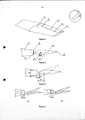
[09] A Figura 1 mostra, de forma não limitante, a vista em perspectiva de uma asa de aeronave com aileron.[09] Figure 1 shows, in a non-limiting way, the perspective view of an aircraft wing with aileron.
[010] A Figura 2 mostra, de forma não limitante, o corte da vista lateral de uma asa de aeronave com aileron.[010] Figure 2 shows, in a non-limiting way, the section of the side view of an aircraft wing with aileron.
[011] A Figura 3 mostra, de forma não limitante, o corte da vista lateral de uma asa de aeronave com aileron em duas posições distintas.[011] Figure 3 shows, in a non-limiting way, the section of the side view of an aircraft wing with aileron in two different positions.
[012] A Figura 4 mostra, de forma não limitante, o corte da vista lateral de uma asa de aeronave com aileron em duas posições distintas, a primeira mostra o corte no ponto 11(Figura 1), já a segunda mostra o corte no ponto 12 (Figura 1).[012] Figure 4 shows, in a non-limiting way, the cut of the side view of an aircraft wing with aileron in two different positions, the first shows the cut in point 11 (Figure 1), the second shows the cut in the point 12 (Figure 1).
[013] Seja admitida uma asa (1) de aeronave com aileron (2) montado em seu bordo de fuga (3). Esse aileron (2) possui bordo de ataque (4) em balanço, ou seja, seu ponto de articulação (5) é situado em um ponto sobre sua corda (6), entre o seu bordo de ataque (4) e seu bordo de fuga (7). A combinação entre a posição (8) do ponto de articulação do aileron (5) em relação ao seu bordo de ataque (4) e a espessura (9) do bordo de fuga da asa (3) deve ser feita, preferencialmente, de forma que a folga (10) entre o bordo de ataque do aileron (4) e o bordo de fuga da asa (3); quando o aileron estiver completamente defletido, seja menor na raiz da asa (11) do que na sua ponta (12) (Figuras 1, 2, 3 e 4). Para que essa geometria seja alcançada, pelo menos duas alternativas são possíveis.[013] An aircraft wing (1) with aileron (2) mounted on its trailing edge (3) is permitted. This aileron (2) has a leading edge (4) in swing, that is, its point of articulation (5) is located at a point on its rope (6), between its leading edge (4) and its leading edge. escape (7). The combination between the position (8) of the pivot point of the aileron (5) in relation to its leading edge (4) and the thickness (9) of the trailing edge of the wing (3) should preferably be done in a that the clearance (10) between the leading edge of the aileron (4) and the trailing edge of the wing (3); when the aileron is completely deflected, be smaller at the wing root (11) than at its tip (12) (Figures 1, 2, 3 and 4). For this geometry to be achieved, at least two alternatives are possible.
[014] Uma alternativa é o bordo de fuga da asa (3) compreender uma espessura (9) constante ao longo da envergadura e o ponto de articulação do aileron (5) formar uma reta que não é paralela ao bordo de fuga da asa (3), de tal forma que a posição do ponto de articulação do aileron (5) se desloque de modo a se afastar do bordo de ataque (4) e aproximar-se do bordo de fuga (7), e este deslocamento aumenta ao longo da envergadura da asa, a partir da raiz da asa, no sentido da extremidade da asa.[014] An alternative is for the trailing edge of the wing (3) to comprise a constant thickness (9) along the wingspan and the point of articulation of the aileron (5) to form a line that is not parallel to the trailing edge of the wing ( 3), in such a way that the position of the pivot point of the aileron (5) moves so as to move away from the leading edge (4) and closer to the trailing edge (7), and this displacement increases along wing span from the wing root towards the wing tip.
[015] Outra alternativa é o ponto de articulação do aileron (5) ser constante ao longo da envergadura e a espessura (9) do bordo de fuga da asa (3) variar ao longo da sua envergadura, de tal forma que a espessura (9) do bordo de fuga da asa (3) tem que ser cada vez menor quanto mais próximo da ponta asa. Sendo assim, a espessura (9) do bordo de fuga da asa (3) no ponto 11 é maior que a espessura (9) do bordo de fuga da asa (3) no ponto 12, conforme apresenta nas Figuras 1 e 4.[015] Another alternative is that the pivot point of the aileron (5) is constant along the wingspan and the thickness (9) of the trailing edge of the wing (3) varies along its wingspan, such that the thickness ( 9) the trailing edge of the wing (3) must be smaller and smaller the closer to the wing tip. Therefore, the thickness (9) of the trailing edge of the wing (3) at
[016] A escolha de uma das alternativas, bem como da regulagem dos valores adotados em cada parâmetro, dependerão das características da aeronave, da sua condição de vôo e dos valores de força no comando e razão de rolamento que se deseja obter.[016] The choice of one of the alternatives, as well as the regulation of the values adopted in each parameter, will depend on the characteristics of the aircraft, its flight condition and the values of force in the command and bearing ratio that is to be obtained.
Claims (6)
Priority Applications (1)
| Application Number | Priority Date | Filing Date | Title |
|---|---|---|---|
| BRPI1005020-5A BRPI1005020B1 (en) | 2010-12-23 | 2010-12-23 | aileron geometry and fixed wing aircraft wing |
Applications Claiming Priority (1)
| Application Number | Priority Date | Filing Date | Title |
|---|---|---|---|
| BRPI1005020-5A BRPI1005020B1 (en) | 2010-12-23 | 2010-12-23 | aileron geometry and fixed wing aircraft wing |
Publications (2)
| Publication Number | Publication Date |
|---|---|
| BRPI1005020A2 BRPI1005020A2 (en) | 2015-11-10 |
| BRPI1005020B1 true BRPI1005020B1 (en) | 2021-02-23 |
Family
ID=54548313
Family Applications (1)
| Application Number | Title | Priority Date | Filing Date |
|---|---|---|---|
| BRPI1005020-5A BRPI1005020B1 (en) | 2010-12-23 | 2010-12-23 | aileron geometry and fixed wing aircraft wing |
Country Status (1)
| Country | Link |
|---|---|
| BR (1) | BRPI1005020B1 (en) |
Families Citing this family (1)
| Publication number | Priority date | Publication date | Assignee | Title |
|---|---|---|---|---|
| CN107697270A (en) * | 2017-09-29 | 2018-02-16 | 南京航空航天大学 | Dismantled and assembled aileron mounting structure |
-
2010
- 2010-12-23 BR BRPI1005020-5A patent/BRPI1005020B1/en active IP Right Grant
Also Published As
| Publication number | Publication date |
|---|---|
| BRPI1005020A2 (en) | 2015-11-10 |
Similar Documents
| Publication | Publication Date | Title |
|---|---|---|
| CA2607358C (en) | System for controlling flight direction | |
| US8876044B2 (en) | Aircraft with yaw control by differential drag | |
| ES2373812B1 (en) | AIRCRAFT HORIZONTAL STABILIZING SURFACE. | |
| US7661630B2 (en) | High lift longitudinal axis control system | |
| BR112017004139B1 (en) | MULTI-ROTOR WITH TILTED WING | |
| US20150102156A1 (en) | Aircraft wing having continuously rotating wing tips | |
| BRPI1106276A2 (en) | variable geometry aircraft | |
| BR112017016524B1 (en) | propeller powered aircraft | |
| BRPI0712881A2 (en) | adjustable horizontal stabilizer | |
| BRPI0821412B1 (en) | ENGINE CONFIGURATION FOR AIRCRAFT LOCATED AT THE BACK OF THE DITA AIRCRAFT FUSELAGE | |
| EP2923945B1 (en) | Ornithopter | |
| KR101723666B1 (en) | A rotorcraft having an advanced pitch stabilizer | |
| JP2021187325A (en) | Flight efficiency improving system in compound helicopter | |
| WO2022078258A1 (en) | Flapping wing aircraft | |
| JP6376667B2 (en) | Aircraft stabilization system and method for modifying an aircraft thereby | |
| EP2923944B1 (en) | Ornithopter | |
| BRPI1005020B1 (en) | aileron geometry and fixed wing aircraft wing | |
| JP2021154802A (en) | Flying body | |
| US8474747B2 (en) | Pivoting stabilising surface for aircraft | |
| EP3842337B1 (en) | Helicopter, helicopter kit and associated reconfiguration method | |
| KR20210122236A (en) | Aircraft and related manufacturing methods | |
| JP2023518770A (en) | Helicopter, helicopter kit and related reconfiguration method | |
| ES1269111U (en) | FLAP PROPULSION AERONAUTICAL DEVICE WITH PROPELLER MOTOR (Machine-translation by Google Translate, not legally binding) | |
| JP2005088804A (en) | Variable delta wing airplane and its fuselage attitude controlling method |
Legal Events
| Date | Code | Title | Description |
|---|---|---|---|
| B03A | Publication of an application: publication of a patent application or of a certificate of addition of invention | ||
| B08F | Application fees: dismissal - article 86 of industrial property law | ||
| B08H | Application fees: decision cancelled |
Free format text: ANULADA A PUBLICACAO CODIGO 8.6 NA RPI NO 2406 DE 14/02/2017 POR TER SIDO INDEVIDA. |
|
| B06F | Objections, documents and/or translations needed after an examination request according art. 34 industrial property law | ||
| B06A | Notification to applicant to reply to the report for non-patentability or inadequacy of the application according art. 36 industrial patent law | ||
| B09A | Decision: intention to grant | ||
| B16A | Patent or certificate of addition of invention granted |
Free format text: PRAZO DE VALIDADE: 10 (DEZ) ANOS CONTADOS A PARTIR DE 23/02/2021, OBSERVADAS AS CONDICOES LEGAIS. |