BRPI1002049B1 - solids, water and oil separator system for wastewater treatment - Google Patents
solids, water and oil separator system for wastewater treatment Download PDFInfo
- Publication number
- BRPI1002049B1 BRPI1002049B1 BRPI1002049-7A BRPI1002049A BRPI1002049B1 BR PI1002049 B1 BRPI1002049 B1 BR PI1002049B1 BR PI1002049 A BRPI1002049 A BR PI1002049A BR PI1002049 B1 BRPI1002049 B1 BR PI1002049B1
- Authority
- BR
- Brazil
- Prior art keywords
- water
- oil
- box
- spillway
- separator system
- Prior art date
Links
Images


Landscapes
- Removal Of Floating Material (AREA)
Abstract
sistema separador de sólidos, água e óleos, de funcionamento contínuo, com câmaras e dispositivo para retenção de emulsões e de micropartículas, com controle de lâmina d'água e de vazão. a presente patente de invenção refere-se a sistema separador de sólidos água e óleos, destinado principalmente ao tratamento das águas residuárias contaminadas por sólidos, óleos e graxos, de funcionamento contínuo, composto por caixas/câmaras sequenciais de separação interligadas por tubos que também regulam as vazões, sendo: caixa de sólidos (1.1) dotada de crivo longo (4) assentado em sua saída no duto regulador de vazão (3.2), que pelas suas frestas verticais (4.1) permite a passagem do efluente líquido para a caixa de tranquilização (1.2) e retém em seu fundo todos os materiais (f) de densidades maiores; caixa de tranquilização (1.2) dotada de dispositivo desnivelador (5) formado por duas conexões em "t" (5.1) e (5.2) para retenção de emulsões e micropartículas; caixa sifonada (1.3) dotada de septo com visita (7) dotado de um tampão (8), e de calha vertedoura em curva reversa (6) para controle de lâmina d'água com calha vertedoura em curva reversa, provenientes de lavadores de máquinas e de veículos, e de indústrias, pátios de garagens, oficinas e postos de serviços em veículos.continuous separator system for solids, water and oils, with chambers and device for retaining emulsions and microparticles, with water flow and flow control. the present invention patent refers to a water and oil solids separator system, intended mainly for the treatment of wastewater contaminated by solids, oils and greases, of continuous operation, consisting of sequential separation boxes / chambers interconnected by tubes that also regulate flow rates, as follows: solid box (1.1) equipped with a long sieve (4) seated at its outlet in the flow regulating duct (3.2), which through its vertical cracks (4.1) allows the passage of liquid effluent to the still box (1.2) and retains in its bottom all materials (f) of greater densities; tranquilization box (1.2) equipped with a leveling device (5) formed by two "t" connections (5.1) and (5.2) for retaining emulsions and microparticles; siphon box (1.3) equipped with a visiting septum (7) equipped with a plug (8), and a spillway chute in reverse curve (6) to control water depth with a spillway chute in reverse curve, from machine washers and vehicles, and industries, garage yards, workshops and vehicle service stations.
Description
A presente patente de invenção refere-se a sistema separador de sólidos água e óleos, de funcionamento contínuo, composto por caixas/câmaras de separação interligadas por tubos que também regulam as vazões, sendo uma delas uma caixa de tranquilização dotada de dispositivo desnivelador com duas conexões em “T” para retenção de emulsões e micropartículas e outra delas dotada de dispositivo para controle de lâmina d’água com calha vertedoura em curva reversa, destinado principalmente ao tratamento das águas residuárias contaminadas por sólidos, óleos e graxos, provenientes de lavadores de máquinas e de veículos, e de indústrias, pátios de garagens, oficinas e postos de serviços em veículos.The present invention patent refers to a continuous separator system for water and oil solids, consisting of boxes / separation chambers interconnected by tubes that also regulate the flow rates, one of which is a tranquility box with a leveling device with two “T” connections for the retention of emulsions and microparticles and another one with a device for controlling water depth with a spillway chute in reverse curve, intended mainly for the treatment of wastewater contaminated by solids, oils and greases, coming from washing machines. machines and vehicles, and industries, garage yards, workshops and service stations in vehicles.
As águas servidas provenientes destas unidades estão poluídas por óleos, que se apresentam em várias formas: - óleo livre: é aquele misturado com a água em pequenos glóbulos que tendem a flutuar; - óleo emulsionado: esta emulsão de óleo e água é obtida através de bombeamentos e jatos d’água sob pressão que se dispersa na água, com uma tênue tendência à coalescência, à coagulação e à flutuação; são partículas menores que 30 micras (p); - óleo dissolvido: é o óleo solubilizado em um líquido solvente e pode ser detectado misturado na água; os separadores que utilizam a diferença de densidade não o removem.The wastewater from these units is polluted by oils, which come in various forms: - free oil: it is that mixed with water in small globules that tend to float; - emulsified oil: this oil and water emulsion is obtained through pumping and water jets under pressure that are dispersed in water, with a slight tendency to coalescence, coagulation and fluctuation; are particles smaller than 30 microns (p); - dissolved oil: it is the oil solubilized in a solvent liquid and can be detected mixed in water; separators that use the density difference do not remove it.
A patente MU7802872-8 refere-se a um "Sistema Separador e Coletor de Água e Óleo" que utiliza uma bóia regulável, fabricada com material de densidade tal que flutua na água e imerge no óleo. Esta bóia é ainda acoplada a uma válvula que fecha ou abre a passagem para a água, conforme a quantidade relativa de óleo que está adentrando ao sistema.The MU7802872-8 patent refers to a "Water and Oil Separator and Collector System" that uses an adjustable float, manufactured with material of such density that it floats in water and immerses itself in oil. This float is also coupled to a valve that closes or opens the passage for the water, according to the relative amount of oil that is entering the system.
A patente BR 7902311(U) refere-se a um "Equipamento Separador Água-Óleo", confeccionado em PEAD através do processo de rotomoldagem, apresentando formato basicamente paralelepipédico com vértices arredondados e arestas que sofrem ligeiro alargamento em seucentro vertical.The patent BR 7902311 (U) refers to a "Water-Oil Separator Equipment", made of HDPE through the rotational molding process, presenting a basically parallelepiped shape with rounded vertices and edges that undergo a slight widening in its vertical center.
Diferentemente de tais anterioridades, que se referem a separadores de água e óleo, a presente patente é um sistema separador de sólidos, água e óleos (S.A.O.), ideal para postos de serviços (lavagens) em veículos, onde a incidência de sólidos é grande e a de óleos é ínfima, podendo também ser utilizada em estabelecimentos industriais e comerciais com descarte de óleos.Unlike these previous ones, which refer to water and oil separators, the present patent is a system for separating solids, water and oils (SAO), ideal for service stations (washing) in vehicles, where the incidence of solids is large and that of oils is negligible, and can also be used in industrial and commercial establishments with oil disposal.
Esta nova patente composta por caixas sequenciais interligadas funciona sem recomendação de intermitência, apresentando como maior novidade a inclusão da caixa de tranquilização com o dispositivo para a retenção específica das micropartículas e das emulsões instáveis e do dispositivo para a retenção de sólidos. As caixas são interligadas por tubos dimensionados adequadamente para o controle da vazão e para não permitirem a entrada de vazões que causem turbilhonamento e lâmina d’água superior ao desnível de separação água/óleo sobre o vertedouro, que por sua vez possui um desenvolvimento alongado exatamente para diminuir esta lâmina. O sistema composto de caixas diferenciadas, cada uma com sua função específica, e apresenta ainda as vantagens de modulação customizada, de acordo com intensidade de vazão e incidência de cada material a ser separado (óleo ou sólidos), de versatilidade de lay-out das caixas de acordo com a área disponível para sua instalação e facilidade de limpeza de cada componente isoladamente.This new patent made up of interconnected sequential boxes works without a recommendation for intermittency, presenting as a major novelty the inclusion of the tranquilizer box with the device for the specific retention of unstable microparticles and emulsions and the device for the retention of solids. The boxes are connected by tubes appropriately sized to control the flow and not to allow the entry of flows that cause turbulence and water depth higher than the water / oil separation gap on the spillway, which in turn has an elongated development exactly to decrease this blade. The system consists of differentiated boxes, each one with its specific function, and also presents the advantages of customized modulation, according to the flow intensity and incidence of each material to be separated (oil or solids), of the versatility of lay-out of the boxes according to the area available for installation and easy cleaning of each component separately.
Atualmente os separadores de sólidos, água e óleos (S.A.O.) são, preferencialmente, feitos com uma única unidade do tipo A.P.I. (American Petroleum Institute) dividida em três câmaras, a câmara receptora, a câmara vertedoura e a câmara de depósito, na qual se processa todas as separações da água, do óleo e dos sólidos, por diferença de densidade. Os sólidos normalmente são retirados em câmaras específicas à parte, devido à sua grande ocorrência. As caixas e câmaras são dimensionadas em função da vazão de água e do tempo necessário à flotação das partículas de óleo. Quanto menor a partícula de óleo, maior o tempo de sua flotação.Currently the separators of solids, water and oils (S.A.O.) are preferably made with a single unit of type A.P.I. (American Petroleum Institute) divided into three chambers, the receiving chamber, the spillway chamber and the deposit chamber, in which all separations of water, oil and solids are processed, due to difference in density. The solids are usually removed in separate chambers, due to their high occurrence. The boxes and chambers are sized according to the water flow and the time required for the flotation of the oil particles. The smaller the oil particle, the longer it will float.
Vazões instantâneas grandes produzem turbulências queprovocam o desequilíbrio e o mau funcionamento do conjunto separador. É preciso que o regime de escoamento dentro das câmaras seja laminar, para a flotação das pequenas partículas. A pouca diferença de densidade entre a água e o óleo implica em pequena diferença de nível entre os vertedouros que separam o óleo da água, que é da ordem de milímetros. Operacionalmente, devido ao depósito de sólidos no fundo, o sistema separador logo fica com um pequeno volume de água, insuficiente para permitir o tempo necessário para a flotação das pequenas partículas de óleo. Às câmaras separadoras de água e óleo são acrescentados dispositivos diversos para aumentar a eficiência do processo de separação e retenção das micropartículas de óleos, tais como placas coalescentes, chicanas, placas espirais, vórtex, etc, todos eles em materiais oleofílicos. Estes dispositivos são onerosos e, na maioria das vezes, incompatíveis ou não aplicáveis à separação de óleos e água com presença de sujeiras sólidas em suspensão.Large instantaneous flow rates produce turbulence that causes the imbalance and malfunction of the separator assembly. It is necessary that the flow regime inside the chambers is laminar, for the flotation of the small particles. The little difference in density between water and oil implies a small difference in level between the spillways that separate oil from water, which is on the order of millimeters. Operationally, due to the deposit of solids at the bottom, the separator system soon has a small volume of water, insufficient to allow the time necessary for the flotation of the small oil particles. Various water devices are added to the water and oil separating chambers to increase the efficiency of the separation and retention process of oil microparticles, such as coalescing plates, baffles, spiral plates, vortex, etc., all of them in oleophilic materials. These devices are costly and, in most cases, incompatible or not applicable to the separation of oils and water with the presence of solid dirt in suspension.
Nos lava-jatos e postos de serviços em veículos, tem sido utilizado separador pré-moldado composto de três caixas convencionais ou o separador com caixa de placas coalescentes. O sistema do tipo API e o de três caixas convencionais não são muito eficientes para atender às normas da FEAM e COPAM, que exigem menos de 20 ppm de óleo na água, e, as caixas compostas de placas coalescentes necessitam de freqüentes e contínuos desentupimentos porque o efluente das lavagens contém muita terra, poeiras e substâncias coloidais que provocam o entupimento das placas coalescentes do S.A.O., o que as tornam inadequadas para serem utilizadas em lavadores de veículos e máquinas. As interligações entre as caixas são feitas por tubos com o mesmo diâmetro da tubulação de entrada no sistema, o que, quando da ocorrência de vazões instantâneas elevadas, provoca colapso no S.A.O., com o derramamento de água na caixa de óleo e extravasamento de óleos no efluente.In the car washes and service stations in vehicles, pre-molded separators made up of three conventional boxes or the separator with coalescent plate boxes have been used. The API-type system and the three conventional boxes are not very efficient to meet the FEAM and COPAM standards, which require less than 20 ppm of oil in the water, and the boxes made up of coalescent plates need frequent and continuous unblocking because the washing effluent contains a lot of soil, dust and colloidal substances that cause the SAO coalescent plates to clog, making them unsuitable for use in vehicle and machine washers. The interconnections between the boxes are made by tubes with the same diameter as the inlet piping in the system, which, when high instantaneous flow rates occur, causes the SAO to collapse, with water spilling in the oil box and oil overflow in the effluent.
Com o objetivo reduzir estes problemas operacionais e minimizar o índice de óleo no efluente foi desenvolvido o objeto da presente patente, “SISTEMA SEPARADOR DE SÓLIDOS, ÁGUA E ÓLEOSDESTINADO AO TRATAMENTO DE ÁGUAS RESIDUAIS”, que, além desta câmara adicional, apresenta também dispositivos especialmente desenvolvidos e dimensionados que dão maior eficiência ao conjunto, a saber: crivo longo para retenção de sobrenadantes e sinalização da necessidade de limpeza; dispositivo desnivelador com conexões em “T” para retenção de emulsões e micro partículas de óleos; tubos de interligação das caixas dimensionados para produzirem perdas de carga suficientes para não permitirem lâminas d’agua sobre o vertedor de saída de água maiores que o desnível entre este e o vertedor da caixa de óleo; e calha vertedoura em curva reversa destinada a impedir o derramamento de água no recipiente do óleo coletado.With the objective of reducing these operational problems and minimizing the oil content in the effluent, the object of this patent was developed, “SOLID, WATER AND OIL SEPARATOR SYSTEM INTENDED FOR THE TREATMENT OF WASTE WATER”, which, in addition to this additional chamber, also features specially designed devices developed and dimensioned that give greater efficiency to the set, namely: long sieve for retaining supernatants and signaling the need for cleaning; leveling device with “T” connections to retain emulsions and oil micro particles; interconnection tubes of the boxes dimensioned to produce sufficient pressure losses to not allow water slides over the water outlet spillway greater than the difference between this and the oil spillway; and spillway chute in reverse curve designed to prevent water from spilling into the collected oil container.
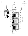
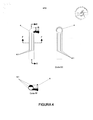
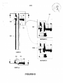
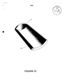
Para a adequada compreensão do “SISTEMA SEPARADOR DE SÓLIDOS, ÁGUA E ÓLEOS DESTINADO AO TRATAMENTO DE ÁGUAS RESIDUAIS” são apresentadas as figuras anexas, onde: FIGURA 1 - Representa vista em planta, corte BB horizontal, do sistema. O Detalhe 1 representa o dispositivo desnivelador com duas conexões em “T” para retenção de micropartículas. FIGURA 2 - Representa vista vertical, corte AA, do sistema. O Detalhe 2 representa o dispositivo desnivelador com duas conexões em “T” para retenção de micropartículas. FIGURA 3 - Representa vista em planta, corte DD, e corte CC vertical da caixa de sólidos, apresentando um crivo longo assentado em sua saída, permitindo a passagem da água e do óleo para a caixa subseqüente, que é a caixa de tranquilização. FIGURA 4 - Representa vista lateral do crivo longo, e cortes EE vertical e FF horizontal. FIGURA 5 - Representa vista em planta, corte GG e corte HH vertical da caixa de tranquilização que apresenta em seu bojo o dispositivo desnivelador. FIGURA 6 - Representa vista lateral, corte II vertical e corte JJ horizontal do dispositivo desnivelador composto de duas conexões em “T” acopladas a um prolongamento, opcionalmente um “T” e um joelho 90° acoplados ao prolongamento. Os Detalhes 3 e 4 representam vistas do dispositivo desnivelador mostrando que opcionalmente poderá ser utilizado um duplo “T” ou um “T” e um joelho 90°. FIGURA 7 - Representa vista em planta, corte LL e corte vertical KK, da caixa sifonada dotada de septo com visita, resultando em câmara receptora e câmara vertedoura, a qual contém a calha vertedoura em curva reversa, mostrando o desnível de 2,5cm entre os vertedouros. FIGURA 8 - Representa vista em perspectiva inferior do septo com visita. FIGURA 9 - Representa vista em corte longitudinal MM e em corte transversal NN do septo com visita. FIGURA 10 - Representa vista em perspectiva da calha vertedoura em curva reversa. FIGURA 11 - Representa vista superior da calha vertedoura em curva reversa. FIGURA 12 - Representa vista lateral da calha vertedoura em curva reversa. FIGURA 13 - Representa vista em perspectiva inferior da variante construtiva do septo com visitaFor the proper understanding of the “SOLID, WATER AND OIL SEPARATOR SYSTEM FOR THE TREATMENT OF WASTE WATER” the attached figures are presented, where: FIGURE 1 - Represents plan view, horizontal BB section, of the system.
De acordo com as figuras 1 e 2, a forma de realização preferida do “SISTEMA SEPARADOR DE SÓLIDOS, ÁGUA E ÓLEOS DESTINADO AO TRATAMENTO DE ÁGUAS RESIDUAIS” compreende um conjunto de quatro caixas (1) principais: a caixa de sólidos (1.1), a caixa de tranquilização (1.2), a caixa sifonada (1.3) e a caixa de óleo (1.4), interligadas pordutos reguladores de vazão (3.2), sendo a caixa sifonada (1.3) interligada à caixa de coleta de amostras (2) através do duto (3.3) de saída de água.According to figures 1 and 2, the preferred embodiment of the "SOLID, WATER AND OIL SEPARATOR SYSTEM FOR THE TREATMENT OF WASTE WATER" comprises a set of four main boxes (1): the solid box (1.1), the still box (1.2), the siphon box (1.3) and the oil box (1.4), connected by flow regulating ducts (3.2), the siphon box (1.3) being connected to the sample collection box (2) through the water outlet duct (3.3).
De acordo com as figuras 1 a 4, a caixa de sólidos (1.1) recebe pela tubulação (3.1) a água bruta residuária (a) e é dotada em seu bojo de um crivo longo (4) assentado em sua saída no duto regulador de vazão (3.2), que pelas suas frestas verticais (4.1) permite a passagem do efluente líquido, composto de águas (a), óleos (b), emulsões (e), detergentes, etc., para a caixa de tranquilização (1.2) e retém os materiais sólidossobrenadantes (d). Além das funções de passagem de líquido e de retenção de sólidos, o crivo longo (4) acusa o momento mais adequado à operação de limpeza da caixa de sólidos (1.1), que ocorre quando os sólidos sedimentados (f) atingem a extremidade inferior do crivo longo (4) provocando o refluxo da vazão. A caixa de sólidos (1.1) retém em seu fundo todos os materiais (f) de densidades maiores que a da água, como terra, areia, cascalho, etc.According to figures 1 to 4, the solid box (1.1) receives the raw waste water (a) from the pipe (3.1) and is provided with a long sieve (4) at its outlet in the regulating duct of flow (3.2), which through its vertical cracks (4.1) allows the passage of liquid effluent, composed of water (a), oils (b), emulsions (e), detergents, etc., to the tranquilization box (1.2) and retains the supernatant solid materials (d). In addition to the liquid passage and solids retention functions, the long sieve (4) shows the most suitable moment for cleaning the solids box (1.1), which occurs when the sedimented solids (f) reach the lower end of the long sieve (4) causing reflux of the flow. The solid box (1.1) retains on its bottom all materials (f) with densities greater than that of water, such as earth, sand, gravel, etc.
Os dutos reguladores de vazão (3.2) de interligação entre as caixas foram projetados com diâmetros inferiores ao diâmetro do duto de entrada (3.1) no sistema, que comumente são de 100mm, com o propósito de funcionarem como condutos forçados e, consequentemente, induzirem perdas de carga, que provocam o refluxo e limitam as vazões, regulando o fluxo para que a lâmina d’agua sobre a calha vertedoura em curva reversa (6) fique em torno de 1cm e não ultrapasse os 2,5cm referentes ao desnível entre o vertedor de óleo, que é a geratriz inferior do duto (3.2) da caixa sifonada (1.3), e o vertedor de água, que é a superfície da dobra recurvada (6.1) da calha vertedoura em curva reversa (6).The flow regulating ducts (3.2) of interconnection between the boxes were designed with diameters smaller than the diameter of the inlet duct (3.1) in the system, which are usually 100mm, with the purpose of functioning as forced ducts and, consequently, inducing losses load, which cause reflux and limit flow, regulating the flow so that the water depth over the spillway in a reverse curve (6) is around 1cm and does not exceed 2.5cm referring to the unevenness between the spillway of oil, which is the lower generatrix of the duct (3.2) of the siphoned box (1.3), and the water spillway, which is the curved fold surface (6.1) of the spillway chute in reverse curve (6).
De acordo com as figuras 5 e 6, a caixa de tranquilização (1.2) apresenta em seu bojo um dispositivo desnivelador (5) formado por duas conexões em “T” (5.1) e (5.2), sendo a conexão (5.2) em “T” DN VJ soldada no interior da conexão (5.1) em “T” DN 50 mm, ambas acopladas a um tubo prolongador (5.3). Também opcionalmente, de acordo com o Detalhe 4, o dispositivo desnivelador (5) pode se constituir pela soldagem de uma conexão em “T” DN 50mm (5.1) com outra conexão curva 90° “joelho” DN !ó” (5.2a), também acopladas ao tubo prolongador (5.3). O dispositivo desnivelador (5) foi projetado para proporcionar a formação de uma fina camada de óleo (b), necessária e suficiente para que as emulsões e gotículas de óleo (e) sejam retidas no bojo da caixa de tranquilização (1.2) e não extravasem para a caixa sifonada (1.3) subsequente. O dispositivo desnivelador (5) permite a passagem para a caixa subsequente (1.3) apenas do óleo (b) estabilizado e da água (c) decantada, retendo as micropartículas e as emulsões (e) de óleo/água no interior da caixa de tranquilização (1.2),onde as mesmas se aglutinam, se coagulam, se coalescem e se transformam em óleo (b) estável.According to figures 5 and 6, the stilling box (1.2) has a leveling device (5) formed by two “T” connections (5.1) and (5.2), the connection (5.2) being in “ T ”DN VJ welded inside the connection (5.1) in“ T ”DN 50 mm, both coupled to an extension tube (5.3). Also optionally, according to
De acordo com as figuras 1 e 2 e 7 a 9, o óleo (b) estabilizado e a água (c) decantada fluem através da ligação (3.2) para a caixa sifonada (1.3), onde, separadamente, são conduzidos, pela atuação conjunta do septo com visita (7) e da calha vertedoura em curva reversa (6), sendo o óleo (b) para a caixa de óleo (1.4) e a água (c) para a caixa de coleta (2) de amostras. A caixa sifonada (1.3) apresenta um septo com visita (7) que é dotado de um tampão (8), que processa em sua câmara receptora (1.3a) a separação da água e do óleo (b) estabilizado, encaminhando este para a caixa de óleos (1.4) e a água para a câmara vertedoura (1.3b), a qual contém a calha vertedoura em curva reversa (6).According to figures 1 and 2 and 7 to 9, the oil (b) stabilized and the water (c) decanted flow through the connection (3.2) to the siphon box (1.3), where, separately, they are guided, by acting joint of the septum with visit (7) and the spillway chute in reverse curve (6), with oil (b) for the oil box (1.4) and water (c) for the sample collection box (2). The siphon box (1.3) has a visiting septum (7) that is equipped with a plug (8), which processes in its receiving chamber (1.3a) the separation of the water and the stabilized oil (b), directing it to the oil box (1.4) and water for the spillway chamber (1.3b), which contains the spillway chute in reverse curve (6).
De acordo com as figuras 8 e 9, o septo (7), com forma de realização preferida em seção em calha trapezoidal, ou também, de acordo com a figura 13 em calha curva (7.1), é dotado de visita (8) em sua seção superior, que deverá ser inclinada para evitar o acúmulo de resíduos, permitir o acesso, inspeção, operações de lavagem e desobstrução do interior da câmara vertedoura (1.3b), da calha vertedoura em curva reversa (6) e da tubulação de saída (3.3).According to figures 8 and 9, the septum (7), with a preferred embodiment in a trapezoidal channel section, or also, according to figure 13 in curved channel (7.1), is equipped with a visit (8) in its upper section, which must be inclined to avoid the accumulation of residues, allow access, inspection, washing and unblocking operations from inside the spillway chamber (1.3b), the spillway chute in reverse curve (6) and the outlet pipe (3.3).
De acordo com as figuras 10 a 12, a calha vertedoura em curva reversa (6) apresenta dobra recurvada (6.1) em sua seção inferior e corte em “L” em sua seção superior, resultando em um vertedor com um comprimento mais alongado, com a finalidade de evitar a formação de grande lâmina d’água na calha vertedoura em curva reversa (6), acoplada ao duto da saída (3.3), de modo que a lâmina d’água sobre a mesma seja a mínima possível e não supere os tradicionalmente adotados 2,5cm da diferença entre o nível da geratriz inferior do vertedor de óleo (3.2) e o nível da dobra recurvada (6.1) da calha vertedoura de água (6), o que provocaria derramamento de água na caixa de óleos (1.4) devido à pequena diferença de nível existente entre a saída de óleo e a saída de água. O formato do vertedor (6.1) da calha vertedoura (6) poderá apresentar variações, desde que mantida sua função de alongar o vertedor para o controle da altura dalâmina cTágua sobre o mesmo.According to figures 10 to 12, the spillway chute in reverse curve (6) has a curved fold (6.1) in its lower section and a “L” cut in its upper section, resulting in a spillway with a more elongated length, with the purpose of avoiding the formation of a large water depth in the spillway chute in reverse curve (6), coupled to the outlet duct (3.3), so that the water depth over it is as little as possible and does not exceed the traditionally adopted 2.5cm of the difference between the level of the lower spill of the oil spill (3.2) and the level of the curved bend (6.1) of the water spillway (6), which would cause water to spill into the oil box (1.4 ) due to the small difference in level between the oil outlet and the water outlet. The shape of the spillway (6.1) of the spillway chute (6) may vary, as long as its function of elongating the spillway is maintained to control the height of the blade over the water.
Evidentemente, algumas alterações poderão ser introduzidas no lay-out do sistema, na modulação e capacidade das caixas, na equalização do dimensionamento dos dutos de entrada/saída e interligações, 5 sem a perda das novidades apresentadas.Obviously, some changes may be introduced in the system layout, in the modulation and capacity of the boxes, in the equalization of the dimensioning of the inlet / outlet ducts and interconnections, 5 without losing the novelties presented.
Claims (7)
Priority Applications (1)
| Application Number | Priority Date | Filing Date | Title |
|---|---|---|---|
| BRPI1002049-7A BRPI1002049B1 (en) | 2010-07-26 | 2010-07-26 | solids, water and oil separator system for wastewater treatment |
Applications Claiming Priority (1)
| Application Number | Priority Date | Filing Date | Title |
|---|---|---|---|
| BRPI1002049-7A BRPI1002049B1 (en) | 2010-07-26 | 2010-07-26 | solids, water and oil separator system for wastewater treatment |
Publications (2)
| Publication Number | Publication Date |
|---|---|
| BRPI1002049A2 BRPI1002049A2 (en) | 2012-05-22 |
| BRPI1002049B1 true BRPI1002049B1 (en) | 2020-11-17 |
Family
ID=46087847
Family Applications (1)
| Application Number | Title | Priority Date | Filing Date |
|---|---|---|---|
| BRPI1002049-7A BRPI1002049B1 (en) | 2010-07-26 | 2010-07-26 | solids, water and oil separator system for wastewater treatment |
Country Status (1)
| Country | Link |
|---|---|
| BR (1) | BRPI1002049B1 (en) |
-
2010
- 2010-07-26 BR BRPI1002049-7A patent/BRPI1002049B1/en active IP Right Grant
Also Published As
| Publication number | Publication date |
|---|---|
| BRPI1002049A2 (en) | 2012-05-22 |
Similar Documents
| Publication | Publication Date | Title |
|---|---|---|
| KR100549738B1 (en) | Vortex separator for stormwater inflowing to center | |
| JP4395190B2 (en) | Separation apparatus and separation method | |
| ES2234893T3 (en) | COMBINED TANK DEGASIFICATION AND FLOATING. | |
| AU2008279378B2 (en) | Separator tank | |
| CA1122538A (en) | Separator for two immiscible liquids | |
| JP2016526482A (en) | Pressure levitation device | |
| KR100605267B1 (en) | Rainwater controlling device | |
| US5296150A (en) | Water oil separator | |
| JPH0326082B2 (en) | ||
| CN206359279U (en) | Highway oily-water seperating equipment | |
| JP3546359B2 (en) | Oil-water separator | |
| US11679343B2 (en) | Inclined linear multi-phase gravity separation system | |
| KR100825944B1 (en) | Structure for treating rainwater | |
| CN107522310A (en) | Not agent-feeding treatment oil-polluted water re-injection technique | |
| KR20090112501A (en) | Apparatus for Treatment of First Flush Rainfall | |
| US20060283814A1 (en) | Gravitational separator and apparatus for separating floating particulate and volatile liquids from a stormwater stream adaptable for inline usage | |
| US20110147302A1 (en) | Oil/Water Separator | |
| US20060219629A1 (en) | Oil and water separator | |
| US9963358B2 (en) | Oil stop valve assembly | |
| KR101130569B1 (en) | Apparatus for eliminating non-point contaminant of which the filtering efficiency is improved | |
| KR200398999Y1 (en) | Vortex separator for stormwater inflowing to center | |
| KR200366226Y1 (en) | Hydrocyclone type separator | |
| BRPI1002049B1 (en) | solids, water and oil separator system for wastewater treatment | |
| RU2579847C2 (en) | Device for separation of mix of light fluid and water and method to this end | |
| JP2939426B2 (en) | Oil-water separation equipment |
Legal Events
| Date | Code | Title | Description |
|---|---|---|---|
| B03A | Publication of a patent application or of a certificate of addition of invention [chapter 3.1 patent gazette] | ||
| B06F | Objections, documents and/or translations needed after an examination request according [chapter 6.6 patent gazette] | ||
| B25A | Requested transfer of rights approved |
Owner name: ARTEFACIL INDUSTRIA E COMERCIO LTDA (BR/MG) |
|
| B65X | Notification of requirement for priority examination of patent application | ||
| B65Z | Priority examination of the patent application refused (request does not comply with dec. 132/06 of 20061117) | ||
| B06V | Preliminary requirement: patent application procedure suspended [chapter 6.22 patent gazette] | ||
| B06A | Patent application procedure suspended [chapter 6.1 patent gazette] | ||
| B09A | Decision: intention to grant [chapter 9.1 patent gazette] | ||
| B16A | Patent or certificate of addition of invention granted [chapter 16.1 patent gazette] |
Free format text: PRAZO DE VALIDADE: 10 (DEZ) ANOS CONTADOS A PARTIR DE 17/11/2020, OBSERVADAS AS CONDICOES LEGAIS. |
|
| B22O | Other matters related to patents and certificates of addition of invention: legal action concerning patent |
Free format text: "INPI NO 52402.001968/2022-48 ORIGEM: JUIZO FEDERAL DA 13A VF DO RIO DE JANEIRO (TRF2) PROCESSO NO: 5031009-85.2021.4.02.5101 NULIDADE DA PATENTE DE INVENCAO COM PEDIDO DE ANTECIPACAO DE TUTELA AUTOR: PRE-MOLDADOS SAMPAIO EIRELI-EPP REU(S): ARTEFACIL INDUSTRIA E COMERCIO LTDA E INPI ? INSTITUTO NACIONAL DA PROPRIEDADE INDUSTRIAL" |