BRPI0922387B1 - filter elements and compressed air filters to separate foreign bodies from a compressed air stream - Google Patents
filter elements and compressed air filters to separate foreign bodies from a compressed air stream Download PDFInfo
- Publication number
- BRPI0922387B1 BRPI0922387B1 BRPI0922387-8A BRPI0922387A BRPI0922387B1 BR PI0922387 B1 BRPI0922387 B1 BR PI0922387B1 BR PI0922387 A BRPI0922387 A BR PI0922387A BR PI0922387 B1 BRPI0922387 B1 BR PI0922387B1
- Authority
- BR
- Brazil
- Prior art keywords
- sealing
- housing
- filter
- filter element
- face
- Prior art date
Links
Images


Classifications
-
- B—PERFORMING OPERATIONS; TRANSPORTING
- B01—PHYSICAL OR CHEMICAL PROCESSES OR APPARATUS IN GENERAL
- B01D—SEPARATION
- B01D46/00—Filters or filtering processes specially modified for separating dispersed particles from gases or vapours
- B01D46/24—Particle separators, e.g. dust precipitators, using rigid hollow filter bodies
- B01D46/2403—Particle separators, e.g. dust precipitators, using rigid hollow filter bodies characterised by the physical shape or structure of the filtering element
- B01D46/2411—Filter cartridges
- B01D46/2414—End caps including additional functions or special forms
-
- B—PERFORMING OPERATIONS; TRANSPORTING
- B01—PHYSICAL OR CHEMICAL PROCESSES OR APPARATUS IN GENERAL
- B01D—SEPARATION
- B01D46/00—Filters or filtering processes specially modified for separating dispersed particles from gases or vapours
- B01D46/0002—Casings; Housings; Frame constructions
- B01D46/0004—Details of removable closures, lids, caps or filter heads
-
- B—PERFORMING OPERATIONS; TRANSPORTING
- B01—PHYSICAL OR CHEMICAL PROCESSES OR APPARATUS IN GENERAL
- B01D—SEPARATION
- B01D46/00—Filters or filtering processes specially modified for separating dispersed particles from gases or vapours
- B01D46/0039—Filters or filtering processes specially modified for separating dispersed particles from gases or vapours with flow guiding by feed or discharge devices
-
- B—PERFORMING OPERATIONS; TRANSPORTING
- B01—PHYSICAL OR CHEMICAL PROCESSES OR APPARATUS IN GENERAL
- B01D—SEPARATION
- B01D2271/00—Sealings for filters specially adapted for separating dispersed particles from gases or vapours
- B01D2271/02—Gaskets, sealings
- B01D2271/027—Radial sealings
Abstract
ELEMENTO DE FILTRO E FILTRO DE AR COMPRIMIDO PARA SEPARAR MATÉRIA ESTANHA DE UM FLUXO DE AR COMPRIMIDO. A presente invenção fornece um filtro de ar (1) e um elemento de filtro (5) que é para separar corpos estranhos de um fluxo de ar comprimido e que tem uma parte inferior do elemento (6), uma parte superior do elemento (7) que tem uma parte de gargalo (13) que forma um primeiro canal (9) e uma parte do coIar (14) que é construída para se estender pelo menos parcialmente em volta da parte de gargalo (13) e que é conectada a parte do gargalo (13) para formar um segundo canal de fluxo (10), e um meio filtrante (8) que é conectado em vedação a parte inferior do elemento (6) e a parte superior do elemento (7) a fim de formar um caminho de fluxo de gás entre o primeiro canal de fluxo (9) e o segundo canal de fluxo (10) através do meio filtrante (8), em que a parte do colar (14) tem uma face de contato (16), que é fornecida pelo menos parcialmente na periferia externa e que afunila na direção da parte inferior do elemento (6), a fim de receber um anel de vedação associado (22) de uma maneira que uma força que atua de forma substancialmente axial no (...).FILTER ELEMENT AND COMPRESSED AIR FILTER TO SEPARATE TIN MATERIAL FROM A COMPRESSED AIR FLOW. The present invention provides an air filter (1) and a filter element (5) which is for separating foreign bodies from a compressed air flow and which has a lower part of the element (6), an upper part of the element (7 ) which has a neck part (13) which forms a first channel (9) and a collar part (14) which is constructed to extend at least partially around the neck part (13) and which is connected to the part. of the neck (13) to form a second flow channel (10), and a filter means (8) which is sealingly connected to the lower part of the element (6) and the upper part of the element (7) to form a gas flow path between the first flow channel (9) and the second flow channel (10) through the filter medium (8), wherein the collar portion (14) has a contact face (16), which is provided at least partially on the outer periphery and tapers towards the bottom of the element (6) in order to receive an associated sealing ring (22) in a manner that ue a force that acts substantially axially on (...).
Description
[001] A presente invenção refere-se a um elemento de filtro e um filtro de ar comprimido para separar corpos estranhos de um fluxo de ar comprimido.[001] The present invention relates to a filter element and a compressed air filter to separate foreign bodies from a compressed air stream.
[002] Embora a presente invenção possa ser usada em quaisquer sistemas de filtro, a presente invenção e o problema endereçado por ela são explicados em maiores detalhes com relação a um filtro de ar comprimido. Entretanto, a noção da presente invenção também pode ser usada, por exemplo, em um separador de fluido ou algo semelhante.[002] Although the present invention can be used in any filter systems, the present invention and the problem addressed by it are explained in greater detail with respect to a compressed air filter. However, the notion of the present invention can also be used, for example, in a fluid separator or the like.
[003] Filtros de ar comprimido convencionais geralmente com preendem uma carcaça de duas peças que tem uma parte superior da carcaça e uma tampa da carcaça que são ambas enroscadas juntas ou conectadas uma a outra por meio de uma porca de tampa ou fechamento tipo baioneta. A parte superior da carcaça geralmente tem um canal de entrada e um canal de descarga em lados diametralmente opostos. O canal de entrada abre ou centralmente dentro de um elemento de filtro substituível cilíndrico-oco, que é introduzido ou enroscado dentro da parte superior da carcaça em uma maneira vedante, ou dentro do espaço anelar entre o elemento de filtro e a carcaça de filtro. Consequentemente, o canal de descarga se estende ou a partir do espaço anelar ou a partir do interior do elemento de filtro dependendo de se o elemento de filtro é para ser sujeitado ao fluxo em uma direção para fora ou em uma direção para dentro. Portanto, a direção do fluxo no filtro é geralmente fixada após ajustar e não pode ser mudada na posição ajustada. O campo de aplicação do filtro também é geralmente fixado ao mesmo tempo em que a direção do fluxo. Quando é filtrada poeira, o elemento de filtro é geralmente sujeito a fluxo a partir do lado externo e é sujeito a fluxo a partir do lado interno a fim de separar ar comprimido condensado durante filtração de coalescência.[003] Conventional compressed air filters generally comprise a two-piece housing that has an upper housing part and a housing cover that are both threaded together or connected to each other by means of a cap nut or bayonet-type closure. The upper part of the housing usually has an inlet channel and an outlet channel on diametrically opposite sides. The inlet channel opens either centrally into a hollow-cylindrical replaceable filter element, which is inserted or threaded into the top of the housing in a sealing manner, or into the annular space between the filter element and the filter housing. Consequently, the discharge channel extends either from the annular space or from the interior of the filter element depending on whether the filter element is to be subjected to flow in an outward direction or in an inward direction. Therefore, the direction of flow in the filter is usually fixed after adjusting and cannot be changed in the adjusted position. The filter's field of application is also generally fixed at the same time as the flow direction. When dust is filtered, the filter element is generally flown from the outside and is flown from the inside in order to separate condensed compressed air during coalescence filtration.
[004] Os elementos de filtro são geralmente partes de manuten ção que tem que ser mudados após um dado tempo devido à ocorrência de contaminação. O elemento de filtro geralmente compreende uma parte inferior do elemento, uma parte superior do elemento e um meio do filtro que é conectado de modo vedante, usualmente ligado adesivamente, a parte inferior do elemento e a parte superior do elemento a fim de formar um caminho de fluxo de gás predeterminado através do meio do filtro.[004] Filter elements are generally maintenance parts that have to be changed after a given time due to the occurrence of contamination. The filter element generally comprises a lower part of the element, an upper part of the element and a means of the filter which is sealingly connected, usually adhesively bonded, to the lower part of the element and the upper part of the element in order to form a path of predetermined gas flow through the filter medium.
[005] Em adição a uma conexão de vedação entre a parte supe rior do elemento do filtro e a parte superior da carcaça da carcaça do filtro, uma vedação da carcaça também tem que ser fornecida entre a parte superior da carcaça e a tampa da carcaça da carcaça do filtro a fim de fechar a carcaça do filtro após montar de uma maneira bem vedada com respeito ao ambiente e consequentemente não permitir que qualquer ar comprimido seja descarregado. Aquela vedação da carcaça é geralmente fornecida separadamente do elemento de filtro e, de acordo com a técnica anterior, é usualmente inserida na forma de um anel de vedação atuando radialmente em um recesso para o anel de vedação na parte superior da carcaça ou na tampa da carcaça da carcaça do filtro.[005] In addition to a sealing connection between the top of the filter element and the top of the filter housing housing, a housing seal also has to be provided between the top of the housing and the housing cover of the filter housing in order to close the filter housing after mounting in a well-sealed manner with respect to the environment and consequently not allow any compressed air to be discharged. That housing seal is generally supplied separately from the filter element and, according to the prior art, is usually inserted in the form of a sealing ring acting radially in a recess for the sealing ring in the upper part of the housing or in the cover of the housing. filter housing housing.
[006] A publicação EP 1.343.574 B1 descreve um filtro de ar comprimido, no qual uma vedação é construída entre a parte superior da carcaça e a tampa da carcaça do filtro por meio de um anel de vedação radial. O anel de vedação é inserido em um recesso radial correspondente na tampa da carcaça e junta uma face externa cilíndrica da parte superior da carcaça em uma maneira vedante na posição fechada a fim de garantir vedação radial.[006] EP publication 1,343,574 B1 describes a compressed air filter, in which a seal is built between the upper part of the housing and the cover of the filter housing by means of a radial sealing ring. The gasket is inserted into a corresponding radial recess in the housing cover and joins a cylindrical outer face of the housing top in a sealing manner in the closed position to ensure radial sealing.
[007] Quando esta vedação radial como descrita na EP 1.343.574 B1 é usada, uma força de atrito substancial ou um momento de atrito substancial tem que desvantajosamente ser superado pelo menos na fase final da operação de fechamento devido ao anel de vedação que é estabelecido radialmente. Também é desvantajoso que o atrito do anel de vedação, que é deformado pela pressão interna de longo prazo na carcaça do filtro e que é pressionado dentro da superfície áspera, tenha que ser superado nestas construções com uma vedação radial durante a operação de abertura para remover o elemento de filtro, pelo que são necessárias grandes forças ou torques de acionamento, em particular no caso de diâmetros relativamente grandes das tampas de carcaça. Particularmente no início da operação de abertura, tem que ser aplicadas forças de separação substanciais ou um momento de separação substancial que são substancialmente maiores do que a força de montagem ou momento de montagem. A partir de um tamanho de carcaça específico, consequentemente, a montagem e particularmente a desmontagem de um elemento de filtro para dentro ou fora da carcaça de filtro geralmente não pode mais ser executada manualmente, mas em vez disso através do uso de uma ferramenta adicional de uma maneira desvantajosa.[007] When this radial seal as described in EP 1,343,574 B1 is used, a substantial frictional force or a substantial frictional moment has to disadvantageously be overcome at least in the final phase of the closing operation due to the sealing ring being established radially. It is also disadvantageous that seal ring friction, which is deformed by the long-term internal pressure in the filter housing and which is pressed into the rough surface, has to be overcome in these constructions with a radial seal during the opening operation to remove the filter element, whereby large driving forces or torques are required, in particular in the case of relatively large diameters of the housing covers. Particularly at the beginning of the opening operation, substantial separating forces or a substantial separating moment have to be applied which are substantially greater than the assembling force or assembling moment. From a specific housing size, therefore, the assembly and particularly the disassembly of a filter element into or out of the filter housing generally can no longer be performed manually, but instead through the use of an additional tool. a disadvantageous way.
[008] A Publicação DE 103.09.428. B4 descreve um filtro de ar comprimido, no qual uma pluralidade de vedações de carcaça são localizadas no lado terminal entre a tampa da carcaça e a parte superior da carcaça do filtro.[008] The Publication DE 103.09.428. B4 describes a compressed air filter, in which a plurality of housing seals are located on the terminal side between the housing cover and the upper part of the filter housing.
[009] A fim de acomodar a vedação embora o diâmetro interno da tampa da carcaça permaneça o mesmo, esta construção precisa de um diâmetro maior da tampa da carcaça e da parte superior da carcaça na região de vedação assim faces maiores que são sujeitas a pressão e forças maiores são produzidas ao contrário das vedações radiais. A fim de simplificar a montagem ou de evitar danos as vedações durante a operação de montagem, é desvantajosamente necessário evitar movimento rotacional das faces de vedação da tampa da carca- ça em relação às faces de vedação da parte superior da carcaça durante a operação de fechamento. Consequentemente, não é possível usar uma rosca de fechamento simples entre a parte superior da carcaça e a tampa da carcaça. Em vez disso, têm que ser construídas soluções mais complexas, por exemplo, na forma de uma porca de tampa, com a qual a tampa da carcaça é puxada de encontro à parte superior da carcaça, como descrito, por exemplo, nos documentos DE 103.09.428 B4 ou DE 356.41.370.[009] In order to accommodate the seal although the inner diameter of the housing cover remains the same, this construction needs a larger diameter of the housing cover and the top of the housing in the sealing region so larger faces that are subjected to pressure and higher forces are produced unlike radial seals. In order to simplify the assembly or to avoid damage to the seals during the assembly operation, it is disadvantageously necessary to avoid rotational movement of the sealing faces of the housing cover in relation to the sealing faces of the upper part of the housing during the closing operation . Consequently, it is not possible to use a single closure thread between the top of the housing and the housing cover. Instead, more complex solutions have to be constructed, for example in the form of a cap nut, with which the housing cap is pulled against the upper part of the housing, as described, for example, in documents DE 103.09 .428 B4 or DE 356.41.370.
[010] Outro problema de tais vedações dispostas axialmente é constituído por a vedação ser fixada à parte superior do elemento. Os anéis de vedação atuando axialmente não podem ser retidos prontamente na parte superior do elemento de uma maneira de travamento positivo. Vedações que engatam materialmente tais como, por exemplo,vedações de elastômero que são moldadas por injeção durante o processo de produção podem novamente apresentar problemas com respeito à função de vedação porque, ao contrário de uma vedação de anel de vedação, a vedação não fia aplicada na fresta de vedação como um resultado da diferença de pressão. Portanto, pode ser absolu-tamente o caso em que o pré-tensionamento de montagem diminui ao longo do tempo devido a ocorrências de deformação e ajustamento do material de vedação e a vedação já não funciona confiavelmente.[010] Another problem of such axially arranged seals is constituted by the seal being fixed to the upper part of the element. Axially acting O-rings cannot readily be retained on top of the element in a positive locking manner. Seals that engage materially such as, for example, elastomer seals that are injection molded during the production process can again present problems with respect to the sealing function because, unlike a gasket seal, the seal does not get applied at the sealing gap as a result of the pressure difference. Therefore, it can absolutely be the case that the assembly pre-strain decreases over time due to occurrences of deformation and adjustment of the sealing material and the sealing no longer works reliably.
[011] Desvantajosamente, vedações especiais na forma de uma vedação que engatam de uma maneira semelhante a U em torno do colar da parte superior do elemento, como descrito, por exemplo, nas publicações US 4.721.563, requer uma quantidade relativamente grande de espaço de construção e um alto nível de complexidade de construção e podem se tornar s de uma maneira indesejável se uma pretensão de montagem definida não puder ser mantida ou se a vedação não for aplicada a fresta como um resultado da diferença de pressão.[011] Disadvantageously, special seals in the form of a seal that engage in a U-like manner around the collar of the upper part of the element, as described, for example, in US publications 4,721,563, require a relatively large amount of space of construction and a high level of construction complexity and can become undesirable if a defined mounting pretense cannot be maintained or if the seal is not applied to the gap as a result of the pressure difference.
[012] Quando os elementos de filtro contaminados são desmon- tados, outra desvantagem de muitas construções de filtro conhecidas é que o elemento de filtro não é retido axialmente na tampa da carcaça, mas em vez disso ainda permanece conectado a parte superior da carcaça ou fica retido pela vedação entre a parte superior do elemento e a parte superior da carcaça após a tampa da carcaça ser afrouxada. A fim de desmontar o elemento de filtro neste caso, portanto, ou a tampa da carcaça geralmente tem que ser axialmente retirada de todo o tamanho do elemento de filtro ou o elemento de filtro tem que ser afrouxado a mão através da fresta entre a parte superior da carcaça e a tampa da carcaça com a tampa da carcaça sendo parcialmente levantada. No primeiro caso, a exigência de espaço é desvantajosa e, no segundo caso, o contato com o elemento de filtro contaminado é desvantajoso e o manuseio para o usuário é extremamente complicado porque é necessário simultaneamente segurar a tampa da carcaça e afrouxar o elemento de filtro.[012] When contaminated filter elements are disassembled, another disadvantage of many known filter constructions is that the filter element is not axially retained in the housing cover, but instead still remains attached to the upper housing or is retained by the seal between the top of the element and the top of the housing after the housing cover is loosened. In order to disassemble the filter element in this case, therefore, either the housing cover generally has to be axially removed from the entire size of the filter element or the filter element has to be loosened by hand through the gap between the top. of the housing and the housing cover with the housing cover being partially lifted. In the first case, the space requirement is disadvantageous and, in the second case, contact with the contaminated filter element is disadvantageous and handling for the user is extremely complicated because it is necessary to simultaneously hold the housing cover and loosen the filter element .
[013] Outra desvantagem de algumas construções de filtro co nhecidas que tem uma vedação de carcaça ajustada a parte superior do elemento é que o elemento é suportado por meio da vedação da carcaça em uma direção axial com respeito à carcaça do filtro. Devido à mídia variável que flui através do elemento de filtro, diferenças variáveis de pressão e consequentemente mudanças de forças axiais atuam na vedação da carcaça, pelo que a mesma pode ser danificada e a operação de vedação da mesma pode ser prejudicada. O mesmo efeito pode ocorrer devido ao ajustamento da vedação sob diferenças de pressão ou forças axiais que atuam por um longo período de tempo.[013] Another disadvantage of some known filter constructions that have a housing seal fitted to the top of the element is that the element is supported by means of the housing seal in an axial direction with respect to the filter housing. Due to the variable media that flows through the filter element, variable pressure differences and consequently changes in axial forces act on the casing seal, whereby the casing can be damaged and the casing sealing operation impaired. The same effect can occur due to the adjustment of the seal under pressure differences or axial forces acting for a long period of time.
[014] Na técnica anterior, por exemplo, na publicação US 4.721.563, é fornecido um suporte axial para o elemento de filtro na parte inferior do elemento a fim de resolver aquele problema. Entretanto, isto é desvantajoso na operação da vedação da carcaça devido a tolerâncias longitudinais do elemento de filtro, da parte superior da carcaça e da tampa da carcaça.[014] In the prior art, for example, in US publication 4,721,563, an axial support for the filter element is provided at the bottom of the element in order to solve that problem. However, this is disadvantageous in the operation of the housing seal due to longitudinal tolerances of the filter element, the upper housing part and the housing cover.
[015] Um objetivo da presente invenção é superar as desvanta gens mencionadas acima e fornecer um elemento de filtro que seja melhorado com relação à técnica anterior e um filtro de ar comprimido que seja melhorado em relação à técnica anterior.[015] An object of the present invention is to overcome the disadvantages mentioned above and provide a filter element that is improved over the prior art and a compressed air filter that is improved over the prior art.
[016] Este objetivo é alcançado por um elemento de filtro e por um filtro de ar comprimido que têm as características da presente invenção.[016] This objective is achieved by a filter element and a compressed air filter that have the characteristics of the present invention.
[017] A noção que forma a base da presente invenção envolve fornecer um elemento de filtro que é para separar corpos estranhos de um fluxo de ar comprimido e que tem uma parte inferior do elemento; uma parte superior do elemento que tem uma parte de gargalo que forma um primeiro canal de fluxo e uma parte de colar que é construída para se estender pelo menos parcialmente em torno a parte do gargalo e que é conectada à parte do gargalo para formar um segundo canal de fluxo; e um meio filtrante que é conectado de modo vedante com a parte inferior do elemento e a parte superior do elemento a fim de formar um caminho de fluxo de gás entre o primeiro canal de fluxo e o segundo canal de fluxo através do meio filtrante; em que a parte de colar tem uma face de contato, que é fornecida pelo menos parcialmente na periferia e que afunila na direção da parte inferior do elemento, a fim de receber um elemento de vedação associado de tal maneira que uma força que atua de forma substancialmente axial no elemento de vedação a partir da parte inferior do elemento acarreta expansão radial do elemento de vedação ao longo da face de contato.[017] The notion that forms the basis of the present invention involves providing a filter element that is to separate foreign bodies from a stream of compressed air and that has a lower part of the element; an upper part of the element having a neck part which forms a first flow channel and a collar part which is constructed to extend at least partially around the neck part and which is connected to the neck part to form a second flow channel; and a filter means that is sealingly connected to the bottom of the element and the top of the element to form a gas flow path between the first flow channel and the second flow channel through the filter means; wherein the collar part has a contact face, which is provided at least partially at the periphery and which tapers towards the lower part of the element, in order to receive an associated sealing element such that a force acting so substantially axially in the sealing element from the bottom of the element causes radial expansion of the sealing element along the contact face.
[018] A presente invenção é adicionalmente baseada a este res peito na noção de fornecer um filtro de ar comprimido que é para separar corpos estranhos de um fluxo de ar comprimido e que tem o elemento de filtro descrito acima de acordo com a invenção; e uma carcaça de filtro que recebe o elemento de filtro de uma maneira vedante e que tem uma parte superior da carcaça que tem uma primeira face de vedação, que é associada com o elemento de vedação do elemento de filtro e que é fornecida pelo menos parcialmente na periferia interna, e uma tampa da carcaça que tem uma segunda face de vedação que é associada com o elemento de vedação do elemento de filtro e que é fornecida pelo menos parcialmente no lado terminal; em que a tampa da carcaça é capaz de ser conectada à parte superior da carcaça por meio de um movimento de fechamento da carcaça de filtro a fim de formar uma vedação de posição fechada; e em que o elemento de filtro é capaz de ser conectado a parte superior da carcaça e a tampa da carcaça de tal maneira que o movimento de fechamento da carcaça do filtro acarrete um movimento relativo que seja dirigido substancialmente de maneira axial um em direção ao outro entre a parte de colar do elemento de filtro e a tampa da carcaça, pelo que a segunda face de vedação da tampa da carcaça expande radialmente o elemento de vedação ao longo da face de contato do colar do elemento filtrante em contato vedante com a primeira face de vedação da parte superior da carcaça.[018] The present invention is further based in this regard on the notion of providing a compressed air filter which is for separating foreign bodies from a compressed air stream and which has the filter element described above according to the invention; and a filter housing which receives the filter element in a sealing manner and which has an upper housing part having a first sealing face which is associated with the filter element sealing member and which is provided at least partially at the inner periphery, and a housing cover having a second sealing face which is associated with the filter element sealing element and which is provided at least partially on the end side; wherein the housing cover is capable of being connected to the upper part of the housing by means of a closing movement of the filter housing to form a closed position seal; and wherein the filter element is capable of being connected to the upper part of the housing and the cover of the housing in such a way that the closing movement of the filter housing causes a relative movement which is directed substantially axially towards each other. between the collar portion of the filter element and the housing cover, whereby the second sealing face of the housing cover radially expands the sealing element along the contact face of the collar of the filter element in sealing contact with the first face sealing the top of the housing.
[019] Além disso, outra noção que forma a base da presente in venção é fornecer um elemento de filtro que é para separar elementos estranhos de um fluxo de ar comprimido e que tem uma parte inferior do elemento; uma parte superior do elemento que tem uma parte de gargalo que forma um primeiro canal de fluxo e uma parte de colar que é construída para se estender pelo menos parcialmente em torno da parte de gargalo e que é conectada à parte de gargalo para formar um segundo canal de fluxo; e um meio filtrante que é conectado de modo vedante à parte inferior do elemento e a parte superior do elemento a fim de formar um caminho de fluxo de gás entre o primeiro canal de fluxo e o segundo canal de fluxo através do meio filtrante; em que a parte de colar tem uma parte de recepção de elemento de vedação, que é fornecida pelo menos parcialmente na periferia externa, pelo menos um canal de conexão entre um dos dois canais de fluxo e a parte de recepção de elemento de vedação e partes de fixação do elemento de vedação, que delimitam axialmente a parte de recepção de elemento de vedação, para receber de forma segura e vedante as partes periféricas de um elemento de vedação associado de tal maneira que um excesso de pressão, que é fornecido por pelo menos um canal de conexão e que atua no elemento de vedação, acarreta a expansão do elemento de vedação em direção ao lado externo na região da parte de recepção de elemento de vedação.[019] Furthermore, another notion that forms the basis of the present invention is to provide a filter element which is to separate foreign elements from a compressed air flow and which has a lower part of the element; an upper part of the element having a neck part which forms a first flow channel and a collar part which is constructed to extend at least partially around the neck part and which is connected to the neck part to form a second flow channel; and a filter means that is sealingly connected to the bottom of the element and the top of the element to form a gas flow path between the first flow channel and the second flow channel through the filter means; wherein the collar part has a sealing element receiving part, which is provided at least partially at the outer periphery, at least one connecting channel between one of the two flow channels and the sealing element receiving part and parts sealing element fastening elements, which axially delimit the sealing element receiving part, to securely and sealingly receive the peripheral parts of an associated sealing element in such a way that an excess pressure, which is provided by at least a connecting channel and acting on the sealing element causes expansion of the sealing element towards the outside in the region of the sealing element receiving part.
[020] Consequentemente, outra noção que forma a base da pre sente invenção é fornecer adicionalmente um filtro de ar comprimido que é para separar corpos estranhos de um fluxo de ar comprimido e que tem o elemento de filtro mencionado acima; e uma carcaça de filtro que recebe em vedação o elemento de filtro e que tem uma parte superior da carcaça que tem uma primeira face de vedação, que é associada com o elemento de vedação do elemento de filtro e que é fornecida pelo menos parcialmente na periferia interna, e uma tampa da carcaça que tem uma segunda face de vedação que é associada com o elemento de vedação do elemento de filtro e que é fornecida pelo menos parcialmente no lado terminal; em que o elemento de filtro é capaz de ser conectado a parte superior da carcaça e a tampa da carcaça de tal modo que o elemento de vedação se expande na posição fechada da carcaça do filtro quando ocorre um excesso de pressão através de pelo menos um canal de conexão na região da parte de recepção de elemento de vedação em contato vedante com a primeira face de vedação da parte superior da carcaça e em contato vedante com a segunda face de vedação da tampa da carcaça.[020] Consequently, another notion that forms the basis of the present invention is to further provide a compressed air filter which is for separating foreign bodies from a compressed air stream and which has the filter element mentioned above; and a filter housing which seals the filter element and which has an upper housing part having a first sealing face which is associated with the filter element sealing member and which is provided at least partially at the periphery. internal, and a housing cover having a second sealing face which is associated with the sealing element of the filter element and which is provided at least partially on the end side; wherein the filter element is capable of being connected to the upper part of the housing and the housing cover such that the sealing element expands in the closed position of the filter housing when excess pressure occurs through at least one channel of connection in the region of the sealing element receiving part in sealing contact with the first sealing face of the upper part of the housing and in sealing contact with the second sealing face of the housing cover.
[021] As noções inventivas mencionadas acima têm em comum que, vantajosamente, nenhuma força de atrito relevante ocorre entre o elemento de vedação e as faces de vedação correspondentes até que a posição fechada definitiva tenha sido alcançada ou o filtro de ar comprimido esteja sujeito a ar comprimido devido a uma construção e disposição especial do elemento de vedação na parte de colar do elemento de filtro e um método especial para conectar a parte superior da carcaça, a tampa e o elemento de filtro juntos.[021] The inventive notions mentioned above have in common that, advantageously, no relevant frictional force occurs between the sealing element and the corresponding sealing faces until the definitive closed position has been reached or the compressed air filter is subjected to compressed air due to a special construction and arrangement of the sealing element in the collar part of the filter element and a special method for connecting the upper housing, the cover and the filter element together.
[022] Consequentemente, a presente invenção tem a vantagem sobre as abordagens conhecidas de acordo com a técnica anterior de que são necessárias apenas pequenas forças de montagem quando a carcaça do filtro é aberta ou fechada antes ou depois de o elemento de filtro ser mudado. A tampa da carcaça pode adicionalmente ser inserida dentro da parte superior da carcaça junto com o elemento de filtro com uma pequena força de montagem devido às forças de atrito entre o elemento de vedação e a face de contato e as faces de vedação na parte superior da carcaça e a tampa da carcaça terem que ser supera-das apenas no final do movimento de fechamento, ou o contato do elemento de vedação de encontro às faces de vedação associadas correspondentemente ocorrer apenas quando o filtro de ar comprimido é sujeito a ar comprimido, pelo que praticamente nenhuma força de atrito tem que ser superada.[022] Consequently, the present invention has the advantage over known approaches according to the prior art that only small mounting forces are required when the filter housing is opened or closed before or after the filter element is changed. The housing cover can additionally be inserted into the upper part of the housing together with the filter element with a small mounting force due to frictional forces between the sealing element and the contact face and the sealing faces at the top of the housing and housing cover have to be overcome only at the end of the closing movement, or the contact of the sealing element against the correspondingly associated sealing faces only occurs when the compressed air filter is subjected to compressed air, by the that virtually no frictional force has to be overcome.
[023] Além disso, o elemento de filtro pode vantajosamente ser montado ou desmontado junto com a tampa da carcaça, o que facilita substancialmente o manuseio. Vantajosamente, a exigência espacial para fechar ou abrir a tampa da carcaça para baixo se o elemento de filtro é mudado é deste modo reduzida adicionalmente.[023] In addition, the filter element can advantageously be mounted or dismounted together with the housing cover, which substantially facilitates handling. Advantageously, the spatial requirement to close or open the housing cover downwards if the filter element is changed is thereby further reduced.
[024] Adicionalmente, o contato manual direto pelo usuário com o elemento de filtro contaminado é vantajosamente através de um mecanismo de travamento simples que pode prontamente ser desengatado tal como, por exemplo, uma conexão de travamento positiva entre a parte superior do elemento de filtro e a tampa da carcaça, quando o elemento de filtro é removido junto com a tampa da carcaça quando a carcaça do filtro é aberta. O manuseio é simplificado adicionalmente porque apenas um componente, ou seja, a tampa da carcaça com o elemento de filtro fixado nela, tem que ser introduzida. Consequentemente, isto pode ser executado com as duas mãos o que é vantajosamente uma operação substancialmente mais simples em caso de tampas de carcaça relativamente grandes que são algumas vezes muito pesadas.[024] Additionally, direct manual contact by the user with the contaminated filter element is advantageously through a simple locking mechanism that can be readily disengaged such as, for example, a positive locking connection between the top of the filter element and the housing cover when the filter element is removed together with the housing cover when the filter housing is opened. Handling is further simplified because only one component, ie the housing cover with the filter element attached to it, has to be inserted. Consequently, this can be performed with two hands which is advantageously a substantially simpler operation in case of relatively large housing covers which are sometimes very heavy.
[025] Além disso, a vedação da carcaça correspondente também é mudada automaticamente cada vez que o elemento do filtro é mudado porque a vedação da carcaça é fornecida no elemento de filtro, o que vantajosamente evita quaisquer vazamentos como um resultado de vedações usadas.[025] In addition, the corresponding housing seal is also changed automatically each time the filter element is changed because the housing seal is provided on the filter element, which advantageously prevents any leaks as a result of used seals.
[026] Devido às construções mencionadas acima, é possível prontamente detectar a ausência de um elemento de filtro, particularmentetátil e/ou acusticamente, devido a um vazamento resultante da carcaça do filtro, que não é perigosa, mas é perceptível.[026] Due to the constructions mentioned above, it is readily possible to detect the absence of a filter element, particularly tactilely and/or acoustically, due to a leakage resulting from the filter housing, which is not dangerous, but is noticeable.
[027] A presente invenção fornece adicionalmente a vantagem de que vedação da carcaça simples e confiável é trazida por meio de um elemento de vedação que é pressionado seguramente de encontro à fresta de vedação da carcaça pela diferença de pressão de tal forma que a vedação não pode ser prejudicada pela ocorrência de ajuste da vedação.[027] The present invention additionally provides the advantage that simple and reliable housing sealing is brought about by means of a sealing element that is pressed securely against the housing sealing gap by the pressure difference in such a way that the sealing does not may be impaired by the occurrence of seal adjustment.
[028] Nas noções inventivas mencionadas acima, é adicional mentenecessário usar apenas um elemento de vedação para a vedação entre a parte superior da carcaça e a tampa da carcaça, pelo que a quantidade necessária de componentes é vantajosamente reduzida.[028] In the inventive notions mentioned above, it is additionally necessary to use only one sealing element for the sealing between the upper part of the housing and the housing cover, whereby the required amount of components is advantageously reduced.
[029] Além disso, o suporte axial do elemento de filtro na região da parte superior do elemento na tampa da carcaça é garantido devido ao método de conexão do elemento de filtro à tampa da carcaça que coloca exigências reduzidas para serem atendidas nas tolerâncias longitudinais do elemento de filtro com relação ao suporte axial do elemento de filtro na parte inferior do elemento de acordo com uma abordagem mencionada acima de acordo com a técnica anterior. Todas as dimensões que são significativas e críticas para a instalação são apenas na parte superior do elemento nos métodos de construção de acordo com a invenção.[029] In addition, the axial support of the filter element in the region of the upper part of the element in the housing cover is guaranteed due to the method of connecting the filter element to the housing cover which places reduced requirements to be met in the longitudinal tolerances of the filter element with respect to the axial support of the filter element at the bottom of the element according to an approach mentioned above according to the prior art. All dimensions that are significant and critical for installation are only at the top of the element in the construction methods according to the invention.
[030] Vantajosamente construções e desenvolvimentos nas con cretizações.[030] Advantageously constructions and developments in the achievements.
[031] De acordo com um desenvolvimento preferencial, a parte de colar é construída para se estender em torno de toda a periferia da parte de gargalo e de uma maneira substancialmente simétrica rotaci- onalmente relativa ao eixo geométrico central do elemento de filtro. A face de contato da parte de colar também é preferencialmente fornecida para se estender em torno de toda a periferia e também é construída de uma maneira substancialmente simétrica rotacionalmente relativa ao eixo geométrico central do elemento de filtro. Portanto, um método simples e barato de moldagem por injeção pode ser vantajosamente usado para produzir a parte superior do elemento.[031] According to a preferred development, the collar part is constructed to extend around the entire periphery of the neck part and in a substantially symmetrical manner rotationally relative to the central geometric axis of the filter element. The contact face of the collar portion is also preferably provided to extend around the entire periphery and is also constructed substantially rotationally symmetrical relative to the central geometric axis of the filter element. Therefore, a simple and inexpensive injection molding method can be advantageously used to produce the upper part of the element.
[032] De acordo com outra construção vantajosa, a face de con tato da parte de colar é na forma de uma face de cone cujo passo ou ângulo de cone α entre a face de contato e o eixo geométrico central do elemento de filtro é preferencialmente entre 25° e 65°. Entretanto, é óbvio para um indivíduo versado na técnica que também são possíveis outras construções da face de contato, por exemplo, uma construção que afunile com passo variável e/ou um que seja diferente da região mencionada acima.[032] According to another advantageous construction, the contact face of the collar part is in the form of a cone face whose pitch or cone angle α between the contact face and the central geometric axis of the filter element is preferably between 25° and 65°. However, it is obvious to a person skilled in the art that other constructions of the contact face are also possible, for example, a construction that tapers with variable pitch and/or one that is different from the region mentioned above.
[033] De acordo com outra modalidade preferencial, a parte de colar do elemento de filtro tem uma nervura delimitadora que delimita a face de contato na direção da parte superior do elemento e que é pre-ferencialmenteconstruída de uma maneira periférica e também para ser substancialmente simétrica rotacionalmente relativa ao eixo geométrico central do elemento de filtro. Esta construção também é vantajosa em um método de produção usando tecnologia de moldagem por injeção.[033] According to another preferred embodiment, the collar part of the filter element has a delimiting rib delimiting the contact face towards the upper part of the element and which is preferably constructed in a peripheral manner and also to be substantially symmetric rotationally relative to the central geometric axis of the filter element. This construction is also advantageous in a production method using injection molding technology.
[034] De acordo com outro desenvolvimento preferencial, o ele mento de vedação é na forma de um anel de vedação e pode ser puxado na parte de colar em uma posição de retenção predeterminada com uma leve pré-tensão radial. Desta forma é assegurado que é evitado que o anel de vedação fique frouxo se o elemento de filtro estiver no estado desmontado.[034] According to another preferred development, the sealing element is in the form of a sealing ring and can be pulled on the collar portion into a predetermined holding position with a slight radial pre-tension. In this way it is ensured that the sealing ring is prevented from becoming loose if the filter element is in the disassembled state.
[035] De acordo com outro desenvolvimento preferencial, o anel de vedação tem em sua posição de retenção predeterminada um diâmetro externo que é menor ou igual ao diâmetro da face periférica interna ou primeira face de vedação na parte superior da carcaça, face esta do anel de vedação que junta de uma maneira vedante no estado montado. Durante o movimento de fechamento, deste modo é vantajosamente evitada uma ocorrência de forças de atrito relativamente grandes devido ao possível contato do anel de vedação com a face de vedação associada da parte superior da carcaça. Deste modo as forças de montagem necessárias podem ser adequadas com vantagem para o usuário.[035] According to another preferred development, the sealing ring has in its predetermined retaining position an outer diameter that is less than or equal to the diameter of the inner peripheral face or first sealing face in the upper part of the housing, this face of the ring seal that joins in a sealing manner in the assembled state. During the closing movement, in this way, an occurrence of relatively large frictional forces due to possible contact of the sealing ring with the associated sealing face of the upper part of the housing is advantageously avoided. In this way the necessary assembly forces can be adjusted to the user's advantage.
[036] De acordo com outra modalidade preferencial, o anel de vedação é na forma de uma vedação de anel em O com uma seção transversal substancialmente circular. Consequentemente, podem ser usados componentes padrões baratos ou anéis de vedação padrão.[036] According to another preferred embodiment, the sealing ring is in the form of an O-ring seal with a substantially circular cross section. Consequently, inexpensive standard components or standard sealing rings can be used.
[037] De acordo com outra modalidade preferencial, a face de contato da parte de colar é construída para ser deformável de forma resiliente a fim de manter pré-tensionamento resiliente permanente do anel de vedação. Para este fim, a face de cone da face de contato da parte de colar pode ser dividida, por exemplo, radialmente em seg- mentos resilientes individuais. Portanto o pré-tensionamento resiliente permanente do anel de vedação é garantido de modo que qualquer redução na força de pré-tensionamento do anel de vedação devida à idade pode ser compensada.[037] According to another preferred embodiment, the contact face of the collar part is constructed to be resiliently deformable in order to maintain permanent resilient pre-tensioning of the sealing ring. To this end, the cone face of the contact face of the collar part can be divided, for example, radially into individual resilient segments. Therefore the permanent resilient pre-stressing of the gasket is ensured so that any reduction in the pretensioning force of the gasket due to age can be compensated for.
[038] De acordo com outro desenvolvimento preferencial, a parte de colar do elemento de filtro é conectada com segurança à parte de gargalo por meio de uma pluralidade de nervuras, a pluralidade de nervuras é preferencialmente construída de uma maneira otimizada em termos técnicos de fluxo. Estas nervuras garantem uma conexão segura da parte de colar com respeito à parte de gargalo do elemento de filtro para formar o segundo canal de fluxo que se estende entre a parte de gargalo e a parte de colar e através do qual se estendem as nervuras individuais.[038] According to another preferred development, the collar part of the filter element is securely connected to the neck part by means of a plurality of ribs, the plurality of ribs is preferably constructed in an optimized way in technical terms of flow . These ribs ensure a secure connection of the collar part with respect to the neck part of the filter element to form the second flow channel which extends between the neck part and the collar part and through which the individual ribs extend.
[039] De acordo com outra modalidade preferencial, a parte de gargalo do elemento de filtro é construída para ter uma seção transversal que é diferente da forma circular e/ou tem uma posição relativa excêntrica ao eixo geométrico central do elemento de filtro. Consequentemente, a parte superior da carcaça vantajosamente tem um contorno de recepção que é adaptado à forma da parte de gargalo a fim de formar meios de prevenção de rotação para o elemento de filtro relativo à parte superior da carcaça durante o movimento de fechamento da carcaça do filtro, deste modo um movimento rotacional relativo também é acarretado entre a tampa da carcaça e o elemento de filtro. É óbvio para um indivíduo versado na técnica que também é possível ter um meio de prevenção de rotação desejado particularmente devido à seção transversal do gargalo que é construída para ser diferente da forma circular e é disposta para ser central ao mesmo tempo.[039] According to another preferred embodiment, the neck portion of the filter element is constructed to have a cross section that is different from the circular shape and/or has an eccentric relative position to the central geometric axis of the filter element. Consequently, the upper part of the housing advantageously has a receiving contour which is adapted to the shape of the neck part in order to form rotation prevention means for the filter element relative to the upper part of the housing during the closing movement of the housing of the filter, in this way a relative rotational movement is also brought about between the housing cover and the filter element. It is obvious to a person skilled in the art that it is also possible to have a desired rotation prevention means particularly due to the cross section of the neck which is constructed to be different from the circular shape and is arranged to be central at the same time.
[040] De acordo com outro desenvolvimento preferencial, a parte superior do elemento, a tampa da carcaça e/ou a parte superior da carcaça têm pelo menos um dispositivo de indicação de posição angu lar tátil e/ou acústica. Nas vezes em que as posições correspondentes relativas necessárias entre a tampa da carcaça e o elemento de filtro ou tampa da carcaça e parte superior da carcaça são encontradas são deste modo prontamente indicadas para o usuário. Por exemplo, a parte de colar tem pelo menos uma marca ótica e/ou dispositivo de engate como um dispositivo de indicação de posição angular tátil. Entretanto,é óbvio para um indivíduo versado na técnica que é possível qualquer tipo de dispositivo de indicação que indique para o usuário posições angulares predeterminadas dos componentes individuais relativos um ao outro, em particular uma posição angular predeterminada altamente perceptível.[040] According to another preferred development, the upper part of the element, the cover of the housing and/or the upper part of the housing have at least one tactile and/or acoustic angular position indication device. Where the necessary corresponding relative positions between the housing cover and the filter element or housing cover and upper part of the housing are found are thus readily indicated to the user. For example, the collar part has at least one optical marking and/or engaging device as a tactile angular position indicating device. However, it is obvious to a person skilled in the art that any type of indicating device which indicates to the user predetermined angular positions of the individual components relative to one another is possible, in particular a highly perceptible predetermined angular position.
[041] A tampa da carcaça pode ser conectada, por exemplo, à parte superior da carcaça por meio de uma conexão do tipo rosca e/ou tipo baioneta, por exemplo, por meio de uma conexão tipo baioneta sem qualquer passo, ou algo semelhante. Deste modo, é produzida uma rotação relativa entre a tampa da carcaça e o elemento de filtro durante o movimento de fechamento e acarreta movimento relativo entre a parte de colar do elemento de filtro e a tampa da carcaça em uma direção axial um em direção ao outro devido ao fornecimento de engate com rosca destes dois componentes.[041] The housing cover can be connected, for example, to the top of the housing by means of a screw-type and/or bayonet-type connection, for example, by means of a bayonet-type connection without any step, or the like . In this way, a relative rotation is produced between the housing cover and the filter element during the closing movement and entails relative movement between the collar part of the filter element and the housing cover in an axial direction towards each other due to the provision of threaded coupling of these two components.
[042] De acordo com uma construção preferencial, a parte supe rior do elemento compreende uma parte de guia cilíndrica que é voltada para a parte inferior do elemento e que tem uma rosca externa que tem um passo predeterminado. A tampa da carcaça compreende preferencialmente uma rosca interna que corresponde à rosca externa da parte superior do elemento para engate com rosca a fim de introduzir o elemento de filtro dentro da tampa da carcaça ou para desengatar o elemento de filtro da tampa da carcaça.[042] According to a preferred construction, the upper part of the element comprises a cylindrical guide part that faces the lower part of the element and which has an external thread that has a predetermined pitch. The housing cover preferably comprises an internal thread corresponding to the external thread of the upper part of the element for threaded engagement to insert the filter element into the housing cover or to disengage the filter element from the housing cover.
[043] De acordo com uma modalidade alternativa, a parte superi or do elemento tem uma parte de guia cilíndrica que é voltada para a parte inferior do elemento e que tem uma pluralidade de linguetas de-formáveisresilientemente cujas extremidades livres são dispostas em uma direção axial para serem voltadas para a parte de gargalo e em um nível axial diferente, e cujas extensões e construções radiais permitem que o elemento vedante seja suportado em uma posição de retenção predeterminada. Neste caso, a tampa da carcaça preferencial-mente tem uma rosca interna que corresponde às linguetas deformáveis resilientemente da parte superior do elemento. A rosca interna da tampa da carcaça é construída preferencialmente como um perfil tipo dente de serra, por exemplo, a rosca interna da tampa da carcaça se estende axialmente na direção da segunda face de vedação da tampa da carcaça. Consequentemente, é vantajosamente possível fornecer uma face de vedação ampla da tampa da carcaça no lado terminal com uma dada espessura de parede para a tampa da carcaça e garantir que o desenroscamento do elemento de filtro da tampa da carcaça requer o menor número possível de rotações.[043] According to an alternative embodiment, the upper part of the element has a cylindrical guide part which faces the lower part of the element and which has a plurality of resiliently deformable tongues whose free ends are disposed in an axial direction to be facing towards the neck portion and at a different axial level, and whose extensions and radial constructions allow the sealing element to be supported in a predetermined holding position. In this case, the housing cover preferably has an internal thread that corresponds to the resiliently deformable tongues of the upper part of the element. The internal thread of the housing cover is preferably constructed as a sawtooth profile, for example the internal thread of the housing cover extends axially towards the second sealing face of the housing cover. Consequently, it is advantageously possible to provide a wide sealing face of the housing cover on the end side with a given wall thickness for the housing cover and to ensure that unscrewing the filter element from the housing cover requires the least possible number of rotations.
[044] Em uma modalidade alternativa, a parte de colar tem uma parte de batente axial para uma parada axial de encontro a uma face de batente associada da parte superior da carcaça de filtro. Neste caso, a tampa da carcaça pode preferencialmente ser conectada à parte superior da carcaça por meio de uma conexão tipo baioneta com passo predeterminado. De acordo com esta modalidade, o elemento de filtro pode preferencialmente ser conectado a parte superior da carcaça e a tampa da carcaça de tal maneira que o movimento de fechamento da carcaça do filtro impulsione a parte de batente axial da parte de colar do elemento de filtro em contato com a face de batente associada da parte superior da carcaça para movimento relativo entre a parte de colar do elemento de filtro e a tampa da carcaça em uma direção substancialmente axial uma em direção a outra.[044] In an alternative embodiment, the collar portion has an axial stop portion for an axial stop against an associated stop face of the upper portion of the filter housing. In this case, the housing cover can preferably be connected to the upper part of the housing by means of a bayonet-type connection with a predetermined pitch. According to this embodiment, the filter element can preferably be connected to the upper part of the housing and the cover of the housing in such a way that the closing movement of the filter housing drives the axial stop part of the collar part of the filter element in contact with the associated stop face of the upper part of the housing for relative movement between the collar part of the filter element and the cover of the housing in a substantially axial direction towards each other.
[045] De acordo com outra construção preferencial, é fornecido adicionalmente entre um elemento de filtro e uma tampa de carcaça um batente correspondente para um suporte axial do elemento de filtro contra movimentos na direção da tampa da carcaça, preferencialmente na forma de um ressalto correspondente no elemento de filtro e/ou na tampa da carcaça. Desta maneira, embora o anel de vedação possa ser pré-tensionado adequadamente, por outro lado, devido ao elemento de filtro ser impulsionado axialmente para dentro da tampa da carcaça, o mesmo vantajosamente não pode ser deformado completamente porque o anel de vedação não está no principal caminho de força entre a tampa da carcaça e o elemento de filtro.[045] According to another preferred construction, there is additionally provided between a filter element and a housing cover a corresponding stop for an axial support of the filter element against movements towards the housing cover, preferably in the form of a corresponding shoulder in the filter element and/or in the housing cover. In this way, although the sealing ring can be adequately pre-tensioned, on the other hand, because the filter element is pushed axially into the housing cover, it advantageously cannot be completely deformed because the sealing ring is not in the main power path between housing cover and filter element.
[046] De acordo com outro desenvolvimento preferencial, a parte de colar do elemento de filtro tem pelo menos um dispositivo de engate e a tampa da carcaça na parede interna tem pelo menos um dispositivo de contra-engate correspondente associado, para conexão de engate com pelo menos um dispositivo de engate da parte de colar de modo que o elemento de filtro é vantajosamente retido na tampa da carcaça através daquela conexão de engate durante a desmontagem da tampa da carcaça da parte superior da carcaça. Por exemplo, o pelo menos um dispositivo de engate da parte de colar tem uma pluralidade de prendedores distribuídos circunferencialmente que são na forma de projeções da parte de colar na direção da parte inferior do elemento e que cada um tem uma região de recepção para engatar no membro receptor do dispositivo de contra-engate associado da tampa da carcaça, cujas projeções são resilientes em uma direção radial. O dispositivo de contra-engate da tampa da carcaça é, por exemplo, na forma de uma pluralidade de projeções de engate que são providas em uma parede interna da tampa da carcaça de uma tal maneira que elas possam ser movidas para dentro do engate com os prendedores associados quando a conexão tipo baioneta estiver na posição aberta. Os prendedores do dispositivo de engate da parte de colar do elemen- to de filtro têm cada um pelo menos uma borda externa predeterminada que é chanfrada adequadamente a fim de fornecer uma rampa deslizante relativamente plana. A este respeito, pelo menos uma borda lateral das regiões de recepção dos prendedores é chanfrada adequadamente a fim de fornecer uma rampa deslizante relativamente íngreme quando visualizada relativa às rampas deslizantes das bordas externas laterais dos prendedores. Devido a estes chanfros relativamente planos nas bordas externas laterais dos prendedores relativos aos chanfros íngremes das bordas laterais das regiões de recepção da lin- gueta, é possível para a força de aplicação com a qual os prendedores são movidos para o engate com as projeções de engate ser menor do que a aplicação de força com a qual os prendedores são separados das projeções de engate novamente. Portanto é vantajosamente possível garantir uma posição angular preferida altamente perceptível do elemento filtrante na tampa da carcaça na posição de engate.[046] According to another preferred development, the collar part of the filter element has at least one engagement device and the housing cover on the inner wall has at least one associated corresponding counter-engagement for engagement connection with at least one engagement device of the collar part so that the filter element is advantageously retained in the housing cover via that engagement connection during disassembly of the housing cover from the upper housing part. For example, the at least one collar portion engaging device has a plurality of circumferentially distributed fasteners which are in the form of projections of the collar portion towards the underside of the element and which each have a receiving region for engaging the receiving member of the associated housing cover counter-engaging device, the projections of which are resilient in a radial direction. The housing cover counter-engaging device is, for example, in the form of a plurality of engaging projections which are provided on an inner wall of the housing cover in such a way that they can be moved into engagement with the associated fasteners when the bayonet connection is in the open position. The fasteners of the engagement device of the collar portion of the filter element each have at least one predetermined outer edge which is suitably chamfered to provide a relatively flat sliding ramp. In this regard, at least one side edge of the fastener receiving regions is suitably beveled to provide a relatively steep sliding ramp when viewed relative to the sliding ramps of the outer lateral edges of the fasteners. Due to these relatively flat chamfers on the lateral outer edges of the fasteners relative to the steep bevels of the side edges of the tongue receiving regions, it is possible for the application force with which the fasteners are moved into engagement with the engagement projections be less than the application of force with which the fasteners are separated from the engagement projections again. It is therefore advantageously possible to guarantee a highly noticeable preferred angular position of the filter element on the housing cover in the engagement position.
[047] Os prendedores são construídos preferencialmente de tal maneira que eles tomem um estado radialmente não deformado durante a conexão de engate com o dispositivo de contra-engate associado e durante a posição de descanso, na qual os prendedores estão fora de engate com o dispositivo de contra-engate associado. Uma vez que a parte superior do elemento e os prendedores são vantajosamente produzidos como um componente integral do material plástico moldado por injeção que consequentemente apresenta ocorrências de deslizamento sob extremas deformações ou pré-tensões. Consequentemente, a resi- liência flexível de tais prendedores plásticos que são pré-tensionados por um longo tempo em um estado montado de uma carcaça de filtro ou são permanentemente deformados deve ser com risco devido ao material plástico ter ocorrências de deslizamento. Devido à construção acima mencionada, pode ser vantajosamente assegurado que este pré- tensionamento ou deformação permanente seja evitado.[047] The fasteners are preferably constructed in such a way that they take a radially undeformed state during the engagement connection with the associated counter-engagement device and during the rest position, in which the fasteners are out of engagement with the device of associated counter-coupling. Since the upper part of the element and the fasteners are advantageously produced as an integral component of the injection molded plastic material which consequently exhibit slippage occurrences under extreme deformations or pre-strains. Consequently, the flexible resiliency of such plastic fasteners that are pre-stressed for a long time in an assembled state of a filter housing or are permanently deformed must be at risk due to the plastic material having slip occurrences. Due to the above-mentioned construction, it can be advantageously ensured that this pre-strain or permanent deformation is avoided.
[048] Construções e desenvolvimentos vantajosos nas concreti zações são explicados abaixo.[048] Advantageous constructions and developments in embodiments are explained below.
[049] De acordo com um desenvolvimento preferencial, o ele mento de vedação é na forma de um anel de vedação e particularmente uma vedação anelar, especialmente moldada que pode ser introduzida com leve pré-tensão radial dentro de um recesso periférico correspondente na parte de colar da parte superior do elemento. Para este fim, a parte de colar preferencialmente tem duas partes de fixação de anel de vedação que são cada uma na forma de um sulco de recepção que se estende em torno da parte de colar a fim de receber seguramente as partes periféricas do anel de vedação com leve pré- tensão radial.[049] According to a preferred development, the sealing element is in the form of a sealing ring and particularly an annular seal, specially molded which can be inserted with light radial pre-tension into a corresponding peripheral recess in the part of necklace from the top of the element. To this end, the collar part preferably has two sealing ring fastening parts which are each in the form of a receiving groove extending around the collar part in order to securely receive the peripheral parts of the sealing ring with light radial pre-tension.
[050] De acordo com outra modalidade preferencial, a parte de colar tem uma pluralidade de orifícios atuando como canais de conexão entre o segundo canal de fluxo e a parte de recepção do anel de vedação. A parte de colar particularmente tem uma parte de batente que pode ser movida para contato com uma face de contato associada da tampa da carcaça de uma maneira predeterminada para uma parada axial. É preferencialmente fornecido na região da parte que recebe o anel de vedação entre o anel de vedação e a parte de colar um espaço periférico livre ou um espaço livre que é divido em uma pluralidade de partes e que está em contato de fluxo fluido com pelo menos um canal de conexão. De acordo com um desenvolvimento preferencial, o espaço livre é fornecido de forma substancialmente diametral com respeito ao espaço a ser vedado entre a primeira face de vedação da parte superior da carcaça e a segunda face de vedação da tampa de vedação no lado oposto do anel de vedação.[050] According to another preferred embodiment, the collar part has a plurality of holes acting as connecting channels between the second flow channel and the receiving part of the sealing ring. The collar part particularly has a stop part which can be moved into contact with an associated contact face of the housing cover in a predetermined manner for an axial stop. Preferably provided in the region of the part receiving the sealing ring between the sealing ring and the collar part is a free peripheral space or a free space which is divided into a plurality of parts and which is in fluid flow contact with at least a connection channel. According to a preferred development, the free space is provided substantially diametrically with respect to the space to be sealed between the first sealing face of the upper part of the housing and the second sealing face of the sealing cap on the opposite side of the sealing ring. seal.
[051] De acordo com outra construção preferencial, o anel de ve dação tem suas dimensões geométricas adaptadas às formas da primeira face de vedação da parte superior da carcaça e da segunda fa ce de vedação da tampa da carcaça de uma tal maneira que o anel de vedação pode ser ajustado dentro do espaço a ser vedado entre a primeira face de vedação da parte superior da carcaça e a segunda face de vedação da tampa da carcaça quando a carcaça do filtro está na posição fechada.[051] According to another preferred construction, the sealing ring has its geometric dimensions adapted to the shapes of the first sealing face of the upper part of the housing and the second sealing face of the housing cover in such a way that the ring seal can be fitted into the space to be sealed between the first sealing face of the upper housing and the second sealing face of the housing cover when the filter housing is in the closed position.
[052] O anel de vedação adicionalmente tem preferencialmente, na região das partes periféricas do mesmo, abas de vedação pronta-mentedeformáveis que são construídas em termos de suas dimensões geométricas de modo que, quando a carcaça do filtro está na posição fechada, as abas de vedação podem ser movidas para contato vedante com uma face periférica interna associada da parte superior da carcaça e com uma face periférica interna associada da tampa da carcaça. Deste modo é vantajosamente garantido que a pressão interna da carcaça seja substancialmente ajustada no lado traseiro voltado para a parte de colar enquanto uma pressão, que fica entre a pressão interna da carcaça e pressão ambiental e é substancialmente menor do que a pressão interna na carcaça, é ajustada no espaço formado pelas abas de vedação, entre o anel de vedação, a parte superior da carcaça e a tampa da carcaça como resultado dos caminhos de vazamento para fora. Devido a esta diferença de pressão, a parte de vedação entre as abas de vedação é vantajosamente movida em contato de encontro às faces de vedação associadas da parte superior da carcaça e da tampa da carcaça e consequentemente o interior da carcaça é vantajosamente vedado relativo ao ambiente.[052] The sealing ring additionally preferably has, in the region of the peripheral parts thereof, readily deformable sealing flaps that are constructed in terms of their geometric dimensions so that, when the filter housing is in the closed position, the flaps seals can be moved into sealing contact with an associated inner peripheral face of the top of the housing and with an associated inner peripheral face of the housing cover. In this way it is advantageously guaranteed that the internal pressure of the carcass is substantially adjusted on the rear side facing the collar part as a pressure, which lies between the internal pressure of the carcass and environmental pressure and is substantially less than the internal pressure in the carcass, it is fitted in the space formed by the sealing tabs, between the sealing ring, the top of the housing and the housing cover as a result of the outward leakage paths. Due to this pressure difference, the sealing part between the sealing flaps is advantageously moved in contact against the associated sealing faces of the upper part of the housing and the housing cover and consequently the interior of the housing is advantageously sealed relative to the environment. .
[053] A invenção é explicada em maiores detalhes abaixo com referência às modalidades e as figuras em anexo nas quais:[053] The invention is explained in greater detail below with reference to the modalities and the attached figures in which:
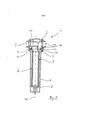
[054] A Figura 1 é uma vista de corte transversal de um filtro de ar de acordo com uma primeira modalidade preferencial da presente invenção;[054] Figure 1 is a cross-sectional view of an air filter according to a first preferred embodiment of the present invention;
[055] A Figura 2.1 é uma vista em perspectiva de uma parte su perior do elemento de filtro de acordo com uma primeira modalidade preferencial da presente invenção;[055] Figure 2.1 is a perspective view of a top part of the filter element according to a first preferred embodiment of the present invention;
[056] A Figura 2.2 é uma vista lateral da parte superior do filtro da Figura 2.1;[056] Figure 2.2 is a side view of the top of the filter in Figure 2.1;
[057] A Figura 2.3 é uma vista de topo da parte superior do filtro de acordo com as Figuras 2.1 e 2.2;[057] Figure 2.3 is a top view of the top of the filter according to Figures 2.1 and 2.2;
[058] A Figura 2.4 é uma vista de corte transversal de parte de um filtro de ar comprimido de acordo com a primeira modalidade preferencial da presente invenção antes de um movimento de fechamento da carcaça do filtro;[058] Figure 2.4 is a cross-sectional view of part of a compressed air filter according to the first preferred embodiment of the present invention before a closing movement of the filter housing;
[059] A Figura 2.5 é uma ilustração aumentada de um corte A da Figura 2.4;[059] Figure 2.5 is an enlarged illustration of section A of Figure 2.4;
[060] A Figura 2.6 é uma vista de corte transversal de parte de um filtro de ar comprimido de acordo com a primeira modalidade preferencial da presente invenção após um movimento de fechamento da carcaça do filtro;[060] Figure 2.6 is a cross-sectional view of part of a compressed air filter according to the first preferred embodiment of the present invention after a closing movement of the filter housing;
[061] A Figura 2.7 é uma ilustração aumentada do corte B da Fi gura 2.6;[061] Figure 2.7 is an enlarged illustration of section B of Figure 2.6;
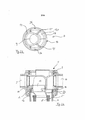
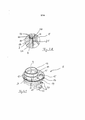
[062] A Figura 3.1 é uma vista em perspectiva de uma parte su perior de um elemento de uma carcaça de filtro de acordo com uma segunda modalidade preferencial da presente invenção;[062] Figure 3.1 is a perspective view of a top part of an element of a filter housing according to a second preferred embodiment of the present invention;
[063] A Figura 3.2 é uma vista lateral da parte superior do filtro da Figura 3.1;[063] Figure 3.2 is a side view of the top of the filter in Figure 3.1;
[064] A Figura 3.3 é uma vista de topo da parte superior do filtro de acordo com as Figuras 3.1 e 3.2;[064] Figure 3.3 is a top view of the top of the filter according to Figures 3.1 and 3.2;
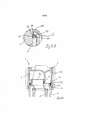
[065] A Figura 3.4 é uma vista de corte transversal de parte de um filtro de ar comprimido de acordo com a segunda modalidade preferencial da presente invenção antes de um movimento de fechamento da carcaça do filtro ou durante um movimento de fechamento da carcaça do filtro;[065] Figure 3.4 is a cross-sectional view of part of a compressed air filter according to the second preferred embodiment of the present invention before a closing movement of the filter housing or during a closing movement of the filter housing ;
[066] A Figura 3.5 é uma ilustração aumentada do corte C da Fi gura 3.4;[066] Figure 3.5 is an enlarged illustration of section C of Figure 3.4;
[067] A Figura 3.6 é uma ilustração aumentada do corte D da Fi gura 3.4;[067] Figure 3.6 is an enlarged illustration of section D of Figure 3.4;
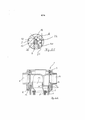
[068] A Figura 3.7 é uma vista de corte transversal de parte de um filtro de ar comprimido de acordo com a segunda modalidade da presente invenção após um movimento de fechamento da carcaça do filtro;[068] Figure 3.7 is a cross-sectional view of part of a compressed air filter according to the second embodiment of the present invention after a closing movement of the filter housing;
[069] A Figura 3.8 é uma ilustração aumentada do corte E da Fi gura 3.7;[069] Figure 3.8 is an enlarged illustration of section E of Figure 3.7;
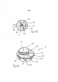
[070] A Figura 4.1 é uma vista em perspectiva de uma parte su perior de um elemento de filtro de acordo com uma terceira modalidade da presente invenção;[070] Figure 4.1 is a perspective view of a top part of a filter element according to a third embodiment of the present invention;
[071] A Figura 4.2 é uma vista lateral da parte superior do ele mento da Figura 4.1;[071] Figure 4.2 is a side view of the top of the element in Figure 4.1;
[072] A Figura 4.3 é uma vista de topo da parte superior do ele mento das Figuras 4.1 e 4.2;[072] Figure 4.3 is a top view of the top of the element of Figures 4.1 and 4.2;
[073] A Figura 4.4 é uma vista de corte transversal de parte de um filtro de ar comprimido de acordo com a terceira modalidade da presente invenção antes de um movimento de fechamento da carcaça do filtro;[073] Figure 4.4 is a cross-sectional view of part of a compressed air filter according to the third embodiment of the present invention before a closing movement of the filter housing;
[074] A Figura 4.5 é uma ilustração aumentada do corte F da Fi gura 4.4;[074] Figure 4.5 is an enlarged illustration of section F of Figure 4.4;
[075] A Figura 4.6 é uma vista de corte transversal de parte de um filtro de ar comprimido de acordo com a terceira modalidade da presente invenção após um movimento de fechamento da carcaça do filtro;[075] Figure 4.6 is a cross-sectional view of part of a compressed air filter according to the third embodiment of the present invention after a closing movement of the filter housing;
[076] A Figura 4.7 é uma ilustração aumentada do corte G da Fi gura 4.6;[076] Figure 4.7 is an enlarged illustration of section G of Figure 4.6;
[077] A Figura 5.1 é uma vista de corte transversal de parte de um filtro de ar comprimido de acordo com uma quarta modalidade da presente invenção;[077] Figure 5.1 is a cross-sectional view of part of a compressed air filter according to a fourth embodiment of the present invention;
[078] A Figura 5.2 é uma ilustração aumentada da do corte H da Figura 5.1 antes de o elemento de vedação ser sujeito a pressão; e[078] Figure 5.2 is an enlarged illustration of section H of Figure 5.1 before the sealing element is subjected to pressure; and
[079] A Figura 5.3 é uma ilustração aumentada do corte I da Fi gura 5.1 após o elemento de vedação ser sujeito a pressão.[079] Figure 5.3 is an enlarged illustration of section I of Figure 5.1 after the sealing element is subjected to pressure.
[080] Nas figuras os mesmos numerais de referência indicam componentes de funcionalidade idêntica a menos que indicado em contrário.[080] In the figures the same reference numerals indicate components of identical functionality unless otherwise indicated.
[081] A Figura 1 é uma ilustração esquemática de corte transver sal de um filtro de ar comprimido 1 de acordo com uma modalidade preferencial da presente invenção. Como pode ser visto na Figura 1, o filtro de ar comprimido 1 tem uma carcaça de filtro multi-peças 2 que compreende uma parte superior da carcaça 3 e uma tampa da carcaça 4 que pode ser conectada com segurança a essa. A parte superior da carcaça 3 tem um canal de entrada e descarga 9 e um canal de entrada e descarga 10 e conexões correspondentes para o ar comprimido que se pretende que seja limpo ou tenha sido limpo.[081] Figure 1 is a schematic cross-sectional illustration of a
[082] O filtro de ar comprimido1 compreende adicionalmente um elemento de filtro 5 que pode ser introduzido dentro da carcaça do filtro 2 e que compreende um aparte inferior do elemento 6, uma parte superior do elemento 7 e um meio filtrante 8 e, de acordo com a presente modalidade, é preferencialmente construído de uma maneira simétrica rotacionalmente relativa ao eixo geométrico central 46 do mesmo com a exceção da parte de gargalo 13 e nervuras 15. De acordo com a Figura 1, por exemplo, o meio filtrante é enrolado ou plissado na forma de um cilindro oco e é conectado de modo vedante com a parte superior do elemento 7 e a parte inferior do elemento 6 do elemento de filtro 5 colado, por exemplo seguramente ou de forma separável e de uma forma adequada vedante. Alternativamente, o meio filtrante 8 também pode compreender um enchimento de um meio filtrante granular, tal como, por exemplo, carvão ativado em uma construção de transporte, ou um corpo oco poroso.[082] The compressed air filter1 additionally comprises a
[083] De acordo com a presente modalidade, o elemento de filtro 5 pode adicionalmente ser conectado seguramente à tampa da carcaça 4, com tal conexão sendo acarretada, por exemplo, por meio de uma conexão com rosca 11 de acordo com esta modalidade, como pode ser visto na Figura 1.[083] According to the present embodiment, the
[084] A tampa da carcaça 4 pode adicionalmente ser conectada seguramente em vedação com a parte superior da carcaça 3 em uma posição fechada por meio de uma conexão rotativa 12. No estado ajustado ou na posição fechada, o elemento de filtro 5 na carcaça de filtro 2 separa o lado de entrada do lado de descarga de tal maneira que o ar comprimido a ser filtrado tem que fluir através do meio filtrante 8. Para este fim, a parte superior do elemento 7 é introduzida em vedação dentro da carcaça do filtro 2 de modo que o espaço interno do meio filtrante 8 disposto cilindricamente oco é conectado ao lado de entrada ou descarga 9 e o espaço externo do meio filtrante 8 disposto cilindricamente oco é conectado ao lado de descarga ou entrada 10 da parte superior da carcaça 3. Na modalidade ilustrada na Figura 1, o ar comprimido flui na posição fechada do filtro de ar comprimido 1 através do canal de entrada 9 e parte de gargalo 13 da parte superior do elemento 7 para dentro do interior do meio filtrante 8, através da paredecilíndrica do meio filtrante 8 para separar corpos estranhos do fluxo de ar comprimido através do canal de fluxo que é formado entre a parede externa do meio filtrante 8 e parede interna da carcaça do filtro 4 e o canal de fluxo que é formado entre a parte de gargalo 13 e uma parte de colar 14 associada da parte superior do elemento 7 do elemento de filtro 5 para o canal de descarga 10 da parte superior da carcaça 3. Sob algumas circunstâncias, pode ser vantajoso fornecer a direção do fluxo de ar comprimido para ser inversa ao caminho de fluxo acima.[084] The cover of the
[085] A Figuras 2.1, 2.2 e 2.3 são várias vistas de uma parte su perior do elemento 7 do elemento de filtro 5 de acordo com uma primeira modalidade preferencial da presente invenção e Figuras 2.4 a 2.7 são vistas de corte transversais de parte de um filtro de ar comprimido 1 de acordo com a primeira modalidade preferencial da presente invenção antes e depois de um movimento de fechamento da carcaça do filtro 2.[085] Figures 2.1, 2.2 and 2.3 are several views of an upper part of the
[086] De acordo com a primeira modalidade, a parte superior do elemento 7 tem uma parte de gargalo 13 que já foi mencionada acima e que tem uma forma de seção transversal que difere da forma circular, por exemplo, uma forma similar a uma forma triangular muito arredondada. A parte de gargalo 13 é adicionalmente posicionada excentricamente relativa ao eixo geométrico central 46 do elemento do filtro 7 projetando para frente na direção da parte superior da carcaça 3 associada e é conectada à parte de colar 14 que se estende em torno da parte do gargalo 13 por meio de uma pluralidade de nervuras 15. As nervuras 15 se estendem substancialmente em uma direção radial e simultaneamente axial e preferencialmente tem uma construção que é otimizada em termos técnicos de fluxo a fim de reduzir a diferença de pressão. Por exemplo, nervuras individuais 15 são construídas por isso para ter curvatura especial. As nervuras 15 permitem que o ar comprimido flua em uma direção longitudinal do elemento de filtro 5 entre a parte de gargalo 13 e a parte de colar 14 da parte superior do elemento 7. A parte de colar 14 é, de acordo com a primeira modalidade ilustrada,construída para ser rotacionalmente simétrica relativa ao eixo geométrico central 46 do elemento de filtro 5 e para se estender em torno de toda a periferia da parte de gargalo 13. A parte de colar 15 preferencialmente tem um diâmetro externo que corresponde substan- cialmente ao diâmetro externo do lado frontal associado da tampa da carcaça 4.[086] According to the first embodiment, the upper part of the
[087] A parte do gargalo 13 e/ou o contorno de recepção associ ado do mesmo na parte superior da carcaça 3 compreende adicionalmente uma vedação 44 que é recebida em uma canaleta associada 45 e que atua como uma conexão impermeável a fluido entre a parte de gargalo 13 e o canal de entrada ou descarga correspondente 9 na parte superior da carcaça 3.[087] The
[088] A parte de colar 14 compreende uma face de contato 16 direcionada para o lado externo na região voltada para a parte do gargalo 13. A face de contato 16 serve para receber um anel de vedação 22 e é construída para ser substancialmente simétrica rotacionalmente relativa ao eixo geométrico central 46 do elemento de filtro 5 e para se estender em torno deste. O diâmetro da face de contato 16 afunila de uma maneira predeterminada em direção a parte inferior do elemento 6. Por exemplo, a face de contato 16 é na forma de uma face de cone cujo eixo geométrico central coincide com o eixo geométrico central 46 do elemento de filtro 5. A ponta imaginária do cone é dirigida na direção da parte inferior do elemento 6 e compreende um passo na amplitude entre 1:2 e 2:1, ou seja, um ângulo de passo α entre a face de contato 16 e o eixo geométrico central 46 do elemento de filtro 5 preferencialmente entre aproximadamente 25° e 65°. Entretanto, a face de contato 16 pode ter um passo que muda constantemente ou em partes específicas.[088] The
[089] A face de contato é delimitada na direção da parte do gar galo 13 por uma nervura de delimitação 17 que também é preferenci-almenteperiférica e que é rotacionalmente simétrica relativa ao eixo geométrico central 46 do elemento de filtro 5. Na direção da parte inferior do elemento 6, a face de contato 16 é delimitada por um canal periférico 18 que é rotacionalmente simétrico relativo ao eixo geométrico central 46 do elemento de filtro 5 e que se funde na direção da parte inferior do elemento 6 dentro de uma parte de guia substancialmente cilíndrica 19 da parte de colar 14, com a qual a parte de colar 14 é recebida e centralizada na tampa da carcaça 4.[089] The contact face is bounded towards the
[090] Como pode ser visto, por exemplo, na Figura 2.2 a parte de colar 14 tem adicionalmente na parte de guia cilíndrica 19 uma rosca externa 20 que pode ser movida em engate roscado com uma rosca interna correspondente 21 da tampa da carcaça 4. O elemento de filtro 5 pode ser atarraxado seguramente dentro de uma tampa da carcaça 4 por meio daquela conexão roscada 11.[090] As can be seen, for example, in Figure 2.2 the
[091] Um anel de vedação 22 também é fornecido e é preferenci almenteconstruído como um anel de vedação convencional com uma seção transversal substancialmente circular do cordão de vedação. O anel de vedação 22 é puxado para a face de contato 16 preferencialmente com uma leve pré-tensão radial em uma posição de retenção predeterminada. O diâmetro externo do anel de vedação 22 é, naquela posição de retenção, na parte de colar 14 ou face de contato 16, menor ou igual ao diâmetro da face periférica interna 23 da parte superior da carcaça 3 e cujo anel de vedação 22 junta em vedação no estado montado na posição fechada. Adicionalmente a face periférica interna 23 da parte superior da carcaça 3 atuando como a primeira face de vedação, a face de extremidade da tampa da carcaça 4 forma a segunda face de vedação 24 da carcaça do filtro 2, de encontro a qual o anel de vedação 22 é movido em contato resiliente por um movimento de fechamento da carcaça do filtro 2 e consequentemente na posição fechada de acordo com um princípio operacional que é descrito abaixo em maior detalhe.[091] A
[092] A fim de manter o pré-tensionamento resiliente permanen temente do anel de vedação 22, a face de contato 16 na parte do coar 14 pode ser construída para ser resiliente, por exemplo, na forma de segmentos individuais, divididos radialmente e flexivelmente resilientes.[092] In order to permanently maintain the resilient pre-tensioning of the sealing
[093] A ação de vedação da carcaça do filtro 2 é explicada abai xo em maior detalhe com referência as Figuras 2.4 a 2.7, as Figuras 2.4 e 2.5 ilustram um estado antes do movimento de fechamento da carcaça do filtro 2 e as Figuras 2.6 e 2.7 ilustram um estado após o movimento de fechamento da carcaça do filtro 2.[093] The sealing action of the
[094] A fim de receber a parte de gargalo 13 da parte superior do elemento 7, a parte superior da carcaça 3 tem um contorno de recepção correspondente 25, em que a parte de gargalo 13 é capaz de ser introduzida no contorno de recepção 25 a fim de fornecer meios de prevenção à rotação para o elemento de filtro 5 em torno do eixo longitudinal do mesmo relativo à parte superior da carcaça 3. É óbvio para um indivíduo versado na técnica que um meio de prevenção de rotação desejado também é possível devido à seção transversal da parte do gargalo 13 ser construída para ser diferente da forma circular e com uma disposição central do mesmo ao mesmo tempo.[094] In order to receive the
[095] De acordo com a presente primeira modalidade, a conexão rotativa 12 entre a tampa da carcaça 4 e a parte superior da carcaça 3 é na forma de uma conexão tipo baioneta de modo que a montagem da tampa da carcaça 4 na parte superior da carcaça 3 é associada com um movimento rotacional da tampa da carcaça 4 em torno do eixo longitudinal do mesmo relativo à parte superior da carcaça 3. Entretanto, a conexão rotativa 12 também pode ser construída por meio de uma conexão roscada adequada ou algo semelhante.[095] According to the present first embodiment, the
[096] Na primeira modalidade, uma conexão tipo baioneta sem qualquer passo é usada preferencialmente de tal maneira que a rotação de fechamento entre a tampa da carcaça 4 e a parte superior da carcaça 3 seja executada sem qualquer movimento axial relativo entre aqueles dois componentes.[096] In the first mode, a bayonet-type connection without any step is preferably used in such a way that the closing rotation between the cover of the
[097] A fim de introduzir o elemento de filtro 5 na carcaça do filtro 2, o elemento de filtro 5 é primeiro atarraxado na tampa da carcaça 4 por meio da conexão roscada 11 ou da rosca interna 21 e da rosca externa 20 até o anel de vedação 22 juntar fracamente com a segunda face de vedação 24 ou a correspondente face de extremidade da tampa da carcaça 4. Neste estado, o anel de vedação 22 é pré-tensionado apenas levemente e ainda não é expandido ao longo da face de contato 16, como ilustrado na Figura 2.5. A fim de indicar para o usuário uma posição angular do elemento de filtro 5 necessária para a montagem relativa da tampa da carcaça 4, marcações óticas adequadas 26 são fornecidas preferencialmente neste caso na parte superior do elemento 7 e/ou na tampa da carcaça 4. Alternativa ou adicionalmente, a posição angular relativa também pode ser indicada para o usuário como marcações táteis por projeções de engate resilientes, por exemplo, na parte de colar 14 e por contra-contornos correspondentes na tampa da carcaça 4.[097] In order to introduce the
[098] Devido à orientação relativa correspondente da rosca inter na 21 na parede interna da carcaça da tampa da carcaça 4 e a rosca externa 20 na parte de colar 14 da parte superior do elemento 7, a parte do gargalo posicionada e construída especialmente 13 e a conexão tipo baioneta 12 entre a parte superior da carcaça 3 e a tampa roscada 4, é garantido que a parte do gargalo 13 do elemento de filtro 5 em uma posição angular predeterminada pode ser introduzido de uma maneira segura rotacionalmente em uma direção axial para dentro do contorno de recepção correspondente 25 na parte superior da carcaça 3 e, consequentemente, a tampa da carcaça 4 pode ser introduzida na parte superior da carcaça 3 com o elemento de filtro 5 atarraxado a tampa da carcaça 4 e movida em engate com a parte superior da carcaça 3 por meio da conexão tipo baioneta 12. Durante um movimento de fechamento da carcaça do filtro 2, ou seja, quando a tampa da car- caça 4 é girada relativa à parte superior da carcaça 3, a posição angular do elemento de filtro 5 relativa à parte superior da carcaça 3 é mantida devido ao meio de prevenção de rotação descrito acima, mas com rotação relativa deste modo sendo produzida entre o elemento de filtro 5 e a tampa da carcaça 4 de tal maneira que o elemento de filtro 5 seja movido para dentro da tampa da carcaça 4. O passo da conexão roscada 11, ou seja, o passo da rosca externa 20 e da rosca interna 21, determina a magnitude do movimento relativo entre o elemento de filtro 5 e a tampa da carcaça 4 a um ângulo predeterminado de rotação da tampa da carcaça 4 relativo à parte superior da carcaça 3.[098] Due to the corresponding relative orientation of the
[099] Consequentemente, a parte de colar 14 do elemento de fil tro 5 é atarraxada adicionalmente dentro da tampa 4 durante o movimento de fechamento da carcaça do filtro 2, ou seja, é produzido movimento adicional relativo entre os dois e direcionados um para o outro, de tal maneira que a segunda face de vedação 24 ou o lado terminal da tampa da carcaça 4 impulsiona o anel de vedação 22 para cima junto com a face de contato 16 e acarreta a expansão do anel de vedação 22 sobre a face de contato 16 que é construída adequadamente de uma maneira inclinada, como ilustrado em particular nas Figuras 2.5 e 2.7. A nervura de delimitação 17 serve para delimitar a expansão do anel de vedação 22 e consequentemente garantir expansão predeterminada e definida do anel de vedação 22.[099] Consequently, the
[0100] Devido a esta expansão radial do anel de vedação 22, o anel 22 também é movido em contato vedante com a primeira face de vedação 23, ou seja, a face periférica interna da parte superior da carcaça 3, como ilustrado na Figura 2,7, durante o movimento de fechamento da carcaça de filtro 2 adicionalmente ao contato com a segunda face de vedação 24. Consequentemente, o anel de vedação 22 faz contato com a primeira face de vedação 23 apenas no final do movimento de fechamento da carcaça do filtro, o que é vantajoso por ra- zões da tecnologia de atrito.[0100] Due to this radial expansion of the sealing
[0101] Deve ser observado neste ponto que a expansão radial do anel de vedação 22 também pode ser acarretada de uma maneira equivalente pelo fato de que, em vez de o anel de vedação 22 ser guiado juntamente com a face de vedação 16, o anel de vedação 22 é expandido radialmente pelo anel de vedação ser correspondentemente apertado apenas por meio de uma operação de compressão devido ao contato correspondente com a face de contato 16 construída correspondentemente e sendo sujeita a expansão radial devido àquela ação de aperto. Neste caso, por exemplo, a face de contato 16 pode ser na forma de uma face de contato em ângulo reto na forma de L ou algo semelhante, quando uma força atua axialmente no anel de vedação 22, compressão do anel de vedação 22 de tal maneira que o mesmo é sujeito a expansão radial.[0101] It should be noted at this point that radial expansion of the
[0102] Finalmente, o contato de encontro às duas faces de veda ção 23 e 24 com um acúmulo de pressão na carcaça do filtro 2 sendo aumentado devido à força de pressão da pressão interna no anel de vedação 22 de modo que a vedação completa e segura desejada da carcaça do filtro 2 é garantida.[0102] Finally, the contact against the two sealing faces 23 and 24 with a build-up of pressure in the
[0103] De acordo com a primeira modalidade, o elemento de filtro 5 é suportado axialmente na tampa da carcaça 4 por meio da conexão roscada 11 de tal maneira que, embora o anel de vedação 22 seja pré- tensionado de forma resiliente no estado montado no qual o elemento de filtro 5 é introduzido na tampa da carcaça 4, o mesmo não é localizado no caminho da força principal entre a parte superior da carcaça 3 e a tampa da carcaça 4. Deste modo a vida útil do anel de vedação 22 é vantajosamente aumentada.[0103] According to the first embodiment, the
[0104] A desmontagem do filtro de ar comprimido 1 para mudar um elemento de filtro 5 que pode estar contaminado é executada de maneira similar a sequência de montagem descrita acima, mas na or- dem inversa.[0104] The disassembly of the
[0105] É óbvio para um indivíduo versado na técnica que as di mensões e formas geométricas dos componentes e faces individuais, em particular as faces de vedação, o anel de vedação, a face de contato e a nervura de delimitação, podem ser modificadas uma vez que o anel de vedação é expandido radialmente durante o movimento de fechamento da carcaça do filtro ao longo da face de contato para vedar o contato entre as faces de vedação. Também deve ser observado neste ponto que, no presente pedido, o termo “face de contato afunilada” deve ser entendido como sendo qualquer tipo de face de contato 16 que defina o espaço de recepção para receber o anel de vedação 22 de tal maneira que a força atuando axialmente no anel de vedação 22 acarrete expansão radial do anel de vedação. Consequentemente, por exemplo, uma face de contato em forma de L ou uma face de contato com um ângulo agudo entre as duas partes da face de contato também deve ser entendida e deve ser considerada como sendo equivalente a face de contato 16 ilustrada nas figuras de acordo com o presente pedido.[0105] It is obvious to a person skilled in the art that the dimensions and geometric shapes of the individual components and faces, in particular the sealing faces, the sealing ring, the contact face and the boundary rib, can be modified in an since the gasket is radially expanded during the closing movement of the filter housing along the contact face to seal the contact between the sealing faces. It should also be noted at this point that, in the present application, the term "tapered contact face" is to be understood as any type of
[0106] Um filtro de ar comprimido 1 e um elemento de filtro 5 de acordo com uma segunda modalidade preferencial da presente invenção são explicados em maiores detalhes abaixo com referência as Figuras 3.1 e 3.8 respectivamente. A segunda modalidade da presente invenção tem, ao contrário da primeira modalidade, uma conexão roscada modificada 11 entre o elemento de filtro 5 e a tampa da carcaça 4 que é avaliada em maiores detalhes abaixo.[0106] A
[0107] De acordo com a segunda modalidade preferencial, a parte de guia cilíndrica 19 da parte de colar 14 não tem uma rosca externa, mas em vez disso uma pluralidade de linguetas resilientes deformáveis resilientemente 27. As linguetas resilientes flexíveis 27 são dispostas ao longo da face periférica da parte de guia 19 preferencialmente com espaçamento regular uma da outra, como pode ser visto particularmente na Figura 3.2, em um nível axial diferente de modo que é assegurado um engate roscado predeterminado com uma rosca interna associada 21 da tampa da carcaça 4.[0107] According to the second preferred embodiment, the
[0108] As linguetas resilientes 27 são, por exemplo, na forma de abas que são ejetadas da parte de guia 19 e a extremidade livre das quais é orientada axialmente na direção da parte do gargalo 13. As linguetas resilientes 27 se estendem radialmente com as extremidades livres das mesmas antes do elemento de filtro 5 ser introduzida dentro da tampa da carcaça 4 preferencialmente substancialmente até o centro da seção de corte transversal do cordão de vedação, como ilustrado na Figura 3.5, e no máximo substancialmente até o diâmetro externo do anel de vedação 22. As linguetas resilientes 27 deste modo formam um dispositivo de suporte para conduzir o anel de vedação 22 antes de o elemento de filtro 5 ser introduzido dentro da tampa da carcaça 4 em uma posição predeterminada. Entretanto, também é concebível para cada uma das linguetas resilientes 27 ter braços que se estendem em uma direção substancialmente radial na qual servem para suportar os anéis de vedação 22. Neste caso, as linguetas resilientes 27 também podem se estender radialmente além da extensão radial do anel de vedação 22. Por exemplo, os braços são formados na extremidade livre das linguetas resilientes 27 e são construídos de uma maneira que podem ser deslocados para dentro das aberturas ejetadas se as linguetas resilientes são deformadas adequadamente.[0108] The
[0109] As linguetas resilientes 27 são adicionalmente pré- tensionadas em direção ao lado externo a podem ser ajustadas de forma resiliente na direção do eixo geométrico central 46 do elemento de filtro 5 devido à propriedade resiliente das mesmas, como ilustrado na Figura 3.6.[0109] The
[0110] A tampa da carcaça tem preferencialmente uma rosca que tem um perfil semelhante a dente de serra como rosca interna 21 que corresponde as linguetas resilientes 27 na face de periferia interna da mesma, como ilustrado nas Figuras 3.5 e 3.6. Neste caso, as paredes de rosca individuais da rosca interna 21 podem ter diferentes profundidades de rosca. Por exemplo, a profundidade da rosca pode se estender axialmente na direção da segunda face de vedação 24 da tampa de vedação 4. Uma segunda face de vedação 24 que é tão ampla quanto possível deste modo fornecida por uma espessura de parede predeterminada da tampa da carcaça 4 de modo que é garantido um contato otimizado de encontro ao anel de vedação associado 22. Devido à profundidade se estender adequadamente, também é possível para o elemento de filtro 5 ser capaz de ser vantajosamente desenros- cado da tampa da carcaça 4 com o menor número possível de rotações.[0110] The housing cover preferably has a thread that has a sawtooth-like profile as an
[0111] De acordo com a segunda modalidade preferencial, o ele mento de filtro 5 pode ser introduzido dentro da tampa da carcaça 4 quando o anel de vedação 22 é retido em uma posição de retenção predeterminada nas extremidades livres das linguetas resilientes 27. Neste caso, as linguetas resilientes 27 se movem em engate de encaixerápido com a rosca interna semelhante a dentes de serra 21 da tampa da carcaça 4 a partir de uma profundidade de inserção predeterminada devido à construção resiliente da mesma. O elemento de filtro 4 pode ser enroscado adicionalmente a fim de introduzir o elemento de filtro 5 adicionalmente dentro da tampa da carcaça 4 devido às linguetas resilientes 27 e o perfil de dente de serra da rosca interna 21 constituírem um tipo de engate roscado e permitirem a rotação da rosca. A desmontagem do elemento de filtro 5 é executada de maneira similar através do desenroscamento da tampa da carcaça 4 da rosca interna 21 na direção oposta.[0111] According to the second preferred embodiment, the
[0112] De maneira similar a primeira modalidade preferencial, in- troduzir ou enroscar o elemento de filtro 5 dentro da tampa da carcaça 4 de acordo com a segunda modalidade também produz inserção adicional do elemento de filtro 5 dentro da tampa da carcaça 4 de tal maneira que a segunda face de vedação 24 expande radialmente o anel de vedação 22 ao longo da face de contato 16, como ilustrado na Figura 3.6, e o impele em contato vedante com a primeira face de vedação da parte superior da carcaça 3 (não ilustrada).[0112] Similarly to the first preferred embodiment, inserting or screwing the
[0113] Com respeito às características e operações da presente invenção que não tem sido explicadas em maiores detalhes em conjunto com a descrição acima da segunda modalidade preferencial, pode ser feita referência a descrição prévia da primeira modalidade devido a estas características e operações serem de forma similar de modo que é possível dispensar uma explicação detalhada das mesmas a fim de evitar repetição desnecessária.[0113] With respect to the features and operations of the present invention that have not been explained in greater detail in conjunction with the above description of the second preferred modality, reference may be made to the previous description of the first modality due to these features and operations being so similar so that it is possible to dispense with a detailed explanation of them in order to avoid unnecessary repetition.
[0114] Um filtro de ar comprimido 1 e um elemento de filtro 5 de acordo com uma terceira modalidade da presente invenção são explicados em maiores detalhes abaixo com referência as Figuras 4.1 a 4.7, respectivamente.[0114] A
[0115] De acordo com a terceira modalidade preferencial, em comparação com as duas modalidades mencionadas acima, um movimento relativo entre a parte de colar 14 do elemento de filtro 5 e a tampa da carcaça 4 é acarretado de uma maneira diferente durante o movimento de fechamento da carcaça de filtro 2. De acordo com a terceira modalidade, a conexão rotativa 12 entre a parte superior da carcaça 3 a tampa da carcaça 4 é construída como uma conexão do tipo baioneta que tem um passo predeterminado de modo que a parte superior da carcaça 3 a tampa da carcaça 4 executam movimento axial relativo uma em direção a outra durante o movimento de fechamento da carcaça do filtro 2.[0115] According to the third preferred embodiment, compared to the two aforementioned embodiments, a relative movement between the
[0116] Também é fornecido um dispositivo de batente que produz uma parada axial entre a parte de colar 14 da parte superior do elemento de filtro 7 e a parte superior da carcaça 3 a fim de mover axialmente a parte superior do elemento de filtro 7 e consequentemente a face de contato 16 da parte de colar 14 relativa à tampa da carcaça 4 durante um movimento de fechamento da carcaça do filtro 2. O dispositivo de batente 28 compreende preferencialmente a uma face de batente da parte da extremidade frontal da parte de colar 14 voltada para a parte superior da carcaça 3 e uma parte de batente associada cor-respondentemente da parte superior da carcaça 3 voltada para a parte de colar 14, como ilustrado, por exemplo, nas Figuras 4.5 e 4.7. Consequentemente, o dispositivo de batente 28 acarreta uma parada entre a face de batente da parte de colar 14 do elemento de filtro 5 e a parte de batente associada correspondente da parte superior da carcaça 3, durante o movimento de fechamento da carcaça do filtro 2 e o movimento axial relativo associado entre a parte superior da carcaça 3 e a tampa da carcaça 4, de tal maneira que o movimento axial relativo de um em direção ao outro é acarretado entre o elemento de filtro 5 e a tampa da carcaça 4. Este movimento relativo impulsiona o anel de vedação 22 ao longo da face de contato 16 e consequentemente expande radialmente o anel de vedação 22 em contato vedante com a primeira face de vedação associada 23 em um estado pré-tensionado resiliente, de maneira semelhante às modalidades já explicadas acima.[0116] A stop device is also provided that produces an axial stop between the
[0117] Diferente das duas modalidades mencionadas anteriormen te, entretanto, de acordo com a terceira modalidade preferencial uma conexão entre o elemento de filtro 5 e a tampa da carcaça 4 não é produzido por meio de uma conexão roscada correspondente, mas em vez disso por meio de uma conexão de engate 29 construída adequadamente que é explicada em maiores detalhes abaixo.[0117] Unlike the two aforementioned embodiments, however, according to the third preferred embodiment a connection between the
[0118] Como pode ser visto em particular nas Figuras 4.1 e 4.2, a parte superior do elemento 7 tem, por exemplo, dois dispositivos de engate na forma de prendedores 30 que são preferencialmente na forma de projeções da parte de colar 14 na direção da parte inferior do elemento 6 e construídos para serem deslocados perifericamente por aproximadamente 180°, cujas projeções são resilientes em uma direção radial. Por exemplo, os prendedores 30 formam cada um uma projeção na direção da parte inferior do elemento 6 de uma nervura associada 15. Os prendedores 30 adicionalmente têm preferencialmente uma construção substancialmente retangular com bordas laterais arredondadas. Cada prendedor 30 tem adicionalmente uma abertura substancialmente central ou região de recepção 31 para receber um dispositivo de contra-engate 35 associado correspondentemente. Para uma operação de engate mais simples, cada prendedor 30 compreende adicionalmente bordas laterais externas chanfradas 32 e pelo menos uma borda inferior externa chanfrada 33. As partes chanfradas que suportam adequadamente uma operação de desengate lateral do dispositivo de contra engate associado 35 são providas adicionalmente pelo menos nas bordas laterais 34 da abertura 31.[0118] As can be seen in particular in Figures 4.1 and 4.2, the upper part of the
[0119] A tampa da carcaça 4 preferencialmente tem adequada mente, como o dispositivo de contra-engate 35, projeções de engate correspondentes 35 que são dispostas na face periférica interna e que desliza sobre as bordas chanfradas dos prendedores 30 ou abertura 31 dos prendedores 31 durante os movimentos correspondentes de engate e desengate e pode consequentemente ser engatado em uma conexão de engate correspondente com os prendedores 30 ou desengatado de uma conexão de engate. As projeções de engate 35 são construídas em uma maneira complementar para engate posicional- mente estável com as aberturas 31 associadas dos prendedores 30 de modo que o elemento de filtro 5 seja engatado com a tampa da carcaça 4 em uma maneira posicionalmente estável no estado engatado.[0119] The cover of the
[0120] As bordas laterais externas 32 dos prendedores 30 prefe- rencialmente têm chanfros relativamente planos em relação a chanfros relativamente íngremes das bordas laterais 34 da abertura 31. Consequentemente, a aplicação de força para engate entre o prendedor 30 e a projeção de engate associada 35 é menor para o usuário do que a aplicação de força para a operação de desengate correspondente. Portanto é vantajosamente possível garantir para o usuário uma posi-ção angular tátil preferencial do elemento de filtro 5 relativa à tampa da carcaça 4. Aquela posição angular preferencial é preferencialmente selecionada de tal maneira que a parte do gargalo 13 do elemento de filtro 5 que tem um contorno de recepção associado correspondentemente 25 possa ser introduzido ali para evitar rotação na parte superior da carcaça 3 e a conexão tipo baioneta 12 entre a tampa da carcaça 4 e a parte superior da carcaça 3 possa ser movida axialmente em engate, ou seja, o posicionamento dos prendedores 30 e das projeções de engate 35 associadas correspondentemente é selecionada preferencialmente de modo que, durante o estado de engate, a conexão tipo baioneta entre a tampa da carcaça 4 e a parte superior da carcaça 3 fique na posição aberta para separar estes componentes um do outro. Consequentemente, o elemento de filtro 5 é vantajosamente mantido axialmente na tampa da carcaça 4 quando a tampa da carcaça 4 é separada da parte superior da carcaça 3 através da conexão de engate acarretada entre os prendedores 30 a projeções de engate associadas 35.[0120] The outer side edges 32 of the
[0121] A fim de introduzir um novo elemento de filtro 5, o elemento de filtro 5 é primeiro introduzido axialmente na tampa da carcaça 4, ou já na posição de engate correspondente ou em uma posição de desengate, em que a posição de engate é acarretada naquele caso por rotação manual subsequente do elemento de filtro 5. A operação de engate pode neste caso atuar como uma indicação tátil de uma posição angular preferencial para o usuário. Entretanto, também é possível conceber marcações alternativas ou adicionais 26 adequadas para estepropósito.[0121] In order to introduce a
[0122] A tampa da carcaça 4 com o elemento de filtro 5 engatado é subsequentemente introduzida na parte superior da carcaça 3 adequada ou seguramente conectada à ela em uma maneira de vedação devido ao movimento de fechamento por meio da conexão tipo baioneta 12. Para a operação de introdução, é novamente possível fornecer marcações predeterminadas a fim de indicar uma posição angular preferencial para o usuário. Como já explicado em detalhes acima, o movimento relativo entre o elemento de filtro 5 e a tampa da carcaça 4 é produzido deste modo pelo dispositivo de parada axial 28, por meio do qual o anel de expansão 22 é expandido radialmente ao longo da face de contato 16 e em contato vedante com a primeira face de vedação 23.[0122] The cover of the
[0123] A operação é executada na ordem inversa a fim de remover um elemento de filtro 5 que está, por exemplo, contaminado, o elemento de filtro 4 ainda está conectado engatado à tampa da carcaça 4 após a tampa da carcaça 4 ter sido removida da parte superior da carcaça 3 através da conexão tipo baioneta 12 sendo desprendida. Através da rotação manual do elemento de filtro 5 na tampa da carcaça 4, a conexão de engate pode ser desengatada e o elemento de filtro 5 pode ser facilmente removido da tampa da carcaça 4.[0123] The operation is performed in reverse order in order to remove a
[0124] Os prendedores 30 são adicionalmente construídos prefe rencialmente de tal maneira que os mesmos tomem um estado não deformado radialmente tanto na posição de engate nas projeções de engate associadas correspondentemente 35 e na posição desengatada remota as projeções de engate 35. Uma vez que as partes superiores do elemento 7 são geralmente produzidas como componentes moldados por injeção de um material plástico adequado que pode exibirocorrências de deslizamento em algumas circunstâncias sob de- formações ou pré-tensões extremas permanentes, aquele estado não deformado radialmente dos prendedores 30 garante uma vida útil mais longa do mesmo e consequentemente da conexão de engate entre o elemento de filtro 5 e a tampa da carcaça 4. Entretanto, é óbvio para uma pessoa versada na técnica que uma cinemática inversa da conexão de engate explicada acima também é concebível com modificações adequadas, de acordo com a qual as projeções de engate ou dispositivos de contra engate similares sejam providos adequadamente, por exemplo, no elemento de filtro 5 e os prendedores 30 associados ou dispositivos complementares de engate que são construídos de forma diferente de uma maneira correspondente sejam providos adequadamente em uma face periférica interna da tampa da carcaça 4.[0124] The
[0125] Deve ser observado neste ponto que os prendedores tam bém podem ter uma pluralidade de aberturas em que cada uma tem bordas chanfradas correspondentes, por exemplo, duas aberturas idênticas por prendedor dispostas uma ao lado da outra. Os prendedores podem adicionalmente ter cada um uma região de abertura lateral de modo que uma rampa deslizante seja fornecida em apenas um lado predeterminado e o dispositivo de contra-engate associado seja introduzido ou retirado no lado oposto sem qualquer rampa deslizante na região de recepção do respectivo prendedor. Entende-se que isto seja fornecido e adaptado de acordo com a construção dos outros componentes e a direção da rotação durante o movimento de fechamento. Se os prendedores ou um engate ou dispositivo de contra-engate corres-pondenteé/são fornecidos, é possível adicionalmente dispensar dispositivos adicionais para indicar a posição angular porque a conexão de engate descrita acima pode assumir esta função.[0125] It should be noted at this point that the fasteners can also have a plurality of openings each having corresponding beveled edges, for example two identical openings per fastener arranged side by side. The fasteners may additionally each have a side opening region so that a sliding ramp is provided on only one predetermined side and the associated counter-engagement device is inserted or withdrawn on the opposite side without any sliding ramp in the respective receiving region. fastener. It is understood that this is provided and adapted according to the construction of the other components and the direction of rotation during the closing movement. If fasteners or a corresponding coupling or counter-engaging device is/are provided, it is additionally possible to dispense with additional devices to indicate the angular position because the coupling connection described above can assume this function.
[0126] Com respeito às características e operações da presente invenção que não foram explicadas em maiores detalhes a respeito da descrição da terceira modalidade acima, podem ser feitas referências as descrições da primeira e segunda modalidades acima devido a estas características e operações serem de forma similar de modo que uma explicação detalhada das mesmas pode ser dispensada para evitar uma repetição desnecessária. Deve ser observado adicionalmente neste ponto que soluções especiais individuais das primeiras três modalidades mencionadas podem ser combinadas livremente umas com as outras dentro do escopo da noção inventiva geral da presente invenção desde que a mesma pareça vantajosa tecnicamente para um indivíduo versado na técnica.[0126] With respect to the features and operations of the present invention that have not been explained in greater detail regarding the description of the third embodiment above, references may be made to the descriptions of the first and second embodiments above because these features and operations are similar in form so that a detailed explanation of them can be dispensed with to avoid unnecessary repetition. It should additionally be noted at this point that individual special solutions of the first three mentioned embodiments can be freely combined with each other within the scope of the general inventive notion of the present invention as long as it appears technically advantageous to a person skilled in the art.
[0127] Um filtro de ar comprimido 1 e um elemento de filtro 5 de acordo com uma quarta modalidade preferencial da presente invenção são explicados abaixo em maiores detalhes com referências as Figuras 5.1 a 5.3. Com respeito a explicações gerais, podem ser feitas referências às modalidades descritas acima para evitar repetição.[0127] A
[0128] De acordo com a quarta modalidade preferencial, a parte de colar 14 da parte superior do elemento 7 tem uma construção periférica, por exemplo, que é rotativamente simétrica relativa ao eixo geométrico central 46 do elemento de filtro 5 e que tem uma geometria semelhante a S que é angulada duas vezes, como pode ser visto em particular nas Figuras 5.2 e 5.3.[0128] According to the fourth preferred embodiment, the
[0129] A parte de colar 14 compreende uma primeira parte de fixa ção que é voltada para a parte do gargalo 13 e que é na forma de um sulco de recepção 36 e uma segunda parte de fixação voltada para a parte inferior do elemento 6, também na forma de um sulco de recepção 37. Entre o primeiro sulco de recepção 36 e o segundo sulco de recepção 37, a parte de colar 14 tem uma parte de recepção do anel de vedação 38, cujo contorno é adaptado às dimensões geométricas das faces de vedação associadas da tampa da carcaça 4 e a parte su-perior da carcaça 3 na posição fechada da carcaça do filtro.[0129] The
[0130] A parte de colar 14 adicionalmente tem uma pluralidade de orifícios 39 que abrem para fora da parte de recepção do anel de vedação 38 e que conectam um espaço livre 40, que é posicionado em frente à parte de recepção do anel de vedação 38 e que tem a pressão interna da carcaça do filtro 2, em particular à região de fluxo entre a parede externa do meio filtrante 8 do elemento de filtro 5 e a parede interna da tampa da carcaça 4. O espaço livre 40 pode ser na forma tanto de um espaço livre periférico ou um espaço livre dividido em uma pluralidade de partes.[0130] The
[0131] A parte de colar 14 compreende adicionalmente uma parte de batente 47 que é fornecida, por exemplo, abaixo do segundo sulco de recepção 37 como uma projeção periférica em direção ao lado externo. A parte de batente corresponde a uma face de contato 48 associada dentro da tampa da carcaça 4, por exemplo, na forma de um degrau periférico de tal maneira que uma parada axial seja garantida em uma posição fechada axial predeterminada quando o elemento de filtro 5 é introduzido na tampa da carcaça 4, como pode ser visto nas Figuras 5.2 e 5.3.[0131] The
[0132] A parte de colar 14 compreende adicionalmente uma veda ção moldada especialmente 41 que é adaptada em termos das dimensões geométricas do mesma para a construção da face de contato 16 da parte de colar 14 e que pode ser seguramente introduzida nas partes de fixação 36, 37 com as bordas laterais da mesma. A vedação moldada especialmente 41 delimita no estado introduzido o espaço livre 40 entre a parte de recepção do anel de vedação 38 da face de contato 16 e a face interna da vedação moldada especialmente 41, como ilustrado nas Figuras 5.2 e 5.3. O espaço livre 40 é preferencialmente posicionado no espaço a ser vedado entre a primeira face de vedação 23 da parte superior da carcaça 3 e da segunda face de vedação 24 da tampa da carcaça 4 no lado diametralmente oposto da vedação moldada especialmente 41 quando a carcaça do filtro está na posição fechada.[0132] The
[0133] Adicionalmente, a vedação moldada especialmente 41 tem abas de vedação pequenas e deformáveis facilmente 42, 43, preferencialmente cada uma em uma região periférica, que ficam em contato vedante com uma primeira face de vedação 23 ou face periférica interna associada da parte superior da carcaça 3 e uma face periférica interna da tampa da carcaça 4 após o elemento de filtro ter sido montado na posição de filtro 2. As abas de vedação 42, 43 podem ser construídas de tal maneira que as mesmas não acarretem vedação completa das faces associadas, mas em vez disso provoquem simplesmente as seções transversais dos caminhos de vazamento que se estendem para fora do interior da carcaça entre a parte superior da carcaça 3 e da tampa da carcaça 4 para serem grandes em relação aos caminhos de vazamento restantes entre as abas de vedação 42, 43 e faces de contato associadas. Portanto é possível deste modo que a pressão da carcaça seja ajustada substancialmente no lado da vedação moldada especialmente 41 voltada para a parte de colar 14 no espaço livre 40 quando o filtro de ar comprimido 1 é sujeito a pressão, embora uma pressão que fica entre a pressão interna da carcaça e pressão ambiente e que é substancialmente menor do que a pressão interna na carcaça do filtro 2 seja ajustada no espaço que é formado pelas abas de vedação 42, 43 entre a vedação moldada especialmente 41, a parte superior da carcaça 3 e a tampa da carcaça 4 devido aos caminhos de vazamento para fora. Devido a esta diferença de pressão, a parte da vedação moldada especialmente 41 entre as abas de vedação 42, 43 é movida em contato vedante com a primeira e segunda faces de vedação 23, 24 da parte superior da carcaça 3 ou da tampa da carcaça 4, por meio a da qual o interior da carcaça é vedado com respeito ao ambiente como desejado.[0133] Additionally, the specially molded
[0134] É óbvio para um indivíduo versado na técnica que o perfil de seção de corte transversal da vedação moldada especialmente 41 pode ser selecionada livremente dentro de uma ampla gama. Entretanto,é necessário ter pelo menos uma parte da vedação moldada especialmente 41 que pode ser ajustada dentro do espaço livre 40 entre o lado terminal da face de vedação da tampa da carcaça 4 ou a segunda face de vedação 24 e a face periférica interna da parte superior da carcaça 3 ou a primeira face de vedação 23. Além disso, os orifícios 39 fornecidos também podem assegurar que o espaço livre 40 seja conectado a região interna do meio filtrante 8 a fim de fornecer a diferença de pressão desejada.[0134] It is obvious to a person skilled in the art that the cross section profile of the specially molded
[0135] Embora a presente invenção tenha sido descrita acima com referência a modalidades preferenciais, a mesma não é limitada a isto, mas em vez disso pode ser modificada de várias formas. Em particular, as modalidades descritas acima podem ser combinadas umas com as outras pelo menos parcialmente. LISTA DE NUMERAIS DE REFERÊNCIA 1 Filtro de ar comprimido 2 Carcaça do filtro 3 Parte superior da carcaça 4 Tampa da carcaça 5 Elemento de filtro 6 Parte inferior do elemento 7 Parte superior do elemento 8 Meio filtrante 9 Canal de entrada 10 Canal de descarga 11 Conexão roscada 12 Parte do gargalo 14 Parte de colar 15 Nervuras 16 Face de contato 17 Nervura de delimitação 18 Canal 19 Rosca Externa 21 Rosca interna 22 Anel de vedação 23 Primeira face de vedação 24 Segunda face de vedação 25 Contorno de recepção 26 Marcações 27 Linguetas resilientes 28 Dispositivo de batente 29 Conexão de engate 30 Prendedor 31 Região de abertura/recepção 32 Bordas laterais de um prendedor 33 Borda inferior de um prendedor 34 Bordas laterais de uma abertura de prendedor 35 Projeções de engate 36 Primeira parte de fixação 37 Segunda parte de fixação 38 Parte de recepção de anel de vedação 39 Orifícios 40 Espaço livre 41 Vedação moldada especialmente 42 Aba de vedação 43 Aba de vedação 44 Vedação 45 Canaleta 46 Eixo geométrico central do elemento de filtro 47 Parte de batente 48 Face de contato α Ângulo de passo[0135] Although the present invention has been described above with reference to preferred embodiments, it is not limited thereto, but rather can be modified in various ways. In particular, the modalities described above can be combined with each other at least partially.
Claims (30)
Applications Claiming Priority (3)
| Application Number | Priority Date | Filing Date | Title |
|---|---|---|---|
| DE102008054878A DE102008054878B4 (en) | 2008-12-18 | 2008-12-18 | Filter element and compressed air filter for separating foreign substances from a compressed air flow |
| DE102008054878.2 | 2008-12-18 | ||
| PCT/EP2009/067529 WO2010070102A1 (en) | 2008-12-18 | 2009-12-18 | Filter element and compressed air filter for separating foreign matter from a compressed air stream |
Publications (2)
| Publication Number | Publication Date |
|---|---|
| BRPI0922387A2 BRPI0922387A2 (en) | 2020-08-11 |
| BRPI0922387B1 true BRPI0922387B1 (en) | 2021-06-08 |
Family
ID=41786109
Family Applications (1)
| Application Number | Title | Priority Date | Filing Date |
|---|---|---|---|
| BRPI0922387-8A BRPI0922387B1 (en) | 2008-12-18 | 2009-12-18 | filter elements and compressed air filters to separate foreign bodies from a compressed air stream |
Country Status (11)
| Country | Link |
|---|---|
| US (1) | US8333818B2 (en) |
| EP (1) | EP2373398B1 (en) |
| JP (1) | JP5489361B2 (en) |
| CN (2) | CN102256683A (en) |
| AU (1) | AU2009329541B2 (en) |
| BR (1) | BRPI0922387B1 (en) |
| CA (1) | CA2745560C (en) |
| DE (1) | DE102008054878B4 (en) |
| MX (1) | MX2011006533A (en) |
| RU (1) | RU2531282C2 (en) |
| WO (1) | WO2010070102A1 (en) |
Families Citing this family (33)
| Publication number | Priority date | Publication date | Assignee | Title |
|---|---|---|---|---|
| JP5713289B2 (en) | 2011-05-09 | 2015-05-07 | Smc株式会社 | Case structure of fluid pressure equipment |
| JP5765560B2 (en) | 2011-05-09 | 2015-08-19 | Smc株式会社 | Filter device |
| EP2570166B1 (en) * | 2011-09-15 | 2020-05-20 | Whirlpool Corporation | Water filter system with an electronic interface and method of installing a filter unit |
| US20130068684A1 (en) | 2011-09-15 | 2013-03-21 | Whirlpool Corporation | Filter unit |
| US8845896B2 (en) | 2011-09-15 | 2014-09-30 | Whirlpool Corporation | Water filter system |
| US8580109B2 (en) | 2011-09-15 | 2013-11-12 | Whirlpool Corporation | Electronic interface for water filter system |
| US9764263B2 (en) * | 2012-03-01 | 2017-09-19 | Caterpillar Inc. | Filter element |
| DE102013200511A1 (en) * | 2013-01-15 | 2014-07-17 | Mahle International Gmbh | filter device |
| US10118120B2 (en) * | 2013-05-31 | 2018-11-06 | Donaldson Company, Inc. | Filter cartridge arrangements and assemblies; preferred features; methods of assembly and use |
| DE102013014494A1 (en) * | 2013-09-02 | 2015-03-05 | Mann + Hummel Gmbh | Filter system with seal |
| CN106132504B (en) | 2014-04-04 | 2019-11-19 | 康明斯过滤Ip公司 | The natural gas filter of buckle in place |
| GB2525922A (en) | 2014-05-09 | 2015-11-11 | Nano Porous Solutions Ltd | A filter apparatus for filtering a stream of gas |
| BR112017012323B1 (en) * | 2014-12-10 | 2022-02-08 | Ufi Filters S.P.A. | AIR FILTER ASSEMBLY FOR SUPPLYING AIR TO AN INTERNAL COMBUSTION ENGINE IN AUTOMOTIVE VEHICLES |
| CN105749611B (en) * | 2014-12-17 | 2019-08-13 | 陈栢辉 | Fluid filtering device |
| CN105056716B (en) * | 2015-07-31 | 2017-07-28 | 郭应辉 | Dry filtrating equipment |
| DE102016005355A1 (en) * | 2016-05-03 | 2017-11-09 | Mann+Hummel Gmbh | Annular filter element, in particular for gas filtration, and filter device |
| US10272377B2 (en) | 2016-12-28 | 2019-04-30 | Ingersoll-Rand Company | Gas compressor filter element |
| GB201701105D0 (en) | 2017-01-23 | 2017-03-08 | Parker Hannifin Mfg (Uk) Ltd | A filter element |
| US10525387B2 (en) | 2017-04-06 | 2020-01-07 | Whirlpool Corporation | Filter cartridge |
| US10767607B2 (en) * | 2017-06-05 | 2020-09-08 | Fluid Routing Solutions, LLC | Filter assembly for a fresh air filtration system, fresh air filtration system made therewith, and method of filtering fresh air |
| BE1025530B1 (en) * | 2017-07-18 | 2019-04-05 | Atlas Copco Airpower Naamloze Vennootschap | A filter system for separating liquid from compressed gas and compressor comprising such a filter system |
| US10584040B2 (en) | 2017-10-06 | 2020-03-10 | Whirlpool Corporation | Filter cartridge |
| DE102017222731B4 (en) * | 2017-12-14 | 2023-06-15 | Festo Se & Co. Kg | Filter device for filtering compressed air |
| PL3758569T3 (en) * | 2018-02-26 | 2022-07-04 | Alfred Kärcher SE & Co. KG | Portable hard-surface cleaning appliance |
| US10807025B2 (en) | 2018-08-06 | 2020-10-20 | Whirlpool Corporation | Blind attachment interface for filter housing assembly |
| DE102018122967A1 (en) * | 2018-09-19 | 2020-03-19 | Hengst Se | Seal carrier, filter insert and filter |
| CN110075714A (en) * | 2019-05-24 | 2019-08-02 | 苏州中色德源环保科技有限公司 | A kind of shell being adapted to submerged ultrafiltration component |
| IT201900014292A1 (en) * | 2019-08-07 | 2021-02-07 | Ufi Filters Spa | FILTRATION ASSEMBLY INCLUDING A FILTER CARTRIDGE AND A FILTER BODY |
| EP4085986B1 (en) | 2021-05-07 | 2023-11-29 | Hengst SE | Oil filter cartridge |
| EP4085985B1 (en) | 2021-05-07 | 2024-04-03 | Hengst SE | Filter cartridge, filter housing and filter system |
| EP4085987B1 (en) | 2021-05-07 | 2023-10-18 | Hengst SE | Oil filter cartridge |
| CN114185368A (en) * | 2021-12-01 | 2022-03-15 | 贵州航天朝阳科技有限责任公司 | High-precision flow proportional control valve |
| US20230358233A1 (en) * | 2022-05-06 | 2023-11-09 | Hanon Systems | Fluid filter for a compressor |
Family Cites Families (26)
| Publication number | Priority date | Publication date | Assignee | Title |
|---|---|---|---|---|
| DE3125001A1 (en) * | 1981-06-25 | 1983-01-13 | Carl Prandtl GmbH, 8000 München | Filter device for sterilising compressed air |
| JPS60165022U (en) * | 1984-04-09 | 1985-11-01 | 片山 勝義 | compressed air dehumidifier |
| JPS6161009U (en) * | 1984-09-21 | 1986-04-24 | ||
| US4668256A (en) * | 1984-11-23 | 1987-05-26 | Domnick Hunter Filters Limited | Liquid/gas separation |
| DE3520139A1 (en) * | 1985-06-05 | 1986-12-11 | Joachim 7252 Weil der Stadt Wolf | FILTER DEVICE |
| US4721563A (en) | 1986-09-11 | 1988-01-26 | Rosaen Borje O | Fluid filtering device |
| JPH038339Y2 (en) * | 1986-12-02 | 1991-02-28 | ||
| JPH0538819Y2 (en) * | 1989-01-17 | 1993-09-30 | ||
| RU2081684C1 (en) * | 1993-09-16 | 1997-06-20 | Научно-производственное предприятие "Асток" | Apparatus for compressed air pressure adjustment and drying |
| DK171343B1 (en) * | 1994-09-30 | 1996-09-16 | Coloplast As | Filter arrangement for a bag for collecting secreted body secretions |
| JP3561066B2 (en) * | 1996-02-05 | 2004-09-02 | 株式会社コガネイ | Filter element |
| DE19951962A1 (en) * | 1999-10-28 | 2001-05-03 | Festo Ag & Co | Filter device for filtering compressed air |
| DK199901803A (en) * | 1999-12-16 | 2001-06-17 | Pi Design Ag | Filter with fastener for a coffee maker |
| DE10052524A1 (en) | 2000-10-23 | 2002-04-25 | Beko Technologies Gmbh | Filter used for removing pollutants from a gas stream has an inlet elbow partially formed in the housing head and in the element head |
| US6571962B2 (en) * | 2001-04-30 | 2003-06-03 | Fleetguard, Inc. | Cartridge filter element with housing seal retainer |
| DE10309428B4 (en) | 2003-03-05 | 2005-09-15 | Ultrafilter International Ag | filter |
| US8177967B2 (en) * | 2004-02-16 | 2012-05-15 | Cummins Filtration Ip, Inc. | Spin-on filter with performance enhancement features |
| DE102005029750A1 (en) * | 2005-06-24 | 2006-12-28 | Mann + Hummel Gmbh | Filter sealing system |
| BE1016986A3 (en) * | 2006-02-10 | 2007-11-06 | Atlas Copco Airpower Nv | |
| DE102006011842A1 (en) * | 2006-03-15 | 2007-09-20 | Hydac Filtertechnik Gmbh | filter element |
| ES2676094T3 (en) * | 2006-06-21 | 2018-07-16 | Donaldson Filtration Deutschland Gmbh | Filter with replaceable insert |
| DE202006019003U1 (en) * | 2006-12-14 | 2008-05-21 | Mann + Hummel Gmbh | Liquid separators, in particular oil separators for compressed air systems |
| EP1967247B1 (en) * | 2007-03-02 | 2012-09-05 | Kaeser Kompressoren AG | Compressed air filter and related adapter |
| CN201055727Y (en) * | 2007-05-11 | 2008-05-07 | 林茂昌 | Filter core shell structure improvement of water filter |
| DE202007011389U1 (en) * | 2007-08-16 | 2007-10-11 | Festo Ag & Co. | Compressed air filter unit |
| US8272516B2 (en) * | 2007-11-19 | 2012-09-25 | Caterpillar Inc. | Fluid filter system |
-
2008
- 2008-12-18 DE DE102008054878A patent/DE102008054878B4/en active Active
-
2009
- 2009-12-18 CA CA2745560A patent/CA2745560C/en active Active
- 2009-12-18 BR BRPI0922387-8A patent/BRPI0922387B1/en active IP Right Grant
- 2009-12-18 AU AU2009329541A patent/AU2009329541B2/en active Active
- 2009-12-18 MX MX2011006533A patent/MX2011006533A/en active IP Right Grant
- 2009-12-18 WO PCT/EP2009/067529 patent/WO2010070102A1/en active Application Filing
- 2009-12-18 CN CN2009801507896A patent/CN102256683A/en active Pending
- 2009-12-18 JP JP2011541474A patent/JP5489361B2/en active Active
- 2009-12-18 RU RU2011122396/05A patent/RU2531282C2/en active
- 2009-12-18 CN CN201610143615.9A patent/CN105771465A/en active Pending
- 2009-12-18 EP EP09804023A patent/EP2373398B1/en active Active
-
2011
- 2011-06-08 US US13/155,895 patent/US8333818B2/en active Active
Also Published As
| Publication number | Publication date |
|---|---|
| DE102008054878B4 (en) | 2010-12-23 |
| JP2012512736A (en) | 2012-06-07 |
| MX2011006533A (en) | 2011-07-13 |
| CA2745560C (en) | 2017-02-21 |
| AU2009329541B2 (en) | 2015-03-12 |
| EP2373398A1 (en) | 2011-10-12 |
| BRPI0922387A2 (en) | 2020-08-11 |
| DE102008054878A1 (en) | 2010-07-08 |
| RU2531282C2 (en) | 2014-10-20 |
| WO2010070102A1 (en) | 2010-06-24 |
| CN105771465A (en) | 2016-07-20 |
| US8333818B2 (en) | 2012-12-18 |
| JP5489361B2 (en) | 2014-05-14 |
| CN102256683A (en) | 2011-11-23 |
| US20110296999A1 (en) | 2011-12-08 |
| CA2745560A1 (en) | 2010-06-24 |
| AU2009329541A1 (en) | 2011-06-30 |
| RU2011122396A (en) | 2013-01-27 |
| EP2373398B1 (en) | 2012-10-10 |
Similar Documents
| Publication | Publication Date | Title |
|---|---|---|
| BRPI0922387B1 (en) | filter elements and compressed air filters to separate foreign bodies from a compressed air stream | |
| US10961956B2 (en) | Filter with perforated end cap and pre-formed gasket capping perforations | |
| US10737208B2 (en) | Air filter with improved performance or positioning | |
| KR102394972B1 (en) | A filter group | |
| US11536171B2 (en) | Filter and removable cartridge including a bypass valve | |
| US20100275559A1 (en) | Filter Element Having V-Seal | |
| JP2012512736A5 (en) | ||
| US20180161703A1 (en) | Filter element | |
| BRPI1014837B1 (en) | filter device, in particular an oil filter for cleaning lubricating oil for internal combustion engines for motor vehicles | |
| JP2016041608A (en) | cap | |
| CN206837595U (en) | Filter core and water purifier | |
| US11260327B2 (en) | Filter element having intermittent coupling with housing cover | |
| KR101583127B1 (en) | Fluid Filtering Device | |
| US11583791B2 (en) | Filter element for a vehicle | |
| CN108697954B (en) | Filter element for a vehicle | |
| CN216986668U (en) | Filter and filter element | |
| EP4311593A1 (en) | Filter elements and assemblies | |
| JP2019059533A (en) | Sealing device | |
| BR102016022845A2 (en) | FUEL FILTER FOR INTERNAL COMBUSTION ENGINES |
Legal Events
| Date | Code | Title | Description |
|---|---|---|---|
| B06F | Objections, documents and/or translations needed after an examination request according [chapter 6.6 patent gazette] | ||
| B25D | Requested change of name of applicant approved |
Owner name: KAESER KOMPRESSOREN AG (DE) |
|
| B06U | Preliminary requirement: requests with searches performed by other patent offices: procedure suspended [chapter 6.21 patent gazette] | ||
| B25D | Requested change of name of applicant approved |
Owner name: KAESER KOMPRESSOREN SE (DE) |
|
| B06A | Patent application procedure suspended [chapter 6.1 patent gazette] | ||
| B09A | Decision: intention to grant [chapter 9.1 patent gazette] | ||
| B16A | Patent or certificate of addition of invention granted [chapter 16.1 patent gazette] |
Free format text: PRAZO DE VALIDADE: 20 (VINTE) ANOS CONTADOS A PARTIR DE 18/12/2009, OBSERVADAS AS CONDICOES LEGAIS. PATENTE CONCEDIDA CONFORME ADI 5.529/DF |