BRPI0916859B1 - reinforcement of bonded adhesive layers or sponge material - Google Patents
reinforcement of bonded adhesive layers or sponge material Download PDFInfo
- Publication number
- BRPI0916859B1 BRPI0916859B1 BRPI0916859-1A BRPI0916859A BRPI0916859B1 BR PI0916859 B1 BRPI0916859 B1 BR PI0916859B1 BR PI0916859 A BRPI0916859 A BR PI0916859A BR PI0916859 B1 BRPI0916859 B1 BR PI0916859B1
- Authority
- BR
- Brazil
- Prior art keywords
- support
- reinforcement
- rib
- walls
- layer
- Prior art date
Links
Images


Classifications
-
- B—PERFORMING OPERATIONS; TRANSPORTING
- B62—LAND VEHICLES FOR TRAVELLING OTHERWISE THAN ON RAILS
- B62D—MOTOR VEHICLES; TRAILERS
- B62D29/00—Superstructures, understructures, or sub-units thereof, characterised by the material thereof
- B62D29/001—Superstructures, understructures, or sub-units thereof, characterised by the material thereof characterised by combining metal and synthetic material
- B62D29/002—Superstructures, understructures, or sub-units thereof, characterised by the material thereof characterised by combining metal and synthetic material a foamable synthetic material or metal being added in situ
-
- B—PERFORMING OPERATIONS; TRANSPORTING
- B62—LAND VEHICLES FOR TRAVELLING OTHERWISE THAN ON RAILS
- B62D—MOTOR VEHICLES; TRAILERS
- B62D29/00—Superstructures, understructures, or sub-units thereof, characterised by the material thereof
-
- B—PERFORMING OPERATIONS; TRANSPORTING
- B62—LAND VEHICLES FOR TRAVELLING OTHERWISE THAN ON RAILS
- B62D—MOTOR VEHICLES; TRAILERS
- B62D25/00—Superstructure or monocoque structure sub-units; Parts or details thereof not otherwise provided for
-
- B—PERFORMING OPERATIONS; TRANSPORTING
- B29—WORKING OF PLASTICS; WORKING OF SUBSTANCES IN A PLASTIC STATE IN GENERAL
- B29C—SHAPING OR JOINING OF PLASTICS; SHAPING OF MATERIAL IN A PLASTIC STATE, NOT OTHERWISE PROVIDED FOR; AFTER-TREATMENT OF THE SHAPED PRODUCTS, e.g. REPAIRING
- B29C37/00—Component parts, details, accessories or auxiliary operations, not covered by group B29C33/00 or B29C35/00
- B29C37/0078—Measures or configurations for obtaining anchoring effects in the contact areas between layers
- B29C37/0082—Mechanical anchoring
-
- B—PERFORMING OPERATIONS; TRANSPORTING
- B29—WORKING OF PLASTICS; WORKING OF SUBSTANCES IN A PLASTIC STATE IN GENERAL
- B29C—SHAPING OR JOINING OF PLASTICS; SHAPING OF MATERIAL IN A PLASTIC STATE, NOT OTHERWISE PROVIDED FOR; AFTER-TREATMENT OF THE SHAPED PRODUCTS, e.g. REPAIRING
- B29C45/00—Injection moulding, i.e. forcing the required volume of moulding material through a nozzle into a closed mould; Apparatus therefor
- B29C45/16—Making multilayered or multicoloured articles
- B29C45/1657—Making multilayered or multicoloured articles using means for adhering or bonding the layers or parts to each other
-
- B—PERFORMING OPERATIONS; TRANSPORTING
- B29—WORKING OF PLASTICS; WORKING OF SUBSTANCES IN A PLASTIC STATE IN GENERAL
- B29C—SHAPING OR JOINING OF PLASTICS; SHAPING OF MATERIAL IN A PLASTIC STATE, NOT OTHERWISE PROVIDED FOR; AFTER-TREATMENT OF THE SHAPED PRODUCTS, e.g. REPAIRING
- B29C66/00—General aspects of processes or apparatus for joining preformed parts
- B29C66/01—General aspects dealing with the joint area or with the area to be joined
- B29C66/05—Particular design of joint configurations
- B29C66/303—Particular design of joint configurations the joint involving an anchoring effect
-
- B—PERFORMING OPERATIONS; TRANSPORTING
- B32—LAYERED PRODUCTS
- B32B—LAYERED PRODUCTS, i.e. PRODUCTS BUILT-UP OF STRATA OF FLAT OR NON-FLAT, e.g. CELLULAR OR HONEYCOMB, FORM
- B32B3/00—Layered products comprising a layer with external or internal discontinuities or unevennesses, or a layer of non-planar form; Layered products having particular features of form
- B32B3/26—Layered products comprising a layer with external or internal discontinuities or unevennesses, or a layer of non-planar form; Layered products having particular features of form characterised by a particular shape of the outline of the cross-section of a continuous layer; characterised by a layer with cavities or internal voids ; characterised by an apertured layer
- B32B3/266—Layered products comprising a layer with external or internal discontinuities or unevennesses, or a layer of non-planar form; Layered products having particular features of form characterised by a particular shape of the outline of the cross-section of a continuous layer; characterised by a layer with cavities or internal voids ; characterised by an apertured layer characterised by an apertured layer, the apertures going through the whole thickness of the layer, e.g. expanded metal, perforated layer, slit layer regular cells B32B3/12
-
- Y—GENERAL TAGGING OF NEW TECHNOLOGICAL DEVELOPMENTS; GENERAL TAGGING OF CROSS-SECTIONAL TECHNOLOGIES SPANNING OVER SEVERAL SECTIONS OF THE IPC; TECHNICAL SUBJECTS COVERED BY FORMER USPC CROSS-REFERENCE ART COLLECTIONS [XRACs] AND DIGESTS
- Y10—TECHNICAL SUBJECTS COVERED BY FORMER USPC
- Y10T—TECHNICAL SUBJECTS COVERED BY FORMER US CLASSIFICATION
- Y10T29/00—Metal working
- Y10T29/49—Method of mechanical manufacture
- Y10T29/49826—Assembling or joining
- Y10T29/49947—Assembling or joining by applying separate fastener
-
- Y—GENERAL TAGGING OF NEW TECHNOLOGICAL DEVELOPMENTS; GENERAL TAGGING OF CROSS-SECTIONAL TECHNOLOGIES SPANNING OVER SEVERAL SECTIONS OF THE IPC; TECHNICAL SUBJECTS COVERED BY FORMER USPC CROSS-REFERENCE ART COLLECTIONS [XRACs] AND DIGESTS
- Y10—TECHNICAL SUBJECTS COVERED BY FORMER USPC
- Y10T—TECHNICAL SUBJECTS COVERED BY FORMER US CLASSIFICATION
- Y10T428/00—Stock material or miscellaneous articles
- Y10T428/24—Structurally defined web or sheet [e.g., overall dimension, etc.]
- Y10T428/24008—Structurally defined web or sheet [e.g., overall dimension, etc.] including fastener for attaching to external surface
-
- Y—GENERAL TAGGING OF NEW TECHNOLOGICAL DEVELOPMENTS; GENERAL TAGGING OF CROSS-SECTIONAL TECHNOLOGIES SPANNING OVER SEVERAL SECTIONS OF THE IPC; TECHNICAL SUBJECTS COVERED BY FORMER USPC CROSS-REFERENCE ART COLLECTIONS [XRACs] AND DIGESTS
- Y10—TECHNICAL SUBJECTS COVERED BY FORMER USPC
- Y10T—TECHNICAL SUBJECTS COVERED BY FORMER US CLASSIFICATION
- Y10T428/00—Stock material or miscellaneous articles
- Y10T428/24—Structurally defined web or sheet [e.g., overall dimension, etc.]
- Y10T428/24273—Structurally defined web or sheet [e.g., overall dimension, etc.] including aperture
- Y10T428/24322—Composite web or sheet
- Y10T428/24331—Composite web or sheet including nonapertured component
-
- Y—GENERAL TAGGING OF NEW TECHNOLOGICAL DEVELOPMENTS; GENERAL TAGGING OF CROSS-SECTIONAL TECHNOLOGIES SPANNING OVER SEVERAL SECTIONS OF THE IPC; TECHNICAL SUBJECTS COVERED BY FORMER USPC CROSS-REFERENCE ART COLLECTIONS [XRACs] AND DIGESTS
- Y10—TECHNICAL SUBJECTS COVERED BY FORMER USPC
- Y10T—TECHNICAL SUBJECTS COVERED BY FORMER US CLASSIFICATION
- Y10T428/00—Stock material or miscellaneous articles
- Y10T428/24—Structurally defined web or sheet [e.g., overall dimension, etc.]
- Y10T428/24777—Edge feature
- Y10T428/24793—Comprising discontinuous or differential impregnation or bond
Abstract
REFORÇO DE CAMADAS ADESIVAS OU MATERIAL ESPONJANTE INTERLIGADOS A presente invenção refere-se a um reforço (10) que inclui uma camada de material (18) disposta sobre um suporte (12) que inclui características de apoio integralmente formadas (20), tais como nervuras (22), orifícios (26), pinos (28), ou uma combinação dos mesmos, e/ou um pino conector (36) que se deforma para fixar a camada de material (18) ao suporte (12). As características de apoio (20) reduzem a interface fraca entre a camada de material (18) e o suporte (12) pelo aperfeiçoamento da ligação da camada de material (18) com o suporte (12).REINFORCEMENT OF ADHESIVE LAYERS OR SPARKLED MATERIAL The present invention relates to a reinforcement (10) that includes a layer of material (18) disposed on a support (12) that includes integrally formed support characteristics (20), such as ribs (22), holes (26), pins (28), or a combination thereof, and / or a connector pin (36) that deforms to secure the layer of material (18) to the support (12). The support characteristics (20) reduce the weak interface between the material layer (18) and the support (12) by improving the connection of the material layer (18) with the support (12).
Description
A presente invenção refere-se a reforços que são usados em várias indústrias para prestar apoio estrutural para ou reduzir ruído e/ou vibrações e/ou aperfeiçoamento no desempenho no caso de desastres e/ou rigidez em vários produtos. O reforço pode incluir um suporte disposto em uma cavidade do produto, e uma camada de material, tal como um material esponjante estrutural ou acústico ou um adesivo é disposto sobre o suporte. O suporte pode ser produzido de plástico ou metal ligado com a camada de material. Por conseguinte, a camada de material possui de maneira geral propriedades adesivas.The present invention relates to reinforcements that are used in various industries to provide structural support to either reduce noise and / or vibrations and / or improve performance in the event of disasters and / or stiffness in various products. The reinforcement may include a support disposed in a product cavity, and a layer of material, such as a structural or acoustic foam material or an adhesive is disposed on the support. The support can be produced from plastic or metal bonded with the material layer. Therefore, the material layer generally has adhesive properties.
O desempenho do reforço pode depender mais do que apenas das características físicas do suporte e da camada de material. Particularmente uma interface fraca entre a camada de material e as superfícies de suporte pode degradar o desempenho total do reforço. A fraqueza da interface é geralmente observada em sistemas de carga elevada ou partes submetidas à carga cíclica. Por conseguinte, um reforço aperfeiçoado se faz necessário que reforce a interface fraca entre o suporte e a carga de material.Reinforcement performance may depend on more than just the physical characteristics of the substrate and the material layer. In particular, a weak interface between the material layer and the support surfaces can degrade the overall performance of the reinforcement. The weakness of the interface is generally seen in high-load systems or parts subjected to cyclic load. Therefore, an improved reinforcement is necessary to reinforce the weak interface between the support and the material load.
Um reforço inclui um suporte dotado de uma pluralidade de paredes se estendendo entre as extremidades terminais. Uma característica de apoio é disposta sobre o suporte, e uma camada de material é disposta sobre pelo menos uma das paredes. Além disso, a camada de material é pelo menos parcialmente sustentada pela característica de apoio. Por conseguinte, a característica de apoio reduz a interface fraca entre a camada de material e o suporte pelo aperfeiçoamento da ligação entre a camada de material e o suporte.A reinforcement includes a support provided with a plurality of walls extending between the end ends. A support feature is arranged on the support, and a layer of material is arranged on at least one of the walls. In addition, the material layer is at least partially supported by the supporting feature. Therefore, the support feature reduces the weak interface between the material layer and the support by improving the connection between the material layer and the support.
A descrição precedente será melhor compreendida a partir da descrição detalhada dos desenhos exemplificativos a seguir, em que:
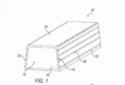
a figura 1 é uma vista em perspectiva de uma modalidade de um reforço tendo um suporte com uma característica de apoio que inclui uma pluralidade de nervuras, de acordo com uma modalidade;
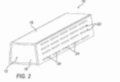
a figura 2 é uma vista em perspectiva de outra modalidade do reforço onde as nervuras são divididas em uma pluralidade de segmentos de nervura de acordo com uma modalidade;
a figura 3 é uma vista em perspectiva de outra modalidade do suporte em que as nervuras são divididas em uma pluralidade de segmentos de nervura correspondentes às posições de nervura internas do suporte de acordo com uma modalidade;
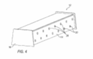
a figura 4 é uma vista em perspectiva de uma modalidade do suporte em que a característica de suporte inclui uma pluralidade de orifícios de acordo com uma modalidade;
a figura 5 é uma vista em perspectiva de outra modalidade do suporte em que a característica de apoio inclui a pluralidade de orifícios, de acordo com uma modalidade;
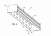
a figura 6 é uma vista em perspectiva do suporte da figura 5 em que duas cabeças de adesivo são dispostas sobre a pluralidade de orifícios, de acordo com uma modalidade;
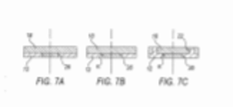
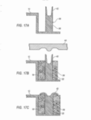
as figuras 7A-7C são vistas em seção transversal parcial do reforço dotados de várias características de apoio suportando um material es-ponjante estrutural ou acústico, de acordo com uma modalidade;
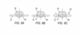
as figuras 8A-8C são vistas em seção transversal parcial do reforço tendo várias características e apoio suportando um adesivo de acordo com uma modalidade;
a figura 9 é uma vista em perspectiva de uma superfície do suporte em que a característica de apoio inclui a pluralidade de nervuras e uma pluralidade de pinos de acordo com uma modalidade;
a figura 10 é uma vista em seção transversal parcial do suporte disposto entre dois painéis e em que a característica de apoio inclui uma nervura dotada da pluralidade de orifícios e o material esponjante estrutural ou acústico disposto entre eles de acordo com uma modalidade;
a figura 11 é uma vista em seção transversal parcial do suporte disposto entre dois painéis e em que a característica de apoio inclui uma nervura dotada da pluralidade de orifícios e o adesivo entre elas interposto de acordo com uma modalidade;
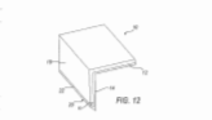
a figura 12 é uma vista em perspectiva do suporte em que a característica de apoio inclui uma nervura se estendendo de uma borda de uma parede perpendicular a uma direção de moldagem e uma inclinação em relação à parede de acordo com uma modalidade;
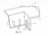
a figura 13 é uma vista em perspectiva do suporte em que a característica de apoio inclui nervuras se estendendo da parede paralela à direção de moldagem e a uma inclinação em relação à parede de acordo com uma modalidade;
a figura 14A é uma vista em perspectiva de ainda outra modalidade do suporte em que a característica de apoio inclui uma pluralidade de cunhas se estendendo de uma borda da parede, de acordo com uma modalidade;
a figura 14B é uma vista em perspectiva do suporte da figura 14A com o material esponjante estrutural ou acústico disposto sobre o suporte de acordo com uma modalidade;
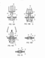
as figuras 15A-15D são vistas em corte transversal de um pino conector sendo inserido em um suporte e camada de material e deformado para fixar o suporte à camada de material, de acordo com uma modalidade;
a figura 16 é uma vista em corte transversal de um pino conector dotado de uma configuração diferente do pino conector das figuras 15A-15D sendo deformado para fixar o suporte à camada de material; de acordo com uma modalidade; e
as figuras 17A-17C são vistas laterais de um pino conector integralmente formado com o suporte de acordo com uma modalidade.The preceding description will be better understood from the detailed description of the following example drawings, where:
figure 1 is a perspective view of an embodiment of a reinforcement having a support with a support feature that includes a plurality of ribs, according to an embodiment;
figure 2 is a perspective view of another embodiment of the reinforcement where the ribs are divided into a plurality of rib segments according to one embodiment;
figure 3 is a perspective view of another embodiment of the support in which the ribs are divided into a plurality of rib segments corresponding to the internal rib positions of the support according to one embodiment;
figure 4 is a perspective view of an embodiment of the support in which the support feature includes a plurality of holes according to an embodiment;
figure 5 is a perspective view of another embodiment of the support in which the support feature includes the plurality of holes, according to one embodiment;
figure 6 is a perspective view of the support of figure 5 in which two adhesive heads are arranged over the plurality of holes, according to one embodiment;
figures 7A-7C are seen in partial cross-section of the reinforcement provided with various support characteristics supporting a structural or acoustic spongy material, according to a modality;
figures 8A-8C are seen in partial cross-section of the reinforcement having various characteristics and support supporting an adhesive according to an embodiment;
figure 9 is a perspective view of a support surface where the support feature includes the plurality of ribs and a plurality of pins according to an embodiment;
figure 10 is a partial cross-sectional view of the support arranged between two panels and in which the support feature includes a rib provided with a plurality of holes and the structural or acoustic spongy material arranged between them according to a modality;
Figure 11 is a partial cross-sectional view of the support arranged between two panels and in which the support feature includes a rib provided with a plurality of holes and the adhesive between them interposed according to an embodiment;
figure 12 is a perspective view of the support in which the support feature includes a rib extending from an edge of a wall perpendicular to a molding direction and an inclination with respect to the wall according to an embodiment;
figure 13 is a perspective view of the support in which the support feature includes ribs extending from the wall parallel to the molding direction and an inclination with respect to the wall according to an embodiment;
Figure 14A is a perspective view of yet another embodiment of the support in which the support feature includes a plurality of wedges extending from an edge of the wall, according to one embodiment;
figure 14B is a perspective view of the support of figure 14A with the structural or acoustic spongy material arranged on the support according to an embodiment;
figures 15A-15D are a cross-sectional view of a connector pin being inserted into a support and layer of material and deformed to fix the support to the layer of material, according to an embodiment;
figure 16 is a cross-sectional view of a connector pin provided with a different configuration from the connector pin of figures 15A-15D being deformed to fix the support to the material layer; according to a modality; and
figures 17A-17C are side views of a connector pin integrally formed with the support according to an embodiment.
Um reforço inclui uma camada de material disposta sobre o suporte. Em uma modalidade, o suporte inclui características de apoio integralmente formadas, tais como nervuras, pinos, orifícios, ou uma combina-ção dos mesmos, para auxiliar a suportar a camada de material. Em outra modalidade, a característica de apoio pode incluir um pino conector que se estende através do suporte e da camada de material, e deformar para manter os dois conjugados. A modificação da geometria de várias superfícies do suporte ou utilização do pino reduz a interface fraca entre a camada de material e o suporte pelo aperfeiçoamento da ligação da camada de material com o suporte.A reinforcement includes a layer of material arranged on the support. In one embodiment, the support includes integrally formed support features, such as ribs, pins, holes, or a combination thereof, to help support the material layer. In another embodiment, the support feature may include a connector pin that extends through the support and material layer, and deform to keep the two conjugated. Modifying the geometry of various surfaces of the support or using the pin reduces the weak interface between the material layer and the support by improving the connection of the material layer with the support.
Reportando-se às figuras, onde numerais idênticos indicam partes idênticas ou correspondentes através da totalidade das várias vistas, um reforço 10 inclui um suporte 12 com uma pluralidade de pares 14 se estendendo entre as extremidades terminais 16, e uma camada de material 18, tal como esponja estrutural, esponja acústica, ou um adesivo entre outros.Referring to the figures, where identical numerals indicate identical or corresponding parts across all of the various views, a reinforcement 10 includes a support 12 with a plurality of pairs 14 extending between the end ends 16, and a layer of material 18, such like structural sponge, acoustic sponge, or an adhesive among others.
A figura 1 é uma vista em perspectiva de uma modalidade do reforço 10. A camada de material 18 é disposta sobre as paredes 14 do suporte 12 e é pelo menos parcialmente suportada por uma característica de apoio 20 que é integralmente formada com o suporte 12. Na presente modalidade, a característica de apoio 20 inclui uma pluralidade de nervuras 22 integralmente formadas com e se estendendo de uma superfície de uma das paredes 14. Conforme ilustrado, as nervuras 22 são paralelas e espaçadas de uma borda da parede 14, e se estendem continuamente ao longo de uma extensão da parede 14 entre as extremidades terminais16 do suporte 12. Outrossim, as nervuras 22 são lateralmente mutuamente espaçadas. Por exemplo, as nervuras 22 podem ser orientadas perpendiculares ou oblíquas a uma direção de cisalhamento principal. A figura 2 é uma vista em perspectiva de outra modalidade do reforço 10 onde cada nervura 22 é dividida em uma pluralidade de segmentos de nervura 24 em linha com/ou lateralmente mutuamente espaçadas. Alternativamente, a figura 3 é uma vista em perspectiva de ainda outra modalidade do reforço10 onde cada nervura é dividida em uma pluralidade de segmentos de nervura 24 que correspondem com as posições de nervura internas do suporte 12. A camada de material 18 é então disposta sobre o suporte 12 entre cada um dos segmentos de nervura 24. Em uma e outra modalidade das figuras 1-3, a altura das nervuras 22 pode corresponder à espessura da camada do material 18. Por exemplo, a altura de materiais expansíveis, como material esponjante estrutural ou a-cústico, pode ser de 2-6 mm, e especificamente de 3-4 mm. Para adesivos, a altura pode ser de 0,5-6 mm, porém pode geralmente estar em torno de 2 mm. O comprimento da nervura 22 pode ser de 20 a 50 mm, e a distância entre cada nervura pode ser de 4 a 20 mm. Outrossim, as posições de nervura podem corresponder a um conjunto de nervuras principais internas (não mostradas) ou nervuras secundárias (não mostradas) formando o suporte estrutural 12.Figure 1 is a perspective view of a reinforcement embodiment 10. The layer of material 18 is arranged on the walls 14 of the support 12 and is at least partially supported by a support feature 20 which is integrally formed with the support 12. In the present embodiment, the support feature 20 includes a plurality of ribs 22 integrally formed with and extending from a surface of one of the walls 14. As shown, the ribs 22 are parallel and spaced from an edge of the wall 14, and extend continuously along an extension of the wall 14 between the terminal ends16 of the support 12. Furthermore, the ribs 22 are laterally spaced apart. For example, ribs 22 can be oriented perpendicularly or obliquely to a main shear direction. Figure 2 is a perspective view of another embodiment of the reinforcement 10 where each rib 22 is divided into a plurality of rib segments 24 in line with / or laterally spaced apart. Alternatively, figure 3 is a perspective view of yet another embodiment of the reinforcement10 where each rib is divided into a plurality of rib segments 24 that correspond to the internal rib positions of the support 12. The layer of material 18 is then arranged on the support 12 between each of the rib segments 24. In either embodiment of figures 1-3, the height of the ribs 22 may correspond to the thickness of the layer of material 18. For example, the height of expandable materials, such as foam material structural or a-acoustic, it can be 2-6 mm, and specifically 3-4 mm. For adhesives, the height can be 0.5-6 mm, but it can generally be around 2 mm. The length of the rib 22 can be 20 to 50 mm, and the distance between each rib can be 4 to 20 mm. Furthermore, the rib positions can correspond to a set of internal main ribs (not shown) or secondary ribs (not shown) forming the structural support 12.
Reportando-se a seguir à figura 4, em uma modalidade, as paredes 14 do suporte 12 definem uma pluralidade de orifícios 26 que podem ser usados para, pelo menos parcialmente, suportar a camada de material 18. Os orifícios 26 são dispostos sobre a superfície externa do suporte 12 e podem formar um padrão. Muitos padrões são possíveis, inclusive alinhar os orifícios 26, dispor os orifícios em uma configuração em zigzag ou dispersar aleatoriamente os orifícios ao longo do suporte 12. Outrossim, os orifícios 26 podem ter diferentes dimensões e configurações. Na modalidade da figura 4, os orifícios 26 são substancialmente circulares, e podem ter um diâmetro de 3 a 6 mm. Todavia, o diâmetro pode ser aumentado para 10 a 15 mm. Além disso, como mostrado, podem ser alongados (isto é, ter duas bordas arredondadas ligadas por dois lados substancialmente paralelos). Na presente modalidade, os orifícios 26 podem ter uma largura entre 2 a 5 mm e um comprimento entre 10 a 40 mm;Referring to figure 4, in one embodiment, the walls 14 of the support 12 define a plurality of holes 26 that can be used, at least partially, to support the layer of material 18. The holes 26 are arranged on the surface support 12 and can form a pattern. Many patterns are possible, including aligning the holes 26, arranging the holes in a zigzag configuration, or randomly dispersing the holes along the support 12. Furthermore, the holes 26 can have different dimensions and configurations. In the embodiment of figure 4, the holes 26 are substantially circular, and can have a diameter of 3 to 6 mm. However, the diameter can be increased to 10 to 15 mm. In addition, as shown, they can be elongated (i.e., having two rounded edges connected by two substantially parallel sides). In the present embodiment, the holes 26 can have a width between 2 to 5 mm and a length between 10 to 40 mm;
Reportando-se à figura 6, a camada de material 18 pode ser disposta nas paredes 14 sobre os orifícios 26 de modo que os orifícios 26 possam pelo menos parcialmente suportar a camada de material 18. Como ilustrado, a camada de material 18 é representada por duas contas de adesivo dispostas na parede sobre os orifícios 26, ainda que a camada de material 18 possa alternativamente ser de material esponjante estrutural ou acústico. Por exemplo, as figuras 7A-7C são vistas em corte transversal parcial do material esponjante estrutural ou acústico disposto sobre o suporte 12 e sendo sustentado pelos orifícios 26. Na figura 7A, os orifícios 26 podem ter bordas que são perpendiculares à superfície externa do suporte 12, ou como ilustrado nas figuras 7B e 7C, as bordas dos orifícios podem ser inclinadas em relação à superfície externa do suporte 12, por exemplo, o ângulo α pode ser de 10 a 30 graus. A inclinação das bordas permite que orifício 26 suporte melhor a camada de material 18 (isto é, o material esponjante estrutural ou acústico), especialmente após o cozimento. Outrossim, reportando-se à figura 7C, a característica de apoio 20 pode incluir uma combinação de orifícios 26 e nervuras 22 integralmente formados. De maneira similar, as figuras 8A-8C ilustram os mesmos princípios que as figuras 7A-7C, respectivamente, porém utilizando um adesivo como a camada de material 18. As modalidades das figuras 8B e 8C têm um ângulo similar α como nas figuras 7B e 7C
A figura 9 é uma vista em perspectiva de uma parte do reforço 10 onde a característica de apoio 20 inclui nervuras 22 e uma pluralidade de pinos 28 integralmente formados com e se estendendo de uma superfície de uma das paredes 14. Os pinos 28 podem ter um diâmetro de 2 a 4 mm e uma altura que geralmente corresponde à espessura da camada do material não expandido 18. Aquela altura pode ser de 2-6 mm para materiais expansíveis ou 0,5-6 mm para adesivos. A camada de material 18, ainda que não mostrado na figura 9, é pelo menos parcialmente apoiada sobre o suporte
12 pelos pinos 28. Pode ser apreciado que os pinos 28 podem ser usados em combinação com qualquer uma das modalidades prévias descritas. Por exemplo, os pinos 28 podem ser integralmente formados com as nervuras 22, ou integralmente formados sobre as paredes 14 munidas de orifícios 26.Referring to figure 6, the material layer 18 can be arranged on the walls 14 over the holes 26 so that the holes 26 can at least partially support the material layer 18. As illustrated, the material layer 18 is represented by two adhesive beads arranged on the wall over the holes 26, although the layer of material 18 may alternatively be of structural or acoustic sponge material. For example, figures 7A-7C are seen in partial cross-section of the structural or acoustic spongy material arranged on the support 12 and being supported by the holes 26. In figure 7A, the holes 26 can have edges that are perpendicular to the external surface of the support 12, or as illustrated in figures 7B and 7C, the edges of the holes can be inclined with respect to the external surface of the support 12, for example, the angle α can be 10 to 30 degrees. The inclination of the edges allows hole 26 to better support the layer of material 18 (i.e., the structural or acoustic spongy material), especially after cooking. Furthermore, referring to figure 7C, the support feature 20 can include a combination of integrally formed holes 26 and ribs 22. Similarly, figures 8A-8C illustrate the same principles as figures 7A-7C, respectively, but using an adhesive as the layer of material 18. The modalities of figures 8B and 8C have an angle similar to α as in figures 7B and 7C
Figure 9 is a perspective view of a part of the reinforcement 10 where the support feature 20 includes ribs 22 and a plurality of pins 28 integrally formed with and extending from a surface of one of the walls 14. The pins 28 can have a diameter from 2 to 4 mm and a height that generally corresponds to the layer thickness of the unexpanded material 18. That height can be 2-6 mm for expandable materials or 0.5-6 mm for adhesives. The layer of material 18, although not shown in figure 9, is at least partially supported on the support
12 by pins 28. It can be appreciated that pins 28 can be used in combination with any of the previous described modes. For example, pins 28 can be integrally formed with the ribs 22, or integrally formed on the walls 14 provided with holes 26.
Em uma modalidade, a camada de material 18 pode ser disposta sobre uma característica de suporte 20 entre dois painéis 30 de um produto sendo reforçado. As figuras 10 e11 são vistas em corte transversal de uma única nervura 22 definindo uma pluralidade de orifícios 26 e sendo disposta entre os dois painéis 30. Na presente modalidade, o suporte 12 pode ser uma única parede 14 de plástico ou metal que é aproximadamente equidistante entre os dois painéis 30. Aqui, a parede 14 constitui a característica de suporte 20 (isto é, a única nervura 22). A camada de material 18 é disposta sobre a nervura 22, e quando a camada de material se expande, preenche os orifícios 26 e o espaço entre os painéis 26 e o espaço entre os painéis 30 de tal maneira que a camada de material 18 conecta os dois painéis 30 através da parede 14. A figura 10 ilustra a presente modalidade com material esponjante acústico, e a figura 11 ilustra esta modalidade com o adesivo. Outrossim, ainda que não ilustrado, a característica de suporte 20 pode adicionalmente incluir a pluralidade de pinos 28 se estendendo das nervuras 22. As modalidades das figuras 10 e 11 podem ser usadas quando a distância entre os painéis 30 é estreita, tal como de 15 a 25 mm.In one embodiment, the material layer 18 can be arranged on a support feature 20 between two panels 30 of a product being reinforced. Figures 10 and 11 are seen in cross-section of a single rib 22 defining a plurality of holes 26 and being arranged between the two panels 30. In the present embodiment, the support 12 can be a single wall 14 of plastic or metal which is approximately equidistant between the two panels 30. Here, wall 14 constitutes support feature 20 (i.e., the only rib 22). The material layer 18 is arranged on the rib 22, and when the material layer expands, it fills the holes 26 and the space between the panels 26 and the space between the panels 30 in such a way that the material layer 18 connects the two panels 30 through the wall 14. Figure 10 illustrates the present modality with acoustic sponge material, and figure 11 illustrates this modality with the adhesive. Furthermore, although not shown, the support feature 20 can additionally include the plurality of pins 28 extending from the ribs 22. The modalities of figures 10 and 11 can be used when the distance between panels 30 is narrow, such as 15 to 25 mm.
A camada de material 18 é de maneira geral mais fraca nas bordas do suporte 12 porque a camada de material 18 e o suporte 12 tendem a se deslaminar durante o armazenamento, expedição, manipulação, e processamento. As figuras 12-14B ilustram modalidades para aperfeiçoar a interface entre a camada de material 18 e o suporte 12 nas bordas das paredes 14.The material layer 18 is generally weaker at the edges of the support 12 because the material layer 18 and the support 12 tend to slide off during storage, shipping, handling, and processing. Figures 12-14B illustrate modalities for improving the interface between the material layer 18 and the support 12 at the edges of the walls 14.
A figura 12 é uma vista parcial de uma modalidade do suporte 12 e camada de material 18. Na presente modalidade, o suporte 12 inclui a característica de suporte 20 integralmente formada com e se estendendo de uma borda de uma das paredes 14. Como na modalidade prévia, a camada de material 18 é disposta sobre a parede 14 e é pelo menos parcialmente sustentada pela característica de apoio 20. Especificamente, a característica de apoio 20 na presente modalidade é uma nervura se estendendo da borda de parede 14 a um ângulo α em relação à parede 14. O ângulo α pode ser qualquer ângulo que suporte a camada de material 18, tal como entre 10 graus e 60 graus, e especificamente entre 30 a 45 graus. Este desenho de inclinação de ângulo negativo deve ajudar a sustentar a camada de material 18 e reduzir qualquer interface fraca entre a borda do suporte 12 e a camada de material 18. Nessa modalidade, a nervura 22 deve se estender continuamente ao longo da borda da portadora 12, ou ser dividida em segmentos ao longo de várias seções da borda. Como mostrada na figura 12, as nervuras 22 se estendem a partir da parede 14 em uma direção perpendicular à uma direção de molde, mas este conceito também deve ser usado em suportes retirados 12 onde as nervuras 22 estão na direção retirada.Figure 12 is a partial view of an embodiment of the support 12 and layer of material 18. In the present embodiment, the support 12 includes the characteristic of support 20 integrally formed with and extending from an edge of one of the walls 14. As in the embodiment Previously, the layer of material 18 is arranged on the wall 14 and is at least partially supported by the support feature 20. Specifically, the support feature 20 in the present embodiment is a rib extending from the wall edge 14 at an angle α in in relation to the wall 14. The angle α can be any angle that supports the layer of material 18, such as between 10 degrees and 60 degrees, and specifically between 30 to 45 degrees. This negative angle slope design should help support material layer 18 and reduce any weak interface between support edge 12 and material layer 18. In this embodiment, rib 22 should extend continuously along the edge of the carrier 12, or be divided into segments along several sections of the edge. As shown in figure 12, the ribs 22 extend from the wall 14 in a direction perpendicular to a mold direction, but this concept should also be used on removed supports 12 where the ribs 22 are in the removed direction.
Alternativamente, em referência à figura 13, a nervura 22 deve se estender a partir da parede 14 em uma direção paralela a uma direção de moldagem. Como nas modalidades anteriores, a nervura 22 deve ser angulada relativa à parede 14 em qualquer ângulo que possa sustentar a camada de material 18, tais como entre 10 e 60 graus, e especificamente, entre 30 e 45 graus. Outrossim, múltiplas nervuras 22 podem ser usadas na presente modalidade. Por exemplo, a parede 14 pode incluir uma pluralidade de nervuras 22 mutuamente espaçadas e cada tendo os mesmos, complementares e/ou únicos ângulos. As nervuras 22 na presente modalidade podem ter várias alturas, tal como de 2 a 20 mm, e especificamente de 6 a 10 mm. A distância entre as nervuras 22 pode ser de 6 a 50 mm.Alternatively, with reference to figure 13, the rib 22 must extend from the wall 14 in a direction parallel to a molding direction. As in the previous embodiments, the rib 22 should be angled relative to the wall 14 at any angle that can support the layer of material 18, such as between 10 and 60 degrees, and specifically, between 30 and 45 degrees. Furthermore, multiple ribs 22 can be used in the present embodiment. For example, wall 14 may include a plurality of ribs 22 mutually spaced and each having the same, complementary and / or unique angles. The ribs 22 in the present embodiment can have various heights, such as from 2 to 20 mm, and specifically from 6 to 10 mm. The distance between the ribs 22 can be from 6 to 50 mm.
Em outra modalidade, em vez de uma nervura 22 se estendendo da borda da parede 14, reportando-se às figuras 14A e 14B, a característica de apóio 20 pode incluir uma pluralidade de partes de cunha 32 se estendendo da borda. As partes em cunha 32 têm uma borda chanfrada 34 e são mutuamente espaçadas para auxiliar a reter a camada de material 18. Isto significa que a parte em cunha tem uma seção aberta que é menor sobre a superfície externa do suporte 12 em contato com a camada de material 18 do que sobre a superfície interna. De maneira geral, a largura da parte em cunha pode ser de 5 a 20 mm e a profundidade pode ser de 2 a 5 mm. A figura 14B ilustra a camada de material 18 disposta sobre o suporte 12 e interagindo com as partes em cunha 32. Muito embora, material esponjante estrutural ou acústico seja ilustrado, o adesivo também pode ser usado com as características de apoio 20 descritas na modalidade das figuras 14A e 14B.In another embodiment, instead of a rib 22 extending from the edge of the wall 14, referring to figures 14A and 14B, the support feature 20 may include a plurality of wedge parts 32 extending from the edge. The wedge parts 32 have a beveled edge 34 and are mutually spaced to help retain the layer of material 18. This means that the wedge part has an open section that is smaller on the outer surface of the support 12 in contact with the layer material 18 than on the inner surface. In general, the width of the wedge part can be 5 to 20 mm and the depth can be 2 to 5 mm. Figure 14B illustrates the layer of material 18 arranged on the support 12 and interacting with the wedge parts 32. Although the structural or acoustic spongy material is illustrated, the adhesive can also be used with the support characteristics 20 described in the modality of the figures 14A and 14B.
Em vez de formar integralmente as características de suporte 20 com as paredes 14 do suporte 12, em outra modalidade, um pino conector 36 pode ser usado para conectar o suporte 12 com a camada de material 18. Uma modalidade dessa natureza pode ser útil quando a camada de material 18 tem reduzidas propriedades adesivas. Reportando-se às figuras 15A-15D, o pino conector 36 inclui uma parte rígida 38 configurada para se es-tender através de um orifício no suporte 12 e da camada de material 18. Como ilustrado, a parte rígida 38 tem uma seção transversal cilíndrica, ainda que a parte rígida 38 possa ter outras configurações. Uma parte de cabeça 40 é integralmente formada com a parte rígida 38 e repousa quer sobre o suporte 12 quer sobre a camada de material 18. A parte de cabeça 40 tem uma periferia geralmente circular e é arredondada sobre pelo menos um lado. O pino conector 36 ainda inclui uma parte deformável 42 integralmente formada com e adjacente à parte rígida 38 oposta à parte de cabeça 40. A parte deformável 42 tem uma seção transversal cilíndrica que é pelo menos parcialmente oca e aberta em uma extremidade.Instead of forming integrally the support characteristics 20 with the walls 14 of the support 12, in another embodiment, a connector pin 36 can be used to connect the support 12 with the layer of material 18. Such an embodiment can be useful when the material layer 18 has reduced adhesive properties. Referring to figures 15A-15D, the connector pin 36 includes a rigid part 38 configured to extend through a hole in the support 12 and the layer of material 18. As illustrated, the rigid part 38 has a cylindrical cross section , although rigid part 38 may have other configurations. A head part 40 is integrally formed with the rigid part 38 and rests on either the support 12 or the layer of material 18. The head part 40 has a generally circular periphery and is rounded on at least one side. The connector pin 36 further includes a deformable part 42 integrally formed with and adjacent to the rigid part 38 opposite the head part 40. The deformable part 42 has a cylindrical cross section that is at least partially hollow and open at one end.
Uma ferramenta 44 pode ser usada para inserir o pino conector 36 no interior dos orifícios do suporte 12 e a camada de material 18, e deformar o pino conector 36 para afixar o suporte 12 e camada de material 18. Como mostrado na figura 15A, a ferramenta 44 pode efetuar a preensão da parte de cabeça 40 do pino conector 36, e como ilustrado na figura 15B, a ferramenta 44 pode inserir o pino conector 36 nos orifícios alinhados 26 definidos pelo suporte 12 e pela camada de material 18. Além disso, a ferramenta pode ser inserida no interior da parte deformável 42 do pino conector 36, e deformar o pino conector 36 pela aplicação de uma primeira força F1 à parte deformável 42 do pino conector 36 e simultaneamente aplicar uma segunda força F2 à parte de cabeça 40 do pino de conexão 36 em uma direção oposta à primeira força F1, como ilustrado nas figuras 15B e 15C. Desta maneira, a ferramenta 44 aplica a primeira força F1 contra uma superfície interna da parte deformável 42, que faz a parte deformável 42 flexionar-se em sentido contrário ao centro do pino conector 36 e manter a camada de material 18 contra o suporte 12, como ilustrado na figura 15D. Em outra modalidade, o pino conector 36 pode ter uma configuração tubular antes de ser deformado, e ambas as extremidades do pino conector 36 podem ser deformadas como ilustrado com respeito à parte deformável 42 das figuras 15A-15D. Nesta modalidade, a ferramenta 44 aplicaria forças contra a superfície interna do pino conector 36 em ambas as extremidades. Alternativamente, reportando-se a seguir à figura 16, o pino conector 36 pode ter uma configuração cilín-drica substancialmente sólida antes de ser deformado e ser disposto no orificio definido pelo suporte 12 e a camada de material 18. Nesta modalidade, a ferramenta 44 pode ser usada para deformar ambas as extremidades do pino conector 36 para fixar o suporte 12 à camada de material 18. Especificamente, em vez de curvar partes do pino conector 36 em sentido contrário ao centro do pino conector 36, nesta modalidade, as duas extremidades do pino conector 36 são flexionadas em torno do suporte 12 e da camada de material 18.A tool 44 can be used to insert the connector pin 36 into the holes of the support 12 and the layer of material 18, and deform the connector pin 36 to affix the support 12 and layer of material 18. As shown in figure 15A, the tool 44 can hold the head part 40 of the connector pin 36, and as illustrated in figure 15B, tool 44 can insert the connector pin 36 into the aligned holes 26 defined by the support 12 and the material layer 18. In addition, the tool can be inserted into the deformable part 42 of the connector pin 36, and deform the connector pin 36 by applying a first force F1 to the deformable part 42 of the connector pin 36 and simultaneously apply a second force F2 to the head part 40 of the connecting pin 36 in a direction opposite to the first force F1, as shown in figures 15B and 15C. In this way, tool 44 applies the first force F1 against an internal surface of the deformable part 42, which causes the deformable part 42 to flex in the opposite direction to the center of the connector pin 36 and to keep the material layer 18 against the support 12, as illustrated in figure 15D. In another embodiment, the connector pin 36 can have a tubular configuration before being deformed, and both ends of the connector pin 36 can be deformed as illustrated with respect to the deformable part 42 of figures 15A-15D. In this embodiment, tool 44 would apply forces against the inner surface of connector pin 36 at both ends. Alternatively, referring to figure 16, the connector pin 36 can have a substantially solid cylindrical configuration before being deformed and being disposed in the hole defined by the support 12 and the material layer 18. In this embodiment, the tool 44 can be used to deform both ends of the connector pin 36 to secure the support 12 to the layer of material 18. Specifically, instead of bending parts of the connector pin 36 in the opposite direction to the center of the connector pin 36, in this embodiment, the two ends connector pin 36 are flexed around the support 12 and the material layer 18.
Em ainda outra modalidade, o pino conector 36 pode ser integralmente formado com o suporte 12, como ilustrado nas figuras 17A-17C. O pino conector 36 nesta modalidade pode incluir a parte rígida 38 e a parte deformável 42. Como ilustrado na figura 17B, a camada de material 18 pode ser disposta sobre o suporte em torno do pino conector 36. Então, a ferramenta 44 pode ser usada para deformar a parte deformável 42 para fixar a camada de material 18 ao suporte 12. Alternativamente, o pino conector 36 tendo uma configuração tubular ou cilíndrica substancialmente sólida pode ser integralmente formado com o suporte 12 e deformado pela ferramenta 44.In yet another embodiment, the connector pin 36 can be integrally formed with the support 12, as illustrated in figures 17A-17C. The connector pin 36 in this embodiment can include the rigid part 38 and the deformable part 42. As illustrated in figure 17B, the layer of material 18 can be arranged on the support around the connector pin 36. Then, the tool 44 can be used to deform the deformable part 42 to fix the layer of material 18 to the support 12. Alternatively, the connector pin 36 having a substantially solid tubular or cylindrical configuration can be integrally formed with the support 12 and deformed by the tool 44.
Várias combinações de características de apoio 20 podem ser usadas sobre qualquer suporte 12. Por exemplo, quando forças de cisalha-mento ou de tração prevalecem, um conjunto de nervuras 22 em combinação com os pinos 28 pode ser ideal. No entanto, quando forças de tração predominam, um conjunto de nervuras 22, orifícios 26, e pinos 28 pode ser ideal. É apreciado que outras combinações de características de apoio podem ser usadas ou ideais nestas ou outras situações. Além disso, o pino conector 36 pode ser usado com qualquer uma das modalidades prévias onde a característica de apoio 20 é integralmente formada com o suporte 12.Various combinations of support characteristics 20 can be used on any support 12. For example, when shear or tensile forces prevail, a set of ribs 22 in combination with pins 28 may be ideal. However, when tensile forces predominate, a set of ribs 22, holes 26, and pins 28 may be ideal. It is appreciated that other combinations of supporting characteristics can be used or ideal in these or other situations. In addition, the connector pin 36 can be used with any of the previous modes where the support feature 20 is integrally formed with the support 12.
Além das modalidades descritas, as paredes 14 do suporte 12 podem ser tratadas com tratamento de superfície para aperfeiçoar a ligação da camada de material 18 com o suporte 12. Por exemplo, o tratamento da superfície pode ser usado para aperfeiçoar a ligação de material esponjante estrutural com suportes de plástico ou metal 12, ou o adesivo com suportes de plástico ou metal. Vários tratamentos de superfície incluem jato de areia, o uso de um adesivo, decapagem química,
o uso de plasma, a utilização de uma descarga em corona, flamejante, ação de abrasão adesiva, ataque por ácido crômico, tratamento por iodo, o uso de iniciadores, tratamento sódico, enxertos superficiais, rugosidade de superfícies, tratamento térmico, crescimento transcristalino, e/ou exposição à UV. O tratamento da superfície pode também auxiliar a aperfeiçoar a ligação de outros materiaisIn addition to the described embodiments, the walls 14 of the support 12 can be treated with surface treatment to improve the connection of the material layer 18 with the support 12. For example, the surface treatment can be used to improve the connection of structural sponge material with plastic or metal supports 12, or the adhesive with plastic or metal supports. Various surface treatments include sandblasting, the use of an adhesive, chemical pickling,
the use of plasma, the use of a corona discharge, flaming, adhesive abrasion action, chromic acid attack, iodine treatment, the use of initiators, sodium treatment, surface grafts, surface roughness, heat treatment, transcrystalline growth, and / or UV exposure. Surface treatment can also help to improve the bonding of other materials
A descrição acima é proposta para ser ilustrativa e não restritiva. Muitas abordagens ou aplicações alternativas além dos exemplos apresentados se evidenciarão àqueles versados na técnica da leitura da descrição acima. O escopo da invenção deve ser determinado não com referência à descrição acima, porém em vez disso, deve ser determinado com referência às reivindicações apensas, juntamente com o pleno escopo de equivalentes, aos quais as ditas reivindicações são intituladas. É antecipado e proposto que futuros desenvolvimentos se apresentarão àqueles versados na técnica, e que os sistemas e métodos expostos serão incorporados aos ditos sistemas futuros. Em suma, deve ser entendido que a invenção é suscetível de modificações e variações e que é limitada somente pelas reivindicações indicadas.The above description is proposed to be illustrative and not restrictive. Many alternative approaches or applications in addition to the examples presented will become evident to those versed in the technique of reading the description above. The scope of the invention must be determined not with reference to the above description, but instead, it must be determined with reference to the attached claims, together with the full scope of equivalents, to which the said claims are entitled. It is anticipated and proposed that future developments will present themselves to those skilled in the art, and that the systems and methods exposed will be incorporated into said future systems. In short, it should be understood that the invention is susceptible to modifications and variations and that it is limited only by the stated claims.
As presentes modalidades foram particularmente ilustradas e descritas que são meramente ilustrativas das modalidades ideais. Deve ser entendido pelos versados na técnica que várias alternativas às modalidades descritas podem ser empregadas nas realização das reivindicações sem se afastar do espírito e escopo conforme definido nas reivindicações que seguem. É proposto que as reivindicações a seguir definam o escopo da invenção e que o método e aparelho dentro do escopo destas reivindicações e seus equivalentes sejam desse modo abrangidos. A presente descrição deve ser entendida de modo a abranger todas as novas e não óbvias combinações de elementos aqui descritos, e as reivindicações podem ser apresentadas neste ou em um pedido posterior para qualquer nova e não óbvia combinação destes elementos. Outrossim, as modalidades precedentes são ilus-trativas e nenhuma característica ou elemento individual é essencial em todas as possíveis combinações que podem ser reivindicadas neste ou em um pedido posterior.The present modalities have been particularly illustrated and described which are merely illustrative of the ideal modalities. It should be understood by those skilled in the art that various alternatives to the described modalities can be used in making the claims without departing from the spirit and scope as defined in the claims that follow. It is proposed that the following claims define the scope of the invention and that the method and apparatus within the scope of these claims and their equivalents are thereby covered. The present description should be understood to cover all new and non-obvious combinations of elements described herein, and claims can be made in this or a subsequent application for any new and non-obvious combination of these elements. Furthermore, the preceding modalities are illustrative and no individual feature or element is essential in all possible combinations that can be claimed in this or a subsequent application.
Todos os termos usados nas reivindicações são propostos para receber suas construções razoáveis mais amplas e seu significado usual conforme entendido pelos versados na técnica salvo se uma indicação explicita em contrário for aqui realizada. Particularmente, o uso de artigos singulares tais como "um", "o" ou "dito" etc; deve ser interpretado para enumerar um ou mais dos ditos elementos, salvo se uma reivindicação recitar uma limitação explícita em contrário.All terms used in the claims are proposed to receive their broadest reasonable constructions and their usual meaning as understood by those skilled in the art unless an explicit statement to the contrary is made herein. In particular, the use of singular articles such as "one", "o" or "said" etc; it must be interpreted to enumerate one or more of said elements, unless a claim recites an explicit limitation to the contrary.
Claims (16)
um suporte (12) tendo uma pluralidade de paredes (14) se estendendo entre extremidades terminais (16); uma característica de apoio (20) disposta sobre o dito suporte (12); e
uma camada de material (18) disposta sobre pelo menos uma da dita pluralidade de paredes (14) e pelo menos parcialmente suportada pela dita característica de apoio (20),
em que dita característica de apoio (20) inclui pelo menos uma nervura (22) integralmente formada com dito suporte (12),
caracterizado pelo fato de que a dita pelo menos uma nervura (22) se estende a um ângulo α em relação à dita parede (14).Reinforcement (10) comprising:
a support (12) having a plurality of walls (14) extending between terminal ends (16); a support feature (20) arranged on said support (12); and
a layer of material (18) arranged on at least one of said plurality of walls (14) and at least partially supported by said support feature (20),
wherein said support characteristic (20) includes at least one rib (22) integrally formed with said support (12),
characterized by the fact that said at least one rib (22) extends at an angle α in relation to said wall (14).
um suporte (12) tendo uma pluralidade de paredes (14) se estendendo entre extremidades terminais (16); uma característica de apoio (20) disposta sobre o dito suporte (12); e
uma camada de material (18) disposta sobre pelo menos uma da dita pluralidade de paredes (14) e pelo menos parcialmente suportada pela dita característica de apoio (20),
em que dita característica de apoio (20) inclui uma pluralidade de orifícios (26) definidos pelas ditas paredes (14),
caracterizado pelo fato de que as bordas do orifício (26) se estende a um ângulo α em relação à dita parede (14).Reinforcement (10) comprising:
a support (12) having a plurality of walls (14) extending between terminal ends (16); a support feature (20) arranged on said support (12); and
a layer of material (18) arranged on at least one of said plurality of walls (14) and at least partially supported by said support feature (20),
wherein said support feature (20) includes a plurality of holes (26) defined by said walls (14),
characterized by the fact that the edges of the hole (26) extends at an angle α in relation to said wall (14).
Applications Claiming Priority (3)
| Application Number | Priority Date | Filing Date | Title |
|---|---|---|---|
| EP08161173.3A EP2147848B1 (en) | 2008-07-25 | 2008-07-25 | Interconnected foam or adhesive layers |
| EP08161173.3 | 2008-07-25 | ||
| PCT/EP2009/059534 WO2010010167A1 (en) | 2008-07-25 | 2009-07-24 | Interconnected foam or adhesive layers |
Publications (2)
| Publication Number | Publication Date |
|---|---|
| BRPI0916859A2 BRPI0916859A2 (en) | 2016-02-10 |
| BRPI0916859B1 true BRPI0916859B1 (en) | 2020-07-21 |
Family
ID=40278981
Family Applications (1)
| Application Number | Title | Priority Date | Filing Date |
|---|---|---|---|
| BRPI0916859-1A BRPI0916859B1 (en) | 2008-07-25 | 2009-07-24 | reinforcement of bonded adhesive layers or sponge material |
Country Status (8)
| Country | Link |
|---|---|
| US (1) | US9216774B2 (en) |
| EP (1) | EP2147848B1 (en) |
| JP (2) | JP2011529160A (en) |
| KR (1) | KR20110036116A (en) |
| CN (1) | CN102099240A (en) |
| BR (1) | BRPI0916859B1 (en) |
| ES (1) | ES2579228T3 (en) |
| WO (1) | WO2010010167A1 (en) |
Families Citing this family (27)
| Publication number | Priority date | Publication date | Assignee | Title |
|---|---|---|---|---|
| US8966766B2 (en) * | 2007-10-25 | 2015-03-03 | Zephyros, Inc. | Reinforcement structure and method employing bulkheads |
| WO2011146793A1 (en) | 2010-05-21 | 2011-11-24 | Zephyros,Inc. | Method for application of structural materials |
| BR112013013989B1 (en) | 2010-12-08 | 2022-02-08 | Zephyros, Inc | SEALING DEVICE FOR A CAVITY AND METHOD FOR SEALING A CAVITY |
| CN103857511B (en) | 2011-06-17 | 2016-01-20 | 泽菲罗斯公司 | Cavity black box |
| US8918983B2 (en) | 2011-06-21 | 2014-12-30 | Zephyros, Inc. | Integrated fastening system |
| WO2013082238A1 (en) | 2011-11-29 | 2013-06-06 | Zephyros, Inc. | Multi-part insert |
| BR112014018055A8 (en) | 2012-03-20 | 2017-07-11 | Zephyros Inc | DEFLECTOR ASSEMBLY |
| GB201207481D0 (en) | 2012-04-26 | 2012-06-13 | Zephyros Inc | Applying flowable materials to synthetic substrates |
| US8926005B2 (en) | 2012-05-24 | 2015-01-06 | Zephyros, Inc. | Vehicle body structure cut zones |
| CN104349972B (en) | 2012-06-08 | 2018-02-02 | 泽费罗斯股份有限公司 | Block piece with expandable material |
| EP4145441A1 (en) | 2012-12-21 | 2023-03-08 | Sika Technology AG | Insulating element, expanded insulating element, use of such an element and method for insulating |
| US20140322464A1 (en) * | 2013-04-26 | 2014-10-30 | Zephyros, Inc. | Activatable material and carrier attachment |
| EP3063053B1 (en) | 2013-10-31 | 2020-02-12 | Sika Technology AG | Baffle or reinforcement element for sealing and/or reinforcing a cavity and method for producing such a baffle or reinforcement element |
| US10427346B2 (en) | 2014-04-30 | 2019-10-01 | Zephyros, Inc. | Extruded reinforcements |
| BR112016027119B1 (en) | 2014-05-19 | 2022-05-31 | Zephyros, Inc | Method and device for reinforcement |
| EP3263425B1 (en) | 2016-06-27 | 2020-08-12 | Sika Technology AG | Insulation element |
| EP3487749B1 (en) | 2016-07-21 | 2021-10-06 | Zephyros, Inc. | Reinforcement structure |
| CN109982917B (en) | 2016-07-28 | 2022-04-05 | 泽菲罗斯有限公司 | Multi-stage deformation reinforcement structure for absorbing impact |
| US10940896B2 (en) | 2017-01-11 | 2021-03-09 | Zephyros, Inc. | Reinforcing devices |
| CN110603188A (en) * | 2017-04-21 | 2019-12-20 | Sika技术股份公司 | Reinforcing element |
| WO2018223139A1 (en) | 2017-06-02 | 2018-12-06 | Zephyros, Inc. | Anti-flutter baffle |
| EP3665068B1 (en) | 2017-08-07 | 2021-04-14 | Sika Technology AG | System of a sealed and reinforced structural element |
| EP3710339B1 (en) | 2017-11-14 | 2022-08-10 | Sika Technology AG | Device for reinforcing, sealing or damping of a structural element |
| EP3486146B1 (en) | 2017-11-15 | 2021-04-14 | Sika Technology Ag | Device for reinforcing and sealing a structural element |
| WO2019096694A1 (en) | 2017-11-15 | 2019-05-23 | Sika Technology Ag | Device for reinforcing a structural element |
| WO2019096693A1 (en) | 2017-11-15 | 2019-05-23 | Sika Technology Ag | Device for reinforcing, sealing, or damping a structural element |
| EP3936354B1 (en) * | 2020-07-08 | 2023-08-30 | Autotech Engineering S.L. | Chassis component for a motor vehicle |
Family Cites Families (32)
| Publication number | Priority date | Publication date | Assignee | Title |
|---|---|---|---|---|
| JPS5374564U (en) * | 1976-11-24 | 1978-06-21 | ||
| JP2551787Y2 (en) * | 1992-02-24 | 1997-10-27 | 三菱化学ビーエーエスエフ株式会社 | Civil and architectural structural members |
| US5534329A (en) | 1994-07-14 | 1996-07-09 | Bunimovich; Haim | Composite structure |
| JPH08207198A (en) * | 1995-02-08 | 1996-08-13 | Ig Tech Res Inc | Steel panel |
| JP3225394B2 (en) * | 1996-08-07 | 2001-11-05 | 親 中矢 | Equipment for attaching decorative blocks to concrete products |
| US5857244A (en) | 1997-07-30 | 1999-01-12 | General Motors Corporation | Fastener with molded-on compliant seal |
| US6093358A (en) | 1998-01-27 | 2000-07-25 | Lear Corporation | Method of making an expandable gap filling product |
| US6247287B1 (en) * | 1998-08-05 | 2001-06-19 | Neo-Ex Lab, Inc. | Structure and method for closing and reinforcing hollow structural members |
| JP2000052445A (en) * | 1998-08-06 | 2000-02-22 | Neoex Lab Inc | Hollow chamber shut-off tool in hollow structure |
| US6131897A (en) | 1999-03-16 | 2000-10-17 | L & L Products, Inc. | Structural reinforcements |
| JP4476438B2 (en) * | 1999-11-12 | 2010-06-09 | 株式会社ネオックスラボ | Hollow structure reinforcement |
| US6253524B1 (en) | 2000-01-31 | 2001-07-03 | Sika Corporation | Reinforcing member with thermally expansible structural reinforcing material and directional shelf |
| US6305136B1 (en) | 2000-01-31 | 2001-10-23 | Sika Corporation | Reinforcing member with beam shaped carrier and thermally expansible reinforcing material |
| US6475577B1 (en) | 2000-02-07 | 2002-11-05 | Sika Corporation | Reinforcing member with intersecting support legs |
| EP1268164B1 (en) * | 2000-03-03 | 2003-08-13 | Proteus GmbH | Component consisting of a fibre-reinforced synthetic material and a method for producing same |
| JP2002012167A (en) * | 2000-04-26 | 2002-01-15 | Neoex Lab Inc | Reinforcing structure of hollow structure and reinforcing tool therefor |
| JP2001310759A (en) | 2000-04-26 | 2001-11-06 | Neoex Lab Inc | Implement and method for reinforcing hollow structure |
| US6413611B1 (en) | 2000-05-01 | 2002-07-02 | Sika Corporation | Baffle and reinforcement assembly |
| JP2002029449A (en) * | 2000-07-17 | 2002-01-29 | Neoex Lab Inc | Reinforcing implement and reinforcing structure for hollow structure |
| DE10112688A1 (en) * | 2001-03-16 | 2002-09-26 | Sika Ag, Vormals Kaspar Winkler & Co | Reinforcement for vehicle bodywork pillars, and other hollow components, is a strengthening skeleton of injection molded heat-resistant plastics with support surfaces held by lateral ribs and longitudinal bars |
| GB2375328A (en) * | 2001-05-08 | 2002-11-13 | L & L Products | Reinforcing element for hollow structural member |
| AU2002313298A1 (en) * | 2002-06-28 | 2004-01-19 | Hayashi-Sika Automotive Ltd. | Body reinforcing material arrangement structure |
| DE10260572B4 (en) | 2002-12-21 | 2017-01-26 | Volkswagen Ag | Stiffening element, hollow beam and method for producing such |
| US6939123B2 (en) * | 2002-12-26 | 2005-09-06 | 3M Innovative Properties Company | Electroformed adhesive laminated tooling surface with precision structured interfaces |
| US7404996B2 (en) | 2004-04-08 | 2008-07-29 | International Automotive Components Group North America, Inc. | Two-shot polymeric component with attachment feature and method of producing same |
| US20060165482A1 (en) * | 2005-01-11 | 2006-07-27 | Olberding David J | Novel enhanced apparatus and method connecting structural members |
| FR2890133B1 (en) * | 2005-08-26 | 2009-01-30 | Haute Garonne Ets Autiol Et Ci | BLIND RIVET AND ITS REMOVAL METHOD |
| US8087916B2 (en) * | 2005-12-15 | 2012-01-03 | Cemedine Henkel Co., Ltd. | Holding jig for a foamable material |
| US7913467B2 (en) | 2006-07-25 | 2011-03-29 | Zephyros, Inc. | Structural reinforcements |
| US7673930B2 (en) | 2006-12-22 | 2010-03-09 | Sika Technology Ag | RT reinforcer |
| US8123284B2 (en) | 2007-01-11 | 2012-02-28 | Ford Motor Company | Vehicle body component and mating feature |
| US20080202674A1 (en) * | 2007-02-28 | 2008-08-28 | L&L Products, Inc. | Structural reinforcements |
-
2008
- 2008-07-25 ES ES08161173.3T patent/ES2579228T3/en active Active
- 2008-07-25 EP EP08161173.3A patent/EP2147848B1/en not_active Revoked
-
2009
- 2009-07-24 JP JP2011519180A patent/JP2011529160A/en active Pending
- 2009-07-24 KR KR1020117003480A patent/KR20110036116A/en not_active Application Discontinuation
- 2009-07-24 CN CN2009801280524A patent/CN102099240A/en active Pending
- 2009-07-24 WO PCT/EP2009/059534 patent/WO2010010167A1/en active Application Filing
- 2009-07-24 BR BRPI0916859-1A patent/BRPI0916859B1/en not_active IP Right Cessation
- 2009-07-24 US US13/055,869 patent/US9216774B2/en active Active
-
2014
- 2014-11-04 JP JP2014224269A patent/JP2015108447A/en active Pending
Also Published As
| Publication number | Publication date |
|---|---|
| US9216774B2 (en) | 2015-12-22 |
| KR20110036116A (en) | 2011-04-06 |
| JP2015108447A (en) | 2015-06-11 |
| ES2579228T3 (en) | 2016-08-08 |
| EP2147848A1 (en) | 2010-01-27 |
| US20110189428A1 (en) | 2011-08-04 |
| EP2147848B1 (en) | 2016-03-30 |
| JP2011529160A (en) | 2011-12-01 |
| BRPI0916859A2 (en) | 2016-02-10 |
| CN102099240A (en) | 2011-06-15 |
| WO2010010167A1 (en) | 2010-01-28 |
Similar Documents
| Publication | Publication Date | Title |
|---|---|---|
| BRPI0916859B1 (en) | reinforcement of bonded adhesive layers or sponge material | |
| EP1767441A2 (en) | Foam filling member | |
| BRPI0918435B1 (en) | structural reinforcement system | |
| JP2011530450A5 (en) | ||
| US10898138B2 (en) | Flexible patch including a plurality of through holes which can be adhered to skin and method for manufacturing the same | |
| BRPI0608646B1 (en) | PROVISION AND METHOD TO ORDER A WEAR RESISTANT AND NOISE REDUCTION OF WEAR ELEMENTS IN MATERIAL HANDLING SYSTEMS EXPOSED TO WEAR AND NOISE | |
| JP6546913B2 (en) | Fastener | |
| BRPI1003016A2 (en) | structural reinforcement with bonding material on orthogonal surfaces | |
| KR20120018644A (en) | Apparatus for transferring semiconductor package | |
| US20170047560A1 (en) | Exterior package for flexible electrochemical device and electrochemical device including the exterior package | |
| BRPI1002948A2 (en) | structural reinforcement applied to Structural Limb Clipping Area | |
| ES2175476T3 (en) | CONSTRUCTION ELEMENT AUTOPORTANTE PLASTICO EXPANDIDO, IN PARTICULAR FOR THE MANUFACTURE OF FLOOR AND WALL ELEMENTS FOR BUILDINGS IN GENERAL. | |
| JP5936080B2 (en) | Reinforcing element for casting including ring-shaped part and reinforcing material using such reinforcing element | |
| JPH0548218A (en) | Flexible printed circuit | |
| JP2001115416A (en) | Connection structure of floating body for floating pier | |
| CN108298197B (en) | Packaging structure and packaging method | |
| JP6077443B2 (en) | Reinforcing member aligned with load axis | |
| BR112019013791B1 (en) | STRUCTURAL REINFORCEMENT AND METHOD FOR FORMING A STRUCTURAL REINFORCEMENT | |
| JP2001253001A (en) | Frp molded object | |
| JP2023056200A (en) | storage rack | |
| KR200200669Y1 (en) | Connecting Structures of Aircraft Parts | |
| JP6877903B2 (en) | Simple partition | |
| JP3599410B2 (en) | Reinforced structure of resin molded product | |
| JPS62227636A (en) | Manufacture of honeycomb panel structure | |
| JP2000295731A (en) | Wiring harness protector |
Legal Events
| Date | Code | Title | Description |
|---|---|---|---|
| B06F | Objections, documents and/or translations needed after an examination request according [chapter 6.6 patent gazette] | ||
| B06T | Formal requirements before examination [chapter 6.20 patent gazette] | ||
| B06A | Patent application procedure suspended [chapter 6.1 patent gazette] | ||
| B09A | Decision: intention to grant [chapter 9.1 patent gazette] | ||
| B16A | Patent or certificate of addition of invention granted [chapter 16.1 patent gazette] |
Free format text: PRAZO DE VALIDADE: 10 (DEZ) ANOS CONTADOS A PARTIR DE 21/07/2020, OBSERVADAS AS CONDICOES LEGAIS. |
|
| B21F | Lapse acc. art. 78, item iv - on non-payment of the annual fees in time |
Free format text: REFERENTE A 13A ANUIDADE. |
|
| B24J | Lapse because of non-payment of annual fees (definitively: art 78 iv lpi, resolution 113/2013 art. 12) |
Free format text: EM VIRTUDE DA EXTINCAO PUBLICADA NA RPI 2680 DE 17-05-2022 E CONSIDERANDO AUSENCIA DE MANIFESTACAO DENTRO DOS PRAZOS LEGAIS, INFORMO QUE CABE SER MANTIDA A EXTINCAO DA PATENTE E SEUS CERTIFICADOS, CONFORME O DISPOSTO NO ARTIGO 12, DA RESOLUCAO 113/2013. |