BRPI0909094B1 - needle safety device and intravenous catheter device - Google Patents
needle safety device and intravenous catheter device Download PDFInfo
- Publication number
- BRPI0909094B1 BRPI0909094B1 BRPI0909094-0A BRPI0909094A BRPI0909094B1 BR PI0909094 B1 BRPI0909094 B1 BR PI0909094B1 BR PI0909094 A BRPI0909094 A BR PI0909094A BR PI0909094 B1 BRPI0909094 B1 BR PI0909094B1
- Authority
- BR
- Brazil
- Prior art keywords
- needle
- safety device
- jaw
- needle safety
- base portion
- Prior art date
Links
Images
Classifications
-
- A—HUMAN NECESSITIES
- A61—MEDICAL OR VETERINARY SCIENCE; HYGIENE
- A61M—DEVICES FOR INTRODUCING MEDIA INTO, OR ONTO, THE BODY; DEVICES FOR TRANSDUCING BODY MEDIA OR FOR TAKING MEDIA FROM THE BODY; DEVICES FOR PRODUCING OR ENDING SLEEP OR STUPOR
- A61M25/00—Catheters; Hollow probes
- A61M25/01—Introducing, guiding, advancing, emplacing or holding catheters
- A61M25/06—Body-piercing guide needles or the like
- A61M25/0612—Devices for protecting the needle; Devices to help insertion of the needle, e.g. wings or holders
- A61M25/0618—Devices for protecting the needle; Devices to help insertion of the needle, e.g. wings or holders having means for protecting only the distal tip of the needle, e.g. a needle guard
-
- A—HUMAN NECESSITIES
- A61—MEDICAL OR VETERINARY SCIENCE; HYGIENE
- A61M—DEVICES FOR INTRODUCING MEDIA INTO, OR ONTO, THE BODY; DEVICES FOR TRANSDUCING BODY MEDIA OR FOR TAKING MEDIA FROM THE BODY; DEVICES FOR PRODUCING OR ENDING SLEEP OR STUPOR
- A61M5/00—Devices for bringing media into the body in a subcutaneous, intra-vascular or intramuscular way; Accessories therefor, e.g. filling or cleaning devices, arm-rests
- A61M5/178—Syringes
- A61M5/31—Details
- A61M5/32—Needles; Details of needles pertaining to their connection with syringe or hub; Accessories for bringing the needle into, or holding the needle on, the body; Devices for protection of needles
- A61M5/3205—Apparatus for removing or disposing of used needles or syringes, e.g. containers; Means for protection against accidental injuries from used needles
- A61M5/321—Means for protection against accidental injuries by used needles
- A61M5/3243—Means for protection against accidental injuries by used needles being axially-extensible, e.g. protective sleeves coaxially slidable on the syringe barrel
- A61M5/3245—Constructional features thereof, e.g. to improve manipulation or functioning
- A61M2005/3247—Means to impede repositioning of protection sleeve from needle covering to needle uncovering position
- A61M2005/325—Means obstructing the needle passage at distal end of a needle protection sleeve
Abstract
DISPOSITIVO DE SEGURANÇA DE AGULHA. A presente invenção refere-se a um dispositivo de segurança de agulha para um dispositivo médico, o dispositivo de segurança de agulha compreendendo: uma porção de base dotada de um orifício que se estende em uma direção axial através da mesma para receber uma agulha; e primeira e segunda mandíbulas opostas entre si que se estendem a partir da porção de base em geral na direção axial, em que pelo menos uma porção da segunda mandíbula é formada a partir de um membro estrutural separado conectado à porção de base, em que a referida porção da segunda mandíbula é flexível com relação à primeira mandíbula de modo a permitir que uma agulha recebida no orifício da porção de base se estenda inteiramente através do dispositivo de segurança de agulha.NEEDLE SAFETY DEVICE. The present invention relates to a needle safety device for a medical device, the needle safety device comprising: a base portion provided with an orifice that extends in an axial direction through it to receive a needle; and first and second opposing jaws extending from the base portion generally in the axial direction, wherein at least a portion of the second jaw is formed from a separate structural member connected to the base portion, wherein the said portion of the second jaw is flexible with respect to the first jaw in order to allow a needle received in the orifice of the base portion to extend entirely through the needle safety device.
Description
A presente invenção refere-se a um dispositivo de segurança de agulha para um dispositivo médico tal como, por exemplo, um aparelho de cateter intravenoso, o dispositivo de segurança de agulha compreendendo uma porção de base dotada de um orifício que se estende em uma direção axial através da mesma para receber uma agulha, e primeira e segunda mandíbulas opostas que se estendem a partir da porção de base em geral na direção axial.The present invention relates to a needle safety device for a medical device such as, for example, an intravenous catheter device, the needle safety device comprising a base portion provided with an orifice extending in one direction axial through it to receive a needle, and opposing first and second jaws extending from the base portion generally in the axial direction.
Um dispositivo de segurança de agulha deste tipo é em geral conhecido e operativo como um protetor para a ponta de uma agulha do dispositivo médico ao automaticamente cobrir a ponta da agulha durante a retirada da agulha, por exemplo, a partir de um paciente. O dispositivo de segurança de agulha deste modo serve para evitar picada acidental de, por exemplo, um profissional médico pela agulha após a remoção da agulha a partir do dispositivo médico.Such a needle safety device is generally known and operative as a protector for the needle tip of the medical device by automatically covering the needle tip during withdrawal of the needle, for example, from a patient. The needle safety device in this way serves to prevent accidental biting of, for example, a medical professional by the needle after removing the needle from the medical device.
É um objetivo da presente invenção proporcionar um dispositivo aprimorado de segurança de agulha.It is an object of the present invention to provide an improved needle safety device.
O referido objetivo é alcançado por um dispositivo de segurança de agulha dotado das características da reivindicação 1.Said objective is achieved by a needle safety device provided with the characteristics of claim 1.
O dispositivo de segurança de agulha da presente invenção é caracterizado pelo fato de que pelo menos uma porção da segunda mandíbula é formada a partir de um membro estrutural separado conectado à porção de base, em que a referida porção da segunda mandíbula é flexível com relação a primeira mandíbula de modo a permitir que uma agulha recebida no orifício da porção de base se estenda inteiramente através do dispositivo de segurança de agulha.The needle safety device of the present invention is characterized by the fact that at least a portion of the second jaw is formed from a separate structural member connected to the base portion, wherein said portion of the second jaw is flexible with respect to first jaw to allow a needle received in the orifice of the base portion to extend entirely through the needle safety device.
De acordo com a presente invenção a porção capaz de ser defletida da segunda mandíbula e da primeira mandíbula é produzida a partir de duas partes separadas. Deste modo, o dispositivo de segurança de agulha pode facilmente ser adaptado a agulhas de diferentes espessuras, uma vez que substancialmente apenas o diâmetro do orifício para receber a agulha precisa ser ajustado à espessura da agulha, enquanto que uma função de segurança confiável do dispositivo de segurança de agulha é garantida em todos os momentos em virtude da capacidade de desvio da porção flexível da segunda mandíbula. Adicionalmente, o dispositivo de segurança de agulha da presente invenção pode ser fabricado com baixo custo em virtude de seu design simples.According to the present invention, the deflectable portion of the second jaw and the first jaw is produced from two separate parts. In this way, the needle safety device can easily be adapted to needles of different thicknesses, since substantially only the diameter of the hole to receive the needle needs to be adjusted to the thickness of the needle, while a reliable safety function of the needle device needle safety is guaranteed at all times due to the ability to deflect the flexible portion of the second mandible. In addition, the needle safety device of the present invention can be manufactured at low cost due to its simple design.
De acordo com uma primeira modalidade, a segunda mandíbula é formada a partir de uma tira de folha de metal dotada de propriedades similares a mola. A referida tira de folha de metal é fácil e econômica de fabricar. Adicionalmente, em virtude de suas propriedades similares a mola a mesma pode ser desviada contra uma força de restauração por uma agulha que se estende inteiramente através do dispositivo de segurança de agulha, de modo que o mesmo se prende na frente da ponta da agulha tão logo a ponta da agulha é movida entre as duas mandíbulas, deste modo protegendo com segurança a ponta da agulha.According to a first embodiment, the second jaw is formed from a strip of sheet metal with spring-like properties. Said sheet metal strip is easy and economical to manufacture. In addition, due to its spring-like properties, it can be deflected against a restoring force by a needle that extends entirely through the needle safety device, so that it locks in front of the needle tip as soon as the needle tip is moved between the two jaws, thereby securely protecting the needle tip.
A tira de folha de metal pode ser fixada à porção de base na face de extremidade proximal da mesma. Neste contexto, o termo distai designa o lado de um membro estrutural voltado na direção na qual a ponta da agulha aponta quando a agulha se estende através do dispositivo de segurança de agulha, enquanto que o termo proximal designa o lado oposto.The sheet metal strip can be attached to the base portion on the proximal end face thereof. In this context, the term distal designates the side of a structural member facing in the direction in which the needle tip points when the needle extends through the needle safety device, while the proximal term designates the opposite side.
A tira de folha de metal pode ser dotada de uma forma em geral de L, em que a porção de perna longa do formato de L se estende em geral na direção axial, isto é em geral paralela à primeira mandíbula, enquanto que a porção de perna curta do formato de L se estende em geral perpendicularmente à direção axial. A porção de perna curta do formato de L é usada para fixar a tira de folha de metal à porção de base. A tira de folha de metal pode ser fixada à porção de base por meio de uma conexão de vedação a calor.The sheet metal strip may be provided with a general L shape, in which the long leg portion of the L shape generally extends in the axial direction, that is, in general parallel to the first jaw, while the portion of L L-shaped short leg generally extends perpendicular to the axial direction. The short leg portion of the L shape is used to attach the sheet metal strip to the base portion. The sheet metal strip can be attached to the base portion by means of a heat sealing connection.
De acordo com uma segunda modalidade, a segunda mandíbula compreende primeira e segunda seções que podem ser movidas uma com relação à outra. A primeira seção pode ser formada integralmente com a porção de base, enquanto que a segunda seção pode ser conectada à pri- meira seção por meio de uma articulação. A segunda seção então forma a porção flexível da segunda mandíbula.According to a second embodiment, the second jaw comprises first and second sections that can be moved with respect to each other. The first section can be formed integrally with the base portion, while the second section can be connected to the first section by means of a joint. The second section then forms the flexible portion of the second jaw.
As primeira e segunda seções da segunda mandíbula podem ser formadas a partir de duas partes separadas, em cujo caso pelo menos um pino pode ser formado em uma das seções e pivotado na outra respectiva das duas seções.The first and second sections of the second jaw can be formed from two separate parts, in which case at least one pin can be formed in one of the sections and pivoted in the respective other of the two sections.
Alternativamente, as primeira e segunda seções podem ser formadas a partir de um peça, em cujo caso a articulação pode ser uma articulação de filme.Alternatively, the first and second sections can be formed from one piece, in which case the joint can be a film joint.
Se as primeira e segunda seções da segunda mandíbula forem formadas a partir de duas partes separadas, a primeira seção pode ser produzida a partir do mesmo material que a segunda porção, por exemplo, um material plástico.If the first and second sections of the second jaw are formed from two separate parts, the first section can be produced from the same material as the second portion, for example, a plastic material.
Em ambas as modalidades, a primeira mandíbula é preferivelmente formada integralmente com a porção de base, uma vez que isto reduz o número de partes no dispositivo de segurança de agulha e assim acrescenta simplicidade ao mesmo.In both embodiments, the first jaw is preferably formed integrally with the base portion, as this reduces the number of parts in the needle safety device and thus adds simplicity to it.
Formar a porção de base, e assim preferivelmente também a primeira mandíbula, a partir de um material plástico ajuda adicionalmente a reduzir os custos de fabricação do dispositivo de segurança de agulha.Forming the base portion, and thus preferably also the first jaw, from a plastic material additionally helps to reduce the manufacturing costs of the needle safety device.
Se a primeira mandíbula é substancialmente rígida, uma maior integridade do dispositivo de segurança de agulha é alcançada. Ao mesmo tempo, um funcionamento confiável do dispositivo de segurança de agulha é garantido em virtude da capacidade de desvio da segunda mandíbula.If the first jaw is substantially rigid, greater integrity of the needle safety device is achieved. At the same time, reliable operation of the needle safety device is guaranteed by virtue of the deviation capability of the second jaw.
Um elemento elástico envolvendo as primeira e segunda mandíbulas pode ser proporcionado e, em particular, arranjado na região da porção flexível da segunda mandíbula. Preferivelmente, o elemento elástico e as mandíbulas são configurados de modo que a porção flexível da segunda mandíbula pode ser espalhada para fora a partir da primeira mandíbula contra uma força de restauração do elemento elástico de modo a permitir que a agulha recebida no orifício se estenda inteiramente através do dispositivo de segurança de agulha.An elastic element surrounding the first and second jaws can be provided and, in particular, arranged in the region of the flexible portion of the second jaw. Preferably, the elastic element and the jaws are configured so that the flexible portion of the second jaw can be spread out from the first jaw against a restoring force of the elastic element so as to allow the needle received in the orifice to fully extend through the needle safety device.
Em virtude do elemento elástico exercer sua força de restauração na segunda mandíbula no estado desviado da segunda mandíbula, que é o estado no qual o dispositivo médico, por exemplo, um aparelho de cateter intravenoso, é tipicamente guardado antes do uso, o elemento elástico garante que as mandíbulas afastadas irão se prender e guardar a ponta da agulha com a retirada da agulha a partir do dispositivo médico mesmo após um longo tempo de armazenamento, deste modo continuamente garantindo um correto funcionamento do dispositivo de segurança de agulha. Adicio-nalmente, o elemento elástico evita que as mandíbulas se tornem frouxas quando o dispositivo de segurança de agulha desliza ao longo da agulha, deste modo adicionalmente incrementando o correto funcionamento do dispositivo de segurança de agulha. Adicionalmente, o elemento elástico ajuda a evitar que a ponta da agulha se saliente lateralmente para fora do dispositivo de segurança de agulha, deste modo adicionalmente aumentando a função de proteção do dispositivo de segurança de agulha.Because the elastic element exerts its restoring force on the second jaw in the deflected state of the second jaw, which is the state in which the medical device, for example, an intravenous catheter device, is typically stored before use, the elastic element guarantees that the jaws apart will clamp and keep the tip of the needle with the withdrawal of the needle from the medical device even after a long time of storage, thus continuously guaranteeing a correct functioning of the needle safety device. In addition, the elastic element prevents the jaws from becoming loose when the needle safety device slides along the needle, thereby additionally increasing the correct function of the needle safety device. In addition, the elastic element helps to prevent the needle tip from protruding laterally out of the needle guard, thereby further enhancing the protective function of the needle guard.
O elemento elástico pode compreender um anel de tensão completamente envolvendo as mandíbulas, e/ou um grampo, suporte, grampo em "C" ou similar envolvendo as mandíbulas apenas em parte.The elastic element may comprise a tension ring completely surrounding the jaws, and / or a clamp, support, "C" clamp or similar involving the jaws only in part.
De modo a evitar que a ponta da agulha guardada pelo dispositivo de segurança de agulha se saliente adiante das extremidades livres das mandíbulas, a segunda mandíbula é dotada de uma seção de extremidade angulada em sua extremidade livre, a qual se estende em direção da primeira mandíbula.In order to prevent the tip of the needle held by the needle safety device from protruding in front of the free ends of the jaws, the second jaw is provided with an angled end section at its free end, which extends towards the first jaw .
Preferivelmente, a seção de extremidade angulada é formada de modo que a mesma é suportada na agulha que se estende inteiramente através do dispositivo de segurança de agulha, deste modo desviando a segunda mandíbula, e se estende através de pelo menos uma porção da extremidade livre da primeira mandíbula, quando a ponta da agulha é localizada entre as primeira e segunda mandíbulas.Preferably, the angled end section is formed so that it is supported on the needle that extends entirely through the needle safety device, thereby deflecting the second jaw, and extends through at least a portion of the free end of the first jaw, when the tip of the needle is located between the first and second jaws.
De modo a manter o dispositivo de segurança de agulha no dispositivo médico, por exemplo, em um aparelho de cateter intravenoso, um ombro ou protuberância é formado na região da extremidade livre da segun- da mandíbula para engatar com um meio de travamento correspondente formado em um alojamento do dispositivo médico no qual o dispositivo de segurança de agulha deve ser recebido. Preferivelmente, o desvio da segunda mandíbula é de modo que o ombro ou protuberância da segunda mandíbula engate de modo seguro com o meio de travamento formado no alojamento do dispositivo médico, enquanto a agulha se estende inteiramente através do dispositivo de segurança de agulha, enquanto o ombro ou protuberância da segunda mandíbula e o meio de travamento do alojamento são desengatados tão logo a ponta da agulha é recebida entre as mandíbulas com a retirada da agulha e a segunda mandíbula se encaixa em direção da primeira mandíbula em virtude da força de restauração exercida pela segunda mandíbula e/ou pelo elemento elástico.In order to keep the needle safety device in the medical device, for example, in an intravenous catheter device, a shoulder or protuberance is formed in the region of the free end of the second jaw to engage with a corresponding locking means formed in a housing for the medical device in which the needle safety device is to be received. Preferably, the deviation of the second jaw is such that the shoulder or protuberance of the second jaw engages securely with the locking means formed in the housing of the medical device, while the needle extends entirely through the needle safety device, while the shoulder or protuberance of the second jaw and the locking means of the housing are disengaged as soon as the needle tip is received between the jaws with the withdrawal of the needle and the second jaw fits towards the first jaw due to the restoring force exerted by the second jaw and / or by the elastic element.
Objeto adicional da presente invenção é um aparelho de cateter intravenoso compreendendo: um alojamento que define uma câmara; uma agulha recebida na câmara; um dispositivo de segurança de agulha, em particular do tipo acima mencionado, deslizavelmente arranjado na agulha; e pelo menos uma depressão de travamento de parte anular formada em uma superfície interna do alojamento para receber um ombro de travamento ou protuberância do dispositivo de segurança de agulha.A further object of the present invention is an intravenous catheter device comprising: a housing that defines a chamber; a needle received in the chamber; a needle safety device, in particular of the type mentioned above, slidably arranged on the needle; and at least one annular part locking depression formed on an internal surface of the housing to receive a locking shoulder or protrusion from the needle safety device.
Ao receber o ombro de travamento ou protuberância do dispositivo de segurança de agulha pelo menos na depressão de travamento de parte anular, o dispositivo de segurança de agulha é seguramente mantido na câmara do alojamento desde que a segunda mandíbula do dispositivo de segurança de agulha seja desviada radialmente para fora com relação a primeira mandíbula do dispositivo de segurança de agulha, isto é desde que as mandíbulas sejam afastadas, como é o caso quando a agulha se estende inteiramente através do dispositivo de segurança de agulha.Upon receiving the locking shoulder or protrusion of the needle safety device at least in the locking depression of the annular part, the needle safety device is safely held in the housing chamber as long as the second jaw of the needle safety device is deflected radially outwardly with respect to the first jaw of the needle safety device, that is, provided that the jaws are spaced apart, as is the case when the needle extends entirely through the needle safety device.
Com a retirada da agulha, por exemplo, a partir de um paciente, as mandíbulas se encaixam tão logo a ponta da agulha passa pela extremidade livre de pelo menos uma das mandíbulas a serem recebidas entre as mandíbulas, deste modo liberando o ombro de travamento ou protuberância do dispositivo de segurança de agulha a partir da depressão de travamento do alojamento e tornando possível se remover o dispositivo de segurança de agulha junto com a agulha a partir do alojamento do aparelho de cateter intravenoso.With the withdrawal of the needle, for example, from a patient, the jaws fit as soon as the tip of the needle passes through the free end of at least one of the jaws to be received between the jaws, thereby releasing the locking shoulder or protrusion of the needle safety device from the housing lock depression and making it possible to remove the needle safety device together with the needle from the housing of the intravenous catheter apparatus.
Além do fato de que a depressão de travamento é mais fácil de fabricar do que a protuberância de travamento, a depressão de travamento também proporciona alguma liberação de tensão para a segunda mandíbula no estado desviado, em particular quando uma agulha com um diâmetro maior é usada. A liberação de tensão permite um movimento mais fácil da agulha com relação ao dispositivo de segurança de agulha e, especificamente, com relação a segunda mandíbula. Consequentemente, a agulha pode ser retirada a partir do alojamento do aparelho de cateter intravenoso com menos esforço.In addition to the fact that the locking depression is easier to manufacture than the locking bulge, the locking depression also provides some tension release for the second jaw in the bypassed state, particularly when a larger diameter needle is used . The release of tension allows easier movement of the needle with respect to the needle safety device and, specifically, with respect to the second jaw. Consequently, the needle can be removed from the housing of the intravenous catheter apparatus with less effort.
De modo a alcançar um travamento particularmente seguro do dispositivo de segurança de agulha dentro do alojamento, a protuberância de travamento pode ser proporcionada a qual é formada adjacente à depressão de travamento em uma superfície interna do alojamento e se estende para dentro da câmara para engatar com o ombro de travamento ou protuberância do dispositivo de segurança de agulha.In order to achieve a particularly secure locking of the needle safety device within the housing, the locking protrusion can be provided which is formed adjacent to the locking depression on an internal surface of the housing and extends into the chamber to engage with the locking shoulder or protrusion of the needle safety device.
A depressão de travamento pode ser uma depressão ou ranhura de um quarto anular ou semianular, ou a mesma pode se estender ao longo da completa periferia da superfície interna do alojamento.The locking depression may be a depression or groove in an annular or semi-annular quarter, or it may extend along the complete periphery of the internal surface of the housing.
Se a depressão de travamento é parte anular, por exemplo, um quarto anular ou semianular, é importante que o dispositivo de segurança de agulha seja inserido na câmara do alojamento em uma posição correta com relação ao alojamento, de modo a garantir que o ombro de travamento ou protuberância proporcionada na porção flexível do dispositivo de segurança de agulha seja recebida na depressão de travamento do alojamento. Isto pode ser alcançado ao se proporcionar uma seção de extremidade proximal da câmara com uma seção transversal interna não circular, por exemplo, uma seção transversal de parte circular tal como uma seção transversal em forma de D, que é adaptada a uma seção transversal externa correspondentemente não circular do dispositivo de segurança de agulha.If the locking depression is an annular part, for example, an annular or semi-annular quarter, it is important that the needle safety device is inserted into the chamber of the housing in a correct position with respect to the housing, in order to ensure that the shoulder of locking or protrusion provided in the flexible portion of the needle safety device is received in the locking depression of the housing. This can be achieved by providing a proximal end section of the chamber with a non-circular internal cross section, for example, a circular cross section such as a D-shaped cross section, which is adapted to an corresponding external cross section. non-circular motion of the needle safety device.
Uma vez que a referida característica de seções transversais nãocirculares é em geral independente do tipo específico de dispositivo de segurança de agulha e o formato específico da depressão de travamento e/ou protuberância formada na superfície interna do alojamento, pode ser implementada em uma variedade de aparelhos de cateteres intravenosos os quais compreendem um alojamento que define uma câmara, uma agulha recebida na câmara e um dispositivo de segurança de agulha deslizavelmente arranjado na agulha.Since the said non-circular cross-section characteristic is generally independent of the specific type of needle safety device and the specific shape of the locking depression and / or protrusion formed on the internal surface of the housing, it can be implemented in a variety of devices of intravenous catheters which comprise a housing that defines a chamber, a needle received in the chamber and a needle safety device slidably arranged on the needle.
Modalidades preferidas da presente invenção são descritas na descrição a seguir e nos desenhos anexos, em que:Preferred embodiments of the present invention are described in the description below and in the accompanying drawings, in which:
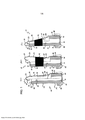
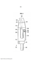
As figuras 1a a 1c são vistas seccionadas longitudinais de uma primeira modalidade de um dispositivo de segurança de agulha da presente invenção (a) em um estado desviado, (b) em um estado abaixado, e (c) em um estado relaxado sem um anel de tensão;Figures 1a to 1c are longitudinal sectional views of a first embodiment of a needle safety device of the present invention (a) in a deflected state, (b) in a lowered state, and (c) in a relaxed state without a ring of tension;
As figuras 2a e 2b são vistas em perspectiva de uma parte principal do dispositivo de segurança de agulha da reivindicação 1;Figures 2a and 2b are a perspective view of a main part of the needle safety device of claim 1;
As figuras 3a e 3b são vistas em perspectiva de um grampo de aço do dispositivo de segurança de agulha da figura 1;Figures 3a and 3b are a perspective view of a steel clip of the needle safety device of Figure 1;
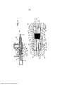
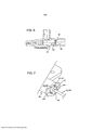
As figuras 4a e 4b são (a) uma vista em seção longitudinal do dispositivo de segurança de agulha da figura 1 como parte de um aparelho de cateter intravenoso, e (b) uma ampliação de uma porção da figura 4a;Figures 4a and 4b are (a) a longitudinal sectional view of the needle safety device of figure 1 as part of an intravenous catheter apparatus, and (b) an enlargement of a portion of figure 4a;
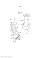
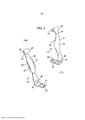
A figura 5 é uma vista lateral de uma segunda modalidade de um dispositivo de segurança de agulha de acordo com a presente invenção;Figure 5 is a side view of a second embodiment of a needle safety device according to the present invention;
A figura 6 é uma vista em seção longitudinal de uma modalidade alternativa de um alojamento de um aparelho de cateter intravenoso de acordo com a presente invenção; eFigure 6 is a longitudinal sectional view of an alternative embodiment of an intravenous catheter apparatus housing according to the present invention; and
A figura 7 é uma vista em perspectiva de uma porção de extremidade proximal de um alojamento de um aparelho de cateter intravenoso da presente invenção com um dispositivo de segurança de agulha parcialmente inserido no mesmo.Figure 7 is a perspective view of a proximal end portion of a housing for an intravenous catheter apparatus of the present invention with a needle safety device partially inserted therein.
A figura 1 mostra uma primeira modalidade de um dispositivo de segurança de agulha 10 da presente invenção. O dispositivo de segurança de agulha 10 compreende uma parte principal 12, um grampo 14 e um anel de tensão 16.Figure 1 shows a first embodiment of a
A parte principal 12 é produzida a partir de um material plástico e compreende uma porção de base 18 e uma porção alongada 20 que forma a primeira mandíbula. A porção de base 18 é de formato substancialmente cilíndrico que define uma direção axial 22, e é dotada de um orifício 24 que se estende através da mesma na direção axial 22 para receber uma agulha 26 (figura 4).The
A porção alongada 20 é de formato semicilíndrico e se estende a partir da porção de base 18 na direção axial 22. A porção alongada 20 é dotada de uma ranhura 28 formada em seu lado plano 29, o qual se estende na direção axial 22 ao longo de todo o comprimento da porção alongada 20 e forma uma extensão do orifício 24 na porção de base 18. Enquanto o orifício 24 é dotado de uma seção transversal em geral circular que é adaptada ao perfil externo da agulha 26, a ranhura 28 é dotada de uma seção transversal em geral semicircular.The
Na região da extremidade distai ou livre 30 da porção alongada 20, isto é, a extremidade da porção alongada 20 oposta a partir da porção de base 18, a porção alongada 20 é dotada de um diâmetro aumentado resultando em uma protuberância meio anular 32 que se estende para fora a partir do lado plano 29 da porção alongada 20. A protuberância 32 opera como uma protuberância de travamento, como será explicado em mais detalhes em relação com a figura 4.In the region of the distal or
O grampo 14 é formado a partir de uma tira de folha de metal dotada de propriedades similares à mola, tal como aço ou similar. O grampo 14 forma a segunda mandíbula e compreende uma seção de base 34 e uma seção flexível 36. A seção de base 34 inclui uma parte de seção axial 38 e uma parte de seção radial 40. A mesma é adaptada para engatar com a porção de base 18 da parte principal 12 de modo que a parte de seção axial 18 se encontra contra a superfície externa 42 da porção de base 18 enquanto a parte de seção radial 40 se encontra contra a face de extremidade proximal ou traseira 44 da porção de base 18, quando o grampo 14 é fixado à parte principal 12. De modo a garantir a posição correta da parte principal 12 e o grampo 14, a porção de base 18 é proporcionada com um guia 46 para o grampo 14, que compreende porções de superfície plana 48, 50 na superfície externa 42 e a face de extremidade 44, respectivamente, assim como paredes laterais 52 que definem um canal para o grampo 14.The
O grampo 14 é fixado à parte principal 12 por meio de uma conexão de vedação a calor. Para este fim, a parte principal 12 inicialmente é dotada de um pilar ou pino 54 formado na face de extremidade proximal 44 e que se estende em geral na direção axial 22. O grampo 14 é dotado de uma abertura correspondente 56 formada em sua parte de seção radial 40 para receber o pilar ou pino 54 quando o grampo 14 é montado na parte principal 12. Uma vez que o grampo 14 tenha sido trazido para a sua posição correta com relação à parte principal 12, o pilar ou pino 54 que se estende através da abertura 56 do grampo 14 é deformado por calor e/ou pressão de modo a aumentar o diâmetro do pilar ou pino 54. Ao tornar o diâmetro do pilar ou pino 54 maior do que o diâmetro da abertura 56, o grampo 14 é fixado com segurança na parte principal 12.The
A seção de base 34 do grampo 14 passa para dentro da seção flexível 36 por meio de uma dobra em forma de degrau da tira de folha de metal. A seção flexível 36 inclui uma parte de seção retilínea 58 que é reforçada por duas porções de asa alongadas 60 as quais se estendem em ambos os lados da parte de seção retilínea 58 e são dobradas para dentro, isto é em direção da primeira mandíbula, por um ângulo de substancialmente 90°. Em um estado relaxado do grampo 14 montado na parte principal 12 (figura 1c), a parte de seção retilínea 58 não exatamente se estende na direção axial 22, mas é relativamente dobrada em direção da porção alongada 20 da parte principal 12.The
Na região de sua extremidade distal, a parte de seção retilínea 58 passa para dentro da parte de seção de cabeça 62 que se estende adiante da extremidade livre 30 da porção alongada 20 da parte principal 12. A parte de seção de cabeça 62 é dotada de um formato em geral em forma de V com o pico do V apontando na direção axial 22 e a porção de perna livre 63 do V se estendendo em direção da porção alongada 20.In the region of its distal end, the
Na região de passagem a partir da parte de seção retilínea 58 para a parte de seção de cabeça 62, a tira de folha de metal do grampo 14 é dobrada para formar a protuberância 64 que se estende para fora, isto é, para fora a partir da porção alongada 20. A referida protuberância 64 funciona como uma protuberância de travamento como será explicado em mais detalhes em relação à figura 4.In the passage region from the
O anel de tensão 16 circunda a porção alongada 20 da parte principal 12 e a parte de seção retilínea 58 do grampo 14 na região das porções de asa alongadas 60. O anel de tensão 16 é produzido a partir de um material dotado de propriedades elásticas, por exemplo, borracha. O anel de tensão 16 é configurado de modo que a seção flexível 36 do grampo 14 é desviada contra uma força de restauração do anel de tensão 16, quando a agulha 26 se estende inteiramente através do dispositivo de segurança de agulha 10. A referida situação é chamada de estado desviado do dispositivo de segurança de agulha 10 e é mostrada nas figuras 1a e 4b, em que a agulha 26 foi omitida na figura 1a.The
Quando a agulha 26 não se estende inteiramente através do dispositivo de segurança de agulha 10 ou quando não há agulha 26 alguma, a seção flexível 36 do grampo 14 é arrastada em direção da porção alongada 20 da parte principal 12 pelo anel de tensão 16, como é mostrado na figura 1b. Na referida situação, que é referida como o estado abaixado do dispositivo de segurança de agulha 10, a parte de seção de cabeça 62 do grampo 14 se sobrepõe ao ou se estende sobre pelo menos uma porção da face de extremidade distai 66 da porção alongada 20, deste modo evitando que a ponta da agulha 26 se saliente para fora do dispositivo de segurança de agulha 10 na extremidade distai da mesma.When the needle 26 does not extend entirely through the
A figura 4a mostra um aparelho de cateter intravenoso 68 e o dispositivo de segurança de agulha 10 acima descrito montado no mesmo.Figure 4a shows an intravenous catheter device 68 and the
O aparelho de cateter intravenoso 68 compreende um alojamento 70, por exemplo, um alojamento de asa, dotado de um cateter 72 que se estende a partir da extremidade distal do mesmo. O alojamento 70 define uma câmara 74.The intravenous catheter apparatus 68 comprises a
A agulha 26 se estende através da câmara 74 e através do cateter 72. Na região de sua extremidade proximal, um cubo de agulha 76 é fixado à agulha 26.Needle 26 extends through
No estado inicial do aparelho de cateter intravenoso 68, isto é, antes de seu uso, o dispositivo de segurança de agulha 10 é deslizavelmente arranjado na agulha 26 e inserido na câmara 74 a partir da extremidade proximal do alojamento 70.In the initial state of the intravenous catheter apparatus 68, that is, before use, the
Em virtude da agulha 26 que se estende inteiramente através do dispositivo de segurança de agulha 10, a seção flexível 36 do grampo 14 é desviada para fora, isto é, para fora a partir da porção alongada 20 da parte principal 12 e em direção do lado de dentro do alojamento 70, com a parte de seção de cabeça 62 sendo suportada na agulha 26. Em virtude de sua deflexão a seção flexível 36 e, em particular, sua protuberância de travamento 64 toca contra a superfície interna do alojamento 70. Ao mesmo tempo, a protuberância de travamento 32 da porção alongada 20 da parte principal 12 está em contato com a superfície interna do alojamento 70.By virtue of the needle 26 which extends entirely through the
Como pode ser visto a partir da figura 4b, uma protuberância de travamento anular 78 que se estende pra dentro da câmara 74 é formada no lado de dentro do alojamento 70. Adicionalmente, uma depressão de travamento anular 80 é formada adjacente à protuberância de travamento anular 78 no lado distai da mesma.As can be seen from figure 4b, an
A posição axial da protuberância de travamento anular 78 e da depressão de travamento 80 é de modo que a protuberância de travamento 64 do grampo 14 é recebida na depressão de travamento 80, e não só a protuberância de travamento 64 do grampo 14 mas também a protuberância de travamento 32 da parte principal 12 engatam atrás da protuberância de travamento anular 78 do alojamento 70, quando o dispositivo de segurança de agulha 10 está completamente inserido no alojamento 70 e a agulha 26 se estende inteiramente através do dispositivo de segurança de agulha 10. Deste modo o dispositivo de segurança de agulha 10 é evitado de se mover axialmente em direção da extremidade proximal do alojamento 70 desde que a agulha 26 se estenda inteiramente através do dispositivo de segurança de agulha 10, mesmo se a agulha 26 é retraída a partir do cateter 72, por exemplo, com a retirada a partir de um paciente, e deste modo movida com relação ao dispositivo de segurança de agulha 10 (à esquerda na figura 4).The axial position of the
Tão logo a ponta da agulha 26 passa a parte de seção de cabeça 62 do grampo 14, a seção flexível 36 não é mais suportada pela agulha 26. Consequentemente, a seção flexível 36 do grampo 14 é arrastada em direção da porção alongada 20 em virtude da força de restauração do anel de tensão 16, deste modo trazendo o dispositivo de segurança de agulha 10 para o seu estado abaixado. No estado abaixado, as protuberâncias de travamento 32, 64 do dispositivo de segurança de agulha 10 são desengatados a partir da depressão de travamento 80 e da protuberância de travamento 78 do alojamento 70, o que permite com que o dispositivo de segurança de agulha 10 seja movido para fora do alojamento 70 junto com a agulha 26. Uma vez que a ponta da agulha 26 sai do alojamento 70, a ponta da agulha é guardada pelo dispositivo de segurança de agulha 10, e a agulha 26 pode ser descartada com segurança.As soon as the tip of the needle 26 passes the
Com referência à figura 5, uma segunda modalidade do dispositivo de segurança de agulha 110 da presente invenção será agora descrita.With reference to figure 5, a second embodiment of the
Similar ao dispositivo de segurança de agulha 10 acima mencionado, o dispositivo de segurança de agulha 110 mostrado na figura 5 compreende a parte principal 112 que pode ser produzida a partir de um material plástico e que inclui uma porção de base 118. A porção de base 118 é em geral de formato cilíndrico e é dotada de um orifício que se estende em uma direção axial para receber uma agulha 126.Similar to the aforementioned
A parte principal 112 adicionalmente compreende uma primeira porção alongada 120 que se estende a partir da porção de base 118 em geral na direção axial e que é também referida como a primeira mandíbula. A primeira porção alongada 120 é dotada de uma parte de seção transversal circular.The
A parte principal 112 adicionalmente compreende uma segunda porção alongada 134 que se estende a partir da porção de base 118 na dire- ção axial e arranjada em oposição a partir da primeira porção alongada 120. A segunda porção alongada 134 também é dotada de uma parte de seção transversal circular. O comprimento da segunda porção alongada 134 é aproximadamente metade do comprimento da primeira porção alongada 120.The
A primeira porção alongada 120 e a segunda porção alongada 134 ambas são dotadas de superfícies planas 129 voltadas uma em direção à outra e que definem um espaço para a agulha 126 se estender entre as porções alongadas 120, 134.The first
A parte principal 112 adicionalmente compreende a porção flexível 136 que é pivotavelmente montada na segunda porção alongada 134 na região de extremidade distai ou livre da mesma. A segunda porção alongada 134 e a porção flexível 136 juntas formam a segunda mandíbula do dispositivo de segurança de agulha 110.The
Na modalidade mostrada na figura 5, a porção flexível 136 é montada na segunda porção alongada 134 por meio de uma articulação compreendendo dois pivôs 138 formados na porção flexível 136, que se estende perpendicularmente à direção axial e que são pivotados em orifícios correspondentes 140 proporcionados na segunda porção alongada 134.In the embodiment shown in figure 5, the
Como mostrada na figura 5, a porção flexível 136 e a segunda porção alongada 134 são produzidas a partir de duas partes separadas, em que a porção flexível 136 preferivelmente também compreende um material plástico. Entretanto, será entendido que a porção flexível 136 e a segunda porção alongada 134 podem também ser formadas como uma parte integral, em cujo caso a articulação que conecta a porção flexível 136 e a segunda porção alongada 134 pode ser uma articulação de filme.As shown in figure 5, the
Em virtude da porção flexível 136 ser montada na segunda porção alongada 134 por meio de uma articulação, a porção flexível 136 pode ser desviada para fora, isto é, para fora a partir da primeira porção alongada 120, sobre um eixo perpendicular à direção axial.Because the
Na região de sua extremidade distai ou livre, a porção flexível 136 compreende uma seção de extremidade 162, que se estende perpendicularmente à seção principal da porção flexível 136 em direção da primeira porção alongada 120. O comprimento da seção de extremidade 162 é de modo que a mesma passa através de pelo menos a parte da extremidade livre 130 da primeira porção alongada 120, quando a porção flexível 136 está na posição colabada, deste modo tornando impossível para a agulha 126 se salientar para fora do dispositivo de segurança de agulha 110 na extremidade distai da mesma.In the region of its distal or free end, the
O dispositivo de segurança de agulha 110 adicionalmente compreende um anel de tensão 116 envolvendo a primeira porção alongada 120 e a porção flexível 136. O anel de tensão 116 é produzido a partir de um material elástico e configurado de modo que a porção flexível 136 pode ser desviada para fora contra uma força de restauração do anel de tensão 116 a partir da posição colabada (mostrada na figura 5) para a posição desviada.The
De modo a manter a posição correta do anel de tensão 116, uma seção da primeira porção alongada 120 oposta a partir da porção flexível 136 e a porção flexível 136 juntas definem um contorno externo das primeira e segunda mandíbulas, que se inclinam em direção da extremidade distal do dispositivo de segurança de agulha 110 quando a porção flexível 136 está na posição colabada.In order to maintain the correct position of the
Na região de sua extremidade livre 130, a protuberância 132 é formada na primeira porção alongada 120, que se estende para fora, isto é, para fora a partir da porção flexível 136. De modo similar, a protuberância 164 é formada na porção flexível 136, que se estende para fora, isto é, para fora a partir da primeira porção alongada 120. A protuberância 132 da primeira porção alongada 120 e a protuberância 164 da porção flexível 136 são formadas aproximadamente na mesma posição axial.In the region of its
As protuberâncias 132, 164 não só evitam que o anel de tensão 116 deslize para fora das mandíbulas, mas também operam como protuberâncias de travamento para travar o dispositivo de segurança de agulha 110 dentro do alojamento 70, por exemplo, de um aparelho de cateter intravenoso 68 como foi explicado em relação com a figura 4, quando a agulha 126 se estende inteiramente através do dispositivo de segurança de agulha 110 e a seção de extremidade angulada 162 da porção flexível 136 é suportada na agulha 126 deste modo desviando a porção flexível 136 para fora.The
Em conexão com a figura 4, a depressão de travamento 80 do aparelho de cateter intravenoso 68 proporcionado para receber a protuberâncias de travamento 32, 64 do dispositivo de segurança de agulha 10 foi descrita para ser de formato anular, isto é, para se estender ao longo de toda a periferia interna do alojamento 70 do aparelho de cateter intravenoso 68.In connection with figure 4, the locking
Entretanto, será entendido que a depressão de travamento 80 não precisa ser de formato completamente anular. Em vez disso, a protuberância de travamento 80 pode também ser de formato parcialmente anular.However, it will be understood that the locking
A figura 6 mostra uma modalidade alternativa de um alojamento 70 de um aparelho de cateter intravenoso 68, na qual a depressão de travamento 80 se estende ao longo de menos do que a metade da periferia interna do alojamento 70, isto é, a depressão de travamento 80 pode ser referida como menos do que semianular. Em geral, o comprimento da depressão de travamento 80 pode ser qualquer coisa na faixa a partir de cerca de um quarto anular a completamente anular.Figure 6 shows an alternative embodiment of a
Deve ser observado que no caso em que a depressão de travamento 80 não é uma depressão completamente anular, mas em vez disso de formato parcialmente anular, o dispositivo de segurança de agulha 10 precisa ser inserido no alojamento 70 do aparelho de cateter intravenoso 68 em uma posição rotacional predefinida, de modo a garantir que a protuberância de travamento 64 do grampo 14 ou da porção flexível 136 seja recebida com segurança na depressão de travamento 80.It should be noted that in the case where the locking
De modo a garantir que o dispositivo de segurança de agulha 10 possa ser inserido no alojamento 70 do aparelho de cateter intravenoso 68 apenas na posição rotacional correta, a porção de base 18, 118 do dispositivo de segurança de agulha 10, 110 pode ser dotada de um perfil externo não cilíndrico adaptado para corresponder com uma seção transversal interna correspondentemente não circular do alojamento 70, como pode ser visto na figura 7. Especificamente, a porção de base 18, 118 do dispositivo de segurança de agulha 10, 110 é proporcionado com uma ampliação de parte cilíndrica resultando em superfícies planas 166 formadas em lados opostos da porção de base 18, 118. Ombros opostos entre si são formados no lado de dentro do alojamento 70, que é dotado de superfícies planas correspondentes, de modo que o dispositivo de segurança de agulha 10, 110 pode apenas ser inserido no alojamento 70 quando as superfícies planas 166 da porção de base 18, 118 são alinhadas com as superfícies planas dos ombros do alojamento 70.In order to ensure that the
Será entendido que, outros formatos não cilíndricos do dispositivo de segurança de agulha 10, 110 e seções transversais internas não circulares do alojamento 70 podem ser usados para garantir a correta inserção do dispositivo de segurança de agulha 10, 110 dentro do alojamento 70, como, por exemplo, formatos ovais ou poligonais.It will be understood that other non-cylindrical shapes of the
10 dispositivo de segurança de agulha 12 parte principal 14 grampo 16 anel de tensão 18 porção de base 20 porção alongada 22 direção axial 24 orifício 26 agulha 28 ranhura 29 lado plano 30 extremidade livre 32 protuberância 34 seção de base 36 seção flexível 38 parte de seção axial 40 parte de seção radial 42 superfície externa 44 face de extremidade 46 guia 48 porção de superfície plana 50 porção de superfície plana 52 parede lateral 54 pilar/pino 56 abertura 58 parte de seção retilínea 60 asa alongada 62 parte de seção de cabeça 63 porção de perna livre 64 protuberância 66 face de extremidade 68 aparelho de cateter intravenoso 70 alojamento 72 cateter 74 câmara 76 cubo de agulha 78 protuberância de travamento anular 80 depressão de travamento 110 dispositivo de segurança de agulha 112 parte principal 116 anel de tensão 118 porção de base 120 primeira porção alongada 126 agulha 129 superfície plana 130 extremidade livre 132 protuberância de travamento 134 segunda porção alongada 136 porção flexível 138 pivô 140 orifício 162 seção de extremidade 164 protuberância de travamento 166 superfície plana10
Claims (12)
Applications Claiming Priority (3)
| Application Number | Priority Date | Filing Date | Title |
|---|---|---|---|
| IN674DE2008 | 2008-03-17 | ||
| IN674/DEL/2008 | 2008-03-17 | ||
| PCT/IN2009/000124 WO2009116080A2 (en) | 2008-03-17 | 2009-02-25 | Needle safety device |
Publications (3)
| Publication Number | Publication Date |
|---|---|
| BRPI0909094A2 BRPI0909094A2 (en) | 2015-08-11 |
| BRPI0909094B1 true BRPI0909094B1 (en) | 2020-10-20 |
| BRPI0909094B8 BRPI0909094B8 (en) | 2021-06-22 |
Family
ID=41091340
Family Applications (1)
| Application Number | Title | Priority Date | Filing Date |
|---|---|---|---|
| BRPI0909094A BRPI0909094B8 (en) | 2008-03-17 | 2009-02-25 | needle safety device and intravenous catheter apparatus |
Country Status (16)
| Country | Link |
|---|---|
| US (1) | US8784386B2 (en) |
| EP (4) | EP2417997B1 (en) |
| JP (1) | JP5743882B2 (en) |
| KR (1) | KR101332743B1 (en) |
| CN (2) | CN104338206B (en) |
| AU (1) | AU2009227517B2 (en) |
| BR (1) | BRPI0909094B8 (en) |
| CO (1) | CO6310966A2 (en) |
| EA (1) | EA018449B1 (en) |
| ES (3) | ES2432243T3 (en) |
| IL (1) | IL208161A (en) |
| MX (1) | MX2010010032A (en) |
| MY (1) | MY169767A (en) |
| UA (1) | UA100143C2 (en) |
| WO (1) | WO2009116080A2 (en) |
| ZA (1) | ZA201006684B (en) |
Families Citing this family (21)
| Publication number | Priority date | Publication date | Assignee | Title |
|---|---|---|---|---|
| JP4994775B2 (en) | 2006-10-12 | 2012-08-08 | 日本コヴィディエン株式会社 | Needle point protector |
| ES2351233T5 (en) * | 2007-07-17 | 2014-06-16 | Poly Medicure Ltd. | Needle safety device |
| UA110794C2 (en) * | 2010-05-05 | 2016-02-25 | Полі Медікьюе Лімітед | Protective device for medical needles instruments and node iv catheter comprising said needle protective device |
| WO2012014017A1 (en) * | 2010-07-30 | 2012-02-02 | Poly Medicure Limited | Catheter introducer |
| PL2600925T3 (en) | 2010-08-05 | 2021-12-06 | B. Braun Melsungen Ag | Needle safety device and assembly |
| WO2012038899A1 (en) * | 2010-09-21 | 2012-03-29 | Poly Medicure Limited | Needle tip guard for intravenous catheter assembly |
| US9238104B2 (en) | 2011-02-28 | 2016-01-19 | Injectimed, Inc. | Needle guard |
| US8764711B2 (en) | 2011-02-28 | 2014-07-01 | Injectimed, Inc. | Needle guard |
| EP2517751B8 (en) | 2011-04-27 | 2018-02-28 | Kpr U.S., Llc | Safety IV catheter assemblies |
| WO2013014638A1 (en) | 2011-07-26 | 2013-01-31 | Poly Medicure Limited | Needle tip protector assembly for safety iv catheter assembly |
| WO2013048975A1 (en) | 2011-09-26 | 2013-04-04 | Covidien Lp | Safety catheter |
| EP2760521B1 (en) | 2011-09-26 | 2016-01-06 | Covidien LP | Safety iv catheter and needle assembly |
| US8834422B2 (en) | 2011-10-14 | 2014-09-16 | Covidien Lp | Vascular access assembly and safety device |
| EP4233970A3 (en) | 2011-11-08 | 2023-10-11 | Poly Medicure Limited | Intravenous catheter apparatus |
| IN2012DE00486A (en) * | 2012-02-21 | 2015-06-05 | Poly Medicure Ltd | |
| EP2941289B1 (en) * | 2013-01-03 | 2019-09-25 | Vigmed AB | Spring clip needle guard |
| CN106029153A (en) * | 2013-12-20 | 2016-10-12 | B.布劳恩梅尔松根股份公司 | Safety needle assemblies and related methods |
| WO2016163939A1 (en) * | 2015-04-09 | 2016-10-13 | Vigmed Ab | Needle tip shielding device and catheter hub therefore |
| US11896788B2 (en) * | 2016-06-06 | 2024-02-13 | Medline Industries, Lp | Needle safety clip, systems and methods |
| US10946176B2 (en) * | 2017-04-06 | 2021-03-16 | Becton, Dickinson And Company | Intravenous catheter assembly with safety clip |
| US11344704B2 (en) * | 2019-07-11 | 2022-05-31 | Becton, Dickinson And Company | Catheter system facilitating reduced drag force |
Family Cites Families (34)
| Publication number | Priority date | Publication date | Assignee | Title |
|---|---|---|---|---|
| US4832019A (en) * | 1988-03-16 | 1989-05-23 | Burton Weinstein | Endotracheal tube holder |
| US4929241A (en) * | 1988-08-05 | 1990-05-29 | Kulli John C | Medical needle puncture guard |
| US5172700A (en) * | 1989-01-31 | 1992-12-22 | C. R. Bard, Inc. | Disposable biopsy forceps |
| US4964866A (en) * | 1989-11-22 | 1990-10-23 | Becton, Dickinson And Company | Needle sheath assembly |
| US5558651A (en) * | 1990-04-20 | 1996-09-24 | Becton Dickinson And Company | Apparatus and method for a needle tip cover |
| US5215528C1 (en) | 1992-02-07 | 2001-09-11 | Becton Dickinson Co | Catheter introducer assembly including needle tip shield |
| US5300045A (en) * | 1993-04-14 | 1994-04-05 | Plassche Jr Walter M | Interventional needle having an automatically capping stylet |
| US5344408A (en) * | 1993-08-06 | 1994-09-06 | Becton, Dickinson And Company | Break-away safety shield for needle cannula |
| JP2584597B2 (en) | 1993-09-29 | 1997-02-26 | ベクトン・ディッキンソン・アンド・カンパニー | Catheter introduction device with blood seal |
| EP2319556B1 (en) | 1996-02-27 | 2013-04-24 | B. Braun Melsungen AG | Needle tip guard for hypodermic needles |
| DE20104539U1 (en) | 2000-08-14 | 2001-12-20 | Braun Melsungen Ag | Intravenous catheter device |
| US6616630B1 (en) * | 1997-08-20 | 2003-09-09 | B. Braun Melsungen A.G. | Spring clip safety IV catheter |
| US6117108A (en) | 1997-08-20 | 2000-09-12 | Braun Melsungen Ag | Spring clip safety IV catheter |
| US20020173752A1 (en) * | 2000-02-16 | 2002-11-21 | Polzin U1F | Method for reconstituting an injection liquid and an injection appliance for carrying out such a method |
| US6855130B2 (en) | 2000-03-07 | 2005-02-15 | Becton, Dickinson And Company | Passive safety device for needle of IV infusion or blood collection set |
| US6537259B1 (en) * | 2000-03-07 | 2003-03-25 | Becton, Dickinson And Company | Passive safety device |
| US6902546B2 (en) * | 2001-03-15 | 2005-06-07 | Specialized Health Products, Inc. | Safety shield for medical needles |
| US7179244B2 (en) * | 2001-03-15 | 2007-02-20 | Specialized Health Products, Inc. | Resettable safety shield for medical needles |
| ITBO20010497A1 (en) * | 2001-07-31 | 2003-01-31 | Delta Med S R L | PROTECTION DEVICE FOR NEEDLE-CANNULA |
| PT1610854E (en) | 2003-04-08 | 2008-10-02 | Medex Inc | Safety needle and catheter assembly |
| DE20315872U1 (en) | 2003-10-15 | 2004-02-12 | B. Braun Melsungen Ag | Protective cover for injection or infusion needles, comprises a needle holder, a protective element that is pushed onto the shaft, and locating elements |
| DE20316804U1 (en) | 2003-10-31 | 2005-03-10 | B. Braun Melsungen Ag | catheter device |
| KR20060130653A (en) * | 2004-02-13 | 2006-12-19 | 스미스 메디칼 에이에스디, 인크. | Needle tip protector |
| US20050251092A1 (en) | 2004-05-10 | 2005-11-10 | Becton, Dickinson And Company | Needle assembly with tether |
| US7112191B2 (en) * | 2004-06-15 | 2006-09-26 | Neha Daga | Needle safety device for an intravenous catheter apparatus and method of use |
| US20060235520A1 (en) * | 2005-04-19 | 2006-10-19 | Pannu Yashdip S | Spinal implant apparatus, method and system |
| US8251950B2 (en) | 2005-08-08 | 2012-08-28 | Smiths Medical Asd, Inc. | Needle guard clip with heel |
| US20070038187A1 (en) * | 2005-08-08 | 2007-02-15 | Albert Sean J | Needle guard mechanism with anti-rotation feature |
| JP4921779B2 (en) * | 2005-11-28 | 2012-04-25 | 日本コヴィディエン株式会社 | Indwelling needle |
| US8382718B2 (en) * | 2006-07-31 | 2013-02-26 | B. Braun Melsungen Ag | Needle assembly and components thereof |
| JP4848989B2 (en) * | 2007-03-27 | 2011-12-28 | ニプロ株式会社 | Protector |
| DE202007009977U1 (en) | 2007-07-17 | 2007-11-08 | Poly Medicure Ltd. | Needle securing device for an intravenous catheter device |
| ES2351233T5 (en) * | 2007-07-17 | 2014-06-16 | Poly Medicure Ltd. | Needle safety device |
| ES2388246T3 (en) * | 2008-05-28 | 2012-10-11 | Poly Medicure Ltd. | Catheter introducer |
-
2009
- 2009-02-25 ES ES09723050T patent/ES2432243T3/en active Active
- 2009-02-25 ES ES11008553T patent/ES2436244T3/en active Active
- 2009-02-25 EA EA201071093A patent/EA018449B1/en not_active IP Right Cessation
- 2009-02-25 EP EP20110008552 patent/EP2417997B1/en active Active
- 2009-02-25 MY MYPI2010004366A patent/MY169767A/en unknown
- 2009-02-25 CN CN201410503544.XA patent/CN104338206B/en not_active Expired - Fee Related
- 2009-02-25 EP EP11008553.7A patent/EP2412398B1/en active Active
- 2009-02-25 WO PCT/IN2009/000124 patent/WO2009116080A2/en active Application Filing
- 2009-02-25 EP EP09723050.2A patent/EP2249904B1/en active Active
- 2009-02-25 ES ES11008552.9T patent/ES2545500T3/en active Active
- 2009-02-25 US US12/922,838 patent/US8784386B2/en active Active
- 2009-02-25 KR KR1020107023003A patent/KR101332743B1/en active IP Right Grant
- 2009-02-25 JP JP2011500350A patent/JP5743882B2/en active Active
- 2009-02-25 BR BRPI0909094A patent/BRPI0909094B8/en active IP Right Grant
- 2009-02-25 AU AU2009227517A patent/AU2009227517B2/en active Active
- 2009-02-25 UA UAA201012184A patent/UA100143C2/en unknown
- 2009-02-25 MX MX2010010032A patent/MX2010010032A/en active IP Right Grant
- 2009-02-25 EP EP14155772.8A patent/EP2735331A3/en not_active Withdrawn
- 2009-02-25 CN CN200980117948.2A patent/CN102083488B/en not_active Expired - Fee Related
-
2010
- 2010-09-15 IL IL208161A patent/IL208161A/en active IP Right Grant
- 2010-09-17 ZA ZA2010/06684A patent/ZA201006684B/en unknown
- 2010-10-15 CO CO10128311A patent/CO6310966A2/en active IP Right Grant
Also Published As
Similar Documents
| Publication | Publication Date | Title |
|---|---|---|
| BRPI0909094B1 (en) | needle safety device and intravenous catheter device | |
| ES2909485T3 (en) | Double Bore Cannula Needle Devices and Related Methods | |
| JP3609760B2 (en) | Venous catheter device | |
| KR101893762B1 (en) | Catheter assembly with improved safety means | |
| ES2549059T3 (en) | Needle tip spring guard | |
| ES2390025T3 (en) | Catheter introducer | |
| ES2391445T3 (en) | Needle | |
| RU2645600C1 (en) | Needle-protection device for medical instruments | |
| BR112012026334B1 (en) | CATHETER APPLIANCE AND CATHETER INTRODUCER | |
| JP2004505684A (en) | Syringe needle protector | |
| BR112013002767B1 (en) | NEEDLE ASSEMBLY AND METHOD FOR ASSEMBLING A NEEDLE ASSEMBLY | |
| BR122013013980A2 (en) | CATHETER SET | |
| ITMI20070296U1 (en) | SAFETY DEVICE OF THE NEEDLE FOR ENDOVOUS CATHETER | |
| CN103200986A (en) | Needle tip guard for intravenous catheter assembly | |
| JP2017099884A (en) | Needle device having bistable structure and relevant method | |
| BRPI0618747A2 (en) | quick coupling for pipes | |
| WO2014166353A1 (en) | Butterfly-type needle assembly and butterfly-type needle protective sleeve | |
| BR112020004830A2 (en) | syringe with locking mechanism | |
| JP2002253670A (en) | Needle for syringe with safety device |
Legal Events
| Date | Code | Title | Description |
|---|---|---|---|
| B06F | Objections, documents and/or translations needed after an examination request according [chapter 6.6 patent gazette] | ||
| B06T | Formal requirements before examination [chapter 6.20 patent gazette] | ||
| B07A | Application suspended after technical examination (opinion) [chapter 7.1 patent gazette] | ||
| B09A | Decision: intention to grant [chapter 9.1 patent gazette] | ||
| B16A | Patent or certificate of addition of invention granted [chapter 16.1 patent gazette] |
Free format text: PRAZO DE VALIDADE: 10 (DEZ) ANOS CONTADOS A PARTIR DE 20/10/2020, OBSERVADAS AS CONDICOES LEGAIS. |
|
| B16C | Correction of notification of the grant [chapter 16.3 patent gazette] |
Free format text: PRAZO DE VALIDADE: 20 (VINTE) ANOS CONTADOS A PARTIR DE 25/02/2009, OBSERVADAS AS CONDICOES LEGAIS. PATENTE CONCEDIDA CONFORME ADI 5.529/DF, QUE DETERMINA A ALTERACAO DO PRAZO DE CONCESSAO |