BRPI0907488B1 - APPLIANCE FOR COOLING A CRYOGENIC HEAT EXCHANGER, METHOD FOR COOLING A CRYOGENIC HEAT EXCHANGER, AND METHODS FOR LIQUEFACING A HYDROCARBON CHAIN - Google Patents
APPLIANCE FOR COOLING A CRYOGENIC HEAT EXCHANGER, METHOD FOR COOLING A CRYOGENIC HEAT EXCHANGER, AND METHODS FOR LIQUEFACING A HYDROCARBON CHAIN Download PDFInfo
- Publication number
- BRPI0907488B1 BRPI0907488B1 BRPI0907488-0A BRPI0907488A BRPI0907488B1 BR PI0907488 B1 BRPI0907488 B1 BR PI0907488B1 BR PI0907488 A BRPI0907488 A BR PI0907488A BR PI0907488 B1 BRPI0907488 B1 BR PI0907488B1
- Authority
- BR
- Brazil
- Prior art keywords
- refrigerant
- heat exchanger
- cryogenic heat
- valve
- module
- Prior art date
Links
- 150000002430 hydrocarbons Chemical group 0.000 title claims abstract description 101
- 238000000034 method Methods 0.000 title claims abstract description 59
- 238000001816 cooling Methods 0.000 claims abstract description 133
- 229930195733 hydrocarbon Natural products 0.000 claims abstract description 100
- 239000004215 Carbon black (E152) Substances 0.000 claims abstract description 97
- 238000004891 communication Methods 0.000 claims abstract description 37
- 239000003507 refrigerant Substances 0.000 claims description 248
- VNWKTOKETHGBQD-UHFFFAOYSA-N methane Chemical compound C VNWKTOKETHGBQD-UHFFFAOYSA-N 0.000 claims description 82
- 239000007789 gas Substances 0.000 claims description 35
- 239000007788 liquid Substances 0.000 claims description 34
- 230000008859 change Effects 0.000 claims description 26
- 238000004064 recycling Methods 0.000 claims description 26
- 230000004913 activation Effects 0.000 claims description 25
- 239000003345 natural gas Substances 0.000 claims description 25
- 238000011144 upstream manufacturing Methods 0.000 claims description 11
- 238000001704 evaporation Methods 0.000 claims description 7
- 230000009471 action Effects 0.000 claims description 6
- 238000007599 discharging Methods 0.000 claims 2
- 230000008569 process Effects 0.000 abstract description 22
- 238000004590 computer program Methods 0.000 abstract description 10
- 230000003213 activating effect Effects 0.000 abstract 1
- ATUOYWHBWRKTHZ-UHFFFAOYSA-N Propane Chemical compound CCC ATUOYWHBWRKTHZ-UHFFFAOYSA-N 0.000 description 32
- 238000012360 testing method Methods 0.000 description 18
- 239000001294 propane Substances 0.000 description 16
- 230000000694 effects Effects 0.000 description 12
- IJGRMHOSHXDMSA-UHFFFAOYSA-N Atomic nitrogen Chemical compound N#N IJGRMHOSHXDMSA-UHFFFAOYSA-N 0.000 description 10
- 230000006835 compression Effects 0.000 description 10
- 238000007906 compression Methods 0.000 description 10
- 238000009833 condensation Methods 0.000 description 10
- 230000005494 condensation Effects 0.000 description 10
- 239000000203 mixture Substances 0.000 description 10
- 238000002360 preparation method Methods 0.000 description 9
- 239000003949 liquefied natural gas Substances 0.000 description 8
- OFBQJSOFQDEBGM-UHFFFAOYSA-N n-pentane Natural products CCCCC OFBQJSOFQDEBGM-UHFFFAOYSA-N 0.000 description 7
- 238000005259 measurement Methods 0.000 description 6
- 238000004886 process control Methods 0.000 description 6
- 239000000047 product Substances 0.000 description 6
- 229910052757 nitrogen Inorganic materials 0.000 description 5
- 238000000746 purification Methods 0.000 description 5
- 238000010992 reflux Methods 0.000 description 5
- 238000003860 storage Methods 0.000 description 5
- OTMSDBZUPAUEDD-UHFFFAOYSA-N Ethane Chemical compound CC OTMSDBZUPAUEDD-UHFFFAOYSA-N 0.000 description 4
- 230000033228 biological regulation Effects 0.000 description 4
- 238000010586 diagram Methods 0.000 description 4
- 238000004519 manufacturing process Methods 0.000 description 4
- 239000001273 butane Substances 0.000 description 3
- 238000004422 calculation algorithm Methods 0.000 description 3
- 230000008020 evaporation Effects 0.000 description 3
- 238000000605 extraction Methods 0.000 description 3
- 239000012530 fluid Substances 0.000 description 3
- 238000012544 monitoring process Methods 0.000 description 3
- IJDNQMDRQITEOD-UHFFFAOYSA-N n-butane Chemical compound CCCC IJDNQMDRQITEOD-UHFFFAOYSA-N 0.000 description 3
- 238000005057 refrigeration Methods 0.000 description 3
- 239000002826 coolant Substances 0.000 description 2
- 238000005194 fractionation Methods 0.000 description 2
- 238000010348 incorporation Methods 0.000 description 2
- 238000012423 maintenance Methods 0.000 description 2
- 230000003134 recirculating effect Effects 0.000 description 2
- 230000004044 response Effects 0.000 description 2
- VGGSQFUCUMXWEO-UHFFFAOYSA-N Ethene Chemical compound C=C VGGSQFUCUMXWEO-UHFFFAOYSA-N 0.000 description 1
- 239000005977 Ethylene Substances 0.000 description 1
- -1 H2O Chemical class 0.000 description 1
- CDBYLPFSWZWCQE-UHFFFAOYSA-L Sodium Carbonate Chemical compound [Na+].[Na+].[O-]C([O-])=O CDBYLPFSWZWCQE-UHFFFAOYSA-L 0.000 description 1
- 206010000210 abortion Diseases 0.000 description 1
- 231100000176 abortion Toxicity 0.000 description 1
- 238000000137 annealing Methods 0.000 description 1
- 238000013459 approach Methods 0.000 description 1
- 150000004945 aromatic hydrocarbons Chemical class 0.000 description 1
- 238000009529 body temperature measurement Methods 0.000 description 1
- 238000004364 calculation method Methods 0.000 description 1
- 239000000470 constituent Substances 0.000 description 1
- 230000008602 contraction Effects 0.000 description 1
- 230000007423 decrease Effects 0.000 description 1
- 230000003111 delayed effect Effects 0.000 description 1
- 230000001419 dependent effect Effects 0.000 description 1
- 238000013461 design Methods 0.000 description 1
- 238000001514 detection method Methods 0.000 description 1
- 238000009826 distribution Methods 0.000 description 1
- 239000002737 fuel gas Substances 0.000 description 1
- 239000007792 gaseous phase Substances 0.000 description 1
- 238000009434 installation Methods 0.000 description 1
- 239000012263 liquid product Substances 0.000 description 1
- 238000012986 modification Methods 0.000 description 1
- 230000004048 modification Effects 0.000 description 1
- 238000005457 optimization Methods 0.000 description 1
- 238000002203 pretreatment Methods 0.000 description 1
- 238000012545 processing Methods 0.000 description 1
- QQONPFPTGQHPMA-UHFFFAOYSA-N propylene Natural products CC=C QQONPFPTGQHPMA-UHFFFAOYSA-N 0.000 description 1
- 125000004805 propylene group Chemical group [H]C([H])([H])C([H])([*:1])C([H])([H])[*:2] 0.000 description 1
- 238000012887 quadratic function Methods 0.000 description 1
- 150000003464 sulfur compounds Chemical class 0.000 description 1
- 238000010257 thawing Methods 0.000 description 1
- 238000012546 transfer Methods 0.000 description 1
- XLYOFNOQVPJJNP-UHFFFAOYSA-N water Substances O XLYOFNOQVPJJNP-UHFFFAOYSA-N 0.000 description 1
Images


Classifications
-
- F—MECHANICAL ENGINEERING; LIGHTING; HEATING; WEAPONS; BLASTING
- F25—REFRIGERATION OR COOLING; COMBINED HEATING AND REFRIGERATION SYSTEMS; HEAT PUMP SYSTEMS; MANUFACTURE OR STORAGE OF ICE; LIQUEFACTION SOLIDIFICATION OF GASES
- F25J—LIQUEFACTION, SOLIDIFICATION OR SEPARATION OF GASES OR GASEOUS OR LIQUEFIED GASEOUS MIXTURES BY PRESSURE AND COLD TREATMENT OR BY BRINGING THEM INTO THE SUPERCRITICAL STATE
- F25J1/00—Processes or apparatus for liquefying or solidifying gases or gaseous mixtures
- F25J1/02—Processes or apparatus for liquefying or solidifying gases or gaseous mixtures requiring the use of refrigeration, e.g. of helium or hydrogen ; Details and kind of the refrigeration system used; Integration with other units or processes; Controlling aspects of the process
- F25J1/0211—Processes or apparatus for liquefying or solidifying gases or gaseous mixtures requiring the use of refrigeration, e.g. of helium or hydrogen ; Details and kind of the refrigeration system used; Integration with other units or processes; Controlling aspects of the process using a multi-component refrigerant [MCR] fluid in a closed vapor compression cycle
- F25J1/0214—Processes or apparatus for liquefying or solidifying gases or gaseous mixtures requiring the use of refrigeration, e.g. of helium or hydrogen ; Details and kind of the refrigeration system used; Integration with other units or processes; Controlling aspects of the process using a multi-component refrigerant [MCR] fluid in a closed vapor compression cycle as a dual level refrigeration cascade with at least one MCR cycle
-
- F—MECHANICAL ENGINEERING; LIGHTING; HEATING; WEAPONS; BLASTING
- F25—REFRIGERATION OR COOLING; COMBINED HEATING AND REFRIGERATION SYSTEMS; HEAT PUMP SYSTEMS; MANUFACTURE OR STORAGE OF ICE; LIQUEFACTION SOLIDIFICATION OF GASES
- F25J—LIQUEFACTION, SOLIDIFICATION OR SEPARATION OF GASES OR GASEOUS OR LIQUEFIED GASEOUS MIXTURES BY PRESSURE AND COLD TREATMENT OR BY BRINGING THEM INTO THE SUPERCRITICAL STATE
- F25J1/00—Processes or apparatus for liquefying or solidifying gases or gaseous mixtures
- F25J1/0002—Processes or apparatus for liquefying or solidifying gases or gaseous mixtures characterised by the fluid to be liquefied
- F25J1/0022—Hydrocarbons, e.g. natural gas
-
- F—MECHANICAL ENGINEERING; LIGHTING; HEATING; WEAPONS; BLASTING
- F25—REFRIGERATION OR COOLING; COMBINED HEATING AND REFRIGERATION SYSTEMS; HEAT PUMP SYSTEMS; MANUFACTURE OR STORAGE OF ICE; LIQUEFACTION SOLIDIFICATION OF GASES
- F25J—LIQUEFACTION, SOLIDIFICATION OR SEPARATION OF GASES OR GASEOUS OR LIQUEFIED GASEOUS MIXTURES BY PRESSURE AND COLD TREATMENT OR BY BRINGING THEM INTO THE SUPERCRITICAL STATE
- F25J1/00—Processes or apparatus for liquefying or solidifying gases or gaseous mixtures
- F25J1/003—Processes or apparatus for liquefying or solidifying gases or gaseous mixtures characterised by the kind of cold generation within the liquefaction unit for compensating heat leaks and liquid production
- F25J1/0047—Processes or apparatus for liquefying or solidifying gases or gaseous mixtures characterised by the kind of cold generation within the liquefaction unit for compensating heat leaks and liquid production using an "external" refrigerant stream in a closed vapor compression cycle
- F25J1/0052—Processes or apparatus for liquefying or solidifying gases or gaseous mixtures characterised by the kind of cold generation within the liquefaction unit for compensating heat leaks and liquid production using an "external" refrigerant stream in a closed vapor compression cycle by vaporising a liquid refrigerant stream
- F25J1/0055—Processes or apparatus for liquefying or solidifying gases or gaseous mixtures characterised by the kind of cold generation within the liquefaction unit for compensating heat leaks and liquid production using an "external" refrigerant stream in a closed vapor compression cycle by vaporising a liquid refrigerant stream originating from an incorporated cascade
-
- F—MECHANICAL ENGINEERING; LIGHTING; HEATING; WEAPONS; BLASTING
- F25—REFRIGERATION OR COOLING; COMBINED HEATING AND REFRIGERATION SYSTEMS; HEAT PUMP SYSTEMS; MANUFACTURE OR STORAGE OF ICE; LIQUEFACTION SOLIDIFICATION OF GASES
- F25J—LIQUEFACTION, SOLIDIFICATION OR SEPARATION OF GASES OR GASEOUS OR LIQUEFIED GASEOUS MIXTURES BY PRESSURE AND COLD TREATMENT OR BY BRINGING THEM INTO THE SUPERCRITICAL STATE
- F25J1/00—Processes or apparatus for liquefying or solidifying gases or gaseous mixtures
- F25J1/006—Processes or apparatus for liquefying or solidifying gases or gaseous mixtures characterised by the refrigerant fluid used
- F25J1/008—Hydrocarbons
- F25J1/0087—Propane; Propylene
-
- F—MECHANICAL ENGINEERING; LIGHTING; HEATING; WEAPONS; BLASTING
- F25—REFRIGERATION OR COOLING; COMBINED HEATING AND REFRIGERATION SYSTEMS; HEAT PUMP SYSTEMS; MANUFACTURE OR STORAGE OF ICE; LIQUEFACTION SOLIDIFICATION OF GASES
- F25J—LIQUEFACTION, SOLIDIFICATION OR SEPARATION OF GASES OR GASEOUS OR LIQUEFIED GASEOUS MIXTURES BY PRESSURE AND COLD TREATMENT OR BY BRINGING THEM INTO THE SUPERCRITICAL STATE
- F25J1/00—Processes or apparatus for liquefying or solidifying gases or gaseous mixtures
- F25J1/02—Processes or apparatus for liquefying or solidifying gases or gaseous mixtures requiring the use of refrigeration, e.g. of helium or hydrogen ; Details and kind of the refrigeration system used; Integration with other units or processes; Controlling aspects of the process
- F25J1/0211—Processes or apparatus for liquefying or solidifying gases or gaseous mixtures requiring the use of refrigeration, e.g. of helium or hydrogen ; Details and kind of the refrigeration system used; Integration with other units or processes; Controlling aspects of the process using a multi-component refrigerant [MCR] fluid in a closed vapor compression cycle
- F25J1/0214—Processes or apparatus for liquefying or solidifying gases or gaseous mixtures requiring the use of refrigeration, e.g. of helium or hydrogen ; Details and kind of the refrigeration system used; Integration with other units or processes; Controlling aspects of the process using a multi-component refrigerant [MCR] fluid in a closed vapor compression cycle as a dual level refrigeration cascade with at least one MCR cycle
- F25J1/0215—Processes or apparatus for liquefying or solidifying gases or gaseous mixtures requiring the use of refrigeration, e.g. of helium or hydrogen ; Details and kind of the refrigeration system used; Integration with other units or processes; Controlling aspects of the process using a multi-component refrigerant [MCR] fluid in a closed vapor compression cycle as a dual level refrigeration cascade with at least one MCR cycle with one SCR cycle
- F25J1/0216—Processes or apparatus for liquefying or solidifying gases or gaseous mixtures requiring the use of refrigeration, e.g. of helium or hydrogen ; Details and kind of the refrigeration system used; Integration with other units or processes; Controlling aspects of the process using a multi-component refrigerant [MCR] fluid in a closed vapor compression cycle as a dual level refrigeration cascade with at least one MCR cycle with one SCR cycle using a C3 pre-cooling cycle
-
- F—MECHANICAL ENGINEERING; LIGHTING; HEATING; WEAPONS; BLASTING
- F25—REFRIGERATION OR COOLING; COMBINED HEATING AND REFRIGERATION SYSTEMS; HEAT PUMP SYSTEMS; MANUFACTURE OR STORAGE OF ICE; LIQUEFACTION SOLIDIFICATION OF GASES
- F25J—LIQUEFACTION, SOLIDIFICATION OR SEPARATION OF GASES OR GASEOUS OR LIQUEFIED GASEOUS MIXTURES BY PRESSURE AND COLD TREATMENT OR BY BRINGING THEM INTO THE SUPERCRITICAL STATE
- F25J1/00—Processes or apparatus for liquefying or solidifying gases or gaseous mixtures
- F25J1/02—Processes or apparatus for liquefying or solidifying gases or gaseous mixtures requiring the use of refrigeration, e.g. of helium or hydrogen ; Details and kind of the refrigeration system used; Integration with other units or processes; Controlling aspects of the process
- F25J1/0228—Coupling of the liquefaction unit to other units or processes, so-called integrated processes
- F25J1/0235—Heat exchange integration
- F25J1/0237—Heat exchange integration integrating refrigeration provided for liquefaction and purification/treatment of the gas to be liquefied, e.g. heavy hydrocarbon removal from natural gas
- F25J1/0238—Purification or treatment step is integrated within one refrigeration cycle only, i.e. the same or single refrigeration cycle provides feed gas cooling (if present) and overhead gas cooling
-
- F—MECHANICAL ENGINEERING; LIGHTING; HEATING; WEAPONS; BLASTING
- F25—REFRIGERATION OR COOLING; COMBINED HEATING AND REFRIGERATION SYSTEMS; HEAT PUMP SYSTEMS; MANUFACTURE OR STORAGE OF ICE; LIQUEFACTION SOLIDIFICATION OF GASES
- F25J—LIQUEFACTION, SOLIDIFICATION OR SEPARATION OF GASES OR GASEOUS OR LIQUEFIED GASEOUS MIXTURES BY PRESSURE AND COLD TREATMENT OR BY BRINGING THEM INTO THE SUPERCRITICAL STATE
- F25J1/00—Processes or apparatus for liquefying or solidifying gases or gaseous mixtures
- F25J1/02—Processes or apparatus for liquefying or solidifying gases or gaseous mixtures requiring the use of refrigeration, e.g. of helium or hydrogen ; Details and kind of the refrigeration system used; Integration with other units or processes; Controlling aspects of the process
- F25J1/0243—Start-up or control of the process; Details of the apparatus used; Details of the refrigerant compression system used
- F25J1/0244—Operation; Control and regulation; Instrumentation
- F25J1/0245—Different modes, i.e. 'runs', of operation; Process control
- F25J1/0247—Different modes, i.e. 'runs', of operation; Process control start-up of the process
-
- F—MECHANICAL ENGINEERING; LIGHTING; HEATING; WEAPONS; BLASTING
- F25—REFRIGERATION OR COOLING; COMBINED HEATING AND REFRIGERATION SYSTEMS; HEAT PUMP SYSTEMS; MANUFACTURE OR STORAGE OF ICE; LIQUEFACTION SOLIDIFICATION OF GASES
- F25J—LIQUEFACTION, SOLIDIFICATION OR SEPARATION OF GASES OR GASEOUS OR LIQUEFIED GASEOUS MIXTURES BY PRESSURE AND COLD TREATMENT OR BY BRINGING THEM INTO THE SUPERCRITICAL STATE
- F25J1/00—Processes or apparatus for liquefying or solidifying gases or gaseous mixtures
- F25J1/02—Processes or apparatus for liquefying or solidifying gases or gaseous mixtures requiring the use of refrigeration, e.g. of helium or hydrogen ; Details and kind of the refrigeration system used; Integration with other units or processes; Controlling aspects of the process
- F25J1/0243—Start-up or control of the process; Details of the apparatus used; Details of the refrigerant compression system used
- F25J1/0244—Operation; Control and regulation; Instrumentation
- F25J1/0245—Different modes, i.e. 'runs', of operation; Process control
- F25J1/0249—Controlling refrigerant inventory, i.e. composition or quantity
-
- F—MECHANICAL ENGINEERING; LIGHTING; HEATING; WEAPONS; BLASTING
- F25—REFRIGERATION OR COOLING; COMBINED HEATING AND REFRIGERATION SYSTEMS; HEAT PUMP SYSTEMS; MANUFACTURE OR STORAGE OF ICE; LIQUEFACTION SOLIDIFICATION OF GASES
- F25J—LIQUEFACTION, SOLIDIFICATION OR SEPARATION OF GASES OR GASEOUS OR LIQUEFIED GASEOUS MIXTURES BY PRESSURE AND COLD TREATMENT OR BY BRINGING THEM INTO THE SUPERCRITICAL STATE
- F25J1/00—Processes or apparatus for liquefying or solidifying gases or gaseous mixtures
- F25J1/02—Processes or apparatus for liquefying or solidifying gases or gaseous mixtures requiring the use of refrigeration, e.g. of helium or hydrogen ; Details and kind of the refrigeration system used; Integration with other units or processes; Controlling aspects of the process
- F25J1/0243—Start-up or control of the process; Details of the apparatus used; Details of the refrigerant compression system used
- F25J1/0279—Compression of refrigerant or internal recycle fluid, e.g. kind of compressor, accumulator, suction drum etc.
- F25J1/0281—Compression of refrigerant or internal recycle fluid, e.g. kind of compressor, accumulator, suction drum etc. characterised by the type of prime driver, e.g. hot gas expander
- F25J1/0283—Gas turbine as the prime mechanical driver
-
- F—MECHANICAL ENGINEERING; LIGHTING; HEATING; WEAPONS; BLASTING
- F25—REFRIGERATION OR COOLING; COMBINED HEATING AND REFRIGERATION SYSTEMS; HEAT PUMP SYSTEMS; MANUFACTURE OR STORAGE OF ICE; LIQUEFACTION SOLIDIFICATION OF GASES
- F25J—LIQUEFACTION, SOLIDIFICATION OR SEPARATION OF GASES OR GASEOUS OR LIQUEFIED GASEOUS MIXTURES BY PRESSURE AND COLD TREATMENT OR BY BRINGING THEM INTO THE SUPERCRITICAL STATE
- F25J1/00—Processes or apparatus for liquefying or solidifying gases or gaseous mixtures
- F25J1/02—Processes or apparatus for liquefying or solidifying gases or gaseous mixtures requiring the use of refrigeration, e.g. of helium or hydrogen ; Details and kind of the refrigeration system used; Integration with other units or processes; Controlling aspects of the process
- F25J1/0243—Start-up or control of the process; Details of the apparatus used; Details of the refrigerant compression system used
- F25J1/0279—Compression of refrigerant or internal recycle fluid, e.g. kind of compressor, accumulator, suction drum etc.
- F25J1/0285—Combination of different types of drivers mechanically coupled to the same refrigerant compressor, possibly split on multiple compressor casings
- F25J1/0287—Combination of different types of drivers mechanically coupled to the same refrigerant compressor, possibly split on multiple compressor casings including an electrical motor
-
- F—MECHANICAL ENGINEERING; LIGHTING; HEATING; WEAPONS; BLASTING
- F25—REFRIGERATION OR COOLING; COMBINED HEATING AND REFRIGERATION SYSTEMS; HEAT PUMP SYSTEMS; MANUFACTURE OR STORAGE OF ICE; LIQUEFACTION SOLIDIFICATION OF GASES
- F25J—LIQUEFACTION, SOLIDIFICATION OR SEPARATION OF GASES OR GASEOUS OR LIQUEFIED GASEOUS MIXTURES BY PRESSURE AND COLD TREATMENT OR BY BRINGING THEM INTO THE SUPERCRITICAL STATE
- F25J1/00—Processes or apparatus for liquefying or solidifying gases or gaseous mixtures
- F25J1/02—Processes or apparatus for liquefying or solidifying gases or gaseous mixtures requiring the use of refrigeration, e.g. of helium or hydrogen ; Details and kind of the refrigeration system used; Integration with other units or processes; Controlling aspects of the process
- F25J1/0243—Start-up or control of the process; Details of the apparatus used; Details of the refrigerant compression system used
- F25J1/0279—Compression of refrigerant or internal recycle fluid, e.g. kind of compressor, accumulator, suction drum etc.
- F25J1/0292—Refrigerant compression by cold or cryogenic suction of the refrigerant gas
-
- F—MECHANICAL ENGINEERING; LIGHTING; HEATING; WEAPONS; BLASTING
- F25—REFRIGERATION OR COOLING; COMBINED HEATING AND REFRIGERATION SYSTEMS; HEAT PUMP SYSTEMS; MANUFACTURE OR STORAGE OF ICE; LIQUEFACTION SOLIDIFICATION OF GASES
- F25J—LIQUEFACTION, SOLIDIFICATION OR SEPARATION OF GASES OR GASEOUS OR LIQUEFIED GASEOUS MIXTURES BY PRESSURE AND COLD TREATMENT OR BY BRINGING THEM INTO THE SUPERCRITICAL STATE
- F25J1/00—Processes or apparatus for liquefying or solidifying gases or gaseous mixtures
- F25J1/02—Processes or apparatus for liquefying or solidifying gases or gaseous mixtures requiring the use of refrigeration, e.g. of helium or hydrogen ; Details and kind of the refrigeration system used; Integration with other units or processes; Controlling aspects of the process
- F25J1/0243—Start-up or control of the process; Details of the apparatus used; Details of the refrigerant compression system used
- F25J1/0279—Compression of refrigerant or internal recycle fluid, e.g. kind of compressor, accumulator, suction drum etc.
- F25J1/0298—Safety aspects and control of the refrigerant compression system, e.g. anti-surge control
-
- F—MECHANICAL ENGINEERING; LIGHTING; HEATING; WEAPONS; BLASTING
- F25—REFRIGERATION OR COOLING; COMBINED HEATING AND REFRIGERATION SYSTEMS; HEAT PUMP SYSTEMS; MANUFACTURE OR STORAGE OF ICE; LIQUEFACTION SOLIDIFICATION OF GASES
- F25J—LIQUEFACTION, SOLIDIFICATION OR SEPARATION OF GASES OR GASEOUS OR LIQUEFIED GASEOUS MIXTURES BY PRESSURE AND COLD TREATMENT OR BY BRINGING THEM INTO THE SUPERCRITICAL STATE
- F25J2220/00—Processes or apparatus involving steps for the removal of impurities
- F25J2220/60—Separating impurities from natural gas, e.g. mercury, cyclic hydrocarbons
- F25J2220/64—Separating heavy hydrocarbons, e.g. NGL, LPG, C4+ hydrocarbons or heavy condensates in general
-
- F—MECHANICAL ENGINEERING; LIGHTING; HEATING; WEAPONS; BLASTING
- F25—REFRIGERATION OR COOLING; COMBINED HEATING AND REFRIGERATION SYSTEMS; HEAT PUMP SYSTEMS; MANUFACTURE OR STORAGE OF ICE; LIQUEFACTION SOLIDIFICATION OF GASES
- F25J—LIQUEFACTION, SOLIDIFICATION OR SEPARATION OF GASES OR GASEOUS OR LIQUEFIED GASEOUS MIXTURES BY PRESSURE AND COLD TREATMENT OR BY BRINGING THEM INTO THE SUPERCRITICAL STATE
- F25J2280/00—Control of the process or apparatus
- F25J2280/10—Control for or during start-up and cooling down of the installation
Abstract
aparelho para resfriar um trocador de calor criogênico, método para resfriar um trocador de calor criogênico, e, métodos de liquefação de uma corrente de hidrocarboneto método e aparelho para o resfriamento de um trocador de calor criogênico, empregando um controlador programável que recebe sinais de entrada representando sinais de sensor de uma ou mais variáveis controladas em um processo selecionado, e produz sinais de controle para controlar uma ou mais variáveis manipuladas no processo selecionado. o controlador programável pode executar um programa de computador que compreende uma rede de pelo menos três módulos. os módulos na rede estão interligados tal como um sinal ativador recebido por um segundo e um terceiro módulo dos pelo menos três módulos corresponde a um sinal de comunicação que é gerado quando o primeiro módulo dos pelo menos três módulos atinge um alvo predeterminado para este módulo.apparatus for cooling a cryogenic heat exchanger, method for cooling a cryogenic heat exchanger, and methods for liquefying a hydrocarbon stream method and apparatus for cooling a cryogenic heat exchanger, employing a programmable controller that receives input signals representing sensor signals from one or more variables controlled in a selected process, and produces control signals to control one or more variables manipulated in the selected process. the programmable controller can run a computer program that comprises a network of at least three modules. the modules in the network are interconnected just like an activating signal received by a second and a third module of the at least three modules corresponds to a communication signal that is generated when the first module of the at least three modules reaches a predetermined target for this module.
Description
[001] A presente invenção refere-se a um método e aparelho para o resfriamento de um trocador de calor criogênico.[001] The present invention relates to a method and apparatus for cooling a cryogenic heat exchanger.
[002] Em várias formas de realização aqui divulgadas especificamente, o trocador de calor criogênico é adaptado para liquefazer uma corrente de hidrocarboneto, tal como uma corrente de gás natural.[002] In various embodiments specifically disclosed here, the cryogenic heat exchanger is adapted to liquefy a hydrocarbon stream, such as a stream of natural gas.
[003] Em outro aspecto, a presente invenção se refere a um método de liquefação como uma corrente de hidrocarboneto.[003] In another aspect, the present invention relates to a method of liquefaction such as a hydrocarbon stream.
[004] Vários tipos de trocadores térmicos criogênicos são conhecidos. Tais trocadores térmicos criogênicos podem ser usados em métodos de liquefação de uma corrente de gás natural para produzir gás natural liquefeito (LNG). Em um tal caso, o trocador de calor criogênico é geralmente capaz de receber a corrente de hidrocarboneto para ser liquefeita, para a troca de calor da corrente de hidrocarboneto em contato com pelo menos um refrigerante de evaporação parcial, desse modo pelo menos parcialmente liquefazendo a corrente do hidrocarboneto, e descarregar a pelo menos corrente de hidrocarboneto parcialmente liquefeita.[004] Several types of cryogenic heat exchangers are known. Such cryogenic heat exchangers can be used in methods of liquefying a stream of natural gas to produce liquefied natural gas (LNG). In such a case, the cryogenic heat exchanger is generally capable of receiving the hydrocarbon stream to be liquefied, for the heat exchange of the hydrocarbon stream in contact with at least one partial evaporating refrigerant, thereby at least partially liquefying the hydrocarbon stream, and discharge at least partially liquefied hydrocarbon stream.
[005] Dependendo do tipo de hidrocarbonetos na corrente, e o nível de pressão sob a qual a corrente de hidrocarboneto passa através do trocador de calor criogênico, uma temperatura típica em que, por exemplo, o gás natural começa a liquefazer, pode ser de -135°C.[005] Depending on the type of hydrocarbons in the stream, and the level of pressure under which the hydrocarbon stream passes through the cryogenic heat exchanger, a typical temperature at which, for example, natural gas begins to liquefy, can be -135 ° C.
[006] No entanto, antes de estar pronto para a operação normal de esfriamento e/ou liquefação da corrente de hidrocarboneto, o trocador de calor criogênico precisa ser resfriado, por exemplo, como parte de uma rotina de início da usina.[006] However, before being ready for the normal operation of cooling and / or liquefying the hydrocarbon stream, the cryogenic heat exchanger needs to be cooled, for example, as part of a plant start-up routine.
[007] A fim de evitar danos ao trocador de calor criogênico, incluindo, por exemplo, vazamentos que possam resultar da expansão térmica e distribuições de contração ao longo do trocador de calor criogênico, os operadores e os fabricantes de tais trocadores térmicos criogênicos tipicamente recomendam evitar tanto quanto possível ultrapassar uma certa taxa de temperatura máxima especificada de mudança durante um tempo.[007] In order to prevent damage to the cryogenic heat exchanger, including, for example, leaks that may result from thermal expansion and contraction distributions throughout the cryogenic heat exchanger, operators and manufacturers of such cryogenic heat exchangers typically recommend avoid as much as possible exceeding a certain specified maximum temperature rate of change over a period of time.
[008] Por outro lado, de modo a minimizar o período improdutivo ou produtivo sub-ideal do trocador de calor criogênico, os operadores tipicamente necessitam resfriar o seu trocador de calor criogênico na taxa mais alta possível.[008] On the other hand, in order to minimize the sub-ideal unproductive or productive period of the cryogenic heat exchanger, operators typically need to cool their cryogenic heat exchanger at the highest possible rate.
[009] A patente US 4.809.154 descreve um sistema de controle automatizado para o controle das instalações de produção de gás natural liquefeita do tipo refrigerante misturado, em que os parâmetros funcionais são otimizados. A otimização é executada pelo ajuste dos parâmetros, incluindo o inventário de refrigerante misturado, composição, relação de compressão, e as velocidades da turbina do compressor para atingir o valor mais elevado de produção do produto para cada unidade de energia consumida pela instalação.[009] US patent 4,809,154 describes an automated control system for the control of mixed refrigerant liquefied natural gas production facilities, in which the functional parameters are optimized. The optimization is performed by adjusting the parameters, including the mixed refrigerant inventory, composition, compression ratio, and compressor turbine speeds to achieve the highest product production value for each unit of energy consumed by the installation.
[0010] Com mais detalhes, o sistema controlador de processo da patente US 4.809.154 é implementado em um sistema de computador de processamento paralelo, possibilitando o controle paralelo dos processos a serem executados em múltiplos processadores tendo acesso a uma armazenagem comum, em que os valores representativos do estado corrente de cada sensor e cada controlador associado com a instalação de produção são armazenados. Para gerenciar os processos de controle paralelos, uma fila de retorno é mantida, assim como uma tabela de prioridade, que é usada para resolver as contenções entre os circuitos paralelos do processo de operação.[0010] In more detail, the process control system of the US patent 4,809,154 is implemented in a computer system of parallel processing, allowing the parallel control of the processes to be executed in multiple processors having access to a common storage, in which the values representative of the current state of each sensor and each controller associated with the production facility are stored. To manage the parallel control processes, a return queue is maintained, as well as a priority table, which is used to resolve the contention between the parallel circuits in the operating process.
[0011] O sistema controlador de processo da patente US 4.809.154 pode funcionar de forma satisfatória para otimizar ou manter a quantidade ou qualidade ideal do gás liquefeito sendo produzido, enquanto o processo de liquefação funciona. No entanto, o sistema controlador de processo da patente US 4.809.154 não é adequado para o controle do trocador de calor criogênico durante o resfriamento inicial na partida, porque isso requer uma sequência de etapas a serem efetuados, as quais não podem ser manipuladas usando o sistema de tabelas de prioridade e as filas de petição e retorno.[0011] The process control system of the US patent 4,809,154 can work satisfactorily to optimize or maintain the ideal quantity or quality of the liquefied gas being produced, while the liquefaction process works. However, the process control system of US patent 4,809,154 is not suitable for the control of the cryogenic heat exchanger during the initial cooling at startup, as this requires a sequence of steps to be performed, which cannot be manipulated using the priority table system and the request and return queues.
[0012] A presente invenção fornece um aparelho para o resfriamento de um trocador de calor criogênico adaptado para liquefazer uma corrente de hidrocarboneto, tal como um corrente de gás natural, em que o trocador de calor criogênico é disposto para receber a corrente de hidrocarboneto a ser liquefeita e um refrigerante, para trocar calor entre a corrente de hidrocarboneto e o refrigerante, assim pelo menos parcialmente liquefazendo a corrente de hidrocarboneto, e descarregar a pelo menos corrente de hidrocarboneto parcialmente liquefeita e o refrigerante gasto que passou através do trocador de calor criogênico, o aparelho compreendendo: - um circuito de recirculação do refrigerante para recircular o refrigerante gasto de volta para o trocador de calor criogênico, o circuito de recirculação do refrigerante compreendendo pelo menos um compressor, uma válvula de reciclo do compressor, um refrigerador e uma primeira válvula JT; - um controlador programável disposto para: (i) receber sinais de entrada que representam os sinais de sensor de uma ou mais variáveis controladas; (ii) produzir sinais de controle para controlar uma ou mais variáveis manipuladas; e, (iii) executar um programa de computador, o programa de computador compreendendo uma rede de pelo menos três módulos, em que um ou mais dos pelo menos três módulos recebem uma representação de um ou mais dos sinais de entrada e produzem as representações de um ou mais dos sinais de controle; e em que os pelo menos três módulos são cada um disposto para: (a) esperar até que um sinal de ativação seja recebido; e, (b) iniciar a execução de uma sequência predeterminada de uma ou mais instruções legíveis de computador após a recepção do sinal de ativação pelo menos até que um alvo predeterminado do módulo para este módulo seja atingido; e que os módulos na rede estão interligados de tal forma que o sinal de ativação recebido por um segundo e um terceiro módulo dos pelo menos três módulos corresponde a um sinal de comunicação que é gerado sobre o primeiro módulo dos pelo menos três módulos que alcançam o alvo predeterminado para este módulo.[0012] The present invention provides an apparatus for cooling a cryogenic heat exchanger adapted to liquefy a hydrocarbon stream, such as a natural gas stream, in which the cryogenic heat exchanger is arranged to receive the hydrocarbon stream at be liquefied and a refrigerant, to exchange heat between the hydrocarbon stream and the refrigerant, thus at least partially liquefying the hydrocarbon stream, and discharge at least partially liquefied hydrocarbon stream and the spent refrigerant that has passed through the cryogenic heat exchanger , the apparatus comprising: - a refrigerant recirculation circuit for recirculating the spent refrigerant back to the cryogenic heat exchanger, the refrigerant recirculation circuit comprising at least one compressor, a compressor recycling valve, a refrigerator and a first JT valve; - a programmable controller arranged to: (i) receive input signals that represent the sensor signals of one or more controlled variables; (ii) produce control signals to control one or more manipulated variables; and, (iii) running a computer program, the computer program comprising a network of at least three modules, in which one or more of the at least three modules receive a representation of one or more of the input signals and produce representations of one or more of the control signals; and wherein the at least three modules are each arranged to: (a) wait until an activation signal is received; and, (b) initiate the execution of a predetermined sequence of one or more computer-readable instructions after receiving the activation signal at least until a predetermined module target for this module is reached; and that the modules in the network are interconnected in such a way that the activation signal received by a second and a third module from the at least three modules corresponds to a communication signal that is generated on the first module of the at least three modules that reach the predetermined target for this module.
[0013] Em outro aspecto, a invenção fornece um método para o resfriamento de um trocador de calor criogênico adaptado para liquefazer uma corrente de hidrocarboneto, tal como uma corrente de gás natural, compreendendo as etapas de: - fornecer um trocador de calor criogênico disposto para receber a corrente de hidrocarboneto a ser liquefeita e um refrigerante, para trocar calor entre a corrente do hidrocarboneto e o refrigerante, desse modo pelo menos parcialmente liquefazendo a corrente do hidrocarboneto, e descarregar a pelo menos corrente de hidrocarboneto parcialmente liquefeita e o refrigerante gasto que passou através do trocador de calor criogênico; - fornecer um circuito de recirculação de refrigerante para recircular o refrigerante gasto de volta ao trocador de calor criogênico, o circuito de recirculação do refrigerante compreendendo pelo menos um compressor, uma válvula de reciclo do compressor, um refrigerador e uma primeira válvula JT; - ativar um controlador programável que: (i) recebe sinais de entrada que representam os sinais de sensor de uma ou mais variáveis controladas; (ii) produz sinais de controle para controlar uma ou mais variáveis manipuladas; e, (iii) executa um programa de computador, o programa de computador compreendendo uma rede de pelo menos três módulos, em que um ou mais dos pelo menos três módulos recebem uma representação de um ou mais dos sinais de entrada e produzem representações de um ou mais dos sinais de controle; e em que cada um dos pelo menos três módulos: (a) espera até que um sinal de ativação seja recebido; e, (b) inicia a execução de uma sequência predeterminada de uma ou mais instruções legíveis de computador após receber do sinal de ativação pelo menos até que um alvo modular predeterminado para este módulo seja atingido; e em que um sinal de comunicação é gerado sobre o primeiro módulo dos pelo menos três módulos que alcança o alvo predeterminado para este módulo, em que o sinal de comunicação é passado para um segundo e um terceiro módulo dos três ou mais módulos onde o sinal de comunicação atua como o sinal de ativação para o segundo e o terceiro módulos.[0013] In another aspect, the invention provides a method for cooling a cryogenic heat exchanger adapted to liquefy a hydrocarbon stream, such as a stream of natural gas, comprising the steps of: - providing a cryogenic heat exchanger to receive the hydrocarbon stream to be liquefied and a refrigerant, to exchange heat between the hydrocarbon stream and the refrigerant, thereby at least partially liquefying the hydrocarbon stream, and to discharge at least partially liquefied hydrocarbon stream and spent refrigerant that passed through the cryogenic heat exchanger; - providing a refrigerant recirculation circuit for recirculating the spent refrigerant back to the cryogenic heat exchanger, the refrigerant recirculation circuit comprising at least one compressor, a compressor recycling valve, a refrigerator and a first JT valve; - activate a programmable controller that: (i) receives input signals that represent the sensor signals of one or more controlled variables; (ii) produces control signals to control one or more manipulated variables; and, (iii) executes a computer program, the computer program comprising a network of at least three modules, in which one or more of the at least three modules receive a representation of one or more of the input signals and produce representations of a or more of the control signals; and in which each of the at least three modules: (a) waits until an activation signal is received; and, (b) initiates the execution of a predetermined sequence of one or more computer-readable instructions after receiving at least the activation signal until a predetermined modular target for this module is reached; and where a communication signal is generated on the first module of at least three modules that reaches the predetermined target for this module, where the communication signal is passed to a second and a third module of the three or more modules where the signal The communication module acts as the activation signal for the second and third modules.
[0014] Após o trocador de calor criogênico ter sido esfriado com o método como definido acima e/ou utilizando os aparelhos acima definidos, a corrente de hidrocarboneto pode ser liquefeita em uma ou mais etapas, incluindo a troca de calor da corrente de hidrocarboneto no trocador de calor criogênico, de modo a produzir um produto de hidrocarboneto liquefeito.[0014] After the cryogenic heat exchanger has been cooled with the method as defined above and / or using the devices defined above, the hydrocarbon stream can be liquefied in one or more steps, including the heat exchange of the hydrocarbon stream in the cryogenic heat exchanger to produce a liquefied hydrocarbon product.
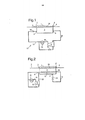
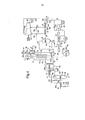
[0015] A presente invenção será agora ilustrada por meio de exemplo apenas, e com referência às formas de realização e aos desenhos esquemáticos não limitativos acompanhantes em que: a Fig. 1 mostra esquematicamente uma disposição de trocador de calor criogênico de acordo com uma forma de realização; a Fig. 2 mostra esquematicamente uma disposição de trocador de calor criogênico de acordo com outra forma de realização; a Fig- 3 mostra esquematicamente um diagrama de blocos de módulos para o resfriamento automático do trocador de calor criogênico da Fig. 1 ou Fig. 2; a Fig- 4 mostra esquematicamente uma disposição de trocador de calor criogênico principal de acordo com outra forma de realização da invenção como usada em um teste, a Fig- 5 mostra esquematicamente o alinhamento da Fig. 4 que ilustra as temperaturas e pressões monitoradas; a Fig. 6 mostra um diagrama de blocos dos módulos como usados no teste em conjunto com o alinhamento da Fig. 4; e, a Fig. 7 mostra esquematicamente uma estrutura alternativa de módulo que pode ser incorporada no diagrama de blocos da Fig. 6.[0015] The present invention will now be illustrated by way of example only, and with reference to the accompanying embodiments and non-limiting schematic drawings in which: Fig. 1 schematically shows a cryogenic heat exchanger arrangement according to a shape of achievement; Fig. 2 schematically shows a cryogenic heat exchanger arrangement according to another embodiment; Fig- 3 schematically shows a block diagram of modules for the automatic cooling of the cryogenic heat exchanger of Fig. 1 or Fig. 2; Fig- 4 schematically shows a main cryogenic heat exchanger arrangement according to another embodiment of the invention as used in a test, Fig-5 schematically shows the alignment of Fig. 4 which illustrates the monitored temperatures and pressures; Fig. 6 shows a block diagram of the modules as used in the test in conjunction with the alignment of Fig. 4; and, Fig. 7 schematically shows an alternative module structure that can be incorporated into the block diagram of Fig. 6.
[0016] Para o propósito desta descrição, um único número de referência será atribuído a uma linha (conduto), assim como uma corrente carregada nesta linha (conduto). Os mesmos números de referência se referem aos componentes, correntes ou linhas (condutos) similares.[0016] For the purpose of this description, a single reference number will be assigned to a line (conduit), as well as a current loaded on this line (conduit). The same reference numbers refer to similar components, chains or lines (conduits).
[0017] São descritos os métodos e aparelhos que empregam um controlador programável que recebe sinais de entrada que representam os sinais de sensor de uma ou mais variáveis controladas em um processo selecionado, e produz sinais de controle para controlar uma ou mais variáveis manipuladas no processo selecionado. O controlador programável pode executar um programa de computador que compreende uma rede de pelo menos três módulos.[0017] The methods and devices that employ a programmable controller that receives input signals that represent the sensor signals of one or more controlled variables in a selected process are described, and produces control signals to control one or more variables manipulated in the process selected. The programmable controller can run a computer program that comprises a network of at least three modules.
[0018] Uma tal divisão em módulos facilita ainda mais a flexibilidade e a facilidade de gerenciamento do processo de resfriamento, e a manutenção do controlador programável. Vários módulos podem manipular uma ou mais válvulas e possui pelo menos um alvo modular claramente definido. Os módulos podem operar de forma independente um do outro, mas pode haver variáveis comuns monitoradas por diversos módulos que podem ser afetados pela ação de mais do que um módulo. Este tipo de abordagem modular que emprega módulos independentemente executáveis, torna a invenção adequada para automatizar o resfriamento de qualquer tipo de trocador de calor, incluindo aqueles dos assim chamados tipo bobina enrolada e tipo placa de quilha.[0018] Such a division into modules further facilitates the flexibility and ease of management of the cooling process, and the maintenance of the programmable controller. Several modules can handle one or more valves and have at least one clearly defined modular target. The modules can operate independently of each other, but there may be common variables monitored by several modules that can be affected by the action of more than one module. This type of modular approach that employs independently executable modules, makes the invention suitable for automating the cooling of any type of heat exchanger, including those of the so-called coiled type and keel plate type.
[0019] Um ou mais dos pelo menos três módulos recebem uma representação de um ou mais dos sinais de entrada e produzem representações de um ou mais dos sinais de controle. Os pelo menos três módulos são cada um disposto para: (a) esperar até que um sinal de ativação seja recebido; e, (b) iniciar a execução de uma sequência predeterminada de uma ou mais instruções legíveis de computador após a recepção do sinal de ativação pelo menos até um alvo predeterminado do módulo para que o módulo seja alcançado.[0019] One or more of the at least three modules receive a representation of one or more of the input signals and produce representations of one or more of the control signals. The at least three modules are each arranged to: (a) wait until an activation signal is received; and, (b) initiate the execution of a predetermined sequence of one or more computer-readable instructions after receiving the activation signal at least to a predetermined target of the module for the module to be reached.
[0020] Um sinal de comunicação é gerado o qual marca se o módulo atingiu ou alcançou o alvo modular predeterminado. O sinal de comunicação pode ser gerado pelo próprio módulo, em outras partes do controlador programável, ou pode compreender, por exemplo, um sinal de sensor que indica que uma condição predeterminada ou em torno do trocador de calor criogênico foi atingida. O alvo modular predeterminado pode ser um resultado intermediário para o módulo, caso em que o módulo pode continuar a executar mais instruções legíveis por computador, por exemplo, para atingir um alvo modular adicional. Alternativamente, o sinal de comunicação pode ser a marcação da conclusão da execução do módulo.[0020] A communication signal is generated which marks whether the module has reached or reached the predetermined modular target. The communication signal can be generated by the module itself, in other parts of the programmable controller, or it can comprise, for example, a sensor signal that indicates that a predetermined condition in or around the cryogenic heat exchanger has been reached. The predetermined modular target can be an intermediate result for the module, in which case the module can continue to execute more computer-readable instructions, for example, to reach an additional modular target. Alternatively, the communication signal can be the marking of the completion of the module's execution.
[0021] Os módulos na rede estão interligados de tal maneira que o sinal de ativação recebido por um segundo e um terceiro módulo dos pelo menos três módulos corresponde a um sinal de comunicação que é gerado quando o primeiro módulo dos pelo menos três módulos atingiu o alvo predeterminado para este módulo.[0021] The modules in the network are interconnected in such a way that the activation signal received by a second and a third module from at least three modules corresponds to a communication signal that is generated when the first module of at least three modules has reached the predetermined target for this module.
[0022] Esta forma de interligação dos módulos leva em conta o controle de um processo sequencial em que pelo menos uma determinada tarefa necessita ser concluída antes de iniciar uma ou mais de outras tarefas, e em que as pelo menos duas tarefas necessitam ser realizadas uma após a outra, enquanto outras tarefas necessitam ser realizadas simultaneamente.[0022] This form of interconnection of the modules takes into account the control of a sequential process in which at least one particular task needs to be completed before starting one or more other tasks, and in which at least two tasks need to be performed one after another, while other tasks need to be performed simultaneously.
[0023] Não há nenhuma necessidade de prioridade de manejo das várias tarefas, pois cada módulo espera até que receba um sinal de ativação antes de poder começar a cumprir a sua tarefa, e isso gera um sinal de comunicação após a conclusão de sua tarefa. A conclusão da tarefa pode ser representada pelo sinal de comunicação que marca a realização de um alvo predeterminado associado com a tarefa para este módulo.[0023] There is no need for priority handling of the various tasks, as each module waits until it receives an activation signal before it can begin to perform its task, and this generates a communication signal after the completion of its task. The completion of the task can be represented by the communication signal that marks the achievement of a predetermined target associated with the task for this module.
[0024] Qualquer sinal que marca a conclusão do alvo modular predeterminado pode ser transmitido e/ou ser recebido por um ou mais dos próximos módulos que podem depois trabalhar em uma ou mais das próximas tarefas do processo sequencial. Quando o sinal de comunicação for recebido por dois ou mais dos próximos módulos, os dois ou mais dos próximos módulos estão prontos para iniciar a execução de suas instruções legíveis de computador em paralelo um com o outro.[0024] Any signal that marks the completion of the predetermined modular target can be transmitted and / or be received by one or more of the next modules that can then work on one or more of the next tasks of the sequential process. When the communication signal is received by two or more of the next modules, the two or more of the next modules are ready to start executing their computer-readable instructions in parallel with each other.
[0025] Para os propósitos de interpretação das presentes reivindicações e relatório descritivo, o sinal de comunicação pode ser gerado após atingir o alvo ou pode ser qualquer sinal que possa ser inferido em que o módulo atingiu o alvo predeterminado.[0025] For the purposes of interpreting the present claims and specification, the communication signal can be generated after reaching the target or it can be any signal that can be inferred that the module has reached the predetermined target.
[0026] Ficará entendido que o segundo e/ou o terceiro sinais de comunicação podem ser gerados quando o segundo e/ou o terceiro módulos tiverem alcançado os seus respectivos alvos modulares, em que o segundo e o terceiro sinais de comunicação podem atuar como sinal(s) de ativação para um ou mais módulos subsequentes ou ser utilizados de outra forma no procedimento.[0026] It will be understood that the second and / or third communication signals can be generated when the second and / or third modules have reached their respective modular targets, in which the second and third communication signals can act as a signal (s) of activation for one or more subsequent modules or to be used in another way in the procedure.
[0027] A tarefa em um módulo selecionado pode ter que ser realizada enquanto é ligada por alguma restrição em uma ou mais das variáveis controladas enquanto estas uma ou mais variáveis controladas não são controladas pelo módulo selecionado em questão, mas, por exemplo, por um outro módulo simultaneamente ativo. Em um tal caso, a execução da tarefa do módulo selecionado automaticamente experimentará um atraso se mais adiante a execução de sua tarefa levar a uma violação da referida restrição. Este atraso pode terminar quando o outro módulo, que influencia a variável controlada, avança na execução de sua tarefa de tal forma que a restrição é retirada ou deslocada dando espaço para o módulo selecionado em questão avançar ainda mais na execução de sua tarefa.[0027] The task in a selected module may have to be performed while it is linked by some restriction on one or more of the controlled variables while these one or more controlled variables are not controlled by the selected module in question, but, for example, by a another module simultaneously active. In such a case, the task execution of the selected module will automatically experience a delay if further execution of its task leads to a violation of that restriction. This delay can end when the other module, which influences the controlled variable, advances in the execution of its task in such a way that the constraint is removed or moved, giving space for the selected module in question to advance further in the execution of its task.
[0028] Assim, um efeito da estrutura da rede proposta dos módulos que envolvem módulos independentes que operam em paralelo uns com os outros por meio do quais uma ação de controle de um dos módulos é restrita por uma variável que é influenciada pela manipulação de uma ou mais variáveis manipulada por outro módulo, é que as tarefas do módulo são quase sequencialmente executadas quando necessário e se possível simultaneamente. Isto torna este tipo de rede de módulo excelentemente adequado para uma operação tal como o resfriamento de um trocador de calor criogênico dentro de certas restrições.[0028] Thus, an effect of the proposed network structure of the modules that involve independent modules that operate in parallel with each other through which a control action of one of the modules is restricted by a variable that is influenced by the manipulation of a or more variables handled by another module, is that the module's tasks are almost sequentially executed when necessary and if possible simultaneously. This makes this type of module network excellently suited for an operation such as cooling a cryogenic heat exchanger within certain restrictions.
[0029] Uma opção adicional para a interligação de pelo menos dois dos módulos é que um sinal de conteúdo é gerado em um módulo que é recebido por um outro módulo e provoca uma mudança na operação do módulo diferente da partida deste módulo. Por exemplo, o sinal de conteúdo pode ativar uma mudança de parâmetro no outro módulo quando uma determinada condição for alcançada no primeiro módulo que faz com que o sinal de conteúdo seja gerado.[0029] An additional option for the interconnection of at least two of the modules is that a content signal is generated in a module that is received by another module and causes a change in the operation of the module other than the start of this module. For example, the content signal can activate a parameter change in the other module when a certain condition is reached in the first module that causes the content signal to be generated.
[0030] A rede de módulos pode ser de tal forma que o sinal de ativação que marca o início da execução das instruções predeterminadas para um módulo particular, pode ser o sinal de ativação recebido por este módulo, por meio do qual pode ser qualquer número natural. Por exemplo, um módulo selecionado pode necessitar esperar para, por exemplo, três outros módulos atingir os seus alvos após o que o sinal de comunicação é gerado, antes que ele possa começar a executar sua sequência de instruções legíveis por computador. Em um tal caso, pode ter que esperar até que tenha recebido três sinais de comunicação atuando como sinais de ativação, e assim o sinal de ativação relevante, que marca o início da execução da sequência predeterminada de instruções para um módulo particular, é neste exemplo precedido por dois sinais de ativação mais no princípio.[0030] The network of modules can be such that the activation signal that marks the beginning of the execution of the predetermined instructions for a particular module, can be the activation signal received by this module, through which it can be any number Natural. For example, a selected module may need to wait for, for example, three other modules to reach their targets after which the communication signal is generated, before it can start executing its sequence of computer-readable instructions. In such a case, you may have to wait until you have received three communication signals acting as activation signals, and so the relevant activation signal, which marks the beginning of the execution of the predetermined sequence of instructions for a particular module, is in this example preceded by two activation signals more at the beginning.
[0031] O controlador programável pode estar incorporado em um sistema de controle distribuído (DCS), em que, por exemplo, os módulos fornecem uma saída através de um servidor de interface, tal como um OLE (ligação e incorporação de objetos), para o controle de processo (OPC) que pode se comunicar entre o programa de computador e vários blocos de interface que podem estar presentes no DCS. Em uma tal disposição, o DCS pode retomar o controle das variáveis manipuladas (tais como as válvulas selecionadas) sem esperar pelo controlador programável para transferir o controle como pode ser desejado durante as situações de emergência ou coisa parecida.[0031] The programmable controller can be incorporated in a distributed control system (DCS), in which, for example, the modules provide an output through an interface server, such as an OLE (connection and incorporation of objects), for the process control (OPC) that can communicate between the computer program and various interface blocks that may be present in the DCS. In such an arrangement, the DCS can resume control of the manipulated variables (such as the selected valves) without waiting for the programmable controller to transfer control as may be desired during emergency situations or the like.
[0032] Os inventores associados com o presente pedido de patente têm contemplado que o tipo atualmente divulgado de controlador programável é de maneira ideal adequado para a automação do resfriamento de um trocador de calor criogênico adaptado para liquefazer uma corrente de hidrocarboneto, tal como uma corrente de gás natural.[0032] The inventors associated with the present patent application have contemplated that the currently disclosed type of programmable controller is ideally suited for automating the cooling of a cryogenic heat exchanger adapted to liquefy a hydrocarbon stream, such as a stream of natural gas.
[0033] O resfriamento automatizado de um trocador de calor criogênico vantajosamente facilita o resfriamento do trocador de calor criogênico na taxa mais alta possível, sem exceder a taxa máxima especificada de mudança de temperatura. Quando se resfria o trocador de calor criogênico sob controle manual, um operador tipicamente tem de manter uma margem mais ampla entre a taxa de mudança de temperatura e a máxima especificada.[0033] The automated cooling of a cryogenic heat exchanger advantageously facilitates the cooling of the cryogenic heat exchanger at the highest possible rate, without exceeding the specified maximum rate of temperature change. When the cryogenic heat exchanger is cooled under manual control, an operator typically has to maintain a wider margin between the rate of temperature change and the specified maximum.
[0034] Além disso, a experiência revelou que em cerca de 30 % do tempo, a taxa máxima especificada de mudança de temperatura é ultrapassada inadvertidamente, devido à complexidade da operação. Graças à automação como aqui descrita, se espera que este percentual seja reduzido significativamente. Os inventores estimam que a ultrapassagem da taxa máxima de mudança de temperatura pode ser reduzida em cerca de 12 % do tempo, ou pelo menos do que 15 % do tempo.[0034] In addition, experience has shown that in about 30% of the time, the specified maximum rate of temperature change is inadvertently exceeded due to the complexity of the operation. Thanks to automation as described here, this percentage is expected to be significantly reduced. The inventors estimate that exceeding the maximum rate of temperature change can be reduced by about 12% of the time, or at least 15% of the time.
[0035] Além do mais, os métodos e aparelhos aqui divulgados também podem ser usados para evitar um ou mais gradientes de temperatura espacial no ou em torno do trocador de calor criogênico de exceder um valor máximo recomendado.[0035] Furthermore, the methods and apparatus disclosed herein can also be used to prevent one or more spatial temperature gradients in or around the cryogenic heat exchanger from exceeding a recommended maximum value.
[0036] As vantagens dos métodos e aparelhos aqui descritos são mais acentuadas para o resfriamento nos trocadores térmicos criogênicos contra- correntes, de preferência usando um refrigerante externo, em que a evaporação dos fluxos refrigerantes contra-correntemente em relação à corrente ou correntes que devem ser esfriadas no trocador de calor criogênico em contato com o refrigerante de evaporação, do que para o resfriamento dos trocadores térmicos criogênicos co-correntes.[0036] The advantages of the methods and devices described here are more accentuated for cooling in counter-current cryogenic heat exchangers, preferably using an external refrigerant, in which the evaporation of refrigerant flows counter-current in relation to the current or currents that must be cooled in the cryogenic heat exchanger in contact with the evaporating refrigerant, than for cooling co-current cryogenic heat exchangers.
[0037] Os métodos e aparelhos aqui divulgados fazem uso das chamadas variáveis manipuladas e variáveis controladas. Além disso, há também, opcionalmente, uma ou mais variáveis monitoradas.[0037] The methods and devices disclosed here make use of the so-called manipulated variables and controlled variables. In addition, there are also, optionally, one or more monitored variables.
[0038] No relatório descritivo e nas reivindicações o termo ‘Variável manipulada’ é usado para se referir às variáveis que estão sujeitas às ações de controlo pelo controlador programável, e o termo ‘variáveis controladas’ é usado para se referir às variáveis que devem ser mantidas pelo controlador programável em um valor predeterminado (mais adiante referido como “ponto de fixação”) ou dentro de uma faixa predeterminada (“faixa de fixação”). O ponto de fixação ou faixa de fixação não deve ser uma entidade fixa. De fato, muitas vezes estará sujeito a alterações (calculado durante o resfriamento, ou como uma sequência predeterminada ao longo do tempo). Como uma variável controlada, uma ‘variável monitorada’ é medida e opcionalmente registrada, mas em contraste com uma variável controlada, não deve ser mantida pelo controlador programável em um ponto de fixação ou dentro de uma faixa de fixação. No entanto, as variáveis monitoradas podem servir como entrada para o controlador programável para que possa tomar decisões com base nestas variáveis monitoradas, ou para gerar sinais de comunicação, ou, por exemplo, dar origem ao controlador programável para emitir um sinal de alerta ou para fazer uma pausa e/ou abortar o procedimento automático.[0038] In the specification and in the claims the term 'Variable manipulated' is used to refer to variables that are subject to control actions by the programmable controller, and the term 'controlled variables' is used to refer to variables that must be maintained by the programmable controller at a predetermined value (hereinafter referred to as “fixation point”) or within a predetermined range (“fixation range”). The attachment point or attachment band must not be a fixed entity. In fact, it will often be subject to change (calculated during cooling, or as a predetermined sequence over time). As a controlled variable, a 'monitored variable' is measured and optionally recorded, but in contrast to a controlled variable, it must not be maintained by the programmable controller at a fixation point or within a fixation range. However, the monitored variables can serve as input to the programmable controller so that it can make decisions based on these monitored variables, or to generate communication signals, or, for example, give rise to the programmable controller to emit an alert signal or to pause and / or abort the automatic procedure.
[0039] Preferivelmente, a uma ou mais variáveis controladas compreendem uma taxa de alteração na temperatura ao longo do tempo de um ou mais de: temperatura do refrigerante do lado de sucção da primeira válvula JT; temperatura do refrigerante no lado de descarga da primeira válvula JT; temperatura da corrente de hidrocarboneto em um ponto dentro do trocador de calor criogênico; e, temperatura da corrente de hidrocarboneto a jusante do trocador de calor criogênico. Isto fornece uma indicação direta que facilita ainda mais o resfriamento do trocador de calor criogênico sem exceder a taxa máxima especificada de mudança de temperatura.[0039] Preferably, the one or more controlled variables comprise a rate of change in temperature over time of one or more of: refrigerant temperature on the suction side of the first JT valve; refrigerant temperature on the discharge side of the first JT valve; temperature of the hydrocarbon stream at a point within the cryogenic heat exchanger; and, temperature of the hydrocarbon stream downstream of the cryogenic heat exchanger. This provides a direct indication that further facilitates the cooling of the cryogenic heat exchanger without exceeding the specified maximum rate of temperature change.
[0040] Em lugar de, ou em combinação com a taxa de mudança na temperatura, a uma ou mais variáveis controladas podem compreender um gradiente de temperatura selecionado em ou ao redor do trocador de calor criogênico. Isso facilita o resfriamento do trocador de calor criogênico sem ultrapassar um gradiente de temperatura espacial máximo especificado. Um gradiente de temperatura espacial adequado para manter dentro de um máximo predeterminado é o gradiente de temperatura entre um tubo refrigerante e a parede da estrutura.[0040] In place of, or in combination with, the rate of change in temperature, one or more controlled variables may comprise a temperature gradient selected in or around the cryogenic heat exchanger. This facilitates the cooling of the cryogenic heat exchanger without exceeding a specified maximum spatial temperature gradient. A suitable spatial temperature gradient to keep within a predetermined maximum is the temperature gradient between a refrigerant pipe and the structure wall.
[0041] Como será observado pela pessoa versada na técnica, a taxa de mudança de temperatura máxima e/ou o gradiente de temperatura espacial máximo é geralmente dependente do tipo e/ou projeto específico do trocador de calor que está sujeita ao processo de resfriamento. As recomendações específicas sobre tais valores podem ser fornecidas pelo fabricante.[0041] As will be noted by the person skilled in the art, the rate of maximum temperature change and / or the maximum spatial temperature gradient is generally dependent on the specific type and / or design of the heat exchanger that is subject to the cooling process. Specific recommendations on such values can be provided by the manufacturer.
[0042] Quando o trocador de calor criogênico compreende um lado da estrutura para a evaporação do refrigerante e um lado do tubo para o auto- resfriamento do refrigerante, o gradiente de temperatura espacial selecionado pode refletir o diferencial de temperatura entre um lado da estrutura do trocador de calor criogênico e um lado do tubo contendo refrigerante.[0042] When the cryogenic heat exchanger comprises one side of the structure for the evaporation of the refrigerant and one side of the tube for the self-cooling of the refrigerant, the selected spatial temperature gradient may reflect the temperature differential between one side of the structure of the refrigerant cryogenic heat exchanger and one side of the tube containing refrigerant.
[0043] Existem outros gradientes de temperatura preferidos a serem usados, por exemplo, em alinhamentos em que a jusante do refrigerante e a montante da primeira válvula JT um separador de líquido/vapor é fornecido no circuito de recirculação do refrigerante, para receber um refrigerante parcialmente condensado e separar a corrente de refrigerante parcialmente condensado em uma fração pesada de refrigerante líquido e uma fração leve de refrigerante gasoso e para descarregar a fração pesada de refrigerante líquido através de uma saída de líquido e a fração leve de refrigerante gasoso através de uma saída de gás, em que as frações são passadas pelo trocador de calor criogênico em que a primeira válvula JT é disposta para controlar a passagem de uma destas frações, preferivelmente a fração leve de refrigerante.[0043] There are other preferred temperature gradients to be used, for example, in alignments where downstream of the refrigerant and upstream of the first JT valve a liquid / vapor separator is provided in the refrigerant recirculation circuit, to receive a refrigerant partially condensed and separate the partially condensed refrigerant stream into a heavy fraction of liquid refrigerant and a light fraction of carbonated refrigerant and to discharge the heavy fraction of liquid refrigerant through a liquid outlet and the light fraction of carbonated refrigerant through an outlet gas, in which the fractions are passed through the cryogenic heat exchanger in which the first JT valve is arranged to control the passage of one of these fractions, preferably the light refrigerant fraction.
[0044] O gradiente de temperatura espacial selecionado pode em um tal alinhamento refletir um ou mais do: diferencial de temperatura entre o refrigerante gasto e o refrigerante entre a saída de gás e a entrada do refrigerante gasoso do trocador de calor criogênico; e, diferencial de temperatura entre o refrigerante gasto e o refrigerante entre a saída de líquido e a entrada do refrigerante líquido do trocador de calor criogênico.[0044] The selected spatial temperature gradient may in such an alignment reflect one or more of the: temperature differential between the spent refrigerant and the refrigerant between the gas outlet and the gas refrigerant inlet of the cryogenic heat exchanger; and, temperature differential between the spent refrigerant and the refrigerant between the liquid outlet and the liquid refrigerant inlet of the cryogenic heat exchanger.
[0045] Outras possíveis variáveis controladas incluem as variáveis indicativas das condições de operação de um ou mais compressores, tais como as condições de onda. Um assim chamado parâmetro de desvio de onda pode ser determinado com base nos dados do sensor para quantificar o desvio entre a onda e as condições reais de operação do compressor. Os dados de sensor típicos que são levados em conta para a determinação do parâmetro de desvio de onda incluem o fluxo através do estágio de compressor relevante e a pressão de admissão e descarga do estágio relevante.[0045] Other possible controlled variables include variables indicative of the operating conditions of one or more compressors, such as wave conditions. A so-called wave deviation parameter can be determined based on the sensor data to quantify the deviation between the wave and the actual operating conditions of the compressor. Typical sensor data that is taken into account for determining the wave deviation parameter includes the flow through the relevant compressor stage and the inlet and discharge pressure of the relevant stage.
[0046] Para automaticamente esfriar um trocador de calor criogênico, a um ou mais variáveis manipuladas podem compreender um ou ambos de: uma primeira regulagem de válvula JT que representa uma medida da quantidade de abertura da primeira válvula JT; e, uma regulagem da válvula de reciclo do compressor que representa uma medida da quantidade de abertura da válvula de reciclo do compressor. A quantidade de abertura da primeira válvula JT afeta muito diretamente a taxa de esfriamento do trocador de calor criogênico, porque é um dos fatores que determinam o efeito Joule- Thomson que a válvula JT possui sobre a corrente de refrigerante quando ele passa através da válvula JT, que determina o poder de esfriamento do refrigerante. A quantidade de abertura da válvula de reciclo do compressor também afeta a taxa de esfriamento do trocador de calor criogênico porque também influencia o efeito JT na primeira válvula JT porque é uma forma de controlar a pressão e a taxa de fluxo do refrigerante.[0046] To automatically cool a cryogenic heat exchanger, one or more manipulated variables can comprise one or both of: a first JT valve regulation that represents a measure of the opening quantity of the first JT valve; and, a regulation of the compressor recycling valve that represents a measure of the amount of opening of the compressor recycling valve. The amount of opening of the first JT valve directly affects the cooling rate of the cryogenic heat exchanger, because it is one of the factors that determine the Joule-Thomson effect that the JT valve has on the refrigerant current when it passes through the JT valve , which determines the cooling power of the refrigerant. The amount of opening of the compressor recycle valve also affects the cooling rate of the cryogenic heat exchanger because it also influences the JT effect on the first JT valve because it is a way of controlling the refrigerant pressure and flow rate.
[0047] Naturalmente, existem outras variáveis manipuladas que podem controlar a pressão e/ou a taxa de fluxo do refrigerante, tais como a velocidade do compressor. Assim, a velocidade do compressor também pode ser usada como uma das variáveis manipuladas. No entanto, em contraste com a velocidade, uma válvula é um item muito adequado para manipular em uma sequência de controle que tem um efeito relativamente imediato sobre a pressão.[0047] Of course, there are other manipulated variables that can control the pressure and / or flow rate of the refrigerant, such as the speed of the compressor. Thus, the compressor speed can also be used as one of the manipulated variables. However, in contrast to speed, a valve is a very suitable item to handle in a control sequence that has a relatively immediate effect on pressure.
[0048] Os métodos e aparelhos aqui divulgados podem ser utilizados em um método de liquefação de uma corrente de hidrocarboneto tal como uma corrente de gás natural. Em um tal caso, o resfriamento do trocador de calor criogênico é seguido pela operação normal em que a corrente de hidrocarboneto é esfriada no trocador de calor criogênico até que ele seja liquefeito, preferivelmente, seguido pelo sub-esfriamento no trocador de calor criogênico ou em um subsequente trocador de calor.[0048] The methods and apparatus disclosed herein can be used in a method of liquefying a hydrocarbon stream such as a stream of natural gas. In such a case, cooling of the cryogenic heat exchanger is followed by normal operation in which the hydrocarbon stream is cooled in the cryogenic heat exchanger until it is liquefied, preferably followed by subcooling in the cryogenic heat exchanger or in a subsequent heat exchanger.
[0049] É desejável liquefazer uma corrente de gás natural por várias razões. Como um exemplo, o gás natural pode ser armazenado e transportado por longas distâncias mais rapidamente como um líquido do que na forma gasosa, porque ele ocupa um volume menor e não precisa ser armazenado em uma pressão elevada.[0049] It is desirable to liquefy a stream of natural gas for several reasons. As an example, natural gas can be stored and transported over long distances more quickly as a liquid than in gaseous form, because it occupies a smaller volume and does not need to be stored at high pressure.
[0050] Geralmente, o gás natural compreendendo predominantemente metano, entra em uma usina de LNG em pressões elevadas e é pré-tratado para produzir uma carga de alimentação purificada adequado para a liquefação em temperaturas criogênicas. O gás purificado é processado através de uma pluralidade de estágios de esfriamento usando trocadores térmicos para progressivamente reduzir a sua temperatura até que a liquefação seja alcançada. O gás natural líquido é depois ainda opcionalmente esfriado, e expandido através de um ou mais estágios de expansão na pressão atmosférica final adequada para o armazenamento e transporte. O vapor ocorrido subitamente de cada estágio de expansão pode ser usado como uma fonte de gás combustível da usina.[0050] Generally, natural gas, predominantly methane, enters an LNG plant at high pressures and is pre-treated to produce a purified feed charge suitable for liquefaction at cryogenic temperatures. The purified gas is processed through a plurality of cooling stages using heat exchangers to progressively reduce its temperature until liquefaction is achieved. The liquid natural gas is then further optionally cooled, and expanded through one or more expansion stages at the final atmospheric pressure suitable for storage and transportation. The steam that suddenly occurs from each expansion stage can be used as a source of fuel gas for the plant.
[0051] É observado que a US 2006/0213223 Al divulga uma usina de liquefação e método para a produção de gás natural liquefeito. O controle da usina pode ser total ou parcialmente automatizado, tal como mediante o uso de um computador apropriado, um circuito lógico programável (PLC), usando esquema de circuito fechado e circuito aberto, utilizando o controle proporcional, integral, derivado (PID). No entanto, a US 2006/0213223 não ensina um programa de computador ou um algoritmo como descrito no presente pedido.[0051] It is observed that US 2006/0213223 Al discloses a liquefaction plant and method for the production of liquefied natural gas. The control of the plant can be totally or partially automated, such as by using an appropriate computer, a programmable logic circuit (PLC), using a closed circuit and open circuit scheme, using proportional, integral, derivative control (PID). However, US 2006/0213223 does not teach a computer program or algorithm as described in the present application.
[0052] Como esquematicamente mostrado na Fig. 1, é fornecido um trocador de calor criogênico 1 disposto para receber, através do conduto 2 e da entrada da corrente de hidrocarboneto 7, a corrente de hidrocarboneto que deve ser liquefeita, de modo a trocar o calor entre a corrente de hidrocarboneto e pelo menos um refrigerante de evaporação parcial 3. Como resultado da troca de calor, a corrente de hidrocarboneto pode ser pelo menos parcialmente liquefeita. A corrente de hidrocarboneto preferivelmente pelo menos parcialmente liquefeita é descarregada através da saída da corrente de hidrocarboneto 8 no conduto 4. Na forma de realização como estabelecida, o conduto 2 e o conduto 4 se conecta através de um lado do tubo 29. No entanto, outros tipos de trocadores térmicos são possíveis.[0052] As schematically shown in Fig. 1, a
[0053] O trocador de calor criogênico 1 compreende uma entrada de refrigerante 5 para um refrigerante externo e uma saída de refrigerante 6 para o refrigerante gasto que passou através do trocador de calor criogênico. Um circuito de recirculação do refrigerante 10 é fornecido para recircular o refrigerante gasto de volta para a entrada 5. O circuito de recirculação do refrigerante 10 compreende, pelo menos, um compressor 11, uma válvula de reciclo do compressor 12, um refrigerador 13, e uma primeira válvula Joule- Thompson (primeira JT) 14.[0053] The
[0054] Nas formas de realização práticas da invenção, uma válvula JT pode ser usada em combinação com um expansor. No entanto, em particular durante o resfriamento do trocador de calor, a válvula JT é preferivelmente usada para controlar o esfriamento.[0054] In the practical embodiments of the invention, a JT valve can be used in combination with an expander. However, in particular when cooling the heat exchanger, the JT valve is preferably used to control cooling.
[0055] Nas formas de realização práticas da invenção, o compressor pode consistir de uma pluralidade de estágios de compressão, por exemplo, 15 estágios de compressão ou mais. Um número destes estágios, por exemplo, 15 destes estágios, pode ser fornecido na forma de um compressor axial ou compressor de centrífuga em um invólucro. Cada estágio pode compreender uma válvula de reciclo aplicada, e/ou uma válvula de reciclo única pode ser compartilhada por qualquer número de estágios subsequentes. Vários compressores ou invólucros de compressor podem ser dispostos em série um após o outro para formar uma fileira de compressores. Cada invólucro (ou estágio de compressor) pode ser seguido por qualquer número de refrigeradores opcionais (ou interrefrigeradores), e tambores de tombo para remover qualquer líquido do vapor comprimido antes de passar o vapor comprimido no próximo estágio de compressão. Após o último estágio de compressão, a corrente de refrigerante comprimida pode ser esfriada.[0055] In the practical embodiments of the invention, the compressor may consist of a plurality of compression stages, for example, 15 compression stages or more. A number of these stages, for example, 15 of these stages, can be provided in the form of an axial compressor or a centrifugal compressor in an enclosure. Each stage can comprise an applied recycle valve, and / or a single recycle valve can be shared by any number of subsequent stages. Several compressors or compressor housings can be arranged in series one after another to form a row of compressors. Each enclosure (or compressor stage) can be followed by any number of optional coolers (or intercoolers), and tumble drums to remove any liquid from the compressed vapor before passing the compressed vapor to the next compression stage. After the last stage of compression, the compressed refrigerant stream can be cooled.
[0056] No entanto, para o propósito de ilustrar a presente invenção, um compressor esquematicamente simplificado colocado em alinhamento é mostrado nas Figs. 1 e 2, com apenas um compressor desenhado em uma válvula de reciclo.[0056] However, for the purpose of illustrating the present invention, a schematically simplified compressor placed in alignment is shown in Figs. 1 and 2, with only one compressor designed on a recycle valve.
[0057] Em operação, o refrigerante gasto (pelo menos parcialmente evaporado) é retirado do trocador de calor 1 através de uma saída 6, e pelo menos uma parte é passada para uma entrada de sucção do compressor 11 através do conduto 25.[0057] In operation, the spent refrigerant (at least partially evaporated) is removed from the
[0058] A parte gasosa da corrente de refrigerante gasto no conduto 25 é comprimida para produzir um corrente de refrigerante comprimida 16 que é subsequentemente esfriada em um ou mais refrigeradores, aqui representado como refrigerador 13, desse modo pelo menos parcialmente condensando a corrente de refrigerante comprimida 16 para formar pelo menos uma corrente de refrigerante parcialmente condensada 17. A pelo menos uma corrente de refrigerante parcialmente condensada 17 é ampliada sobre a primeira válvula JT 14 e subsequentemente levado para o trocador de calor 1 através de uma entrada 5.[0058] The gaseous portion of the refrigerant stream spent in the
[0059] Como mostrado na Fig. 1, a corrente de refrigerante flui co- correntemente com a corrente de hidrocarboneto (da esquerda para a direita) através de um trocador de calor 1. No entanto, o fluxo pode ser disposto contra-correntemente ao invés disso, tal como é o caso, por exemplo, na Fig. 2.[0059] As shown in Fig. 1, the refrigerant current flows co-current with the hydrocarbon current (from left to right) through a
[0060] Na figura. 2, uma disposição alternativa de trocador de calor criogênico é apresentada que compreende os mesmos elementos como a forma de realização da Fig. 1, e, além disso, inclui um lado do tubo refrigerante 15 para o auto-resfriamento do refrigerante. Tanto a corrente de hidrocarboneto 2 quanto o refrigerante são submetidos a troca térmica em contato com a evaporação do refrigerante no trocador de calor 1. A corrente de refrigerante comprimido 16 é subsequentemente esfriada em um ou mais refrigeradores, aqui representados como refrigerador 13, seguido pelo esfriamento no trocador de calor 1, através do lado do tubo 15, pelo menos assim parcialmente condensando a corrente de refrigerante comprimida 16 para formar pelo menos a corrente de refrigerante parcialmente condensada 17. Pelo menos a corrente de refrigerante parcialmente condensada auto- esfriada 17, é removida do trocador de calor na saída 18 e levada através da primeira válvula JT 14 antes que ela seja passada através da entrada 5, no trocador de calor 1, onde é deixada para pelo menos parcialmente evaporar.[0060] In the figure. 2, an alternative cryogenic heat exchanger arrangement is presented which comprises the same elements as the embodiment of Fig. 1, and furthermore includes a side of the
[0061] Opcionalmente, um sistema de preparação de refrigerante pode ser fornecido que é capaz de mudar o inventário do refrigerante, em particular no caso de um refrigerante misturado.[0061] Optionally, a refrigerant preparation system can be provided that is capable of changing the refrigerant inventory, particularly in the case of a mixed refrigerant.
[0062] Os inventores verificaram que a sequência de etapas e tarefas pelas quais um trocador de calor criogênico é melhor resfriado, pode de forma ideal ser automatizada usando um controlador programável como aqui descrito, em que uma ou mais de: - uma taxa de alteração na temperatura do refrigerante no lado de sucção da primeira válvula JT; - uma taxa de alteração na temperatura do refrigerante no lado de descarga da primeira válvula JT; - uma taxa de alteração na temperatura da corrente de hidrocarboneto em um ponto dentro do trocador de calor criogênico; - uma taxa de alteração na temperatura da corrente de hidrocarboneto a jusante do trocador de calor criogênico; - um primeiro diferencial de temperatura na corrente de refrigerante através da primeira válvula JT (diferença na temperatura do refrigerante no lado de sucção da primeira válvula JT e do refrigerante no lado de descarga da primeira válvula JT); - um gradiente de temperatura que reflete o diferencial de temperatura entre o refrigerante gasto (na ou próximo da saída 6 ou conduto 25) e o refrigerante na entrada 5 do trocador de calor criogênico 1; - um gradiente de temperatura que reflete o diferencial de temperatura entre um lado da estrutura do trocador de calor criogênico 3 e um lado do tubo de contendo refrigerante (tal como o lado do tubo 15); - uma pressão de sucção na corrente de refrigerante em um lado de sucção do compressor; são utilizados como variáveis controladas, enquanto: - a regulagem da primeira válvula JT, por exemplo, que representa uma medida da quantidade de abertura da primeira válvula JT (Xu) ou do fluxo através da primeira válvula JT; e,/ou - uma regulagem da válvula de reciclo do compressor, por exemplo, que representa uma medida da quantidade de abertura da válvula de reciclo do compressor (X12) ou do fluxo através da válvula de reciclo; são utilizadas como variáveis manipuladas. Quando um sistema de preparação for fornecido, as válvulas de preparação dos componentes de refrigerante também podem ser utilizadas como variáveis manipuladas.[0062] The inventors have found that the sequence of steps and tasks by which a cryogenic heat exchanger is best cooled, can ideally be automated using a programmable controller as described here, where one or more of: - a rate of change the temperature of the refrigerant on the suction side of the first JT valve; - a rate of change in the refrigerant temperature on the discharge side of the first JT valve; - a rate of change in the temperature of the hydrocarbon stream at a point within the cryogenic heat exchanger; - a rate of change in the temperature of the hydrocarbon stream downstream of the cryogenic heat exchanger; - a first temperature differential in the refrigerant stream through the first JT valve (difference in the temperature of the refrigerant on the suction side of the first JT valve and of the refrigerant on the discharge side of the first JT valve); - a temperature gradient that reflects the temperature differential between the spent refrigerant (at or near outlet 6 or conduit 25) and the refrigerant at entry 5 of the cryogenic heat exchanger 1; - a temperature gradient that reflects the temperature differential between one side of the cryogenic heat exchanger structure 3 and one side of the refrigerant-containing tube (such as the side of the tube 15); - a suction pressure in the refrigerant stream on one side of the compressor; they are used as controlled variables, while: - the regulation of the first JT valve, for example, which represents a measure of the opening quantity of the first JT valve (Xu) or the flow through the first JT valve; and / or - a regulation of the compressor recycling valve, for example, which represents a measure of the amount of opening of the compressor recycling valve (X12) or of the flow through the recycling valve; are used as manipulated variables. When a preparation system is provided, the refrigerant component preparation valves can also be used as manipulated variables.
[0063] Além disso, uma ou mais de: - uma ou mais temperaturas absolutas em um ou mais locais no ou em torno do trocador de calor criogênico; e, - pressão de descarga do compressor; podem ser usadas como variável controlada.[0063] In addition, one or more of: - one or more absolute temperatures at one or more locations in or around the cryogenic heat exchanger; and, - compressor discharge pressure; can be used as a controlled variable.
[0064] A Figura 3 mostra um diagrama de blocos esquemático contendo uma estrutura de módulo de exemplo do programa de computador no controlador programável para o método e aparelho de resfriamento automático. Um primeiro módulo 201 define as condições iniciais. O módulo 201 pode conter uma interface gráfica com um resumo dos avisos e modos de informação. Pode conter informação sobre as condições iniciais críticas e não críticas. Em caso de ocorrência de uma condição crítica, o módulo termina o programa de computador, desse modo interrompendo o procedimento. O procedimento pode ser retomado e/ou reiniciado após a condição crítica ter sido resolvida, manualmente por um operador ou pela execução de um procedimento de controle automatizado para restaurar a condição inicial. No caso de uma condição inicial não crítica, o módulo de 201 emite um aviso. Este módulo pode ainda iniciar o monitoramento das variáveis críticas. O alvo do módulo é atingido quando todas as variáveis críticas estão dentro das faixas predeterminadas. A ativação final pode então ser gerada.[0064] Figure 3 shows a schematic block diagram containing an example module structure of the computer program in the programmable controller for the method and automatic cooling device. A
[0065] Exemplos de condições iniciais críticas são: - a primeira válvula JV 14 não é suficientemente fechada (por exemplo, mais de 0,1 % aberta ou outro número adequado); - a pressão no circuito refrigerante é mais baixa do que a descarga do compressor 11; - o compressor 11 não está em linha e em execução, como pode ser determinado através da medição da velocidade do compressor (por exemplo, o compressor funcionando pelo menos a 3400 rpm ou outra velocidade adequada), e a verificação de que as válvulas de sucção e descarga nos compressores estão abertas; - a pressão do refrigerante é muito elevada (por exemplo, acima de 20 barg, por exemplo, ou outra estimativa adequada); - a palheta guia de entrada do compressor (IGV) é aberta.[0065] Examples of critical initial conditions are: - the
[0066] Exemplos de condições iniciais não críticas são: - várias temperaturas reais, por exemplo, temperatura do refrigerante diretamente a montante e diretamente a jusante da primeira válvula JV 14, e/ou diferenciais de temperatura; - as válvulas de reciclo do compressor não estão totalmente abertas (por exemplo, menos do que 99 % aberto ou qualquer outro valor adequado); e, - a pressão do refrigerante comprimido abaixo de um valor mínimo predeterminado (pois isso pode desnecessariamente atrasar os processos de resfriamento). Um valor mínimo tipicamente adequado é de 18 barg.[0066] Examples of non-critical initial conditions are: - various actual temperatures, for example, refrigerant temperature directly upstream and directly downstream of the
[0067] Claramente, o módulo 201 pode ser precedido por um ou mais outros módulos, por exemplo, módulos relacionados com o resfriamento para um nível de temperatura intermediário ou semelhante, e ele pode começar após a recepção de um ou mais sinais de ativação.[0067] Clearly,
[0068] Assim que o sinal de comunicação é gerado, pode ser emitido e recebido pelo módulo 202, que possui um primeiro alvo modular que se abre a partir da primeira válvula JT 14. Isto pode envolver um algoritmo que leva em conta qualquer comportamento não linear da válvula JT. Logo que uma tendência de esfriamento é detectada, a válvula será fechada parcialmente para evitar uma taxa de esfriamento muito elevada.[0068] As soon as the communication signal is generated, it can be emitted and received by
[0069] O sinal de comunicação do módulo 202 (ou um sinal correspondente) ativa o módulo 203, que depois começa por simplesmente esperar algum tempo. O propósito é esperar pelo aparelho estabilizar após a primeira ação crítica do módulo 202. O tempo de espera pode depender da condição final do módulo 202.[0069] The communication signal of module 202 (or a corresponding signal) activates
[0070] Um sinal correspondente ao sinal de comunicação do módulo 203 é recebido por dois módulos (204, 205), que são consequentemente ativados simultaneamente.[0070] A signal corresponding to the communication signal of
[0071] O módulo 204 ainda abre a primeira válvula JT 14. Em particular, na forma de realização da Fig. 2, o forte esfriamento pode causar a condensação do refrigerante. Pouco antes que a condensação ocorra, os movimentos da válvula são preferivelmente diminuídos, e o momento em que a condensação é detectada a válvula pode ser fechada parcialmente para evitar uma taxa de esfriamento muito elevada que de outra maneira seria motivada por um aumento repentino na taxa de fluxo devido à condensação (um aumento de 100 tpd em 10 se vê que não é comum). Depois que a condensação é detectada, a abertura da válvula pode ser normalizada e contínua até que o efeito JT da abertura da válvula seja diminuído. Este é o alvo do módulo.[0071]
[0072] O efeito JT pode ser monitorado durante a outra abertura da válvula JT, por exemplo, com base em uma diferença de temperatura entre a temperatura do refrigerante a montante da válvula JT e a temperatura do refrigerante a jusante da válvula JT. Uma hipótese pode ser feita de que o efeito JT está presente se a diferença de temperatura excede a 8°C.[0072] The JT effect can be monitored during the other opening of the JT valve, for example, based on a temperature difference between the refrigerant temperature upstream of the JT valve and the refrigerant temperature downstream of the JT valve. A hypothesis can be made that the JT effect is present if the temperature difference exceeds 8 ° C.
[0073] A condensação pode ser detectada pelo adiamento tanto da temperatura quanto da medição do fluxo na válvula JT. Para o refrigerante que flui através da primeira válvula JT 14, a temperatura do refrigerante a jusante da válvula JT 14 pode ser usada e/ou o fluxo através da válvula JT, que por sua vez pode ser estimado pela determinação de um diferencial de pressão sobre a válvula JT 14.[0073] Condensation can be detected by postponing both temperature and flow measurement at the JT valve. For the refrigerant flowing through the
[0074] Nas formas de realização preferidas, o módulo não pode fechar a válvula JT 14 mais do que uma abertura mínima correspondente à abertura no início deste módulo.[0074] In the preferred embodiments, the module cannot close the
[0075] As mudanças no efeito JT após outra abertura da válvula JT podem ser reduzidas. No entanto, ao mesmo tempo a pressão do refrigerante é aumentada quando o módulo 205 for o módulo 205 que está executando suas instruções ao mesmo tempo tal como o módulo 204. O módulo 205 manipula a válvula de reciclo 12 para alcançar um desvio de onda alvo do compressor (ou o número de estágios de compressão). Este módulo monitora o desvio de onda do compressor 11, e fecha a válvula de reciclo 12 se o desvio de onda excede um desvio máximo predeterminado. Um desvio máximo predeterminado adequado é de 0,3.[0075] Changes in the JT effect after another opening of the JT valve can be reduced. However, at the same time the refrigerant pressure is increased when
[0076] Se existirem múltiplas válvulas de reciclo, por exemplo, em múltiplos estágios de compressor, cada válvula de reciclo pode ser manipulada individualmente (mas simultaneamente), levando em conta um parâmetro de desvio de onda aplicado com relação ao estágio correspondente através do qual cada válvula de reciclo particular controla a recirculação.[0076] If there are multiple recycle valves, for example, in multiple compressor stages, each recycle valve can be manipulated individually (but simultaneously), taking into account a wave deviation parameter applied with respect to the corresponding stage through which each particular recycle valve controls recirculation.
[0077] Visto que o fechamento da válvula de reciclo 12 afeta a pressão de sucção do compressor, esta pressão é preferivelmente monitorada pelo módulo 205 para não ir abaixo de um limite recomendado, tal como, por exemplo, 1,8 barg. O fechando da válvula de reciclo diminui a pressão de sucção igualmente. Portanto, o fechamento da válvula de reciclo é feito de forma condicional para evitar fazer com que a pressão de sucção vá para baixo do valor alvo determinado. O objetivo é manter uma elevação (aumento) sobre a pressão de descarga mediante o fechamento das válvulas de reciclo continuamente enquanto se monitora o desvio de onda. Quando o desvio de onda está abaixo do nível mínimo considerado (por exemplo, 0.1), então a atividade do módulo é interrompida. No entanto o desvio de onda é monitorado em todo o procedimento completo de resfriamento final, e as válvulas de reciclo fechadas quando permitido pelo desvio de onda e a pressão de sucção está dentro de uma faixa predeterminada.[0077] Since the closing of the
[0078] Quando a temperatura do trocador de calor criogênico 1 alcançou a sua temperatura de operação, um sinal de comunicação é gerado nos módulos de 204 e 205, que é recebido pelo módulo 206. Para um trocador de calor que é utilizado para resfriar o metano suficientemente para ser liquefeito, uma temperatura de operação pode ser -160°C. Neste caso, visto que ambos os módulos que precedem o módulo final 206 geram seu sinal de comunicação em resposta da mesma condição (isto é, a temperatura do trocador de calor criogênico atingiu uma temperatura de operação predeterminada), um sinal de ativação único correspondente que marca dita condição e é passado para o módulo em questão é considerado um sinal que corresponde aos sinais de comunicação de ambos os módulos do módulo em questão.[0078] When the temperature of the
[0079] O módulo 206 totalmente fecha a válvula de reciclo 12, tanto quanto possível, contanto que o desvio de onda não o interrompa a partir da ocorrência. Se o desvio de onda ainda impede o fechamento da válvula de reciclo, neste caso o valor da onda é muito baixo (tipicamente abaixo de 0,1), uma mensagem de aviso pode ser gerada e emitida para alertar o operador que um ajuste IGV pode ser necessário. Um movimento IGV possui um efeito semelhante como a do fechamento da válvula de reciclo 12. Entretanto, qualquer movimento IGV pode ser forçado pelo peso molecular do refrigerante de passagem, que deve ultrapassar um valor mínimo predeterminado. Um peso molecular mínimo MR típico é de 24 g/mol. Obviamente, este sinal de aviso pode não ser uma opção útil se nenhum IGV estiver presente no compressor em uso.[0079]
[0080] Visto que um movimento IGV é considerado ser um último recurso, foi contemplado apenas para alertar o operador para a possível necessidade de um movimento IGV em vez de tentar executar qualquer movimento IGV sob o controle do procedimento automático como aqui descrito.[0080] Since an IGV movement is considered to be a last resort, it was only contemplated to alert the operator to the possible need for an IGV movement instead of trying to execute any IGV movement under the control of the automatic procedure as described here.
[0081] Em alguns casos, o módulo 206 pode ser supérfluo e, portanto, omitido, desse modo contanto totalmente com o módulo 205.[0081] In some cases,
[0082] Assim que a válvula de reciclo é completamente fechada ou suficientemente fechado, um sinal de comunicação é gerado e, como mostrado na Fig. 3 para o presente exemplo, recebido pelo módulo 207.[0082] As soon as the recycle valve is completely closed or sufficiently closed, a communication signal is generated and, as shown in Fig. 3 for the present example, received by
[0083] O módulo 207 pode ser de um módulo final que pode ser programado para entregar o controle a um operador e/ou apresentar uma saída de status ou gerar um sinal de alerta ao operador para informar o operador que a operação normal do trocador de calor criogênico pode prosseguir, ou coisa parecida. No entanto, o módulo 207 também pode ser um módulo de partida para um subsequente procedimento de controle, por exemplo, controle de operação normal tal como o controle de processo avançado conforme descrito, por exemplo, na Pat. US 7.266.975 e/ou Pat. US 6.272.882, ou qualquer outro tipo de módulo.[0083]
[0084] Na parte superior do controle sequencial acima descrito para o resfriamento do trocador de calor, pode ser construída em alguns limites de anulação para uma ou mais das variáveis monitoradas e/ou controladas. A travessia de um destes limites por uma ou mais das variáveis monitoradas pode resultar na emissão de um sinal de advertência para alertar um operador, ou interromper o resfriamento, ou o aborto do resfriamento, ou uma combinação destes.[0084] In the upper part of the sequential control described above for the cooling of the heat exchanger, it can be built in some cancellation limits for one or more of the monitored and / or controlled variables. The crossing of one of these limits by one or more of the monitored variables can result in the issuing of a warning signal to alert an operator, or to interrupt the cooling, or to abort the cooling, or a combination of these.
[0085] Exemplos típicos de tais limites de anulação são: - uma taxa de temperatura máxima predeterminada de mudança em qualquer temperatura selecionada, adequadamente uma ou mais de uma temperatura do produto de hidrocarboneto em uma localização no lado do tubo 29 e/ou no conduto 4; a temperatura do refrigerante gasto; a temperatura do refrigerante no lado de descarga da primeira válvula JT 14 ou no lado de sucção do mesmo (particularmente após o auto-resfriamento); qualquer temperatura lateral da estrutura no trocador de calor 1; um gradiente de temperatura espacial máxima predeterminado, refletindo uma diferença de temperatura específica entre dois pontos espacialmente separados ou em torno do trocador de calor, adequadamente a diferença de temperatura entre o refrigerante na entrada 5 e/ou a jusante da primeira válvula JT 14 e o refrigerante gasto ao redor da saída 6 ou no conduto 25; e, a diferença de temperatura entre o refrigerante ou corrente de hidrocarboneto em um lado do tubo e uma temperatura local no lado da estrutura do trocador de calor.[0085] Typical examples of such override limits are: - a predetermined maximum temperature rate of change at any selected temperature, suitably one or more than one temperature of the hydrocarbon product at a location on the side of the
[0086] O circuito de recirculação do refrigerante pode circular um refrigerante de componente único, tal como metano, etano, propano, ou nitrogênio; ou um refrigerante misturado de múltiplos componentes, às vezes referido simplesmente como refrigerante misturado (MR), baseado em dois ou mais componentes. Estes componentes podem ser preferivelmente selecionados do grupo compreendendo nitrogênio, metano, etano, etileno, propano, propileno, butano e pentano.[0086] The refrigerant recirculation circuit can circulate a single component refrigerant, such as methane, ethane, propane, or nitrogen; or a multi-component mixed refrigerant, sometimes referred to simply as mixed refrigerant (MR), based on two or more components. These components can preferably be selected from the group comprising nitrogen, methane, ethane, ethylene, propane, propylene, butane and pentane.
[0087] O circuito de refrigerante pode envolver qualquer número de linhas ou correntes separadas de refrigerante para esfriar diferentes correntes de hidrocarboneto, e qualquer número de elementos ou aspectos comuns, incluindo compressores, refrigeradores, expansores, etc. Algumas correntes de refrigerante podem ser comuns e algumas podem ser separadas. Em uma forma de realização particular da presente invenção, o método descrito de resfriar um trocador de calor criogênico é parte de um método de liquefação de uma corrente de hidrocarboneto tal como o gás natural a partir de uma corrente de alimentação. Da mesma forma, o aparelho como aqui descrito pode ser usado em um tal método de liquefação de uma corrente de hidrocarboneto.[0087] The refrigerant circuit can involve any number of separate lines or streams of refrigerant to cool different hydrocarbon streams, and any number of common elements or aspects, including compressors, coolers, expanders, etc. Some refrigerant streams can be common and some can be separated. In a particular embodiment of the present invention, the described method of cooling a cryogenic heat exchanger is part of a method of liquefying a hydrocarbon stream such as natural gas from a supply stream. Likewise, the apparatus as described herein can be used in such a method of liquefying a hydrocarbon stream.
[0088] A corrente de hidrocarboneto pode ser qualquer corrente adequada contendo hidrocarboneto, preferivelmente contendo metano, a ser liquefeita, mas é geralmente estabelecida a partir de uma corrente de gás natural obtida dos reservatórios de gás natural ou petróleo. Como uma alternativa, a corrente de gás natural também pode ser obtida de outra fonte, também incluindo uma fonte sintética tal como um processo Fischer-Tropsch.[0088] The hydrocarbon stream can be any suitable hydrocarbon stream, preferably containing methane, to be liquefied, but it is generally established from a stream of natural gas obtained from natural gas or oil reservoirs. As an alternative, the natural gas stream can also be obtained from another source, also including a synthetic source such as a Fischer-Tropsch process.
[0089] Geralmente o gás natural é compreendido substancialmente de metano. Preferivelmente a corrente de alimentação compreende pelo menos 60 % molar de metano, mais preferivelmente pelo menos 80 % molar de metano.[0089] Generally, natural gas is comprised substantially of methane. Preferably the feed stream comprises at least 60 mol% of methane, more preferably at least 80 mol% of methane.
[0090] Uma corrente de alimentação de hidrocarboneto pode ser liquefeita mediante a sua passagem através de vários estágios de esfriamento. Qualquer número de estágios de esfriamento pode ser usado, e cada estágio de esfriamento pode envolver um ou mais trocadores térmicos, assim como opcionalmente uma ou mais etapas, níveis ou seções. Cada estágio de esfriamento pode envolver dois ou mais trocadores térmicos, em série ou em paralelo, ou uma combinação dos mesmos.[0090] A hydrocarbon feed stream can be liquefied by passing it through several cooling stages. Any number of cooling stages can be used, and each cooling stage can involve one or more heat exchangers, as well as optionally one or more stages, levels or sections. Each cooling stage can involve two or more heat exchangers, in series or in parallel, or a combination of them.
[0091] Vários tipos de trocadores térmicos adequados capazes de esfriar e liquefazer uma corrente de alimentação de hidrocarboneto são conhecidos na técnica e a presente invenção pode ser aplicada a qualquer um deles.[0091] Various types of suitable heat exchangers capable of cooling and liquefying a hydrocarbon feed stream are known in the art and the present invention can be applied to any one of them.
[0092] Várias disposições de trocadores térmicos adequados capazes de esfriar e liquefazer uma corrente de alimentação tal como uma corrente de hidrocarboneto tal como o gás natural são conhecidas na técnica, incluindo as disposições de refrigerante misturado único (SMR), disposições de refrigerante misturado duplo (DMR), disposições de refrigerante misturado com propano (C3-MR), disposições baseadas em três ou mais ciclos e disposições em cascata incluindo aquelas com um ciclo de sub-esfriamento. A presente invenção pode ser aplicada a qualquer trocador de calor em qualquer uma de tais disposições, e outras disposições adequadas, com algumas pequenas modificações que estão ao alcance da pessoa versada na técnica.[0092] Various arrangements of suitable heat exchangers capable of cooling and liquefying a supply stream such as a hydrocarbon stream such as natural gas are known in the art, including single mixed refrigerant (SMR) arrangements, double mixed refrigerant arrangements (DMR), coolant arrangements mixed with propane (C3-MR), arrangements based on three or more cycles and cascade arrangements including those with a subcooling cycle. The present invention can be applied to any heat exchanger in any of these arrangements, and other suitable arrangements, with some minor modifications that are within the reach of the person skilled in the art.
[0093] Em várias disposições, o esfriamento e liquefação da corrente de alimentação de hidrocarboneto envolvem dois (ou mais) estágios de esfriamento compreendendo um estágio de pré-esfriamento e um estágio de esfriamento principal. Tipicamente, o estágio de pré-esfriamento esfria a corrente de hidrocarboneto para abaixo de 0°C, tipicamente entre -80 e -30°C, e o segundo estágio, que pode ser referido como um estágio criogênico principal, esfria para abaixo de -100°C para liquefazer a corrente de hidrocarboneto.[0093] In various arrangements, cooling and liquefying the hydrocarbon feed stream involves two (or more) cooling stages comprising a pre-cooling stage and a main cooling stage. Typically, the pre-cooling stage cools the hydrocarbon stream to below 0 ° C, typically between -80 and -30 ° C, and the second stage, which can be referred to as a main cryogenic stage, cools down to - 100 ° C to liquefy the hydrocarbon stream.
[0094] Dependendo da fonte, o gás natural pode conter quantidades variáveis de hidrocarbonetos mais pesados que o metano tais como etano, propano, butano e pentano, assim como alguns hidrocarbonetos aromáticos. A corrente de gás natural também pode conter não hidrocarbonetos tais como H2O, N2, CO2, H2S e outros compostos de enxofre, e assim por diante.[0094] Depending on the source, natural gas may contain varying amounts of hydrocarbons heavier than methane such as ethane, propane, butane and pentane, as well as some aromatic hydrocarbons. The natural gas stream can also contain non-hydrocarbons such as H2O, N2, CO2, H2S and other sulfur compounds, and so on.
[0095] Se desejável, as correntes de hidrocarboneto podem ser pré- tratadas antes de usá-las na presente invenção. Esse pré-tratamento pode compreender a remoção de todos os componentes indesejáveis presentes tais como CO2 e H2S, ou outras etapas tais como o pré-esfriamento, a pré- pressurização ou coisa parecida. Como estas etapas são bem conhecidas da pessoa versada na técnica, elas não são aqui debatidas mais adiante.[0095] If desired, hydrocarbon streams can be pretreated before using them in the present invention. This pre-treatment can comprise the removal of all the undesirable components present such as CO2 and H2S, or other steps such as pre-cooling, pre-pressurization or the like. As these steps are well known to the person skilled in the art, they are not discussed further here.
[0096] Além disso, a pessoa versada na técnica facilmente entenderá que após a liquefação, o gás natural liquefeito pode ser ainda processado, se desejável. Como um exemplo, o LNG obtido pode ser despressurizado por meio de uma válvula Joule-Thomson, ou por meio de um turbo-expansor criogênico.[0096] In addition, the person skilled in the art will easily understand that after liquefaction, liquefied natural gas can be further processed, if desired. As an example, the obtained LNG can be depressurized by means of a Joule-Thomson valve, or by means of a cryogenic turboexpander.
[0097] A presente invenção pode envolver um ou mais ou outros circuitos de refrigerantes, por exemplo, em um estágio de pré-esfriamento. Quaisquer outros ou novos circuitos de refrigerante podem, opcionalmente, ser conectados e/ou concomitantes com o circuito de refrigerante para esfriar a corrente de hidrocarboneto.[0097] The present invention may involve one or more or other refrigerant circuits, for example, in a pre-cooling stage. Any other or new refrigerant circuits can optionally be connected and / or concurrent with the refrigerant circuit to cool the hydrocarbon stream.
[0098] A Figura 4 mostra um tipo maior de trocador de calor criogênico 100, incorporado em um sistema de vários trocadores térmicos de pré-esfriamento, servido por um tal novo circuito de refrigerante, e outro equipamento, como pode ser observado em uma usina de liquefação de hidrocarboneto. O novo circuito de refrigerante pode doravante referido como o “circuito de refrigerante de pré-esfriamento” ou “ciclo de refrigerante de pré-esfriamento”. Da mesma forma, os itens tais como compressores e o refrigerante também podem ser referidos como “compressor de refrigerante de pré-esfriamento” ou “refrigerante de pré-esfriamento”.[0098] Figure 4 shows a larger type of
[0099] O trocador de calor criogênico 100 desta forma de realização será mais adiante referido como o trocador de calor criogênico principal 100, para distingui-lo de quaisquer outros trocadores térmicos presentes na forma de realização. O trocador de calor criogênico principal 100 compreende uma extremidade quente 33, uma extremidade fria 50 e um ponto médio 27. A parede do trocador de calor criogênico principal 100 define um lado da estrutura 110. No lado da estrutura 110 são localizados: - um primeiro lado do tubo 29 que se estende da extremidade quente 33 até a extremidade fria 50, preferivelmente se estende entre uma entrada da corrente de hidrocarboneto 7 e uma saída da corrente de hidrocarboneto 8; - um segundo lado do tubo 28 que se estende da extremidade quente 33, preferivelmente a partir de uma entrada de refrigerante gasoso 49a na extremidade quente 33, até o ponto médio 27; e, - um terceiro lado do tubo 15 que se estende da extremidade quente 33, preferivelmente a partir de uma entrada de refrigerante líquido 49b na extremidade quente 33, até a extremidade fria 50.[0099] The
[00100] Uma fileira de compressor de refrigerante, como aqui mostrada simbolicamente compreendendo o primeiro e o segundo compressores 30 e 31, é fornecida para comprimir o refrigerante. Cada um destes compressores é munido com várias válvulas de reciclagem, que são aqui esquematicamente representadas pelas válvulas de reciclagem 130 e 131 em uma linha de reciclo que se conecta à descarga do compressor, a jusante do respectivos refrigeradores, com a entrada de sucção de baixa pressão.[00100] A row of refrigerant compressor, as shown here symbolically comprising the first and
[00101] O primeiro compressor de refrigerante 30 é acionado por um motor adequado, por exemplo, uma turbina a gás 35, que é dotada com um motor auxiliar 36 para dar a partida, e o segundo compressor de refrigerante 31 é acionado por um motor adequado, por exemplo, uma turbina a gás 37 munida com um motor auxiliar (não mostrado). Alternativamente, os compressores 30 e 31 podem ser movidos em um único eixo de um motor compartilhado.[00101] The first
[00102] Durante a operação normal após o trocador de calor criogênico principal ter sido resfriado, uma corrente de alimentação de hidrocarboneto rica em metano preferivelmente gasosa é fornecida em pressão elevada através do fornecimento do conduto 20 ao primeiro lado do tubo 29 do trocador de calor criogênico principal 100 na sua extremidade quente 33. A corrente de alimentação de hidrocarboneto passa pelo primeiro lado do tubo 29 onde é esfriado, liquefeito e opcionalmente sub-esfriado, em contato com um refrigerante misturado (MR) que evapora no lado da estrutura 110 que forma o refrigerante gasto. A corrente de hidrocarboneto liquefeito resultante é removida do trocador de calor criogênico principal 100 em sua extremidade fria 50 através do conduto 40. O fluxo da corrente de hidrocarboneto através do sistema pode ser controlado, por exemplo, utilizando uma válvula parada 44 fornecida no conduto 40.[00102] During normal operation after the main cryogenic heat exchanger has been cooled, a preferably gas-rich hydrocarbon feed stream is preferably supplied at high pressure by supplying
[00103] A corrente 40 pode opcionalmente ser passada através de um sistema instantâneo final adequado, em que a pressão é reduzida para a pressão de armazenamento e/ou transporte. Finalmente, a corrente de hidrocarboneto liquefeita é passada como a corrente do produto para o armazenamento onde ela é armazenada como um produto líquido, ou de modo opcional, diretamente ao transporte.[00103] The current 40 can optionally be passed through a suitable final instantaneous system, in which the pressure is reduced to the storage and / or transport pressure. Finally, the liquefied hydrocarbon stream is passed as the product stream to storage where it is stored as a liquid product, or optionally, directly to transport.
[00104] Durante a operação normal, e durante o resfriamento do trocador de calor criogênico principal, o refrigerante gasto é removido do lado da estrutura 110 do trocador de calor criogênico principal 100 na sua extremidade quente 33 através do conduto 25, e passado para o tambor de tombo 56.[00104] During normal operation, and during the cooling of the main cryogenic heat exchanger, the spent refrigerant is removed from the
[00105] Um conduto de ajuste de preparação do refrigerante 65 também alimenta no tambor de tombo 56 para opcionalmente adicionar inventário de refrigerante à corrente de refrigerante gasto. A adição dos vários componentes de refrigerante é controlada por uma ou mais válvulas, tipicamente uma válvula por componente. Aqui, estas válvulas são esquematicamente representadas como válvula 66.[00105] A refrigerant
[00106] A fração evaporada 55 do refrigerante gasto, que sai da parte superior do tambor de tombo 56, é comprimida, nos compressores de refrigerante 30 e 31, para obter uma corrente de refrigerante comprimida, que é removida através do conduto 32. Outras disposições do compressor de refrigerante são possíveis.[00106] The evaporated
[00107] Entre os dois compressores de refrigerante 30 e 31, o calor de compressão é removido do fluido que passa através do conduto 38 no refrigerador de ambiente 23, que pode compreender um refrigerador de ar e/ou um refrigerador de água e/ou qualquer outro tipo de refrigerador de ambiente. Da mesma forma, um interrefrigerador (não mostrado) pode ser fornecido entre dois estágios de compressor sucessivos de um compressor.[00107] Between the two
[00108] A corrente de refrigerante comprimida no conduto 32 é esfriada no refrigerador de ar 42 e parcialmente condensada em um ou mais trocadores térmicos pré-esfriados (mostrados são 43 e 41) em contato com um ciclo de refrigerante pré-esfriado que será descrito com maiores detalhes mais abaixo. Os trocadores térmicos pré-esfriados 41, 31 podem estar operando em pressões diferentes entre si e/ou estar utilizando diferentes composições de refrigerante.[00108] The refrigerant stream compressed in
[00109] A corrente de refrigerante parcialmente condensada 39 é então passada e deixada em um separador de líquido/vapor através de um dispositivo de entrada, aqui representado como recipiente separador 45 e dispositivo de entrada 46. No recipiente separador 45, a corrente de refrigerante parcialmente condensada é separada em uma, neste ponto líquido, fração de refrigerante pesada (HMR) e uma, neste ponto gasoso, fração de refrigerante leve (LMR). Estas correntes podem cada uma ser individualmente controlada por meio de uma válvula JT ou coisa parecida, a primeira válvula JT 58 para controlar a corrente de refrigerante em vapor (leve) e uma segunda válvula JT 51 para controlar a corrente de refrigerante líquida (pesada).[00109] The partially condensed
[00110] A fração de refrigerante pesada líquida é removida do recipiente separador 45 através do conduto 47, e a fração de refrigerante leve gasosa é removida através do conduto 48. A fração de refrigerante pesada é sub-esfriada no segundo lado do tubo 28 do trocador de calor criogênico principal 100 para obter uma corrente de refrigerante pesada sub-esfriada 54. A corrente de refrigerante pesada sub-esfriada é removida do trocador de calor criogênico principal 100 através do conduto 54, e deixada expandir em um dispositivo de expansão que compreende a segunda válvula JT 51. O dispositivo de expansão pode ainda compreender um expansor dinâmico (não mostrado) em série com a segunda válvula JT 51, que não deve ser operada durante todo o processo de resfriamento do trocador de calor criogênico principal.[00110] The liquid heavy refrigerant fraction is removed from the separating
[00111] A corrente de refrigerante pesada sub-esfriada é, na pressão reduzida, introduzida através do conduto 52 e bico 53 no lado da estrutura 110 do trocador de calor criogênico principal 100 em seu ponto médio 27. A corrente de refrigerante pesada é deixada evaporar-se no lado da estrutura 110 em pressão reduzida, esfriando assim os fluidos nas laterais do tubo 29, 28 e 15.[00111] The undercooled heavy refrigerant stream is, at reduced pressure, introduced through
[00112] A fração de refrigerante leve gasosa removida do recipiente separador 45 através de conduto 48 é passada para o terceiro lado do tubo 15 no trocador de calor criogênico principal 100 onde é esfriada, liquefeita e sub- esfriada para obter um a corrente de refrigerante leve sub-esfriada 57. A corrente de refrigerante leve sub-esfriada é removida do trocador de calor criogênico principal 100 através do conduto 57, e deixada expandir em um dispositivo de expansão que compreende a primeira válvula JT 58. Na pressão reduzida ela é introduzida através do conduto 59 e bico 60 no lado da estrutura 110 do trocador de calor criogênico principal 100 na sua extremidade fria 50. A corrente de refrigerante leve é deixada evaporar no lado da estrutura 110 em pressão reduzida, esfriando assim os fluidos nos lados do tubo 29, 28 e 15.[00112] The fraction of light gas refrigerant removed from the separating
[00113] Opcionalmente (não mostrado), uma corrente lateral opcional pode ser extraída da corrente de refrigerante leve gasosa 48, que pode ser esfriada, liquefeita e sub-esfriada em contato com uma ou mais de outras correntes frias em um ou mais de outros trocadores térmicos diferentes do trocador de calor criogênico 100. Por exemplo, ela pode ser esfriada, liquefeita e sub-esfriada em contato com o vapor instantâneo frio gerado a partir da corrente 40 em um sistema instantâneo final opcional. A corrente lateral sub-esfriada opcional pode ser recombinada com a corrente de refrigerante leve no conduto 57 ou 59 em cujo caso ela necessita de um meio expansor auxiliar tal como uma primeira válvula JT auxiliar. É feita referência à Pat. US 6.272.882 com relação a uma descrição mais detalhada de uma tal opção.[00113] Optionally (not shown), an optional side chain can be extracted from the gas light
[00114] Os trocadores térmicos pré-esfriados 41, 43 são operados usando um refrigerante de pré-esfriamento, que pode ser um refrigerante de componentes misturados ou um refrigerante de único componente. Para este exemplo, o propano foi utilizado. O propano evaporado é comprimido no compressor de pré-esfriamento 127 acionado por um motor adequado, tal como uma turbina a gás 128. A válvula de reciclo do compressor de refrigerante de pré-esfriamento 129 é também é fornecida, aqui simbolicamente mostrada em uma linha que se conecta com a entrada de sucção em baixa pressão do compressor do primeiro estágio com o nível de pressão intermediário. No entanto, uma linha de reciclagem pode ser opcionalmente fornecida através de todos ou uma seleção de estágios de compressão.[00114] The
[00115] O propano comprimido é então condensado no refrigerador de ar 130, e o propano comprimido condensado, em pressão elevada, é depois passado através dos condutos 135 e 136 para os trocadores térmicos 43 e 41 que estão dispostos em série um com o outro. O propano condensado é deixado expandir em uma pressão intermediária sobre a válvula de expansão 138, antes de entrar no trocador de calor 43. Lá, o propano em parte se evapora em contato com o calor do refrigerante de múltiplos componentes no conduto 32, e a fração gasosa evaporada resultante é passada através do conduto 141 para uma entrada de pressão intermediária do compressor de propano 127. A fração líquida é passada através do conduto 145 para o trocador de calor 41. Antes de entrar no trocador de calor 41, o propano é deixado expandir em uma válvula de expansão de baixa pressão 148. O propano evaporado é passado através do conduto 150 para uma entrada de sucção do compressor de propano 127.[00115] The compressed propane is then condensed in the
[00116] Tal como a pessoa versada na técnica conhece, os tambores de tombo ou coisa parecida podem ser fornecidos em qualquer conduto que conecta a um sistema de sucção do compressor para evitar a alimentação de uma fase não gasosa ao compressor. Um economizador também pode ser fornecido.[00116] As the person skilled in the art knows, tumble drums or the like can be provided in any duct that connects to a compressor suction system to avoid feeding a non-gaseous phase to the compressor. An economizer can also be provided.
[00117] No presente exemplo, dois trocadores térmicos de pré- esfriamento foram mostrados operando em dois níveis de pressão. No entanto, qualquer quantidade de calor dos trocadores térmicos de pré-esfriamento e níveis de pressão correspondentes pode ser empregada.[00117] In the present example, two pre-cooling heat exchangers have been shown to operate at two pressure levels. However, any amount of heat from the pre-cooling heat exchangers and corresponding pressure levels can be employed.
[00118] O ciclo de refrigerante de pré-esfriamento também pode ser usado para obter a corrente de hidrocarboneto 20, por exemplo, como se segue. A alimentação de hidrocarboneto, no presente exemplo uma alimentação de gás natural, é passada em pressão elevada através do conduto de fornecimento 90. A alimentação de gás natural, que tipicamente é uma mistura de múltiplos componentes de metano e componentes mais pesados, é parcialmente condensada em pelo menos um trocador de calor 93.[00118] The pre-cooling refrigerant cycle can also be used to obtain
[00119] No presente exemplo, este trocador de calor opera aproximadamente no mesmo nível de pressão como o trocador de calor de pré-esfriamento 43, utilizando uma corrente lateral 137 do refrigerante de pré- esfriamento extraída do conduto 135. Embora não representado na Fig. 4, o conduto 137 se conecta ao conduto 137a. Antes de entrar no trocador de calor 93, o refrigerante de pré-esfriamento é deixado expandir sobre a válvula 139 na pressão intermediária aproximada. A fração gasosa evaporada resultante é passada através dos condutos 140a e 140 ao conduto 141 onde é recombinada com a fração gasosa extraída do trocador de calor de pré-esfriamento 43. A fração líquida do refrigerante de pré-esfriamento é extraída do trocador de calor 93 no conduto 151 e alimentada no trocador de calor 91 após expansão sobre a válvula 152 ao redor da pressão baixa. O refrigerante de pré- esfriamento evaporado é depois levado ao conduto 150 através dos condutos 153ae153.[00119] In the present example, this heat exchanger operates at approximately the same pressure level as the
[00120] É observado que os trocadores térmicos 43 e 93 e/ou trocadores térmicos 41 e 91 podem ser fornecidos na forma de trocadores térmicos combinados compreendendo lados separados para o gás natural e para o refrigerante no conduto 32.[00120] It is noted that
[00121] A alimentação parcialmente condensada 92 é introduzida, por exemplo, através de um dispositivo de entrada de 94, em um separador de gás/líquido 95, que pode ser fornecido, por exemplo, na forma de uma coluna de purificação ou similar. Na coluna de purificação 95, a alimentação parcialmente condensada é separada para obter uma corrente superior gasosa enriquecida com metano 97 e uma corrente inferior líquida esvaziada de metano 115.[00121] The partially condensed
[00122] A corrente superior gasosa 97 é passada através do conduto 97 através de trocador de calor 91 para um separador suspenso 102. No trocador de calor 100, a corrente superior gasosa é em parte condensada em contato com o refrigerante de pré-esfriamento no conduto 151, e a corrente superior parcialmente condensada é introduzida no separador suspenso 102 através do dispositivo de entrada 103. No separador suspenso 102, a corrente superior parcialmente condensada é separada em uma corrente gasosa 20 (que é substancialmente pobre de componentes Cs+ e/ou relativamente ricas em metano quando comparado com a corrente de alimentação) e uma corrente inferior líquida 105. A corrente gasosa 20 forma a alimentação de hidrocarboneto em pressão elevada no conduto 20.[00122] The
[00123] Pelo menos parte da corrente inferior líquida 105 pode ser introduzida através do conduto 105 e bico 106 na coluna de purificação 95 como refluxo. O conduto 105 é munido com uma válvula de controle de fluxo (não mostrado) e/ou bomba 108.[00123] At least part of the
[00124] Se houver menos de refluxo requerido do que há líquido na corrente superior gasosa parcialmente condensada 105, o excedente pode ser transferido para o conduto 20 em um conduto de desvio (não mostrado) e uma válvula de controle de fluxo (não mostrada). Em caso em que muito pouco refluxo está disponível, um meio de refluxo externo, adequadamente butano, pode ser adicionados a partir de uma fonte externa (não mostrada), adequadamente no conduto 105.[00124] If there is less reflux required than there is liquid in the partially condensed
[00125] A corrente inferior enriquecida com C3+ líquida é removida da coluna de purificação 95 através do conduto 115. Aqui ela pode ser retirada do processo, enviada para uma fileira de fracionamento e/ou armazenamento/transporte e/ou uma caldeira de recozer em qualquer forma conhecida da pessoa versada na técnica.[00125] The lower stream enriched with liquid C3 + is removed from the
[00126] Antes de sua operação normal como descrito acima, o trocador de calor criogênico principal deve ser resfriado até a temperatura de operação. Os métodos e aparelhos atualmente divulgados conseguem um resfriamento automatizado do trocador de calor criogênico principal. Isto foi demonstrado de acordo com o que segue.[00126] Before its normal operation as described above, the main cryogenic heat exchanger must be cooled to the operating temperature. The methods and devices currently disclosed achieve an automated cooling of the main cryogenic heat exchanger. This has been demonstrated according to what follows.
[00127] Várias temperaturas, taxas de mudança de temperatura e diferenciais de temperatura em vários pontos em torno do trocador de calor criogênico principal podem ser monitoradas pelo controlador programável durante o processo de resfriamento. Isto permite o controlador programável determinar a evolução do perfil de temperatura ao longo do tempo. A Figura 5 mostra os pontos em torno do trocador de calor criogênico principal 100 onde em um teste os sensores de temperatura (TR20; TR25; TR33; TR40; TR47; TR48; TR52; TR54; TR57; TR59) e os sensores de temperatura diferencial (TDR2547; TDR2548; TDR2715; TDR5254; TDR5759) foram fornecidos além de outros sensores de temperatura e diferencial de temperatura que não serão debatidos aqui, visto que eles foram considerados de menor relevância para a automação descrita.[00127] Various temperatures, rates of temperature change and temperature differentials at various points around the main cryogenic heat exchanger can be monitored by the programmable controller during the cooling process. This allows the programmable controller to determine the evolution of the temperature profile over time. Figure 5 shows the points around the main
[00128] A fila na Fig. 5 corresponde à fila da Fig. 4, mas os números de referência foram omitidos no interesse de destacar os números de referência correspondentes aos vários sensores que são mostrados. Os sensores de temperatura são marcados pela “TR”, seguidos de um número que corresponde ao número de referência atribuído ao componente, ou corrente ou linha (conduto), onde o sensor é fornecido. Para os sensores de diferencial de temperatura, o código TDR é utilizado seguido por dois números de dois dígitos correspondentes aos números de referência atribuídos aos componentes, correntes ou linhas (condutos) entre os quais o sensor diferencial é fornecido. Os sensores de temperatura e os sensores de temperatura diferencial geram sinais de sensores que podem ser recebidos e controlados pelo controlador programável, que pode usar um ou mais destes como variáveis controladas.[00128] The row in Fig. 5 corresponds to the row in Fig. 4, but the reference numbers have been omitted in the interest of highlighting the reference numbers corresponding to the various sensors that are shown. Temperature sensors are marked by “TR”, followed by a number that corresponds to the reference number assigned to the component, or current or line (conduit), where the sensor is provided. For temperature differential sensors, the TDR code is used followed by two two-digit numbers corresponding to the reference numbers assigned to the components, currents or lines (conduits) between which the differential sensor is supplied. Temperature sensors and differential temperature sensors generate sensor signals that can be received and controlled by the programmable controller, which can use one or more of these as controlled variables.
[00129] Na parte superior do trocador de calor criogênico principal 100, as temperaturas nos condutos 57 e 59, a montante e a jusante da primeira válvula JT 58, foram monitoradas usando sensores de temperatura TR57 e TR59. A diferença entre estas temperaturas também foi monitorada, que pode ser usada para determinar o efeito real de JT sobre a primeira válvula JT.[00129] In the upper part of the main
[00130] A diferença entre a temperatura da estrutura no ponto médio 27 foi medida e a temperatura na lateral do tubo 15 a 27 no ponto médio foi determinada (TDR2715). Além disso, a temperatura da estrutura perto da extremidade quente 33 foi medida utilizando TR33, assim como a temperatura do refrigerante gasto retirado do trocador de calor no conduto 25 (TR25).[00130] The difference between the temperature of the structure at the
[00131] A temperatura de entrada da fração da fração de refrigerante líquida pode ser medida utilizando TR47, a temperatura de entrada da corrente de hidrocarboneto imediatamente a montante do trocador de calor criogênico principal 100 pode ser medida utilizando TR20, e a temperatura da corrente degradada de hidrocarboneto imediatamente a jusante do trocador de calor criogênico principal 100 pode ser medida utilizando TR40.[00131] The inlet temperature of the liquid refrigerant fraction can be measured using TR47, the inlet temperature of the hydrocarbon stream immediately upstream of the main
[00132] Todas as medições de temperatura estabilizam e são confiáveis quando se está à frente do fluxo. Assim, as medidas podem ser não confiáveis às vezes, por exemplo, quando o gás estagnado volta ao sensor de temperatura no início do resfriamento. O monitoramento depende das condições iniciais, das condições de pressão, por exemplo.[00132] All temperature measurements stabilize and are reliable when you are ahead of the flow. Thus, measurements can be unreliable at times, for example, when the stagnant gas returns to the temperature sensor at the start of cooling. Monitoring depends on initial conditions, pressure conditions, for example.
[00133] A temperatura que indica o fim do resfriamento é a temperatura da linha degradada do produto de hidrocarboneto TR40. No entanto, esta medida pode não ser confiável no início do resfriamento quando o fluxo de hidrocarboneto for extremamente baixo. Portanto, no início do resfriamento outra temperatura, adequadamente a temperatura LMR TR59 a jusante da primeira válvula JT 58, pode ser monitorada em seu lugar. No entanto, no final do resfriamento a temperatura de referência será TR40.[00133] The temperature indicating the end of cooling is the temperature of the degraded line of the hydrocarbon product TR40. However, this measurement may not be reliable at the start of cooling when the hydrocarbon flow is extremely low. Therefore, at the beginning of cooling, another temperature, suitably the LMR TR59 temperature downstream of the
[00134] Várias pressões e os diferenciais de pressão, em vários pontos da linha, podem ser monitorados pelo controlador programável durante o processo de resfriamento. Os sensores de pressão mais relevantes (PR32; PR54; PR55; PR57; PR 150) são indicados na Figura 5, utilizando PR seguido de um número que corresponde ao número de referência atribuído ao componente ou linha (conduto), onde o sensor é fornecido. As pressões mais importantes a serem monitoradas incluem a pressão de sucção do compressor de pré-resfriamento PR 150 no conduto 150, a pressão de sucção do compressor de refrigerante misturado 30 (PR55) no conduto 55; e, a pressão de descarga do compressor de refrigerante misturado PR32 no conduto 32.[00134] Various pressures and pressure differentials, at various points in the line, can be monitored by the programmable controller during the cooling process. The most relevant pressure sensors (PR32; PR54; PR55; PR57; PR 150) are indicated in Figure 5, using PR followed by a number corresponding to the reference number assigned to the component or line (conduit), where the sensor is provided . The most important pressures to be monitored include the suction pressure of the
[00135] Estes sensores de pressão geram sinais de sensor que podem ser recebidos e monitorados pelo controlador programável, que pode usar um ou mais destes como variáveis controladas.[00135] These pressure sensors generate sensor signals that can be received and monitored by the programmable controller, which can use one or more of these as controlled variables.
[00136] A pressão na linha após um tempo desligado pode afetar o processo de esfriamento, especialmente se a linha tenha sido totalmente reciclada durante dias. Pequenas mudanças, enquanto se tem uma pressão elevada, podem ter grandes consequências no esfriamento global do trocador de calor criogênico principal 100. Adicionalmente, PR57 e PR54 (pressão do tubo LMR e HMR a montante da primeira (58) e segunda (51) válvulas JT, respectivamente) podem ser monitoradas antes do resfriamento. Qualquer manipulação da válvula pode ter dinâmicas mais rápidas se estas pressões forem muito elevadas, assim como a condição inicial do sistema deve ter um nível de pressão que seja mais baixo do que um valor predeterminado de pressão máxima inicial (no teste foi utilizado 20 barg).[00136] The pressure in the line after an off time can affect the cooling process, especially if the line has been fully recycled for days. Small changes, while having a high pressure, can have major consequences on the overall cooling of the main
[00137] As taxas de fluxo podem ser calculadas para as correntes LMR e HMR, de modo a serem usadas como uma variável controlada ou pelo menos uma variável a ser monitorada. Tais cálculos podem basear-se no diferencial de pressão e abertura da válvula nominal da primeira (58) ou segunda (51) válvula JT, respectivamente. Por isso, as medições das pressões antes da primeira e segunda válvula JT nos circuitos tanto LMR quanto HMR (PR57 e PR54, respectivamente) e da pressão de sucção (PR55) do circuito de refrigerante antes de ir para os compressores, podem ser utilizadas.[00137] Flow rates can be calculated for LMR and HMR currents, in order to be used as a controlled variable or at least one variable to be monitored. Such calculations can be based on the pressure differential and opening of the nominal valve of the first (58) or second (51) JT valve, respectively. Therefore, measurements of pressures before the first and second JT valves in both LMR and HMR circuits (PR57 and PR54, respectively) and the suction pressure (PR55) of the refrigerant circuit before going to the compressors, can be used.
[00138] O desvio padrão das medições de fluxo para as pequenas aberturas da válvula JT pode ser bastante grande, o que pode levar a erros se for utilizado como variável monitorada. Um modelo linear dos fluxos LMR e HMR foi calculado como o modelo Linear dos Quadrados Mínimos de todas as medições com aberturas de válvula elevadas. Com base neste modelo, os fluxos estimados serão fornecidos por: FLMR = KLMR-XS8-V(PR57 - PR55); e, FHMR = KHMR-XSI-V(PR54 - PR55) em que FLMR (FHMR) representa a taxa de fluxo no conduto LMR 48 (conduto HMR 47); Xss (X51) representa a quantidade de abertura da primeira (segunda) válvula JT 58, resp. 51, e KLMR (KHMR) representa a constante do modelo linear dos quadrados mínimos que corresponde à inclinação. Um modelo linear dos quadrados mínimos foi observado para satisfazer a precisão desejada. No entanto, outros tipos de funções podem ser utilizados em seu lugar. Em particular, uma função quadrática pode ser estimada para o HMR, enquanto que para o fluxo LMR uma forma característica que se parece com uma função de raiz quadrada foi encontrada.[00138] The standard deviation of flow measurements for the small openings of the JT valve can be quite large, which can lead to errors if used as a monitored variable. A linear model of the LMR and HMR flows was calculated as the Linear Model of the Minimum Squares for all measurements with high valve openings. Based on this model, the estimated flows will be provided by: FLMR = KLMR-XS8-V (PR57 - PR55); and, FHMR = KHMR-XSI-V (PR54 - PR55) where FLMR (FHMR) represents the flow rate in the
[00139] Imediatamente antes de executar o resfriamento automático, o trocador de calor criogênico principal 100 foi primeiro pré-esfriado, sob controle manual, para uma temperatura entre cerca de -25°C e cerca de -35°C. Outras tarefas que foram concluídas neste estágio, para o momento sendo manualmente, mas estas também podem ser automatizadas e incorporadas na estrutura do módulo como atualmente divulgada, incluem: - o controle de nível em qualquer coluna de extração de NGL em linha (líquido de gás natural, tipicamente consistindo de moléculas tendo massa comparável ao propano e superior) (por exemplo, coluna de purificação); - o controle de temperatura da corrente 20; - a despressurização do circuito de refrigerante, notavelmente as laterais do tubo 15, 28; - o descongelamento de gás/controles da mistura fria de gás, usado para esfriar os tubos do circuito de refrigerante para a temperatura entre cerca de -25°C e cerca de -35°C.[00139] Immediately before performing the automatic cooling, the main
[00140] Outro resfriamento do trocador de calor criogênico principal para a temperatura de operação abaixo de cerca de -155°C, aqui para uma temperatura de operação de cerca de -160°C, foi obtido usando o método e aparelho de resfriamento automático. O outro resfriamento pode ser a seguir referido como “resfriamento final”.[00140] Another cooling of the main cryogenic heat exchanger for the operating temperature below about -155 ° C, here for an operating temperature of around -160 ° C, was obtained using the automatic cooling method and apparatus. The other cooling can be referred to below as “final cooling”.
[00141] A Figura 6 esquematicamente mostra a estrutura do módulo que foi usada no teste. O módulo 301 define as condições iniciais aproximadamente da mesma maneira como descrito acima para o módulo 201. Exemplos das condições iniciais críticas são: - a presença de um excesso de componentes pesados na alimentação de hidrocarboneto (por exemplo, na linha 20) se o fluxo de hidrocarboneto for manipulado (geralmente um máximo de 0,08 % molar de Cs+ é tolerado); - a primeira e segunda válvulas JT (58, 51) não suficientemente fechadas (no teste um valor de mais do que 1 % aberta foi utilizado); - a pressão no circuito de refrigeração (LMR e HMR) é mais baixa do que a descarga do compressor 31; - um ou mais compressores de refrigeração 30, 31, e o compressor de refrigerante de pré-esfriamento 127 não está em linha e em operação (como, por exemplo, monitorado pela velocidade do compressor); - as válvulas de sucção e descarga nestes compressores não são abertas; - a pressão do refrigerante na descarga do compressor 31 é demasiada elevada (o teste utilizou um máximo de 20 barg); - a pressão de sucção do compressor de refrigerante de pré- esfriamento 127 fora de uma janela de pressão predeterminada (adequadamente uma janela em torno de aproximadamente 0,5 barg); - qualquer válvula IGV presente não é suficientemente fechada.[00141] Figure 6 schematically shows the module structure that was used in the test.
[00142] Exemplos das condições iniciais não críticas são: - TDR5759 muito pequeno (um valor mínimo típico recomendado no caso de um trocador de calor de bobina enrolada é de 25°C); - uma ou mais válvulas de reciclo de compressor de refrigerante (por exemplo, 130, 131) não são suficientemente abertas (o teste utilizado menos do que 99 % abertas); - pressão de descarga do compressor 31 abaixo de um valor mínimo predeterminado (o teste utilizou 18 barg).[00142] Examples of the initial non-critical conditions are: - TDR5759 too small (a typical minimum recommended value for a coiled coil heat exchanger is 25 ° C); - one or more refrigerant compressor recycling valves (eg 130, 131) are not sufficiently open (the test used is less than 99% open); -
[00143] Um sinal que corresponde ao sinal de comunicação do módulo 301 dispara 308. O módulo 302 também é ativado pelo mesmo sinal que corresponde ao sinal de comunicação do módulo 301.[00143] A signal that corresponds to the communication signal of
[00144] O módulo 302 marca o primeiro módulo em uma sub-rede de módulos, aqui sendo os módulos 303, 304, 305 e 309 a 312. Em consequência, a sub-rede inteira dos módulos descritos abaixo irá operar em paralelo e simultaneamente com o módulo 308.[00144]
[00145] O módulo 302 em si mesmo primeiro abre a primeira válvula JT 58 quase da mesma maneira como aquele módulo 202 primeiro abre a válvula JT 14.[00145]
[00146] O módulo 303 é ativado pelo módulo 302, e ele espera algum tempo, quase da mesma forma como descrito acima para o módulo 203. Os módulos 305, 305, 309 e 310 ativam em um sinal que corresponde ao sinal de comunicação do módulo 303.[00146]
[00147] O módulo 304 ainda abre a primeira válvula JT 58 aproximadamente da maneira como descrito para a válvula JT 14 no módulo 204.[00147]
[00148] O módulo 305 ajusta a válvula de reciclo do compressor (ou válvulas) 131 quase da mesma forma como descrito acima para o módulo 205 que ajusta a válvula de reciclo 12.[00148]
[00149] No entanto, além disso, existe um módulo 309, que opera no mesmo nível na rede como módulo 305, que fecha a válvula de reciclo do compressor 130, preferivelmente em resposta quando uma temperatura predeterminada indicativa da temperatura do trocador de calor criogênico principal atinge um valor predeterminado. O fechamento da válvula de reciclo do compressor 130 é forçado pelo desvio de onda, que é em parte influenciado pelos módulos 304 e 310 a 312. Assim, na verdade, o módulo 309 maximiza a pressão do refrigerante tanto quanto possível enquanto mantém um desvio de onda permitido.[00149] However, in addition, there is a
[00150] Preferivelmente, a temperatura predeterminada é a temperatura TR57 e o valor predeterminado é tal que é certo que as frações de LMR e HMR auto-esfriadas que circulam nos condutos 57 e 52 são totalmente condensadas de tal forma que o fechamento das válvulas de reciclo não produz efeitos inesperados sobre a taxa de esfriamento. Por exemplo, o valor da temperatura predeterminada pode ser -135°C, mas depende dos constituintes do refrigerante de múltiplos componentes utilizado. Naturalmente, um desvio de onda muito baixo forma um refreamento ou fechamento das válvulas de reciclo. Uma mensagem pode ser gerada para o operador que um movimento IGV pode ser necessário em vez disso.[00150] Preferably, the predetermined temperature is the TR57 temperature and the predetermined value is such that it is certain that the self-cooled MRL and HMR fractions circulating in the
[00151] Além disso, o módulo 309 pode conter instruções executáveis por computador para fechar a válvula de reciclo 130 antes que a temperatura alcance o valor predeterminado, mas a ativada por outras situações de urgência. Tal outra situação de urgência pode, por exemplo, ocorrer se o desvio de onda do compressor 30 tiver um valor acima de um valor máximo predeterminado (tipicamente 0,3)- O desvio de onda excessivo pode ser a causa da vibração física do compressor e, portanto, as válvulas de reciclo 130 são fechadas mesmo se a temperatura predeterminada ainda não foi alcançada.[00151] In addition,
[00152] O módulo 310 controla a primeira abertura da segunda válvula JT 51. É aberta o suficiente de modo que uma tendência de esfriamento seja estabelecida que é mais rápida do que com apenas os movimentos da primeira válvula JT (58). A primeira abertura da segunda válvula JT 51 envolve um algoritmo que leva em conta o comportamento não linear da válvula mediante a primeira abertura. O módulo tenta manter a taxa de esfriamento inicial abaixo do limite máximo, neste esfriamento menos rápido do que 28°C/h. No entanto, devido ao comportamento não linear das válvulas JT na abertura inicial (descrita acima), isso pode não ser possível. Neste caso, o processo continua com a taxa mínima de esfriamento possível que corresponde à taxa de esfriamento alcançada na abertura mínima observável da válvula JT. Condições para o início deste módulo é a presença de um perfil claro de temperatura, que pode ser entendido como um perfil onde a taxa de alteração da temperatura de TR54 é normalizada e resfriada. Portanto, este módulo é ativado simultaneamente com o módulo 304. Tomado juntamente com o módulo 311 (que é ativado pelo módulo 310 conforme descrito abaixo), esta combinação de módulos opera no mesmo nível da rede como o módulo 304.[00152]
[00153] Para estabelecer uma tendência aumentada de esfriamento, o módulo 310 abre a segunda válvula JT em intervalos de tempo predeterminados, por exemplo, a cada minuto, até que uma mudança de temperatura de esfriamento seja detectada (no teste, até uma taxa de esfriamento mais rápida do que 0,l°C/h, foi detectada). Depois se fecha a válvula 51 em uma pequena quantidade. Então existe uma outra verificação no esfriamento para verificar que a segunda válvula JT 51 não é fechada novamente ou que o esfriamento não é muito rápido. Se for muito rápido, outro fechamento da segunda válvula JT ocorrerá. Se a tendência de esfriamento parou, então se abre a válvula até que uma tendência de esfriamento seja estabelecida novamente. O sinal de comunicação é gerado após atingir uma tendência de esfriamento estável dentro de uma faixa predeterminada.[00153] To establish an increased cooling trend,
[00154] O sinal de comunicação do módulo 310 é recebido pelo módulo 311 e também ativa o módulo 312. O módulo 311 ainda move a segunda válvula JT 51. Três casos são levados em consideração: i) acima da faixa de condensação, o controle é feito na posição da segunda válvula JT; ii) pouco antes que a condensação ocorra no refrigerante pesado no conduto 54, todos os movimentos da válvula JT são retardados; iii) quando a condensação for detectada a segunda válvula JT 51 é fechada um pouco, para evitar uma taxa de esfriamento elevada causada pelo fluxo condensado. Assim que a condensação do refrigerante pesado no conduto 54 for detectada, o fluxo do refrigerante pesado será controlado em um ponto de fixação remoto que se estabelece usando um controlador de fluxo. A taxa de mudança da temperatura de TR54 e a temperatura em TR25 determinarão a etapa no ponto de fixação do controlador de fluxo. O alvo final da temperatura tanto para TR54 quanto para TR 25 irá interromper as ações da válvula.[00154] The communication signal from
[00155] O módulo 311 termina quando a temperatura superior, por exemplo, em TR57 ou TR40, atinge o seu valor alvo. Qualquer contribuição do refrigerante pesado para a taxa de esfriamento a partir de então será reduzida, a não ser que a preparação do refrigerante seja ajustada.[00155] Module 311 ends when the upper temperature, for example, in TR57 or TR40, reaches its target value. Any contribution of the heavy refrigerant to the cooling rate thereafter will be reduced, unless the refrigerant preparation is adjusted.
[00156] O ajuste de preparação é controlado pelo módulo 312, que como mencionado acima, é ativado para iniciar simultaneamente com o módulo 311 com base no sinal de comunicação gerado no módulo 310. O módulo manipula a preparação para: - aumentar a pressão de descarga do compressor 31 ao longo de uma elevação para uma pressão de operação alvo (no teste, 30 barg); - mover a composição de refrigerante para uma composição alvo, que pode ser um alvo final para a operação normal do trocador de calor criogênico principal 100 ou um alvo intermediário.[00156] The preparation setting is controlled by
[00157] A composição alvo de refrigerante pode ser alterada durante o processo de resfriamento. Pode alterar gradualmente ou por etapas após uma variável controlada alcançar um valor predeterminado. Por exemplo, ela pode alterar assim que a temperatura TR57 ir abaixo de um valor predeterminado de-135°C ou-140°C.[00157] The target refrigerant composition can be changed during the cooling process. It can change gradually or in stages after a controlled variable reaches a predetermined value. For example, it can change as soon as the TR57 temperature goes below a predetermined value of-135 ° C or-140 ° C.
[00158] Durante o teste, o nitrogênio foi uma parte especial da preparação. A preparação com nitrogênio é preferivelmente feita apenas quando houve uma oportunidade, por exemplo, quando a pressão de sucção do compressor MR 30 é baixa (por exemplo, abaixo de 2,0 barg). Isso ocorre porque a pressão de fornecimento de nitrogênio durante o teste foi apenas de cerca de 2 barg.[00158] During the test, nitrogen was a special part of the preparation. The nitrogen preparation is preferably done only when there has been an opportunity, for example, when the suction pressure of the
[00159] O módulo 312 foi fornecido com alguns robustez no caso de falha na obtenção de uma medida confiável no inventário do metano na corrente de MR (por exemplo, devido a falha de comunicação entre o instrumento e a DCS, ou devido a falha de sensor), que foi observada ser bastante comum. Em um tal caso, em vez de ser medido diretamente, a composição de metano foi estimada a partir das composições do C2 (etano), C3 (propano) e N2, por assumir que o equilíbrio foi metano.[00159]
[00160] A sub-rede inteira como descrito acima (contendo módulos 303, 304, 305 e 309 a 312) como um todo é executada em paralelo com o módulo 308 que ajusta um ou mais válvulas de reciclo do compressor de refrigerante pré-esfriado, aqui na forma da válvula de reciclo do primeiro estágio 129 que controla a corrente de reciclo através do primeiro estágio de compressão do compressor 127. O objetivo do módulo é manter uma pressão de sucção na pressão de sucção do refrigerante de pré-esfriamento (no conduto 150 da Fig. 4) dentro de uma faixa predeterminada, por exemplo, de 0,25 a 0,50 barg, mas sem reduzir o desvio de onda muito perto da linha de controle. A baixa pressão irá garantir que a temperatura do gás de alimentação de hidrocarboneto que vai para dentro do trocador de calor criogênico principal 100 (por exemplo, através do conduto 20) possui um valor razoável. Portanto, a temperatura no conduto 20 em si não necessita ser monitorada ou utilizada como condição para o controle deste módulo.[00160] The entire subnet as described above (containing
[00161] Adicionalmente, a temperatura de descarga do compressor de refrigerante de pré-esfriamento 127 (no conduto 135) não foi monitorada, visto que o procedimento de resfriamento automático utilizado no teste não ofereceu uma capacidade para manipular qualquer variável que possa ser usada para melhorar a situação de uma temperatura de descarga elevada do compressor de refrigerante de pré-esfriamento 127. No entanto, isto pode ser implementado sem se afastar do escopo da invenção.[00161] Additionally, the discharge temperature of the pre-cooling refrigerant compressor 127 (in duct 135) was not monitored, since the automatic cooling procedure used in the test did not offer an ability to manipulate any variable that can be used to improve the situation of a high discharge temperature of the pre-cooling
[00162] Pode ser formado em alguns limites de superação, para uma ou mais das variáveis monitoradas. A passagem de um destes limites (isto é, excedendo um valor máximo e/ou mínimo predeterminado) por uma ou mais das variáveis monitoradas, pode resultar na emissão de um sinal de aviso para alertar um operador, ou interromper o resfriamento, ou o aborto do resfriamento, ou uma combinação destes.[00162] It can be formed in some overshoot limits, for one or more of the monitored variables. Passing one of these limits (that is, exceeding a predetermined maximum and / or minimum value) for one or more of the monitored variables, may result in the issuing of a warning signal to alert an operator, or interrupt cooling, or abortion cooling, or a combination of these.
[00163] Exemplos típicos de tais limites de superação são: - uma taxa de alteração de temperatura máxima predeterminada (por exemplo, 28°C/hora) em qualquer temperatura selecionada, adequadamente uma ou mais de uma temperatura do produto de hidrocarboneto em um local na lateral do tubo 29 e/ou no conduto de descarga de 40; a temperatura do refrigerante gasto (por exemplo, na extremidade quente inferior da lateral da estrutura 33 ou no conduto 25); a temperatura do refrigerante no lado de descarga da primeira válvula JT 58 ou a segunda válvula JT 51, ou no lado de sucção da mesma; qualquer temperatura lateral da estrutura no trocador de calor 1; um gradiente de temperatura espacial máxima predeterminado, que reflete uma diferença de temperatura máxima especificada entre dois pontos espacialmente separados ou em torno do trocador de calor (por exemplo, uma diferença de temperatura máxima de 28°C), adequadamente a diferença de temperatura TDR2547 entre o refrigerante leve a montante do trocador de calor criogênico principal 100 e o refrigerante gasto (também possível: TDR3347, não mostrado); a diferença de temperatura TDR2548 entre o refrigerante pesado a montante do trocador de calor criogênico principal 100 e o refrigerante gasto (também é possível: TDR3348, não mostrado); TDR2715 e TDR5759; - um teor máximo predeterminado (0,08 % molar) de componentes pesados na corrente de alimentação de hidrocarboneto que deve congelar no trocador de calor criogênico principal 100; - válvulas de sucção e descarga nos compressores de refrigeração fechados; - uma pressão de estrutura superior máxima especificada (5 barg) na extremidade fria do trocador de calor criogênico principal; - detecção de um erro; - existência de erros de comunicação no sistema de controle.[00163] Typical examples of such overshoot limits are: - a predetermined maximum temperature change rate (for example, 28 ° C / hour) at any selected temperature, suitably one or more than one temperature of the hydrocarbon product at a location on the side of the pipe 29 and / or in the discharge pipe of 40; the temperature of the spent refrigerant (for example, at the lower hot end of the side of the structure 33 or in the conduit 25); the refrigerant temperature on the discharge side of the first JT 58 valve or the second JT 51 valve, or on the suction side thereof; any side temperature of the structure in the heat exchanger 1; a predetermined maximum spatial temperature gradient, which reflects a specified maximum temperature difference between two spatially separate points or around the heat exchanger (for example, a maximum temperature difference of 28 ° C), suitably the TDR2547 temperature difference between light refrigerant upstream of main cryogenic heat exchanger 100 and spent refrigerant (also possible: TDR3347, not shown); the TDR2548 temperature difference between the heavy refrigerant upstream of the main cryogenic heat exchanger 100 and the spent refrigerant (also possible: TDR3348, not shown); TDR2715 and TDR5759; - a maximum predetermined content (0.08 mol%) of heavy components in the hydrocarbon feed stream that must freeze in the main cryogenic heat exchanger 100; - suction and discharge valves in closed refrigeration compressors; - a maximum specified upper structure pressure (5 barg) at the cold end of the main cryogenic heat exchanger; - detection of an error; - existence of communication errors in the control system.
[00164] Claramente, outros limites de superação podem ser usados, por exemplo, no caso de outros tipos de trocadores térmicos criogênicos sendo usados.[00164] Clearly, other overrun limits can be used, for example, in the case of other types of cryogenic heat exchangers being used.
[00165] A Tabela I abaixo mostra todas as variáveis usadas no teste como variável manipulada, enquanto a Tabela II abaixo mostra todas as variáveis usadas no teste como variáveis controladas ou variáveis monitoradas para tomada de decisão. Tabela I: variáveis manipuladas
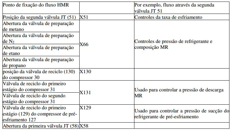
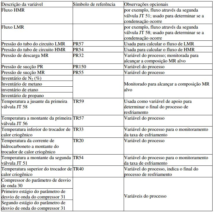
[00166] O processo automatizado para o resfriamento final do trocador de calor criogênico principal como descrito acima gradualmente reduziu a temperatura total do trocador de calor criogênico principal através da manipulação do fluxo de refrigerante misturado, a composição e a primeira e segunda válvulas JT que em parte determinam a relação de compressão intermitente através destas válvulas JT.[00166] The automated process for the final cooling of the main cryogenic heat exchanger as described above gradually reduced the total temperature of the main cryogenic heat exchanger by manipulating the mixed refrigerant flow, the composition and the first and second JT valves that in part determine the intermittent compression ratio through these JT valves.
[00167] Embora não aplicado no teste, foi contemplado ainda incorporar a estrutura do módulo da Fig. 6 (ou uma similar para outro alinhamento ou trocador de calor) em uma rede de módulo maior que compreende outros módulos precedentes, ou módulos subsequentes, ou ambos. Um exemplo de incorporação com módulos subsequentes é mostrado na figura. 7.[00167] Although not applied in the test, it was contemplated to still incorporate the module structure of Fig. 6 (or a similar one for another alignment or heat exchanger) in a larger module network comprising other previous modules, or subsequent modules, or both. An example of incorporation with subsequent modules is shown in the figure. 7.
[00168] A Fig. 7 mostra uma estrutura de módulo com algumas tarefas pós-resfriamento. Estas podem, por exemplo, ser tarefas intermediárias que necessitam ser completadas antes que um sistema automático de controle do processo para a operação normal possa assumir o controle. Por exemplo, o módulo 401 manipula a válvula degradada 44, com o objetivo de elevar o fluxo através do conduto 20 e 40 e da lateral do tubo de hidrocarboneto 29.[00168] Fig. 7 shows a module structure with some post-cooling tasks. These can, for example, be intermediate tasks that need to be completed before an automatic process control system for normal operation can take over. For example,
[00169] Outras variáveis manipuladas relevantes neste estágio incluem todas as variáveis manipuladas do estágio de resfriamento como descrito acima, acrescidas possivelmente do IGV e quaisquer válvulas de reciclo do compressor de refrigerante de pré-esfriamento que não foram incluídas como variável manipulada na automação do resfriamento.[00169] Other relevant manipulated variables at this stage include all the manipulated variables from the cooling stage as described above, possibly added by IGV and any pre-cooling refrigerant compressor recycling valves that were not included as a manipulated variable in the cooling automation. .
[00170] Preferivelmente, a manipulação de LMR e HMR é feita com base no controle de fluxo ao invés da abertura de válvula.[00170] Preferably, the handling of LMR and HMR is done based on flow control instead of valve opening.
[00171] Além disso, qualquer corrente de refluxo em uma extração de NGL em linha pode ser incluída como variável manipulada. No entanto, espera-se que o controle de nível normal possa assumir a direção após a taxa de alimentação de hidrocarboneto ter alcançado a sua faixa de operação normal.[00171] In addition, any reflux current in an online NGL extraction can be included as a manipulated variable. However, it is expected that normal level control can take over after the hydrocarbon feed rate has reached its normal operating range.
[00172] Outros módulos podem, portanto, estar em paralelo com o módulo 401. Como um exemplo, o módulo 402 foi representado, mas também poderia ser incluído um módulo para elevar qualquer seção de fracionamento que possa ser fornecida a jusante de qualquer coluna de extração de NLG para receber e ainda fracionar os líquidos de NLG extraídos. A pessoa de habilidade na técnica deve ser capaz de resolver quais variáveis manipuladas e controladas podem ser utilizadas, dependendo do tipo de alinhamento e equipamentos utilizados.[00172] Other modules can therefore be in parallel with
[00173] Os aparelhos e métodos aqui descritos podem ser aplicados aos trocadores térmicos criogênicos assim que um trocador de calor criogênico necessite ser resfriado antes da operação. Isto pode ser, por exemplo, o resfriamento inicial, ou o resfriamento após uma operação de manutenção ou após um erro: a razão pela qual o trocador era mais quente do que a temperatura de operação não é importante para a aplicação do assunto objeto aqui descrito.[00173] The devices and methods described here can be applied to cryogenic heat exchangers as soon as a cryogenic heat exchanger needs to be cooled before the operation. This can be, for example, the initial cooling, or the cooling after a maintenance operation or after an error: the reason why the exchanger was hotter than the operating temperature is not important for the application of the object described here .
[00174] A pessoa versada na técnica compreenderá que a presente invenção pode ser realizada de muitas maneiras diferentes, sem se afastar do escopo das reivindicações anexas. A invenção foi descrita com particularidade, incluindo a provisão de valores alvos para determinadas variáveis controladas. No entanto, será evidente para a pessoa versada na técnica que estes valores foram escolhidos em conexão com o alinhamento específico e equipamento utilizado para o teste. Tais detalhes podem necessitar de ser otimizados quando a invenção for realizada em outro alinhamento usando outro equipamento e, portanto, não devem ser considerados como limitativos do escopo da presente invenção.[00174] The person skilled in the art will understand that the present invention can be carried out in many different ways, without departing from the scope of the appended claims. The invention has been described with particularity, including the provision of target values for certain controlled variables. However, it will be evident to the person skilled in the art that these values were chosen in connection with the specific alignment and equipment used for the test. Such details may need to be optimized when the invention is carried out in another alignment using other equipment and, therefore, should not be considered as limiting the scope of the present invention.
Claims (17)
Applications Claiming Priority (3)
| Application Number | Priority Date | Filing Date | Title |
|---|---|---|---|
| EP08101424.3 | 2008-02-08 | ||
| EP08101424 | 2008-02-08 | ||
| PCT/EP2009/051353 WO2009098278A2 (en) | 2008-02-08 | 2009-02-06 | Method and apparatus for cooling down a cryogenic heat exchanger and method of liquefying a hydrocarbon stream |
Publications (3)
| Publication Number | Publication Date |
|---|---|
| BRPI0907488A2 BRPI0907488A2 (en) | 2015-07-14 |
| BRPI0907488B1 true BRPI0907488B1 (en) | 2020-08-04 |
| BRPI0907488B8 BRPI0907488B8 (en) | 2020-08-18 |
Family
ID=39628546
Family Applications (1)
| Application Number | Title | Priority Date | Filing Date |
|---|---|---|---|
| BRPI0907488A BRPI0907488B8 (en) | 2008-02-08 | 2009-02-06 | apparatus for cooling a cryogenic heat exchanger, method for cooling a cryogenic heat exchanger, and methods for liquefying a hydrocarbon stream |
Country Status (8)
| Country | Link |
|---|---|
| US (1) | US20100326133A1 (en) |
| KR (1) | KR20100120184A (en) |
| CN (1) | CN102405389B (en) |
| AU (1) | AU2009211380B2 (en) |
| BR (1) | BRPI0907488B8 (en) |
| MY (1) | MY155810A (en) |
| RU (1) | RU2495343C2 (en) |
| WO (1) | WO2009098278A2 (en) |
Families Citing this family (19)
| Publication number | Priority date | Publication date | Assignee | Title |
|---|---|---|---|---|
| RU2537483C2 (en) * | 2009-07-03 | 2015-01-10 | Шелл Интернэшнл Рисерч Маатсхаппий Б.В. | Procedure for cooled hydrocarbons flow making and device for its implementation |
| US8011191B2 (en) | 2009-09-30 | 2011-09-06 | Thermo Fisher Scientific (Asheville) Llc | Refrigeration system having a variable speed compressor |
| AU2013203120B2 (en) * | 2012-09-18 | 2014-09-04 | Woodside Energy Technologies Pty Ltd | Production of ethane for startup of an lng train |
| EP2857782A1 (en) | 2013-10-04 | 2015-04-08 | Shell International Research Maatschappij B.V. | Coil wound heat exchanger and method of cooling a process stream |
| US10240824B2 (en) * | 2013-10-15 | 2019-03-26 | Shell Oil Company | Method of monitoring an air operated heat exchanger and an air operated heat exchanger |
| US10765968B2 (en) | 2014-08-19 | 2020-09-08 | Supercritical Fluid Technologies, Inc. | Systems and methods for supercritical fluid chromatography |
| US11913685B2 (en) | 2014-08-19 | 2024-02-27 | Supercritical Fluid Technologies, Inc. | Cooling loop with a supercritical fluid system using compressed refrigerant fluid flow with a positive Joule Thomson coefficient |
| US10006588B2 (en) * | 2014-10-06 | 2018-06-26 | L'air Liquide Societe Anonyme Pour L'etude Et L'exploitation Des Procedes Georges Claude | Argon recondensing apparatus |
| RU2706892C2 (en) * | 2014-12-29 | 2019-11-21 | Шелл Интернэшнл Рисерч Маатсхаппий Б.В. | Cryogenic heat exchanger cooling method and device and hydrocarbon flow liquefaction method |
| AU2016227718B2 (en) | 2015-03-05 | 2018-07-05 | Shell Internationale Research Maatschappij B.V. | Methane oxidation catalyst, process to prepare the same and method of using the same |
| US10393429B2 (en) * | 2016-04-06 | 2019-08-27 | Air Products And Chemicals, Inc. | Method of operating natural gas liquefaction facility |
| PE20190556A1 (en) | 2016-07-26 | 2019-04-17 | Shell Int Research | METHOD AND APPARATUS FOR COOLING A CRIOGENIC HEAT EXCHANGER |
| PL3507008T3 (en) | 2016-08-31 | 2022-01-17 | Shell Internationale Research Maatschappij B.V. | Process to prepare a methane oxidation catalyst |
| CA3035129C (en) | 2016-08-31 | 2024-04-09 | Shell Internationale Research Maatschappij B.V. | Methane oxidation catalyst, process to prepare the same and method of using the same |
| WO2018071884A1 (en) * | 2016-10-14 | 2018-04-19 | Supercritical Fluid Technologies, Inc. | Cooling loop with a supercritical fluid system using compressed refrigerant fluid flow with a positive joule-thomson coefficient |
| CN106766670A (en) * | 2017-01-06 | 2017-05-31 | 四川杰瑞恒日天然气工程有限公司 | natural gas refrigeration system and method |
| AU2018321557B2 (en) * | 2017-08-24 | 2021-09-09 | Exxonmobil Upstream Research Company | Method and system for LNG production using standardized multi-shaft gas turbines, compressors and refrigerant systems |
| WO2020142753A1 (en) | 2019-01-04 | 2020-07-09 | Supercritical Fluid Technologies, Inc. | Interchangeable chromatography cartridge adapter system |
| US20220074654A1 (en) | 2020-09-04 | 2022-03-10 | Air Products And Chemicals, Inc. | Method to control the cooldown of main heat exchangers in liquefied natural gas plant |
Family Cites Families (21)
| Publication number | Priority date | Publication date | Assignee | Title |
|---|---|---|---|---|
| US4457768A (en) * | 1982-12-13 | 1984-07-03 | Phillips Petroleum Company | Control of a refrigeration process |
| US4809154A (en) * | 1986-07-10 | 1989-02-28 | Air Products And Chemicals, Inc. | Automated control system for a multicomponent refrigeration system |
| JPH04124582A (en) * | 1990-09-17 | 1992-04-24 | Hitachi Ltd | Chilled gas separating method and device for fluctuation of using amount of product gas |
| US5139548A (en) * | 1991-07-31 | 1992-08-18 | Air Products And Chemicals, Inc. | Gas liquefaction process control system |
| US5669238A (en) * | 1996-03-26 | 1997-09-23 | Phillips Petroleum Company | Heat exchanger controls for low temperature fluids |
| US5724833A (en) * | 1996-12-12 | 1998-03-10 | Phillips Petroleum Company | Control scheme for cryogenic condensation |
| US5791160A (en) * | 1997-07-24 | 1998-08-11 | Air Products And Chemicals, Inc. | Method and apparatus for regulatory control of production and temperature in a mixed refrigerant liquefied natural gas facility |
| JP3856538B2 (en) * | 1997-09-03 | 2006-12-13 | 日本エア・リキード株式会社 | Refrigeration equipment |
| DZ2671A1 (en) * | 1997-12-12 | 2003-03-22 | Shell Int Research | Liquefaction process of a gaseous fuel product rich in methane to obtain a liquefied natural gas. |
| US6220052B1 (en) * | 1999-08-17 | 2001-04-24 | Liberty Fuels, Inc. | Apparatus and method for liquefying natural gas for vehicular use |
| US7594414B2 (en) * | 2001-05-04 | 2009-09-29 | Battelle Energy Alliance, Llc | Apparatus for the liquefaction of natural gas and methods relating to same |
| EP1441836A4 (en) * | 2001-10-17 | 2006-04-19 | Praxair Technology Inc | Central carbon dioxide purifier |
| US6530240B1 (en) * | 2001-12-10 | 2003-03-11 | Gas Technology Institute | Control method for mixed refrigerant based natural gas liquefier |
| US6553772B1 (en) * | 2002-05-09 | 2003-04-29 | Praxair Technology, Inc. | Apparatus for controlling the operation of a cryogenic liquefier |
| US6631626B1 (en) * | 2002-08-12 | 2003-10-14 | Conocophillips Company | Natural gas liquefaction with improved nitrogen removal |
| TWI314637B (en) * | 2003-01-31 | 2009-09-11 | Shell Int Research | Process of liquefying a gaseous, methane-rich feed to obtain liquefied natural gas |
| DE102004028052A1 (en) * | 2004-06-09 | 2005-12-29 | Linde Ag | Process to liquefy natural gas by first-stage introduction of hydrocarbon-enriched fraction |
| US7866184B2 (en) * | 2004-06-16 | 2011-01-11 | Conocophillips Company | Semi-closed loop LNG process |
| US7213413B2 (en) * | 2004-06-16 | 2007-05-08 | Conocophillips Company | Noninvasive measurement and control system for use in hydrocarbon processing |
| EP2032921A2 (en) * | 2006-06-27 | 2009-03-11 | Fluor Technologies Corporation | Ethane recovery methods and configurations |
| US20090025422A1 (en) * | 2007-07-25 | 2009-01-29 | Air Products And Chemicals, Inc. | Controlling Liquefaction of Natural Gas |
-
2009
- 2009-02-06 BR BRPI0907488A patent/BRPI0907488B8/en active IP Right Grant
- 2009-02-06 RU RU2010137319/06A patent/RU2495343C2/en active
- 2009-02-06 AU AU2009211380A patent/AU2009211380B2/en active Active
- 2009-02-06 MY MYPI2010003314A patent/MY155810A/en unknown
- 2009-02-06 CN CN200980104368.XA patent/CN102405389B/en not_active Expired - Fee Related
- 2009-02-06 KR KR1020107019356A patent/KR20100120184A/en not_active Application Discontinuation
- 2009-02-06 US US12/866,080 patent/US20100326133A1/en not_active Abandoned
- 2009-02-06 WO PCT/EP2009/051353 patent/WO2009098278A2/en active Application Filing
Also Published As
| Publication number | Publication date |
|---|---|
| WO2009098278A2 (en) | 2009-08-13 |
| AU2009211380B2 (en) | 2012-05-03 |
| RU2010137319A (en) | 2012-03-20 |
| BRPI0907488B8 (en) | 2020-08-18 |
| AU2009211380A1 (en) | 2009-08-13 |
| CN102405389B (en) | 2014-12-03 |
| MY155810A (en) | 2015-11-30 |
| US20100326133A1 (en) | 2010-12-30 |
| RU2495343C2 (en) | 2013-10-10 |
| KR20100120184A (en) | 2010-11-12 |
| BRPI0907488A2 (en) | 2015-07-14 |
| WO2009098278A3 (en) | 2014-10-02 |
| CN102405389A (en) | 2012-04-04 |
Similar Documents
| Publication | Publication Date | Title |
|---|---|---|
| BRPI0907488B1 (en) | APPLIANCE FOR COOLING A CRYOGENIC HEAT EXCHANGER, METHOD FOR COOLING A CRYOGENIC HEAT EXCHANGER, AND METHODS FOR LIQUEFACING A HYDROCARBON CHAIN | |
| US20210278130A1 (en) | Method and apparatus for cooling down a cryogenic heat exchanger and method of liquefying a hydrocarbon stream | |
| CA2963210C (en) | Method of operating natural gas liquefaction facility | |
| BRPI0814619B1 (en) | METHOD AND APPARATUS FOR COOLING A HYDROCARBON CURRENT AND METHOD AND APPARATUS FOR COOLING A MIXED COOL CURRENT | |
| WO2009050175A1 (en) | Method and apparatus for controlling a refrigerant compressor, and use thereof in a method of cooling a hydrocarbon stream | |
| BRPI1013712B1 (en) | method for liquefying a hydrocarbon-rich fraction | |
| WO2012125018A1 (en) | A method and system for controlling the temperature of liquefied natural gas in a liquefaction process | |
| NL2015933B1 (en) | Method and system for producing a cooled hydrocarbons stream. | |
| AU2021225175B2 (en) | Method to control the cooldown of main heat exchangers in liquefied natural gas plant | |
| KR20240024823A (en) | Method and system for preventing freezing of at least one component of cryogenic fluid within a cryogenic heat exchanger |
Legal Events
| Date | Code | Title | Description |
|---|---|---|---|
| B06F | Objections, documents and/or translations needed after an examination request according [chapter 6.6 patent gazette] | ||
| B06T | Formal requirements before examination [chapter 6.20 patent gazette] | ||
| B06A | Patent application procedure suspended [chapter 6.1 patent gazette] | ||
| B09A | Decision: intention to grant [chapter 9.1 patent gazette] | ||
| B16A | Patent or certificate of addition of invention granted [chapter 16.1 patent gazette] |
Free format text: PRAZO DE VALIDADE: 10 (DEZ) ANOS CONTADOS A PARTIR DE 04/08/2020, OBSERVADAS AS CONDICOES LEGAIS. |
|
| B16C | Correction of notification of the grant [chapter 16.3 patent gazette] |
Free format text: REF. RPI 2587 DE 04/08/2020 QUANTO AO TITULAR. |