BRPI0901007B1 - FLEXIBLE TUBE JOINTS - Google Patents
FLEXIBLE TUBE JOINTS Download PDFInfo
- Publication number
- BRPI0901007B1 BRPI0901007B1 BRPI0901007-6A BRPI0901007A BRPI0901007B1 BR PI0901007 B1 BRPI0901007 B1 BR PI0901007B1 BR PI0901007 A BRPI0901007 A BR PI0901007A BR PI0901007 B1 BRPI0901007 B1 BR PI0901007B1
- Authority
- BR
- Brazil
- Prior art keywords
- housing
- flexible
- flexible element
- tube
- extension tube
- Prior art date
Links
- 230000009975 flexible effect Effects 0.000 title claims abstract description 595
- 230000006835 compression Effects 0.000 claims abstract description 20
- 238000007906 compression Methods 0.000 claims abstract description 20
- 238000006073 displacement reaction Methods 0.000 claims description 69
- 229920001971 elastomer Polymers 0.000 claims description 28
- 239000000806 elastomer Substances 0.000 claims description 26
- 230000004308 accommodation Effects 0.000 claims description 2
- 239000012530 fluid Substances 0.000 abstract description 39
- 238000002955 isolation Methods 0.000 abstract description 24
- 239000000203 mixture Substances 0.000 abstract description 11
- 238000004519 manufacturing process Methods 0.000 description 29
- 230000004888 barrier function Effects 0.000 description 9
- 238000007667 floating Methods 0.000 description 9
- 238000010276 construction Methods 0.000 description 8
- 238000000465 moulding Methods 0.000 description 8
- 210000002435 tendon Anatomy 0.000 description 8
- 238000009413 insulation Methods 0.000 description 5
- XEEYBQQBJWHFJM-UHFFFAOYSA-N iron Substances [Fe] XEEYBQQBJWHFJM-UHFFFAOYSA-N 0.000 description 5
- PXHVJJICTQNCMI-UHFFFAOYSA-N Nickel Chemical compound [Ni] PXHVJJICTQNCMI-UHFFFAOYSA-N 0.000 description 4
- 238000009434 installation Methods 0.000 description 4
- 229910052751 metal Inorganic materials 0.000 description 4
- 239000002184 metal Substances 0.000 description 4
- 238000000034 method Methods 0.000 description 4
- 239000004696 Poly ether ether ketone Substances 0.000 description 3
- DNIAPMSPPWPWGF-UHFFFAOYSA-N Propylene glycol Chemical compound CC(O)CO DNIAPMSPPWPWGF-UHFFFAOYSA-N 0.000 description 3
- 238000001816 cooling Methods 0.000 description 3
- 238000013461 design Methods 0.000 description 3
- 238000005553 drilling Methods 0.000 description 3
- 229910052742 iron Inorganic materials 0.000 description 3
- 239000000463 material Substances 0.000 description 3
- 230000004048 modification Effects 0.000 description 3
- 238000012986 modification Methods 0.000 description 3
- 229920002530 polyetherether ketone Polymers 0.000 description 3
- 230000008569 process Effects 0.000 description 3
- 238000007789 sealing Methods 0.000 description 3
- 229910000679 solder Inorganic materials 0.000 description 3
- 229910000851 Alloy steel Inorganic materials 0.000 description 2
- VYZAMTAEIAYCRO-UHFFFAOYSA-N Chromium Chemical compound [Cr] VYZAMTAEIAYCRO-UHFFFAOYSA-N 0.000 description 2
- 229910052804 chromium Inorganic materials 0.000 description 2
- 239000011651 chromium Substances 0.000 description 2
- 238000005260 corrosion Methods 0.000 description 2
- 230000007797 corrosion Effects 0.000 description 2
- 229910052759 nickel Inorganic materials 0.000 description 2
- 238000007493 shaping process Methods 0.000 description 2
- 238000004513 sizing Methods 0.000 description 2
- XLYOFNOQVPJJNP-UHFFFAOYSA-N water Substances O XLYOFNOQVPJJNP-UHFFFAOYSA-N 0.000 description 2
- -1 76% nickel Chemical compound 0.000 description 1
- 229910000599 Cr alloy Inorganic materials 0.000 description 1
- 230000003466 anti-cipated effect Effects 0.000 description 1
- 230000000712 assembly Effects 0.000 description 1
- 238000000429 assembly Methods 0.000 description 1
- JUPQTSLXMOCDHR-UHFFFAOYSA-N benzene-1,4-diol;bis(4-fluorophenyl)methanone Chemical compound OC1=CC=C(O)C=C1.C1=CC(F)=CC=C1C(=O)C1=CC=C(F)C=C1 JUPQTSLXMOCDHR-UHFFFAOYSA-N 0.000 description 1
- 230000005540 biological transmission Effects 0.000 description 1
- 230000008859 change Effects 0.000 description 1
- 239000000788 chromium alloy Substances 0.000 description 1
- BIJOYKCOMBZXAE-UHFFFAOYSA-N chromium iron nickel Chemical compound [Cr].[Fe].[Ni] BIJOYKCOMBZXAE-UHFFFAOYSA-N 0.000 description 1
- 229910017052 cobalt Inorganic materials 0.000 description 1
- 239000010941 cobalt Substances 0.000 description 1
- GUTLYIVDDKVIGB-UHFFFAOYSA-N cobalt atom Chemical compound [Co] GUTLYIVDDKVIGB-UHFFFAOYSA-N 0.000 description 1
- 238000002485 combustion reaction Methods 0.000 description 1
- 230000000295 complement effect Effects 0.000 description 1
- 238000001514 detection method Methods 0.000 description 1
- 238000010586 diagram Methods 0.000 description 1
- 239000013536 elastomeric material Substances 0.000 description 1
- 230000007613 environmental effect Effects 0.000 description 1
- 230000001747 exhibiting effect Effects 0.000 description 1
- 238000010438 heat treatment Methods 0.000 description 1
- 229930195733 hydrocarbon Natural products 0.000 description 1
- 150000002430 hydrocarbons Chemical class 0.000 description 1
- 238000005304 joining Methods 0.000 description 1
- 238000005259 measurement Methods 0.000 description 1
- 230000007246 mechanism Effects 0.000 description 1
- 239000012528 membrane Substances 0.000 description 1
- 239000006082 mold release agent Substances 0.000 description 1
- 229910000623 nickel–chromium alloy Inorganic materials 0.000 description 1
- 229920001515 polyalkylene glycol Polymers 0.000 description 1
- 238000009824 pressure lamination Methods 0.000 description 1
- 230000009467 reduction Effects 0.000 description 1
- 239000013535 sea water Substances 0.000 description 1
- 239000007787 solid Substances 0.000 description 1
- 238000003860 storage Methods 0.000 description 1
- 229920001169 thermoplastic Polymers 0.000 description 1
- 239000004416 thermosoftening plastic Substances 0.000 description 1
- 238000003466 welding Methods 0.000 description 1
Images


Classifications
-
- F—MECHANICAL ENGINEERING; LIGHTING; HEATING; WEAPONS; BLASTING
- F16—ENGINEERING ELEMENTS AND UNITS; GENERAL MEASURES FOR PRODUCING AND MAINTAINING EFFECTIVE FUNCTIONING OF MACHINES OR INSTALLATIONS; THERMAL INSULATION IN GENERAL
- F16L—PIPES; JOINTS OR FITTINGS FOR PIPES; SUPPORTS FOR PIPES, CABLES OR PROTECTIVE TUBING; MEANS FOR THERMAL INSULATION IN GENERAL
- F16L27/00—Adjustable joints, Joints allowing movement
- F16L27/10—Adjustable joints, Joints allowing movement comprising a flexible connection only, e.g. for damping vibrations
- F16L27/103—Adjustable joints, Joints allowing movement comprising a flexible connection only, e.g. for damping vibrations in which a flexible element, e.g. a rubber-metal laminate, which undergoes constraints consisting of shear and flexure, is sandwiched between partly curved surfaces
-
- E—FIXED CONSTRUCTIONS
- E21—EARTH DRILLING; MINING
- E21B—EARTH DRILLING, e.g. DEEP DRILLING; OBTAINING OIL, GAS, WATER, SOLUBLE OR MELTABLE MATERIALS OR A SLURRY OF MINERALS FROM WELLS
- E21B17/00—Drilling rods or pipes; Flexible drill strings; Kellies; Drill collars; Sucker rods; Cables; Casings; Tubings
- E21B17/02—Couplings; joints
- E21B17/08—Casing joints
- E21B17/085—Riser connections
Abstract
sistema de isolamento de pressão para juntas de tubo flexíveis uma junta de tubo flexível em dois elementos flexíveis elastoméricos anulares empilhados de maneira coaxial em um raio interno a partir de um centro de rotação comum, e pelo menos um elementos flexível elastomérico disposto em um raio externo a partir do centro de rotação comum. os elementos flexíveis no raio interno são acoplados mecanicamente em séria entre o tubo de extensão e a carcaça da junta de tubo flexível, e o elemento flexível no raio externo é acoplado mecanicamente em paralelo com a combinação em série dos elementos flexíveis internos. os elementos flexíveis internos isolam o elemento flexível no raio externo do fluido de transporte, e o elemento flexível no raio externo reduz a compressão axial dos elementos flexíveis internos. assim, os elementos flexíveis internos podem ter um raio reduzido e uma composição diferente para lidar com uma carga mais elevada de pressão e pressão.pressure isolation system for flexible pipe joints a flexible pipe joint in two annular flexible elastomeric elements stacked coaxially on an inner radius from a common center of rotation, and at least one elastomeric flexible element arranged on an outer radius from the common center of rotation. the flexible elements on the inner radius are mechanically coupled in series between the extension tube and the hose joint housing, and the flexible element on the outer radius is mechanically coupled in parallel with the series combination of the inner flexible elements. the inner flexible elements insulate the flexible element in the outer radius from the transport fluid, and the flexible element in the outer radius reduces axial compression of the inner flexible elements. thus, the internal flexible elements can have a reduced radius and a different composition to handle a higher pressure and pressure load.
Description
[001] A presente invenção refere-se a uma junta de tubo flexível que tem um tubo de extensão que se estende a partir de um alojamento e pelo menos um elemento flexível elastomérico anular para montar o tubo de extensão no alojamento para permitir o deslocamento angular do tubo de extensão com relação ao alojamento.[001] The present invention relates to a flexible tube joint having an extension tube extending from a housing and at least one annular elastomeric flexible element for mounting the extension tube in the housing to allow angular displacement of the extension tube with respect to the housing.
[002] Juntas flexíveis que têm um elemento flexível elastomérico anular que monta uma extensão em um alojamento são usadas para reduzir as tensões induzidas pelo movimento entre instalações offshore flutuantes e tubos ascendentes e tendões que pendem das instalações offshore flutuantes. Tipicamente, o elemento flexível consiste em calços de metal esféricos alternados, ou em outro material rígido, e em camadas de material elastomérico. Tal elemento flexível é capaz de apresentar um deslocamento angular livre de cerca de 15 graus ou mais enquanto suporta uma tensão axial proporcional ao tamanho do elemento flexível. Tipicamente, o tamanho do elemento flexível foi selecionado para lidar com a carga desejada sobre o tubo ascendente ou tendão, e os elementos flexíveis foram fabricados e estocados em diversos tamanhos para lidar com diversos tamanhos padrões de tubos ascendentes ou tendões.[002] Flexible joints that have an annular elastomeric flexible element that mounts an extension in a housing are used to reduce the stresses induced by movement between floating offshore installations and risers and tendons that hang from the floating offshore installations. Typically, the flexible element consists of alternating spherical metal shims, or other rigid material, and layers of elastomeric material. Such a flexible element is capable of exhibiting a free angular displacement of about 15 degrees or more while bearing an axial tension proportional to the size of the flexible element. Typically, the flexible element size was selected to handle the desired load on the riser or tendon, and the flexible elements were manufactured and stocked in various sizes to handle various standard sizes of risers or tendons.
[003] Tubos ascendentes são utilizados para transferência de fluidos de produção do leito marinho até o convés de uma embarcação offshore flutuante e para transferência do fluido de produção fora da embarcação para uma ou mais linhas de exportação. As cargas impressas pelo tubo ascendente sobre um elemento flexível consistem tipicamente na tensão no tubo ascendente, no deslocamento angular e na rotação do tubo ascendente, na pressão interna no fluido de produção e no aumento da temperatura do fluido de produção. Assim, a pressão interna no fluido de produção e o aumento da temperatura do fluido de produção podem tornar a seleção de um elemento flexível para um tubo ascendente mais difícil que a seleção de um elemento flexível para um tendão.[003] Riser pipes are used for transferring production fluids from the seabed to the deck of a floating offshore vessel and for transferring production fluid off the vessel to one or more export lines. The loads printed by the riser on a flexible element typically consist of the tension in the riser, the angular displacement and rotation of the riser, the internal pressure in the production fluid, and the increase in the temperature of the production fluid. Thus, the internal pressure in the production fluid and the increasing temperature of the production fluid can make selecting a flexible element for a riser more difficult than selecting a flexible element for a tendon.
[004] Em diversas aplicações, juntas de tubo flexíveis têm incorporado mais de um elemento flexível em um alojamento comum. Por exemplo, uma junta de tubo flexível de duas extremidades para um tubo ascendente tem um primeiro elemento flexível no alojamento para montar um primeiro tubo de extensão no alojamento e um segundo elemento flexível no alojamento para montar um segundo tubo de extensão no alojamento. Os dois tubos de extensão estendem-se em direções opostas a partir do alojamento comum. Desta maneira, a junta de tubo flexível de duas extremidades pode acomodar duas vezes o deslocamento angular que pode ser tolerado por uma junta de tubo flexível de extremidade única que tenha um único elementoflexível. O deslocamento angular é dividido entre os dois elementos flexíveis na junta de tubo flexível de duas extremidades, mas cada um dos dois elementos flexíveis porta a mesma tensão total do tubo ascendente. Exemplos de tais juntas de tubo flexíveis de duas extremidades são encontrados na patente norte-americana 3 680 895, de Herbert et alii,emitida em 1o de agosto de 1972; na patente norte- americana 4 068 864, de Herbert et alii, emitida em 17 de janeiro de 1978 (ver a Figura 4); e na patente norte-americana 5 133 578, de Whightsil, Sr. et alii, emitida em 28 de julho de 1992.[004] In many applications, flexible pipe joints have incorporated more than one flexible element into a common housing. For example, a double ended flexible tube joint for a riser has a first flexible element in the housing to mount a first extension tube in the housing and a second flexible element in the housing to mount a second extension tube in the housing. The two extension tubes extend in opposite directions from the common housing. In this way, the double-ended flex-tube joint can accommodate twice the angular displacement that can be tolerated by a single-ended flex-tube joint having a single flexible element. The angular displacement is divided between the two flexible elements in the double-ended flexible pipe joint, but each of the two flexible elements carries the same total tension of the riser. Examples of such double-ended flexible pipe joints are found in U.S. Patent 3,680,895, to Herbert et al, issued August 1, 1972; U.S. Patent 4,068,864, to Herbert et al, issued January 17, 1978 (see Figure 4); and U.S. Patent 5,133,578, to Whightsil, Sr. et al, issued July 28, 1992.
[005] As juntas de tubo flexíveis têm incorporado mais de um elemento flexível em um alojamento comum, de modo que dois elementos flexíveis são submetidos ao mesmo deslocamento angular, ainda que apenas um destes dois elementos flexíveis porte a carga de tração sobre a junta de tubo flexível. Tal disposição pode reduzir a pressão do fluido de produção sobre cada elemento flexível e proporcionar um mecanismo de vedação tanto primário quanto sobressalente para conter o fluido de produção pressurizado dentro da junta de tubo. Entretanto, não é necessário que os elementos flexíveis de acordo com estes conceitos sejam pré-comprimidas para funcionamento apropriado; um fato que reduz a vida útil dos elementos flexíveis. Assim, estes desenhos fazem um uso ineficaz dos dois elementos flexíveis tanto para portar a carga axial sobre o tubo quanto para vedar a pressão. Exemplos de tais jun tas de tubo flexíveis são encontrados na patente norte-americana 4 183 556, de Schwemmer, emitida em 15 de janeiro de 1980; na patente norte-americana 4 068 868, de Ohrt, emitida em 17 de janeiro de 1978; na patente norte-americana 4 784 410, de Peppel et alii, emitida em 15 de novembro de 1988; e na patente norte- americana 4 984 827, de Peppel et alii, emitida em 15 de janeiro de 1991.[005] Flexible pipe joints have incorporated more than one flexible element in a common housing, so that two flexible elements are subjected to the same angular displacement, even though only one of these two flexible elements carries the tensile load on the joint. flexible tube. Such an arrangement can reduce the pressure of the production fluid on each flexible element and provide both a primary and a spare sealing mechanism to contain the pressurized production fluid within the pipe joint. However, it is not necessary that the flexible elements according to these concepts be pre-compressed for proper functioning; a fact that reduces the service life of the flexible elements. Thus, these designs make ineffective use of the two flexible elements both to carry the axial load on the pipe and to seal off the pressure. Examples of such flexible tube joints are found in U.S. Patent 4,183,556, to Schwemmer, issued January 15, 1980; U.S. Patent 4,068,868, to Ohrt, issued January 17, 1978; U.S. Patent 4,784,410, to Peppel et al, issued November 15, 1988; and U.S. Patent 4,984,827, to Peppel et al, issued January 15, 1991.
[006] Uma junta de tubo com dois elementos flexíveis em um alojamento comum e diferentes níveis de pré-compressão axial sobre os dois elementos é revelada na patente norte-americana 4 416 473, de Lamy et alii, emitida em 23 de no-vembro de 1983. Os dois elementos flexíveis são dispostos em lados opostos de um centro de rotação comum. A junta de tubo tem um flange e uma gola que formam um mancal esférico que permite o deslocamento angular, mas impede o movimento re-lativo sob compressão axial. (Lamy, col. 5, linhas 2-8). Um elemento flexível com um diâmetro maior assume cargas de tração axiais. O outro elemento flexível com um diâmetro menor é projetado de modo a assegurar unicamente a vedação do fluido dentro do tubo. (Lamy, col. 5, linhas 16-34). Uma pré-tensão axial desejada é aplicada ao elemento flexível que tem o menor diâmetro por cavilhas de tração até ficar mais apertado, de modo a fechar a folga de uma abertura cilíndrica (Lamy, col. 6, linhas 30-46).[006] A pipe joint with two flexible elements in a common housing and different levels of axial precompression on the two elements is disclosed in U.S. Patent 4,416,473, to Lamy et alii, issued on November 23 1983. The two flexible elements are arranged on opposite sides of a common center of rotation. The pipe joint has a flange and collar that form a spherical bearing that allows angular displacement but prevents relative movement under axial compression. (Lamy, col. 5, lines 2-8). A flexible element with a larger diameter assumes axial tensile loads. The other flexible element with a smaller diameter is designed so as to only ensure the sealing of the fluid inside the tube. (Lamy, col. 5, lines 16-34). A desired axial pre-strain is applied to the flexible element having the smallest diameter by pulling pins until tighter so as to close the gap of a cylindrical opening (Lamy, col. 6, lines 30-46).
[007] Para lidar com a alta pressão do fluido dentro de uma junta de tubo flexível, é desejável que a junta de tubo flexível inclua pelo menos um elemento flexível elastomérico primário para lidar com cargas axiais sobre a junta de tubo e pelo menos um elemento flexível elastomérico secundário especialmente projetado para conter a pressão de fluido dentro da junta de tubo flexível e reduzir ou eliminar a pressão do fluido sobre o elemento flexível primário. Pela redução ou eliminação da pressão do fluido sobre o elemento flexível primário, o tamanho do elemento flexível primário pode ser reduzido, e seu tempo de vida útil pode ser prolongado. Entretanto, uma redução no tamanho do elemento flexível primário não deve exigir um aumento significativo no tamanho total da junta flexível para acomodação do elemento flexível elastomérico secundário. Portanto, é desejável obter elementos flexíveis secundários mais compactos mais adequados para configurações de junta de tubo flexível específicas.[007] To handle high fluid pressure within a flexible pipe joint, it is desirable that the flexible pipe joint include at least one primary elastomeric flexible element to handle axial loads on the pipe joint and at least one element secondary elastomeric hose specially designed to contain fluid pressure within the hose joint and reduce or eliminate fluid pressure on the primary flexible element. By reducing or eliminating fluid pressure on the primary flexible element, the size of the primary flexible element can be reduced, and its service life extended. However, a reduction in the size of the primary flexible element should not require a significant increase in the overall flexible joint size to accommodate the secondary elastomeric flexible element. Therefore, it is desirable to obtain more compact secondary flexible elements more suitable for specific flexible pipe joint configurations.
[008] Há diversas configurações de junta de tubo flexível que têm uma faixa limitada de deslocamento axial para seu uso pretendido. Esta faixa limitada de deslocamento axial pode ser devida à configuração de junta de tubo flexível específica ou devida ao uso específico da junta de tubo flexível. Muito frequentemente, a faixa limitada de deslocamento axial é compatível com um elemento flexível secundário projetado especialmente para conter a pressão do fluido de modo que o elemento flexível secundário não seja submetido a um deslocamento axial excessivo. Neste caso, é desejável obter um sistema de isolamento de pressão muito compacto que possa ser montado facilmente na configuração de junta de tubo flexível sem modificação substancial da configuração de junta de tubo flexível. Portanto, é possível aumentar a capacidade de lidar com a carga ou o tempo de vida útil de diversos tipos de configuração de junta de tubo flexível.[008] There are several flexible pipe joint configurations that have a limited range of axial displacement for their intended use. This limited range of axial displacement may be due to the specific flex-tube joint configuration or due to the specific use of the flex-tube joint. Very often, the limited range of axial displacement is compatible with a secondary flexible element specially designed to contain fluid pressure so that the secondary flexible element is not subjected to excessive axial displacement. In this case, it is desirable to obtain a very compact pressure isolation system that can be easily fitted to the flexible pipe joint configuration without substantial modification of the flexible pipe joint configuration. Therefore, it is possible to increase the capacity to handle the load or the service life of different types of flexible pipe joint configurations.
[009] É também desejável obter uma configuração de junta de tubo flexível especialmente projetada para acomodar elementos flexíveis secundários. Tal configuração de junta de tubo flexível pode lidar com uma pressão, temperatura e cargas axiais mais elevadas para uma dada vida útil de serviço e um dado tamanho do alojamento ou pegada do alojamento.[009] It is also desirable to obtain a specially designed flexible pipe joint configuration to accommodate secondary flexible elements. Such a flexible pipe joint configuration can handle higher pressure, temperature and axial loads for a given service life and a given housing size or housing footprint.
[010] De acordo com um primeiro aspecto, a invenção apresenta uma junta de tubo flexível que inclui um alojamento, um tubo de extensão que se estende a partir do alojamento, um primeiro elemento flexível elastomérico anular disposto no alojamento, um segundo elemento flexível elastomérico anular disposto no alojamento e um terceiro elemento flexível elastomérico anular disposto no alojamento. Os primeiro, segundo e terceiro elementos flexíveis têm um centro de rotação comum, os primeiro e segundo elementos flexíveis são empilhados de maneira coaxial em lados opostos do centro de rotação comum, os primeiro e segundo elementos flexíveis são dispostos a partir do centro de rotação comum por um raio interno co mum e o terceiro elemento flexível é disposto a partir do centro de rotação comum por um raio externo maior que o raio interno. Os primeiro e segundo elementos flexíveissão mecanicamente unidos em série entre o alojamento e o tubo de extensão, e o terceiro elemento flexível é mecanicamente unido ao alojamento e ao tubo de extensão em paralelo com a combinação em série dos primeiro e segundo elementos flexíveis.[010] According to a first aspect, the invention features a flexible tube joint that includes a housing, an extension tube extending from the housing, a first annular elastomeric flexible element disposed in the housing, a second elastomeric flexible element an annular flexible element disposed in the housing and a third annular flexible elastomeric element disposed in the housing. The first, second and third flexible elements have a common center of rotation, the first and second flexible elements are stacked coaxially on opposite sides of the common center of rotation, the first and second flexible elements are arranged from the common center of rotation by a common inner radius and the third flexible element is arranged from the common center of rotation by an outer radius greater than the inner radius. The first and second flexible elements are mechanically joined in series between the housing and the extension tube, and the third flexible element is mechanically joined to the housing and the extension tube in parallel with the series combination of the first and second flexible elements.
[011] De acordo com um segundo aspecto, a invenção apresenta uma junta de tubo flexível que inclui um alojamento que tem uma primeira extremidade e uma segunda extremidade, um flange de fixação montado na primeira extremidade do alojamento, um tubo de extensão que se estende a partir da segunda extremidade do alojamento e um tubo interno disposto dentro do alojamento e montado no flange de fixação e que proporciona um canal de uma abertura no flange de fixação até o tubo de extensão. O tubo de extensão tem um flange externo e um invólucro externo. A junta de tubo flexível inclui também um anel centralizador disposto dentro do alojamento, e o tubo interno tem um flange dentro do anel centralizador, e o flange interno do tubo de extensão é disposto dentro do anel centralizador. Uma parte do anel centralizador é disposta entre o flange interno do tubo de extensão e o invólucro do tubo de extensão. A junta de tubo flexível inclui também um primeiro elemento flexível elastomérico anular disposto dentro do alojamento entre o anel centralizador e o flange interno do tubo de extensão, um segundo elemento flexível elastomérico anular disposto dentro do alojamento entre o anel centralizador e o flange do tubo interno, e um terceiro elemento flexível elastomérico anular disposto dentro do alojamento entre o alojamento e o invólucro externo do tubo de extensão para montar o tubo de extensão no alojamento para o deslocamento angular do tubo de extensão com relação ao alojamento. O tubo de extensão passa através do terceiro elemento flexível de modo que o terceiro elemento flexível circunde o tubo de extensão. O anel centralizador acopla os primeiro e segundo elementos flexíveis mecanicamente em série entre o tubo de extensão e o alojamento, de modo que o deslocamento angular do tubo de extensão com relação ao alojamento provoque um deslocamento angular do anel centralizador com relação ao alojamento que é cerca da metade do deslocamento angular do tubo de extensão com relação ao alojamento e a tensão axial sobre o tubo de extensão com relação ao alojamento ponha cada um dos pri-meiro, segundo e terceiro elementos flexíveis em compressão.[011] According to a second aspect, the invention features a flexible tube joint that includes a housing having a first end and a second end, a fastening flange mounted on the first end of the housing, an extension tube that extends from the second end of the housing and an inner tube disposed within the housing and mounted to the clamping flange and providing a channel from an opening in the clamping flange to the extension tube. The extension tube has an outer flange and an outer shell. The flexible tube joint also includes a centering ring disposed within the housing, and the inner tube has a flange within the centering ring, and the inner flange of the extension tube is disposed within the centering ring. A portion of the centering ring is disposed between the extension tube inner flange and the extension tube housing. The flexible tube joint also includes a first annular elastomeric flexible element disposed within the housing between the centering ring and the inner tube flange, a second annular elastomeric flexible element disposed within the housing between the centering ring and the inner tube flange , and a third annular elastomeric flexible element disposed within the housing between the housing and the extension tube outer shell for mounting the extension tube to the housing for angular displacement of the extension tube relative to the housing. The extension tube passes through the third flexible element so that the third flexible element surrounds the extension tube. The centering ring couples the first and second flexible elements mechanically in series between the extension tube and the housing, so that the angular displacement of the extension tube with respect to the housing causes an angular displacement of the centering ring with respect to the surrounding housing. half the angular displacement of the extension tube with respect to the housing and the axial tension on the extension tube with respect to the housing put each of the first, second, and third flexible elements in compression.
[012] De acordo com um terceiro aspecto, a invenção apresenta uma junta de tubo flexível que inclui um alojamento que tem uma primeira extremidade e uma segunda extremidade, um flange de fixação montado na primeira extremidade do alojamento, um anel de sustentação montado na segunda extremidade do alojamento, um tubo de extensão que se estende a partir da segunda extremidade do alojamento e um tubo interno disposto dentro do alojamento e soldado no flange de fixação e que proporciona um canal de uma abertura no flange de fixação até o tubo de extensão. A junta de tubo flexível inclui também um anel centralizador esférico disposto dentro do alojamento. O tubo de extensão tem um flange interno e um invólucro externo, e o tubo interno tem um flange interno e um invólucro externo. O flange interno do tubo de extensão é disposto dentro do anel centralizador, e o flange interno do tubo interno é disposto dentro do anel centralizador. A junta de tubo flexível inclui também um primeiro elemento flexível elastomérico anular disposto dentro do alojamento entre o anel centralizador e o flange interno do tubo de extensão, e o elastômero do primeiro elemento flexível é ligado ao anel centralizador e ligado ao flange interno do tubo de extensão. A junta de tubo flexível inclui também um segundo elemento flexível elastomérico anular disposto dentro do alojamento entre o anel centralizador e o flange interno do tubo interno, e o elastômero do segundo elemento flexível é ligado ao anel centralizador e ligado ao flange interno do tubo interno. A junta de tubo flexível inclui também um terceiro elemento flexível elastomérico anular disposto dentro do alojamento entre o anel de sustentação e o invólucro externo do tubo de extensão, e o elastômero do terceiro elemento flexível é ligado ao anel de sustentação e ligado ao invólucro externo do tubo de extensão. O terceiro elemento flexível monta o tubo de extensão no alojamento para deslocamento angular do tubo de extensão com relação ao alojamento, e o tubo de extensão passa através do ter- ceiro elemento flexível de modo que o terceiro elemento flexível circunde o tubo de extensão. A junta de tubo flexível inclui também um anel de carga preso ao invólucro externo do tubo de extensão e um quarto elemento flexível elastomérico anular disposto dentro do alojamento entre o anel de carga e o invólucro externo do tubo interno. O elastômero do quarto elemento flexível é ligado ao anel de carga e ligado ao invólucro externo do tubo interno, e o tubo interno passa através do quarto elementoflexível de modo que o quarto elemento flexível circunde o tubo interno.[012] According to a third aspect, the invention features a flexible tube joint that includes a housing that has a first end and a second end, a fastening flange mounted on the first end of the housing, a support ring mounted on the second end of the housing, an extension tube extending from the second end of the housing and an inner tube disposed within the housing and welded to the attachment flange and providing a channel from an opening in the attachment flange to the extension tube. The flexible tube joint also includes a spherical centering ring disposed within the housing. The extension tube has an inner flange and an outer shell, and the inner tube has an inner flange and an outer shell. The inner flange of the extension tube is disposed within the centering ring, and the inner flange of the inner tube is disposed within the centering ring. The flexible tube joint also includes a first annular elastomeric flexible element disposed within the housing between the centering ring and the inner flange of the extension tube, and the elastomer of the first flexible element is connected to the centering ring and connected to the inner flange of the extension tube. extension. The flexible tube joint also includes a second annular elastomeric flexible element disposed within the housing between the centering ring and the inner flange of the inner tube, and the elastomer of the second flexible element is connected to the centering ring and connected to the inner flange of the inner tube. The flexible tube joint also includes a third annular elastomeric flexible element disposed within the housing between the support ring and the outer shell of the extension tube, and the elastomer of the third flexible element is connected to the support ring and connected to the outer shell of the extension tube. extension tube. The third flexible element mounts the extension tube in the housing for angular displacement of the extension tube with respect to the housing, and the extension tube passes through the third flexible element so that the third flexible element surrounds the extension tube. The flexible tube joint also includes a load ring secured to the outer shell of the extension tube and a fourth annular elastomeric flexible element disposed within the housing between the load ring and the outer shell of the inner tube. The elastomer of the fourth flexible element is connected to the load ring and connected to the outer shell of the inner tube, and the inner tube passes through the fourth flexible element so that the fourth flexible element surrounds the inner tube.
[013] De acordo com um quarto aspecto, a invenção apresenta uma junta de tubo flexível que inclui um alojamento, um flange de fixação montado na primeira extremidade do alojamento, um anel de sustentação montado na segunda extremidade no alojamento, um tubo interno fixado no flange de fixação e um tubo de extensão que se estende a partir da segunda extremidade do alojamento. A junta de tubo flexível inclui também um primeiro revestimento interno disposto no e soldado ao tubo interno, um segundo revestimento interno disposto no e soldado ao tubo de extensão, um anel centralizador, um primeiro elemento flexível elastomérico anular disposto no alojamento e montado entre o primeiro revestimento interno e o anel centralizador, um segundo elemento flexível elastomérico anular disposto no alojamento e montado entre o segundo revestimento interno e o anel centralizador, e um terceiro elemento flexível elastomérico anular disposto no alojamento e montado entre o tubo de extensão e o anel de sustentação. Os primeiro, segundo e terceiro elementos flexíveis têm um centro de rotação comum, os primeiro e segundo elementosflexíveis são empilhados de maneira coaxial em lados opostos do centro de rotação comum, os primeiro e segundo elementos são dispostos a partir do centro de rotação comum por um raio interno comum, e o terceiro elemento flexível é disposto a partir do centro de rotação comum por um raio externo maior que o raio interno.[013] According to a fourth aspect, the invention features a flexible tube joint that includes a housing, a clamping flange mounted on the first end of the housing, a support ring mounted on the second end of the housing, an inner tube attached to the housing. attachment flange and an extension tube extending from the second end of the housing. The flexible tube joint also includes a first inner lining disposed in and welded to the inner tube, a second inner lining disposed in and welded to the extension tube, a centering ring, a first annular elastomeric flexible element disposed in the housing and mounted between the first. inner liner and the centering ring, a second annular elastomeric flexible element disposed in the housing and mounted between the second inner liner and the centering ring, and a third annular elastomeric flexible element disposed in the housing and mounted between the extension tube and the support ring . The first, second and third flexible elements have a common center of rotation, the first and second flexible elements are stacked coaxially on opposite sides of the common center of rotation, the first and second elements are arranged from the common center of rotation by a common inner radius, and the third flexible element is disposed from the common center of rotation by an outer radius greater than the inner radius.
[014] De acordo com um aspecto final, a invenção apresenta uma junta de tubo flexível que inclui um alojamento, um tubo de extensão que se estende a partir do alojamento, um primeiro elemento flexível elastomérico anular disposto no aloja- mento, um segundo elemento flexível elastomérico anular disposto no alojamento, um terceiro elemento flexível elastomérico anular disposto no alojamento e um quarto mancal elastomérico disposto no alojamento. Os primeiro, segundo, terceiro e quarto elementos flexíveis têm um centro de rotação comum. Os primeiro e segundo elementos flexíveis são empilhados de maneira coaxial em lados opostos do centro de rotação comum, e os primeiro e segundo elementos flexíveis são dispostos a partir do centro de rotação comum por um raio interno comum. De maneira semelhante, os terceiro e quarto elementos flexíveis são empilhados de maneira coaxial em lados opostos do centro de rotação comum e são dispostos a partir do centro de rotação comum por um raio externo maior que o raio interno. Os primeiro e segundo elementosflexíveis são mecanicamente unidos em série entre o alojamento e o tubo de extensão, e os terceiro e quarto elementos flexíveis são mecanicamente unidos em paralelo um ao outro e mecanicamente unidos ao alojamento e ao tubo de extensão, sendo assim unidos em paralelo com a combinação em série dos primeiro e segundo elementos flexíveis.[014] According to a final aspect, the invention features a flexible tube joint that includes a housing, an extension tube extending from the housing, a first annular elastomeric flexible element disposed in the housing, a second element annular elastomeric flexible element disposed in the housing, a third annular elastomeric flexible element disposed in the housing, and a fourth elastomeric bearing disposed in the housing. The first, second, third and fourth flexible elements have a common center of rotation. The first and second flexible elements are stacked coaxially on opposite sides of the common center of rotation, and the first and second flexible elements are disposed from the common center of rotation by a common inner radius. Similarly, the third and fourth flexible elements are stacked coaxially on opposite sides of the common center of rotation and are disposed from the common center of rotation by an outer radius greater than the inner radius. The first and second flexible elements are mechanically joined in series between the housing and the extension tube, and the third and fourth flexible elements are mechanically joined in parallel to each other and mechanically joined to the housing and the extension tube, thus being joined in parallel with the series combination of the first and second flexible elements.
[015] Características e vantagens adicionais da invenção serão descritas a seguir com referência aos desenhos, nos quais:[015] Additional features and advantages of the invention will be described below with reference to the drawings, in which:
[016] A Figura 1 é um diagrama esquemático de uma plataforma com pernas de tensão (TLP) que inclui um tubo ascendente de produção e um tubo ascendente de exportação em uma configuração catenária;[016] Figure 1 is a schematic diagram of a platform with tension legs (TLP) that includes a production riser and an export riser in a catenary configuration;
[017] A Figura 2 é um receptáculo com fendas com entrada lateral para montar o tubo ascendente de exportação na TLP da Figura 1;[017] Figure 2 is a receptacle with slits with side entry for mounting the export riser in the TLP of Figure 1;
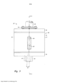
[018] A Figura 3 é uma vista frontal da junta de tubo flexível introduzida na Figura;[018] Figure 3 is a front view of the flexible tube joint introduced in the Figure;
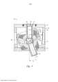
[019] A Figura 4 é um corte transversal lateral da junta de tubo flexível ao longo da linha 4-4 da Figura 3;[019] Figure 4 is a side cross-section of the flexible pipe joint along line 4-4 of Figure 3;
[020] A Figura 5 mostra os elementos flexíveis da Figura 4 reagindo a uma deflexão angular do tubo de extensão de cerca de 20 graus;[020] Figure 5 shows the flexible elements of Figure 4 reacting to an angular deflection of the extension tube of about 20 degrees;
[021] A Figura 6 mostra um conjunto de elementos flexíveis secundários da Figura 4 separado dos outros componentes da junta de tubo flexível;[021] Figure 6 shows a set of secondary flexible elements of Figure 4 separated from the other components of the flexible pipe joint;
[022] A Figura 7 mostra o conjunto de elementos flexíveis secundários da Figura 6 em um molde durante a moldagem dos elementos flexíveis secundários;[022] Figure 7 shows the set of secondary flexible elements of Figure 6 in a mold during the molding of the secondary flexible elements;
[023] A Figura 8 mostra uma construção alternativa da junta de tubo flexível da Figura 4 para facilitar a desmontagem e a substituição do conjunto de elementos flexíveis secundários;[023] Figure 8 shows an alternative construction of the flexible pipe joint of Figure 4 to facilitate disassembly and replacement of the secondary flexible element set;
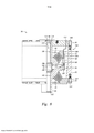
[024] A Figura 9 mostra uma construção alternativa para uma junta de tubo flexível na qual dois elementos flexíveis primários que funcionam em paralelo são localizados no mesmo lado de um centro de rotação comum em vez de em lados opostos;[024] Figure 9 shows an alternative construction for a flexible pipe joint in which two primary flexible elements operating in parallel are located on the same side of a common center of rotation rather than on opposite sides;
[025] A Figura 10 mostra um conjunto de elementos flexíveis secundários que inclui uma blindagem térmica;[025] Figure 10 shows a set of secondary flexible elements that includes a thermal shield;
[026] A Figura 11 mostra um corte transversal lateral de uma junta de tubo flexível que inclui um conjunto de elementos flexíveis secundários que tem uma blindagemtérmica;[026] Figure 11 shows a side cross-section of a flexible pipe joint that includes a set of secondary flexible elements that have a thermal shield;
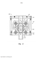
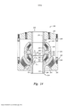
[027] A Figura 12 mostra uma vista frontal de outra junta de tubo flexível que inclui vários elementos flexíveis;[027] Figure 12 shows a front view of another flexible tube joint that includes several flexible elements;
[028] A Figura 13 mostra uma vista de topo da junta de tubo flexível da Figura 12;[028] Figure 13 shows a top view of the flexible tube joint of Figure 12;
[029] A Figura 14 é um corte transversal lateral ao longo da linha 14-14 da Figura 12;[029] Figure 14 is a side cross-section taken along line 14-14 of Figure 12;
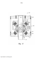
[030] A Figura 15 mostra um corte transversal lateral de uma construção alternativa para uma junta de tubo flexível que inclui vários elementos flexíveis primários e secundários; e[030] Figure 15 shows a side cross-section of an alternative construction for a flexible pipe joint that includes several primary and secondary flexible elements; and
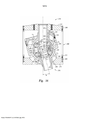
[031] A Figura 16 mostra os elementos flexíveis da Figura 15 reagindo a uma deflexão angular do tubo de extensão de cerca de 20 graus.[031] Figure 16 shows the flexible elements of Figure 15 reacting to an angular deflection of the extension tube of about 20 degrees.
[032] Embora a invenção seja suscetível a diversas modificações e formas alternativas, modalidades específicas dela foram mostradas nos desenhos e serão descritas em detalhe. Deve ficar entendido, contudo, que não se pretende limitar a invenção às formas específicas mostradas, mas, pelo contrário, a intenção é a de cobrir todas as modificações, equivalentes e alternativas que se incluam dentro do alcance da invenção definido pelas reivindicações anexas.[032] Although the invention is susceptible to several modifications and alternative forms, specific embodiments of it have been shown in the drawings and will be described in detail. It should be understood, however, that it is not intended to limit the invention to the specific forms shown, but rather is intended to cover all modifications, equivalents and alternatives that fall within the scope of the invention defined by the appended claims.
[033] Com referência à Figura 1, é mostrada uma embarcação de perfuração e produção offshore, designada genericamente por 10, que flutua sobre a superfície 11 da água. A embarcação flutuante é em particular uma plataforma com pernas de tensão (TLP) presa ao leito marinho 12 por meio de tendões 13, 14 e gabaritos de alicerce 15, 16. Embora não visível na Figura 1, há um conjunto de tendões que pendem de cada um dos quatro cantos da plataforma TLP 10 para um respectivo gabarito de quatro gabaritos de alicerce 15, 16. Além disto, cada um dos quatro cantos inferiores da plataforma TLP 10 é preso a uma respectiva linha de atracação 17, 18 usada para mover a plataforma em sentido lateral e para resistir a cargas de tempestade laterais.[033] Referring to Figure 1, an offshore drilling and production vessel, generically designated by 10, which floats on the
[034] Para transportar fluidos de perfuração e uma coluna de perfuração da TLP até um furo de poço 19 no leito marinho 12, e para remover hidrocarbonetos do poço quando a perfuração tiver sido concluída, um tubo ascendente de produção, designado genericamente por 20, estende-se a partir do furo de poço 19 até a TLP 10. O tubo ascendente 20 consiste em várias seções de tubo rígidas 21 unidas por juntas de tubo flexíveis 22. Uma junta de tubo flexível adequada é descrita, por exemplo, na patente norte-americana 5 133 578, de Whightsil, Sr. et alii, emitida em 28 de julho de 1992.[034] To transport drilling fluids and a TLP drill string to a
[035] É também mostrado na Figura 1 um tubo ascendente de exportação designado genericamente por 24, que pende de uma perna da TLP 10 em uma configuração catenária e toca no leito marinho 12. O tubo ascendente de exportação 24, por exemplo, é uma tubulação da TLP 10 até uma instalação onshore (não mostrada), ou até um sistema de bóia para carregar embarcações de armazenamento e descarregamento de produção flutuantes (EPSOs). O tubo ascendente de exporta ção 24 é semelhante ao tubo ascendente de produção 20 no sentido de que é constituído por várias seções de tubo rígidas 25 unidas por juntas de tubo flexíveis elas- toméricas 26. Uma junta de tubo flexível 27 no topo do tubo ascendente 24 é montada em um receptáculo com fendas e entrada lateral 34 preso a uma perna da TLP 10.[035] Also shown in Figure 1 is an export riser generally designated 24, which hangs from one leg of the
[036] A Figura 2 mostra o receptáculo com fendas e entrada lateral 34. O receptáculo 34 é uma soldagem que consiste em um anel de carga usinado, forjado, 41 e várias chapas 42, 43. As chapas 42, 43, que funcionam como membranas e flanges, servem para estabilizar o anel de carga 41 assim como cargas de suporte entre a perna da TLP e o tubo ascendente de exportação.[036] Figure 2 shows the receptacle with slots and
[037] Durante a instalação, a parte posterior do receptáculo 34 é soldada ou presa de outro modo à perna da TLP, e a junta de tubo flexível superior do tubo ascendente de exportação é inserida no anel de carga 41. O receptáculo inclui uma fenda anterior genericamente designada por 44 para facilitar a entrada lateral do tubo ascendente de exportação durante a instalação.[037] During installation, the rear portion of the
[038] Juntas flexíveis para tubos ascendentes e para montar tendões em uma TLP foram fabricadas e estocadas em diversos tamanhos para lidar com diversos tamanhos padrão de tubos ascendentes ou tendões. Entretanto, podem surgir situações em que seria desejável aumentar a capacidade de sustentação de carga ou tempo de vida útil de uma junta flexível para um dado tamanho de alojamento ou pegada. Isto é especialmente verdadeiro para a junta de tubo flexível superior de um tubo ascendente, isto porque esta junta flexível é tipicamente montada em uma embarcação flutuante que tem um receptáculo de montagem casado com uma pegada de alojamento específica.[038] Flexible riser joints and for mounting tendons on a TLP have been manufactured and stocked in various sizes to handle various standard sizes of risers or tendons. However, situations may arise where it would be desirable to increase the load-bearing capacity or service life of a flexible joint for a given housing size or footprint. This is especially true for the upper flexible pipe joint of a riser, because this flexible joint is typically mounted on a floating vessel that has a mounting receptacle matched to a specific housing footprint.
[039] Por exemplo, inicialmente um receptáculo de montagem é selecionado e dimensionado para condições de serviço antecipadas, e em seguida um receptáculo de montagem é soldado na embarcação flutuante. Se as condições de serviço se alterassem, então poderia ser difícil substituir o receptáculo de montagem e caro de instalar um novo receptáculo de montagem. É necessário aumentar as condições de carga uma vez que um poço novo ou mais profundo foi perfurado em um local existente, de modo que o fluido de produção de temperatura mais elevada venha a ser extraído no local existente, ou pode ser necessário aumentar as condições de carga uma vez que a produção em um local existente foi concluída e a embarcação flutuante foi movida até um novo local onde o leito marinho é mais profundo, de modo que a junta de tubo flexível deve lidar com uma tensão mais elevada. Seja como for, seria desejável instalar uma junta de tubo flexível nova, de capacidade mais elevada no receptáculo de montagem existente.[039] For example, initially a mounting receptacle is selected and sized for anticipated service conditions, and then a mounting receptacle is welded to the floating vessel. If service conditions change, then it could be difficult to replace the mounting receptacle and expensive to install a new mounting receptacle. It is necessary to increase loading conditions once a new or deeper well has been drilled in an existing location, so that the higher temperature production fluid will be extracted from the existing location, or it may be necessary to increase the loading conditions. loading once production at an existing site has been completed and the floating vessel has been moved to a new location where the seabed is deeper, so the hose joint must handle a higher stress. In any case, it would be desirable to install a new, higher capacity flexible pipe joint in the existing mounting receptacle.
[040] A Figura 3 mostra a junta de tubo flexível 27 mais detalhadamente. Nesta modalidade específica, a junta de tubo flexível 27 tem um alojamento externo 50 e um tubo de extensão 54 que se estende a partir do alojamento externo 50. O alojamento externo inclui um anel de sustentação inferior 51, um corpo cilíndrico 52 e um flange de fixação 53. Por exemplo, estes componentes são feitos de uma liga de aço resistente à corrosão. O corpo cilíndrico 53 tem uma série de orifícios de resfriamento 57, 58, 59 afastados entre si em volta da sua circunferência para permitir a circulação de água do mar para remoção do calor da junta de tubo flexível quando o fluido de alta temperatura é transportado através da junta de tubo flexível.[040] Figure 3 shows the flexible pipe joint 27 in more detail. In this specific embodiment, the flexible tube joint 27 has an
[041] Quando em uso, a junta de tubo flexível 27 é assentada em um receptáculo cativo (34 na Figura 2) que pode sustentar com segurança o peso e a carga da junta de tubo flexível 27. O flange de fixação 53 é aparafusado a um flange (56 na Figura 3) de um segmento de tubo (28 na Figura 3) para transportar fluido através da junta de tubo flexível entre o segmento de tubo 28 e o tubo de extensão 54. Quando sustenta uma carga de tração sobre o tubo de extensão 54 com relação ao alojamento externo 50, a junta de tubo flexível 27 permite uma faixa de deslocamento angular (θ) do tubo de extensão 54 com relação ao alojamento externo 50. Conforme mostrado na Figura 3, um deslocamento angular (θ) do tubo de extensão 54 ocorre quando o tubo de extensão gira em volta de um centro de rotação 63 a partir de uma orientação vertical, mostrada em linhas cheias, até uma orientação inclinada 55, mostrada em linhas tracejadas.[041] When in use, the flexible tube joint 27 is seated in a captive receptacle (34 in Figure 2) that can safely support the weight and load of the flexible tube joint 27. The
[042] Para aumentar a capacidade de sustentação de carga ou tempo de vida útil de uma junta flexível para um dado tamanho ou pegada de alojamento, um ou mais elementos flexíveis primários e um ou mais elementos flexíveis secundários são incluídos em um alojamento comum. Os elementos flexíveis primários lidam com cargas axiais sobre a junta de tubo, e os elementos flexíveis elastoméricos secundárioscontém pressão de fluido dentro da junta de tubo flexível. Em particular, os elementosflexíveis elastoméricos primários asseguram que cargas axiais típicas sobre a junta de tubo não causem deslocamento axial excessivo para os elementos flexíveiselastoméricos secundários, e os elementos flexíveis secundários reduzem ou eliminam a pressão do fluido sobre o elemento flexível primário. Além disto, os ele-mentosflexíveis secundários podem ter um tamanho compacto de modo que não seja necessário aumentar o tamanho total da junta de tubo flexível para acomodar os elementos flexíveis elastoméricos secundários.[042] To increase the load-bearing capacity or service life of a flexible joint for a given housing size or footprint, one or more primary flexible elements and one or more secondary flexible elements are included in a common housing. The primary flexible elements handle axial loads on the pipe joint, and the secondary elastomeric flexible elements contain fluid pressure within the flexible pipe joint. In particular, the primary elastomeric flexible elements ensure that typical axial loads on the pipe joint do not cause excessive axial displacement for the secondary elastomeric flexible elements, and the secondary flexible elements reduce or eliminate fluid pressure on the primary flexible element. In addition, the secondary flexible elements can be compact in size so that it is not necessary to increase the overall size of the flexible tube joint to accommodate the secondary elastomeric flexible elements.
[043] A Figura 4 mostra uma configuração preferida que inclui um elemento flexível primário inferior 61 e um elemento flexível primário superior 62. Os elementosflexíveis primários 61 e 62 são empilhados de maneira coaxial em volta de um centro de rotação comum 63 e acoplados ao tubo de extensão 54 e ao anel de sustentação inferior 51 de modo a reagirem em paralelo à rotação do tubo de extensão 54 em volta do centro de rotação comum e ao deslocamento axial do tubo de extensão 54. Nesta modalidade específica, a junta de tubo flexível 27 tem um alojamento interno 65 soldado em um flange superior 66 do tubo de extensão 54, e um tubo interno 64 soldado no flange de fixação 53. Por exemplo, o alojamento interno 65 e o tubo interno 64 são feitos de uma liga de aço resistente à corrosão. O elemento flexível primário inferior 61 é disposto entre os e ligado ao anel de sustentação inferior 51 e ao flange superior 66 do tubo de extensão 54. O elemento flexível primário superior 62 é disposto entre os e ligado a um flange inferior 67 do tubo interno 64 e ao alojamento interno 65.[043] Figure 4 shows a preferred configuration that includes a lower primary
[044] Em geral, uma vez que o tubo de extensão 54 e o alojamento interno 65 são unidos entre si, o elemento flexível primário superior 62 e o elemento flexível primário inferior 61 são forçados a reagir em paralelo e, assim, a deslocar-se e girar no mesmo grau. Portanto, a carga total devida à tensão e rotação do tubo ascendenteé distribuída entre o elemento flexível superior 62 e o elemento flexível inferior 61 em proporção à sua relativa rigidez. O elemento flexível inferior 61 transfere sua carga sua carga diretamente para dentro do anel de sustentação inferior 51, enquanto o elemento flexível superior 62 transfere sua carga para dentro do tubo interno 64. O tubo interno 64 em seguida transfere essa carga para dentro do flange de fixação 53 através de uma conexão soldada. O flange de fixação 53 transfere essa carga através de outra conexão para baixo até o anel de sustentação inferior 51.[044] In general, since the
[045] A junta de tubo flexível 27 inclui também um revestimento interno superior 71, um revestimento interno inferior 72 e um anel centralizador 73. Um elementoflexível elastomérico anular secundário superior 74 é disposto entre o anel centralizador 73 e o revestimento interno superior 71, e um elemento flexível elasto- mérico anular secundário inferior 75 é disposto entre o anel centralizador 73 e o re-vestimento interno inferior 72. O conjunto do revestimento interno superior 71, do revestimento interno inferior 72, do anel centralizador 73, do elemento flexível elas- tomérico anular secundário superior 74 e do elemento flexível elastomérico anular secundário inferior 75 é moldado como um todo como uma unidade única, genericamente designada por 70, conforme também descrito a seguir com referência às Figuras 6 e 7.[045] The flexible tube joint 27 also includes an upper
[046] Todos os elementos flexíveis 61, 62, 74, 75 da junta de tubo flexível 27 compartilham o mesmo centro de rotação 63 para permitir uma faixa de deslocamento angular desatado do tubo de extensão 54 durante a operação. O anel centralizador 73 é um anel esférico que tem um ponto central que coincide com este centro de rotação comum 63. O anel centralizador 73 tem também um entalhe 76 em volta do seu equador.[046] All
[047] Os elementos flexíveis secundários 74, 75, o anel centralizador 73, o revestimento interno superior 71 e o revestimento interno inferior 72 isolam a cavidade interna 68 do fluido de produção. Isto, por sua vez, elimina a cabeça de pres- são resultante que de outro modo seria introduzida se se deixasse a pressão do fluido de produção entrar na cavidade interna 68 e chegasse aos elementos flexíveis primários 61 e 62. Assim, o conjunto dos revestimentos internos 71, 72 e do anel centralizador 73 e dos elementos flexíveis secundários 74, 75 funciona como uma unidade de isolamento de pressão 70, que cria uma redundância nas vedações entre o fluido de produção e as condições ambientais fora da junta de tubo flexível 27. O alojamento interno 65, por exemplo, tem um orifício de pressão 78 para medir ou ajustar a pressão na cavidade interna. O orifício de pressão 78, por exemplo, inclui um furo através do alojamento interno 65, e este furo é tampado com uma bucha, válvula ou calibrador de pressão acessível externamente através do orifício de resfriamento 57.[047] The secondary
[048] Em uso, quando da transferência do fluido de produção da embarcação flutuante para o tubo ascendente de exportação (24 na Figura 1), o fluido de produção escoa para baixo através de uma abertura 69 no flange de fixação 53 para dentro do tubo interno 64. Em seguida, o fluido de produção escoa do tubo interno 64 para baixo através do revestimento interno superior 71, através do anel centralizador 73, através do revestimento interno inferior 72 e através do tubo de extensão 54.[048] In use, when transferring the production fluid from the floating vessel to the export riser (24 in Figure 1), the production fluid flows down through an
[049] É também possível utilizar uma junta de tubo flexível mostrada na Figura no tubo ascendente de produção (20 na Figura 1). Neste caso, o fluido de produção do furo de poço escoaria para cima através do te 54 e em seguida para cima através do revestimento interno inferior 72, do anel centralizador 73, do revestimento interno superior 71, do tubo interno 54 e em seguida para cima através da abertura 69 do flange de fixação 53.[049] It is also possible to use a flexible pipe joint shown in the Figure on the production riser (20 in Figure 1). In this case, the production fluid from the wellbore would flow upwards through the
[050] A construção da junta de tubo flexível 27 requer dois conjuntos de junta flexível primários a serem moldados separadamente. Em um processo de moldagem, o elastômero do elemento flexível inferior 61 é ligado ao anel de sustentação inferior 51 e ao tubo de extensão 54 utilizando-se um anel de duas peças dividido (não mostrado). Quando o processo de moldagem é completado, as duas peças do anel dividido são desmontadas uma da outra de modo a se remover o anel dividido do conjunto moldado. Outros detalhes referentes a um molde com tal anel dividido são encontrados na Figura 5 e da coluna 5, linha 47, até a coluna 6, linha 2, da patente norte-americana 4 708 758, de McGregor, emitida em 24 de novembro de 1987.[050] The construction of flexible pipe joint 27 requires two primary flexible joint assemblies to be molded separately. In a molding process, the lower
[051] De maneira semelhante, quando o elemento flexível superior 62 é moldado, o elastômero do elemento flexível superior é ligado ao flange inferior 67 do tubo interno 64 e ao alojamento interno 65. Neste caso, há necessidade de um anel dividido porque a conformação do tubo interno 64 e do alojamento interno 65 permite a utilização de um anel cônico maciço no processo de moldagem.[051] Similarly, when the upper
[052] A junta de tubo flexível mostrada na Figura 4 é fabricada a partir da montagem do elemento flexível inferior 61 e da montagem do elemento flexível superior 62 pela inserção do revestimento interno inferior 72 do conjunto de revestimento interno no tubo de extensão 54. Em seguida, o conjunto de elemento flexível primário superior 62 é abaixado até a posição com o tubo interno 64 encaixado sobre o revestimento interno superior 71 do conjunto de revestimento interno de modo que o revestimento interno 71 seja inserido no tubo interno 64 até que o alojamento interno 65 venha a ser assentada sobre o flange superior 66 do tubo de extensão 54. Em seguida, o alojamento interno 65 é soldada no flange superior 66 do tubo de extensão 54. Em seguida, a extremidade inferior do revestimento interno inferior 72 é soldada na extremidade inferior do tubo de extensão 54, e a extremidade superior do revestimento interno superior 71 é soldada na extremidade superior do tubo interno 64. Em seguida, o flange de fixação 53 é encaixado sobre o tubo interno 64 e colocado sobre o corpo cilíndrico 52, e a extremidade superior do tubo interno é soldada no flange de fixação. Em seguida, o flange de fixação 53 é soldado no corpo cilíndrico 52.[052] The flexible tube joint shown in Figure 4 is fabricated from the assembly of the lower
[053] A Figura 5 mostra a junta de tubo flexível 27 quando o tubo de extensão 54 tiver sido submetido a um deslocamento angular máximo (θ). O anel centralizador 73 também gira em volta do centro de rotação 63, mas seu deslocamento an- gular (9) é de cerca da metade do deslocamento angular (θ) do tubo de extensão 54. Portanto, pela junção mecânica do elemento flexível secundário superior 74 e do elemento flexível secundário inferior 75 em série entre o alojamento 50 e o tubo de extensão 54, o deslocamento angular de cada um dos elementos flexíveis secundários causado pelo deslocamento anular (θ) do tubo de extensão é de cerca da metade do deslocamento angular (θ) do tubo de extensão.[053] Figure 5 shows the flexible tube joint 27 when the
[054] Em geral, a deformação angular de um elemento flexível é diretamente proporcional ao deslocamento angular θ do tubo de extensão e diretamente proporcional à razão do deslocamento radial do elemento flexível do centro de rotação 63 dividido pela espessura radial do elemento flexível. Conforme mostrado na Figura 5, por exemplo, cada um dos elementos flexíveis secundários 74, 75 é deslocado por um raio interno comum R1 do centro de rotação comum 63, e cada um dos elementos flexíveis primários 61, 62 é deslocado por um raio externo comum R2 do centro de rotação comum 63. Uma vez que o raio externo R2 é muito maior que o raio interno R1 e uma vez que os elementos secundários 74, 75 são mecanicamente li-gados em série e os elementos flexíveis primários 61, 62 são mecanicamente ligados em paralelo entre o alojamento e o tubo de extensão, cada um dos elementos flexíveis secundários pode ter uma espessura radial que é muito menor que a espessura radial de cada um dos elementos flexíveis primários, de modo que a unidade de isolamento de pressão 70 possa ter um tamanho compacto.[054] In general, the angular deformation of a flexible element is directly proportional to the angular displacement θ of the extension tube and directly proportional to the ratio of the radial displacement of the flexible element from the center of
[055] É também possível que cada um dos elementos flexíveis secundários 74, 75 sejam constituídos de um elastômero que tem um módulo mais baixo que o do elastômero de cada um dos elementos flexíveis primários 61, 62 uma vez que os elementos flexíveis secundários 61, 62 são projetados basicamente para conter a pressão, e os elementos flexíveis primários 61, 62 são projetados basicamente para resistir à deformação angular e axial. Com a utilização de uma composição elasto- mérica de módulo mais baixo nos elementos flexíveis secundários 74, 75 que a existente nos elementos flexíveis primários 61, 62, os elementos flexíveis secundários podem tolerar uma deformação angular maior que a dos elementos flexíveis primá- rios e, portanto, a espessura radial dos elementos flexíveis primários pode ser reduzida ainda mais com relação à espessura radial dos elementos flexíveis primários. Entretanto, conforme também descrito a seguir com referência às Figuras 14 e 15, é também possível construir juntas de tubo flexíveis nas quais os elementos flexíveis primários e secundários têm conformações semelhantes e a mesma composição elastomérica e nas quais os elementos flexíveis secundários podem ser submetidos a uma pressão e a uma temperatura mais elevadas que aquelas às quais são submetidos os elementos flexíveis primários.[055] It is also possible that each of the secondary
[056] A Figura 6 mostra a unidade de isolamento de pressão 70 separada de qualquer junta de tubo flexível específica na qual ela pode ser utilizada. Em geral, cada um dos revestimentos interno superior 71 e revestimento interno inferior 72 têm uma parte cilíndrica afastada do anel centralizador 73 e uma conformação hemisféricapróxima do anel centralizador. A parte cilíndrica de cada um dos revestimentos interno superior 71 e revestimento interno inferior 72 têm um comprimento que depende da configuração de junta de tubo flexível específica. Em geral, o comprimento da parte cilíndrica de um revestimento interno é selecionado para soldagem adequada da extremidade do revestimento interno em outro componente de metal da junta de tubo flexível, tal como o tubo de extensão ou um tubo interno.[056] Figure 6 shows the
[057] A Figura 7 mostra um molde de compressão para moldar a unidade de isolamento de pressão 70 da Figura 6. Na Figura 7, o molde de compressão tem componentes tanto internos quanto externos. Os componentes internos são um mandril de diâmetro interno ou uma câmara inflável 160 e um par de anéis de encaixeelastoméricos retráteis ou removíveis 161, 162. Os anéis de encaixe 161, 162 são pré-moldados do elastômero e são curados e em seguida revestidos com um agente liberador de molde. Os anéis de encaixe 161, 162 são dimensionados de modo a atuarem como uma represa ou tampão para a borracha não curada que se torna o elemento flexível secundário superior 74 e o elemento flexível secundário inferior 75. Os componentes externos incluem um anel de molde externo 163 que é inserido no entalhe equatorial 76 do anel centralizador 73 para manter os componentes 71, 72, 73, 74, 75 da unidade de isolamento de pressão a uma altura pré-fixada. Os componentes externos incluem também uma série de anéis de fixação 164, 165, 166, 167, 168, 169. Os anéis de fixação externos 166, 167 têm invólucros de vapor 171, 172 para aquecer o molde de modo a curar a borracha do elemento flexível secundário superior 74 e do elemento flexível secundário inferior 75.[057] Figure 7 shows a compression mold for molding the
[058] A Figura 8 mostra uma construção alternativa para uma junta de tubo flexível 90 para facilitar a desmontagem. A junta de tubo flexível 90 inclui um alojamento externo 100 e um tubo de extensão 84 que se estende a partir do alojamento externo. O alojamento externo 100 é constituído de um anel de sustentação inferior 81, um corpo cilíndrico 82 e um flange de fixação 83, a junta de tubo flexível 90 inclui também um tubo de extensão 84, um elemento flexível elastomérico primário inferior 91, um elemento flexível elastomérico primário superior 92, um tubo interno 94, um alojamento interno 95, um revestimento interno superior 101, um revestimento interno inferior 102, um anel centralizador 103, um elemento flexível elastomérico secundário superior 104 e um elemento flexível secundário inferior 105. Os elementos flexíveis elastoméricos 91, 92, 104, 105 têm um centro de rotação comum 93. O anel centralizador 103 é um anel esférico que tem um ponto central que coincide com este centro de rotação comum 93.[058] Figure 8 shows an alternative construction for a hose joint 90 to facilitate disassembly. Flexible tube joint 90 includes an
[059] Durante a construção da junta de tubo flexível 90, quando o elemento flexível primário inferior 91 é moldado, o elastômero do elemento flexível primário inferior 91 torna-se ligado ao anel de sustentação inferior 981 e ligado ao tubo de extensão 84. Quando o elemento flexível primário superior 92 é moldado, o elastô- mero do elemento flexível primário superior 92 torna-se ligado ao alojamento interno 95 e ligado ao tubo interno 94. O elemento flexível secundário superior 104 e o elementoflexível secundário inferior 105 são moldados ao mesmo tempo, formando uma unidade de isolamento de pressão única 110 que consiste no revestimento interno superior 101, no revestimento interno inferior 102 e no anel centralizador 103.[059] During the construction of the flexible tube joint 90, when the lower primary
[060] A unidade de isolamento de pressão 110, que contém os elementos flexíveis secundários 104, 105, é em seguida colocada sobre a montagem do ele- mento flexível inferior 91, e o revestimento interno inferior 102 é inserido no tubo de extensão 84. Em seguida, a montagem do elemento flexível superior 92 é colocada sobre a montagem do elemento flexível inferior 91, e o flange superior 96 do tubo de extensão 84 é preso ao alojamento interno 95 por uma série de cavilhas 105. Uma gaxeta de metal anular de extremidade 106 veda a junta entre o flange superior 96 do tubo de extensão 84 e o alojamento interno 95. Em seguida, o corpo cilíndrico 82 é colocado sobre o anel de sustentação inferior 81 e preso ao anel de sustentação inferior 81 por uma série de cavilhas 107. Em seguida, a extremidade inferior do revestimento interno inferior 102 é soldada na extremidade inferior do tubo de extensão 84, e a extremidade superior do revestimento interno superior 101 é soldada na extremidade superior do tubo interno 94. Em seguida, uma linha de pressão flexível 109 é ligada entre um orifício de pressão 108 no alojamento interno 95 e um orifício de pressão 114 no flange de fixação 83, de modo que o orifício de pressão 114 no flange de fixação 83 permita a medição ou ajuste da pressão do fluido dentro de uma cavidade interna 98. Em seguida, o flange de fixação 83 é encaixado no tubo interno 94, e o tubo interno 94 é soldado no flange de fixação 83. Em seguida, o flange de fixação 83 é preso ao corpo cilíndrico 82 por uma série de cavilhas 106.[060] The
[061] Durante o uso em um ambiente offshore, o orifício de pressão 114 permite a detecção externa de qualquer falha dos elementos flexíveis secundários 104, 105 para conter o fluido de produção pressurizado. Se uma falha for detectada, então a substituição da unidade de isolamento de pressão 110, que inclui os elementosflexíveis secundários 104, 105, pode ser efetuada imediatamente no campo, ou pode-se programar a realização da substituição para um momento futuro se for mais conveniente retardar a substituição. Até a substituição da unidade de isolamento de pressão, o elemento flexível primário superior 92 conterá o fluido de produção dentro da cavidade interna 98. A câmara externa 99 pode ser enchida com um fluido incompressível, tal como glicol de propileno ou glicol de poli-alquileno, de modo que a carga de pressão do fluido de produção na cavidade interna 98 seja compartilhada entre o elemento flexível primário superior 92 e o elemento flexível primário inferior 91.[061] During use in an offshore environment,
[062] Para desmontagem, as cavilhas 106 são removidas de modo que o flange de fixação 83 não fique mais preso ao corpo cilíndrico 82. Em seguida, a solda 113 entre o tubo interno 94 e o flange de fixação 83 é eliminada por esmerilha- mento de modo que o flange de fixação possa ser removido do tubo interno. Também a solda 111 entre o revestimento interno superior 101 e o tubo interno 94 é eli-minada por esmerilhamento, e a solda 112 entre o revestimento interno inferior e o tubo de extensão 84 é eliminada por esmerilhamento. Em seguida, as cavilhas 107 são removidas de modo que o conjunto do elemento flexível superior 107 possa ser removido do conjunto do elemento flexível inferior 103. Em seguida, a unidade de isolamento de pressão 110 (inclusive o revestimento interno superior 101, o revestimento interno inferior 102, o anel centralizador 103, o elemento flexível secundário superior 104 e o elemento flexível secundário inferior 105) é removida do tubo de extensão 84. Esta unidade de isolamento de pressão 110 pode ser substituída por uma nova unidade de isolamento de pressão, e a junta de tubo flexível 90 pode ser então remontada no campo.[062] For disassembly, the
[063] A junta de tubo flexível 27 da Figura 4 e a junta de tubo flexível 90 da Figura 8 devem ser utilizadas em uma aplicação, tal como um tubo ascendente ca- tenário, na qual o tubo de extensão 54 ou 84 é submetido a uma tensão axial em vez de uma compressão axial com relação ao alojamento externo da junta de tubo. Caso contrário, esta compressão se traduziria em tensão sobre os elementos flexíveis, e a compressão axial sobre o tubo de extensão 54 ou 84 limitaria a vida útil de serviço da junta de tubo flexível. Para aplicações em que o tubo de extensão pode ser submetido uma compressão axial substancial, a junta de tubo flexível deve ser construída, conforme descrito a seguir, para limitar a transmissão da compressão axial para os elementos flexíveis secundários.[063] The flexible tube joint 27 of Figure 4 and the flexible tube joint 90 of Figure 8 should be used in an application, such as a catenary riser, in which the
[064] A Figura 9 mostra uma junta de tubo flexível 120, que tem um alojamento externo 130 e um tubo de extensão 122 que se estende a partir do alojamento externo. O alojamento externo 130 é constituída de um corpo cilíndrico 121 e um flange de fixação 123. O flange de fixação 123 é soldado no corpo cilíndrico 121. Um elemento flexível elastomérico anular primário inferior 131 é ligado ao corpo cilíndrico 121 e ligado a um invólucro de extensão 132 do tubo de extensão 122. Um elementoflexível elastomérico anular primário superior 133 é ligado a um alojamento interno 134 e ligado a um flange superior 135 de um revestimento interno 147 do tubo de extensão 122. O alojamento interno 134 é soldada no flange de fixação 123 e a extremidade inferior do invólucro 132 do tubo de extensão é soldada no revestimento interno 147 do tubo de extensão.[064] Figure 9 shows a flexible tube joint 120, which has an
[065] A junta de tubo flexível 120 inclui uma unidade de isolamento de pressão 140. A unidade de isolamento de pressão inclui um revestimento interno superior 141, um revestimento interno inferior 142, um anel centralizador esférico 143, um elemento flexível elastomérico anular secundário superior 144 ligado entre o revestimento interno superior 141 e o anel centralizador 143, e um elemento flexível elastomérico anular inferior 145 ligado entre o revestimento interno 142 e o anel centralizador 143. O revestimento interno superior 141 é disposto em uma abertura 137 no flange de fixação 123, e o revestimento interno inferior 142 é disposto no revestimento interno 147 do tubo de extensão.[065] The flexible pipe joint 120 includes a
[066] Os elementos flexíveis primários 131, 133 e os elementos flexíveis secundários 144, 145 têm um centro de rotação comum 136. Os elementos flexíveis secundários 144, 145 são empilhados de maneira coaxial em lados opostos do centro de rotação comum 136 a um raio interno comum R1 do centro de rotação comum. Os elementos flexíveis primários 131, 133 são empilhados e aninhados de maneira coaxial no mesmo lado do centro de rotação comum. O elemento flexível primário superior 133 é disposto a um raio externo R2 do centro de rotação comum 136, de modo que R2 seja maior que o raio interno R1. O elemento flexível primário inferior 131 é disposto a um raio externo R3 do centro de rotação comum 136, de modo que R2 seja maior que o raio interno R1. Os elementos flexíveis secundários 144, 145 são mecanicamente unidos em série com o anel centralizador 143 entre o alojamento externo 130 e o tubo de extensão 122, os elementos flexíveis primários 131, 133 são mecanicamente unidos em paralelo uns com os outros, e cada um dos elementos flexíveis primários 131, 133 é mecanicamente unido ao alojamento externo 130 e ao tubo de extensão 122 em paralelo com a combinação em série dos elementos flexí-veissecundários 144, 145.[066] The primary
[067] O invólucro de extensão 132 tem um flange hemisférico 138 que encosta em uma superfície hemisférica externa complementar 139 do alojamento interno 134. A compressão axial do tubo de extensão 122 com relação ao alojamento externo 130 faz com que o flange hemisférico 138 do invólucro 132 do tubo de extensão entre em contato com a superfície hemisférica externa 139 do alojamento interno 134, de modo que a força de compressão axial do tubo de extensão 122 seja transferida para o alojamento externo 130 através do invólucro de extensão 132, do alojamento interno 134 e do flange de fixação 123. Portanto, a força de compressão axial não é aplicada à unidade de isolamento de pressão 140 e seus elementos flexíveis secundários 144, 145.[067] The
[068] A Figura 10 mostra uma unidade de isolamento de pressão 150 que inclui um revestimento interno superior 182, um revestimento interno inferior 182, um anel centralizador 183, um elemento flexível elastomérico anular secundário superior 184 e um elemento flexível elastomérico anular inferior 185. São dispostos no anel centralizador 183 um revestimento interno de blindagem térmica superior 186 e um revestimento interno de blindagem térmica inferior 187. Os revestimentos internos de blindagem térmica 186, 187 são feitos de material de baixa condutividade térmica, tal como uma liga de níquel-cromo-ferro que contém um mínimo de 72% de níquel e cobalto, 14-17% de cromo e 6-10% de ferro, tal como 76% de níquel, 17% de cromo e 7% de ferro. O termoplástico preferido é a poli-éter-éter-cetona, ou PEEK, descrita na patente norte-americana 7 341 283, de Moses et al, emitida em 11 de março de 2008.[068] Figure 10 shows a pressure isolation unit 150 that includes an upper
[069] Os revestimentos de blindagem térmica 186, 187 são montados em uma junta de esfera e soquete. O revestimento interno e blindagem térmica inferior 187 é formado com um flange esférico superior 188, e o revestimento interno de blindagem térmica superior 186 é formado com um flange hemisférico inferior 189. O flange esférico superior 188 é inserido no flange hemisférico inferior 189, e em seguida a extremidade inferior do flange hemisférico inferior 189 é plissada em volta do flange esférico superior 189. O flange esférico superior 188 é dotado de fendas para portar um anel de vedação de metal resiliente dividido 190, que se expande de encontroà periferia interna do flange hemisférico inferior 189 de modo a conter o fluido de produção dentro do tubo de extensão. Assim, o anel de vedação 190 funciona de maneira semelhante a um anel de pistão em um motor de combustão interna. O anel de vedação 190, contudo, não precisa proporcionar uma vedação contra a pressão, e em vez disso o anel de vedação 190 impede que o fluido de produção circule livrementeatravés de um encaixe com folga entre os revestimentos de blindagem térmica 186, 187.[069]
[070] Para montagem dos revestimentos internos de blindagem térmica 186, 187 na unidade de isolamento de pressão 180, o anel centralizador 183 é formado por dois anéis hemisféricos 192, 193 unidos por uma solda equatorial 194. Quando o elemento flexível secundário superior 184 é moldado, o elastômero do elemento flexível secundário superior 184 é ligado ao revestimento interno superior 181 e ligado ao anel hemisférico superior 192. Quando elemento flexível secundário inferior 185 é moldado, o elastômero do elemento flexível secundário inferior 185 é ligado ao revestimento interno inferior 182 e ligado ao anel hemisférico inferior 193. Em seguida, o conjunto do elemento flexível secundário superior 184 é encaixado sobre o revestimento interno de blindagem térmica superior 186 do conjunto de blindagemtérmica, e o conjunto do elemento flexível secundário inferior 185 é encaixado sobre o revestimento interno de blindagem térmica 187 do conjunto de blindagem térmica, de modo que os dois anéis hemisféricos 192, 193 sejam unidos em volta dos flanges 188, 189 do conjunto de blindagem térmica e soldados uns nos outros formando a solda equatorial 194.[070] For mounting the thermal shield
[071] A extremidade superior do revestimento interno de blindagem térmica 186 tem um encaixe de folga apertado dentro de um recesso cilíndrico no revesti- mento interno de blindagem térmica superior 181, e o revestimento interno de blindagemtérmica inferior 187 tem um encaixe de folga apertado dentro de um recesso cilíndrico no revestimento interno de isolamento de pressão inferior 182. Portanto, os revestimentos internos de blindagem térmica 186, 187 não apresentam praticamente resistência ao revestimento interno de isolamento de pressão inferior 182, que é afastado do revestimento interno de isolamento de pressão superior 181 quando é aplicada tensão ao tubo de extensão com relação ao alojamento de uma junta de tubo flexível que inclui a unidade de isolamento de pressão 180. Na ausência de força axial do tubo de extensão, há uma determinada folga axial (z) entre as extremidades dos revestimentos de blindagem térmica 186, 187 e os recessos cilíndricos nos revestimentos internos de isolamento de pressão 181, 182. Os revestimentos internos de blindagem térmica 186, 187 resistirão à força de compressão entre o revestimento interno de isolamento de pressão inferior 182 e o revestimento interno de isolamento de pressão superior 181 quando a compressão aplicada ao tubo de extensão com relação ao alojamento atinge um determinado limite no qual a folga axial “z” é reduzida a zero.[071] The upper end of the thermal shield
[072] A Figura 11 mostra a unidade de isolamento de pressão 180 da Figura 10 montada em uma junta de tubo flexível 200. A junta de tubo flexível 200 inclui um alojamento externo 210 constituída de um anel de sustentação inferior 201, um corpo cilíndrico 202 e um flange de fixação 203. Uma série de cavilhas 219 prendem o anel de sustentação inferior 201 ao corpo cilíndrico 202, e uma série de cavilhas 218 prendem o flange de fixação 203 ao corpo cilíndrico 202. Um tubo de extensão 204 estende-se a partir do alojamento externo 210. Um elemento flexível elastoméri- co anular primário inferior 211 é disposto no alojamento externo 210 para montar o tubo de extensão 204 no alojamento externo 210, e um elemento flexível elastoméri- co primário superior 212 é também disposto no alojamento para montar o tubo de extensão 204 no alojamento externo 210. Os elementos flexíveis primários compartilham um centro de rotação comum 213 e são empilhados de maneira coaxial.[072] Figure 11 shows the
[073] Durante a moldagem do elemento flexível primário inferior 211, o elas- tômero do elemento flexível primário inferior 211 é ligado ao anel de sustentação inferior 201 e ligado a um flange superior 216 do tubo de extensão 204. Durante a moldagem do elemento flexível primário superior 212, o elastômero do elemento flexível primário superior 212 é ligado ao alojamento interno 215 e ligado a um flange inferior 217 de um tubo interno 214. Após a montagem da unidade de isolamento de pressão 180, o revestimento interno de pressão inferior 182 da unidade de isolamen-to de pressão 180 é inserido em um recesso cilíndrico no tubo interno 214 quando o conjunto do elemento flexível primário superior 212 é encaixado sobre o conjunto do elemento flexível primário inferior 211. Desta maneira, a unidade de isolamento de pressão 180 torna-se assentada dentro de uma cavidade limitada por uma superfície hemisférica interna do flange superior 216 do tubo de extensão 204 e uma superfície hemisférica interna do flange inferior 217 do tubo interno 204. Em seguida, a extremidade inferior do alojamento interno 215 é soldada na extremidade superior do flange superior 216 do tubo de extensão 204. Em seguida, a extremidade superior do revestimento interno de pressão 181 da unidade de isolamento de pressão 180 é soldada no tubo interno 214, e a extremidade inferior do revestimento interno de pressão inferior 182 da unidade de isolamento de pressão 189 é soldada no tubo de extensão 204. Em seguida, o corpo cilíndrico 202 é aparafusado ao anel de sustentação inferior 201, e o flange de fixação 203 é encaixado sobre a extremidade superior do tubo interno 214 e aparafusado ao corpo cilíndrico 202. Em seguida, o tubo interno 214 é soldado no flange de fixação 203.[073] During the molding of the lower primary
[074] As Figuras 12, 13 e 14 mostram diversas vistas de uma junta de tubo flexível 230 na qual os elementos flexíveis secundários 254, 255 podem, mas não precisam, ter a mesma composição elastomérica do elemento flexível primário 241 e na qual os elementos flexíveis secundários são diretamente submetidos à pressão e à temperatura do fluido de transporte e funcionam como uma unidade de isolamento de pressão.[074] Figures 12, 13 and 14 show several views of a flexible tube joint 230 in which the secondary
[075] Conforme mostrado na Figura 12, a junta de tubo flexível 230 inclui um alojamento externo 240 constituído de um anel de sustentação 231, um corpo cilíndrico 232 e um flange de fixação 233. Um tubo de extensão 234 estende-se a partir do alojamento externo 240.[075] As shown in Figure 12, the flexible tube joint 230 includes an
[076] Conforme mostrado na Figura 13, um tubo interno 251 é soldado no flange de fixação 133 e apresenta uma abertura no flange de fixação.[076] As shown in Figure 13, an
[077] Conforme mostrado na Figura 14, os elementos flexíveis secundários 254, 255 são mecanicamente ligados em série entre o alojamento 249 e o tubo de extensão 234, e o elemento flexível primário 241 é mecanicamente ligado em paralelo à combinação em série dos elementos flexíveis secundários 254, 255. A disposição em paralelo força os deslocamentos angular e axial do elemento flexível primário 241 a serem os mesmos do tubo de extensão 234, enquanto a disposição em série dos elementos flexíveis secundários 254, 255 permite que os elementos flexíveissecundários dividam um dado deslocamento, axial ou angular, em proporção à sua rigidez correspondente. Por causa disto, por exemplo, os deslocamentos angular e axial dos elementos flexíveis secundários 254, 255 de conformação e composição essencialmente idênticas, seriam aproximadamente metade dos experimentados pelo tubo de extensão 234 ou do elemento flexível primário 241. Esta característica de desenho permite o dimensionamento do elemento flexível primário de modo a portar uma grande parte da carga axial total resultante da tensão sobre o tubo de extensão 234 e da pressão do fluido que atua sobre o conjunto, 252, 257, 246 e 255 do elemento flexível secundário 255, ligado ao tubo de extensão 234, limitando assim o grau de compressão sobre as almofadas elastoméricas dos elementos flexíveissecundários 254, 255 e aumentando assim seu tempo de vida útil e a da junta de tubo flexível 230.[077] As shown in Figure 14, the secondary
[078] Conforme também mostrado na Figura 14, uma série de cavilhas 248 prendem o flange de fixação 233 ao corpo cilíndrico 232, e uma série de cavilhas prendem o anel de sustentação inferior 231 ao corpo cilíndrico 232. O tubo interno 251 proporciona um canal da abertura no flange de fixação até o tubo de extensão 234. O tubo de extensão 234 inclui um revestimento interno 252 e um invólucro externo 235. Um elemento flexível elastomérico anular primário 241 monta o invólucro externo 235 do tubo de extensão 234 no anel de sustentação inferior 231.[078] As also shown in Figure 14, a series of
[079] Uma unidade de isolamento de pressão 250 inclui o tubo interno 251, o tubo de extensão 252, um anel centralizador esférico 253, um elemento flexível elastomérico anular secundário superior 254 disposto entre um flange inferior 245 do tubo interno 251 e a metade superior 258 do anel centralizador 253, e um elemento flexível elastomérico anular secundário inferior 255 disposto entre um flange superior 246 do revestimento interno 252 do tubo de extensão e a metade inferior 259 do anel centralizador 253. O flange inferior 245 do tubo interno 252 é disposto dentro da metade superior 258 do anel centralizador 253. O flange superior 246 do revestimento interno 252 do tubo de extensão é disposto dentro da metade inferior 259 do anel centralizador 253. A parte inferior da metade inferior 259 do anel centralizador 253 é disposta entre o flange superior 242 do invólucro externo 235 do tubo de extensão 234 e o flange superior 246 do revestimento interno 252 do tubo de extensão.[079] A
[080] O elemento flexível primário 241 e os elementos flexíveis secundários 254 e 255 têm um centro de rotação comum 243. Os elementos flexíveis secundários 254 e 255 são empilhados de maneira coaxial em lados opostos do centro de rotação comum 243. Os elementos flexíveis secundários 254 e 255 são dispostos a partir do centro de rotação comum 243 por um raio interno R1. O elemento flexível primário 241 é disposto a partir do centro de rotação comum 243 por um raio externo R2 que é maior que o raio interno R1. Os elementos flexíveis secundários 254 e 255 são mecanicamente unidos em série entre o alojamento 240 e o tubo de extensão 234, e o elemento flexível primário 241 é mecanicamente unido ao alojamento 240 e ao tubo de extensão 234 em paralelo com a combinação em série dos elementos flexíveis secundários superior e inferior 254 e 255.[080] The primary
[081] Um deslocamento angular (θ) do tubo de extensão 234 com relação ao alojamento 240 em volta do centro de rotação comum 243 provoca uma deformaçãoou cisalhamento angular (δs) do elemento flexível primário 241 que é proporcional à relação do raio externo (R2) dividido pela espessura radial (Δrs) do elemento flexível primário 241. (As deformações angulares dos elementos flexíveis em uma junta de tubo flexível mais complexa são mostradas na Figura 16, que é também descrita a seguir). Assim,
[082] Na junta de tubo flexível 230, a composição e a conformação do elementoflexível superior 254 são praticamente as mesmas que a composição e a conformação do elemento flexível secundário inferior 255. Assim, o deslocamento angu-lar (θ) do tubo de extensão 234 com relação ao alojamento 240 em volta do centro de rotação comum 242 provoca a rotação do anel centralizador 253 em volta do centro de rotação comum em um ângulo (9) que é muito próximo da metade do deslocamento angular (θ) do tubo de extensão 234 com relação ao alojamento 240. Consequentemente, o deslocamento angular (θ) do tubo de extensão 234 com relação ao alojamento 240 em volta do centro de rotação comum 243 provoca uma deformação ou cisalhamento angular (ÔI) de cada um dos elementos flexíveis secundários 254, 255 que é proporcional à razão do raio externo (R1) dividida pela espessura radial (Δr1) de cada um dos elementos flexíveis secundários 254, 255, de acordo com: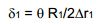
[083] Conforme mostrado na Figura 14, a conformação do elemento flexível primário 255 pode ser semelhante à conformação dos elementos flexíveis secundários 254 e 255, de modo que R1/Δr1 = R2/Δr2. Portanto, uma vez que o elemento fle-xível primário é mecanicamente unido ao alojamento 240 e ao tubo de extensão 234 em paralelo com a combinação em série dos elementos flexíveis superiores e inferiores 254, 255, o deslocamento angular (θ) do tubo de extensão 235 com relação ao alojamento 240 em volta do centro de rotação comum 243 provoca uma deformação angular (ô1) de cada um dos elementos flexíveis secundários que é de cerca da metade da deformação angular (ô2) do elemento flexível primário 241. Assim, cada um dos elementos flexíveis secundários pode ter as mesmas composição e construção e uma conformação semelhante à do elemento flexível primário 241, mas cada um dos elementos flexíveis secundários terá uma deformação angular (ô1) que é subs tancialmente menor que a deformação angular (δz) do elemento flexível primário 241. Um argumento semelhante, aplicado a deslocamentos axiais, mostra que os elementos flexíveis secundários 254, 255 se deslocam substancialmente menos que o tubo de extensão 234 ou o elemento flexível primário 241. Consequentemente, os elementos flexíveis secundários 254, 255 podem ser submetidos a uma carga de pressão ou temperatura mais elevada que a do elemento flexível primário 241 sem reduzir significativamente a vida útil de serviço da junta de tubo flexível 230.[083] As shown in Figure 14, the shaping of the primary
[084] Nas Figuras 12 e 14, por exemplo, o corpo cilíndrico 232 é perfurado para permitir que a água passe através do corpo cilíndrico 232 para resfriamento dos elementos flexíveis 241, 254, 255, e os elementos flexíveis secundários 254, 255 estão mais próximos do canal central do tubo de extensão 234 e do tubo interno 251, de modo que os elementos flexíveis secundários 254, 255 sejam submetidos a uma temperatura mais elevada do fluido de produção quente que a do elemento flexível primário 241. Além disto, os elementos flexíveis secundários 254, 255 vedam a pressão dentro do tubo de extensão 234, e o elemento flexível primário 255 não é submetido a esta pressão. Para uma aplicação, a espessura (Δri) dos elementos flexíveis secundários 254, 255 pode ser selecionado de modo que a deformação angular(δi) dos elementos flexíveis secundários seja reduzida com relação à deformação angular (δ2) do elemento flexível primário 24i em um grau apenas suficiente para lidar com a carga de pressão ou temperatura sobre os elementos flexíveis secundários com relação ao elemento flexível primário. Além do mais, a tensão axial sobre o tubo de extensão 234 põe os elementos flexíveis secundários 254, 255 em compressão, de modo que os elementos flexíveis secundários contribuem também para a capacidade da junta de tubo flexível 230 de lidar com um nível elevado de tensão axial sobre o tubo de extensão 234.[084] In Figures 12 and 14, for example, the
[085] De modo a se reduzir a carga de temperatura sobre os elementos flexíveis secundários 254, 255, a unidade de isolamento de pressão 250 inclui um in- serto de barreira térmica superior 256 disposto na extremidade alargada inferior 245 do tubo interno 25i e um inserto de barreira térmica inferior 257 disposto na extre- midade alargada superior 246 do inserto 252 do tubo de extensão. Os insertos de barreira térmica 256, 257 são feitos de um material de baixa condutividade térmica, tal como uma liga de níquel-ferro-cromo ou a poli-éter-éter-cetona. Os insertos de barreira térmica 256, 257 formam também uma junta de esfera e soquete dentro do anel centralizador 258.[085] In order to reduce the temperature load on the secondary
[086] O anel centralizador 253 é dividido na metade superior hemisférica 258 e na metade inferior hemisférica 159, de modo que as metades do anel centralizador possam ser soldadas uma na outra em volta dos insertos de barreira térmica 256, 257 após a moldagem dos elementos flexíveis secundários 254, 255. Quando o elemento flexível secundário superior 254 é moldado, o elastômero do elemento flexível secundário superior 254 torna-se ligado à metade superior 258 do anel centralizador e ligado ao flange inferior 245 do tubo interno 251. Quando o elemento flexívelsecundário inferior 255 é moldado, o elastômero do elemento flexível secundário inferior 255 torna-se ligado à metade inferior 259 do anel centralizador 253 e ligado ao flange superior 246 do inserto 252 do tubo de extensão. Em seguida, o inserto de barreira térmica superior 256 é inserido no tubo interno 251, e o inserto de barreira térmica inferior 257 é inserido no inserto 252 do tubo de extensão. Em seguida, o inserto de barreira térmica superior 256 é inserido no inserto de barreira térmica inferior 257 de modo que a metade superior 258 do anel centralizador 253 fique casada com a metade inferior 259 do anel centralizador e soldada na metade inferior do anel centralizador, formando a solda 260.[086] The centering
[087] Quando o elemento flexível primário 241 é moldado, o elastômero do elemento flexível primário torna-se ligado ao anel de sustentação inferior 231 e ligado ao flange 242 do invólucro externo 235 do tubo de extensão 234. Em seguida, o inserto 252 do tubo de extensão é inserido no invólucro 235 do tubo de extensão de modo que o sistema de isolamento de pressão 250 seja assentado sobre o invólucro 235 do tubo de extensão. Em seguida, o corpo cilíndrico 232 é colocado sobre o anel de sustentação inferior 231, e o flange de fixação 233 é encaixado sobre o tubo interno 251 e sobre o corpo cilíndrico 232. Em seguida, as cavilhas 249 são aperta- das para prender o flange de fixação 233 ao corpo cilíndrico 232. Finalmente, o in- serto 252 do tubo de extensão é soldado no invólucro 235 do tubo de extensão, e o tubo interno 251 é soldado no flange de fixação 233.[087] When the primary
[088] A Figura 15 mostra uma junta de tubo flexível 270 que é semelhante à junta de tubo flexível 230 da Figura 14, mas que inclui dois elementos flexíveis primários 281, 282 mecanicamente acoplados em paralelo para lidar com o aumento da carga axial para o alojamento de uma dada pegada. A junta de tubo flexível 270 da Figura 15 tem um alojamento 280 e um tubo de extensão 274 que se estende a partir do alojamento 280. A alojamento 280 inclui um anel de sustentação inferior 271, um corpo cilíndrico 272 e um flange de fixação 273. O tubo de extensão 274 é constituído por um revestimento interno de tubo de extensão 275 e de um invólucro de tubo de extensão 284 soldado no revestimento interno de tubo de extensão 275.[088] Figure 15 shows a flexible tube joint 270 that is similar to the flexible tube joint 230 of Figure 14, but which includes two primary
[089] Um elemento flexível elastomérico anular primário inferior 281 é disposto no alojamento 280 entre o anel de sustentação inferior 271 e um flange 285 do invólucro 284 do tubo de extensão. Um elemento flexível elastomérico anular primário superior 282 é disposto no alojamento 280 entre um anel de carga superior 287 e um flange 297 de um invólucro de tubo interno 286 soldado em um revestimento interno de tubo interno 291. O revestimento interno 291 do tubo interno é soldado n flange de fixação 273. O anel de carga superior 287 é preso, por uma série de cavilhas 303, ao flange 285 do invólucro 284 do tubo de extensão. Um elemento flexível elastomérico anular secundário inferior 293 é disposto no alojamento 280 entre a metade inferior 299 de um anel centralizador 292 e um flange superior 296 do revestimento interno 275 do tubo de extensão. Um elemento flexível elastomérico anular secundário superior 294 é disposto no alojamento 280 entre a metade superior 298 do anel centralizador 292 e o flange inferior 295 do revestimento interno 291 do tubo interno. A metade superior 298 do anel centralizador 292 é preso por uma solda equatorial 300 à metade inferior 299 do anel centralizador 292.[089] A lower primary annular elastomeric
[090] O elemento flexível secundário inferior 293, o elemento flexível secundário superior 294, o elemento flexível primário inferior 281 e o elemento flexível primário superior 282 têm um centro de rotação comum 283. O elemento flexível secundário inferior 293 e o elemento flexível secundário superior 294 são empilhados de maneira coaxial em lados opostos do centro de rotação comum 283, e o elementoflexível secundário inferior 293 e o elemento flexível secundário superior 294 são dispostos a partir do centro de rotação comum 283 por um raio interno comum (R1). O elemento flexível primário inferior 281 e o elemento flexível primário superior 282 são também empilhados de maneira coaxial em lados opostos do centro de rotação comum 283, e o elemento flexível primário inferior 281 e o elemento flexível primário superior 282 são dispostos a partir do centro de rotação comum 283 por um raio externo comum (R2). O raio externo (R2) é maior que o raio interno (R1).[090] The lower secondary
[091] Os elementos flexíveis secundários inferior e superior 293, 294 são mecanicamente unidos em série entre o alojamento 280 e o tubo de extensão 274. Cada um dos elementos flexível primário inferior 281 e elemento flexível primário superior 282 é mecanicamente unido ao alojamento 280 e ao tubo de extensão 274 em paralelo com a combinação em série dos elementos flexíveis inferior e superior 293, 294. Os elementos flexíveis superior e inferior 292, 294 têm praticamente as mesmas composição e conformação. Consequentemente, um deslocamento angular (θ) do tubo de extensão 274 com relação ao alojamento 280 em volta do centro de rotação comum 283 em volta do centro de rotação comum 283 que cerca da metade do deslocamento angular (θ) do tubo de extensão 274 com relação ao alojamento 280 em volta do centro de rotação comum 283.[091] The lower and upper secondary
[092] Os elementos flexíveis primários superior e inferior 281, 282 não precisam ter o mesmo tamanho e composição, mas os elementos flexíveis secundários 293, 294 serão usualmente das mesmas composição e conformação. A tensão axial sobre o tubo de extensão 274 com relação ao alojamento 280 cada um dos elementos flexíveis primários e secundários 281, 282, 293, 294 em compressão.[092] The upper and lower primary
[093] Uma vez que os elementos flexíveis primários 281, 282 são mecanicamente unidos em paralelo um ao outro, seus deslocamentos axial e angular serão os mesmos, e uma vez que os elementos flexíveis primários 281, 282 são mecani- camente unidos em paralelo um ao outro e em paralelo aos elementos flexíveis primários através do revestimento interno do tubo de extensão 275 do tubo de extensão 274, os deslocamentos axial e angular de cada elemento flexível secundário 293, 294 serão aproximadamente metade dos do revestimento interno 275 do tubo de extensão, ou do tubo de extensão 274, ou dos elementos flexíveis primários 281, 282. Esta característica de desenho permite o dimensionamento dos elementos flexíveis primários de modo a se portar uma grande parte da carga axial total resultante da tensão sobre o tubo de extensão 274 e a pressão do fluido que atua sobre o con-junto do elemento flexível secundário 293, ligado ao tubo de extensão 274, limitando assim o grau de compressão sobre as almofadas elastoméricos dos elementos flexíveissecundários 293, 294 e aumentando assim sua vida útil de serviço, e a da junta de tubo flexível 270.[093] Since the primary
[094] Um revestimento interno de blindagem térmica superior 301 é disposto no revestimento interno de tubo interno 291, e um revestimento interno de blindagemtérmica inferior 302 é disposto no revestimento interno 275 do tubo de extensão.[094] An upper thermal shield
[095] A Figura 16 mostra a junta de tubo flexível 270 após uma deflexão angular (θ) do tubo de extensão 274 de cerca de 20 graus com relação ao alojamento 280. A deflexão angular resultante (9) do anel centralizador 292 é de cerca de 10 graus. Versões dos elementos flexíveis primários e secundários 281, 282, 293, 294 sem deformação são mostradas em linhas esquemáticas para exibição da deformação angular resultante (ÔI) dos elementos flexíveis primários 281, 282. Portanto, é mostrado que a deformação angular resultante (ÔI) dos elementos flexíveis secundários 293, 294 é substancialmente menor que a deformação angular (ô2) dos elementos flexíveis primários 281, 282.[095] Figure 16 shows the flexible tube joint 270 after an angular deflection (θ) of the
[096] Em vista do exposto, foi descrita uma junta flexível que tem dois elementos flexíveis elastoméricos anulares empilhados de maneira coaxial a um raio interno de um centro de rotação comum, e pelo menos um elemento flexível elasto- mérico anular disposto a um raio externo a partir do centro de rotação comum. Os elementos flexíveis no raio interno são acoplados mecanicamente em série entre o tubo de extensão e o alojamento da junta de tubo flexível, e o elemento flexível no raio externo é acoplado em paralelo com a combinação em série dos elementos flexíveis no raio interno. Consequentemente, em um caso preferido dos dois elementos flexíveis no raio interno que têm aproximadamente o mesmo tamanho, conformação e construção, cada elemento flexível no raio interno tem um deslocamento angular que é cerca de metade do elemento flexível no raio externo. Portanto, os elementos flexíveis no raio interno podem portar cargas adicionais de pressão e calor.[096] In view of the foregoing, a flexible joint has been described having two annular elastomeric flexible elements stacked coaxially to an inner radius of a common center of rotation, and at least one annular elastomeric flexible element disposed at an outer radius from the common center of rotation. The flexible elements on the inner radius are mechanically coupled in series between the extension tube and the flexible tube joint housing, and the flexible element on the outer radius is coupled in parallel with the series combination of the flexible elements on the inner radius. Consequently, in a preferred case of the two flexible elements in the inner radius having approximately the same size, shape and construction, each flexible element in the inner radius has an angular displacement which is about half of the flexible element in the outer radius. Therefore, flexible elements in the inner radius can carry additional pressure and heat loads.
Claims (28)
Applications Claiming Priority (7)
| Application Number | Priority Date | Filing Date | Title |
|---|---|---|---|
| US12/036,738 US8016324B2 (en) | 2008-02-25 | 2008-02-25 | Two-element tandem flexible joint |
| US12/036,738 | 2008-02-25 | ||
| US12/036.738 | 2008-02-25 | ||
| US12/196,230 US8038177B2 (en) | 2008-02-25 | 2008-08-21 | Pressure isolation system for flexible pipe joints |
| US12/196,230 | 2008-08-21 | ||
| US12/196.230 | 2008-08-21 | ||
| PCT/US2009/035031 WO2009108644A1 (en) | 2008-02-25 | 2009-02-24 | Pressure isolation system for flexible pipe joints |
Publications (2)
| Publication Number | Publication Date |
|---|---|
| BRPI0901007A2 BRPI0901007A2 (en) | 2021-04-27 |
| BRPI0901007B1 true BRPI0901007B1 (en) | 2021-09-08 |
Family
ID=40722395
Family Applications (1)
| Application Number | Title | Priority Date | Filing Date |
|---|---|---|---|
| BRPI0901007-6A BRPI0901007B1 (en) | 2008-02-25 | 2009-02-24 | FLEXIBLE TUBE JOINTS |
Country Status (9)
| Country | Link |
|---|---|
| US (2) | US8038177B2 (en) |
| EP (1) | EP2142836B1 (en) |
| CN (1) | CN101680584B (en) |
| AU (1) | AU2009208133B8 (en) |
| BR (1) | BRPI0901007B1 (en) |
| ES (1) | ES2391929T3 (en) |
| MY (1) | MY151445A (en) |
| RU (1) | RU2477412C2 (en) |
| WO (1) | WO2009108644A1 (en) |
Families Citing this family (15)
| Publication number | Priority date | Publication date | Assignee | Title |
|---|---|---|---|---|
| US8038177B2 (en) | 2008-02-25 | 2011-10-18 | Oil States Industries, Inc. | Pressure isolation system for flexible pipe joints |
| US8016324B2 (en) * | 2008-02-25 | 2011-09-13 | Oil States Industries, Inc. | Two-element tandem flexible joint |
| US8128129B2 (en) * | 2009-07-15 | 2012-03-06 | Oil States Industries, Inc. | Double-ended flexible pipe joint having stacked co-axial primary and secondary annular elastomeric flex elements |
| US8833802B2 (en) | 2011-11-08 | 2014-09-16 | Oil States Industries, Inc. | Misaligned pipe connector |
| US9458877B2 (en) | 2013-01-24 | 2016-10-04 | The Boeing Company | Multi-directional elastomeric dampened ball joint assembly |
| US9957769B2 (en) | 2013-04-23 | 2018-05-01 | Lord Corporation | Elevated temperature riser bearing |
| CN103334703B (en) * | 2013-06-24 | 2015-08-05 | 宝鸡石油机械有限责任公司 | A kind of Offshore Drilling Riser two flexible device in middle part |
| FR3011903B1 (en) * | 2013-10-14 | 2016-01-01 | Techlam Sas | FLEXIBLE JOINT FOR HYDROCARBON PIPES, METHOD OF DETECTING LEAKAGE IN SUCH JOINT, AND SYSTEM FOR DETECTING HYDROCARBON LEAKAGE IN SUCH A SEAL. |
| US9822628B2 (en) | 2013-10-23 | 2017-11-21 | Halliburton Energy Services, Inc. | Sealing element wear detection for wellbore devices |
| EP2913268B1 (en) | 2014-02-26 | 2018-08-01 | AIRBUS HELICOPTERS DEUTSCHLAND GmbH | Bearing arrangement with a first bearing layer and a second bearing layer |
| CN104832738A (en) * | 2015-05-21 | 2015-08-12 | 中国平煤神马集团阳光物业有限公司 | Cylindrical hinge compensator |
| PT3303897T (en) | 2015-05-29 | 2019-05-23 | Oil States Ind Inc | Flexible pipe joint having an annular flexible boot thermally or chemically insulating an annular elastomeric flexible element |
| JP2022531124A (en) * | 2019-04-24 | 2022-07-06 | シングル・ブイ・ムーリングス・インコーポレイテッド | Swivel stacks for transferring fluid across a rotary interface and methods for manufacturing such swivel stacks. |
| US11274504B2 (en) | 2020-05-07 | 2022-03-15 | Subsea 7 Do Brasil Servicos Ltda | Top connections of subsea risers |
| CN114407373B (en) * | 2021-11-29 | 2023-09-01 | 中国海洋石油集团有限公司 | Flexible joint forming tool |
Family Cites Families (54)
| Publication number | Priority date | Publication date | Assignee | Title |
|---|---|---|---|---|
| US2900182A (en) | 1955-04-27 | 1959-08-18 | William L Hinks | Static load bearings |
| US3336054A (en) * | 1965-01-15 | 1967-08-15 | Mobil Oil Corp | Liner-carrying well pipe and joint |
| US3429622A (en) | 1967-03-06 | 1969-02-25 | Thiokol Chemical Corp | Flexible bearings and process for their manufacture |
| US3519260A (en) | 1967-08-22 | 1970-07-07 | Trw Inc | Flame and heat resistant resilient laminated bearing structure |
| US3555590A (en) | 1968-09-20 | 1971-01-19 | Holmes Hardware & Sales Co | Hardware and devices for adjusting the spring tension in a counterbalance hinging system |
| US3680895A (en) | 1969-11-24 | 1972-08-01 | Lockheed Aircraft Corp | Flexible joint means |
| US3734546A (en) * | 1972-03-30 | 1973-05-22 | Lockheed Aircraft Corp | Flexible pipe connection |
| US3941433A (en) | 1975-05-05 | 1976-03-02 | Thiokol Corporation | Flexible bearing having low torque resistance |
| US3958840A (en) | 1975-05-05 | 1976-05-25 | Thiokol Corporation | Flexible bearing having reinforcements |
| US4068868A (en) | 1975-09-02 | 1978-01-17 | Vetco Offshore Industries, Inc. | Flexible joints for marine risers |
| US4173360A (en) * | 1975-10-10 | 1979-11-06 | Lord Corporation | Flexible sealing joint |
| US4040690A (en) | 1975-11-17 | 1977-08-09 | Lord Corporation | Laminated bearing |
| US4068858A (en) * | 1976-01-09 | 1978-01-17 | Nelson K. Harrison | Bicycle |
| US4086864A (en) * | 1976-02-10 | 1978-05-02 | Hitachi Shipbuilding & Engineering Co., Ltd. | Support device for ship-carried independent tank |
| US4103939A (en) * | 1976-06-15 | 1978-08-01 | Murdock Machine & Engineering Company | Multi passage flexible connector |
| US4068864A (en) | 1976-06-30 | 1978-01-17 | Murdock Machine & Engineering Company | Single element flexible connection |
| US4081660A (en) | 1976-07-06 | 1978-03-28 | Baxter Travenol Laboratories, Inc. | Heater shutdown circuit |
| US4324194A (en) | 1976-12-10 | 1982-04-13 | Hydra-Rig, Inc. | Stabilized hoist rig for deep ocean mining vessel |
| US4098527A (en) | 1977-01-21 | 1978-07-04 | Murdock Machine & Engineering Company | Tension bearing connector |
| US4121861A (en) | 1977-04-29 | 1978-10-24 | Lord Corporation | Flexible sealing joint |
| US4183556A (en) * | 1977-04-29 | 1980-01-15 | Lord Corporation | Liquid filled flexible sealing joint |
| US4263243A (en) | 1979-05-07 | 1981-04-21 | Thiokol Corporation | Method for making a flexible bearing |
| FR2486621B1 (en) | 1980-07-11 | 1986-03-07 | Doris Dev Richesse Sous Marine | FLEXIBLE JOINT FOR THE CONNECTION OF TWO DUCTS |
| US4366971A (en) * | 1980-09-17 | 1983-01-04 | Allegheny Ludlum Steel Corporation | Corrosion resistant tube assembly |
| US4570979A (en) * | 1982-06-10 | 1986-02-18 | Dunlop Limited | Flexible joint means |
| US4515399A (en) | 1982-12-27 | 1985-05-07 | Lockheed Corporation | Symmetrically loaded flexible connector having multiple passageways |
| US4593941A (en) | 1984-03-15 | 1986-06-10 | Ltv Energy Products Company | Diverter flex joint |
| US4706998A (en) | 1984-12-05 | 1987-11-17 | Lockheed Corporation | Axial displacement coupling |
| US4759662A (en) | 1986-06-30 | 1988-07-26 | Lockheed Corporation | TLP marine riser tensioner |
| US4708758A (en) | 1986-09-25 | 1987-11-24 | Morton Thiokol, Inc. | Method of making a flexible bearing |
| US4984827A (en) | 1987-01-30 | 1991-01-15 | Lockheed Corporation | Concentric piping flex joint |
| US4784410A (en) | 1987-01-30 | 1988-11-15 | Lockheed Corporation | Concentric piping flex joint |
| US4797639A (en) | 1987-05-22 | 1989-01-10 | The United States Of America As Represented By The Secretary Of The Air Force | Low noise crystal controlled oscillator |
| US5133578A (en) | 1991-03-08 | 1992-07-28 | Ltv Energy Products Company | Flexible joint with non-diffusive barrier |
| US5269629A (en) | 1991-07-29 | 1993-12-14 | Shell Oil Company | Elastomeric swivel support assembly for catenary riser |
| US5482406A (en) | 1993-04-15 | 1996-01-09 | Continental Emsco Company | Variable spring rate compression element and riser tensioner system using the same |
| US5641248A (en) | 1993-04-15 | 1997-06-24 | Continental Emsco Company | Variable spring rate compression element and riser tensioner system using the same |
| US5615977A (en) | 1993-09-07 | 1997-04-01 | Continental Emsco Company | Flexible/rigid riser system |
| US5791695A (en) | 1995-04-18 | 1998-08-11 | Continental Emsco Co. | Flexible joint for facilitating bending of tubular segments |
| CN2273799Y (en) * | 1996-08-29 | 1998-02-04 | 王力人 | Flexible connection structure for metallic tube |
| US5905212A (en) | 1997-06-04 | 1999-05-18 | Continental Emsco Company | Load and deflection measurement system for elastomeric bearings |
| US5951061A (en) | 1997-08-13 | 1999-09-14 | Continental Emsco Company | Elastomeric subsea flex joint and swivel for offshore risers |
| RU2195601C2 (en) * | 1998-12-07 | 2002-12-27 | Открытое акционерное общество Научно-производственное объединение "Искра" | Method for making flexible movable joint |
| US6739804B1 (en) | 1999-04-21 | 2004-05-25 | Ope, Inc. | SCR top connector |
| US6789790B2 (en) | 2002-06-18 | 2004-09-14 | Frank H. Speckhart | Helical coil spring damper assembly |
| US7241283B2 (en) * | 2003-04-25 | 2007-07-10 | Ad-Tech Medical Instrument Corp. | Method for intracranial catheter treatment of brain tissue |
| DE10328717B3 (en) | 2003-06-25 | 2004-12-02 | Eads Deutschland Gmbh | Operating device for control flap on rear edge of aircraft wing has pyramid transmission device connected on one side to wing structure and on other to flap |
| US7341283B2 (en) | 2004-01-29 | 2008-03-11 | Oil States Industries, Inc. | High temperature flexible pipe joint |
| US7167412B2 (en) | 2004-12-17 | 2007-01-23 | Pgs Americas, Inc. | Apparatus for steering a marine seismic streamer via controlled bending |
| TWM318751U (en) | 2007-03-16 | 2007-09-11 | Cooler Master Co Ltd | Heat dissipating device able to connect in series with water-cooled circulation system |
| US20090156341A1 (en) | 2007-12-14 | 2009-06-18 | John Gaynor | Belt |
| US8038177B2 (en) | 2008-02-25 | 2011-10-18 | Oil States Industries, Inc. | Pressure isolation system for flexible pipe joints |
| US8016324B2 (en) | 2008-02-25 | 2011-09-13 | Oil States Industries, Inc. | Two-element tandem flexible joint |
| US8128129B2 (en) | 2009-07-15 | 2012-03-06 | Oil States Industries, Inc. | Double-ended flexible pipe joint having stacked co-axial primary and secondary annular elastomeric flex elements |
-
2008
- 2008-08-21 US US12/196,230 patent/US8038177B2/en active Active
-
2009
- 2009-02-24 MY MYPI20093455 patent/MY151445A/en unknown
- 2009-02-24 AU AU2009208133A patent/AU2009208133B8/en active Active
- 2009-02-24 CN CN2009800001853A patent/CN101680584B/en active Active
- 2009-02-24 ES ES09715455T patent/ES2391929T3/en active Active
- 2009-02-24 RU RU2010134826/06A patent/RU2477412C2/en active
- 2009-02-24 WO PCT/US2009/035031 patent/WO2009108644A1/en active Application Filing
- 2009-02-24 EP EP09715455A patent/EP2142836B1/en active Active
- 2009-02-24 BR BRPI0901007-6A patent/BRPI0901007B1/en active IP Right Grant
-
2011
- 2011-08-25 US US13/218,402 patent/US8985636B2/en active Active
Also Published As
| Publication number | Publication date |
|---|---|
| CN101680584B (en) | 2011-06-08 |
| US8985636B2 (en) | 2015-03-24 |
| AU2009208133A1 (en) | 2009-09-10 |
| EP2142836A1 (en) | 2010-01-13 |
| EP2142836B1 (en) | 2012-08-01 |
| BRPI0901007A2 (en) | 2021-04-27 |
| RU2010134826A (en) | 2012-04-10 |
| WO2009108644A1 (en) | 2009-09-03 |
| AU2009208133B2 (en) | 2011-01-20 |
| US20090212558A1 (en) | 2009-08-27 |
| RU2477412C2 (en) | 2013-03-10 |
| MY151445A (en) | 2014-05-30 |
| CN101680584A (en) | 2010-03-24 |
| US8038177B2 (en) | 2011-10-18 |
| AU2009208133B8 (en) | 2011-01-27 |
| US20120032434A1 (en) | 2012-02-09 |
| ES2391929T3 (en) | 2012-12-03 |
Similar Documents
| Publication | Publication Date | Title |
|---|---|---|
| BRPI0901007B1 (en) | FLEXIBLE TUBE JOINTS | |
| US8157295B2 (en) | Articulating joint with injector port | |
| US4415184A (en) | High temperature insulated casing | |
| US7341283B2 (en) | High temperature flexible pipe joint | |
| US11105175B2 (en) | Adjustable frac flow line | |
| US8016324B2 (en) | Two-element tandem flexible joint | |
| BRPI1003400A2 (en) | lifting pipe with auxiliary rigid pin-mounted lines | |
| BR112012021133B1 (en) | CONNECTOR FOR ASSEMBLING TWO SECTIONS OF ASCENDING TUBE AND ASCENDING TUBE | |
| BR112014032236B1 (en) | METHOD, ASSEMBLY AND KIT OF PARTS FOR TESTING THE INTEGRITY OF A FLEXIBLE PIPE SEALING RING | |
| EP2989287B1 (en) | Elevated temperature riser bearing | |
| BR112013000292B1 (en) | rotating fluid joint, anchoring tower structure, vessel and method for replacing an outer annular ring of a rotating fluid joint | |
| US9022125B2 (en) | Marine riser with side tension members | |
| CA2657170C (en) | Articulating joint with injector port | |
| CN105465530B (en) | Pressure-balancing type sleeve expansion joint | |
| BR112020025351A2 (en) | tubular joint and installation | |
| GB2609980A (en) | Marine riser with support device for riser buoyancy module | |
| BR112014032203B1 (en) | METHOD FOR TESTING AND ASSEMBLY TO ENSURE THE INTEGRITY OF A FLEXIBLE PIPE SEALING ARRANGEMENT | |
| CN106090515A (en) | A kind of low-voltage high-temperature restricted type expansion joint floating installation | |
| EP3282085A1 (en) | A hydrocarbon production system |
Legal Events
| Date | Code | Title | Description |
|---|---|---|---|
| B06F | Objections, documents and/or translations needed after an examination request according [chapter 6.6 patent gazette] | ||
| B06U | Preliminary requirement: requests with searches performed by other patent offices: procedure suspended [chapter 6.21 patent gazette] | ||
| B09A | Decision: intention to grant [chapter 9.1 patent gazette] | ||
| B16A | Patent or certificate of addition of invention granted [chapter 16.1 patent gazette] |
Free format text: PRAZO DE VALIDADE: 20 (VINTE) ANOS CONTADOS A PARTIR DE 24/02/2009, OBSERVADAS AS CONDICOES LEGAIS. PATENTE CONCEDIDA CONFORME ADI 5.529/DF, QUE DETERMINA A ALTERACAO DO PRAZO DE CONCESSAO. |