BRPI0813909B1 - SYRINGE SET WITH A PASSIVE DISPOSAL SYSTEM - Google Patents
SYRINGE SET WITH A PASSIVE DISPOSAL SYSTEM Download PDFInfo
- Publication number
- BRPI0813909B1 BRPI0813909B1 BRPI0813909-1A BRPI0813909A BRPI0813909B1 BR PI0813909 B1 BRPI0813909 B1 BR PI0813909B1 BR PI0813909 A BRPI0813909 A BR PI0813909A BR PI0813909 B1 BRPI0813909 B1 BR PI0813909B1
- Authority
- BR
- Brazil
- Prior art keywords
- cap
- cylinder
- piston rod
- syringe
- proximal end
- Prior art date
Links
Images


Classifications
-
- A—HUMAN NECESSITIES
- A61—MEDICAL OR VETERINARY SCIENCE; HYGIENE
- A61M—DEVICES FOR INTRODUCING MEDIA INTO, OR ONTO, THE BODY; DEVICES FOR TRANSDUCING BODY MEDIA OR FOR TAKING MEDIA FROM THE BODY; DEVICES FOR PRODUCING OR ENDING SLEEP OR STUPOR
- A61M5/00—Devices for bringing media into the body in a subcutaneous, intra-vascular or intramuscular way; Accessories therefor, e.g. filling or cleaning devices, arm-rests
- A61M5/50—Devices for bringing media into the body in a subcutaneous, intra-vascular or intramuscular way; Accessories therefor, e.g. filling or cleaning devices, arm-rests having means for preventing re-use, or for indicating if defective, used, tampered with or unsterile
- A61M5/5066—Means for preventing re-use by disconnection of piston and piston-rod
-
- A—HUMAN NECESSITIES
- A61—MEDICAL OR VETERINARY SCIENCE; HYGIENE
- A61M—DEVICES FOR INTRODUCING MEDIA INTO, OR ONTO, THE BODY; DEVICES FOR TRANSDUCING BODY MEDIA OR FOR TAKING MEDIA FROM THE BODY; DEVICES FOR PRODUCING OR ENDING SLEEP OR STUPOR
- A61M5/00—Devices for bringing media into the body in a subcutaneous, intra-vascular or intramuscular way; Accessories therefor, e.g. filling or cleaning devices, arm-rests
- A61M5/50—Devices for bringing media into the body in a subcutaneous, intra-vascular or intramuscular way; Accessories therefor, e.g. filling or cleaning devices, arm-rests having means for preventing re-use, or for indicating if defective, used, tampered with or unsterile
- A61M5/5013—Means for blocking the piston or the fluid passageway to prevent illegal refilling of a syringe
- A61M5/502—Means for blocking the piston or the fluid passageway to prevent illegal refilling of a syringe for blocking the piston
-
- A—HUMAN NECESSITIES
- A61—MEDICAL OR VETERINARY SCIENCE; HYGIENE
- A61M—DEVICES FOR INTRODUCING MEDIA INTO, OR ONTO, THE BODY; DEVICES FOR TRANSDUCING BODY MEDIA OR FOR TAKING MEDIA FROM THE BODY; DEVICES FOR PRODUCING OR ENDING SLEEP OR STUPOR
- A61M5/00—Devices for bringing media into the body in a subcutaneous, intra-vascular or intramuscular way; Accessories therefor, e.g. filling or cleaning devices, arm-rests
- A61M5/178—Syringes
- A61M5/31—Details
- A61M5/315—Pistons; Piston-rods; Guiding, blocking or restricting the movement of the rod or piston; Appliances on the rod for facilitating dosing ; Dosing mechanisms
- A61M5/31511—Piston or piston-rod constructions, e.g. connection of piston with piston-rod
- A61M2005/31516—Piston or piston-rod constructions, e.g. connection of piston with piston-rod reducing dead-space in the syringe barrel after delivery
-
- A—HUMAN NECESSITIES
- A61—MEDICAL OR VETERINARY SCIENCE; HYGIENE
- A61M—DEVICES FOR INTRODUCING MEDIA INTO, OR ONTO, THE BODY; DEVICES FOR TRANSDUCING BODY MEDIA OR FOR TAKING MEDIA FROM THE BODY; DEVICES FOR PRODUCING OR ENDING SLEEP OR STUPOR
- A61M5/00—Devices for bringing media into the body in a subcutaneous, intra-vascular or intramuscular way; Accessories therefor, e.g. filling or cleaning devices, arm-rests
- A61M5/50—Devices for bringing media into the body in a subcutaneous, intra-vascular or intramuscular way; Accessories therefor, e.g. filling or cleaning devices, arm-rests having means for preventing re-use, or for indicating if defective, used, tampered with or unsterile
- A61M5/5013—Means for blocking the piston or the fluid passageway to prevent illegal refilling of a syringe
- A61M5/502—Means for blocking the piston or the fluid passageway to prevent illegal refilling of a syringe for blocking the piston
- A61M2005/5026—Means for blocking the piston or the fluid passageway to prevent illegal refilling of a syringe for blocking the piston allowing single filling of syringe
-
- A—HUMAN NECESSITIES
- A61—MEDICAL OR VETERINARY SCIENCE; HYGIENE
- A61M—DEVICES FOR INTRODUCING MEDIA INTO, OR ONTO, THE BODY; DEVICES FOR TRANSDUCING BODY MEDIA OR FOR TAKING MEDIA FROM THE BODY; DEVICES FOR PRODUCING OR ENDING SLEEP OR STUPOR
- A61M5/00—Devices for bringing media into the body in a subcutaneous, intra-vascular or intramuscular way; Accessories therefor, e.g. filling or cleaning devices, arm-rests
- A61M5/50—Devices for bringing media into the body in a subcutaneous, intra-vascular or intramuscular way; Accessories therefor, e.g. filling or cleaning devices, arm-rests having means for preventing re-use, or for indicating if defective, used, tampered with or unsterile
- A61M5/5066—Means for preventing re-use by disconnection of piston and piston-rod
- A61M2005/5073—Means for preventing re-use by disconnection of piston and piston-rod by breaking or rupturing the connection parts
Abstract
?seringa com mecanismo de inutilização. são fornecidas estruturas de seringa com um sistema passivo de inutilização para evitar a reutilização. em uma modalidade, o sistema passivo de inutilização ativa-se apés a conclusão de um ciclo de injeção. uma estrutura de seringa exemplar incorpora um tampão e haste de êmbolo acoplados de forma a impedir que os usuários desmontem a seringa antes da conclusão do ciclo de injeção. o cilindro pode também incluir uma extenso anular ou colar que se estende da extremidade proximal do cilindro. em uma configuração especifica, a extenso anular envolve, pelo menos parcialmente, uma por¢do da válvula de pressão para impedir que o usuário acesse a válvula de pressão e mova a haste do êmbolo em uma direção proximal. estruturas de seringa de uma ou mais modalidades também incluem indicadores visuais ou marcadores que indicam se uma estrutura de seringa é usada ou o se a haste do êmbolo esta trancada dentro do cilindro.?syringe with disabling mechanism. syringe structures with a passive discard system are provided to prevent reuse. in one modality, the passive disable system activates upon completion of an injection cycle. an exemplary syringe structure incorporates a coupled plunger cap and rod to prevent users from disassembling the syringe prior to completion of the injection cycle. the cylinder may also include an annular extension or collar that extends from the proximal end of the cylinder. in a specific configuration, the annular extension at least partially surrounds a portion of the pressure valve to prevent the user from accessing the pressure valve and moving the piston rod in a proximal direction. Syringe structures of one or more embodiments also include visual indicators or markers that indicate whether a syringe structure is used or whether the plunger rod is locked within the cylinder.
Description
[001] Este pedido reivindica o benefício de prioridade para o Pedido Provisório U.S. N° 60/943.397, depositado em 12 de junho de 2007, a descrição do qual é aqui incorporada em sua totalidade para referência ao mesmo.[001] This application claims priority benefit to U.S. Provisional Application No. 60/943,397, filed June 12, 2007, the description of which is incorporated herein in its entirety by reference thereto.
[002] A presente invenção refere-se a conjuntos de seringa com um mecanismo passivo de inutilização que restringe a remoção da haste de êmbolo após a injeção para impedir a reutilização, conjuntos de seringa em que o tampão e a haste de êmbolo funcionam utilizando movimento relativo para passivamente inutilizar a seringa, conjuntos de seringa incluindo um tampão e haste de êmbolo removivel- mente conectados para impedir a desmontagem da seringa antes da utilização a conjuntos de seringa incluindo indicação ou marcações visuais para indicar a utilização da seringa ou uma seringa inutilizada.[002] The present invention relates to syringe assemblies with a passive disabling mechanism that restricts the removal of the plunger rod after injection to prevent reuse, syringe assemblies in which the cap and plunger rod operate using movement relative to passively disable the syringe, syringe assemblies including a removable plug and plunger rod to prevent disassembly of the syringe prior to use to syringe assemblies including visual indications or markings to indicate use of the syringe or an unused syringe.
[003] Acredita-se que a reutilização de produtos de seringa hipodérmica sem esterilização ou esterilização suficiente perpetue o abuso de drogas e facilite a transmissão de doenças contagiosas. A reutilização de seringas por usuários de drogas intravenosas agrava a transmissão de doenças contagiosas, porque estes constituem um grupo de alto risco com relação a certos vírus, tais como o vírus da Aids e hepatite. Um alto risco de contaminação também existe em países com escassez de médicos e de suprimentos.[003] It is believed that the reuse of hypodermic syringe products without sterilization or sufficient sterilization perpetuates drug abuse and facilitates the transmission of contagious diseases. The reuse of syringes by intravenous drug users aggravates the transmission of contagious diseases, because they constitute a high-risk group with respect to certain viruses, such as the AIDS and hepatitis viruses. A high risk of contamination also exists in countries with shortages of doctors and supplies.
[004] Uma seringa que possa ser inutilizada após a sua utilização apresenta uma solução viável para estas questões. Várias seringas têm sido propostas e estão disponíveis comercialmente, as quais podem ser inutilizadas pelo usuário, tomando medidas ativas para inutilizar a seringa. Seringas de uso único que não exigem que o usuário ativamente inutilize a seringa também são pensadas para oferecer uma solução. Seria desejável fornecer seringas que fossem automaticamente ou passi- vamente inutilizadas para reutilização e que pudessem ser fabricadas de maneira custo-efetiva, por exemplo, utilizando menos peças. Além disso, marcadores ou outros indicadores visuais que indicam se uma seringa foi utilizada ou está inutilizada também seriam desejáveis.[004] A syringe that can be rendered useless after use presents a viable solution to these issues. Several syringes have been proposed and are commercially available, which can be discarded by the user, taking active measures to discard the syringe. Single-use syringes that do not require the user to actively disable the syringe are also thought to provide a solution. It would be desirable to provide syringes that are automatically or passively scrapped for reuse and that can be manufactured cost-effectively, for example, using fewer parts. In addition, markers or other visual indicators that indicate whether a syringe has been used or is no longer used would also be desirable.
[005] A presente invenção fornece um sistema passivo de inutilização para um conjunto de seringa, que é ativado após a conclusão de um ciclo de injeção. De acordo com uma ou mais modalidades da invenção, um conjunto de seringa incorpora um tampão e haste de êmbolo acoplados de forma a impedir que os usuários desmontem a seringa antes da conclusão do ciclo de injeção. Assim, um meio para impedir a remoção de uma haste de êmbolo de um conjunto de seringa é fornecido. Um usuário de tal seringa pode encher, injetar e / ou reconstituir medicação.[005] The present invention provides a passive disabling system for a syringe assembly, which is activated upon completion of an injection cycle. In accordance with one or more embodiments of the invention, a syringe assembly incorporates a plug and plunger rod coupled to prevent users from disassembling the syringe prior to completion of the injection cycle. Thus, a means for preventing removal of a plunger rod from a syringe assembly is provided. A user of such a syringe can fill, inject and/or reconstitute medication.
[006] Nesta descrição, uma convenção é seguida em que a extremidade distal do dispositivo é a extremidade mais próxima a um paciente e a extremidade proximal do dispositivo é a extremidade distante do paciente e mais próxima de um técnico.[006] In this description, a convention is followed in which the distal end of the device is the end closest to a patient and the proximal end of the device is the end distal to the patient and closest to a technician.
[007] Um conjunto de seringa é fornecido que inclui um cilindro, uma haste de êmbolo alongada com uma válvula de pressão e um tampão com respectivas estruturas e conjunto, que permite ao usuário restringir o acesso de forma passiva ou remover a haste de êmbolo do cilindro para evitar a reutilização do conjunto de seringa. O cilindro inclui uma extremidade distal, uma extremidade aberta proximal, uma parede lateral cilíndrica, que define uma câmara em que fluido pode ser mantido, e uma parede distal. Uma abertura na parede distal permite o fluxo de líquidos da câmara através da abertura. O cilindro pode também incluir uma extensão anular ou colar que se estende da extremidade proximal do cilindro. A extensão anular pode ter um diâmetro maior do que o diâmetro do êmbolo e da válvula de pressão que é conectada à haste de êmbolo. Como será mais bem descrito aqui, a extensão anular fornece um meio para impedir a remoção da haste de êmbolo do cilindro após a utilização. Em uma modalidade, o cilindro inclui um marcador ou indicador que indica se a seringa foi inutilizada ou o se êmbolo foi travado dentro do cilindro.[007] A syringe assembly is provided that includes a cylinder, an elongated plunger rod with a pressure valve and a cap with respective structures and assembly, which allows the user to passively restrict access or remove the plunger rod from the cylinder to prevent reuse of the syringe assembly. The cylinder includes a distal end, a proximal open end, a cylindrical side wall, which defines a chamber in which fluid can be held, and a distal wall. An opening in the distal wall allows fluid to flow from the chamber through the opening. The cylinder may also include an annular extension or collar that extends from the proximal end of the cylinder. The annular extension may have a larger diameter than the diameter of the plunger and pressure valve that is connected to the plunger rod. As will be further described here, the annular extension provides a means to prevent removal of the piston rod from the cylinder after use. In one embodiment, the cylinder includes a marker or indicator that indicates whether the syringe has been disabled or the plunger has been locked into the cylinder.
[008] Em uma ou mais modalidades, a parede lateral do cilindro tem um diâmetro contínuo ou primeiro diâmetro interno. Como utilizado ao longo deste pedido, o termo “diâmetro" é uma medida da maior distância entre as paredes do cilindro em forma transversal. No entanto, será apreciado que seringas convencionais são tipicamente cilíndricas em forma circular transversal. De acordo com uma ou mais modalidades da presente invenção, o cilindro inclui uma nervura, nervura de travamento ou qualquer outro impedimento adequado para restringir os movimentos proximal da haste de êmbolo, adjacente à sua extremidade proximal.[008] In one or more embodiments, the sidewall of the cylinder has a continuous diameter or first inside diameter. As used throughout this application, the term "diameter" is a measure of the greatest distance between the cylinder walls in transverse shape. However, it will be appreciated that conventional syringes are typically cylindrical in transverse circular shape. According to one or more embodiments of the present invention, the cylinder includes a rib, locking rib or any other suitable impediment to restrict the proximal movement of the piston rod adjacent its proximal end.
[009] Modalidades da presente invenção também incluem uma haste de êmbolo estendida que tem uma extremidade proximal, uma extremidade distal, e um corpo principal entre a extremidade proximal e distal. Em uma ou mais modalidades, a haste de êmbolo desliza ou de outra forma se move proximal e distalmente dentro da câmara do cilindro. Uma válvula de pressão é acoplada à extremidade proximal do êmbolo. A válvula de pressão inclui uma extremidade proximal e uma extremidade distal e, em uma ou mais modalidades, inclui um diâmetro que pode variar da extremidade distal para a extremidade proximal. Em uma modalidade específica, o diâmetro da válvula de pressão diminui da extremidade distal para a extremidade proximal.[009] Embodiments of the present invention also include an extended plunger rod having a proximal end, a distal end, and a main body between the proximal and distal end. In one or more embodiments, the plunger rod slides or otherwise moves proximally and distally within the cylinder chamber. A pressure valve is attached to the proximal end of the plunger. The pressure valve includes a proximal end and a distal end and, in one or more embodiments, includes a diameter that can vary from the distal end to the proximal end. In a specific modality, the pressure valve diameter decreases from the distal end to the proximal end.
[010] Em algumas modalidades, a extremidade distal do êmbolo inclui uma porção de engate do tampão com uma extremidade distal e proximal. A porção de engate do tampão de tais modalidades fornece um meio para a o tampão e a haste de êmbolo moverem-se proximal e distalmente dentro do cilindro. A porção de engate do tampão permite que o tampão e a haste de êmbolo se movam proximal e dis- talmente um em relação ao outro. O tampão pode se mover uma distância axial pré- selecionada em relação à porção de engate do tampão da haste de êmbolo. Em uma modalidade específica, porção de engate do tampão pode incluir uma borda em sua extremidade distal, um retentor ou meios alternativos adequados para restringir o tampão. A porção de engate do tampão, de acordo com uma ou mais modalida- des, pode incluir também um indicador visual ou um display que indique a utilização da seringa ou se a seringa está inutilizada.[010] In some embodiments, the distal end of the plunger includes a plug engaging portion with a distal and proximal end. The plug engaging portion of such embodiments provides a means for the plug and piston rod to move proximally and distally within the cylinder. The engagement portion of the cap allows the cap and plunger rod to move proximally and distally with respect to each other. The cap can move a preselected axial distance with respect to the cap engaging portion of the piston rod. In a specific embodiment, the engagement portion of the plug may include an edge at its distal end, a retainer, or suitable alternative means for restraining the plug. The engagement portion of the plug, according to one or more arrangements, may also include a visual indicator or a display that indicates use of the syringe or whether the syringe is unused.
[011] Em uma modalidade alternativa, o tampão e a haste de êmbolo são conectados de forma que se movam distalmente e proximalmente dentro do cilindro em uma relação fixa. Em tais modalidades, quando um usuário injeta todo o conteúdo do conjunto de seringa, o tampão e a haste de êmbolo se movem distalmente dentro do êmbolo até que o tampão alcance a parede distal e a válvula de pressão se move dentro do cilindro e / ou da extensão anular.[011] In an alternative embodiment, the cap and the piston rod are connected so that they move distally and proximally within the cylinder in a fixed relationship. In such embodiments, when a user injects the entire contents of the syringe assembly, the cap and plunger rod move distally within the plunger until the cap reaches the distal wall and the pressure valve moves within the cylinder and/or of the ring extension.
[012] De acordo com uma ou mais modalidades, a haste de êmbolo inclui ainda um meio para travar a haste de êmbolo no cilindro para impedir a reutilização do conjunto de seringa quando a seringa é totalmente injetada ou "assentada". Os meios podem ter um diâmetro externo maior do que o diâmetro interno do cilindro na nervura ou o segundo o diâmetro interno. Conforme utilizado aqui, o termo "assentado" refere-se à posição do conjunto de seringa em que o tampão, quando acoplado à haste de êmbolo, está em contato com a parede distal do cilindro e a haste de êmbolo não pode continuar a mover-se na direção distal. Um ou mais modalidades da presente invenção utilizam uma protusão ou protrusão anular que se estende radialmente a partir da haste de êmbolo. Em algumas modalidades, a protusão está localizada entre a válvula de pressão e o corpo principal, como um exemplo de um meio para travar a haste de êmbolo no cilindro. De acordo com uma modalidade da invenção, a protusão é moldada integralmente à haste de êmbolo.[012] In accordance with one or more embodiments, the plunger rod further includes a means for locking the plunger rod into the cylinder to prevent reuse of the syringe assembly when the syringe is fully injected or "seated". The means may have an outer diameter greater than the inner diameter of the cylinder in the rib or the second inner diameter. As used herein, the term "seated" refers to the position of the syringe assembly where the cap, when coupled to the plunger rod, is in contact with the distal wall of the cylinder and the plunger rod cannot continue to move. if in the distal direction. One or more embodiments of the present invention utilize an annular protrusion or protrusion that extends radially from the piston rod. In some embodiments, the protrusion is located between the pressure valve and the main body, as an example of a means for locking the piston rod into the cylinder. According to an embodiment of the invention, the protrusion is integrally molded to the piston rod.
[013] Em uma modalidade específica, a protrusão pode ter um diâmetro externo maior do que o segundo diâmetro interno. Nesta configuração específica, uma vez que a protrusão move-se distalmente após a nervura e para o cilindro, esta se torna bloqueada por uma nervura, impedindo assim o movimento proximal da haste de êmbolo. A protrusão pode ser cilíndrica ou de outra forma moldada, de modo tal que possa se mover na direção distal após a nervura com mais facilidade.[013] In a specific modality, the protrusion may have an outer diameter larger than the second inner diameter. In this particular configuration, as the protrusion moves distally past the rib and into the cylinder, it becomes blocked by a rib, thus preventing proximal movement of the piston rod. The protrusion can be cylindrical or otherwise shaped so that it can move distally past the rib more easily.
[014] O tampão tem uma extremidade proximal e uma extremidade distal, e o tampão é acoplado à porção de engate do tampão da haste de êmbolo. O tampão pode ainda compreender um corpo de tampão ou ressalto do tampão na extremidade proximal do tampão. Uma borda periférica pode ser incluída na extremidade proximal do corpo do tampão. Uma conexão de ruptura pode ser fornecida para conectar o tampão à haste de êmbolo, que pode conectar o tampão e a borda periférica.[014] The cap has a proximal end and a distal end, and the cap is coupled to the cap engaging portion of the plunger rod. The plug may further comprise a plug body or plug shoulder at the proximal end of the plug. A peripheral edge may be included at the proximal end of the tampon body. A break connection can be provided to connect the plug to the piston rod, which can connect the plug and the peripheral edge.
[015] Em modalidades onde o tampão se move distalmente e proximalmente em relação à porção de engate do tampão da haste de êmbolo, porção de engate do tampão da haste de êmbolo e o tampão podem ser conectados de forma tal que quando o usuário aplica um força no sentido proximal para aspiração ou preenchimento da seringa, o tampão permanece estacionário até que a haste de êmbolo se mova na direção proximal do comprimento da distância axial pré-selecionada. Em uma modalidade, quando um usuário continua a aspirar ou preencher o conjunto de seringa, o tampão começa a se mover na direção proximal em conjunto com a haste de êmbolo, após a haste de êmbolo ter percorrido a distância axial pré-selecionada no sentido proximal. Um indicador visual ou display opcional disposto na porção de engate do tampão da haste de êmbolo é visível quando o usuário preenche o conjunto de seringa.[015] In embodiments where the plug moves distally and proximally with respect to the engagement portion of the piston rod cap, the engagement portion of the piston rod cap and the cap can be connected in such a way that when the user applies a force in the proximal direction for aspiration or filling of the syringe, the stopper remains stationary until the plunger rod moves in the proximal direction of the length of the preselected axial distance. In one embodiment, when a user continues to aspirate or fill the syringe assembly, the cap begins to move in the proximal direction together with the plunger rod after the plunger rod has traveled the preselected axial distance in the proximal direction. . A visual indicator or optional display disposed on the engagement portion of the plunger rod cap is visible when the user fills the syringe assembly.
[016] Em uma ou mais modalidades em que o tampão pode mover-se em relação à porção de engate do tampão da haste de êmbolo, quando um usuário injeta o conteúdo do conjunto de seringa, o acoplamento do tampão e da porção de engate do tampão da haste de êmbolo permite que a haste de êmbolo se mova distalmente por um comprimento da distância axial pré-selecionada, enquanto o tampão permanece estacionário. Após a haste de êmbolo percorrer distalmente o comprimento da distância axial pré-selecionada, o tampão começa a se mover distalmente com a haste de êmbolo. Durante tal movimento distal, quando um indicador visual ou display é utilizado, o indicador visual ou display disposto na porção de engate do tampão da haste de êmbolo não é mais visível. Quando um marcador visual é utilizada, o marcador visual disposto no cilindro continua a ser visível, mesmo depois que o êmbolo está travado. Como será mais amplamente descrito aqui, o marcador fornece uma forma alternativa de indicar que a seringa foi inutilizada. Por exemplo, em outro meio alternativo, a haste de êmbolo pode opcionalmente incluir um marcador de alinhamento visual que se move de ser proximalmente adjacente ao marcador visual para ser distalmente adjacente do marcador visual quando o conjunto de seringa está inutilizado. Em uma modalidade específica, o marcador de alinhamento visual pode incluir a protrusão.[016] In one or more embodiments in which the cap can move relative to the engagement portion of the plunger rod cap, when a user injects the contents of the syringe assembly, the coupling of the cap and the engagement portion of the Plunger rod cap allows the plunger rod to move distally a length of the preselected axial distance while the cap remains stationary. After the plunger rod travels the length of the preselected axial distance distally, the plug begins to move distally with the plunger rod. During such distal movement, when a visual indicator or display is used, the visual indicator or display disposed on the engagement portion of the piston rod cap is no longer visible. When a visual marker is used, the visual marker arranged on the cylinder remains visible even after the piston is locked. As will be described more fully here, the marker provides an alternative way to indicate that the syringe has been unusable. For example, in another alternative means, the plunger rod may optionally include a visual alignment marker that moves from being proximally adjacent to the visual marker to being distally adjacent to the visual marker when the syringe assembly is inoperable. In a specific modality, the visual alignment marker can include the protrusion.
[017] Em uma configuração específica, o comprimento total da haste de êmbolo é diminuído pela distância axial pré-selecionada quando o tampão e a haste de êmbolo se movem em conjunto no sentido distal durante a injeção do conteúdo do conjunto de seringa. Como tal, o tampão e a porção de engate do tampão do conjunto de seringa são acoplados de forma tal que, quando um usuário tiver totalmente concluído o ciclo de injeção e o tampão estiver em contato com a parede distal do cilindro, a válvula de pressão se move distalmente ou embutida engata com a extensão anular ou colar na extremidade proximal do cilindro. A extensão anular ou colar é configurada para parcialmente envolver uma porção da válvula de pressão, impedindo assim que o usuário acesse a válvula de pressão e puxe a haste de êmbolo para fora do cilindro. Em uma modalidade específica, a extensão anular ou colar é moldado para proporcionar uma área embutida para a válvula de pressão ou para totalmente envolver a válvula de pressão quando o tampão está em contato com a parede distal do cilindro. Em uma modalidade mais específica, a extensão anular e válvula de pressão incluem características de bloqueio, tais como um detentor e separador de cooperação ou anel de retenção, que são configurados para bloquear a válvula de pressão na extremidade proximal do cilindro quando a válvula de pressão se move distalmente na extensão anular. Uma vez que o comprimento total do êmbolo é diminuído pela distância axial pré-selecionada e a válvula de pressão se move para a extensão anular, o indicador visual ou display opcional na porção de engate do tampão da haste de êmbolo não está mais visível, indicando a seringa foi inutilizada.[017] In a specific configuration, the total length of the plunger rod is shortened by the preselected axial distance when the cap and the plunger rod move together distally during injection of the contents of the syringe set. As such, the cap and cap engaging portion of the syringe assembly are coupled in such a way that when a user has fully completed the injection cycle and the cap is in contact with the distal wall of the cylinder, the pressure valve moves distally or flush engages with the annular extension or collar on the proximal end of the cylinder. The annular extension or collar is configured to partially enclose a portion of the pressure valve, thereby preventing the user from accessing the pressure valve and pulling the piston rod out of the cylinder. In a specific embodiment, the annular extension or collar is molded to provide a recessed area for the pressure valve or to fully enclose the pressure valve when the plug is in contact with the distal wall of the cylinder. In a more specific embodiment, the annular extension and pressure valve include locking features, such as a detent and cooperating spacer or retaining ring, which are configured to lock the pressure valve at the proximal end of the cylinder when the pressure valve moves distally on the annular extension. Once the total length of the piston is shortened by the preselected axial distance and the pressure valve moves to the annular extension, the visual indicator or optional display on the engagement portion of the piston rod cap is no longer visible, indicating the syringe has been unusable.
[018] Em modalidades que utilizam um meio para travar a haste de êmbolo no cilindro, o movimento distal do tampão e haste de êmbolo permite que a protru- são se mova além da nervura para a posição travada. Em modalidades específicas, o movimento relativo do tampão e porção de engate do tampão também permite que a protrusão se mova distalmente além da nervura na posição travada, quando o conjunto de seringa é assentado. Nas modalidades que utilizam um meio para travar a haste de êmbolo no cilindro, uma vez que a protusão avança além da nervura do cilindro, isto bloqueia a haste de êmbolo dentro do cilindro, e impede o usuário de reutilizar o conjunto de seringa ou de outra forma puxar a haste de êmbolo para fora do cilindro. Uma vez que a haste de êmbolo está travada dentro do cilindro, o indicador opcional visual ou display na porção de engate do da haste de êmbolo não é mais visível, indicando que a seringa foi inutilizada. Quando um marcador visual disposto no cilindro é utilizado, o marcador visual permanece visível e indica quando a haste de êmbolo foi travada dentro do cilindro.[018] In embodiments that use a means to lock the piston rod into the cylinder, the distal movement of the plug and piston rod allows the protrusion to move beyond the rib to the locked position. In specific embodiments, the relative movement of the plug and plug engaging portion also allows the protrusion to move distally beyond the rib in the locked position when the syringe assembly is seated. In embodiments that use a means to lock the piston rod into the cylinder, as the protrusion advances beyond the rib of the cylinder, this locks the piston rod into the cylinder, and prevents the user from reusing the syringe or other set. way to pull the piston rod out of the cylinder. Once the plunger rod is locked into the cylinder, the optional visual indicator or display on the engagement portion of the plunger rod is no longer visible, indicating that the syringe has been rendered useless. When a visual marker disposed on the cylinder is used, the visual marker remains visible and indicates when the piston rod has been locked into the cylinder.
[019] Em uma ou mais modalidades, o conjunto de seringa pode incluir uma ou mais porções de ruptura da haste de êmbolo, que quebram quando um usuário tenta mover a haste de êmbolo em uma direção proximal, após a protrusão ter avançado além da nervura do cilindro. Outro meio adequado pode ser utilizado para separar uma porção da haste de êmbolo do corpo principal quando o usuário aplica força proximal suficiente à haste de êmbolo ou tenta reutilizar o conjunto de seringa depois de ser assentado.[019] In one or more embodiments, the syringe assembly may include one or more breakaway portions of the plunger rod, which break when a user attempts to move the plunger rod in a proximal direction after the protrusion has advanced beyond the rib of the cylinder. Another suitable means can be used to separate a portion of the plunger rod from the main body when the user applies sufficient proximal force to the plunger rod or attempts to reuse the syringe assembly after it is seated.
[020] De acordo com uma modalidade da invenção, o tampão e a porção de engate do tampão estão acoplados de forma tal que, quando um usuário tenta desmontar o conjunto de seringa antes da aspiração, injeção ou assentamento, a porção de engate do tampão desengata do tampão, deixando o tampão de dentro do cilindro e permitindo que a haste de êmbolo separada seja removida. Em algumas modalidades, o diâmetro interno do cilindro na nervura, ou o segundo o diâmetro interno, é menor do que o diâmetro externo do tampão, impedindo assim que o tampão mova-se proximalmente além da nervura e faz com que a porção de engate do tampão se separe do tampão, deixando o tampão de dentro do cilindro. Uma cone-xão de ruptura opcional do tampão quebra quando um usuário tenta desmontar o conjunto de seringa através da aplicação de uma força contínua no sentido proximal à haste de êmbolo antes da aspiração, injeção ou assentamento.[020] According to an embodiment of the invention, the plug and the plug engagement portion are coupled in such a way that when a user attempts to disassemble the syringe assembly prior to aspiration, injection or seating, the plug engagement portion disengages the plug, leaving the plug inside the cylinder and allowing the separate piston rod to be removed. In some embodiments, the inner diameter of the cylinder in the rib, or the second the inner diameter, is smaller than the outer diameter of the plug, thus preventing the plug from moving proximally beyond the rib and causing the engagement portion of the plug separates from the plug, leaving the plug inside the cylinder. An optional plug break connection breaks when a user attempts to disassemble the syringe assembly by applying continuous force proximal to the plunger rod prior to aspiration, injection, or seating.
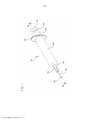
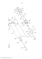
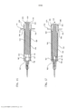
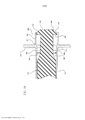
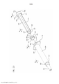
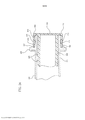
[021] A Figura 1 ilustra uma vista em perspectiva de um conjunto de seringa de acordo com uma modalidade da invenção mostrada; A Figura 2 ilustra uma vista em perspectiva desmontada do conjunto de seringa mostrado na Figura 1; A Figura 3 mostra uma visão em seção transversal do cilindro mostrado na Figura 2 tomada ao longo da linha 3-3; A Figura 4 é uma visão ampliada de uma porção do cilindro mostrado na figura. 3; A Figura 5 é uma visão em seção transversal do tampão mostrado na Figura 2 tomada ao longo da linha 5-5; A Figura 6 é uma visão em seção transversal da haste de êmbolo mostrada na Figura 2 tomada ao longo da linha 6-6; A Figura 7 é uma visão em seção transversal tomada ao longo da linha 7-7 da Figura 1; A Figura 8 é uma ilustração da Figura 7 mostrando a haste de êmbolo sendo movida na direção proximal; A Figura 9 é uma ilustração da Figura 8 mostrando a haste de êmbolo sendo movida na direção distal; A Figura 10 é uma ilustração da Figura 9 mostrando a haste de êmbolo na travada fechada no cilindro da seringa; A Figura 11 é uma visão ampliada da porção proximal do conjunto mostrado na Figura 10; A Figura 12 ilustra uma visão em perspectiva da Figura 10; A Figura 13 é uma ilustração da Figura 7 mostrando a haste de êmbolo sendo movida na direção proximal e do tampão desengatado da haste de êmbolo; A Figura 14 ilustra uma vista em perspectiva de uma modalidade de um con junto de seringa com indicadores ou marcadores visuais dispostos no cilindro e a porção de engate do tampão da haste de êmbolo; A Figura 15 ilustra uma visão em perspectiva desmontada do conjunto mostrado na Figura 14; A Figura 16 é uma visão em seção transversal tomada ao longo da linha 1616; A Figura 17 é uma ilustração da Figura 16 mostrando a haste de êmbolo na posição travada no cilindro da seringa; A Figura 18 é uma visão ampliada da porção proximal do conjunto mostrado na Figura 17; A Figura 19 é vista em perspectiva de um conjunto de seringa de acordo com a modalidade alternativa da invenção; A Figura 20 é uma visão em perspectiva desmontada do conjunto de seringa mostrado na Figura 19; A Figura 21 é uma visão em seção transversal ampliada tomada ao longo da linha 21-21 da extremidade proximal da haste de êmbolo mostrada na Figura 20; A Figura 22 é uma visão em seção transversal ampliada tomada ao longo da linha 22-22 da extremidade proximal do cilindro de seringa mostrado na Figura 20; A Figura 23 é uma ilustração da Figura 19 mostrando a válvula de pressão travada ao cilindro da seringa; e A Figura 24 é uma visão em seção transversal ampliada tomada ao longo da linha 24-24 da extremidade proximal do conjunto de seringa mostrado na Figura 23.[021] Figure 1 illustrates a perspective view of a syringe assembly according to an embodiment of the invention shown; Figure 2 illustrates an exploded perspective view of the syringe assembly shown in Figure 1; Figure 3 shows a cross-sectional view of the cylinder shown in Figure 2 taken along line 3-3; Figure 4 is an enlarged view of a portion of the cylinder shown in the figure. 3; Figure 5 is a cross-sectional view of the plug shown in Figure 2 taken along line 5-5; Figure 6 is a cross-sectional view of the piston rod shown in Figure 2 taken along line 6-6; Figure 7 is a cross-sectional view taken along line 7-7 of Figure 1; Figure 8 is an illustration of Figure 7 showing the plunger rod being moved in the proximal direction; Figure 9 is an illustration of Figure 8 showing the plunger rod being moved in the distal direction; Figure 10 is an illustration of Figure 9 showing the plunger rod in the latch closed on the syringe barrel; Figure 11 is an enlarged view of the proximal portion of the assembly shown in Figure 10; Figure 12 illustrates a perspective view of Figure 10; Figure 13 is an illustration of Figure 7 showing the plunger rod being moved in the proximal direction and the cap disengaged from the plunger rod; Figure 14 illustrates a perspective view of one embodiment of a syringe assembly with visual indicators or markers disposed on the barrel and the piston rod cap engaging portion; Figure 15 illustrates an exploded perspective view of the assembly shown in Figure 14; Figure 16 is a cross-sectional view taken along line 1616; Figure 17 is an illustration of Figure 16 showing the plunger rod in the locked position in the syringe barrel; Figure 18 is an enlarged view of the proximal portion of the assembly shown in Figure 17; Figure 19 is a perspective view of a syringe assembly in accordance with the alternative embodiment of the invention; Figure 20 is an exploded perspective view of the syringe assembly shown in Figure 19; Figure 21 is an enlarged cross-sectional view taken along line 21-21 of the proximal end of the plunger rod shown in Figure 20; Figure 22 is an enlarged cross-sectional view taken along line 22-22 of the proximal end of the syringe barrel shown in Figure 20; Figure 23 is an illustration of Figure 19 showing the pressure valve locked to the syringe barrel; and Figure 24 is an enlarged cross-sectional view taken along line 24-24 of the proximal end of the syringe assembly shown in Figure 23.
[022] Antes de descrever várias modalidades exemplares da invenção, deve ser entendido que a invenção não se limita aos detalhes de construção ou etapas de processo estabelecidos na descrição que se segue. A invenção é capaz de outras modalidades e de ser praticada ou a ser executada de várias maneiras.[022] Before describing various exemplary embodiments of the invention, it should be understood that the invention is not limited to the construction details or process steps set forth in the description that follows. The invention is capable of other modalities and of being practiced or being carried out in various ways.
[023] Um aspecto da presente invenção prevê um conjunto de seringa, incluindo um cilindro, haste de êmbolo e tampão com características individuais e de construção que permitem ao usuário passivamente travar a haste de êmbolo dentro do cilindro para evitar a reutilização do conjunto de seringa.[023] One aspect of the present invention provides for a syringe assembly including a cylinder, plunger rod and cap with individual and constructional features that allow the user to passively lock the plunger rod into the cylinder to prevent reuse of the syringe assembly .
[024] A Figura 1 mostra um conjunto de seringa 100 de acordo com uma ou mais modalidades. Como mostrado na Figura 2, o conjunto de seringa inclui um cilindro 120, uma haste de êmbolo 140 e um tampão 160, dispostos de tal forma que a extremidade proximal 169 do tampão é acoplada à extremidade distal 141 da haste de êmbolo. O tampão conectado 160 e haste de êmbolo 140 são inseridos na extremidade proximal 129 do cilindro 120.[024] Figure 1 shows a
[025] Como melhor mostrado na Figura 3, o cilindro 120 tem uma parede lateral cilíndrica 110 com uma superfície interna 126 que define uma câmara 128. Em uma modalidade, a câmara 128 mantém o conteúdo do conjunto de seringa que pode incluir medicamentos na forma de pó ou líquida. O cilindro 120 é mostrado como tendo uma extremidade aberta proximal 129, uma extremidade distal 121, e uma parede distal 122. A parede distal 122 tem uma abertura 111 em comunicação fluida com a câmara 128.[025] As best shown in Figure 3,
[026] A parede lateral 110 do cilindro 120 define uma câmara com um diâmetro interno contínuo ao longo do eixo longitudinal da seringa. Alternativamente, o cilindro pode incluir uma parede lateral que tem um diâmetro interno, o qual diminui de forma linear a partir da extremidade proximal para a extremidade distal. Deve ser entendido que a configuração apresentada é meramente exemplar, e que os componentes podem ser diferentes em forma e tamanho do que é mostrado. Por exemplo, o cilindro pode ter uma forma de prisma externamente, mantendo uma forma cilíndrica internamente. Alternativamente, as superfícies externa e interna do cilindro podem ter não formas em seção transversal não circulares.[026] The
[027] A seringa 120 é mostrada como tendo um flange periférico 124 acoplado na extremidade proximal 129 do cilindro de 120. O cilindro 120 inclui ainda uma cânula de agulha 150, tendo um lúmen 153 acoplado à abertura 111 na parede distal 122 do cilindro 120. Como é conhecido na técnica, o meio de acoplamento 152 é provido para a fixação da cânula de agulha 150 à parede distal 122. O conjunto 100 também pode incluir mais de uma capa protetora sobre a cânula de agulha (não mostrados).The
[028] Referindo-se à Figura 3, a extremidade proximal do cilindro 129 inclui uma extensão anular ou colar 400. A extensão anular 400 inclui uma extremidade proximal 409 e uma extremidade distal 401. Como será mais completamente descrito aqui, a extensão anular 400 pode ter um diâmetro maior do que o diâmetro da válvula de pressão 300 e, em uma ou mais modalidades, a extensão anular 400 também pode ter um comprimento que lhe permitiria envolver ou cobrir a válvula de pressão 300 após um ciclo completo de injeção.[028] Referring to Figure 3, the proximal end of
[029] Como mostrado mais claramente na Figura 3, o cilindro 120 inclui ainda uma nervura 123 adjacente à sua extremidade proximal 129. A nervura 123 é distalmente adjacente à extensão anular 400. Em uma ou mais modalidades, a nervura 123 pode ser formada na parede interna da extensão anular (não mostrado) e, em tais modalidades, fornece um meio para travar a haste de êmbolo disposta na haste de êmbolo tal que avança distalmente além da nervura 123 quando o tampão 160 está em contato com a parede distal 122 da seringa. Em uma modalidade específica, uma pluralidade de nervuras é disposta na superfície interna 126 do cilindro. Em uma modalidade mais específica, uma nervura é distalmente adjacente à extensão anular e uma segunda nervura é formada na parede interna da extensão anular. O diâmetro interno do cilindro no local da nervura 123 é menor do que o diâmetro interno do cilindro 120 em outras localidades ao longo do comprimento do cilindro. Em vez de uma nervura contínua 123, um ou mais separadores opcionais ou detentores podem ser usados para criar uma região do cilindro com um diâmetro menor do que o diâmetro interno do cilindro 120. Desta forma, a haste de êmbolo pode ser mantida no cilindro por tais separadores tal que são co-radiais com separadores ou detentores na haste de êmbolo. Em uma modalidade específica, a nervura pode incluir um anel formado ao longo de toda a circunferência da superfície interna 126 ou uma porção da superfície interna 126 o diâmetro interno do cilindro 120 (não mostrados). Em uma ou mais modalidades, o cilindro 120 também pode incluir uma região de transição de diâmetro proximalmente adjacente à nervura 123 (não mostrada). Em tal configuração, o diâmetro interno do cilindro na região de transição de diâmetro aumenta da extremidade distal 121 para a extremidade proximal 129 do cilindro 120. O cilindro pode incluir também uma região de diâmetro aumentado proximalmente adjacente à região de transição de diâmetro (não mostrados). Em tal configuração, a região de diâmetro aumentado tem um diâmetro interno maior do que o diâmetro interno do cilindro de toda a região de transição de diâmetro.[029] As shown more clearly in Figure 3,
[030] O cilindro pode ser feito de plástico, vidro ou outro material adequado. O cilindro inclui ainda indícios de medição de dosagem opcional (não mostrados).[030] The cylinder can be made of plastic, glass or other suitable material. The cylinder also includes optional metering indicia (not shown).
[031] Referindo-se agora à Figura 5, o tampão 160 mostrado tem uma extremidade distal 161, uma extremidade proximal 169, um corpo de tampão 164 e uma borda periférica 162 que forma um selo com a superfície interna 126 do cilindro. Em uma ou mais modalidades, a borda periférica 162 do tampão 160 tem um diâmetro maior do que o diâmetro da superfície interna da nervura 123. O tampão 160 mostrado na Figura 5 inclui uma ponta alongada opcional 166 em sua extremidade distal 161 para facilitar a redução do fluido residual e expulsão de fluido do cilindro da seringa.[031] Referring now to Figure 5, the
[032] O tampão 160 é mostrado como tendo adicionalmente uma porção cilíndrica 165 adjacente ao corpo do tampão 164 na sua extremidade proximal 169. Um pescoço 163 é adjacente à porção cônica 165 na extremidade proximal 169 do tampão 160. O corpo do tampão 164 é mostrado como também incluindo um recesso interno 168, que permite que o tampão 160 se conecte à haste de êmbolo.[032] The
[033] O tampão é normalmente feito de plástico ou outro material facilmente descartável e/ou reciclável. Pode ser desejável incorporar borracha natural ou sintética no tampão ou utilizar um selo de borracha natural ou sintética com o tampão. Será entendido que o tampão pode incorporar vários selos.[033] The tampon is usually made of plastic or other easily disposable and/or recyclable material. It may be desirable to incorporate natural or synthetic rubber in the plug or to use a natural or synthetic rubber seal with the plug. It will be understood that the tampon can incorporate multiple seals.
[034] Referindo-se agora à Figura 6, o conjunto de seringa inclui uma haste de êmbolo 140 com uma extremidade proximal 149, uma extremidade distal 141, e um corpo principal que se estende entre a extremidade proximal 149 e a extremida- de distal 141. A extremidade distal 141 da haste de êmbolo inclui uma porção de engate do tampão 146, que conecta o tampão 160 à haste de êmbolo 140. Uma aba periférica 147 pode ser fornecida para ajudar a manter o tampão 160 sobre o êmbolo 140. Tal como acontece com a nervura do cilindro, detentores ou separadores podem ser usados para manter o tampão 160 sobre a haste de êmbolo 140. A porção de engate do tampão 146 também pode incluir um ou mais entalhes 142 na extremidade distal 141 da haste de êmbolo.[034] Referring now to Figure 6, the syringe assembly includes a
[035] A haste de êmbolo 140 inclui ainda uma válvula de pressão 300 na extremidade proximal 149 da haste de êmbolo 140. Na modalidade mostrada, a válvula de pressão 300 inclui ainda uma extremidade distal 301, uma extremidade proximal 309 e uma porção de contorno 310 entre a extremidade distal e a extremidade proximal. A porção de contorno 310 inclui um segmento da válvula de pressão com um diâmetro que diminui a partir da extremidade distal 301 para a extremidade proximal 309 da válvula de pressão. Em um ou mais modalidades, a extremidade proximal da válvula de pressão 309 pode ter uma superfície plana ou pode ser curvada. Em uma modalidade específica, a válvula de pressão pode ser contornada para caber dentro do cilindro após um ciclo completo de injeção. Em uma modalidade mais específica, a válvula de pressão pode ser contornada para pelo menos parcialmente se embutir ou se encaixar dentro da extensão anular disposta na extremidade proximal do cilindro. Em uma modalidade ainda mais específica, a válvula de pressão pode inclui um rótulo e / ou superfície gravável.[035] The
[036] Ainda referindo-se à Figura 6, a haste de êmbolo 140 inclui ainda uma protrusão 144 mostrada como uma protrusão 144 entre a válvula de pressão 300 e o corpo principal 148. O diâmetro externo da haste de êmbolo na protrusão 144 é maior do que o diâmetro interno do cilindro 120 na nervura 123. Em uma modalidade específica da invenção, a protrusão 144 inclui uma porção cônica que facilita o movimento distal da protrusão além da nervura 123 e para dentro do cilindro 120, como se verá na discussão subseqüente de funcionamento da seringa. Em pelo menos uma modalidade, o conjunto de seringa é configurado para permitir que a protrusão 144 avance distalmente além da nervura 123, para travar a haste de êmbolo no cilindro, quando o usuário assentar a haste de o êmbolo no cilindro (como mais claramente demonstrado nas Figuras 10 e 11). A haste de êmbolo 140 também pode incluir um disco de 145 disposto na extremidade distal 141 da haste de êmbolo. Em uma modalidade, o disco 145 é o meio de travamento do êmbolo dentro do cilindro.[036] Still referring to Figure 6, the
[037] Na modalidade mostrada, o tampão 160 pode se mover distal e proximalmente dentro do cilindro, quando conectado à porção de engate do tampão 146 da haste de êmbolo 140. Como será entendido com a descrição do funcionamento do conjunto de seringa e com referência à Figura 7, o tampão é capaz de se mover distal e proximalmente uma distância axial pré-selecionada 132 em relação à porção de engate do tampão. Em uma configuração alternativa, o tampão e a haste de êmbolo podem ser conectados em uma relação fixa, em que o tampão é impedido de se mover distal e proximalmente em relação à porção de engate do tampão ou haste de êmbolo.[037] In the embodiment shown, the
[038] A haste de êmbolo pode ser feita de plástico ou outro material adequado. A protrusão pode também ser composta de plástico ou um material mais rígido adequado para travar a haste de êmbolo dentro do cilindro. Da mesma forma, a válvula de pressão pode ser feita de plástico ou outro material adequado. Em uma modalidade específica, a válvula de pressão é feita de um material que cria uma superfície escorregadia, o que exige que o usuário seja capaz de captar uma maior área de superfície para remover a haste de êmbolo ou aplicar uma força à haste de êmbolo na direção proximal.[038] The piston rod can be made of plastic or other suitable material. The protrusion can also be composed of plastic or a more rigid material suitable for locking the piston rod into the cylinder. Likewise, the pressure valve can be made of plastic or other suitable material. In a specific embodiment, the pressure valve is made of a material that creates a slippery surface, which requires the user to be able to capture a larger surface area to remove the piston rod or apply force to the piston rod at the proximal direction.
[039] Na Figura 7, o cilindro 120 mantém o tampão 160 e a haste de êmbolo 140 na câmara, em que o tampão assentado, "disposto", ou está em contato com a parede distal 122 do cilindro 120. A borda periférica do tampão 162 forma um selo com a superfície interna 126 do cilindro 120. Em uma modalidade, o tampão 160 é conectado à porção de engate do tampão 146 da haste de êmbolo 140. A porção de engate do êmbolo 146 é removivelmente mantida no recesso 168 do corpo do tampão 164 pelo pescoço 163.[039] In Figure 7,
[040] Na configuração alternativa em que o tampão e a haste de êmbolo são conectados em uma relação fixa, o tampão não está disposto e é posicionado dentro do cilindro a uma distância entre a parede distal o tampão. Nesta configuração, quando o tampão é movido distalmente e está em contato com a parede distal, a válvula de pressão pode se deslocar dentro do cilindro ou extensão anular. Em tal modalidade específica, o conjunto de seringa é pré-carregado com medicamentos, com tampão posicionado na extremidade proximal do cilindro.[040] In the alternative configuration where the cap and the piston rod are connected in a fixed relationship, the cap is not disposed and is positioned inside the cylinder at a distance between the distal wall and the cap. In this configuration, when the plug is moved distally and is in contact with the distal wall, the pressure valve can travel within the cylinder or annular extension. In such a specific embodiment, the syringe assembly is pre-loaded with medication, with a plug positioned at the proximal end of the barrel.
[041] Referindo-se à Figura 7, um espaço entre o tampão 160 e a extremidade distal do corpo principal 148, antes do início do ciclo de injeção, define a distância axial pré-selecionada 132. A válvula de pressão permanece fora do cilindro 120 e extensão anular 400 porque o comprimento total da haste de êmbolo 140 e tampão, juntamente com a distância axial pré-selecionada 132, é maior do que o comprimento do cilindro 120 da parede distal 122 até a extremidade proximal da extensão anular 409. Na modalidade mostrada na Figura 7, a protusão 144 também permanece no lado proximal da nervura de 123 por este motivo.[041] Referring to Figure 7, a space between the
[042] A distância entre a protusão 144 e a borda periférica 162 do tampão 160 define uma primeira distância, D1. Nas configurações que não incluem uma pro- trusão 144, D1 pode ser a distância da borda periférica do tampão 160 para a extremidade proximal 309 da válvula de pressão ou qualquer outro ponto fixo sobre a haste de êmbolo.[042] The distance between the
[043] A Figura 8 ilustra o conjunto de seringa em uso e, especificamente, mostra uma etapa de aspiração ou preenchimento, de acordo com uma ou mais modalidades da presente invenção. Quando o usuário aplica uma força à haste de êmbolo 140 na direção proximal indicada pela seta na Figura 8, a haste de êmbolo 140 e o tampão 160 se movem em conjunto na direção proximal, enquanto a porção de acoplamento do tampão 146 é conectada ao tampão 160 pela aba 147. Em uma ou mais modalidades, o espaço que define a distância axial pré-selecionada 132 é mantido enquanto o tampão 160 e a haste de êmbolo 140 se movem juntos na direção proximal ao longo da superfície interna do cilindro da seringa. O usuário termina a aplicação de força proximal à haste de êmbolo 140 uma vez que a quantidade desejada de medicamento é colocada dentro da seringa. Durante a etapa de aspiração, a haste de êmbolo e o corpo do tampão se movem na direção proximal em conjunto para colocar a medicação dentro da seringa, mantendo a primeira distância D1.[043] Figure 8 illustrates the syringe assembly in use and specifically shows an aspiration or filling step, according to one or more embodiments of the present invention. When the user applies force to the
[044] A Figura 9 também mostra o conjunto de seringa em uso e, especificamente, demonstra a aplicação de força distal à haste de êmbolo durante a injeção. Em uma modalidade, quando o usuário aplica uma força na direção distal à haste de êmbolo 140 como indicado pela seta, a haste de êmbolo 140 move-se em uma direção distal pelo comprimento do espaço que define a distância axial pré-selecionada 132 na Figura 7, enquanto o tampão 160 permanece estacionário. O tampão 160 permanece estacionário porque a força de atrito criada pela borda periférica 162 do tampão na superfície interna 126 do cilindro é maior do que a força de atrito criada pela porção de engate do tampão 146 entrando no recesso 168 do tampão 160. Consistente com pelo menos uma modalidade, uma vez que a porção de engate do tampão tiver distalmente se movido o comprimento da distância axial pré- selecionada 132 e está em contato com a extremidade proximal do recesso 168, o tampão 160 e a haste de êmbolo 140 começam a se mover em conjunto na direção distal. Além disso, a força aplicada pelo usuário é maior do que o atrito entre a borda periférica 162 do tampão 160 e a superfície interna 126 do cilindro e, portanto, o tampão 160 é forçado a se mover na direção distal com a haste de êmbolo 140. Em uma modalidade, o usuário pode injetar uma quantidade limitada de fluido aspirado ou exercer uma força limitada sobre a haste de êmbolo na direção distal para liberar ou expulsar algum do fluido aspirado, sem bloquear a haste de êmbolo, desde que o conjunto de seringa não seja assentado. No entanto, como será descrito mais adiante com relação à Figura 10, um usuário pode assentar o tampão contra a parede distal do cilindro da seringa, travando a haste de êmbolo no cilindro.[044] Figure 9 also shows the syringe assembly in use and specifically demonstrates the application of force distal to the plunger rod during injection. In one embodiment, when the user applies a force in the distal direction to the
[045] Ao expelir o conteúdo da seringa, a haste de êmbolo se move em uma direção distal o comprimento da distância axial pré-selecionada 132 mostrada na Figura 7, enquanto o tampão permanece estacionário, conseqüentemente, fechando o espaço que define a distância axial pré-selecionada 132. Depois que o conteúdo da seringa foi totalmente expulso, a distância entre a protusão 144 e a borda periférica 162 define uma segunda distância, D2, em que D2 é a diferença entre a primeira distância, D1, e o espaço que define uma distância axial pré-selecionada 132.[045] When expelling the contents of the syringe, the plunger rod moves in a distal direction the length of the preselected
[046] A Figura 10 ilustra uma modalidade do conjunto de seringa após a haste de êmbolo ter sido travada dentro do cilindro. Em um ou mais modalidades, a entrada da porção de engate do tampão no recesso 168 do tampão 160 (como mostrado na Figura 9) fecha o espaço que define a distância axial pré-selecionada 132, permitindo que a protrusão 144 avance além da nervura de travamento 123 (como mais claramente mostrado na figura. 11). A protrusão 144 tem um diâmetro externo maior do que o diâmetro interno do cilindro na nervura 123. Assim, em uma ou mais modalidades, a nervura 123 trava a protrusão 144 dentro do cilindro 120, e impede o movimento proximal da haste de êmbolo 140. Na modalidade mostrada, a válvula de pressão 300 também pode avançar distalmente na extensão anular 400. Como mais claramente mostrado na Figura 11, a válvula de pressão 300 distalmente avança na extensão anular 400 tal que a extensão anular cobre uma porção da válvula de pressão 300, deixando o resto da válvula de pressão se estendendo além da protru-são. Em tais modalidades, a válvula de pressão pode ser difícil de agarrar pelo uso da porção de contorno opcional 310.[046] Figure 10 illustrates an embodiment of the syringe assembly after the piston rod has been locked inside the cylinder. In one or more embodiments, the entry of the plug engaging portion into the
[047] Em modalidades em que o tampão é conectado em uma relação fixa com a haste de êmbolo, após o conteúdo da seringa ter sido totalmente expulso, o espaço entre o tampão e a parede distal é fechado, permitindo, assim, que a válvula de pressão se mova dentro do cilindro ou extensão anular e, sempre que uma nervura e / ou protrusão é utilizada, permite que a protrusão avance distalmente além da nervura.[047] In modalities where the cap is connected in a fixed relationship with the plunger rod, after the contents of the syringe have been fully expelled, the space between the cap and the distal wall is closed, thus allowing the valve of pressure moves within the cylinder or annular extension and, whenever a rib and/or protrusion is used, allows the protrusion to advance distally beyond the rib.
[048] De acordo com a modalidade da Figura 12, a extensão anular 400 pode cobrir todo o comprimento da válvula de pressão 300, proibindo o acesso à válvula de pressão. Em modalidades que não utilizam uma extensão anelar, a válvula de pressão 300 está configurada para embutir dentro do cilindro 120.[048] According to the embodiment of Figure 12, the
[049] A Figura 13 mostra o conjunto de seringa em uma configuração em que o tampão 160 separou da porção de engate do tampão 146. De acordo com uma ou mais modalidades da invenção, o tampão 160 e porção de engate do tampão 146 desengatam para impedir que um usuário desmonte as peças do conjunto de seringa antes da utilização. Como descrito de outra forma em referência à Figura 5, a borda periférica 162 do tampão 160 tem um diâmetro maior do que o diâmetro da superfície interna da nervura 123. Consistente com pelo menos uma modalidade da invenção, quando um usuário aplica uma força à haste de êmbolo 140 na direção proximal, a nervura 123 bloqueia a borda periférica 162 do tampão 160 e a aba 147 da porção de engate do tampão 146 desconecta do pescoço 163 do tampão. A nervura 123 exerce uma força maior na borda periférica do tampão do que a força ou atrito exercida pela aba da porção de engate do tampão da haste de êmbolo e a porção do pescoço do tampão, enquanto força proximal é aplicada à haste de êmbolo.[049] Figure 13 shows the syringe assembly in a configuration where the
[050] Em modalidades do conjunto de seringa que não incluem uma nervura 123, o tampão se separa da porção de engate do tampão quando um usuário tenta puxar a haste de êmbolo para fora do cilindro. Em modalidades específicas, a rápida retirada da haste de êmbolo cria um vácuo entre a parede distal do cilindro e o tampão e permite que o tampão se separe da porção de engate do tampão. Em modalidades mais específicas, o atrito entre a borda periférica do tampão 162 e a superfície interna do cilindro 126 é maior do que a força ou para conectar a porção de engate do tampão 146 e o tampão 160.[050] In syringe assembly embodiments that do not include a
[051] A Figura 14 mostra um conjunto de seringa 120 em que o cilindro inclui um marcador visual 500. O marcador é alinhado à nervura 123, como mais claramente mostrado na Figura 15. O marcador pode ser integralmente formado na parede lateral do cilindro ou pode ser adicionado à superfície externa da parede lateral. O marcador pode ser impresso com tinta, adesivamente aplicado, uma superfície texturizada ou um pedaço separado que é fixado ao redor do cilindro da seringa. O marcador pode formar um anel em torno da circunferência da parede lateral, ou ter a forma de separadores dispostos a intervalos regulares em toda a circunferência da parede lateral. Em uma modalidade específica, o marcador é uma faixa colorida. Em uma modalidade mais específica, o marcador pode incluir texto na forma de uma ou mais letras e / ou números, formas geométricas, símbolos ou combinações dos mesmos, para informar aos usuários que a seringa está inutilizada.[051] Figure 14 shows a
[052] A Figura 15 também mostra uma haste de êmbolo 140 com um indicador visual ou display 510 disposto na porção de engate do tampão 146. Tal como acontece com o marcador visual 500, o indicador visual 510 pode ser integralmente formado com a porção de engate do tampão da haste de êmbolo ou ser adicionado à superfície externa da mesma. O indicador ou display pode ser impresso com tinta, adesivamente aplicado, uma superfície texturizada ou um pedaço separado que é fixado à porção de engate do tampão. Em um ou mais modalidades, o indicador ou display pode incluir um padrão, uma porção sólida e / ou pode cobrir toda a superfície da porção de engate do tampão. Em uma modalidade específica, o indicador é uma faixa colorida disposta ao longo do comprimento da porção de engate do tampão 146 entre a extremidade distal 141 e o corpo principal 148 da haste de êmbolo. Em uma modalidade mais específica, o indicador é uma faixa colorida disposta ao longo da circunferência da porção de engate do tampão 146 da haste de êmbolo. Em uma modalidade ainda mais específica, o marcador pode incluir texto na forma de uma ou mais letras e / ou números, formas geométricas, símbolos ou combinações dos mesmos.[052] Figure 15 also shows a
[053] Como mais claramente mostrado na Figura 16, um espaço entre o tampão 160 e a extremidade distal do corpo principal 148 define a distância axial pré- selecionada 132 antes do ciclo de injeção. O indicador visual 510 é visível quando o espaço está presente. O marcador visual 500 é disposto na superfície externa do cilindro 120 e alinhado com a nervura 123. Conforme descrito em referência à Figura 8, quando o usuário aplica uma força à haste de êmbolo 140 na direção proximal indicada pela seta na Figura 8, a haste de êmbolo 140 e o tampão 160 se movem em conjunto na direção proximal, enquanto a rolha porção de engate do tampão 146 é conectada ao tampão 160 pela aba 147. Em uma ou mais modalidades, o espaço que define a distância axial pré-selecionada 132 é mantida enquanto o tampão 160 e a haste de êmbolo 140 se movem juntos na direção proximal ao longo da superfície interna do cilindro da seringa. Assim, o indicador visual de 510 continua a ser visível.[053] As more clearly shown in Figure 16, a space between the
[054] Tal como descrito com referência à Figura 9, quando expelindo o conteúdo da seringa, a haste de êmbolo se move em uma direção distal o comprimento da distância axial pré-selecionada 132 mostrada nas Figuras 7 e 14, enquanto o corpo do tampão permanece estacionário, conseqüentemente fechando o espaço que define a distância axial pré-selecionada 132. O movimento da porção de engate do tampão, na direção distal em relação ao tampão, permite que a porção de engate do tampão 146 da haste de êmbolo se mova para o recesso 168 do tampão (como mostrado na Figura 9). Como pode ser visto mais claramente na Figura 15, este movimento relativo permite que o corpo do tampão 164 cubra a porção de engate do tampão 146 e bloqueie a visibilidade do indicador visual 510.[054] As described with reference to Figure 9, when expelling the contents of the syringe, the plunger rod moves in a distal direction the length of the preselected
[055] Como mais claramente mostrado nas Figuras 17 e 18, o marcador visual 500 disposto no cilindro 120 e alinhado com a nervura 123 também pode fornecer comunicação visual de que o conjunto de seringa está inutilizado e o avanço da protrusão 144 além a nervura 123. Em um ou mais modalidades, quando porção de engate do tampão entra no recesso 168 do tampão 160 (como mostrado na Figura 9), o espaço que define a distância axial pré-selecionada 132 é fechado e a protusão 144 pode avançar além da nervura 123 e / ou a válvula de pressão 300 pode mover- se distalmente para dentro da extensão anular 400 (como mostrado mais claramente nas Figuras 10 e 11). Em tais modalidades, a localização da protrusão 144 em relação ao marcador visual 500 indica se a haste de êmbolo foi travada dentro do cilindro e se o conjunto de seringa foi inutilizado. Antes de a haste de êmbolo ser travada, a protrusão 144 é proximalmente adjacente ao marcador visual 500. Uma vez que a haste de êmbolo é travada, a protrusão 144 fica distalmente adjacente ao marcador visual 500.[055] As more clearly shown in Figures 17 and 18,
[056] O marcador visual 500 também pode ser usado em modalidades do conjunto de seringa que não incluem uma nervura ou uma protusão. Em tais modali-dades, o marcador visual pode estar em outros locais ao longo do comprimento do cilindro para visualmente notificar o usuário de que a seringa está inutilizada. Por exemplo, o marcador visual pode ser disposto perto da extremidade proximal do ci-lindro ou sobre a extensão anular de modo que seja alinhado distalmente adjacente a um ponto correspondente na haste de êmbolo. Em utilização, uma vez que a ex-tremidade distal do tampão está em contato com a parede distal do cilindro, o mar-cador visual se move em um local distalmente adjacente ao ponto correspondente sobre a haste de êmbolo para uma proximal adjacente ao ponto correspondente na haste de êmbolo. O ponto correspondente pode incluir um marcador visual corres-pondente adicionado ao êmbolo ou um recurso existente de uma haste de êmbolo, tal como uma porção cônica da haste de êmbolo 148 ou a porção de contorno da válvula de pressão 310.[056]
[057] Será apreciado que cada um de marcador visual 500 e indicador visual 510 pode ser usado sozinho ou em combinação.[057] It will be appreciated that each of
[058] As Figuras 19 a 24 mostram uma modalidade do conjunto de seringa com um meio alternativo para impedir a remoção da haste de êmbolo do cilindro depois que o conjunto de seringa foi utilizado. Na modalidade mostrada na Figura 20, o conjunto inclui um cilindro 220, uma haste de êmbolo 240 e um tampão 260 dispostos de modo que a extremidade proximal do tampão 269 é conectado à extremidade distal da haste de êmbolo 241. O tampão 260 seguido da haste de êmbolo 240 é inserido na extremidade proximal do cilindro de 229. Um flange 224 é conectado à extremidade proximal 229 do cilindro 220. O cilindro 220 inclui ainda um cubo de acoplamento 252 na abertura na parede distal 222 do cilindro 220. Uma ou mais modalidades do cilindro de acoplamento 252 acopla uma cânula de agulha 250 (não mostrada) à parede distal 222. O conjunto também pode incluir uma capa protetora sobre cânula de agulha (não mostradas) ou um sistema de retração da agulha (não mostrado).[058] Figures 19 to 24 show an embodiment of the syringe assembly with an alternative means to prevent removal of the plunger rod from the cylinder after the syringe assembly has been used. In the embodiment shown in Figure 20, the assembly includes a
[059] Como mais claramente mostrado na Figura 22, o cilindro pode ainda in- cluir uma nervura de travamento 223, nervura de travamento ou de outros meios para impedir a remoção da haste de êmbolo do cilindro, tendo uma superfície interna com um diâmetro menor do que o diâmetro da superfície interno do cilindro. Regiões de transição de diâmetro opcionais 225 também podem ser incluídas para facilitar a ativação dos meios para impedir a remoção da haste de êmbolo do cilindro. Um colar 600 tendo uma extremidade distal 601 e uma extremidade proximal 609 está acoplado à extremidade proximal 229 do cilindro e inclui um membro anular 610 tendo uma endentação 611 e um sulco 613 definido pelo perímetro 227.[059] As more clearly shown in Figure 22, the cylinder may further include a locking
[060] Referindo-se agora às Figuras 20 e 21, a haste de êmbolo 240 é mostrado como tendo um corpo principal 248, uma extremidade distal 241 e uma extremidade proximal 249. A haste de êmbolo 240 inclui ainda uma capa de válvula de pressão 700 na sua extremidade proximal 249 e porção de engate do tampão 246 na sua extremidade distal 241 para conectar o tampão 260 para a haste de êmbolo 240. Como mostrado mais claramente na Figura 20, a porção de engate do tampão 246 também inclui um recesso de êmbolo (não mostrado) e um retentor 247. Pelo menos uma modalidade da invenção inclui um acoplamento press-fit ou outros meios adequados para prender a extremidade do tampão. A capa de válvula de pressão 700 mostrada nas Figuras 21 a 23 inclui uma extremidade distal 701, extremidade proximal 709, incluindo uma parede de extremidade 712 e uma parede lateral 710 entre a extremidade distal e a extremidade proximal 709 definindo uma cavidade 713 com o corpo principal 248 do êmbolo. A parede lateral 710 inclui ainda uma projeção 711.[060] Referring now to Figures 20 and 21, the
[061] O tampão 260 mostrado na Figura 20 inclui uma extremidade distal 261 tendo uma borda periférica 262, uma extremidade proximal 269 e uma borda periférica 262 que forma um selo com a parede interno do cilindro 220. Em modalidades que utilizam uma nervura de travamento 223, borda periférica 262 do tampão 260 pode ter um diâmetro maior do que o diâmetro da superfície interno do cilindro no local da nervura 223 e, assim, fornecer um meio para separação do tampão da porção de engate do tampão. O tampão 260 pode ainda incluir um corpo de tampão 264 tendo uma borda periférica 263 em sua extremidade proximal 269 que forma um recesso (não mostrado). A borda periférica 262 do tampão 260 forma um selo com a superfície interno do cilindro 220. O retentor 247 da porção de engate do tampão 246 mantém a borda periférica 263 do tampão 260 para conectar o tampão 260 à haste de êmbolo 240.[061] The
[062] Como acontece com os conjuntos de seringa mostrados nas Figuras 7 a 10, um espaço entre o tampão 260 a extremidade distal do corpo principal 248 define uma distância axial pré-selecionada (não mostrada). A distância entre a borda periférica 262 e a parede de extremidade 712 da capa da válvula de pressão 700 define um primeiro comprimento L1 (não mostrado). Conforme descrito com referência às Figuras 7 a 10, como a distância axial pré-selecionada é reduzida pelo movimento relativo entre o tampão 260 e porção de engate do tampão 246 durante a aspiração e ciclos de injeção do conjunto de seringa, a distância entre a borda periférica 262 do tampão 260 e a capa da válvula de pressão 700 é reduzida para um se-gundo comprimento L2 (não mostrado). Em uma modalidade, o usuário pode injetar uma quantidade limitada do fluido aspirado ou exercer uma força limitada sobre a haste de êmbolo no sentido distal para liberar ou expulsar algum do fluido aspirado, sem bloquear a haste de êmbolo, desde que o conjunto de seringa não seja assentado. No entanto, como será descrito mais abaixo, um usuário normalmente irá expulsar substancialmente todo o conteúdo da seringa por assentamento do tampão na parede distal do cilindro.[062] As with the syringe assemblies shown in Figures 7 through 10, a space between the
[063] As Figuras 23 a 24, que ilustram o conjunto de seringa após o comprimento reduzido L2, permite que a capa da válvula de pressão 700 avance distalmen- te no colar 600 em uma configuração embutida com o colar. O membro anular 610 do colar 600 se embute dentro da cavidade 713 da capa da válvula de pressão 700. A parede lateral 710 da tampa capa da válvula de pressão 700 se embute dentro do sulco 613 do colar 600. Como mais claramente mostrado na Figura 23, a projeção 711 e a endentação 611 se alinham para travar a capa da válvula de pressão 700 ao colar 600 na extremidade proximal do cilindro 229.[063] Figures 23 to 24, which illustrate the syringe assembly after the reduced length L2, allows the
[064] Será apreciado, como descrito anteriormente, que o tampão e haste de êmbolo podem ser conectados em uma relação fixa, de tal forma que o movimento distal do tampão e haste de êmbolo e permita que a válvula de pressão possa avançar distalmente no colar em uma configuração embutida com o colar.[064] It will be appreciated, as described above, that the cap and plunger rod can be connected in a fixed relationship such that the distal movement of the cap and plunger rod allows the pressure valve to advance distally into the collar in a built-in configuration with the collar.
[065] Em uma ou mais modalidades, a haste de êmbolo 240 pode incluir uma protusão, como descrito com referência às Figuras 1 a 18, que pode avançar distal- mente além da nervura de travamento 223 da modalidade mostrada na Figura 22 para impedir a remoção da haste de êmbolo do cilindro. A protrusão, conforme descrita com referência às Figuras 1 a 18, pode ser usada em conjunto com a capa de válvula de pressão 700 e o colar 600 das modalidades das Figuras 19 a 24. Também será entendido que a protrusão 144, extensão anular 400, válvula de pressão 300 com uma porção contornada 310 e a capa da válvula de pressão 700 e colar 600 podem ser usados sozinhos ou em várias combinações para impedir a remoção da haste de êmbolo ou reutilização do conjunto de seringa.[065] In one or more embodiments, the
[066] Modalidades do conjunto de seringa das Figuras 19 a 24 também podem incluir um marcador visual, indicador visual ou ambos, conforme descrito com referência às Figuras 14 a 18. Em uma modalidade específica, o cilindro pode incluir um marcador visual que indica que o conjunto de seringa foi inutilizado. Em uma modalidade mais específica, o cilindro 220 de uma ou mais modalidades também pode incluir um marcador visual alinhado com a nervura de travamento 223. Em uma modalidade mais específica, o conjunto de seringa pode incluir um indicador visual disposto na porção de engate do tampão 246.[066] Syringe assembly embodiments of Figures 19 to 24 may also include a visual marker, visual indicator, or both, as described with reference to Figures 14 to 18. In a specific embodiment, the barrel may include a visual marker indicating that the syringe set was unusable. In a more specific embodiment,
[067] De acordo com uma ou mais modalidades, o cilindro da seringa pode incluir a informações de identificação sobre o conjunto de seringa. Essas informações podem incluir, mas não estão limitadas a, uma ou mais informações de identificação sobre o conteúdo do conjunto de seringa ou informações sobre o destinatário pretendido.[067] According to one or more embodiments, the syringe barrel may include identifying information about the syringe assembly. Such information may include, but is not limited to, one or more identifying information about the contents of the syringe set or information about the intended recipient.
[068] A referência ao longo deste pedido a "uma modalidade", "determinadas modalidades", “uma ou mais modalidades" ou "umas modalidades" significa que um determinado recurso, estrutura, material ou característica descrito em conexão com a modalidade está incluído em pelo menos uma modalidade da invenção. Desta forma, o significado de frases como "em uma ou mais modalidades", “em determinadas modalidades”, "em uma modalidade" ou "em uma modalidade" em várias porções ao longo deste pedido refere-se necessariamente à mesma modalidade da invenção. Além disso, os recursos, estruturas, materiais ou características podem ser combinados de qualquer forma adequada em uma ou mais modalidades.[068] Reference throughout this application to "a modality", "certain modalities", "one or more modalities" or "a modalities" means that a particular feature, structure, material or feature described in connection with the modality is included in at least one embodiment of the invention. Thus, the meaning of phrases such as "in one or more embodiments", "in certain embodiments", "in an embodiment" or "in an embodiment" in various portions throughout this application refer to necessarily to the same embodiment of the invention. Furthermore, the features, structures, materials or features may be combined in any suitable way in one or more embodiments.
[069] Embora a invenção aqui tenha sido aqui descrita com referência à modalidades particulares, deve-se entender que essas modalidades são meramente ilustrativas dos princípios e aplicações da presente invenção. Será evidente aos versados na técnica que várias modificações e variações podem ser feitas ao método e equipamento da presente invenção, sem se afastar do espírito e escopo da invenção. Assim, pretende-se que a presente invenção inclua alterações e variações que estão dentro do escopo das reivindicações anexas e seus equivalentes.[069] Although the invention has been described herein with reference to particular embodiments, it is to be understood that these embodiments are merely illustrative of the principles and applications of the present invention. It will be apparent to those skilled in the art that various modifications and variations can be made to the method and equipment of the present invention, without departing from the spirit and scope of the invention. Thus, it is intended that the present invention include changes and variations that are within the scope of the appended claims and their equivalents.
Claims (15)
Applications Claiming Priority (3)
| Application Number | Priority Date | Filing Date | Title |
|---|---|---|---|
| US94339707P | 2007-06-12 | 2007-06-12 | |
| US60/943,397 | 2007-06-12 | ||
| PCT/US2008/066705 WO2008154630A2 (en) | 2007-06-12 | 2008-06-12 | Syringe with disabling mechanism |
Publications (2)
| Publication Number | Publication Date |
|---|---|
| BRPI0813909A2 BRPI0813909A2 (en) | 2015-07-14 |
| BRPI0813909B1 true BRPI0813909B1 (en) | 2021-05-25 |
Family
ID=39731158
Family Applications (2)
| Application Number | Title | Priority Date | Filing Date |
|---|---|---|---|
| BRPI0813908-3A BRPI0813908B1 (en) | 2007-06-12 | 2008-06-12 | Syringe set with deactivation mechanism |
| BRPI0813909-1A BRPI0813909B1 (en) | 2007-06-12 | 2008-06-12 | SYRINGE SET WITH A PASSIVE DISPOSAL SYSTEM |
Family Applications Before (1)
| Application Number | Title | Priority Date | Filing Date |
|---|---|---|---|
| BRPI0813908-3A BRPI0813908B1 (en) | 2007-06-12 | 2008-06-12 | Syringe set with deactivation mechanism |
Country Status (14)
| Country | Link |
|---|---|
| US (1) | US7972303B2 (en) |
| EP (4) | EP2929902B1 (en) |
| JP (2) | JP5409615B2 (en) |
| KR (2) | KR101509270B1 (en) |
| CN (2) | CN101772360B (en) |
| AU (2) | AU2008261699B2 (en) |
| BR (2) | BRPI0813908B1 (en) |
| CA (2) | CA2691359C (en) |
| ES (4) | ES2764097T3 (en) |
| MX (2) | MX2009013639A (en) |
| NZ (2) | NZ582279A (en) |
| RU (2) | RU2483760C2 (en) |
| WO (2) | WO2008154630A2 (en) |
| ZA (2) | ZA200909134B (en) |
Families Citing this family (51)
| Publication number | Priority date | Publication date | Assignee | Title |
|---|---|---|---|---|
| US8425549B2 (en) | 2002-07-23 | 2013-04-23 | Reverse Medical Corporation | Systems and methods for removing obstructive matter from body lumens and treating vascular defects |
| US7972302B2 (en) | 2007-06-12 | 2011-07-05 | Becton, Dickinson And Company | Syringe with disabling mechanism |
| MX2009013639A (en) | 2007-06-12 | 2010-04-30 | Becton Dickinson Co | Syringe with disabling mechanism. |
| US8361018B2 (en) * | 2007-06-12 | 2013-01-29 | Becton, Dickinson And Company | Syringe with disabling mechanism |
| US8926680B2 (en) | 2007-11-12 | 2015-01-06 | Covidien Lp | Aneurysm neck bridging processes with revascularization systems methods and products thereby |
| US10123803B2 (en) | 2007-10-17 | 2018-11-13 | Covidien Lp | Methods of managing neurovascular obstructions |
| US11337714B2 (en) | 2007-10-17 | 2022-05-24 | Covidien Lp | Restoring blood flow and clot removal during acute ischemic stroke |
| US8088140B2 (en) | 2008-05-19 | 2012-01-03 | Mindframe, Inc. | Blood flow restorative and embolus removal methods |
| US8066757B2 (en) | 2007-10-17 | 2011-11-29 | Mindframe, Inc. | Blood flow restoration and thrombus management methods |
| US9198687B2 (en) | 2007-10-17 | 2015-12-01 | Covidien Lp | Acute stroke revascularization/recanalization systems processes and products thereby |
| US8585713B2 (en) | 2007-10-17 | 2013-11-19 | Covidien Lp | Expandable tip assembly for thrombus management |
| US9220522B2 (en) | 2007-10-17 | 2015-12-29 | Covidien Lp | Embolus removal systems with baskets |
| US8062254B2 (en) | 2008-01-08 | 2011-11-22 | MacLean, LLC | Spring driven adjustable oral syringe |
| US8940003B2 (en) | 2008-02-22 | 2015-01-27 | Covidien Lp | Methods and apparatus for flow restoration |
| EP2271390A4 (en) | 2008-04-11 | 2016-07-20 | Covidien Lp | Monorail neuro-microcatheter for delivery of medical devices to treat stroke, processes and products thereby |
| US8540670B2 (en) * | 2008-06-26 | 2013-09-24 | Becton, Dickinson And Company | Passive reuse prevention syringe that uses a retaining ring lock |
| SG175356A1 (en) * | 2009-04-27 | 2011-11-28 | Becton Dickinson Co | Passive refuse prevention syringe that uses a tip lock |
| BRPI0924659B8 (en) | 2009-06-26 | 2021-06-22 | Becton Dickinson Co | passive reuse prevention syringe using a flange lock |
| EP3865162B1 (en) * | 2009-07-10 | 2024-02-28 | Becton, Dickinson and Company | Flush syringe assembly |
| EP2724739B1 (en) | 2009-07-30 | 2015-07-01 | Tandem Diabetes Care, Inc. | Portable infusion pump system |
| CA2772686C (en) | 2009-09-23 | 2018-01-02 | Sanofi-Aventis Deutschland Gmbh | Assembly and indicator for a drug delivery device |
| DK2482872T4 (en) * | 2009-09-30 | 2020-03-02 | Sanofi Aventis Deutschland | PROCEDURE FOR ASSEMBLING A PHARMACEUTICAL SUPPLY DEVICE, DEVICE FOR A PHARMACEUTICAL SUPPLY DEVICE AND Piston rod for a drug delivery device |
| ES2859665T3 (en) * | 2010-05-20 | 2021-10-04 | Becton Dickinson Co | Drug delivery device |
| US8556854B2 (en) * | 2010-07-22 | 2013-10-15 | Becton, Dickinson And Company | Dual chamber syringe with retractable needle |
| US8721599B2 (en) * | 2010-07-22 | 2014-05-13 | Becton, Dickinson And Company | Dual chamber passive retraction needle syringe |
| US8556855B2 (en) * | 2010-07-22 | 2013-10-15 | Becton, Dickinson And Company | Dual chamber syringe with retractable needle |
| US9550030B2 (en) | 2010-07-22 | 2017-01-24 | Becton, Dickinson And Company | Dual chamber syringe with retractable needle |
| US20120046411A1 (en) | 2010-08-20 | 2012-02-23 | Becton, Dickinson And Company | Recycled Resin Compositions And Disposable Medical Devices Made Therefrom |
| CN102371014A (en) * | 2010-08-20 | 2012-03-14 | 江苏康宝医疗器械有限公司 | Self-destruction disposable syringe |
| JP5934335B2 (en) | 2011-03-28 | 2016-06-15 | ベクトン・ディキンソン・アンド・カンパニーBecton, Dickinson And Company | Plastic stopper |
| USD673675S1 (en) | 2011-11-04 | 2013-01-01 | Becton, Dickinson And Company | Syringe plunger rod |
| USD667109S1 (en) | 2011-11-04 | 2012-09-11 | Becton, Dickinson And Company | Syringe plunger rod |
| USD713028S1 (en) | 2011-11-04 | 2014-09-09 | Becton, Dickinson And Company | Syringe plunger rod |
| USD673268S1 (en) | 2011-11-04 | 2012-12-25 | Becton, Dickinson And Company | Syringe plunger rod |
| USD667107S1 (en) | 2011-11-04 | 2012-09-11 | Becton, Dickinson And Company | Syringe plunger rod |
| US20130116628A1 (en) | 2011-11-04 | 2013-05-09 | Becton, Dickinson And Company | Recycled Resin Compositions And Disposable Medical Devices Made Therefrom |
| USD667108S1 (en) | 2011-11-04 | 2012-09-11 | Becton, Dickinson And Company | Syringe plunger rod |
| US9180242B2 (en) | 2012-05-17 | 2015-11-10 | Tandem Diabetes Care, Inc. | Methods and devices for multiple fluid transfer |
| JOP20200175A1 (en) | 2012-07-03 | 2017-06-16 | Novartis Ag | Syringe |
| KR101254705B1 (en) | 2012-10-08 | 2013-04-15 | (주)나비바이오텍 | Medicine injection device for animal ovary deactivation |
| US9173998B2 (en) | 2013-03-14 | 2015-11-03 | Tandem Diabetes Care, Inc. | System and method for detecting occlusions in an infusion pump |
| JPWO2015151692A1 (en) * | 2014-03-31 | 2017-04-13 | テルモ株式会社 | Syringe |
| WO2015187518A1 (en) * | 2014-06-04 | 2015-12-10 | Merck Sharp & Dohme Corp. | Prefilled disposable injection device |
| JP6635698B2 (en) * | 2015-07-14 | 2020-01-29 | ぺんてる株式会社 | Applicator with limited plunger movable range by resistance structure |
| EP3600213A1 (en) * | 2017-03-24 | 2020-02-05 | CareFusion 303, Inc. | Automatic drug compounder with hygroscopic member |
| US11083847B2 (en) | 2018-01-26 | 2021-08-10 | Becton, Dickinson And Company | Flush syringe with flip cap |
| RU2699262C1 (en) * | 2018-04-24 | 2019-09-04 | Дмитрий Леонидович Король | Disposable syringe |
| AU2019269701A1 (en) * | 2018-05-18 | 2021-01-14 | Bard Peripheral Vascular, Inc. | Catheter with flaring tip |
| JP7107499B2 (en) | 2018-06-21 | 2022-07-27 | 株式会社松風 | injector |
| JP6969021B2 (en) * | 2018-12-27 | 2021-11-24 | 株式会社ダイセル | Needleless syringe |
| RU206270U1 (en) * | 2021-03-29 | 2021-09-02 | Федеральное государственное бюджетное образовательное учреждение высшего образования "Курский государственный медицинский университет" Министерства здравоохранения Российской Федерации | Syringe for dosed administration of drugs to laboratory animals |
Family Cites Families (41)
| Publication number | Priority date | Publication date | Assignee | Title |
|---|---|---|---|---|
| US4367738A (en) * | 1981-10-28 | 1983-01-11 | Janssen Pharmaceutica Inc. | Pre-filled syringe for abusable drugs |
| NO157085C (en) * | 1986-01-07 | 1988-01-20 | Chr Sandsdalen | DEVICE SPRAY DISPOSAL DEVICE. |
| GB2197792A (en) * | 1986-11-26 | 1988-06-02 | Power Richard Kiteley | Disposable syringes |
| IN169618B (en) * | 1987-06-25 | 1991-11-23 | Agven Medical Corp Ltd | |
| WO1989006146A1 (en) * | 1987-12-30 | 1989-07-13 | Jacques Verlier | Non-reusable syringe |
| MY104360A (en) * | 1987-12-30 | 1994-03-31 | Verlier Jacques | Non-reusable syringe |
| US4932941A (en) * | 1988-03-14 | 1990-06-12 | Min Kyung M | Non-reusable disposable syringe |
| US5085638A (en) | 1988-03-31 | 1992-02-04 | David Farbstein | Single use disposable syringe |
| BE1001579A4 (en) | 1988-04-08 | 1989-12-05 | Frank Dumon | Single use injection syringe - has reservoir with plunger movable inside operated by rod with limited movement due to barb pushed through narrowing section |
| GB8824100D0 (en) | 1988-10-14 | 1988-11-23 | Agven Medical Corp Ltd | Syringe |
| US4973310A (en) * | 1988-12-30 | 1990-11-27 | Becton, Dickinson And Company | Single-use syringe |
| IT1230297B (en) * | 1989-07-05 | 1991-10-18 | Carmelo Lo Duca | SYRINGE USABLE ONLY ONCE. |
| US5114405A (en) * | 1990-05-21 | 1992-05-19 | Winter Douglas A | Single use tamper resistant syringe |
| US5053010A (en) * | 1990-10-03 | 1991-10-01 | Triad Technology | Safety syringe with retractable needle |
| FR2668067B1 (en) * | 1990-10-23 | 1998-01-16 | Lg Medical Sa | SYRINGE FOR INJECTION OF A PRODUCT TOWARDS THE BODY OF A RECEIVER, PISTON FOR SYRINGE AND APPLICATION OF THIS SYRINGE TO THE INTRODUCTION OF A VASCULAR PROSTHESIS. |
| RU2017505C1 (en) * | 1991-02-25 | 1994-08-15 | Сергей Иванович Нестеренко | Syringe |
| US5106372A (en) * | 1991-05-03 | 1992-04-21 | Sherwood Medical Company | Single use syringe |
| US5269760A (en) * | 1991-11-14 | 1993-12-14 | Bina Dale C | Non-reusable hypodermic syringe |
| US5211629A (en) * | 1991-12-23 | 1993-05-18 | Pressly William B S | Safety syringe |
| FR2686517A1 (en) * | 1992-01-27 | 1993-07-30 | Lardenois Robert | Single-use syringe |
| FR2689765B1 (en) * | 1992-04-10 | 1999-07-09 | Constantin Vounatsos | UNI INJECTION SYRINGE. |
| US5370620A (en) * | 1992-12-28 | 1994-12-06 | Shonfeld; David | Single use hypodermic syringe |
| US6090077A (en) * | 1995-05-11 | 2000-07-18 | Shaw; Thomas J. | Syringe plunger assembly and barrel |
| GB2350317B (en) * | 1996-07-15 | 2001-01-10 | Star Syringe Ltd | Apparatus for making syringes |
| US5989219A (en) * | 1998-01-23 | 1999-11-23 | Becton, Dickinson And Company | Single-use syringe |
| US6599269B1 (en) * | 1999-12-03 | 2003-07-29 | Becton Dickinson And Company | Single-use syringe |
| EP1106194A1 (en) * | 1999-12-03 | 2001-06-13 | Euro-China Farma, S.L. | Single-use disposable syringe |
| US20030032928A1 (en) * | 2000-03-02 | 2003-02-13 | Morihiro Sudo | Prefilled syringe assembly |
| FR2821562B1 (en) * | 2001-03-05 | 2003-10-03 | Becton Dickinson France | MEDICAL DEVICE, ESPECIALLY SYRINGE, WITH ENHANCED SECURITY |
| WO2003037411A1 (en) * | 2001-10-31 | 2003-05-08 | Destroject Gmbh | Single-use syringe for medical use |
| JP2003260136A (en) * | 2002-03-08 | 2003-09-16 | Top:Kk | Syringe |
| UA53537C2 (en) * | 2002-07-15 | 2005-01-17 | Amtech Ltd Ukrainian German Jo | Injection syringe |
| EP1551482B1 (en) * | 2002-10-11 | 2011-12-14 | Becton Dickinson and Company | Single use syringe having safety shield |
| WO2004045683A1 (en) | 2002-11-19 | 2004-06-03 | Peter Balfour Dugmore | Hypodermic safety syringe |
| US20040176722A1 (en) * | 2003-03-05 | 2004-09-09 | Capes David Francis | Single-use syringe |
| US20040186437A1 (en) * | 2003-03-20 | 2004-09-23 | Frenette Claude E. | Content-coded medical syringe, syringe set and syringe content identification method |
| US7331934B2 (en) * | 2003-07-30 | 2008-02-19 | Becton Dickinson Co | Syringe assembly having disabling mechanism |
| AU2005319703B2 (en) * | 2004-12-21 | 2011-11-03 | Becton, Dickinson And Company | Syringe assembly having disabling mechanism |
| RU2281786C1 (en) * | 2005-02-07 | 2006-08-20 | Государственное образовательное учреждение высшего профессионального образования Новгородский государственный университет им. Ярослава Мудрого | Syringe |
| US7846135B2 (en) * | 2006-02-24 | 2010-12-07 | Midland Medical Holding LLC | Retractable needle syringe with needle trap |
| MX2009013639A (en) | 2007-06-12 | 2010-04-30 | Becton Dickinson Co | Syringe with disabling mechanism. |
-
2008
- 2008-06-12 MX MX2009013639A patent/MX2009013639A/en active IP Right Grant
- 2008-06-12 EP EP15155542.2A patent/EP2929902B1/en active Active
- 2008-06-12 KR KR1020107000520A patent/KR101509270B1/en active IP Right Grant
- 2008-06-12 EP EP15155440.9A patent/EP2929901B1/en active Active
- 2008-06-12 US US12/137,854 patent/US7972303B2/en active Active
- 2008-06-12 JP JP2010512339A patent/JP5409615B2/en active Active
- 2008-06-12 BR BRPI0813908-3A patent/BRPI0813908B1/en active IP Right Grant
- 2008-06-12 RU RU2010100326/14A patent/RU2483760C2/en active
- 2008-06-12 ES ES15155542T patent/ES2764097T3/en active Active
- 2008-06-12 AU AU2008261699A patent/AU2008261699B2/en active Active
- 2008-06-12 MX MX2009013640A patent/MX2009013640A/en active IP Right Grant
- 2008-06-12 WO PCT/US2008/066705 patent/WO2008154630A2/en active Application Filing
- 2008-06-12 JP JP2010512349A patent/JP5393660B2/en active Active
- 2008-06-12 WO PCT/US2008/066655 patent/WO2008154616A1/en active Application Filing
- 2008-06-12 RU RU2010100350/14A patent/RU2488410C2/en active
- 2008-06-12 EP EP08770788.1A patent/EP2170441B1/en active Active
- 2008-06-12 CN CN2008801004303A patent/CN101772360B/en active Active
- 2008-06-12 BR BRPI0813909-1A patent/BRPI0813909B1/en active IP Right Grant
- 2008-06-12 CA CA2691359A patent/CA2691359C/en active Active
- 2008-06-12 KR KR1020107000523A patent/KR101509271B1/en active IP Right Grant
- 2008-06-12 CN CN200880100445XA patent/CN101808686B/en active Active
- 2008-06-12 EP EP08770836.8A patent/EP2167175B1/en active Active
- 2008-06-12 ES ES08770836.8T patent/ES2632714T3/en active Active
- 2008-06-12 NZ NZ582279A patent/NZ582279A/en not_active IP Right Cessation
- 2008-06-12 ES ES08770788.1T patent/ES2637916T3/en active Active
- 2008-06-12 ES ES15155440T patent/ES2865273T3/en active Active
- 2008-06-12 AU AU2008261631A patent/AU2008261631B2/en active Active
- 2008-06-12 CA CA2691356A patent/CA2691356C/en active Active
- 2008-06-12 NZ NZ582278A patent/NZ582278A/en not_active IP Right Cessation
-
2009
- 2009-12-21 ZA ZA200909134A patent/ZA200909134B/en unknown
- 2009-12-21 ZA ZA2009/09133A patent/ZA200909133B/en unknown
Also Published As
Similar Documents
| Publication | Publication Date | Title |
|---|---|---|
| BRPI0813909B1 (en) | SYRINGE SET WITH A PASSIVE DISPOSAL SYSTEM | |
| US7972302B2 (en) | Syringe with disabling mechanism | |
| BR122020009166B1 (en) | SYRINGE ASSEMBLY |
Legal Events
| Date | Code | Title | Description |
|---|---|---|---|
| B06F | Objections, documents and/or translations needed after an examination request according [chapter 6.6 patent gazette] | ||
| B06U | Preliminary requirement: requests with searches performed by other patent offices: procedure suspended [chapter 6.21 patent gazette] | ||
| B07A | Application suspended after technical examination (opinion) [chapter 7.1 patent gazette] | ||
| B09A | Decision: intention to grant [chapter 9.1 patent gazette] | ||
| B16A | Patent or certificate of addition of invention granted [chapter 16.1 patent gazette] |
Free format text: PRAZO DE VALIDADE: 20 (VINTE) ANOS CONTADOS A PARTIR DE 12/06/2008, OBSERVADAS AS CONDICOES LEGAIS. PATENTE CONCEDIDA CONFORME ADI 5.529/DF |