BRPI0807414B1 - SPRAYING DEVICE - Google Patents
SPRAYING DEVICE Download PDFInfo
- Publication number
- BRPI0807414B1 BRPI0807414B1 BRPI0807414-3A BRPI0807414A BRPI0807414B1 BR PI0807414 B1 BRPI0807414 B1 BR PI0807414B1 BR PI0807414 A BRPI0807414 A BR PI0807414A BR PI0807414 B1 BRPI0807414 B1 BR PI0807414B1
- Authority
- BR
- Brazil
- Prior art keywords
- body portion
- fluid
- valve needle
- magnet
- spray nozzle
- Prior art date
Links
Images

Classifications
-
- B—PERFORMING OPERATIONS; TRANSPORTING
- B05—SPRAYING OR ATOMISING IN GENERAL; APPLYING FLUENT MATERIALS TO SURFACES, IN GENERAL
- B05B—SPRAYING APPARATUS; ATOMISING APPARATUS; NOZZLES
- B05B7/00—Spraying apparatus for discharge of liquids or other fluent materials from two or more sources, e.g. of liquid and air, of powder and gas
- B05B7/02—Spray pistols; Apparatus for discharge
- B05B7/04—Spray pistols; Apparatus for discharge with arrangements for mixing liquids or other fluent materials before discharge
- B05B7/0416—Spray pistols; Apparatus for discharge with arrangements for mixing liquids or other fluent materials before discharge with arrangements for mixing one gas and one liquid
- B05B7/0441—Spray pistols; Apparatus for discharge with arrangements for mixing liquids or other fluent materials before discharge with arrangements for mixing one gas and one liquid with one inner conduit of liquid surrounded by an external conduit of gas upstream the mixing chamber
- B05B7/0475—Spray pistols; Apparatus for discharge with arrangements for mixing liquids or other fluent materials before discharge with arrangements for mixing one gas and one liquid with one inner conduit of liquid surrounded by an external conduit of gas upstream the mixing chamber with means for deflecting the peripheral gas flow towards the central liquid flow
-
- B—PERFORMING OPERATIONS; TRANSPORTING
- B05—SPRAYING OR ATOMISING IN GENERAL; APPLYING FLUENT MATERIALS TO SURFACES, IN GENERAL
- B05B—SPRAYING APPARATUS; ATOMISING APPARATUS; NOZZLES
- B05B1/00—Nozzles, spray heads or other outlets, with or without auxiliary devices such as valves, heating means
- B05B1/30—Nozzles, spray heads or other outlets, with or without auxiliary devices such as valves, heating means designed to control volume of flow, e.g. with adjustable passages
- B05B1/3033—Nozzles, spray heads or other outlets, with or without auxiliary devices such as valves, heating means designed to control volume of flow, e.g. with adjustable passages the control being effected by relative coaxial longitudinal movement of the controlling element and the spray head
- B05B1/304—Nozzles, spray heads or other outlets, with or without auxiliary devices such as valves, heating means designed to control volume of flow, e.g. with adjustable passages the control being effected by relative coaxial longitudinal movement of the controlling element and the spray head the controlling element being a lift valve
- B05B1/3046—Nozzles, spray heads or other outlets, with or without auxiliary devices such as valves, heating means designed to control volume of flow, e.g. with adjustable passages the control being effected by relative coaxial longitudinal movement of the controlling element and the spray head the controlling element being a lift valve the valve element, e.g. a needle, co-operating with a valve seat located downstream of the valve element and its actuating means, generally in the proximity of the outlet orifice
- B05B1/306—Nozzles, spray heads or other outlets, with or without auxiliary devices such as valves, heating means designed to control volume of flow, e.g. with adjustable passages the control being effected by relative coaxial longitudinal movement of the controlling element and the spray head the controlling element being a lift valve the valve element, e.g. a needle, co-operating with a valve seat located downstream of the valve element and its actuating means, generally in the proximity of the outlet orifice the actuating means being a fluid
-
- B—PERFORMING OPERATIONS; TRANSPORTING
- B05—SPRAYING OR ATOMISING IN GENERAL; APPLYING FLUENT MATERIALS TO SURFACES, IN GENERAL
- B05B—SPRAYING APPARATUS; ATOMISING APPARATUS; NOZZLES
- B05B1/00—Nozzles, spray heads or other outlets, with or without auxiliary devices such as valves, heating means
- B05B1/02—Nozzles, spray heads or other outlets, with or without auxiliary devices such as valves, heating means designed to produce a jet, spray, or other discharge of particular shape or nature, e.g. in single drops, or having an outlet of particular shape
- B05B1/04—Nozzles, spray heads or other outlets, with or without auxiliary devices such as valves, heating means designed to produce a jet, spray, or other discharge of particular shape or nature, e.g. in single drops, or having an outlet of particular shape in flat form, e.g. fan-like, sheet-like
- B05B1/046—Outlets formed, e.g. cut, in the circumference of tubular or spherical elements
-
- Y—GENERAL TAGGING OF NEW TECHNOLOGICAL DEVELOPMENTS; GENERAL TAGGING OF CROSS-SECTIONAL TECHNOLOGIES SPANNING OVER SEVERAL SECTIONS OF THE IPC; TECHNICAL SUBJECTS COVERED BY FORMER USPC CROSS-REFERENCE ART COLLECTIONS [XRACs] AND DIGESTS
- Y10—TECHNICAL SUBJECTS COVERED BY FORMER USPC
- Y10S—TECHNICAL SUBJECTS COVERED BY FORMER USPC CROSS-REFERENCE ART COLLECTIONS [XRACs] AND DIGESTS
- Y10S239/00—Fluid sprinkling, spraying, and diffusing
- Y10S239/11—Magnets
Abstract
bocal de pulverização de atomização de ar com válvula de fechamento magneticamente acionada. é propiciado um dispositivo de pulverização que inclui uma porção de corpo que possui uma passagem de fluido na mesma. um bocal de pulverização é fixado à porção de corpo. o bocal de pulverização inclui um orifício de descarga para direcionar fluido da passagem de fluido na porção de corpo em um padrão de pulverização predeterminado. uma agulha de válvula é sustentada na porção de corpo e no bocal de pulverização para movimento entre uma posição aberta para permitir descarga de fluido através do orifício de descarga e uma posição fechada para impedir descarga de fluido através do orifício de descarga. um conjunto de pistões de controle é propiciado para controlar o movimento da agulha de válvula. o conjunto de pistões de controle é sustentado de forma móvel na porção de corpo e é não mecanicamente acoplado à agulha de válvula por atração magnética.air atomization spray nozzle with magnetically operated shut-off valve. a spray device is provided that includes a body portion that has a fluid passage therein. a spray nozzle is attached to the body portion. the spray nozzle includes a discharge port for directing fluid from the fluid passage in the body portion in a predetermined spray pattern. a valve needle is supported on the body portion and the spray nozzle for movement between an open position to allow discharge of fluid through the discharge port and a closed position to prevent discharge of fluid through the discharge port. a set of control pistons is provided to control the movement of the valve needle. the control piston assembly is movably supported on the body portion and is not mechanically coupled to the valve needle by magnetic attraction.
Description
[0001] A presente invenção refere-se genericamente a conjuntos de bocais de pulverização, e mais especificamente, a conjuntos de bocais de pulverização nos quais a descarga de fluido seja controlada por uma agulha de válvula ciclicamente operada.[0001] The present invention relates generally to sets of spray nozzles, and more specifically, to sets of spray nozzles in which fluid discharge is controlled by a cyclically operated valve needle.
[0002] Conjuntos de bocais de pulverização que possuem uma cabeça de bocal de pulverização que está presa a um corpo de bocal formado com uma passagem de fluxo que se comunica com uma extremidade de orifício de descarga no bocal são conhecidos. Para controlar o fluxo de um fluido de aplicação através do conjunto de bocais, uma agulha de controle de válvula seletivamente móvel é colocada dentro da passagem de fluxo. Para facilitar a atomização de ar pressurizado do fluido de aplicação à medida que o mesmo é descarregado do conjunto de bocais, uma tampa de ar é normalmente colocada imediatamente à jusante da cabeça de bocal de pulverização de modo a definir uma câmera de ar.[0002] Spray nozzle assemblies that have a spray nozzle head that is attached to a nozzle body formed with a flow passage that communicates with a discharge orifice end on the nozzle are known. To control the flow of an application fluid through the nozzle assembly, a selectively mobile valve control needle is placed inside the flow passage. To facilitate the atomization of pressurized air from the application fluid as it is discharged from the nozzle assembly, an air cap is normally placed immediately downstream of the spray nozzle head in order to define an air chamber.
[0003] É comum operar pneumaticamente a agulha de controle de válvula destes conjuntos de bocais de pulverização de tal forma a alcançar um movimento ciclico de velocidade relativamente elevada predeterminada entre as posições aberta e fechada a fim de alcançar a sincronização desejada e um padrão de pulverização desenvolvido projetado. Muitas instalações de processamento e fabricação utilizam grandes números destes bocais de pulverização pneumaticamente operados. A fim de operar todos os bocais de pulverização, tais instalações exigem capacidade de ar de controle pressurizado substancial, o que pode ser muito dispendioso.[0003] It is common to pneumatically operate the valve control needle of these sets of spray nozzles in such a way as to achieve a predetermined relatively high velocity cyclical movement between the open and closed positions in order to achieve the desired timing and a spray pattern developed designed. Many processing and manufacturing facilities use large numbers of these pneumatically operated spray nozzles. In order to operate all spray nozzles, such installations require substantial pressurized control air capacity, which can be very expensive.
[0004] Um problema com tais conjuntos de bocais pneumaticamente controlados é que a agulha de válvula deve ser vedada do ar pressurizado que controla a operação da agulha de válvula. Isto normalmente é feito com um anel ou vedação de acondicionamento. Contudo, o anel ou vedação de acondicionamento cria um arrasto significativo no movimento da agulha de válvula, limitando a taxa na qual a agulha de válvula pode fazer o ciclo entre as posições aberta e fechada. Uma forma na qual para compensar a perda de fricção causada pelos anéis ou vedações de acondicionamento é aumentar a pressão do fornecimento de ar de controle na instalação. Contudo, isto pode ser muito dispendioso. Os anéis ou vedações de acondicionamento são também suscetíveis a vazamento excessivo devido a encaixe inferior ou uso que, por sua vez, resulta em utilização ineficiente do fornecimento de ar de controle pressurizado na instalação. Outro problema com os anéis ou vedações de acondicionamento é que os mesmos são dificeis de montar no conjunto de bocais de pulverização.[0004] A problem with such pneumatically controlled nozzle assemblies is that the valve needle must be sealed from the pressurized air that controls the operation of the valve needle. This is usually done with a packing ring or seal. However, the packing ring or seal creates significant drag in the movement of the valve needle, limiting the rate at which the valve needle can cycle between the open and closed positions. One way in which to compensate for the loss of friction caused by the packing rings or seals is to increase the pressure of the control air supply in the installation. However, this can be very expensive. The packing rings or seals are also susceptible to excessive leakage due to under-fitting or use which, in turn, results in inefficient use of the pressurized control air supply in the installation. Another problem with the packing rings or seals is that they are difficult to mount on the spray nozzle set.
[0005] É um objetivo da presente invenção propiciar um conjunto de bocais de pulverização pneumaticamente controlado que possa ser operado com eficiência substancialmente aperfeiçoada.[0005] It is an objective of the present invention to provide a set of pneumatically controlled spray nozzles that can be operated with substantially improved efficiency.
[0006] Outro objetivo é propiciar um conjunto de bocais de pulverização pneumaticamente controlado que possa ser mais confiavelmente operado em pressões de ar inferiores.[0006] Another objective is to provide a set of pneumatically controlled spray nozzles that can be more reliably operated at lower air pressures.
[0007] Um objetivo relacionado é propiciar um conjunto de bocais de pulverização que permita maiores números de tais bocais a serem utilizados em sistemas de pulverização para um fornecimento de ar pressurizado determinado.[0007] A related objective is to provide a set of spray nozzles that allows greater numbers of such nozzles to be used in spray systems for a given pressurized air supply.
[0008] Um objetivo adicional é propiciar um conjunto de bocais de pulverização pneumaticamente controlado do tipo acima que elimine a necessidade de uma vedação de acondicionamento ou similar em torno de uma agulha de controle de válvula do conjunto de bocais de pulverização que pode criar arrasto indesejável no movimento da agulha de válvula e pode experimentar uso e vazamento indesejáveis que podem encurtar a vida efetiva do conjunto de bocais de pulverização.[0008] An additional objective is to provide a set of pneumatically controlled spray nozzles of the above type that eliminates the need for a packing seal or the like around a valve control needle of the spray nozzle assembly that can create unwanted drag. in the movement of the valve needle and may experience undesirable use and leakage which can shorten the effective life of the spray nozzle set.
[0009] Ainda outro objetivo é propiciar um conjunto de bocais de pulverização do tipo anterior que seja relativamente simples em projeto e construção e que se preste à fabricação e uso econômicos.[0009] Yet another objective is to provide a set of spray nozzles of the previous type that is relatively simple in design and construction and that lends itself to economical manufacture and use.
[00010] Outros objetivos e vantagens da invenção tornar-se-ão evidentes durante a leitura da descrição detalhada que se segue e durante referência aos desenhos, nos quais:[00010] Other objectives and advantages of the invention will become evident when reading the following detailed description and during reference to the drawings, in which:
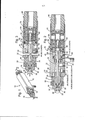
[00011] A Fig. 1 é uma vista em perspectiva de um conjunto de bocais de pulverização exemplificativo com um conjunto de válvulas magneticamente acionado de acordo com a presente invenção.[00011] Fig. 1 is a perspective view of an exemplary spray nozzle assembly with a magnetically driven valve assembly in accordance with the present invention.
[00012] A Fig. 2 é uma vista em seção transversal do conjunto de bocais de pulverização da Fig. 1 tomada no plano da linha 2-2 da Fig. 1 que mostra o conjunto de válvulas na posição fechada.[00012] Fig. 2 is a cross-sectional view of the set of spray nozzles of Fig. 1 taken on the plane of line 2-2 of Fig. 1 showing the valve set in the closed position.
[00013] A Fig. 3 é uma vista em seção transversal, fragmentada do conjunto de bocais de pulverização da Fig. 1 similar a Fig. 2, porém mostrando o conjunto de válvulas na posição aberta.[00013] Fig. 3 is a fragmentary cross-sectional view of the set of spray nozzles in Fig. 1 similar to Fig. 2, but showing the valve set in the open position.
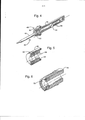
[00014] A Fig. 4 é uma vista em seção transversal parcial, em perspectiva do conjunto de válvulas do conjunto de bocais de pulverização da Fig. 1.[00014] Fig. 4 is a partial cross-sectional view, in perspective of the valve set of the spray nozzle set of Fig. 1.
[00015] A Fig. 5 é uma vista em seção transversal, em perspectiva do conjunto de pistões do conjunto de bocais de pulverização da Fig. 1.[00015] Fig. 5 is a cross-sectional perspective view of the piston assembly of the spray nozzle assembly of Fig. 1.
[00016] A Fig. 6 é uma vista em seção transversal, em perspectiva do conjunto de tampas de extremidade do conjunto de bocais de pulverização da Fig. 1 que mostra o arranjo de retorno de válvula magnética.[00016] Fig. 6 is a cross-sectional, perspective view of the end cap set of the spray nozzle set of Fig. 1 showing the magnetic valve return arrangement.
[00017] A Fig. 7 é uma vista em seção lateral de uma modalidade alternativa de um conjunto de bocais de pulverização de acordo com a presente invenção que inclui um arranjo de retorno de válvula de mola.[00017] Fig. 7 is a side section view of an alternative embodiment of a set of spray nozzles according to the present invention that includes a spring valve return arrangement.
[00018] Embora a invenção seja suscetível a diversas modificações e construções alternativas, certas modalidades ilustrativas da mesma foram mostradas nos desenhos e serão descritas em detalhes abaixo. Entende-se, contudo, que não há intenção em limitar a invenção à forma especifica descrita, porém o contrário, a intenção é cobrir todas as modificações, construções alternativas, e equivalentes que entrem no espirito e âmbito da invenção.[00018] Although the invention is susceptible to several modifications and alternative constructions, certain illustrative modalities of it have been shown in the drawings and will be described in detail below. It is understood, however, that there is no intention to limit the invention to the specific form described, however the opposite, the intention is to cover all modifications, alternative constructions, and equivalents that enter the spirit and scope of the invention.
[00019] Em relação agora mais especificamente as Figs. 1-3 dos desenhos, é mostrado um conjunto de bocais de pulverização 10 de acordo com a invenção. Neste caso, o conjunto de bocais de pulverização 10 geralmente compreende uma porção de corpo 12, um bocal de pulverização 14 montado sobre a porção de corpo e uma tampa de ar 16 sobre o bocal de pulverização 14. A estrutura básica e operação do conjunto de bocais de pulverização são conhecidas na técnica, por exemplo, conforme descrito na Patente U.S. No. 5.707.010. A estrutura global e operação do conjunto de bocais de pulverização deveriam ser entendidas como sendo ilustrativas de apenas um exemplo de um dispositivo de pulverização com o qual a presente invenção pode ser utilizada.[00019] In relation now more specifically to Figs. 1-3 of the drawings, a set of
[00020] Neste caso, a porção de corpo 12 inclui as entradas para diversos fornecimentos de fluido associados com a operação do conjunto de bocais de pulverização conforme mostrado nas Figs. 2 e 3. Especificamente, a porção de corpo ilustrada 12 inclui uma porta de entrada de fluido de aplicação 18 para conexão a um fornecimento de fluido de aplicação a ser pulverizado e uma porta de fluido auxiliar 20 para conexão com uma fonte de ar pressurizado (por exemplo, ar pressurizado) utilizada para atomizar o fluido de aplicação sendo pulverizado. A porta de entrada de fluido de aplicação 18 comunica-se com uma passagem de fluido central 22 na porção de corpo 12.[00020] In this case, the
[00021] O bocal de pulverização 14 é fixado à jusante ou extremidade de descarga da porção de corpo 12 por uma haste rosqueada 24 engatável na passagem de fluido central 22 na porção de corpo. A tampa de ar 16, por sua vez, é montada sobre a extremidade a jusante do bocal de pulverização 14 por uma porca de retenção 26 que engata uma aba sobre a tampa de ar 16 e rosqueia sobre a extremidade de bocal de pulverização 14. Para direcionar o fluido de aplicação através do conjunto de bocais 10, o bocal de pulverização 14 inclui uma passagem de fluido central 28 que se comunica com uma passagem de fluido central 22 na porção de corpo 12. O bocal de pulverização 14 inclui ainda diversas passagens de fluido de atomização 30 que se comunicam com um cano de distribuição anular 32 na porção de corpo 12, que, por sua vez, está em comunicação com a porta de entrada de fluido auxiliar de atomização 20.[00021] The
[00022] O bocal de pulverização 14 inclui uma porção dianteira que se estende para frente 34 que define um orificio de descarga de fluido 35. A porção dianteira 34 do bocal de pulverização 14 estende-se para fora a partir do corpo de bocal de pulverização para dentro e através de uma câmara de ar 36 que é definida em torno da extremidade a jusante do corpo de bocal pela tampa de ar 16. A porção dianteira 34 termina em uma passagem de descarga central 38 na tampa de ar 16 que se estende a jusante a partir da câmara de ar 36. A porção dianteira 34 é ligeiramente menor em diâmetro do que a passagem de descarga central 38 na tampa de ar 16 de modo que um orificio anular seja propiciado em torno da porção dianteira 34 através da qual o fluido de atomização é descarregado paralelo a e para dentro do fluido de aplicação sendo descarregado através do orificio de descarga de fluido de aplicação 35.[00022] The
[00023] Para controlar o fluxo de fluido de aplicação através do orificio de descarga 35 no bocal de pulverização, o conjunto de bocais de pulverização 10 inclui um conjunto de válvulas 40 que inclui uma agulha de válvula 42 que é móvel entre as posições aberta (vide Fig. 3) e fechada (vide Fig. 2) . Na modalidade ilustrada, a agulha de válvula 42 é um elemento cilíndrico longo que é sustentado pela porção de corpo 12 e se estende axialmente através das passagens de fluido central na porção de corpo e o bocal de pulverização 22, 28 até o orificio de descarga 35. Na posição fechada, conforme mostrado na Fig. 2, uma porção de extremidade distal da agulha de válvula 42 engata e assenta contra uma superfície interna do orificio de descarga 35 bloqueando deste modo o fluido de aplicação na passagem central 28 do bocal de pulverização 14 de sair através do orificio de descarga. Na posição aberta, conforme mostrado na Fig. 3, a porção de extremidade da agulha de válvula 42 é retraída para longe do orificio de descarga 35 de modo que o fluido de aplicação possa fluir através do orificio de descarga e para fora do conjunto de bocais de pulverização 10.[00023] To control the flow of application fluid through the
[00024] A agulha de válvula 42 é sustentada para reciprocidade, movimento axial em um tubo de guia 44 que é parte de um conjunto de tubos de guia 45 incluído na porção de corpo. Neste caso, a porção de corpo 12 compreende uma seção dianteira 46 que inclui a passagem de fluido central 22 e as entradas de fluido de aplicação e atomização, o conjunto de tubos de guia 45 e uma tampa de extremidade 48. O conjunto de tubos de guia 45 é arrumado em um recesso de abertura voltado para a parte posterior na seção dianteira 46 do corpo e inclui uma haste rosqueada 50 que engata roscas complementares na extremidade adiantada do recesso. A tampa de extremidade 48, por sua vez, rosqueia sobre a extremidade posterior da seção dianteira 46 e também engata a extremidade posterior do conjunto de tubos de guia 45. Quando fixado à seção dianteira 46 da porção de corpo 12, o tubo de guia 44 comunica-se com a passagem de fluido central 22 de modo que o fluido de aplicação introduzido através da entrada 18 circule em torno da agulha de válvula 42 em ambas as passagens de fluido central na seção dianteira e no bocal de pulverização 18, 28 bem como no tubo de guia 44.[00024] Valve
[00025] Na modalidade ilustrada, a agulha de válvula 42 desliza para frente no tubo de guia 44 para alcançar a posição fechada e na direção posterior para alcançar a posição aberta. Para facilitar este movimento de deslizamento, uma guia de agulha 52 é arrumada sobre a agulha de válvula 42 próxima à extremidade adiantada da mesma. Conforme mostrado na Fig. 4, a guia de agulha 52, neste caso, possui diversos membros que se estendem radialmente que definem uma série de aberturas estriadas que permitem que o fluido de aplicação passe a guia de agulha e deste modo circule através do tubo de guia 44. A agulha de válvula 42 é ainda sustentada para movimento de deslizamento no tubo de guia 44 por uma seção alargada 54 que é arrumada mais próxima à extremidade posterior da agulha de válvula 42. Novamente, para permitir a circulação do fluido de aplicação através do tubo de guia 44, a seção alargada 54 da agulha de válvula 42 possui lados planos opostos que definem aberturas entre a seção alargada 54 e a parede interna do tubo de guia 44 através do qual o fluido de aplicação pode fluir (vide Fig. 4).[00025] In the illustrated embodiment,
[00026] De acordo com um aspecto importante da presente invenção, para efetivar movimento da agulha de válvula 42 entre as posições aberta e fechada, o conjunto de válvula 40 inclui um conjunto de pistões acionados por fluido 56 que incorpora um carro móvel 58 que possui um acoplamento não mecânico com a agulha de válvula 42 que permite a agulha de válvula mover com o carro (vide Figs. 2 e 3) . Ao realizar a invenção, a agulha de válvula 42 é acoplada ao carro 58 por meio de um campo magnético para movimento simultâneo com o carro durante acionamento através de um fluido de controle pressurizado, por exemplo, ar pressurizado. Com este arranjo, não há necessidade de ter qualquer acondicionamento gotejante ou vedações separam o fluido de controle do fluido de aplicação à medida que o tubo de guia define uma parede sólida que propicia tal separação. Sendo assim, o potencial para vazamento do fluido de controle é substancialmente reduzido. Além disso, a eliminação do acondicionamento ou vedações remove uma fonte significativa de arrasto no movimento da agulha de válvula. Como resultado, o conjunto de bocais de pulverização pode ser mais confiavelmente operado em pressões de fluido de controle relativamente baixas e um número maior de conjuntos de bocais de pulverização pode ser utilizado em uma aplicação especifica com um fornecimento de fluido de controle pressurizado determinado.[00026] In accordance with an important aspect of the present invention, to effect movement of the
[00027] Na modalidade ilustrada, o conjunto de pistões 5 6 é arrumado em uma câmara de ar de controle 60 que é definida no espaço entre a superfície externa do tubo de guia 44 e a superfície interna do recesso na seção dianteira 46 da porção de corpo 12. O carro 58 do conjunto de pistões é sustentado sobre o tubo de guia 44 para movimento de deslizamento para frente e para trás na câmara de ar de controle 60. O carro 58 é de preferência feito de um material de baixa fricção tal como Teflon® a fim de facilitar o movimento de deslizamento no tubo de guia 44. Um anel de vedação 62 é arrumado em uma ranhura sobre a superfície externa do carro para garantir uma vedação apertada contra a superfície interna da porção de corpo.[00027] In the illustrated embodiment, the piston set 5 6 is arranged in a
[00028] Para propiciar a conexão magnética entre o conjunto de pistões 56 e a agulha de válvula 42, o carro 58 inclui um recesso em formato de cálice no qual, neste caso, dois imãs anulares externos 64 são arrumados. Um anel de arame 65 é arrumado adjacente à extremidade de abertura do recesso em formato de cálice para auxiliar a reter os imãs no recesso conforme mostrado na Fig. 5. Um par de imãs anulares internos 66 que possui um diâmetro relativamente menor do que os imãs anulares externos é, por sua vez, fixado sobre a agulha de válvula 42 (vide Figs. 2 e 3) . Especificamente, os imãs anulares internos 66 são arrumados sobre a agulha de válvula 42 de modo que os mesmos estejam radialmente para dentro dos imãs anulares externos 64 com os imãs anulares externos em relação circundante aos imãs anulares internos.[00028] To provide the magnetic connection between the piston set 56 and the
[00029] Os imãs anulares externos e internos 64, 66 são magnetizados na direção axial com os pólos magnéticos arrumados em extremidades axiais opostas de cada um dos imãs anulares. Além disso, os imãs anulares internos 66 são arrumados de modo que seus pólos sejam arrumados na orientação oposta dos pólos dos imãs anulares externos 64. Especificamente, os pólos norte dos imãs anulares internos 66 são alinhados com pólos sul dos imãs anulares externos 64 e os pólos sul dos imãs anulares internos são alinhados com os pólos norte dos imãs anulares externos conforme mostrado nas Figs. 2 e 3. Este alinhamento garante que exista uma conexão magnética forte, boa entre os imãs anulares externos e internos 64, 66. Os imãs anulares externos e internos 64, 66 podem ser construídos de qualquer material magnético adequado. Um tipo adequado de imã que pode ser utilizado é um imã terrestre raro de neodimio. De acordo com uma modalidade, os imãs anulares externos e internos podem ser imãs de neodimio taxados de N42 .[00029] The external and internal
[00030] O movimento de deslizamento do carro 58 é direcionado pelo fluxo de fluido de controle pressurizado para a câmara de ar de controle 60. Para este fim, a porção de corpo 12 inclui uma porta de entrada de fluido de controle 68 em comunicação com a câmara de ar de controle 60 que pode ser conectada a um fornecimento de fluido de controle pressurizado. Quando o ar de controle pressurizado é direcionado através da entrada 68 e para dentro da câmara de ar 60, o ar de controle pressurizado força o carro 58, e com o mesmo os imãs anulares externos 64, para a parte posterior no tubo de guia 44 (vide Fig. 3) . Por causa da conexão magnética entre os imãs anulares externos e internos 64, 66, este movimento dos imãs anulares externos 66 puxa os imãs anulares internos 64, e com os mesmos a agulha de válvula 42, na direção posterior para dentro da posição aberta. Devido à forte atração magnética entre os imãs anulares externos e internos 64, 66, o movimento da agulha de válvula 42 pode ser controlado sem qualquer conexão fisica entre a agulha de válvula e o conjunto de pistões.[00030] The sliding movement of the
[00031] Além de manter com a invenção, o conjunto de pistões 56 pode possuir um arranjo de retorno de agulha de válvula não mecânica para retornar a agulha de válvula 42 para sua posição fechada, assentada. Para este fim, um imã anular adicional 70 é colocado na direção posterior da agulha de válvula 42 em um recesso definido na tampa de extremidade 48 da porção de corpo 12 (vide Figs. 2, 3 e 6). Como com os imãs anulares externos e internos 64, 66, o imã anular posterior 70 é magnetizado na direção axial de modo que os pólos opostos do imã sejam arrumados em extremidades axiais opostas. Neste caso, o imã anular posterior 70 é substancialmente do mesmo diâmetro dos imãs anulares externos 64 sustentados no carro 58. Além disso, o imã anular posterior 70 é arrumado com seus pólos orientados opostamente àqueles dos imãs anulares externos 64. Por exemplo, na modalidade ilustrada, o pólo sul do imã anular posterior 70 se volta para o pólo sul do imã anular externo mais posterior 64. Desta forma, o imã anular posterior 70 empurra ou inclina o carro 58 para frente na direção de fechamento de válvula.[00031] In addition to maintaining with the invention, the
[00032] A pressão do fluido de controle na câmara de ar de controle 60 deve ser suficiente para superar esta força de inclinação magnética quando o carro 58 é acionado na direção posterior para mover a agulha de válvula 42 para a posição aberta. Quando o fornecimento de fluido de controle pressurizado para a câmara de ar de controle 60 é desligado, a força de inclinação magnética criada pelo imã anular posterior 70 e os imãs anulares externos 64 volta o carro 58 e deste modo a agulha de válvula 42 para a posição fechada (vide Fig. 2). 0 fornecimento de fluido de controle para a entrada 68 é controlado externamente, tal como por válvulas acionadas por solenoide. Através de tal controle do fluxo de fluido de controle para a entrada 68, a agulha de válvula 42 pode ser seletivamente movida entre as posições aberta e fechada, incluindo a operação do conjunto de agulha de válvula em um modo liga-desliga ciclico de velocidade elevada.[00032] The pressure of the control fluid in the
[00033] Um arranjo de retorno de agulha de válvula alternativo é ilustrado na Fig. 7. Neste arranjo, uma mola de compressão de mola 70 é confinada entre um recesso na tampa de extremidade 48 da porção de corpo 12 e a extremidade posterior do carro 58. Como o imã anular posterior das Figs. 2 e 3, a mola de compressão 70 inclina o conjunto de pistões 58 e conseqüentemente a agulha de válvula 42 para frente até uma posição fechada completamente assentada através da atração magnética entre os imãs anulares externos e internos 64, 66.[00033] An alternative valve needle return arrangement is illustrated in Fig. 7. In this arrangement, a
[00034] Todas as referências, incluindo publicações, pedidos de patentes, e patentes, citados aqui são pela mesma incorporados mediante referência à mesma extensão como se cada referência fosse individual e especificamente indicada para ser incorporada mediante referência e fosse estabelecida anteriormente em sua totalidade aqui.[00034] All references, including publications, patent applications, and patents, cited here are hereby incorporated by reference to the same extent as if each reference were individually and specifically indicated to be incorporated by reference and were previously established in its entirety here .
[00035] O uso dos termos "um" e "uma" e "o" e referências similares no contexto de descrever a invenção (especialmente no contexto das reivindicações que se seguem) deve ser construído para cobrir tanto o singular quanto o plural, a não ser que de outra forma indicada aqui ou claramente contradita pelo contexto. Os termos "que compreende", "que possui", "que inclui" e "que contém" devem ser construídos como termos de finalidade aberta (isto é, significando "incluindo, porém não limitado a,") a não ser que de outra forma observado. Citação de faixas de valores aqui é meramente destinada a servir como um método à mão de referir-se individualmente a cada valor separado que entra dentro da faixa, a não ser que de outra forma indicada aqui, e cada valor separado é incorporado na especificação como se fosse individualmente citado aqui. Todos os métodos descritos aqui podem ser realizados em qualquer ordem adequada a não ser que de outra forma indicada aqui ou de outra forma claramente contradito pelo contexto. 0 uso de qualquer e todos os exemplos, ou linguagem exemplificativa (por exemplo, "tal como") propiciada aqui, destina-se meramente a melhor iluminar a invenção e não impõe uma limitação sobre o âmbito da invenção a não ser que de outra forma reivindicado. Nenhuma linguagem na especificação deveria ser construída como indicando qualquer elemento não reivindicado como essencial para a prática da invenção.[00035] The use of the terms "one" and "one" and "o" and similar references in the context of describing the invention (especially in the context of the claims that follow) should be constructed to cover both the singular and the plural, the unless otherwise indicated here or clearly contradicted by the context. The terms "that understands", "that owns", "that includes" and "that contains" must be constructed as open-ended terms (ie, meaning "including, but not limited to,") unless otherwise observed way. Quotation of ranges of values here is merely intended to serve as a handy method of referring individually to each separate value that falls within the range, unless otherwise indicated here, and each separate value is incorporated into the specification as if it were individually quoted here. All of the methods described here can be performed in any suitable order unless otherwise indicated here or otherwise clearly contradicted by the context. The use of any and all examples, or exemplary language (for example, "such as") provided herein, is intended merely to better illuminate the invention and does not impose a limitation on the scope of the invention unless otherwise claimed. No language in the specification should be constructed as indicating any element not claimed as essential to the practice of the invention.
[00036] Modalidades preferidas desta invenção são descritas aqui, incluindo o melhor modo conhecido para os inventores para realizar a invenção. Variações daquelas modalidades preferidas podem tornar-se evidentes àqueles versados na técnica durante a leitura da descrição anterior. Os inventores esperam que versados na técnica empreguem tais variações conforme apropriado, e os inventores pretendem que a invenção seja praticada de outra forma que conforme especificamente descrita aqui. Conseqüentemente, esta invenção inclui todas as modificações e equivalentes da matéria objeto citada nas reivindicações em anexo à mesma conforme permitido pela lei aplicável. Além disso, qualquer combinação dos elementos acima descritos em todas as variações possíveis dos mesmos é abrangida pela invenção a não ser que de outra forma indicada aqui ou de outra forma claramente contradita pelo contexto.[00036] Preferred embodiments of this invention are described here, including the best known way for the inventors to carry out the invention. Variations of those preferred embodiments may become evident to those skilled in the art when reading the previous description. The inventors expect those skilled in the art to employ such variations as appropriate, and the inventors intend for the invention to be practiced in a manner other than as specifically described herein. Consequently, this invention includes all modifications and equivalents of the subject matter mentioned in the claims attached to it as permitted by applicable law. In addition, any combination of the elements described above in all possible variations thereof is covered by the invention unless otherwise indicated here or otherwise clearly contradicted by the context.
Claims (4)
Applications Claiming Priority (3)
| Application Number | Priority Date | Filing Date | Title |
|---|---|---|---|
| US89700607P | 2007-01-23 | 2007-01-23 | |
| US60/897,006 | 2007-01-23 | ||
| PCT/US2008/000874 WO2008091635A2 (en) | 2007-01-23 | 2008-01-23 | Air atomizing spray nozzle with magnetically actuated shutoff valve |
Publications (2)
| Publication Number | Publication Date |
|---|---|
| BRPI0807414A2 BRPI0807414A2 (en) | 2014-05-20 |
| BRPI0807414B1 true BRPI0807414B1 (en) | 2020-10-06 |
Family
ID=39645067
Family Applications (1)
| Application Number | Title | Priority Date | Filing Date |
|---|---|---|---|
| BRPI0807414-3A BRPI0807414B1 (en) | 2007-01-23 | 2008-01-23 | SPRAYING DEVICE |
Country Status (10)
| Country | Link |
|---|---|
| US (1) | US7789325B2 (en) |
| EP (1) | EP2117720B1 (en) |
| JP (1) | JP5245142B2 (en) |
| CN (1) | CN101588872B (en) |
| AU (1) | AU2008209476B2 (en) |
| BR (1) | BRPI0807414B1 (en) |
| DK (1) | DK2117720T3 (en) |
| ES (1) | ES2535214T3 (en) |
| PL (1) | PL2117720T3 (en) |
| WO (1) | WO2008091635A2 (en) |
Families Citing this family (11)
| Publication number | Priority date | Publication date | Assignee | Title |
|---|---|---|---|---|
| KR20100114502A (en) * | 2007-12-22 | 2010-10-25 | 프리메트 프리시젼 머테리알스, 인크. | Small particle electrode material compositions and methods of forming the same |
| US8575921B1 (en) * | 2008-09-12 | 2013-11-05 | Christopher John Sloan | Position indicator apparatus and method |
| US8939387B2 (en) * | 2010-05-03 | 2015-01-27 | Chapin Manufacturing, Inc. | Spray gun |
| CN102162549B (en) * | 2011-04-15 | 2012-01-25 | 黄石市海成节能科技开发有限公司 | Magnetic dipole valve |
| FR2976506A1 (en) * | 2011-06-15 | 2012-12-21 | Chanel Parfums Beaute | DEVICE FOR DISPENSING A FLUID PRODUCT FOR CARE, MAKE-UP OR TOILET |
| EP2700807A1 (en) * | 2012-08-23 | 2014-02-26 | Continental Automotive GmbH | Valve assembly for an injection valve and injection valve |
| DE102013006106A1 (en) * | 2013-04-09 | 2014-10-09 | Delo Industrie Klebstoffe Gmbh & Co. Kgaa | metering |
| JP6792293B2 (en) | 2015-04-15 | 2020-11-25 | ユニバーシティー オブ デラウェア | Equipment, systems and methods for variable flow fuel emissions |
| CN106925461A (en) * | 2017-05-02 | 2017-07-07 | 广东贺尔环境技术有限公司 | Gas-vapor mix atomizing component |
| CN107088484B (en) * | 2017-06-28 | 2023-07-18 | 迈德乐喷雾系统广州有限公司 | Small-sized air atomizing nozzle |
| EP3725416A4 (en) * | 2017-12-12 | 2021-08-04 | Jong-Su Park | Coaxial control dual nozzle |
Family Cites Families (12)
| Publication number | Priority date | Publication date | Assignee | Title |
|---|---|---|---|---|
| US3224677A (en) * | 1964-09-14 | 1965-12-21 | Kelroy Corp | Vaporizing apparatus |
| DE1919708A1 (en) * | 1969-04-18 | 1970-11-12 | Bosch Gmbh Robert | Solenoid valve for short response times |
| US4637427A (en) * | 1983-09-14 | 1987-01-20 | Nolan John H | Magnetic valve |
| JPH0633271Y2 (en) * | 1988-02-29 | 1994-08-31 | トリニティ工業株式会社 | Paint supply valve |
| JPH05168984A (en) * | 1991-12-20 | 1993-07-02 | Asahi Sanac Kk | Spray gun for coating |
| CN2217470Y (en) * | 1994-11-17 | 1996-01-17 | 东北电力学院自控技术开发公司 | Anti-blocked spray head |
| US6182904B1 (en) * | 1997-04-22 | 2001-02-06 | Board Of Trustees Operating Michigan State University | Automated electronically controlled microsprayer |
| DE19910261B4 (en) * | 1999-03-08 | 2004-12-09 | Alfred Schütze Apparatebau GmbH | spray valve |
| JP2001021060A (en) * | 1999-07-06 | 2001-01-26 | Fukuda:Kk | Valve device |
| US20040195401A1 (en) * | 2003-02-28 | 2004-10-07 | Strong Christopher L. | Repeatable mounting unit for automatic spray device |
| US7416607B2 (en) * | 2005-05-25 | 2008-08-26 | Taiwan Semiconductor Manufacturing Co., Ltd. | Fluid injection apparatus for semiconductor processing |
| DE102006007514A1 (en) * | 2006-02-16 | 2007-08-23 | Günter Troska | Fluid-operated linear drive for a magnetic valve of a paint spray gun comprises a piston rod and a piston each having magnets assigned to each other to linearly move the rod as a result of the linear movement of the piston |
-
2008
- 2008-01-23 WO PCT/US2008/000874 patent/WO2008091635A2/en active Application Filing
- 2008-01-23 JP JP2009546452A patent/JP5245142B2/en active Active
- 2008-01-23 PL PL08724727T patent/PL2117720T3/en unknown
- 2008-01-23 CN CN2008800029854A patent/CN101588872B/en active Active
- 2008-01-23 EP EP08724727.6A patent/EP2117720B1/en active Active
- 2008-01-23 DK DK08724727T patent/DK2117720T3/en active
- 2008-01-23 ES ES08724727.6T patent/ES2535214T3/en active Active
- 2008-01-23 BR BRPI0807414-3A patent/BRPI0807414B1/en active IP Right Grant
- 2008-01-23 US US12/009,870 patent/US7789325B2/en active Active
- 2008-01-23 AU AU2008209476A patent/AU2008209476B2/en active Active
Also Published As
| Publication number | Publication date |
|---|---|
| CN101588872A (en) | 2009-11-25 |
| EP2117720B1 (en) | 2015-02-25 |
| AU2008209476B2 (en) | 2012-02-02 |
| EP2117720A4 (en) | 2012-12-12 |
| PL2117720T3 (en) | 2015-06-30 |
| US7789325B2 (en) | 2010-09-07 |
| WO2008091635A3 (en) | 2008-11-13 |
| BRPI0807414A2 (en) | 2014-05-20 |
| WO2008091635A2 (en) | 2008-07-31 |
| ES2535214T3 (en) | 2015-05-06 |
| CN101588872B (en) | 2012-12-05 |
| WO2008091635A9 (en) | 2008-10-02 |
| EP2117720A2 (en) | 2009-11-18 |
| AU2008209476A1 (en) | 2008-07-31 |
| DK2117720T3 (en) | 2015-05-04 |
| JP2010516447A (en) | 2010-05-20 |
| US20090121167A1 (en) | 2009-05-14 |
| JP5245142B2 (en) | 2013-07-24 |
Similar Documents
| Publication | Publication Date | Title |
|---|---|---|
| BRPI0807414B1 (en) | SPRAYING DEVICE | |
| US3317184A (en) | Pintle valve and flow collimator | |
| BRPI0809508B1 (en) | solenoid operated valve unit. | |
| JP5790979B2 (en) | Valve device for irrigation system | |
| ES2804125T3 (en) | Fill needle for filling a container with a fluid | |
| CN106030175A (en) | Multipurpose flow control arrangement | |
| CN102927332A (en) | Piston type control valve | |
| CN105466088B (en) | Heating power expansion valve and heat pump system with the heating power expansion valve | |
| CN106286892B (en) | Three-way magnetic valve | |
| ES2373554T3 (en) | DISK TYPE VALVE FOR FLOW CONTROL. | |
| CN103807205B (en) | For the lid with the cooperation of the flow control component of the valve of self-priming electrodynamic pump | |
| CN106286893B (en) | Three-way magnetic valve | |
| CN106286895B (en) | Three-way magnetic valve | |
| CN109013083A (en) | A kind of integration liquid-gas two-phase flow body delicate metering spray solenoid valve | |
| CN106286894B (en) | Three-way magnetic valve | |
| KR20110067338A (en) | Shut-off nozzle | |
| CN207864656U (en) | Double valve gas spray valve | |
| CN206966019U (en) | Slide disconnected glue glue dispensing valve | |
| CN107084076B (en) | Integrated annular manifold wall surface gas fuel injection mixing device for mixed air intake | |
| CN110529315A (en) | A kind of inlet valve, high-pressure oil pump and engine | |
| CN106288547B (en) | A kind of heating power expansion valve of the unidirectionally controlled function of band | |
| CN110185566A (en) | A kind of spiral-flow type jet orifice plate and nozzle | |
| CN108266549A (en) | A kind of pressure-control check valve | |
| CN107990141A (en) | A kind of oxygen storage tank with equivalent decompression | |
| CN109092582A (en) | A kind of liquid-gas two-phase flow body delicate metering spray solenoid valve |
Legal Events
| Date | Code | Title | Description |
|---|---|---|---|
| B06F | Objections, documents and/or translations needed after an examination request according [chapter 6.6 patent gazette] | ||
| B06T | Formal requirements before examination [chapter 6.20 patent gazette] | ||
| B09A | Decision: intention to grant [chapter 9.1 patent gazette] | ||
| B16A | Patent or certificate of addition of invention granted [chapter 16.1 patent gazette] |
Free format text: PRAZO DE VALIDADE: 10 (DEZ) ANOS CONTADOS A PARTIR DE 06/10/2020, OBSERVADAS AS CONDICOES LEGAIS. |