BRPI0807331B1 - PARTICLE SEPARATION METHOD - Google Patents
PARTICLE SEPARATION METHOD Download PDFInfo
- Publication number
- BRPI0807331B1 BRPI0807331B1 BRPI0807331-7A BRPI0807331A BRPI0807331B1 BR PI0807331 B1 BRPI0807331 B1 BR PI0807331B1 BR PI0807331 A BRPI0807331 A BR PI0807331A BR PI0807331 B1 BRPI0807331 B1 BR PI0807331B1
- Authority
- BR
- Brazil
- Prior art keywords
- particles
- fluidized bed
- bubbles
- bed
- liquid
- Prior art date
Links
- 239000002245 particle Substances 0.000 title claims abstract description 162
- 238000000926 separation method Methods 0.000 title claims abstract description 12
- 238000005188 flotation Methods 0.000 claims abstract description 62
- 238000004062 sedimentation Methods 0.000 claims abstract description 34
- 230000002209 hydrophobic effect Effects 0.000 claims abstract description 31
- 239000006260 foam Substances 0.000 claims abstract description 29
- 239000012530 fluid Substances 0.000 claims abstract description 27
- 238000000034 method Methods 0.000 claims abstract description 25
- 239000000203 mixture Substances 0.000 claims abstract description 10
- 239000007788 liquid Substances 0.000 claims description 63
- 238000004064 recycling Methods 0.000 claims description 27
- 238000005276 aerator Methods 0.000 claims description 7
- 230000015572 biosynthetic process Effects 0.000 claims description 6
- 230000000630 rising effect Effects 0.000 claims description 5
- 230000003134 recirculating effect Effects 0.000 abstract description 2
- 239000007787 solid Substances 0.000 description 44
- XLYOFNOQVPJJNP-UHFFFAOYSA-N water Substances O XLYOFNOQVPJJNP-UHFFFAOYSA-N 0.000 description 38
- 238000005243 fluidization Methods 0.000 description 27
- 239000002699 waste material Substances 0.000 description 16
- 230000008569 process Effects 0.000 description 14
- 239000000725 suspension Substances 0.000 description 11
- 239000011362 coarse particle Substances 0.000 description 9
- 238000005516 engineering process Methods 0.000 description 6
- 239000003380 propellant Substances 0.000 description 6
- 238000011084 recovery Methods 0.000 description 5
- 230000008901 benefit Effects 0.000 description 4
- 239000003153 chemical reaction reagent Substances 0.000 description 4
- 238000000605 extraction Methods 0.000 description 4
- 230000005484 gravity Effects 0.000 description 4
- 230000009467 reduction Effects 0.000 description 4
- 239000002002 slurry Substances 0.000 description 4
- 230000009471 action Effects 0.000 description 3
- 230000001143 conditioned effect Effects 0.000 description 3
- 230000007423 decrease Effects 0.000 description 3
- 239000000945 filler Substances 0.000 description 3
- 229910052500 inorganic mineral Inorganic materials 0.000 description 3
- 239000011707 mineral Substances 0.000 description 3
- 238000011144 upstream manufacturing Methods 0.000 description 3
- 238000005273 aeration Methods 0.000 description 2
- 230000001174 ascending effect Effects 0.000 description 2
- 230000000694 effects Effects 0.000 description 2
- 238000002347 injection Methods 0.000 description 2
- 239000007924 injection Substances 0.000 description 2
- 239000000463 material Substances 0.000 description 2
- 230000000149 penetrating effect Effects 0.000 description 2
- 239000011435 rock Substances 0.000 description 2
- OKTJSMMVPCPJKN-UHFFFAOYSA-N Carbon Chemical compound [C] OKTJSMMVPCPJKN-UHFFFAOYSA-N 0.000 description 1
- 238000013019 agitation Methods 0.000 description 1
- 239000007900 aqueous suspension Substances 0.000 description 1
- 239000010953 base metal Substances 0.000 description 1
- 230000000903 blocking effect Effects 0.000 description 1
- 229910052799 carbon Inorganic materials 0.000 description 1
- 230000008859 change Effects 0.000 description 1
- 230000003750 conditioning effect Effects 0.000 description 1
- 239000000470 constituent Substances 0.000 description 1
- 230000007797 corrosion Effects 0.000 description 1
- 238000005260 corrosion Methods 0.000 description 1
- 230000003247 decreasing effect Effects 0.000 description 1
- 230000007812 deficiency Effects 0.000 description 1
- 230000018044 dehydration Effects 0.000 description 1
- 238000006297 dehydration reaction Methods 0.000 description 1
- 230000009977 dual effect Effects 0.000 description 1
- 230000002349 favourable effect Effects 0.000 description 1
- 238000007667 floating Methods 0.000 description 1
- 239000004088 foaming agent Substances 0.000 description 1
- 239000013505 freshwater Substances 0.000 description 1
- 238000009499 grossing Methods 0.000 description 1
- 238000011835 investigation Methods 0.000 description 1
- 238000012423 maintenance Methods 0.000 description 1
- 230000014759 maintenance of location Effects 0.000 description 1
- 230000007257 malfunction Effects 0.000 description 1
- 229910052976 metal sulfide Inorganic materials 0.000 description 1
- 238000005065 mining Methods 0.000 description 1
- 230000000704 physical effect Effects 0.000 description 1
- 230000004044 response Effects 0.000 description 1
- 239000007921 spray Substances 0.000 description 1
- 230000003068 static effect Effects 0.000 description 1
- 239000002352 surface water Substances 0.000 description 1
- 230000002459 sustained effect Effects 0.000 description 1
Images
Classifications
-
- B—PERFORMING OPERATIONS; TRANSPORTING
- B03—SEPARATION OF SOLID MATERIALS USING LIQUIDS OR USING PNEUMATIC TABLES OR JIGS; MAGNETIC OR ELECTROSTATIC SEPARATION OF SOLID MATERIALS FROM SOLID MATERIALS OR FLUIDS; SEPARATION BY HIGH-VOLTAGE ELECTRIC FIELDS
- B03D—FLOTATION; DIFFERENTIAL SEDIMENTATION
- B03D1/00—Flotation
- B03D1/14—Flotation machines
- B03D1/24—Pneumatic
-
- B—PERFORMING OPERATIONS; TRANSPORTING
- B03—SEPARATION OF SOLID MATERIALS USING LIQUIDS OR USING PNEUMATIC TABLES OR JIGS; MAGNETIC OR ELECTROSTATIC SEPARATION OF SOLID MATERIALS FROM SOLID MATERIALS OR FLUIDS; SEPARATION BY HIGH-VOLTAGE ELECTRIC FIELDS
- B03D—FLOTATION; DIFFERENTIAL SEDIMENTATION
- B03D1/00—Flotation
- B03D1/02—Froth-flotation processes
- B03D1/028—Control and monitoring of flotation processes; computer models therefor
-
- B—PERFORMING OPERATIONS; TRANSPORTING
- B03—SEPARATION OF SOLID MATERIALS USING LIQUIDS OR USING PNEUMATIC TABLES OR JIGS; MAGNETIC OR ELECTROSTATIC SEPARATION OF SOLID MATERIALS FROM SOLID MATERIALS OR FLUIDS; SEPARATION BY HIGH-VOLTAGE ELECTRIC FIELDS
- B03D—FLOTATION; DIFFERENTIAL SEDIMENTATION
- B03D1/00—Flotation
- B03D1/08—Subsequent treatment of concentrated product
- B03D1/082—Subsequent treatment of concentrated product of the froth product, e.g. washing
-
- B—PERFORMING OPERATIONS; TRANSPORTING
- B03—SEPARATION OF SOLID MATERIALS USING LIQUIDS OR USING PNEUMATIC TABLES OR JIGS; MAGNETIC OR ELECTROSTATIC SEPARATION OF SOLID MATERIALS FROM SOLID MATERIALS OR FLUIDS; SEPARATION BY HIGH-VOLTAGE ELECTRIC FIELDS
- B03D—FLOTATION; DIFFERENTIAL SEDIMENTATION
- B03D1/00—Flotation
- B03D1/14—Flotation machines
- B03D1/1443—Feed or discharge mechanisms for flotation tanks
- B03D1/1456—Feed mechanisms for the slurry
-
- B—PERFORMING OPERATIONS; TRANSPORTING
- B03—SEPARATION OF SOLID MATERIALS USING LIQUIDS OR USING PNEUMATIC TABLES OR JIGS; MAGNETIC OR ELECTROSTATIC SEPARATION OF SOLID MATERIALS FROM SOLID MATERIALS OR FLUIDS; SEPARATION BY HIGH-VOLTAGE ELECTRIC FIELDS
- B03D—FLOTATION; DIFFERENTIAL SEDIMENTATION
- B03D1/00—Flotation
- B03D1/14—Flotation machines
- B03D1/1443—Feed or discharge mechanisms for flotation tanks
- B03D1/1468—Discharge mechanisms for the sediments
-
- B—PERFORMING OPERATIONS; TRANSPORTING
- B03—SEPARATION OF SOLID MATERIALS USING LIQUIDS OR USING PNEUMATIC TABLES OR JIGS; MAGNETIC OR ELECTROSTATIC SEPARATION OF SOLID MATERIALS FROM SOLID MATERIALS OR FLUIDS; SEPARATION BY HIGH-VOLTAGE ELECTRIC FIELDS
- B03D—FLOTATION; DIFFERENTIAL SEDIMENTATION
- B03D1/00—Flotation
- B03D1/14—Flotation machines
- B03D1/1443—Feed or discharge mechanisms for flotation tanks
- B03D1/1475—Flotation tanks having means for discharging the pulp, e.g. as a bleed stream
-
- B—PERFORMING OPERATIONS; TRANSPORTING
- B03—SEPARATION OF SOLID MATERIALS USING LIQUIDS OR USING PNEUMATIC TABLES OR JIGS; MAGNETIC OR ELECTROSTATIC SEPARATION OF SOLID MATERIALS FROM SOLID MATERIALS OR FLUIDS; SEPARATION BY HIGH-VOLTAGE ELECTRIC FIELDS
- B03D—FLOTATION; DIFFERENTIAL SEDIMENTATION
- B03D1/00—Flotation
- B03D1/14—Flotation machines
- B03D1/24—Pneumatic
- B03D1/242—Nozzles for injecting gas into the flotation tank
-
- B—PERFORMING OPERATIONS; TRANSPORTING
- B03—SEPARATION OF SOLID MATERIALS USING LIQUIDS OR USING PNEUMATIC TABLES OR JIGS; MAGNETIC OR ELECTROSTATIC SEPARATION OF SOLID MATERIALS FROM SOLID MATERIALS OR FLUIDS; SEPARATION BY HIGH-VOLTAGE ELECTRIC FIELDS
- B03D—FLOTATION; DIFFERENTIAL SEDIMENTATION
- B03D1/00—Flotation
- B03D1/14—Flotation machines
- B03D1/1493—Flotation machines with means for establishing a specified flow pattern
-
- B—PERFORMING OPERATIONS; TRANSPORTING
- B03—SEPARATION OF SOLID MATERIALS USING LIQUIDS OR USING PNEUMATIC TABLES OR JIGS; MAGNETIC OR ELECTROSTATIC SEPARATION OF SOLID MATERIALS FROM SOLID MATERIALS OR FLUIDS; SEPARATION BY HIGH-VOLTAGE ELECTRIC FIELDS
- B03D—FLOTATION; DIFFERENTIAL SEDIMENTATION
- B03D1/00—Flotation
- B03D1/14—Flotation machines
- B03D1/24—Pneumatic
- B03D1/247—Mixing gas and slurry in a device separate from the flotation tank, i.e. reactor-separator type
Landscapes
- Engineering & Computer Science (AREA)
- Life Sciences & Earth Sciences (AREA)
- Biotechnology (AREA)
- General Engineering & Computer Science (AREA)
- Chemical & Material Sciences (AREA)
- Dispersion Chemistry (AREA)
- Devices And Processes Conducted In The Presence Of Fluids And Solid Particles (AREA)
- Physical Water Treatments (AREA)
Abstract
método de separação de partículas, método de remoção de partículas, aparelho para separar partículas hidrofóbicas e aparelho para a remoção de partículas hidrofóbicas. a separação de partículas hidrofóbicas de uma mistura de partículas em um fluido é executada mediante a provisão de um leito fluidizado (18) como um mecanismo de contato relativamente não turbulento em uma célula de flotação que incorpora uma câmara de sedimentação (30) localizada imediatamente acima do leito fluidizado.partículas hidrofóbicas se ligam às bolhas no leito fluidizado 18 e ascendem para a interface (19) com a câmara de sedimentação (30) onde as partículas não hidrofóbicas (22) fluem sobre a virola (20) de uma pia interna e são removidas como refugos (21). as partículas hidrofóbicas unidas às bolhas flutuam ascendentemente na câmara de sedimentação relativamente plácida (30) onde a gangue não desejada pode cair de volta na interface (19) . as bolhas formam uma camada de espuma na superfície superior da câmara de sedimentação, e fluem sobre a virola da pia (32) que suporta as partículas hidrofóbicas. uma operação do aparelho é mantida estável ao recircular o fluido da câmara de sedimentação (30) através da tubulação (40) e da bomba (41) para misturar com a nova carga que entra no duto (2).particle separation method, particle removal method, apparatus for separating hydrophobic particles and apparatus for removing hydrophobic particles. the separation of hydrophobic particles from a mixture of particles in a fluid is carried out by providing a fluidized bed (18) as a relatively non-turbulent contact mechanism in a flotation cell that incorporates a sedimentation chamber (30) located immediately above fluidized bed. hydrophobic particles attach to the bubbles in the fluidized bed 18 and ascend to the interface (19) with the sedimentation chamber (30) where non-hydrophobic particles (22) flow over the ferrule (20) of an internal sink and are removed as refuse (21). the hydrophobic particles attached to the bubbles float upwards in the relatively placid sedimentation chamber (30) where the unwanted gang can fall back into the interface (19). the bubbles form a foam layer on the upper surface of the sedimentation chamber, and flow over the sink ferrule (32) that supports the hydrophobic particles. an operation of the apparatus is kept stable by recirculating the fluid from the sedimentation chamber (30) through the tubing (40) and the pump (41) to mix with the new load entering the duct (2).
Description
A presente invenção refere-se ao processo de flotação de espuma para a separação de partículas. Em particular ela se refere ao aprimoramento da recuperação de partículas graúdas nas maquinas de flotação de espuma.The present invention relates to the foam flotation process for the separation of particles. In particular, it refers to improving the recovery of coarse particles in foam flotation machines.
A flotação de espuma e um processo conhecido para separar os minerais valiosos do material sem valor, ou para a recuperação de partículas finamente dispersas das suspensões em água. Tipicamente, um minério, quando escavado, consiste em uma proporção relativamente pequena de mineral valioso disseminado por uma rocha principal de baixo valor comercial (ganga). A rocha e moída ou finamente triturada para liberar as partículas valiosas (valores). As partículas finamente trituradas ficam suspensas em água, e reagentes podem ser adicionados para tornar as superfícies dos valores não umedecidas ou hidrofóbicas, deixando as partículas de ganga não desejadas em um estado em que elas podem ser umedecidas. Bolhas de ar são então introduzidas na suspensão, que também e referida como polpa ou pasta. Um agente formador de espuma pode ser adicionado para ajudar na formação de bolhas finas e também para garantir que uma espuma estável seja formada enquanto as bolhas sobem e se separam do liquido.Foam flotation is a known process for separating valuable minerals from worthless material, or for recovering finely dispersed particles from water suspensions. Typically, an ore, when excavated, consists of a relatively small proportion of valuable mineral disseminated by a main rock of low commercial value (gangue). The rock is ground or finely crushed to release the valuable particles (values). The finely crushed particles are suspended in water, and reagents can be added to make the surfaces of the values unwet or hydrophobic, leaving the unwanted gangue particles in a state where they can be wetted. Air bubbles are then introduced into the suspension, which is also referred to as pulp or paste. A foaming agent can be added to aid in the formation of fine bubbles and also to ensure that a stable foam is formed as the bubbles rise and separate from the liquid.
Na célula de flotação, os valores se unem as bolhas, que carregam os mesmos para a superfície e para a camada de espuma estável. A espuma e derramada sobre a boca da célula, carregando os valores. A ganga sem valor permanece no liquido da célula e é derramada com o liquido em uma instalação para eliminação de refugos. A finalidade principal do processo de flotação é a separação ou remoção das partículas selecionadas, que são naturalmente hidrofóbicas ou podem se tornar hidrofóbicas através da adição dos reagentes apropriados (condicionamento), de uma mistura de partículas 5 hidrofóbicas e não hidrofóbicas (partículas misturadas), em uma suspensão em água.In the flotation cell, the values join the bubbles, which carry them to the surface and to the stable foam layer. The foam is poured over the cell's mouth, carrying the values. The worthless denim remains in the cell's liquid and is poured with the liquid into a waste disposal facility. The main purpose of the flotation process is the separation or removal of the selected particles, which are naturally hydrophobic or can become hydrophobic by adding the appropriate reagents (conditioning), a mixture of hydrophobic and non-hydrophobic particles (mixed particles), in a suspension in water.
A formação de uma camada de espuma é uma característica importante do processo de flotação de espuma. Em uma camada de espuma estável, a espuma é derramada sobre a 10 boca da célula de flotação, sendo continuamente substituída por bolhas com partículas ligadas e partículas arrastadas da polpa ou da pasta na célula abaixo. Ao se mover na direção da boca de transbordamento, os drenos de espuma e as partículas arrastadas podem retornar à polpa, melhorando a pureza ou o 15 grau do produto da flotação. É reconhecido que há um limite para o tamanho das partículas que respondem bem à flotação. Acima de um determinado tamanho, que é da ordem de 100 micra para as partículas de sulfetos de metal base, ou de 350 micra para as 20 partículas de carvão, a recuperação das partículas em uma célula de flotação diminui à medida que o tamanho da partícula aumenta. Tais partículas são referidas como partículas "graúdas". É bem estabelecido o fato que as partículas graúdas 25 são difíceis de flutuar por causa do efeito de turbulência nas máquinas de flotação em uso atualmente. Nas células mecânicas, as partículas são mantidas em suspensão pela ação de um propulsor rotatório na base da célula. O propulsor também é utilizado para aplicar um fluxo de ar nas bolhas, o 3 0 que é essencial para o processo de flotação. Pelas suas qualidades inerentes, o propulsor faz com que o movimento do fluido na célula seja de natureza altamente turbulenta, caracterizado pela existência de vórtices ou de redemoinhos com uma ampla faixa de diâmetros e de velocidades de rotação. Nas' colunas de flotação, os movimentos turbulentos aumentam com a convecção das correntes estabelecidas pelas bolhas que se elevam do líquido na coluna. Em ambos os exemplos, quando 5 uma bolha fica presa no centro de um redemoinho, ela vai girar à freqüência rotatória do redemoinho, e se uma partícula grande, acima de um determinado tamanho crítico, ficar unida à bolha, ela será arremessada para fora pela força centrífuga que rompe o agregado de bolha-partícula. Existe uma teoria para calcular o diâmetro flutuável máximo de uma partícula com propriedades físicas conhecidas (Schulze, HJ (1977). New theoretical and experimental investigations on stability of bubble/particle aggregates in flotation: a theory on the upper particle size of floatability. Int. J. Miner. Process., 4, 241-259. Vide também Schulze HJ (1982) . Dimensionless number and approximate calculation of the upper particle size of floatability in flotation machines. Int. J. Miner, process., 9, 321-328.)The formation of a foam layer is an important feature of the foam flotation process. In a stable foam layer, the foam is poured over the mouth of the flotation cell, being continuously replaced by bubbles with bound particles and particles entrained from the pulp or paste in the cell below. When moving towards the overflow mouth, the foam drains and entrained particles can return to the pulp, improving the purity or the 15 degree of the flotation product. It is recognized that there is a limit to the size of particles that respond well to flotation. Above a certain size, which is on the order of 100 microns for the base metal sulfide particles, or 350 microns for the 20 carbon particles, the recovery of the particles in a flotation cell decreases as the particle size increases. Such particles are referred to as "large" particles. It is well established that coarse particles 25 are difficult to float because of the turbulence effect on the flotation machines in use today. In mechanical cells, the particles are kept in suspension by the action of a rotating propellant at the base of the cell. The propellant is also used to apply a flow of air to the bubbles, which is essential for the flotation process. Due to its inherent qualities, the propellant makes the movement of the fluid in the cell highly turbulent, characterized by the existence of vortices or eddies with a wide range of diameters and speeds of rotation. In the 'flotation columns, the turbulent movements increase with the convection of the currents established by the bubbles that rise from the liquid in the column. In both examples, when a bubble is caught in the center of a swirl, it will rotate at the swirl's rotational frequency, and if a large particle, above a certain critical size, is attached to the bubble, it will be thrown out by the centrifugal force that breaks the bubble-particle aggregate. There is a theory to calculate the maximum floating diameter of a particle with known physical properties (Schulze, HJ (1977). New theoretical and experimental investigations on stability of bubble / particle aggregates in flotation: a theory on the upper particle size of floatability. Int J. Miner. Process., 4, 241-259 See also Schulze HJ (1982). Dimensionless number and approximate calculation of the upper particle size of floatability in flotation machines. Int. J. Miner, process., 9, 321 -328.)
Fica claro que as tecnologias existentes apresentam uma séria limitação com respeito à sua capacidade de recuperar partículas graúdas. É necessária uma maneira de executar a flotação que elimine substancialmente a turbulência do ambiente em que ocorre a captação das partículas pelas bolhas. Um objetivo da presente invenção consiste na redução da turbulência em uma célula de flotação.It is clear that the existing technologies have a serious limitation regarding their ability to recover large particles. There is a need for a way to perform flotation that substantially eliminates turbulence in the environment in which the particles are trapped by bubbles. An object of the present invention is to reduce turbulence in a flotation cell.
Diversos termos que se referem ao fenômeno da fluidização serão agora definidos, com referência a uma coluna cilíndrica vertical que contém partículas sólidas e um 30 líquido, tal como a água. Uma corrente de líquido que contém partículas em suspensão flui para cima na coluna, sendo distribuída uniformemente no plano de entrada na base. A vazão de carga é mantida constante, enquanto o diâmetro ou a área em seção transversal da coluna podem mudar. A concentração de partículas na corrente de carga é tal que as partículas ficam livres para se mover umas em relação às outras, e a fração de volume das partículas na carga é 5 inferior à fração de volume dos sólidos em um leito compactado, que é tipicamente da ordem de 0,4. (Um leito compactado se forma quando os sólidos se sedimentam em uma camada líquida estacionária na coluna, isto é, onde não há nenhuma entrada de líquido fresco). Quando a área da coluna é 10 grande, a velocidade ascendente do líquido é muito baixa, e as partículas se sedimentam sobre o líquido ascendente. (A velocidade aqui é a velocidade superficial, que é a vazão volumétrica do líquido (ou da água ou das partículas sólidas, tal como apropriado) dividida pela área em seção transversal 15 horizontal da coluna) . Um leito de partículas, em que cada partícula é sustentada pelas partículas adjacentes com as quais estão em contato, se move lentamente para cima na coluna. Isto é referido como leito móvel. Se a área da coluna for reduzida, as partículas no leito ainda tendem a se 20 sedimentar sobre o fluxo ascendente de líquido na corrente de carga. Através do leito, na direção vertical, uma queda da pressão de atrito é criada devido à velocidade relativa entre as partículas e o líquido. A uma determinada velocidade do líquido, a queda da pressão torna-se suficiente para 25 sustentar a massa efetiva de todas as partículas, de modo que cada partícula seja sustentada pelo movimento ascendente do líquido, e não pelas partículas adjacentes. A velocidade do líquido superficial na qual isso ocorre é referida como velocidade de fluidização mínima. Com outra redução na área 3 0 da coluna, as partículas se separam. A fração de volume dos sólidos é menor do que aquela em um leito compactado, e um leito fluidizado expandido ou um leito expandido é criado. À medida que a área da coluna é reduzida ainda mais, a fração de volume dos sólidos diminui, até que se iguale à fração de volume no fluxo de carga. Em um fenômeno relacionado, em um leito fluidizado onde não há nenhum fluxo de entrada de partículas livre, quando a velocidade líquida é menor do que 5 a velocidade terminal das partículas, elas irão permanecer no vaso circundante e um leito estático é formado, o qual pode ou não estar em um estado expandido. Quando a velocidade do líquido ascendente excede a velocidade terminal das partículas, elas são arrastadas para o fluxo, à base do 10 processo conhecido como elutriação.Several terms referring to the fluidization phenomenon will now be defined, with reference to a vertical cylindrical column containing solid particles and a liquid, such as water. A stream of liquid containing particles in suspension flows upwards in the column, being evenly distributed in the inlet plane at the base. The load flow is kept constant, while the diameter or cross-sectional area of the column may change. The concentration of particles in the charge stream is such that the particles are free to move relative to each other, and the volume fraction of the particles in the charge is less than the volume fraction of the solids in a compacted bed, which is typically around 0.4. (A compacted bed is formed when the solids settle into a stationary liquid layer on the column, that is, where there is no fresh liquid inlet). When the column area is large, the upward velocity of the liquid is very low, and the particles settle over the upward liquid. (The velocity here is the surface velocity, which is the volumetric flow of the liquid (or water or solid particles, as appropriate) divided by the horizontal cross-sectional area of the column). A bed of particles, in which each particle is supported by the adjacent particles with which they are in contact, moves slowly upwards in the column. This is referred to as a moving bed. If the area of the column is reduced, the particles in the bed still tend to settle over the upward flow of liquid in the charge stream. Through the bed, in the vertical direction, a drop in friction pressure is created due to the relative speed between the particles and the liquid. At a given speed of the liquid, the pressure drop becomes sufficient to sustain the effective mass of all particles, so that each particle is sustained by the upward movement of the liquid, and not by the adjacent particles. The speed of the surface liquid at which this occurs is referred to as the minimum fluidization speed. With another reduction in the
Um conceito importante nos estudos de fluidização é o de deslizamento, que significa a diferença nas velocidades superficiais dos fluidos em suspensão e das partículas sólidas. Considera-se o sistema acima, no qual há uma carga 15 contínua de sólidos e de água para a coluna. A carga é relativamente diluída, portanto, a fração de volume dos sólidos é muito menor do que a fração de volume que deve existir em um leito compactado dos mesmos sólidos. Se houver uma grande diferença de velocidade superficial entre os 20 sólidos e o líquido, ocasionando uma elevada velocidade de deslizamento, as partículas irão se acumular no leito, e a fração de volume dos sólidos irão aumentar, o que corresponde a uma queda na fração líquida. A fração líquida representa a fração de seção transversal do leito que está disponível para 25 fluxo do líquido. Desse modo, um aumento na fração de sólidos conduz a uma redução na área de fluxo disponível para o líquido, e desse modo a um aumento na força de arrasto exercida sobre as partículas, o que conduz finalmente à formação de um leito fluidizado. Em uma operação em estado 30 estável, a fração de sólidos no leito quando ele é fluidizado será mais alta do que a fração de sólidos no fluxo de carga. Quando as partículas são muito pequenas para que a sua velocidade terminal de sedimentação seja muito menor do que a velocidade líquida no leito, haverá um deslizamento muito peq'ueno entre o líquido e as partículas, de modo que a fração de sólidos na coluna será essencialmente a mesma que a fração de sólidos na carga. Tal fluxo na coluna é referido como um 5 fluxo concorrente. Em um fluxo concorrente, todas as partículas em suspensão fluem de forma ascedente no líquido.An important concept in fluidization studies is sliding, which means the difference in surface speeds of suspended fluids and solid particles. The above system is considered, in which there is a continuous load of solids and water to the column. The load is relatively diluted, so the volume fraction of the solids is much less than the volume fraction that must exist in a compacted bed of the same solids. If there is a large difference in surface speed between the 20 solids and the liquid, causing a high sliding speed, the particles will accumulate in the bed, and the volume fraction of the solids will increase, which corresponds to a drop in the liquid fraction. . The liquid fraction represents the fraction of the cross section of the bed that is available for liquid flow. In this way, an increase in the fraction of solids leads to a reduction in the flow area available for the liquid, and thus an increase in the drag force exerted on the particles, which ultimately leads to the formation of a fluidized bed. In a steady state operation, the fraction of solids in the bed when it is fluidized will be higher than the fraction of solids in the load flow. When the particles are too small for their terminal sedimentation speed to be much less than the net velocity in the bed, there will be a very small slip between the liquid and the particles, so that the fraction of solids in the column will be essentially the same as the fraction of solids in the load. Such a flow in the column is referred to as a concurrent flow. In a concurrent flow, all suspended particles flow upwardly in the liquid.
Um leito esguichado é um leito de partículas através do qual um jato em ascensão vertical de fluido é injetado centralmente através da base do leito. Para formar um esguicho, o fluido de entrada deve exceder uma velocidade de esguicho mínima. Na operação em estado estável, um padrão de circulação é estabelecido no leito em que os sólidos arrastados pelo jato de entrada de movimento rápido ascendem para cima. Se o leito for relativamente raso, o jato penetra 15 na verdade na superfície superior do leito, e as partículas ascendem acima dessa superfície e retornam para a área anular que circunda o jato. Se o leito de partículas for profundo, um leito esguichado recirculante pode se formar na base do leito, e ascender até uma determinada altura (a altura de 20 esguicho máxima) antes que a sua energia seja gasta, e um leito fluidizado normal é formado acima da zona de esguicho. Os leitos esguichados podem se formar em um cilindro reto simples com uma base plana, em um cilindro reto com uma base cônica ou em um cone.A squirted bed is a bed of particles through which a rising jet of fluid is injected centrally through the base of the bed. To form a nozzle, the inlet fluid must exceed a minimum nozzle speed. In steady state operation, a circulation pattern is established in the bed in which the solids entrained by the fast-moving inlet jet rise upwards. If the bed is relatively shallow, the jet actually penetrates the top surface of the bed, and the particles rise above that surface and return to the annular area surrounding the jet. If the particle bed is deep, a recirculating squirt bed can form at the base of the bed, and rise to a certain height (the maximum squirt height) before its energy is expended, and a normal fluid bed is formed above the splash zone. Squirted beds can form in a simple straight cylinder with a flat base, in a straight cylinder with a conical base or in a cone.
Para as finalidades deste relatório descritivo, líquido tem geralmente o significado de um líquido sozinho, tal como a água, ou pode oportunamente se referir a uma suspensão diluída de sólidos em água. Uma suspensão concentrada de partículas em um líquido de suporte tal como a 3 0 água é referida como uma pasta ou uma polpa. Se uma polpa estiver fluindo em uma tubulação a uma determinada vazão, fica claro que irá haver vazões correspondentes aos componentes constituintes, o líquido e os sólidos. Onde for necessário distinguir entre líquidos e sólidos em uma carga ou em um leito fluidizado, o componente líquido da pasta será descrito como água. Fluido tem o significado de qualquer coisa que flui, incluindo um gás tal como o ar, um líquido 5 tal como a água, e uma suspensão de partículas em um líquido, tal como a suspensão de carga de partículas que é carregada para uma célula de flotação. Por causa do deslizamento que existe em um leito fluidizado, a velocidade superficial das partículas no leito relativa ao espaço é geralmente diferente 10 daquela do líquido de suporte, que é geralmente a água.For the purposes of this specification, liquid generally has the meaning of a liquid alone, such as water, or may in due course refer to a diluted suspension of solids in water. A concentrated suspension of particles in a support liquid such as water is referred to as a paste or pulp. If a pulp is flowing in a pipe at a certain flow, it is clear that there will be flows corresponding to the constituent components, the liquid and the solids. Where it is necessary to distinguish between liquids and solids in a filler or fluidized bed, the liquid component of the paste will be described as water. Fluid has the meaning of anything that flows, including a gas such as air, a
Há diversas invenções anteriores que tentaram melhorar a recuperação de partículas graúdas na flotação. McNeill (Patente norte-americana n° 4.960.509) modificou uma célula de flotação mecânica através da incorporação de um 15 defletor vertical que dividiu a célula em dois compartimentos, uma zona de carga e uma zona de flotação. Uma polpa de minério moído suspensa em água passa da zona de carga através um propulsor onde é colocada em contato com bolhas de ar. A polpa aerada então se eleva através de uma 20 placa perfurada na direção do alto da célula, onde as bolhas se separam do líquido e passam para a camada de espuma, carregando todas as partículas ligadas a elas. O propulsor na célula tem a função dupla de decompor a corrente de ar em bolhas pequenas, e também de manter as partículas da carga em 2 5 suspensão, de modo que elas não sedimentem no fundo da célula. Este dispositivo apresenta uma deficiência importante com relação à flotação das partículas graúdas, uma vez que depende da ação de suspensão do propulsor, que irá inevitavelmente introduzir altas taxas de dissipação de 30 energia por toda a célula de flotação e criar elevados níveis de turbulência que farão com que as partículas graúdas se separem das bolhas. Para maximizar a recuperação da partícula graúda é preferível abolir os propulsores rotatórios ou qualquer outro dispositivo que crie altos níveis de turbulência nos locais em que tais partículas possam ser separadas das bolhas. Um objetivo da presente invenção é a criação de um ambiente que contribua para a captação e a 5 retenção de partículas graúdas e que não requeira agitação mecânica.There are several previous inventions that have attempted to improve the recovery of coarse particles in flotation. McNeill (U.S. Patent No. 4,960,509) modified a mechanical flotation cell by incorporating a vertical deflector that divided the cell into two compartments, a loading zone and a flotation zone. A pulp of ground ore suspended in water passes from the loading zone through a propellant where it is placed in contact with air bubbles. The aerated pulp then rises through a perforated plate towards the top of the cell, where the bubbles separate from the liquid and pass to the foam layer, carrying all the particles attached to them. The propellant in the cell has the dual function of decomposing the air stream into small bubbles, and also of keeping the charge particles in suspension, so that they do not settle at the bottom of the cell. This device has an important deficiency with respect to the flotation of the coarse particles, since it depends on the propellant's suspension action, which will inevitably introduce high dissipation rates of 30 energy throughout the flotation cell and create high levels of turbulence that will cause large particles to separate from the bubbles. To maximize the recovery of the coarse particle, it is preferable to abolish rotary thrusters or any other device that creates high levels of turbulence where such particles can be separated from the bubbles. An objective of the present invention is to create an environment that contributes to the capture and retention of coarse particles and that does not require mechanical agitation.
A patente norte-americana n° 6.425.485 (Mankosa et al.) descreve um separador hidráulico em que a densidade de um tipo de partícula é diminuída pela aderência de bolhas de 10 ar, facilitando desse modo a separação de tais partículas de outras densidades mais altas, em um separador de leito fluidizado. A invenção é de fato uma extensão de um dispositivo de uso comum para a separação da gravidade, conhecido como separador de leito 'teeter'. Uma carga que 15 contém partículas em suspensão é introduzida perto do alto de uma célula retangular. Esse suprimento é feito para retirar sólidos e líquido de um cone de desidratação na base da célula, e também de uma calha coletora no alto da célula. Um leito fluidizado conhecido como leito 'teeter'é formado na 20 célula, de modo que as partículas cuja densidade é menor do que a densidade média das partículas no leito flutuam no alto. O leito 'teeter'é fluidizado com água fresca, dentro do qual bolhas de ar são injetadas. As bolhas se ligam a todas as partículas no leito que são hidrofóbicas e carregam 25 as mesmas para a superfície do vaso e para a calha coletora, juntamente com todos os materiais de baixa densidade que possam existir na carga. O dispositivo é descrito em termos de sua capacidade de separar partículas com base em sua densidade. No entanto, a presente invenção apresenta sérias 30 limitações se for utilizada para flotação. Conforme pode ser observado, há duas correntes de descarga na pasta, uma que não se encontra no fundo da célula e outra que não se encontra no alto da mesma. Se houver ou não partículas hidrofóbicas na carga da célula, as partículas mais claras serão removidas no alto do vaso. Se a carga contiver partículas hidrofóbicas ligadas às bolhas, elas também irão fluir para o alto do vaso, misturadas com as partículas hidrofílicas de baixa densidade. Na flotação, é desejada a separação das partículas hidrofóbicas das partículas hidrofílicas, e o dispositivo de Mankosa não pode fazer isso. A incapacidade de distinguir entre partículas provenientes da calha coletora devido ao fato que elas apresentam densidade mais baixa do que aquelas na descarga do fluxo subjacente daquelas que estão presentes porque são hidrofóbicas e se ligaram às bolhas de ar é uma limitação muito séria do ponto de visa do processo de flotação. Um outro ponto fraco dessa invenção é a necessidade de utilizar água limpa como fluido fluidizante. Em muitos locais de mineração, a água é escassa e cara e é desejável minimizar as necessidades de água limpa de muitas operações de processamento de minérios.U.S. patent No. 6,425,485 (Mankosa et al.) Describes a hydraulic separator in which the density of a type of particle is decreased by the adherence of 10 air bubbles, thereby facilitating the separation of such particles from other densities higher, in a fluidized bed separator. The invention is in fact an extension of a commonly used device for the separation of gravity, known as a 'teeter' bed separator. A charge containing particles in suspension is introduced near the top of a rectangular cell. This supply is made to remove solids and liquids from a dehydration cone at the base of the cell, and also from a collecting trough at the top of the cell. A fluidized bed known as a 'teeter' bed is formed in the cell, so that particles whose density is less than the average density of the particles in the bed float overhead. The 'teeter' bed is fluidized with fresh water, into which air bubbles are injected. The bubbles attach to all particles in the bed that are hydrophobic and carry them to the surface of the vessel and to the collecting gutter, along with any low density materials that may exist in the charge. The device is described in terms of its ability to separate particles based on their density. However, the present invention has serious limitations if it is used for flotation. As can be seen, there are two discharge currents in the paste, one that is not at the bottom of the cell and another that is not at the top of it. Whether or not there are hydrophobic particles in the cell charge, the lighter particles will be removed at the top of the vessel. If the charge contains hydrophobic particles attached to the bubbles, they will also flow to the top of the vessel, mixed with the low density hydrophilic particles. In flotation, the separation of hydrophobic particles from hydrophilic particles is desired, and the Mankosa device cannot do this. The inability to distinguish between particles coming from the collecting channel due to the fact that they have a lower density than those in the discharge of the underlying flow from those that are present because they are hydrophobic and have bound to air bubbles is a very serious limitation of the aim point flotation process. Another weakness of this invention is the need to use clean water as a fluidizing fluid. In many mining sites, water is scarce and expensive and it is desirable to minimize the clean water needs of many ore processing operations.
Em um aspecto, a presente invenção apresenta um método de separar partículas selecionadas de uma mistura de partículas em um fluido, o qual inclui as etapas de: alimentação das partículas e do fluido misturados em um leito fluidizado que contém bolhas; provisão para que as partículas selecionadas se unam às bolhas dentro do leito fluidizado e a se elevem até o alto do leito fluidizado; provisão para que as bolhas com as partículas selecionadas unidas se elevem do leito fluidizado rumo a uma câmara de sedimentação enquanto são removidas outras partículas do leito fluidizado; formação de uma camada de espuma de bolhas e partículas selecionadas unidas no alto da câmara de sedimentação; e remoção das partículas selecionadas com bolhas da camada de espuma.In one aspect, the present invention features a method of separating selected particles from a mixture of particles in a fluid, which includes the steps of: feeding the mixed particles and fluid into a fluidized bed containing bubbles; provision for the selected particles to join the bubbles within the fluidized bed and to rise to the top of the fluidized bed; provision for the bubbles with the selected particles joined to rise from the fluidized bed towards a sedimentation chamber while other particles are removed from the fluidized bed; formation of a foam layer of bubbles and selected particles joined at the top of the sedimentation chamber; and removing selected particles with bubbles from the foam layer.
Preferivelmente, o leito fluidizado é arranjado e controlado de maneira tal que as bolhas com as partículas selecionadas unidas atinjam o alto do leito fluidizado de uma maneira não turbulenta suave.Preferably, the fluidized bed is arranged and controlled in such a way that the bubbles with the selected particles joined together reach the top of the fluidized bed in a smooth, non-turbulent manner.
Preferivelmente, as partículas selecionadas são hidrofóbicas ou condicionadas a serem hidrofóbicas e unidas às bolhas.Preferably, the selected particles are hydrophobic or conditioned to be hydrophobic and bound to the bubbles.
Preferivelmente, o fluido de reciclagem é removido da câmara de sedimentação e bombeado por uma bomba de reciclagem na carga de partículas e fluido misturados.Preferably, the recycling fluid is removed from the sedimentation chamber and pumped by a recycling pump to the mixed particulate and fluid charge.
Em uma forma da invenção, as bolhas são formadas em um aerador a jusante da bomba de reciclagem.In one form of the invention, bubbles are formed in an aerator downstream of the recycling pump.
Em um outro aspecto, a presente invenção apresenta um aparelho para separar partículas hidrofóbicas selecionadas de uma mistura de partículas em um fluido, em que o dito aparelho inclui: uma câmara de fluidização arranjada para receber uma carga de uma mistura de partículas e fluido na parte inferior da câmara; um dispositivo de fluidização arranjado para prover bolhas e carga na câmara a um razão tal que um leito fluidizado de partículas é formado dentro da câmara de fluidização; uma câmara de sedimentação localizada diretamente acima e se comunicando com a câmara de fluidização de maneira tal que as partículas hidrofóbicas selecionadas unidas às bolhas que se elevam até o alto do leito fluidizado flutuam para cima dentro da câmara de sedimentação; um dispositivo de separação de refugos arranjado para remover as partículas não hidrofóbicas do alto do leito fluidizado; e uma calha de transbordamento no alto da câmara de sed-imentação arranjada para remover as partículas hidrofóbicas selecionadas de uma camada de espuma formada no alto da célula de flotação.In another aspect, the present invention features an apparatus for separating selected hydrophobic particles from a mixture of particles in a fluid, wherein said apparatus includes: a fluidization chamber arranged to receive a charge of a mixture of particles and fluid in the part bottom of the chamber; a fluidization device arranged to provide bubbles and charge in the chamber at such a rate that a fluidized bed of particles is formed within the fluidization chamber; a sedimentation chamber located directly above and communicating with the fluidization chamber in such a way that the selected hydrophobic particles attached to the bubbles that rise to the top of the fluidized bed float upwards within the sedimentation chamber; a waste separation device arranged to remove non-hydrophobic particles from the top of the fluidized bed; and an overflow chute at the top of the sedimentation chamber arranged to remove selected hydrophobic particles from a foam layer formed at the top of the flotation cell.
Preferivelmente, são providos um duto de reciclagem e uma bomba, arranjados para remover fluido da câmara de sedimentação e para reciclar o mesmo com a carga para a parte inferior da câmara de fluidização.Preferably, a recycling duct and a pump are provided, arranged to remove fluid from the sedimentation chamber and to recycle it with the charge to the bottom of the fluidization chamber.
Preferivelmente, um aerador é provido no duto de reciclagem, fornecendo uma fonte de bolhas na carga.Preferably, an aerator is provided in the recycling duct, providing a source of bubbles in the load.
Em uma forma da invenção, o dispositivo de separação de refugos compreende uma calha interna entre a câmara de fluidização e a câmara de sedimentação.In one form of the invention, the waste separation device comprises an internal chute between the fluidization chamber and the sedimentation chamber.
Em uma forma alternativa da invenção, o dispositivo de separação de refugos compreende uma bomba de elevação a ar que incorpora um tubo de elevação que tem a sua extremidade inferior localizada na interface do alto da câmara de fluidização e do fundo da câmara de sedimentação.In an alternative form of the invention, the waste separation device comprises an air lift pump that incorporates a lift tube that has its lower end located at the top interface of the fluidization chamber and the bottom of the sedimentation chamber.
Em uma realização, a extremidade inferior da câmara de fluidização é afunilada interna e para baixo na forma de um cone invertido, e o dispositivo de fluidização inclui o aparelho arranjado para propelir a carga para cima do ápice do cone invertido, formando um jato esguichado dentro da parte inferior da câmara de fluidização.In one embodiment, the lower end of the fluidization chamber is tapered inwardly and downward in the form of an inverted cone, and the fluidization device includes the apparatus arranged to propel the charge upward from the apex of the inverted cone, forming a jet squirted in. the bottom of the fluidization chamber.
Em uma outra realização, a câmara de fluidização é provida com um tubo de extração verticalmente estendido localizado imediatamente acima do ápice do cone invertido e arranjado para guiar o jato esguichado para cima de uma maneira não turbulenta.In another embodiment, the fluidization chamber is provided with a vertically extended extraction tube located just above the apex of the inverted cone and arranged to guide the jet squirted upwards in a non-turbulent manner.
Em uma outra realização, a extremidade inferior da câmara de fluidização é afunilada interna e para baixo na forma de um cone invertido, e o dispositivo de fluidização inclui um aparelho arranjado para fornecer a carga na câmara de fluidização no ápice do cone invertido, e em que bolhas são- introduzidas na parte inferior da câmara de fluidização mediante a provisão de um tubo descendente que se estende para baixo através da câmara de sedimentação e da câmara de fluidização para um ponto acima do ápice do cone invertido, em que a extremidade superior do tubo descendente incorpora um bocal e um suprimento de ar, e o aparelho também inclui um duto arranjado para remover fluido da câmara de sedimentação e uma bomba arranjada para bombear fluido através desse duto sob pressão para a extremidade superior do tubo descendente onde o fluido é forçado sob pressão através do bocal, formando um jato penetrante descendente que insere o ar do suprimento de ar e alimenta a mistura de bolhas resultante para baixo através do tubo descendente para desembocar no leito fluidizado adjacente ao ápice do cone invertido onde se mistura com a carga.In another embodiment, the lower end of the fluidization chamber is tapered inwardly and downward in the form of an inverted cone, and the fluidization device includes an apparatus arranged to supply the charge in the fluidization chamber at the apex of the inverted cone, and in which bubbles are introduced into the lower part of the fluidization chamber by providing a downward tube that extends downwards through the sedimentation chamber and the fluidization chamber to a point above the apex of the inverted cone, where the upper end of the descending tube incorporates a nozzle and an air supply, and the apparatus also includes a duct arranged to remove fluid from the sedimentation chamber and a pump arranged to pump fluid through that duct under pressure to the upper end of the descending tube where the fluid is forced under pressure through the nozzle, forming a penetrating downward jet that inserts the air from the air supply and feeds the resulting bubble mixture. down through the descending tube to empty into the fluidized bed adjacent to the tip of the inverted cone where it mixes with the load.
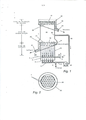
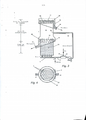
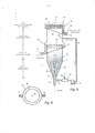
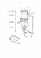
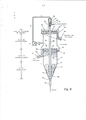
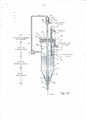
A invenção será descrita agora com referência às figuras anexas, nas quais: a Figura 1 é uma elevação em seção transversal esquemática de um dispositivo de flotação de acordo com a invenção, a Figura 2 é uma vista de planta em seção transversal da linha A-A da Figura 1, a Figura 3 é uma elevação em seção transversal esquemática similar à Figura 1, incluindo uma corrente de reciclagem aerada, a Figura 4 é uma vista de planta em seção transversal da Figura 3, similar à Figura 2, a Figura 5 é uma elevação em seção transversal esquemática similar à Figura 1, mas incorporando um leito esguichado, a Figura 6 é uma vista de planta em seção transversal da Figura 5, similar à Figura 2, • a Figura 7 é uma elevação em seção transversal esquemática similar à Figura 5, mas incorporando um leito esguichado com um tubo de extração a Figura 8 é uma vista de planta em seção transversal da Figura 7, similar à Figura 2, a Figura 9 é uma elevação em seção transversal esquemática, similar à Figura 5, mas mostrando uma realização que inclui um tubo descendente para introduzir o líquido de reciclagem na base de um leito esguichado, e a Figura 10 é uma elevação em seção transversal esquemática, similar à Figura 9, que mostra um leito fluidizado esguichado em contato com o dispositivo de acordo com a invenção que incorpora uma bomba de elevação a ar para o controle de nível.The invention will now be described with reference to the attached figures, in which: Figure 1 is a schematic cross-sectional elevation of a flotation device according to the invention, Figure 2 is a plan view in cross section of line AA of the Figure 1, Figure 3 is an elevation in schematic cross section similar to Figure 1, including an aerated recycling stream, Figure 4 is a plan view in cross section of Figure 3, similar to Figure 2, Figure 5 is a elevation in schematic cross section similar to Figure 1, but incorporating a squirted bed, Figure 6 is a plan view in cross section of Figure 5, similar to Figure 2, • Figure 7 is an elevation in schematic cross section similar to Figure 5, but incorporating a squirted bed with an extraction tube, Figure 8 is a plan view in cross section of Figure 7, similar to Figure 2, Figure 9 is a schematic cross section elevation, similar to Figure 5, but m showing an embodiment that includes a descending tube to introduce the recycling liquid at the base of a squirted bed, and Figure 10 is a schematic cross section elevation, similar to Figure 9, showing a fluidized bed squirted in contact with the according to the invention that incorporates an air lift pump for level control.
As Figuras 1 e 2 mostram elevação em seção transversal e uma vista de planta, respectivamente, de uma primeira realização preferida de acordo com a invenção. A carga líquida que contém as partículas a ser separadas pela flotação é preparada e condicionada com os reagentes de coletor e de espuma apropriados antes da entrada no vaso ou na coluna I. Para conveniência, é suposto que o vaso é uma coluna com simetria rotatória em torno do eixo geométrico vertical. A base da coluna é uma seção cilíndrica vertical 13, no alto da qual é disposta uma calha interna 14. A carga da coluna entra na entrada 2, onde se mistura com um suprimento de líquido de reciclagem que entra do duto 11. As duas correntes se combinam e entram em um sistema de distribuição 3 que alimenta várias tubulações de entrada 4 na base da célula de flotação. A vazão de água total é tal que a velocidade superficial da água na célula excede o valor mínimo necessário para a fluidização. O ar é introduzido na célula através de um duto 5, do qual passa para um distribuidor 6, do qual se divide para entrar no leito fluidizado através de várias tubulações verticais pequenas 7. Na extremidade superior das tubulações as correntes de ar formam pequenas bolhas que se desprendem e se elevam no leito fluidizado.Figures 1 and 2 show elevation in cross section and a plan view, respectively, of a first preferred embodiment according to the invention. The liquid charge containing the particles to be separated by flotation is prepared and conditioned with the appropriate collector and foam reagents before entering the vessel or column I. For convenience, the vessel is assumed to be a column with rotational symmetry in around the vertical geometric axis. The base of the column is a vertical
No leito fluidizado as partículas são separadas umas das outras e suportadas pelo líquido ascendente, embora 10 a fração do volume de água não seja elevada, sendo da ordem de 0,5 a 0,6. O espaço entre as partículas é de fato geralmente menor do que os diâmetros das bolhas introduzidas através das tubulações de entrada 7, de modo que à medida que as bolhas se elevam no leito fluidizado elas empurram as 15 partículas para um lado e são colocadas em contato íntimo com as mesmas. Se as partículas forem hidrofóbicas há uma grande probabilidade de elas serem capturadas pelas bolhas, ao passo que as partículas hidrofílicas não são coletadas. No alto da coluna 13, uma interface 19 é formada entre o leito 20 fluidizado e o líquido acima. As partículas 22 que não se unem às bolhas fluem sobre a boca interna 20 e são removidas do vaso através da tubulação de descarga de refugos 21. As bolhas que se elevam para fora do leito fluidizado 18 passam por uma zona relativamente plácida 30, carregando com elas 25 algumas partículas hidrofóbicas que coletaram no leito. A zona 30 age como uma zona de sedimentação em que as partículas de ganga que podem ter sido arrastadas pelas bolhas que se elevaram para fora do leito fluidizado podem, devido à gravidade, retornar ao alto do leito 19. As bolhas 3 0 com partículas hidrofóbicas unidas se elevam para o alto da coluna, passando pela camada de espuma 31 que é formada aqui. A espuma flui sobre a boca superior 32 da célula de flotação, para uma calha 3 3 que é descarregada através de um duto 34 como produto da flotação. A profundidade da camada de espuma 31 -é mantida em um nível apropriado ao controlar a interface 35 por meios que não são mostrados.In the fluidized bed the particles are separated from each other and supported by the ascending liquid, although 10 the fraction of the volume of water is not high, being in the order of 0.5 to 0.6. The space between the particles is in fact generally smaller than the diameters of the bubbles introduced through the inlet pipes 7, so that as the bubbles rise in the fluidized bed they push the 15 particles to one side and are brought into contact intimate with them. If the particles are hydrophobic there is a high probability that they will be captured by the bubbles, whereas the hydrophilic particles are not collected. At the top of
Para manter o leito fluidizado 18, é necessário que 5 a vazão de água que entra através das tubulações de distribuição 4 seja sempre suficiente para manter a velocidade superficial da água no leito acima da velocidade de fluidização mínima. Devido a razões práticas, isso nem sempre pode ser possível ao se confiar unicamente na água 10 contida na carga fresca de entrada 2. Por exemplo, se houver uma unidade de recalque a montante da célula de flotação, o fluxo da carga nova pode cessar completamente, ou a fração de água na carga pode variar consideravelmente. Para superar este problema, é provida uma corrente de reciclagem de 15 líquido. Uma corrente de líquido da zona de sedimentação 30 acima do leito fluidizado é extraída através de uma abertura 39 na parede do vaso para uma tubulação 40 pela bomba 41. A corrente de reciclagem entra através da ramificação da tubulação 11 onde se mistura com a carga nova que entra 2 0 através do duto 2, e continua até o distribuidor 3 e as tubulações de distribuição 4. Uma vez que o líquido de reciclagem é extraído da zona de sedimentação acima do leito fluidizado, ele é predominantemente água.To maintain the
Deve ser considerado que as bolhas de ar podem ser 25 introduzidas em um leito fluidizado de partículas através de um pulverizador poroso, ou carregadas para a corrente de carga antes da descarga no leito. No entanto, o uso da corrente de reciclagem confere flexibilidade extra à operação do leito fluidizado, em que a vazão do líquido de fluidização 30 é essencialmente independente da vazão do líquido de carga na célula.It should be considered that air bubbles can be introduced into a fluidized bed of particles through a porous spray, or loaded into the loading stream prior to discharge into the bed. However, the use of the recycling stream gives extra flexibility to the operation of the fluidized bed, in which the flow of the fluidizing
Uma desvantagem das pequenas tubulações 7 que são utilizadas para distribuir o ar no leito fluidizado é que para formar bolhas pequenas o diâmetro interno dessas tubulações deve ser muito pequeno, da ordem de um milímetro ou menos, para formar bolhas pequenas. As tubulações de dimensões tão pequenas são predispostas a bloqueios por 5 partículas ou por produtos da corrosão, e seria vantajoso se fosse provido um dispositivo alternativo não tão predisposto a bloqueios. Em uma realização alternativa mostrada na Figura 3 e na Figura 4, a corrente de reciclagem passa através de um aerador apropriado 42 onde se mistura com um suprimento de ar 10 controlado que entra através da porta 43. O aerador 42 pode conter convenientemente um aspersor ou dispositivo de misturação em linha para dispersar o suprimento de ar no líquido na forma de pequenas bolhas de tamanho conveniente para a flotação, antes da injeção na base da coluna através 15 da ramificação da tubulação 11. Alternativamente, as bolhas de ar poderiam ser espargidas na corrente de carga, ou diretamente no próprio leito, mas é mais vantajoso inserir o ar na linha de reciclagem, cuja vazão pode ser controlada independentemente das condições no leito fluidizado.A disadvantage of the small pipes 7 which are used to distribute the air in the fluidized bed is that to form small bubbles the internal diameter of these pipes must be very small, on the order of a millimeter or less, to form small bubbles. Pipes of such small dimensions are predisposed to blockages by 5 particles or corrosion products, and it would be advantageous if an alternative device not so predisposed to blockages would be provided. In an alternative embodiment shown in Figure 3 and Figure 4, the recycling stream passes through an
Em uma realização alternativa tal como aquela mostrada nas Figuras 5 e 6, a carga líquida é condicionada com reagentes de coletor e de espuma apropriados antes da entrada no vaso ou na coluna I. Para fins de conveniência, será suposto que a coluna é um vaso com simetria rotatória em 25 torno do eixo geométrico vertical. A base da coluna tem a forma de um cone invertido 12, unido a uma seção cilíndrica vertical 13, no alto da qual fica localizada uma calha interna 14. A carga da coluna entra na entrada 10, onde se mistura com um suprimento de líquido de reciclagem aerado que 3 0 entra de um duto 11. As duas correntes escoam essencialmente em uma direção vertical na coluna, movendo-se em combinação a uma velocidade suficiente para formar um leito fluidizado esguichado 15 no cone invertido 12. As partículas e as bolhas fluem para cima no centro do leito, e o momentum difunde as mesmas gradual e radialmente para fora. Um fluxo de circulação padrão é desenvolvido, no qual as partículas do leito fluidizado são arrastadas no jato de carga na região de 5 entrada 16 ou próximo dela. Elas se elevam, carregadas pela energia do jato. À medida que o jato se eleva no cone, o seu momentum é transferido gradualmente para as partículas e o líquido circundantes, e quando o jato alcança o alto do cone 17 à energia que entra é essencialmente distribuída de modo 10 uniforme através da seção transversal do leito fluidizado, e acima deste ponto é formado um leito fluidizado uniforme 18. As partículas que entraram na base do leito esguichado em 16 são substituídas por outras partículas das camadas superiores na célula, que deslizam para baixo na parede interna do cone 15 12 para a região de entrada 15.In an alternative embodiment such as that shown in Figures 5 and 6, the liquid charge is conditioned with appropriate collector and foam reagents prior to entry into the vessel or column I. For convenience, the column will be assumed to be a vessel with rotational symmetry around 25 vertical vertical axis. The base of the column is in the form of an
Na zona de sedimentação acima do cone, todos os rompimentos turbulentos que podem ter sido associados com o leito esguichado são dispersos, e o leito tem uma influência suavizante no fluxo. No alto da coluna de lados paralelos 13, 20 uma interface 19 é formada entre o leito fluidizado e o líquido acima. As partículas que não se unem às bolhas fluem sobre a boca interna 20 e são removidas do vaso através da tubulação de descarga de refugos 21. As bolhas que se elevam do leito fluidizado 18 passam para uma zona relativamente 25 plácida 30, carregando com elas algumas partículas hidrofóbicas que coletaram no leito. Nesta zona, as partículas de ganga que podem ter sido arrastadas pelas bolhas que se elevaram para fora do leito fluidizado podem, devido à gravidade, recuar para o alto do leito 19. As bolhas 30 com partículas hidrofóbicas unidas se elevam para o alto da coluna, passando pela camada de espuma 31 que é aqui formada. A espuma flui sobre a boca superior 32 da célula de flotação, para uma calha 3 3 que é descarregada através de um duto 34 como produto da flotação. A profundidade da camada de espuma 31 'é mantida em um nível apropriado ao controlar a interface 35 por meios que não são mostrados.In the sedimentation zone above the cone, all the turbulent ruptures that may have been associated with the squirted bed are dispersed, and the bed has a smoothing influence on the flow. At the top of the parallel-
Para manter o leito fluidizado 18 acima da velocidade de fluidização mínima, uma corrente de líquido da zona de sedimentação 30 acima do leito fluidizado é extraída através de uma abertura 3 9 na parede do vaso para uma tubulação 40 pela bomba 41, passando através de um aerador apropriado 42 onde se mistura com um suprimento controlado de ar pressurizado que entra através da porta 43. O aerador 42 pode conter convenientemente um aspersor ou dispositivo de misturação em linha para dispersar o suprimento de ar no líquido na forma de bolhas pequenas de um tamanho conveniente para a flotação, antes da injeção na base da coluna através da tubulação 11. Alternativamente, as bolhas de ar poderiam ser espargidas na corrente de carga, ou diretamente no próprio leito, mas é mais vantajoso inserir o ar na linha de reciclagem, cuja vazão pode ser controlada independentemente das condições no leito fluidizado.To keep the
Outra realização da invenção é mostrada na elevação em seção transversal da Figura 7 e na vista de planta em seção transversal da Figura 8. Nesta realização, um tubo de extração 50 é montado na parte cônica da coluna de flotação mostrada na Figura 5 para fornecer a estabilidade direcional ao jato que jorra. Em alguns casos é observado que o jato é instável e pode se mover para um lado ou outro dentro da coluna. A provisão de um tubo de extração assegura que o fluxo em ascensão guiado pelo momentum do jato de entrada e também pelo poder de flutuação das bolhas que se elevam com o fluxo seja controlado e compelido a se elevar ao longo do eixo da coluna.Another embodiment of the invention is shown in the elevation in cross section of Figure 7 and in the plan view in cross section of Figure 8. In this embodiment, an
Uma outra realização da invenção é mostrada na Figura 9. Um leito fluidizado esguichado é formado na coluna 1 tal como mostrado anteriormente na Figura 5. Uma corrente de ‘reciclagem da zona de sedimentação 3 0 acima do leito fluidizado é extraída através de uma abertura 39 na parede do vaso para uma tubulação 4 0 pela bomba 41, passando para o 5 topo de um tubo descendente 60. O tubo descendente mostrado na Figura 9 consiste em um duto que é essencialmente vertical, posicionado coaxialmente com a coluna de flotação I. No alto do tubo descendente, a carga é forçada através de um bocal 61 para formar um jato vertical de alta velocidade 10 do líquido 62 que entra em uma câmara 63 onde encontra um fluxo de ar ou um outro gás apropriado que entra através de uma porta 64 e se mistura com o mesmo. No tubo descendente, as partículas que flutuam na corrente de reciclagem são colocadas em contato íntimo com as bolhas de ar finas criadas 15 pela ação de corte do jato penetrante, e as partículas hidrofóbicas se unem às bolhas. A mistura das bolhas e da pasta de carga se move para baixo através do tubo descendente 60, desembocando em sua extremidade inferior 64 na base do leito esguichado 16, onde se mistura com a pasta de carga que 20 entra na entrada 10. 0 fluxo combinado da pasta e das bolhas de ar então se eleva, criando e mantendo o leito esguichado 15. A relação entre a vazão volumétrica do ar e a vazão da pasta de reciclagem fica tipicamente compreendida na faixa de 0,1 a 5, e mais especificamente de 0,5 a 2, calculada à 25 pressão atmosférica.Another embodiment of the invention is shown in Figure 9. A squirted fluidized bed is formed in
Uma vantagem do tubo descendente vertical 60 é que é menos provável que as partículas graúdas de minério possam se sedimentar e se acumular dentro do mesmo. Quando o líquido contiver partículas grandes que se sedimentam rapidamente, os 30 dispositivos de aeração tais como aqueles mostrados na Figura 5 podem ficar propensos ao bloqueio ou à sedimentação no duto horizontal 11 que conduz à base do leito esguichado 16, um efeito que é exacerbado na presença de bolhas de ar. Deve ser considerado que outras formas de tubo descendente do tubo de aeração são conhecidas e podem ser utilizadas no lugar do tubo descendente aqui mostrado, uma vez que o duto que fornece a corrente líquida aerada à base do leito esguichado seja essencialmente vertical.An advantage of the
Nas realizações mostradas nas Figuras 1, 3, 5, 7 e 9, os refugos fluidizados fluem sobre uma boca interna 20 e para a calha 14. A posição da boca 20 define essencialmente a extensão superior do leito fluidizado. No entanto, tal como mostrado nas figuras, a posição da boca 20 é fixa e não pode ser facilmente alterada. Um método alternativo de retirar os refugos e de manter o leito em uma altura fixa, que é aplicável a algumas das realizações mostradas nas figuras acima, é mostrado na Figura 10 a título de exemplo. Uma bomba de elevação a ar é utilizada para extrair os refugos fluidizados do leito. Ela consiste em um duto vertical 70 em que uma corrente de ar de baixa pressão é impelida para uma porta conveniente 71. Quando o ar entra no duto 70, ele se dispersa nas bolhas 77 que se elevam devido à gravidade. Por causa da diferença na densidade entre a pasta na zona de sedimentação 30 e a corrente aerada dentro do duto ascendente 70, um fluxo que força os refugos para cima no tubo ascendente é estabelecido. A densidade média do leito fluidizado que tem um elevado teor de sólidos é maior do que aquela do líquido na zona de sedimentação 30. A interface 19 apresenta similaridades com a superfície de um corpo de água exposto à atmosfera. Desse modo, a pasta fluidizada flui na direção da base 72 do duto ascendente 70, mantendo desse modo a altura do leito fluidizado em um nível particular. A pasta arrastada pelas bolhas de ar no tubo ascendente 70 flutua sobre a boca 73 e sai do vaso como uma corrente de refugos 74. As bolhas de ar se separam da corrente da pasta e escapam através da ramificação superior 75. A bomba de elevação a ar tem diversas vantagens, é simples de construir e de operar e não‘ é propensa a bloqueios por partículas grandes de refugos. O fluxo de ar é ajustado em relação à área do duto, de modo a manter o fluxo dos refugos a uma taxa determinada. Um 5 controlador de fluxo (não mostrado) que responde a um sinal de um dispositivo apropriado que detecta a posição da superfície superior do leito fluidizado pode ser ajustado à linha de suprimento de ar 76. Desse modo, um sistema de controle automático pode ser instalado a fim de manter a 10 altura do leito fluidizado em um nível determinado, ao variar a vazão do ar, conforme necessário. Deve ser considerado que outros dispositivos com exceção da bomba de elevação a ar podem ser utilizados para extrair a pasta de refugos do leito fluidizado. No entanto, dispositivos tais como uma bomba de 15 pasta não tem as características inerentes de uma bomba de elevação a ar, tais como a simplicidade de operação e manutenção e a resistência a bloqueio por partículas graúdas.In the embodiments shown in Figures 1, 3, 5, 7 and 9, fluidized waste flows over an
Uma característica importante de todas as realizações da invenção é a criação da zona de sedimentação 20 18, que age para eliminar a turbulência que poderia, de outra maneira, fazer com que os agregados bolha-partícula se decomponham ao se elevar na zona de sedimentação 30. Ao operar o leito com velocidades de fluidização que só estejam ligeiramente acima da velocidade mínima de fluidização, os 25 canais no leito ficam muito pequenos, da mesma ordem da magnitude do diâmetro das partículas no leito. Consequentemente, o número de Reynolds, que é um indicador dos níveis de turbulência em um fluido, é muito pequeno. O ambiente de baixa turbulência acima do leito fluidizado é 30 muito favorável ao transporte de partículas graúdas do leito para a zona de espuma 31.An important feature of all the embodiments of the invention is the creation of the
O uso do fluido de reciclagem como fonte de água para fluidização é uma vantagem importante da invenção. Se o único líquido disponível para fluidizar as partículas sólidas for' a água da carga, não será possível efetuar a operação estável da coluna, a menos que a vazão da carga e a concentração de sólidos na carga sejam constantes. O uso da 5 corrente de reciclagem desfaz a conexão com o líquido da carga. A vazão da corrente de reciclagem é independente da vazão da carga, portanto, se o fluxo da coluna for interrompido, por exemplo, por um mau funcionamento da unidade, os sólidos no leito ainda podem ser mantidos em um 10 estado fluidizado até a reinicialização da unidade, ao manter o fluxo na corrente de reciclagem.The use of recycling fluid as a source of water for fluidization is an important advantage of the invention. If the only liquid available to fluidize the solid particles is the water in the load, it will not be possible to perform the stable operation of the column, unless the flow rate of the load and the concentration of solids in the load are constant. The use of the
Nas realizações da invenção mostradas nas figuras, a corrente de refugos, que contém as partículas não hidrofóbicas ou hidrofílicas, é extraída do alto do leito 15 fluidizado. Isto é feito para fins de conveniência, porque os dispositivos para a remoção dos refugos - a boca de transbordamento 20 ou a extremidade inferior 70 da bomba de elevação a ar - também servem para determinar a altura do leito fluidizado. No entanto, é possível remover os refugos 20 de uma posição dentro do leito fluidizado ao propiciar um sistema de controle por instrumentos que consiste em dispositivos tais como um flutuador para detectar a posição da interface 19 entre o leito fluidizado e a zona de sedimentação; e dispositivos para variar ou controlar a vazão 25 dos refugos da célula de flotação em resposta aos sinais do dispositivo para detecção do nível da interface para manter o topo do leito fluidizado em um nível desejado.In the embodiments of the invention shown in the figures, the waste stream, which contains the non-hydrophobic or hydrophilic particles, is extracted from the top of the
O fato de o contato ser feito em um leito fluidizado tem implicações importantes para a concentração de 30 sólidos na carga. No ponto de fluidização incipiente, a fração de volume dos sólidos em um leito de partículas granulosas é tipicamente 0,6, de modo que se a densidade dos sólidos for de 2.800 kg/m3, que é a densidade dos minerais de ganga silícicos encontrados frequentemente nos minérios, a concentração de sólidos em uma base em peso será de 8 0 por cento em peso/peso, e a massa de água por unidade de massa dos sólidos pode ser calculada como sendo 4,2 toneladas de 5 sólidos por tonelada de água. Quando a velocidade da água é aumentada acima do mínimo necessário para fluidização, a fração do volume de sólidos diminui, mas um valor típico em um leito fluidizado é 0,5, que corresponde a 2,8 toneladas de sólidos por tonelada de água. Para a flotação em máquinas 10 convencionais, a carga geralmente é preparada com uma fração de sólidos de 35 por cento em peso/peso, para a qual a fração de volume é 0,54, e a massa dos sólidos por unidade de massa de água é de 0,538 tonelada de sólidos por tonelada de água. Tais frações de sólidos baixos são necessárias por causa da 15 dificuldade de processamento de cargas com fração de volume elevada nas tecnologias de flotação conhecidas. No entanto, em um leito fluidizado não há nenhum problema em preparar a carga com percentual de sólidos baixo, pois as próprias propriedades do leito garantem que a fração de sólidos 20 aumente, por causa do deslizamento entre as partículas e o fluido. Desse modo, o teor de sólidos na carga da célula de flotação pode ser aumentado para o mesmo valor da fração de sólidos no próprio leito. Neste caso, a água necessária para a carga deve ser menor do que um fator de 2.800/0,538 ou 5,2. Desse modo, a água necessária para a flotação deve ser reduzida até aproximadamente apenas um quinto da água necessária nas máquinas de flotação convencionais. Esta é uma economia muito significativa, especialmente nas áreas geográficas em que a água é escassa.The fact that the contact is made in a fluidized bed has important implications for the concentration of 30 solids in the load. At the incipient fluidization point, the volume fraction of the solids in a bed of granular particles is typically 0.6, so that if the density of the solids is 2,800 kg / m3, which is the density of silicic gangue minerals frequently found in ores, the concentration of solids on a weight basis will be 80 percent by weight / weight, and the mass of water per unit mass of the solids can be calculated to be 4.2 tons of 5 solids per ton of water . When the water velocity is increased above the minimum required for fluidization, the fraction of the volume of solids decreases, but a typical value in a fluidized bed is 0.5, which corresponds to 2.8 tons of solids per ton of water. For flotation on conventional machines, the charge is usually prepared with a solids fraction of 35 weight / weight percent, for which the volume fraction is 0.54, and the mass of solids per unit mass of water. is 0.538 ton of solids per ton of water. Such low solids fractions are necessary because of the difficulty of processing loads with a high volume fraction in known flotation technologies. However, in a fluidized bed there is no problem in preparing the load with a low percentage of solids, since the properties of the bed itself ensure that the fraction of
Dessa maneira, a presente invenção pode apresentar um processo de flotação de espuma aprimorado em que a flotação é executada em um leito fluidizado. A faixa de tamanho das partículas que podem ser capturadas na flotação pode ser ampliada por uma ordem de magnitude comparada com as tecnologias atuais enquanto mantém uma alta eficiência na captação em relação a toda a faixa de tamanho de partículas na carga. A invenção também pode apresentar um processo de 5 flotação que conduza a uma redução no consumo de água na flotação.In this way, the present invention can present an improved foam flotation process in which the flotation is performed in a fluidized bed. The particle size range that can be captured in flotation can be increased by an order of magnitude compared to current technologies while maintaining high capture efficiency over the entire particle size range in the charge. The invention can also have a flotation process that leads to a reduction in water consumption in flotation.
A invenção deriva de uma estimativa de que os altos níveis de turbulência criados nas tecnologias de flotação anteriores conduzam a uma redução na eficiência das 10 partículas graúdas pela flotação. Para reduzir os níveis de turbulência, é provido um ambiente de flotação em que as partículas são capturadas por bolhas em um fluxo laminar em um leito fluidizado. A carga da flotação se eleva através do leito, que é suficientemente profundo para impedir quaisquer 15 redemoinhos turbulentos que possam ter sido introduzidos na célula de flotação com a pasta de carga que é inserida.The invention derives from an estimate that the high levels of turbulence created in previous flotation technologies lead to a reduction in the efficiency of the 10 large particles by flotation. To reduce the levels of turbulence, a flotation environment is provided in which the particles are captured by bubbles in a laminar flow in a fluidized bed. The flotation charge rises through the bed, which is deep enough to prevent any 15 turbulent swirls that may have been introduced into the flotation cell with the load paste that is inserted.
Uma característica da invenção é que o campo de fluxo no leito fluidizado é muito plácido, e a turbulência que está presente em todas as tecnologias anteriores é 20 eliminada. As condições de fluxo no leito fluidizado são altamente propensas à formação de excedentes estáveis entre as bolhas e as partículas graúdas. As bolhas que carregam as partículas a ser separadas se elevam por uma zona de sedimentação onde as partículas não desejadas e agregadas 25 possam se separar e retornar ao leito fluidizado. A carga do processo pode apresentar um teor de sólidos muito mais elevados do que os processos previamente conhecidos.A feature of the invention is that the flow field in the fluidized bed is very placid, and the turbulence that is present in all prior technologies is eliminated. The flow conditions in the fluidized bed are highly prone to the formation of stable surpluses between bubbles and coarse particles. The bubbles that carry the particles to be separated rise through a sedimentation zone where the unwanted and aggregated particles 25 can separate and return to the fluidized bed. The process load can have a much higher solids content than previously known processes.
Uma outra característica da invenção é que uma corrente de reciclagem é retirada da zona de sedimentação na 30 célula de flotação acima do leito fluidizado e retorna à base do leito fluidizado como dispositivo para manter a velocidade superficial da água no leito acima do mínimo necessário para fluidização.Another feature of the invention is that a recycling stream is removed from the sedimentation zone in the flotation cell above the fluidized bed and returned to the base of the fluidized bed as a device to maintain the surface speed of the water in the bed above the minimum required for fluidization. .
O método e o aparelho da presente invenção apresentam diversas vantagens, incluindo a capacidade de melhorar a recuperação por flotação das partículas de tamanho médio e das partículas de tamanhos relativamente grandes, 5 quando comparados com os métodos e os aparelhos da técnica anterior. Além disso, o processo pode operar a concentrações de sólidos muito mais elevados do que as tecnologias anteriores, conduzindo a economias significativas na água necessária para preparar a carga para a flotação.The method and apparatus of the present invention have several advantages, including the ability to improve the flotation recovery of medium-sized particles and relatively large-sized particles, 5 compared to prior art methods and apparatus. In addition, the process can operate at much higher solids concentrations than previous technologies, leading to significant savings in the water needed to prepare the charge for flotation.
Claims (5)
Priority Applications (1)
| Application Number | Priority Date | Filing Date | Title |
|---|---|---|---|
| BR122019017647-7A BR122019017647B1 (en) | 2007-02-26 | 2008-02-26 | APPLIANCE TO SEPARATE HYDROPHOBIC PARTICLES |
Applications Claiming Priority (3)
| Application Number | Priority Date | Filing Date | Title |
|---|---|---|---|
| AU2007900962 | 2007-02-26 | ||
| AU2007900962A AU2007900962A0 (en) | 2007-02-26 | Method and apparatus for flotation in a fluidized bed | |
| PCT/AU2008/000252 WO2008104022A1 (en) | 2007-02-26 | 2008-02-26 | Method and apparatus for flotation in a fluidized bed |
Publications (2)
| Publication Number | Publication Date |
|---|---|
| BRPI0807331A2 BRPI0807331A2 (en) | 2019-03-06 |
| BRPI0807331B1 true BRPI0807331B1 (en) | 2020-10-06 |
Family
ID=39720788
Family Applications (2)
| Application Number | Title | Priority Date | Filing Date |
|---|---|---|---|
| BRPI0807331-7A BRPI0807331B1 (en) | 2007-02-26 | 2008-02-26 | PARTICLE SEPARATION METHOD |
| BR122019017647-7A BR122019017647B1 (en) | 2007-02-26 | 2008-02-26 | APPLIANCE TO SEPARATE HYDROPHOBIC PARTICLES |
Family Applications After (1)
| Application Number | Title | Priority Date | Filing Date |
|---|---|---|---|
| BR122019017647-7A BR122019017647B1 (en) | 2007-02-26 | 2008-02-26 | APPLIANCE TO SEPARATE HYDROPHOBIC PARTICLES |
Country Status (8)
| Country | Link |
|---|---|
| US (2) | US9085000B2 (en) |
| AU (1) | AU2008221231B2 (en) |
| BR (2) | BRPI0807331B1 (en) |
| CA (1) | CA2677887C (en) |
| FI (1) | FI122471B (en) |
| MX (1) | MX2009009100A (en) |
| WO (1) | WO2008104022A1 (en) |
| ZA (1) | ZA200906645B (en) |
Families Citing this family (28)
| Publication number | Priority date | Publication date | Assignee | Title |
|---|---|---|---|---|
| WO2009026612A1 (en) * | 2007-08-28 | 2009-03-05 | Xstrata Technology Pty Ltd | Method for improving flotation cell performance |
| WO2010135760A1 (en) * | 2009-05-26 | 2010-12-02 | Newcastle Innovation Limited | Improved method and apparatus for froth flotation in a vessel with agitation |
| US8551330B2 (en) * | 2009-06-26 | 2013-10-08 | Westech Engineering, Inc. | Carbon retention screen with variable discharge head |
| DE202010009140U1 (en) * | 2010-06-16 | 2010-10-21 | Juan Valdivia Gmbh | Arrangement for generating air bubbles in liquids |
| CN102327818B (en) * | 2011-09-30 | 2013-12-25 | 湖南长高矿山机电设备有限公司 | Floatation device |
| US20230041631A1 (en) * | 2012-02-28 | 2023-02-09 | Cidra Corporate Services Llc | Method and system for flotation separation in a magnetically controllable and steerable medium |
| US9327251B2 (en) * | 2013-01-29 | 2016-05-03 | Lanzatech New Zealand Limited | System and method for improved gas dissolution |
| US9278360B2 (en) | 2013-10-17 | 2016-03-08 | Eriez Manufacturing Co. | Air-assisted separation system |
| US9718065B1 (en) * | 2014-02-28 | 2017-08-01 | Tetragrow, Llc | Method of plant resin separation and extraction |
| WO2016019411A1 (en) * | 2014-08-06 | 2016-02-11 | Newcastle Innovation Limited | An apparatus and method for removing an underflow stream |
| US10828648B2 (en) * | 2015-03-16 | 2020-11-10 | Johannes Gideon Andries Swanepoel | Flotation cell |
| CN104801429A (en) * | 2015-04-03 | 2015-07-29 | 河南理工大学 | Combined type column floating selection system |
| US10441958B2 (en) * | 2015-08-28 | 2019-10-15 | Hunter Process Technologies Pty Limited | System, method and apparatus for froth flotation |
| CN106944264B (en) * | 2017-05-10 | 2023-06-06 | 中国矿业大学 | Turbulence-regulated external particle fluidized bed mineralization flotation equipment with uniform turbulence |
| US11202983B2 (en) * | 2017-11-08 | 2021-12-21 | Btu International, Inc. | Devices, systems and methods for flux removal from furnace process gas |
| CN108970813B (en) * | 2018-10-24 | 2020-04-07 | 中南大学 | Fluidized coarse grain flotation equipment and flotation method |
| CN110153143A (en) * | 2019-03-14 | 2019-08-23 | 西安煤科动力科技有限公司 | A kind of coal slime tailing, fired brick prepared therefrom and preparation method thereof |
| WO2021019122A1 (en) * | 2019-07-29 | 2021-02-04 | Outotec (Finland) Oy | Flotation cell |
| US20220258179A1 (en) * | 2019-07-29 | 2022-08-18 | Metso Outotec Finland Oy | Flotation cell |
| WO2021084155A1 (en) * | 2019-10-28 | 2021-05-06 | Outotec (Finland) Oy | Method for process water treatment |
| CN113318866B (en) * | 2021-06-01 | 2023-02-10 | 合肥皖燃新材料科技有限公司 | Aeration type flotation machine for processing high-white superfine magnesium hydroxide fire retardant by physical method |
| CN114700182B (en) * | 2021-07-22 | 2023-07-14 | 中国矿业大学 | Coarse particle fluidized flotation device and method with gradient air intake |
| US11898134B2 (en) | 2021-11-03 | 2024-02-13 | Lanzatech, Inc. | Reactor having dynamic sparger |
| US12091648B2 (en) | 2021-11-03 | 2024-09-17 | Lanzatech, Inc. | System and method for generating bubbles in a vessel |
| US20250128272A1 (en) * | 2023-10-19 | 2025-04-24 | Metso Finland Oy | Flotation unit and flotation method |
| CN118635010B (en) * | 2024-08-13 | 2024-11-19 | 临沂市蓝晶光电科技有限公司 | Flotation machine for quartz sand purification |
| CN119076237B (en) * | 2024-09-09 | 2026-04-24 | 中国矿业大学 | Fluidized bed flotation device and method for coarse-grain mineral separation and recovery |
| CN119237142B (en) * | 2024-10-12 | 2025-10-17 | 中国矿业大学 | Coarse particle fluidized bed column separation dynamics analysis device and method |
Family Cites Families (21)
| Publication number | Priority date | Publication date | Assignee | Title |
|---|---|---|---|---|
| US1973278A (en) * | 1929-04-10 | 1934-09-11 | United Verde Copper Company | Froth control in ore flotation |
| US2226170A (en) * | 1938-01-13 | 1940-12-24 | Philadelphia And Reading Coal | Flotation of materials |
| US2783884A (en) * | 1950-12-06 | 1957-03-05 | Ruhrchemie Ag | Process and apparatus for the contacting of granular materials with liquids and gases |
| US2778499A (en) * | 1952-09-16 | 1957-01-22 | Coal Industry Patents Ltd | Method of froth flotation |
| US4472271A (en) | 1982-08-25 | 1984-09-18 | Freeport Kaolin Company | Froth flotation apparatus and process |
| SU1282908A1 (en) | 1985-03-25 | 1987-01-15 | Производственное Объединение "Ворошиловградуглеобогащение" | Flotation machine |
| US4981582A (en) * | 1988-01-27 | 1991-01-01 | Virginia Tech Intellectual Properties, Inc. | Process and apparatus for separating fine particles by microbubble flotation together with a process and apparatus for generation of microbubbles |
| US5167798A (en) | 1988-01-27 | 1992-12-01 | Virginia Tech Intellectual Properties, Inc. | Apparatus and process for the separation of hydrophobic and hydrophilic particles using microbubble column flotation together with a process and apparatus for generation of microbubbles |
| US4960509A (en) | 1989-07-17 | 1990-10-02 | Colorado School Of Mines | Ore flotation device and process |
| US5249688A (en) | 1990-03-12 | 1993-10-05 | Board Of Control Of Michigan Technological University | Froth flotation apparatus |
| ZA919256B (en) * | 1990-11-23 | 1992-11-25 | Atomaer Pty Ltd | Gas particle formation |
| US5431286A (en) * | 1994-01-06 | 1995-07-11 | Inco Limited | Recirculating column flotation apparatus |
| CA2140305A1 (en) | 1995-01-16 | 1996-07-17 | Turgut Yalcin | Method and apparatus for froth flotation |
| US5467876A (en) | 1995-04-04 | 1995-11-21 | The United States Of America As Represented By The Secretary Of The Interior | Method and apparatus for concentration of minerals by froth flotation |
| CA2171033C (en) | 1996-03-05 | 2009-07-14 | Tesfaye Negeri | Frothless flotation apparatus |
| US6082548A (en) * | 1996-09-13 | 2000-07-04 | Chemtech Analysis Inc. | Mobile soil treatment apparatus and method |
| US6425485B1 (en) * | 1998-03-26 | 2002-07-30 | Eriez Magnetics | Air-assisted density separator device and method |
| WO2001066259A2 (en) * | 2000-03-10 | 2001-09-13 | Aeromix Process Systems (Pty) Ltd | Apparatus and process for recovering a desired fraction of a raw material |
| NO20011231L (en) * | 2001-03-09 | 2002-09-10 | Norsk Hydro As | Method and apparatus for separating fractions in a material stream |
| US20040089595A1 (en) | 2002-11-13 | 2004-05-13 | Christian Kujawa | Flotation machine |
| ZA200704960B (en) | 2004-11-26 | 2009-06-24 | Univ Queensland | Improvements to a fluid jet flotation apparatus |
-
2008
- 2008-02-26 BR BRPI0807331-7A patent/BRPI0807331B1/en active IP Right Grant
- 2008-02-26 BR BR122019017647-7A patent/BR122019017647B1/en active IP Right Grant
- 2008-02-26 CA CA2677887A patent/CA2677887C/en active Active
- 2008-02-26 WO PCT/AU2008/000252 patent/WO2008104022A1/en not_active Ceased
- 2008-02-26 MX MX2009009100A patent/MX2009009100A/en active IP Right Grant
- 2008-02-26 US US12/528,531 patent/US9085000B2/en active Active
- 2008-02-26 AU AU2008221231A patent/AU2008221231B2/en active Active
-
2009
- 2009-09-23 ZA ZA2009/06645A patent/ZA200906645B/en unknown
- 2009-09-25 FI FI20095984A patent/FI122471B/en not_active IP Right Cessation
-
2015
- 2015-07-21 US US14/804,505 patent/US10040075B2/en active Active
Also Published As
| Publication number | Publication date |
|---|---|
| CA2677887C (en) | 2016-07-26 |
| US20150321202A1 (en) | 2015-11-12 |
| FI122471B (en) | 2012-02-15 |
| AU2008221231B2 (en) | 2012-07-12 |
| US10040075B2 (en) | 2018-08-07 |
| AU2008221231A1 (en) | 2008-09-04 |
| MX2009009100A (en) | 2010-02-17 |
| FI20095984L (en) | 2009-09-25 |
| BR122019017647B1 (en) | 2020-08-11 |
| CA2677887A1 (en) | 2008-09-04 |
| US20100193408A1 (en) | 2010-08-05 |
| BRPI0807331A2 (en) | 2019-03-06 |
| US9085000B2 (en) | 2015-07-21 |
| WO2008104022A1 (en) | 2008-09-04 |
| ZA200906645B (en) | 2018-11-28 |
Similar Documents
| Publication | Publication Date | Title |
|---|---|---|
| BRPI0807331B1 (en) | PARTICLE SEPARATION METHOD | |
| AU2023200768B2 (en) | System, method and apparatus for froth flotation | |
| US11981584B2 (en) | Method for separating low density particles from feed slurries | |
| US20120061298A1 (en) | Improved method and apparatus for froth flotation in a vessel with agitation | |
| CN103657839A (en) | Gas-liquid-solid three-phase fluidized bed sorting machine and sorting method thereof | |
| CA2938215C (en) | Flotation cell and system for separating hydrophobic particles from a mixture of particles and liquid | |
| CN113198622B (en) | A kind of microbubble secondary mineralization flotation equipment and flotation method | |
| CN110891689B (en) | Foam collection chute | |
| Galvin et al. | Gravity separation and flotation of fine particles using the Reflux Classifier platform | |
| EA051742B1 (en) | SYSTEM, METHOD AND DEVICE FOR FOAM FLOTATION | |
| CN113198621A (en) | Wide-size-fraction flotation equipment and flotation method | |
| BR112021001871B1 (en) | FLOTATION LINE |
Legal Events
| Date | Code | Title | Description |
|---|---|---|---|
| B06F | Objections, documents and/or translations needed after an examination request according [chapter 6.6 patent gazette] | ||
| B07A | Application suspended after technical examination (opinion) [chapter 7.1 patent gazette] | ||
| B06A | Patent application procedure suspended [chapter 6.1 patent gazette] | ||
| B09A | Decision: intention to grant [chapter 9.1 patent gazette] | ||
| B09X | Republication of the decision to grant [chapter 9.1.3 patent gazette] | ||
| B16A | Patent or certificate of addition of invention granted [chapter 16.1 patent gazette] |
Free format text: PRAZO DE VALIDADE: 10 (DEZ) ANOS CONTADOS A PARTIR DE 06/10/2020, OBSERVADAS AS CONDICOES LEGAIS. |