BRPI0706769B1 - device for making ice for a refrigerator - Google Patents
device for making ice for a refrigerator Download PDFInfo
- Publication number
- BRPI0706769B1 BRPI0706769B1 BRPI0706769-0A BRPI0706769A BRPI0706769B1 BR PI0706769 B1 BRPI0706769 B1 BR PI0706769B1 BR PI0706769 A BRPI0706769 A BR PI0706769A BR PI0706769 B1 BRPI0706769 B1 BR PI0706769B1
- Authority
- BR
- Brazil
- Prior art keywords
- ice
- making
- door
- tray
- water
- Prior art date
Links
- XLYOFNOQVPJJNP-UHFFFAOYSA-N water Substances O XLYOFNOQVPJJNP-UHFFFAOYSA-N 0.000 claims abstract description 229
- 238000003860 storage Methods 0.000 claims abstract description 49
- 238000009434 installation Methods 0.000 claims description 82
- 230000002265 prevention Effects 0.000 claims description 10
- 238000005520 cutting process Methods 0.000 claims description 8
- 230000001154 acute effect Effects 0.000 claims description 3
- 238000004519 manufacturing process Methods 0.000 claims description 3
- 239000000463 material Substances 0.000 claims description 3
- 238000003825 pressing Methods 0.000 claims description 3
- 239000008400 supply water Substances 0.000 claims description 2
- 206010044565 Tremor Diseases 0.000 claims 1
- 238000000034 method Methods 0.000 abstract description 10
- 238000011109 contamination Methods 0.000 abstract description 3
- 238000007710 freezing Methods 0.000 description 31
- 230000008014 freezing Effects 0.000 description 31
- 235000013305 food Nutrition 0.000 description 6
- 238000001816 cooling Methods 0.000 description 5
- 235000013311 vegetables Nutrition 0.000 description 3
- HCBIBCJNVBAKAB-UHFFFAOYSA-N Procaine hydrochloride Chemical compound Cl.CCN(CC)CCOC(=O)C1=CC=C(N)C=C1 HCBIBCJNVBAKAB-UHFFFAOYSA-N 0.000 description 1
- 230000004308 accommodation Effects 0.000 description 1
- 230000004075 alteration Effects 0.000 description 1
- 230000000694 effects Effects 0.000 description 1
- 238000005265 energy consumption Methods 0.000 description 1
- 238000012986 modification Methods 0.000 description 1
- 230000004048 modification Effects 0.000 description 1
- 210000002445 nipple Anatomy 0.000 description 1
- 238000005057 refrigeration Methods 0.000 description 1
Images


Classifications
-
- F—MECHANICAL ENGINEERING; LIGHTING; HEATING; WEAPONS; BLASTING
- F25—REFRIGERATION OR COOLING; COMBINED HEATING AND REFRIGERATION SYSTEMS; HEAT PUMP SYSTEMS; MANUFACTURE OR STORAGE OF ICE; LIQUEFACTION SOLIDIFICATION OF GASES
- F25C—PRODUCING, WORKING OR HANDLING ICE
- F25C5/00—Working or handling ice
- F25C5/20—Distributing ice
- F25C5/22—Distributing ice particularly adapted for household refrigerators
-
- F—MECHANICAL ENGINEERING; LIGHTING; HEATING; WEAPONS; BLASTING
- F25—REFRIGERATION OR COOLING; COMBINED HEATING AND REFRIGERATION SYSTEMS; HEAT PUMP SYSTEMS; MANUFACTURE OR STORAGE OF ICE; LIQUEFACTION SOLIDIFICATION OF GASES
- F25C—PRODUCING, WORKING OR HANDLING ICE
- F25C1/00—Producing ice
- F25C1/22—Construction of moulds; Filling devices for moulds
- F25C1/25—Filling devices for moulds
-
- F—MECHANICAL ENGINEERING; LIGHTING; HEATING; WEAPONS; BLASTING
- F25—REFRIGERATION OR COOLING; COMBINED HEATING AND REFRIGERATION SYSTEMS; HEAT PUMP SYSTEMS; MANUFACTURE OR STORAGE OF ICE; LIQUEFACTION SOLIDIFICATION OF GASES
- F25C—PRODUCING, WORKING OR HANDLING ICE
- F25C2305/00—Special arrangements or features for working or handling ice
- F25C2305/022—Harvesting ice including rotating or tilting or pivoting of a mould or tray
- F25C2305/0221—Harvesting ice including rotating or tilting or pivoting of a mould or tray rotating ice mould
-
- F—MECHANICAL ENGINEERING; LIGHTING; HEATING; WEAPONS; BLASTING
- F25—REFRIGERATION OR COOLING; COMBINED HEATING AND REFRIGERATION SYSTEMS; HEAT PUMP SYSTEMS; MANUFACTURE OR STORAGE OF ICE; LIQUEFACTION SOLIDIFICATION OF GASES
- F25C—PRODUCING, WORKING OR HANDLING ICE
- F25C2400/00—Auxiliary features or devices for producing, working or handling ice
- F25C2400/06—Multiple ice moulds or trays therefor
-
- F—MECHANICAL ENGINEERING; LIGHTING; HEATING; WEAPONS; BLASTING
- F25—REFRIGERATION OR COOLING; COMBINED HEATING AND REFRIGERATION SYSTEMS; HEAT PUMP SYSTEMS; MANUFACTURE OR STORAGE OF ICE; LIQUEFACTION SOLIDIFICATION OF GASES
- F25D—REFRIGERATORS; COLD ROOMS; ICE-BOXES; COOLING OR FREEZING APPARATUS NOT OTHERWISE PROVIDED FOR
- F25D23/00—General constructional features
- F25D23/02—Doors; Covers
- F25D23/04—Doors; Covers with special compartments, e.g. butter conditioners
-
- F—MECHANICAL ENGINEERING; LIGHTING; HEATING; WEAPONS; BLASTING
- F25—REFRIGERATION OR COOLING; COMBINED HEATING AND REFRIGERATION SYSTEMS; HEAT PUMP SYSTEMS; MANUFACTURE OR STORAGE OF ICE; LIQUEFACTION SOLIDIFICATION OF GASES
- F25D—REFRIGERATORS; COLD ROOMS; ICE-BOXES; COOLING OR FREEZING APPARATUS NOT OTHERWISE PROVIDED FOR
- F25D2323/00—General constructional features not provided for in other groups of this subclass
- F25D2323/122—General constructional features not provided for in other groups of this subclass the refrigerator is characterised by a water tank for the water/ice dispenser
Abstract
DISPOSITIVO PARA FABRICAR GELO PARA GELADEIRA A presente invenção refere-se a um dispositivo para fabricar gelo para uma geladeira. O dispositivo para fabricar gelo da presente invenção compreende um tanque de água instalado, de modo a poder destacar-se, sobre a superfície posterior da porta de uma geladeira para abrir ou fechar seletivamente um espaço de armazenamento, uma primeira e uma segunda bandejas para gelo instaladas, de modo a poderem girar, sobre a superfície posterior da porta para fabricar gelo com a utilização da água fornecida do tanque de água, e um banco de gelo instalado sobre a superfície posterior da porta para armazenar nele o gelo fabricado nas primeira e segunda bandejas para gelo. De acordo com a presente invenção, o gelo pode ser retirado de maneira mais simples e fácil, reduzindo-se ao mesmo tempo o escapamento do ar frio que circula no espaço de armazenamento. Além disto, o gelo pode ser armazenado de maneira mais higiênica ao mesmo tempo que se reduz ao mínimo a contaminação do espaço de armazenamento no processo de fabricar gelo.DEVICE FOR MAKING ICE FOR FRIDGE The present invention relates to a device for making ice for a refrigerator. The ice-making device of the present invention comprises a water tank installed so that it can be detached on the back surface of a refrigerator door to selectively open or close a storage space, a first and a second ice tray. installed so that they can rotate on the back surface of the door to make ice using the water supplied from the water tank, and an ice bank installed on the back surface of the door to store ice made in the first and second ice trays. According to the present invention, ice can be removed in a simpler and easier way, while reducing the escape of cold air circulating in the storage space. In addition, ice can be stored more hygienically while minimizing contamination of storage space in the ice making process.
Description
[001] A presente invenção refere-se a uma geladeira e, mais especificamente, a um dispositivo para fabricar gelo para uma geladeira.[001] The present invention relates to a refrigerator and, more specifically, to a device for making ice for a refrigerator.
[002] Geladeiras são aparelhos domésticos para manter alimentos refrigerados ou congelados de modo a se armazenarem os alimentos em um estado fresco durante um longo tempo. O interior da geladeira é dividido em câmaras de congelamento e refrigeração, e um dispositivo para fabricar gelo é apresentado de maneira removível na câmara de congelamento.[002] Refrigerators are household appliances for keeping food chilled or frozen in order to store food in a fresh state for a long time. The interior of the refrigerator is divided into freezing and refrigerating chambers, and a device for making ice is removably presented in the freezing chamber.
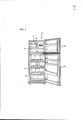
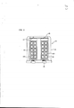
[003] A Figura 1 é uma vista frontal que mostra o interior de uma geladeira dotada de um dispositivo para fabricar gelo convencional, e a Figura 2 é uma vista em planta que mostra o dispositivo para fabricar gelo apresentado na geladeira mostrada na Figura 1.[003] Figure 1 is a front view showing the interior of a refrigerator provided with a conventional ice making device, and Figure 2 is a plan view showing the ice making device shown in the refrigerator shown in Figure 1.
[004] Conforme mostrado nestas figuras, as câmaras de congelamento e refrigeração 11 e 13, que são divididas em sentido vertical, são instaladas dentro de um corpo principal 10 de uma geladeira. O corpo principal 10 é dotado de uma porta 11D da câmara de congelamento e de uma porta 13D da câmara de refrigeração de modo a se abrirem ou fecharem seletivamente as câmaras de congelamento e refrigeração 11 e 13, respectivamente. Cada uma das portas 11D e 13D das câmaras de congelamento e refrigeração é articulada ao longo de um lado do corpo principal 10.[004] As shown in these figures, the freezing and
[005] Uma série de prateleiras 15 e 17 são instaladas de maneira removível dentro das câmaras de congelamento e refri-geração 11 e 13. As câmaras de congelamento e refrigeração 11 e 13 são divididas em sentido vertical pelas prateleiras 15 e 17, respectivamente. Um par de caixas para vegetais 19 são instaladas de maneira retrátil na parte inferir da câmara de refrigeração 13. Alimentos tais como vegetais são guardados nas caixas para vegetais 19.[005] A series of
[006] Além disso, um dispositivo para fabricar gelo 21 é instalado em um lado da parte superior da câmara de congela-mento 11. O dispositivo para fabricar gelo 21 é utilizado para fabricar gelo. Conforme mostrado na Figura 2, o dispositivo para fabricar gelo 21 é instalado de maneira retrátil dentro da câmara de congelamento 11. Além disto, o dispositivo para fabricar gelo 21 é composto de uma armação de sustentação 23 e um par de bandejas para gelo 25.[006] In addition, an
[007] A armação de sustentação 23 é tem a conformação de armação retangular. Cada uma das bandejas para gelo 25 é for-mada com uma série de ranhuras para fabricação de gelo 25A. Eixos de sustentação 26 são apresentados nos centros das su-perficies frontal e traseira das bandejas para gelo 25, res-pectivamente. A bandeja para gelo 25 é sustentada sobre a ar-mação de sustentação 23 de modo que possa ser girada em sentido horário ou em sentido anti-horário em volta do eixo de sustentação 26, conforme visto na Figura 2. Para isto, o eixo de sustentação 26 é rotativamente inserido na superficie traseira da armação de sustentação 23.[007] The
[008] Uma trava 27 é instalada de modo a projetar-se a partir da superficie traseira da armação de sustentação 23 em uma determinada posição dela que corresponde ao lado esquerdo do eixo de sustentação, conforme visto na Figura 2. A trava 27 permite que a extremidade dianteira da bandeja para gelo 27 seja torcida com relação à extremidade traseira da bandeja para gelo que gira em volta do eixo de sustentação 26.[008] A
[009] Um par de alavancas 28 é instalado sobre a superfície frontal da armação de sustentação 23 que corresponde ao lado frontal da bandeja para gelo 25. A alavanca 28 é a parte que o usuário segura para girar a bandeja para gelo 25. A alavanca 28 é ligada ao eixo de sustentação 26 instalado na superfície frontal da bandeja para gelo 25.[009] A pair of
[010] Novamente com referência à Figura 1, um banco de gelo 29 é instalado abaixo do dispositivo para fabricar gelo 21 dentro da câmara de congelamento 11. O gelo fabricado no dispositivo para fabricar gelo 21 é guardado no banco de gelo 29. O banco de gelo 29 é também instalado de maneira retrátil dentro da câmara de congelamento 11.[010] Again with reference to Figure 1, an ice bank 29 is installed below the
[011] Será explicado a seguir um processo para fabricar gelo com a utilização do dispositivo para fabricar gelo configurado como tal.[011] A process for making ice using the device for making ice configured as such will be explained below.
[012] Em primeiro lugar, as ranhuras para fabricação de gelo 25A da bandeja para gelo 25 são enchidas com água. A porta 11D da câmara de congelamento é aberta de para colocação do dispositivo para fabricar gelo 21 em uma posição predeterminada na câmara de congelamento 11. Depois que o dispositivo para fabricar gelo 21 tiver sido colocado na câmara de congelamento 11 dessa maneira, a porta 11D da câmara de congelamento é fechada para o fechamento da câmara de congelamento 11.[012] First, the 25A ice slots on the 25 ice tray are filled with water. The freezing chamber door 11D is opened to place the
[013] Nesse meio tempo, se a água contida nas ranhuras para fabricação de gelo 25A é congelada após um determinado periodo de tempo, a porta 11D da câmara de congelamento é no- vamente aberta para se abrir a câmara de congelamento 11. Se a alavanca 28 for girada em sentido horário, conforme visto na Figura 2, a bandeja para gelo 25 é torcida. Portanto, o gelo fabricado nas ranhuras para fabricação de gelo 25A é separado da bandeja para gelo 25 e em seguida armazenado no banco de gelo 29.[013] In the meantime, if the water contained in the 25A ice making slots is frozen after a certain period of time, the freezer chamber door 11D is opened again to open the
[014] Entretanto, o dispositivo para fabricar gelo con-vencional tem os problemas seguintes.[014] However, the conventional ice-making device has the following problems.
[015] Se o usuário desejar retirar o banco de gelo 29, no qual o gelo fabricado na bandeja para gelo 25 é armazenado, da câmara de congelamento 11, ele deve puxar a porta 11D da câmara de congelamento de modo a abrir a câmara de congelamento 11. Assim, é problemático colocar o banco de gelo 27 dentro ou para fora da câmara de congelamento.[015] If the user wishes to remove the ice bank 29, in which the ice manufactured in the
[016] Além do mais, quando a câmara de congelamento 11 é aberta para a retirada do banco de gelo 29 da câmara de congelamento, o ar frio na câmara de congelamento 11 é descarregado no lado de fora. Ou seja, no dispositivo para fabricar gelo convencional para uma geladeira, o ar frio na câmara de congelamento 11 é descarregado desnecessariamente no lado de fora enquanto o banco de gelo 29 é retirado da geladeira. Assim, o consumo de energia da geladeira é aumentado.[016] Furthermore, when the
[017] Além disso, o banco de gelo 29 é acomodado na câmara de congelamento 11. Assim, é provável que o gelo armazenado no banco de gelo 29 esteja impregnado com o odor de outros alimentos armazenados na câmara de congelamento 11.[017] In addition, the ice bank 29 is accommodated in the
[018] Além disso, no dispositivo para fabricar gelo con-vencional para uma geladeira, a água contida nas ranhuras para fabricação de gelo 25A da bandeja para gelo 25 é congelada em gelo, após um período predeterminado de gelo, devido ao ar frio que circula na câmara de congelamento 11. Ou seja, a água contida nas ranhuras para fabricação de gelo 25A da bandeja para gelo 25 pode ser esparrinhada para fora das ranhuras devido ao impacto gerado com a abertura ou fechamento da porta 11D da câmara de congelamento. Portanto, a câmara de congelamento 11 pode ser contaminada pela água esparrinhada.[018] In addition, in the conventional ice maker for a refrigerator, the water contained in the
[019] Por conseguinte, a presente invenção é concebida para solucionar os problemas da técnica anterior. É um objeto da presente invenção apresentar um dispositivo para fabricar gelo para uma geladeira capaz de retirar gelo de maneira mais simples.[019] Therefore, the present invention is designed to solve the problems of the prior art. It is an object of the present invention to present a device for making ice for a refrigerator capable of removing ice in a simpler way.
[020] É outro objeto da presente invenção apresentar um dispositivo para fabricar gelo para uma geladeira capaz de reduzir ao mínimo a perda do ar frio que circula em um espaço de armazenamento quando o gelo é retirado.[020] It is another object of the present invention to present a device for making ice for a refrigerator capable of minimizing the loss of cold air circulating in a storage space when the ice is removed.
[021] É outro objeto da presente invenção apresentar um dispositivo para fabricar gelo para uma geladeira capaz de impedir que o gelo armazenado em um banco de gelo seja impregnado com o odor de outros alimentos.[021] It is another object of the present invention to present a device for making ice for a refrigerator capable of preventing the ice stored in an ice bank from being impregnated with the odor of other foods.
[022] É ainda outro objeto da presente invenção é apre-sentar um dispositivo para fabricar gelo para uma geladeira capaz de reduzir ao mínimo a contaminação na geladeira no processo de fabricação de gelo.[022] It is yet another object of the present invention to present a device for making ice for a refrigerator capable of minimizing contamination in the refrigerator in the ice making process.
[023] De acordo com um aspecto da presente invenção, para a consecução dos objetos é apresentado um dispositivo para fabricar gelo para uma geladeira que compreende um tanque de água instalado, de modo removível, sobre a superficie traseira da porta de uma geladeira para abrir e fechar seletivamente um espaço de armazenamento, uma primeira e segunda bandejas para gelo rotativamente instaladas sobre a superficie traseira da porta para fabricar gelo com a utilização da água fornecida do tanque de água, e um banco de gelo instalado sobre a superficie traseira da porta para armazenar nela o gelo fabricado nas bandejas para gelo.[023] In accordance with an aspect of the present invention, a device for making ice is presented for a refrigerator which comprises a water tank removably installed on the rear surface of a refrigerator door to open and selectively close a storage space, a first and second ice trays rotatably installed on the rear surface of the door to make ice using the water supplied from the water tank, and an ice bank installed on the rear surface of the door for store the ice made in the ice trays in it.
[024] O tanque de água pode ser dividido em um primeiro e um segundo espaços de armazenamento de água dos quais a água é fornecida às primeira e segunda bandejas para gelo, respectivamente .[024] The water tank can be divided into a first and a second water storage space from which water is supplied to the first and second ice trays, respectively.
[025] A água armazenada nos primeiro e segundo espaços de armazenamento de água pode ser fornecida simultaneamente às primeira e segunda bandejas para gelo, respectivamente, por meio de um conjunto de válvula atuado quando o tanque de água é montado sobre a superficie traseira da porta.[025] The water stored in the first and second water storage spaces can be supplied simultaneously to the first and second ice trays, respectively, through a valve assembly actuated when the water tank is mounted on the back surface of the door. .
[026] O dispositivo para fabricar gelo da presente invenção pode compreender também um dispositivo de fornecimento de água para fornecer a água armazenada em qualquer um dos primeiro e segundo espaços de armazenamento a uma das primeira e segunda bandejas para gelo posicionada relativamente mais baixo que a outra das primeira e segunda bandejas para gelo instaladas sobre a superficie traseira da porta, de modo que as bandejas para gelo fiquem afastadas uma da outra por distâncias predeterminadas tanto da direção horizontal quanto na direção para frente ou para trás.[026] The ice making device of the present invention may also comprise a water supply device for supplying the water stored in any of the first and second storage spaces to one of the first and second ice trays positioned relatively lower than the another of the first and second ice trays installed on the rear surface of the door, so that the ice trays are spaced apart from each other by predetermined distances both in the horizontal direction and in the forward or backward direction.
[027] O dispositivo de fornecimento de água pode compre- ender uma tremonha de fornecimento de água instalada imediatamente abaixo do tanque de água para receber água de qualquer um dos primeiro e segundo espaços de armazenamento do tanque de água e um tubo de fornecimento de água, que inclui uma extremidade ligada à parte inferior da tremonha de fornecimento de água e a outra extremidade posicionada imediatamente a cima da bandeja para gelo inferior para permitir que a água fornecida à tremonha de fornecimento de água seja distribuída para a bandeja para gelo inferior.[027] The water supply device may comprise a water supply hopper installed immediately below the water tank to receive water from any of the first and second water tank storage spaces and a water supply tube. , which includes one end attached to the bottom of the water supply hopper and the other end positioned immediately above the bottom ice tray to allow water supplied to the water supply hopper to be distributed to the bottom ice tray.
[028] De preferência, o tubo de fornecimento de água é formado por um material flexível.[028] Preferably, the water supply pipe is formed of a flexible material.
[029] O dispositivo de fornecimento de água pode compre-ender uma tremonha de fornecimento de água instalada imediatamente abaixo do tanque de água de modo a receber água de qualquer um dos primeiro e segundo espaços de armazenamento de água do tanque de água, e um tubo de fornecimento de água instalado abaixo da parte inferior da tremonha de fornecimento de água para fornecer água à bandeja para gelo e formado com uma guia de extremidade saliente.[029] The water supply device may comprise a water supply hopper installed immediately below the water tank in order to receive water from any of the first and second water storage spaces in the water tank, and a water supply tube installed below the bottom of the water supply hopper to supply water to the ice tray and formed with a protruding end guide.
[030] O tubo de fornecimento de água pode ser formado de modo que sua extremidade distai fique inclinada a um ângulo agudo com relação à direção de extensão do tubo de fornecimento de água.[030] The water supply pipe may be formed so that its distal end is inclined at an acute angle with respect to the direction of extension of the water supply pipe.
[031] O dispositivo para fabricar gelo da presente invenção pode compreender também um alojamento para fabricação de gelo instalado sobre a superficie traseira da porta e dotado de um espaço de instalação no qual são instalados o tanque de água, as primeira e segunda bandejas para gelo e o banco de gelo.[031] The ice maker of the present invention may also comprise an ice maker housing installed on the rear surface of the door and provided with an installation space in which the water tank, the first and second ice trays are installed. and the ice bank.
[032] O dispositivo para fabricar gelo da presente invenção pode compreender também uma tampa de alojamento para cobrir o espaço de instalação do alojamento para fabricação de gelo em um estado no qual o tanque de água é instalado na parte superior do espaço de instalação do alojamento para fabricação de gelo.[032] The ice-making device of the present invention may also comprise a housing cover to cover the installation space of the ice-making housing in a state in which the water tank is installed at the top of the housing installation space for ice making.
[033] A tampa do alojamento pode ser formada de maneira integrante com a superfície superior do tanque de água.[033] The housing cover can be formed integrally with the top surface of the water tank.
[034] De acordo com outro aspecto da presente invenção, é apresentado um dispositivo para fabricar gelo para uma geladeira que compreende um tanque de água instalado de maneira removível sobre a superfície traseira da porta de uma geladeira para abrir ou fechar seletivamente um espaço de armazenamento, uma primeira e segunda bandejas para gelo rotativamente instaladas sobre a superfície traseira da porta para fabricar gelo com a utilização da água fornecida do tanque de água, e um meio de rotação instalado sobre a superfície traseira da porta, de modo a girar simultaneamente as primeira e segunda bandejas para gelo, de modo que as primeira e segunda bandejas para gelo possam ser torcidas para separar o gelo fabricado das primeira e segunda bandejas para gelo.[034] In accordance with another aspect of the present invention, a device for making ice for a refrigerator is presented which comprises a water tank removably installed on the rear surface of a refrigerator door to open or selectively close a storage space , a first and second ice trays rotatably installed on the rear surface of the door to make ice using the water supplied from the water tank, and a means of rotation installed on the rear surface of the door, so as to simultaneously rotate the first and second ice trays, so that the first and second ice trays can be twisted to separate the manufactured ice from the first and second ice trays.
[035] O meio de rotação pode compreender uma primeira engrenagem ligada com qualquer um de um par de eixos de rotação para permitir que a primeira bandeja para gelo seja rotativamente sustentada sobre a superfície traseira da porta, uma segunda engrenagem ligada com qualquer um de um par de eixos de rotação para permitir que a segunda bandeja para gelo seja rotativamente sustentada sobre a superfície traseira da porta, e pelo menos uma engrenagem de ligação engatada com as primeira e segunda engrenagens.[035] The rotating means may comprise a first gear connected with any one of a pair of axes of rotation to allow the first ice tray to be rotatably supported on the rear surface of the door, a second gear connected with either one pair of axes of rotation to allow the second ice tray to be rotatably supported on the rear surface of the door, and at least one connecting gear engaged with the first and second gears.
[036] O meio de rotação pode compreender também uma ala-vanca fixada na engrenagem de ligação de modo que o usuário possa segurar a alavanca para girar as primeira e segunda bandejas para gelo.[036] The means of rotation may also comprise a lever-wing attached to the connecting gear so that the user can hold the lever to rotate the first and second ice trays.
[037] A alavanca pode incluir uma parte de ligação que tem uma extremidade ligada a qualquer uma das primeira e se-gunda engrenagens e à engrenagem de ligação e uma parte de segurar ligada à outra extremidade da parte de ligação, de modo que o usuário possa segurar a parte de segurar para girar as primeira e segunda bandejas para gelo.[037] The lever may include a connecting part having an end connected to any of the first and second gears and the connecting gear and a holding part connected to the other end of the connecting part, so that the user can hold the holding part to rotate the first and second ice trays.
[038] O meio de rotação pode compreender também um ele-mento elástico para permitir que as primeira e segunda engre-nagens e a engrenagem de ligação imprimam uma força elástica à primeira ou segunda bandeja para gelo na direção oposta à direção na qual a primeira ou segunda bandeja para gero é girada para separar o gelo da bandeja.[038] The rotating means may also comprise an elastic element to allow the first and second gears and the connecting gear to impart an elastic force to the first or second ice tray in the direction opposite to the direction in which the first or second tray for gero is rotated to separate the ice from the tray.
[039] Cada uma das primeira e segunda bandejas pode ser formada de modo a ter um corte transversal retangular e é gi-rada em volta de eixos de rotação apresentados sobre as superficies laterais opostas dela.[039] Each of the first and second trays can be formed so as to have a rectangular cross-section and is rotated around axes of rotation presented on the opposite lateral surfaces of it.
[040] A primeira ou segunda bandeja para gelo pode ser mantida em um estado horizontal por meio de uma trava de ban-deja instalada sobre a superficie traseira da porta e ser torcida por uma força necessária para articular a primeira ou segunda bandeja para gelo em um estado no qual uma parte da bandeja para gelo é posta em contato intimo com a trava de bandeja depois que a bandeja tiver sido girada em um ângulo de rotação predeterminado.[040] The first or second ice tray can be held in a horizontal state by means of a banja deja lock installed on the rear surface of the door and twisted by a force necessary to articulate the first or second ice tray in a state in which a part of the ice tray is brought into intimate contact with the tray lock after the tray has been rotated at a predetermined angle of rotation.
[041] De preferência, uma projeção de guia é apresentada sobre qualquer uma das superficies opostas da primeira ou se-gunda bandeja para gelo de modo a ficar afastada do eixo de rotação por uma distância predeterminada, uma fenda de guia é formada em uma conformação de arco que tem um ângulo central predeterminado em volta do eixo de rotação da primeira ou se-gunda bandeja para gelo e é formada na superficie traseira da porta para permitir que a projeção de guia seja inserida nela, e a projeção de guia é movida de uma extremidade da fenda de guia até a outra extremidade da fenda à medida que a primeira ou segunda bandeja para gelo seja girada em volta do eixo de rotação.[041] Preferably, a guide projection is presented on any of the opposite surfaces of the first or second ice tray so as to be away from the axis of rotation by a predetermined distance, a guide slot is formed in a conformation arc that has a predetermined central angle around the axis of rotation of the first or second ice tray and is formed on the rear surface of the door to allow the guide projection to be inserted into it, and the guide projection is moved one end of the guide slot to the other end of the slot as the first or second ice tray is rotated around the axis of rotation.
[042] A primeira ou segunda bandeja para gelo pode com-preender também uma primeira ou segunda tampa de bandeja para impedir que a água armazenada no tanque de água seja esparri-nhada para fora da bandeja para gelo enquanto a água é forne-cida à primeira ou segunda bandeja para gelo.[042] The first or second ice tray can also comprise a first or second tray lid to prevent water stored in the water tank from being spread out of the ice tray while water is being supplied to the first or second ice tray.
[043] A tampa de bandeja pode inclui um corpo principal de tampa de bandeja com a conformação retangular que corres-ponde à superficie superior da bandeja para gelo e dotado de um orifício de fornecimento de água, através do qual a água distribuída do tanque de água é fornecida à bandeja para gelo, no centro dela, e uma nervura de guia, que se estende para baixo a partir da periferia externa na superficie inferior do corpo principal da bandeja e que tem uma extremidade dianteira da nervura de contato posta em contato intimo com a borda superior da primeira ou segunda bandeja para gelo.[043] The tray cover may include a main body of the tray cover with a rectangular conformation that corresponds to the upper surface of the ice tray and provided with a water supply hole, through which the water distributed from the storage tank. water is supplied to the ice tray in the center of it and a guide rib extending downwards from the outer periphery on the lower surface of the main body of the tray and which has a front end of the contact rib brought into close contact with the top edge of the first or second ice tray.
[044] A tampa de bandeja pode ser instalada de modo que qualquer uma de ambas as extremidades da tampa de bandeja pa- ralela ao eixo de rotação, que permite que a bandeja para gelo seja rotativamente sustentada sobre a superfície traseira da porta, seja articulada na outra extremidade da tampa de bandeja na direção oposta à direção de rotação da bandeja para gelo à medida que a bandeja para gelo é girada para separar o gelo da bandeja para gelo.[044] The tray cover can be installed so that either end of the tray cover parallel to the axis of rotation, which allows the ice tray to be rotatably supported on the rear door surface, is pivoted at the other end of the tray cover in the opposite direction to the direction of rotation of the ice tray as the ice tray is rotated to separate the ice from the ice tray.
[045] A extremidade de articulação da tampa da bandeja para gelo pode ser posta em contato intimo com a trava de guia apresentado sobre a superfície traseira da porta, para permitir que a extremidade de articulação seja relativamente articulada na outra extremidade da tampa de bandeja com relação à bandeja para gelo na direção oposta à direção de rotação da bandeja para gelo para separar o gelo da bandeja para gelo.[045] The hinge end of the ice tray cover can be brought into close contact with the guide lock shown on the rear surface of the door, to allow the hinge end to be relatively hinged on the other end of the tray cover with relative to the ice tray in the opposite direction to the rotation direction of the ice tray to separate the ice from the ice tray.
[046] O dispositivo para fabricar gelo da presente invenção pode compreender também um alojamento para fabricação de gelo para uma geladeira instalado sobre a superfície traseira da porta e dotado de um espaço de instalação no qual são instalados o tanque de água, as primeira e segunda bandejas pare gelo, o meio de rotação e as primeira e segunda tampas de ban- de j a.[046] The ice-making device of the present invention may also comprise an ice-making housing for a refrigerator installed on the rear surface of the door and provided with an installation space in which the water tank, the first and second, are installed. trays for ice, the means of rotation and the first and second seat covers.
[047] De acordo com outro aspecto da presente invenção, é apresentado um dispositivo para fabricar gelo para uma geladeira que compreende uma primeira e uma segunda bandejas para gelo rotativamente instaladas sobre a superfície traseira da porta de uma geladeira para abrir ou fechar seletivamente um espaço de armazenamento para fabricar gelo com a utilização da água fornecida, e um banco de gelo instalado de modo a ser recebido em, ou retirado de, uma abertura formada recortando-se uma parte da superfície frontal da porta e para armazenar nela o gelo fabricado nas bandejas para gelo.[047] In accordance with another aspect of the present invention, a device for making ice for a refrigerator is presented which comprises a first and a second ice trays rotatably installed on the rear surface of a refrigerator door to selectively open or close a space of storage to make ice using the supplied water, and an ice bank installed in order to be received in, or removed from, an opening formed by cutting a part of the front surface of the door and to store the ice made in ice trays.
[048] 0 banco de gelo pode ser instalado de modo a ser recebido em, ou retirado de, um espaço de instalação definido dentro do alojamento para fabricação de gelo instalado, de modo removível, sobre a superficie traseira da porta.[048] The ice bank can be installed in order to be received in, or removed from, an installation space defined within the ice-making housing installed, removably, on the rear surface of the door.
[049] O banco de gelo pode ser recebido ou retirado na direção frontal da porta através da abertura e de uma primeira entrada do banco de gelo formada sobre a superficie traseira do alojamento para fabricação de gelo posta em contato intimo com a superficie traseira da porta e ser recebido ou retirado na direção traseira da porta através de uma segunda entrada do banco de gelo formada sobre a superficie frontal do alojamento para fabricação de gelo paralela à superficie traseira da porta .[049] The ice bank can be received or removed in the front direction of the door through the opening and a first entrance of the ice bank formed on the rear surface of the ice-making housing placed in close contact with the rear surface of the door and be received or removed in the rear direction of the door through a second ice bank entrance formed on the front surface of the ice making housing parallel to the rear surface of the door.
[050] O dispositivo para fabricar gelo da presente invenção pode compreender também um meio de cooperação para permitir que o banco de gelo seja recebido no, ou retirado do, espaço de instalação do alojamento para fabricação de gelo de acordo com o movimento de articulação de uma porta com barra caseira em uma parte sobre a superficie frontal da porta, de modo que a extremidade superior da porta com barra caseira seja articulada em sentido vertical na extremidade inferior da porta com barra caseira de modo a abrir ou fechar seletivamente a abertura.[050] The ice-making device of the present invention may also comprise a cooperative means to allow the ice bank to be received in, or removed from, the installation space of the ice-making housing according to the articulation movement of a door with a homemade bar in a part on the front surface of the door, so that the upper end of the door with a homemade bar is hinged vertically in the lower end of the door with a homemade bar in order to selectively open or close the opening.
[051] O meio de cooperação pode incluir uma chapa de as-sentamento instalada de modo a poder mover-se para dentro ou para fora do espaço de instalação do alojamento para fabrica-ção de gelo, para permitir que o banco de gelo seja colocado de maneira segura nele, e uma chapa de cooperação formada com uma extremidade traseira ligada de maneira articulada a uma extremidade frontal da chapa de assentamento e uma extremidade frontal fixada na superficie traseira da porta com barra caseira, de modo que o banco de gelo seja recebido no, ou retirado do, espaço de instalação do alojamento para fabricação de gelo à medida que a porta com barra caseira é articulada.[051] The means of cooperation may include a seating plate installed in order to be able to move in or out of the installation space of the housing for ice making, to allow the ice bank to be placed securely in it, and a cooperation plate formed with a rear end hingedly connected to a front end of the laying plate and a front end fixed to the rear surface of the door with homemade bar, so that the ice bank is received in, or removed from, the installation space of the housing for making ice as the door with a homemade bar is hinged.
[052] De preferência, pelo menos uma projeção para pre-venção de movimento e pelo menos uma ranhura de prevenção de movimento são formadas sobre a superficie inferior do banco de gelo e sobre a superficie superior da chapa de assentamento, respectivamente, de modo que a projeção seja inserida na ranhura de modo a impedir que a projeção e a ranhura sejam inadvertidamente movidas uma com relação à outra em um estado no qual o banco de gelo é colocado de maneira segura sobre a superficie superior da chapa de assentamento enquanto a chapa de assentamento é movida para dentro ou para fora do espaço de instalação.[052] Preferably, at least one projection for movement prevention and at least one movement prevention groove are formed on the lower surface of the ice bank and on the upper surface of the laying plate, respectively, so that the projection is inserted into the groove to prevent the projection and the groove from being inadvertently moved relative to each other in a state in which the ice bank is placed securely on the top surface of the laying plate while the settlement is moved into or out of the installation space.
[053] Pelo menos um orifício de drenagem de água pode ser formado na chapa de assentamento para permitir que a água existente entre a superficie inferior do banco de gelo e a superficie superior da chapa de assentamento seja drenada para baixo.[053] At least one water drainage hole can be formed in the bottom plate to allow the water between the bottom surface of the ice bank and the top surface of the bottom plate to be drained downwards.
[054] Cada lado da chapa de assentamento pode ser dotado de pelo menos um cilindro móvel, que é movido ao longo da su-perficie de piso do alojamento para fabricação de gelo, en-quanto a chapa de assentamento é movida para dentro ou para fora do espaço de instalação do alojamento para fabricação de gelo à medida que a porta com barra caseira é articulada.[054] Each side of the laying plate can be provided with at least one movable cylinder, which is moved along the floor surface of the housing for making ice, while the laying plate is moved inward or outward. outside the installation space of the housing for making ice as the door with a homemade bar is hinged.
[055] Cada uma das extremidades frontal e traseira do banco de gelo pode ser dotada de um recesso de preensão que o usuário segura para permitir que o banco de gelo seja recebido no, ou retirado do, alojamento para fabricação de gelo.[055] Each of the front and rear ends of the ice bank can be provided with a gripping recess that the user holds to allow the ice bank to be received in, or removed from, the ice maker housing.
[056] De preferência, o recesso de preensão pode ser formado calcando-se para cima uma parte da extremidade frontal ou traseira do banco de gelo, e uma abertura de preensão é apresentada na extremidade frontal ou traseira da chapa de assentamento recortando-se uma parte da chapa de assentamento para que corresponda ao corte transversal do recesso de preensão, de modo que o usuário possa segurar com facilidade o recesso de preensão.[056] Preferably, the gripping recess can be formed by pressing a part of the front or rear end of the ice bank upwards, and a gripping opening is shown at the front or rear end of the laying plate by cutting a part of the laying plate so that it corresponds to the cross section of the gripping recess, so that the user can easily hold the gripping recess.
[057] De acordo com ainda outro aspecto da presente in-venção, é apresentado um dispositivo para fabricar gelo para uma geladeira que compreende um alojamento para fabricação de gelo instalado sobre a superfície traseira da porta de uma geladeira para abrir ou fechar seletivamente um espaço de armazenamento e dotado de um espaço de instalação predeterminado, um tanque de água instalado, de modo removível, no espaço de instalação do alojamento para fabricação de gelo, uma primeira e segunda bandejas para gelo rotativamente instaladas no espaço de instalação do alojamento para fabricação de gelo de modo a se fabricar gelo com a utilização da água fornecida do tanque de água, um banco de gelo instalado de maneira retrátil no espaço de instalação do alojamento para fabricação de gelo, de modo a armazenar nele o gelo fabricado nas primeira e segunda bandejas para gelo, e um meio de montagem para montar, de modo removível, o alojamento para fabricação de gelo sobre a superfície traseira da porta.[057] In accordance with yet another aspect of the present invention, a device for making ice for a refrigerator is presented, comprising an ice-making housing installed on the rear surface of a refrigerator door to selectively open or close a space storage space and provided with a predetermined installation space, a water tank, removably installed, in the installation space of the housing for making ice, a first and second ice trays rotatingly installed in the installation space of the housing for manufacturing ice. ice in order to make ice using the water supplied from the water tank, a retractable ice bank installed in the installation space of the ice making housing, in order to store the ice made in the first and second trays in it for ice, and a mounting means for removably mounting the ice maker housing on the rear surface of the ice orta.
[058] O meio de montagem pode incluir pelo menos uma pro- jeção de montagem formada sobre a superficie interna de uma parte sulcada que se estende em sentido vertical em uma, e que se projeta para trás a partir de uma, extremidade lateral da superficie traseira da porta, pelo menos uma ranhura de assentamento formada em uma extremidade lateral do alojamento para fabricação de gelo para permitir que a projeção de montagem da parte sulcada seja encaixada nele, pelo menos uma projeção de montagem formada no outro lado do alojamento para fabricação de gelo, e pelo menos uma ranhura de montagem formada sobre uma superficie lateral de uma cesta de porta instalada, de modo removível, sobre a superficie traseira da porta para permitir que a projeção de montagem do alojamento para fabricação de gelo seja encaixada nela.[058] The mounting means may include at least one mounting projection formed on the inner surface of a grooved part that extends vertically in one, and that protrudes backwards from one, lateral end of the surface at the rear of the door, at least one seating groove formed on one side end of the ice making ice, and at least one mounting groove formed on a side surface of a door basket removably installed on the rear surface of the door to allow the mounting projection of the ice making housing to be fitted thereon.
[059] O alojamento para fabricação de gelo pode incluir um primeiro alojamento para fabricação de gelo instalado, de modo removível, sobre a superficie traseira da porta e dotado de um primeiro espaço de instalação, no qual o tanque de água e o banco de gelo são instalados, e um segundo alojamento para fabricação de gelo, instalado, de modo removível, no primeiro espaço de instalação do primeiro alojamento para fabricação de gelo e dotado de um segundo espaço de instalação, no qual as primeira e segunda bandejas de gelo e o meio de rotação são instalados.[059] The ice-making housing may include a first ice-making housing that is removably installed on the rear surface of the door and provided with a first installation space, in which the water tank and the ice bank are installed, and a second housing for making ice, removably installed in the first installation space of the first housing for making ice and provided with a second installation space, in which the first and second ice trays and the rotation means are installed.
[060] A projeção de montagem encaixada na ranhura de montagem da cesta da porta pode ser apresentada em uma superficie lateral do primeiro alojamento para fabricação de gelo, e a ranhura de montagem na qual a projeção de montagem da parte sulcada é encaixada pode ser apresentada em uma superficie lateral do segundo alojamento para fabricação de gelo.[060] The mounting projection embedded in the mounting groove of the door basket can be presented on a side surface of the first housing for making ice, and the mounting groove in which the mounting projection of the grooved part is fitted can be presented on a side surface of the second ice-making housing.
[061] De preferência, é formado, sobre a superficie ex-terna traseira do segundo alojamento para fabricação de gelo, um recesso, no qual é inserido um degrau de assentamento que se estende na direção horizontal ao longo da superficie tra-seira da porta e se projeta para trás a partir da superficie traseira da porta de modo a sustentar a cesta de porta.[061] Preferably, a recess is formed on the ex-ternal rear surface of the second ice-making housing, in which a seating step is inserted that extends in the horizontal direction along the rear surface of the door and protrudes backwards from the rear surface of the door to support the door basket.
[062] Uma janela de exibição, para verificar visualmente se o gelo é fabricado nas primeira e segunda bandejas, e pelo menos um orificio de fornecimento de ar frio para fornecer às primeira e segunda bandejas para gelo ar frio circulante no espaço de armazenamento, podem ser apresentados em um lado do segundo alojamento para fabricação de gelo.[062] A display window, to visually check whether ice is made in the first and second trays, and at least one cold air supply port to provide the first and second ice trays with cold air circulating in the storage space, can be presented on one side of the second ice-making housing.
[063] De acordo com a presente invenção, o banco de gelo com gelo armazenado nele pode ser adequadamente recebido na, ou retirado da, geladeira por meio de uma operação de abrir ou fechar a porta com barra caseira. Portanto, o usuário pode facilmente tirar o gelo da geladeira.[063] According to the present invention, the ice bank with ice stored in it can be properly received in, or removed from, the refrigerator by means of an operation of opening or closing the door with a homemade bar. Therefore, the user can easily take the ice out of the refrigerator.
[064] Além disso, o banco de gelo com gelo armazenado nele pode ser recebido na, ou retirado da, geladeira abrindo-se apenas a porta com barra caseira sem se abrir a porta da geladeira. Portanto, a quantidade de ar que circula no espaço de armazenamento da geladeira a escapar para o lado de fora é reduzida ao minimo, de modo que a geladeira pode ser utilizada de maneira mais econômica.[064] In addition, the ice bank with ice stored in it can be received in, or removed from, the refrigerator by opening only the door with a homemade bar without opening the refrigerator door. Therefore, the amount of air circulating in the refrigerator storage space escaping to the outside is reduced to a minimum, so that the refrigerator can be used more economically.
[065] Além disso, o banco de gelo com gelo armazenado nele é acomodado no espaço de instalação adicional separado do espaço de armazenamento. Portanto, o fenômeno de o gelo armazenado no banco de gelo ser impregnado com o odor de outros alimentos armazenados no espaço de armazenamento é reduzido ao minimo e, assim, o gelo pode ser armazenado de maneira mais saudável.[065] In addition, the ice bank with ice stored in it is accommodated in the additional installation space separate from the storage space. Therefore, the phenomenon of ice stored in the ice bank being impregnated with the odor of other foods stored in the storage space is reduced to a minimum and, thus, ice can be stored in a healthier way.
[066] Além do mais, a tampa da bandeja impede que a água seja esparrinhada para fora da bandeja para gelo quando a água é fornecida à bandeja para gelo. Portanto, a contaminação do interior da geladeira devida à água pode ser reduzido ao minimo no processo de fabricação de gelo e, assim, a geladeira pode ser utilizada de maneira mais limpa.[066] Furthermore, the lid on the tray prevents water from being spilled out of the ice tray when water is supplied to the ice tray. Therefore, the contamination of the interior of the refrigerator due to water can be reduced to a minimum in the ice making process and, thus, the refrigerator can be used more cleanly.
[067] A Figura 1 é uma vista frontal que mostra o interior de uma geladeira equipada com um dispositivo para fabricar gelo convencional.[067] Figure 1 is a front view showing the interior of a refrigerator equipped with a device for making conventional ice.
[068] A Figura 2 é uma vista frontal do dispositivo para fabricar gelo apresentado na geladeira mostrada na Figura 1.[068] Figure 2 is a front view of the ice maker shown in the refrigerator shown in Figure 1.
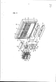
[069] A Figura 3 é uma vista em perspectiva de uma moda-lidade de um dispositivo para fabricar gelo para uma geladeira de acordo com a presente invenção.[069] Figure 3 is a perspective view of a fashion of a device for making ice for a refrigerator according to the present invention.
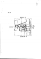
[070] A Figura 4 é uma vista em corte lateral que mostra a modalidade mostrada na Figura 3.[070] Figure 4 is a side section view showing the modality shown in Figure 3.
[071] A Figura 5 é uma vista em perspectiva recortada parcial que mostra em detalhe o estado no qual o tanque de água da modalidade mostrada na Figura 3 é montado em um alojamento para fabricação de gelo.[071] Figure 5 is a partial cut-away perspective view showing in detail the state in which the water tank of the modality shown in Figure 3 is mounted in an ice-making housing.
[072] A Figura 6 é uma vista em corte lateral que mostra em detalhe o estado no qual uma bandeja para gelo da modalidade mostrada na Figura 3 é montada no alojamento para fabricação de gelo.[072] Figure 6 is a side sectional view showing in detail the state in which an ice tray of the modality shown in Figure 3 is mounted in the ice maker.
[073] A Figura 7 é uma vista em corte lateral que mostra em detalhe o estado no qual um banco de gelo da modalidade mostrada na Figura 3 é acomodado no alojamento para fabricação de gelo.[073] Figure 7 is a side sectional view showing in detail the state in which an ice bank of the modality shown in Figure 3 is accommodated in the ice-making housing.
[074] A Figura 8 é uma vista em perspectiva que mostra um exemplo de dispositivo de fornecimento de água da modalidade mostrada na Figura 3.[074] Figure 8 is a perspective view showing an example of a water supply device of the modality shown in Figure 3.
[075] As Figuras 9 e 10 são vistas que mostram um processo no qual a bandeja para gelo da modalidade mostrada na Figura 3 é articulada.[075] Figures 9 and 10 are seen showing a process in which the ice tray of the modality shown in Figure 3 is hinged.
[076] As Figuras 11 e 12 são vistas que mostram um pro-cesso no qual o banco de gelo da modalidade mostrada na Figura 3 é retirado.[076] Figures 11 and 12 are seen showing a process in which the ice bank of the modality shown in Figure 3 is removed.
[077] A seguir será descrita em detalhe, com referência aos desenhos anexos, uma modalidade preferida de um dispositivo para fabricar gelo para uma geladeira de acordo com a presente invenção.[077] Below, a preferred embodiment of a device for making ice for a refrigerator according to the present invention will be described in detail, with reference to the accompanying drawings.
[078] A Figura 3 é uma vista em perspectiva explodida da modalidade preferida de um dispositivo para fabricar gelo para uma geladeira de acordo com a presente invenção; a Figura 4 é uma vista em corte lateral que mostra a modalidade mostrada na Figura 3; a Figura 5 é uma vista em perspectiva recortada parcial que mostra em detalhe o estado no qual o tanque de água da modalidade mostrada na Figura 3 é montado em um alojamento para fabricação de gelo; a Figura 6 é uma vista em corte lateral que mostra em detalhe o estado no qual uma bandeja para gelo da modalidade mostrada na Figura 3 é montada no alojamento para fabricação de gelo; e a Figura 7 é uma vista em corte transversal que mostra em detalhe o estado no qual o banco de gelo da modalidade mostrada na Figura 3 é acomodado no alojamento para fabricação de gelo.[078] Figure 3 is an exploded perspective view of the preferred embodiment of a device for making ice for a refrigerator according to the present invention; Figure 4 is a side sectional view showing the embodiment shown in Figure 3; Figure 5 is a partial cut-away perspective view showing in detail the state in which the water tank of the modality shown in Figure 3 is mounted in an ice-making housing; Figure 6 is a side sectional view showing in detail the state in which an ice tray of the modality shown in Figure 3 is mounted in the ice making housing; and Figure 7 is a cross-sectional view showing in detail the state in which the ice bank of the embodiment shown in Figure 3 is accommodated in the ice-making housing.
[079] Conforme mostrado nas figuras, um par de degraus de assentamento 110 e 120 e partes sulcadas 130 e 140 são instalados sobre a superficie traseira da porta 100 de uma geladeira. Os degraus de assentamento 110 e 120 são apresentados no centro e na extremidade inferior da porta 100 na direção horizontal. Além disto, as partes sulcadas 130 e 140 são apresentadas em ambas as extremidades laterais da superficie traseira da porta 110 na direção vertical.[079] As shown in the figures, a pair of
[080] Cestas de porta 170 e 180 ou alojamentos para fa-bricação de gelo 210 e 220, que serão explicados mais adiante, são colocados de maneira segura sobre as superficies superiores dos degraus de assentamento 110 e 120, respectivamente. Uma série de projeções de montagem 131 e 141 são apresentadas sobre as superficies opostas das partes sulcadas 130 e 140, respectivamente. As projeções de montagem 131 e 141 das partes sulcadas 130 e 140 são encaixadas em ranhuras de montagem 171 e 181 das cestas de porta 170 e 180 ou nas ranhuras de montagem dos alojamentos para fabricação de gelo 220.[080] Baskets 170 and 180 or
[081] Uma abertura 150 é apresentada em uma posição na porta 100. A abertura 150 é utilizada para tirar o banco de gelo 280, que será explicado mais adiante, da geladeira sem abrir a porta 100. Além disto, é apresentada uma porta com barra caseira 160 para abrir ou fechar seletivamente a abertura 150. A porta com barra caseira 160 é instalada na porta 100 de modo que seja articulada sobre um eixo de articulação 160H instalado na extremidade inferior da porta 100.[081] An
[082] Conforme mostrado em detalhe na Figura 7, uma ra- nhura de cooperação 161 é formada sobre a superficie traseira da porta com barra caseira 160. A ranhura de cooperação 161 é formada sobre a superficie traseira da porta com barra caseira 160 ao longo de uma linha horizontal afastada para baixo da extremidade superior da porta com barra caseira 160 por uma distância predeterminada. Uma nervura de cooperação 288 de uma chapa de cooperação 287, que será explicada mais adiante, é inserida na ranhura de cooperação 161.[082] As shown in detail in Figure 7, a
[083] Um par de cestas de porta 170 e 180 é apresentado sobre a superficie traseira da porta 100. Espaços receptores predeterminados 170S e 180S são definidos nas cestas de porta 170 e 180, respectivamente. As cestas de porta 170 e 180 são instaladas, de modo removível, sobre a superfície traseira da porta 100. Para isto, as ranhuras de montagem abertas para baixo 171 e 181 são formadas sobre ambas as superfícies late-rais externas das cestas de porta 170 e 180, respectivamente. As projeções de montagem 141 das partes sulcadas 130 e 140 são encaixadas nas ranhuras de montagem 171 e 181 posicionadas no lado direito das cestas de porta 170 e 180, conforme visto na Figura 3. Projeções de montagem 211 do alojamento para fabricação de gelo 210 são encaixadas nas ranhuras de montagem 171 e 181 posicionadas no lado esquerdo das cestas de porta 170 e 180, conforme visto na Figura 3.[083] A pair of door baskets 170 and 180 is shown on the rear surface of
[084] Um dispositivo para fabricar gelo 200 é apresentado sobre a superfície traseira da porta 100. O dispositivo para fabricar gelo 200 é instalado, de modo removível, sobre a superfície superior da porta 100. O dispositivo para fabricar gelo 200 compreende os alojamentos para fabricação de gelo 210 e 220, um tanque de água 230, bandejas para gelo 250 e 260 e o banco de gelo 280.[084] An ice maker 200 is presented on the rear surface of the
[085] Os alojamentos para fabricação de gelo 210 e 220 definem substancialmente a aparência externa do dispositivo para fabricar gelo 200. O tanque de água 230, as bandejas para gelo 250 e 260 e o banco de gelo 280 são instalados nos alojamentos para fabricação de gelo 210 e 220. Os alojamentos para fabricação de gelo 210 e 220 são divididos no primeiro alojamento para fabricação de gelo 210 e no segundo alojamento para fabricação de gelo 220.[085]
[086] O primeiro alojamento para fabricação de gelo 210 tem uma conformação hexaédrica com um topo aberto. Um primeiro espaço de instalação 210S é definido dentro do primeiro alojamento para fabricação de gelo 210. Uma série de projeções de montagem 211 é instalada no lado direito do primeiro alojamento para fabricação de gelo 210, conforme visto na Figura 3. As projeções de montagem 211 do primeiro alojamento para fabricação de gelo 210 são encaixadas nas ranhuras de montagem 171 e 181 das cestas de porta 170 e 180, respectivamente.[086] The first 210 ice maker housing has a hexahedral shape with an open top. A first installation space 210S is defined inside the
[087] Um recorte 212 é apresentado no lado direito do alojamento para fabricação de gelo 210. O recorte 212 é formado recortando-se uma parte do lado direito do alojamento para fabricação de gelo 210 com a conformação que corresponde ao corte transversal do degrau de assentamento 110 instalado no centro da superfície traseira da porta 100.[087] A cutout 212 is shown on the right side of the
[088] Uma entrada de alojamento 213 é apresentada no primeiro alojamento para fabricação de gelo 210. A entrada de alojamento 213 é formada cortando-se os lados frontal e tra-seira e uma parte do centro do lado esquerdo do primeiro alo-jamento para fabricação de gelo 210 em correspondência com a conformação e o tamanho do segundo alojamento para fabricação de gelo 220. A entrada de alojamento 213 funciona como uma entrada através da qual o segundo alojamento para fabricação de gelo 220 é instalado no e removível do primeiro espaço de instalação 210S.[088] A housing entrance 213 is shown in the first housing for ice making 210. Housing entrance 213 is formed by cutting the front and rear sides and a part of the center on the left side of the first accommodation for ice making 210 corresponding to the conformation and size of the second
[089] Uma parte de assentamento 215 do tanque de água é apresentada na parte superior do primeiro espaço de instalação 210S afastada para baixo da extremidade superior do primeiro alojamento para fabricação de gelo 210 por uma distância predeterminada. A parte de assentamento 215 do tanque de água é a parte na qual o tanque de água 230 é colocado de maneira segura. A parte de assentamento 215 do tanque de água é dotada de um par de orifícios de fornecimento de água 216A e 216B, que são divididos na direção direita ou esquerda. O orificio de fornecimento de água direito da parte de assentamento 215 do tanque de água é referido como o orificio de fornecimento de água 216A e o orificio de fornecimento de água esquerdo da parte de assentamento 215 do tanque de água é referido como o segundo orificio de fornecimento de água 216B, conforme visto na figura. Uma projeção de atuação 217 é apresentada no centro da superficie superior da parte de assentamento 215 do tanque de água, isto é, entre os primeiro e segundo orifícios de fornecimento de água 216A e 216B. A projeção de atuação 217 serve para atuar um conjunto de válvula 234 instalado no tanque de água 230.[089] A
[090] Ranhuras de assentamento 218 são apresentadas nas superficies laterais internas do primeiro alojamento para fa-bricação de gelo 210 instalado acima da parte de assentamento 215 do tanque de água, respectivamente. As ranhuras de assen- tamento 218 são abertas para cima, e uma projeção de assenta-mento 232 formada no tanque de água 230 é colocada de maneira segura em cada uma das ranhuras de assentamento 218.[090] Seating grooves 218 are shown on the inner side surfaces of the first
[091] Entradas 219A e 219B do banco de gelo são apresen-tadas nas partes inferiores das superficies traseira e frontal do primeiro alojamento para fabricação de gelo 210. As entradas 219A e 219B do banco de gelo são entradas através das quais o banco de gelo 280 é recebido no ou retirado do primeiro espaço de instalação 219B. Em seguida, a entrada formada na superfície inferior traseira do primeiro alojamento para fabricação de gelo 210 é referida como a primeira entrada 219A do banco de gelo, e a entrada formada na superfície inferior frontal do primeiro alojamento para fabricação de gelo 210 é referida como a segunda entrada 219B do banco de gelo.[091]
[092] O segundo alojamento para fabricação de gelo 220 tem uma conformação hexaédrica com o topo e a base abertos. Um segundo espaço de instalação 220S é definido dentro do segundo alojamento para fabricação de gelo 220. Uma série de ranhuras de montagem (não mostradas) é formada sobre a superfície esquerda do segundo alojamento para fabricação de gelo 220, conforme visto na Figura 3. As ranhuras de montagem 131 e 141 das partes sulcadas 130 e 140 são encaixadas nas ranhuras de montagem do segundo alojamento para fabricação de gelo 220, respectivamente .[092] The
[093] O segundo alojamento para fabricação de gelo 220 é instalado, de modo removível, no primeiro espaço de instalação 210S através da entrada de alojamento 213. Um recesso 222 é apresentado sobre a superfície traseira do segundo alojamento para fabricação de gelo 220. O recesso 222 é formado calcando- se uma parte da superficie traseira do segundo alojamento para fabricação de gelo 220, que corresponde à superficie traseira do primeiro alojamento para fabricação de gelo 210, na direção do segundo espaço de instalação 220S em uma profundidade predeterminada na direção direita ou esquerda em correspondência com o corte transversal do recorte 212. O degrau de assentamento 110 instalado no centro da superficie traseira da porta 100 é inserido no recesso 222.[093] The
[094] Uma janela de exibição 223 é apresentada sobre a superficie frontal do segundo alojamento para fabricação de gelo 220 em paralelo com a superficie traseira do segundo alojamento para fabricação de gelo 220. A janela de exibição 223 é utilizada para verificar visualmente o interior do segundo espaço de instalação 220S. A janela de exibição 223 é dotada de um par de orifícios de fornecimento de ar frio 224. Cada um dos orifícios de fornecimento de ar frio 224 é formado recortando-se uma parte da janela de exibição 223 na direção direita ou esquerda. Os orifícios de fornecimento de ar frio 224 são utilizados para permitir que o ar frio que circula no espaço de armazenamento fechado pela porta 100 seja introduzido no segundo espaço de instalação 220S e substancialmente nas bandejas para gelo 250 e 260.[094] A
[095] Conforme mostrado na Figura 6, é apresentado um par de orifícios para rotação 225A e 225B sobre cada uma das superfícies laterais do segundo alojamento para fabricação de gelo 220. Os orifícios para rotação 225A e 225B são utilizados sustentar de maneira rotativa as bandejas para gelo 250 e 260, respectivamente. Um par de fendas de guia 226A e 226B é formado sobre uma superfície lateral do segundo alojamento para fabricação de gelo 220, isto é, a superficie lateral esquerda, conforme visto na Figura 3, em adjacência aos orifícios para rotação 225A e 225B. As fendas de guia 226A e 226B tem uma conformação em arco que tem um ângulo central predeterminado em volta dos orifícios para rotação 225A e 225B. Na modalidade mostrada, as fendas de guia 226A e 226B têm uma conformação em arco que tem um ângulo central de aproximadamente 0 a 100 graus em volta dos orifícios para rotação 225A e 225B em uma coordenada cartesiana, conforme visto no segundo espaço de instalação na direção de uma superficie lateral interna do segundo alojamento para fabricação de gelo 220.[095] As shown in Figure 6, a pair of holes for
[096] Um par de bujões de bandeja 227A e 227B é apresen-tado sobre uma superficie lateral interna do segundo alojamento para fabricação de gelo 220 em adjacência aos orifícios para rotação 225A e 225B. Os bujões de bandeja 227A e 227B servem para manter as bandejas para gelo 250 e 260, que foram giradas em um determinado ângulo, de modo que as bandejas para gelo 250 e 260 possam ser torcidas.[096] A pair of tray plugs 227A and 227B is presented on an internal side surface of the second
[097] Além disso, um par de bujões de guia 228A e 228B é instalado sobre uma superficie lateral interna do segundo alojamento para fabricação de gelo 220 em posições opostas aos bujões de bandeja 227A e 227B com relação aos orifícios para rotação 225A e 225B. Os bujões de guia 228A e 228B servem para fazer com que as tampas de bandeja 253 e 263, que serão explicadas mais adiante, sejam articuladas de maneira relativa sobre as bandejas para gelo 250 e 260. Para isto, os bujões de guia 228A e 228B são postos em contato intimo com as tampas de bandeja 253 e 263. Isto será também descrito em detalhe a seguir .[097] In addition, a pair of guide plugs 228A and 228B is installed on an internal side surface of the second
[098] Novamente com referência à Figura 3, uma unidade de instalação de engrenagem 229 é instalada no segundo alojamento para fabricação de gelo 220 em adjacência ao segundo espaço de instalação 220S. A unidade de instalação de engrenagem 229 é a região na qual uma série de engrenagens para girar as bandejas para gelo 250 e 260 é instalada. Por exemplo, se o segundo alojamento para fabricação de gelo 220 for composto por alojamentos externos e internos que são postos em contato intimo uns com os outros em um lado deles que são afastados uns dos outros no outro lado deles, a unidade de instalação de engrenagem pode ser definida entre o lado interno do alojamento externo e o lado externo do alojamento interno.[098] Again with reference to Figure 3, a gear installation unit 229 is installed in the second
[099] Uma fenda para alavanca 229A é apresentada na ex-tremidade direita da extremidade frontal do segundo alojamento para fabricação de gelo 220, conforme visto na figura. A fenda para alavanca 229A é utilizada para guiar o movimento de uma alavanca 276 (que será descrito a seguir) para girar as bandejas para gelo 250 e 260. A fenda para alavanca 229A é formada na direção vertical na extremidade direita da superfície frontal do segundo alojamento para fabricação de gelo 220 de modo a comunicar-se com a unidade de instalação de engrenagem 229.[099] A slot for lever 229A is shown on the right extreme end of the front end of the second
[0100] Além disso, o tanque de água 230 é instalado, de modo removível, na parte superior do primeiro espaço de instalação 210S. Um espaço de armazenamento de água é definido dentro do tanque de água 230, conforme mostrado em detalhe na Figura 5. O espaço de armazenamento de água é composto por um primeiro e um segundo espaços de armazenamento de água 230A e 230B, que são divididos na direção direito ou esquerdo. A água que será fornecida às bandejas para gelo 250 e 260, isto é, as primeira e segunda bandejas para gelo 250 e 260, pode ser armazenada nos primeiro e segundo espaços de armazenamento de água 230A e 230B, respectivamente. A água armazenada no primeiro espaço de armazenamento 230A é fornecida à primeira bandeja para gelo 250 através do primeiro orifício de fornecimento de água 216A. a água armazenada no segundo espaço de armazenamento de água 230B é fornecida à segunda bandeja para gelo 260 através do segundo orifício de fornecimento de água 216B, de uma tremonha de fornecimento de água 271, que será explicada mais adiante, e de um tubo de fornecimento de água 272.[0100] In addition, the
[0101] O tanque de água 230 compreende um corpo principal de tanque 231, no qual os primeiro e segundo espaços de armazenamento de água 230A e 230B são definidos, uma tampa de tanque 239 para abrir ou fechar seletivamente o topo do corpo principal 231 do tanque, e um conjunto de válvula 234 para fornecer seletivamente às bandejas para gelo 250 e 260 a água armazenada nos primeiro e segundo espaços de armazenamento 230A e 230B.[0101] The
[0102] O corpo principal 231 do tanque tem uma conforma-ção hexaédrica com o topo e a base abertos. As projeções de assentamento 232, que são colocadas de maneira segura nas ra-nhuras de assentamento 218, são formadas sobre ambas as superficies laterais externas do corpo principal 231, respectivamente. Cada um dos primeiro e segundo espaços de armazenamento de água 230A e 230B tem, no corpo principal 231 do tanque, a conformação de uma tremonha simétrica na direção direita ou esquerda. Além disto, os primeiro e segundo orifícios de fornecimento de água 233A e 233B são formados sobre as bases dos primeiro e segundo espaços de armazenamento de água 230A e 230B, respectivamente.[0102] The
[0103] O conjunto de válvula 234 compreende um corpo principal de válvula 235, que é instalado abaixo do corpo principal 231 do tanque de modo que uma extremidade dele possa ser articulada em sentido vertical na outra extremidade, e um elemento elástico (não mostrado) para imprimir uma força elástica para cima ao corpo de válvula principal 235. O corpo principal de válvula 235 é configurado de maneira que a projeção de atuação 217 seja atuada para permitir que uma extremidade do corpo principal de válvula 235 seja articulada para cima em volta da outra extremidade quando o tanque de água 230 é montado no topo do primeiro espaço de instalação 210S. A extremidade de articulação do corpo principal de válvula 235 é dotada de uma projeção de válvula 236A ou 236B que se move na direção vertical através do primeiro ou segundo orificio de fornecimento de água 233A ou 233B. Uma tampa de válvula 237A ou 237B para abrir ou fechar seletivamente o primeiro ou segundo orificio de fornecimento de água 233A ou 233B por meio do movimento da projeção de válvula 236A ou 236B é apresentada na extremidade superior da projeção de válvula 236A ou 236B. O elemento elástico imprime uma força elástica ao corpo principal de válvula 235 de modo que uma extremidade do corpo principal de válvula 235 seja articulada para baixo em volta da outra extremidade dele. Portanto, se a força necessária para articular para cima o corpo principal de válvula 235 for removida, isto é, se o tanque de água 230 se remover do topo do primeiro espaço de instalação 210S, o corpo de principal de válvula 235 é articulado para baixo para permitir que a tampa de válvula 237A ou 237B feche o primeiro ou segundo orificio de fornecimento de água 233A ou 233B. Como o elemento elástico, pode ser utilizada uma mola de torção, que é instalada no centro de articulação para permitir que ambas as extremidades dela sejam fixadas respectivamente no corpo principal 231 do tanque e no corpo principal de válvula 235.[0103]
[0104] A tampa de tanque 239 abre ou fecha seletivamente o topo aberto do corpo principal 231 do tanque. A tampa de tanque 239 tem uma conformação que corresponde ao topo do corpo principal 231 do tanque. Uma ranhura 239A, na qual a borda superior do corpo principal 231 do tanque é inserida e fixada, é formada na periferia da superfície inferior da tampa de tanque 239.[0104] The
[0105] Além disso, uma tampa de alojamento 240 é formada sobre a superfície superior da tampa de tanque 239. A tampa de alojamento 240 serve para fechar o primeiro espaço de instalação 210S. Nesta modalidade mostrada, a tampa de alojamento 240 é formada de maneira integrante com a tampa de tanque 239, mas a presente invenção não está limitada a ela. Por exemplo, a tampa de alojamento 240 é formada separadamente da tampa de tanque 239 e, assim, pode ser instalada, de modo removível, no primeiro alojamento para fabricação de gelo 210 ou na tampa de tanque 239.[0105] In addition, a
[0106] Novamente com referência à Figura 3, as bandejas para gelo 250 e 260 são compostas pelas primeira e segunda bandejas para gelo 250 e 260, que são rotativamente instaladas no segundo espaço de instalação 220S. A seguir, a bandeja para gelo instalada em uma parte relativamente superior do segundo espaço de instalação 220S é referida como a primeira bandeja para gelo 250, e a bandeja para gelo instalada em uma parte relativamente inferior do segundo espaço de instalação 220S é referida como a segunda bandeja para gelo 260.[0106] Again with reference to Figure 3, the
[0107] Conforme mostrado na Figura 6, cada uma das pri-meira e segunda bandejas para gelo 250 e 260 tem um corte transversal retangular. Uma série de ranhuras para fabricação de gelo 250 A ou 260 A, nas quais o gelo é substancialmente fabricado, é formada na primeira ou segunda bandeja para gelo 250 ou 260. Em seguida, as primeira e segunda bandejas para gelo 250 e 260 são torcidas de modo que se separar o gelo fa-bricado das ranhuras para fabricação de gelo 250A e 260B. Ou seja, as primeira e segunda bandejas para gelo 250 e 260 são torcidas de maneira que sejam giradas em volta dos eixos de rotação 251 ou 261 instalados em seus lados curtos opostos em ângulos predeterminados, são em seguida presas aos bujões de bandeja 227A e 227B, respectivamente. Os eixos de rotação 251 e 261 são rotativamente inseridos nos orifícios para rotação 225A e 225B, respectivamente.[0107] As shown in Figure 6, each of the first and
[0108] Cada uma das projeções de guia 252 e 262 é apre-sentada sobre uma superficie da primeira ou segunda bandeja para gelo 250 ou 260 em adjacência ao eixo de rotação 251 ou 261. As projeções de guia 252 e 262 são então inseridas nas fendas de guia 226A e 226B, respectivamente. A projeção de guia 252 ou 262 é guiada ao longo da fenda de guia 226A ou 226B quando a bandeja para gelo 250 ou 260 é girada. Neste momento, a projeção de guia 252 ou 262 é colocada em uma extremidade da fenda de guia 226A ou 226B que corresponde a uma posição na qual ela é girada em volta do orifício para rotação 225A ou 225B em um ângulo de zero grau, quando a primeira ou segunda bandeja para gelo 250 ou 260 está no estado horizontal, isto é, quando a primeira ou segunda bandeja para gelo 250 ou 260 é sustentada pela trava de bandeja 227A ou 227B. A projeção de guia 252 ou 262 é colocada na outra extremidade da fenda de guia 226A ou 226B que corresponde à posição na qual ela é girada em volta do orificio para rotação 225A ou 225B em um ângulo de 100 graus, quando a primeira ou segunda bandeja para gelo tiver sido torcida pela trava de bandeja 227A ou 227B.[0108] Each of the
[0109] A primeira ou segunda bandeja para gelo 250 ou 260 é dotada da primeira ou segunda tampa de bandeja 253 ou 263, que é articulada em harmonia com a bandeja para gelo. A tampa de bandeja 253 ou 263 serve para impedir que a água fornecida na primeira ou segunda bandeja para gelo 250 ou 260 seja esparrinhada para fora da bandeja para gelo, isto é, para dentro do segundo espaço de instalação 220S.[0109] The first or
[0110] Além disso, a tampa de bandeja 253 ou 263 é com-posta por um corpo principal de bandeja 254 ou 264 e uma ner-vura de contato 257 ou 167. O corpo principal de bandeja 254 ou 264 é dotado de um orificio de fornecimento de água 254A ou 264A no centro dele. Através do orificio de fornecimento de água 254A ou 2 64A, a água armazenada no primeiro ou segundo espaço de armazenamento 230A ou 230B é alimentada para dentro da primeira ou segunda bandeja para gelo 250 ou 260. Assim, o orificio de fornecimento de água 254A ou 264A é de preferência formado no corpo principal de bandeja 254 ou 2 64 para ter uma conformação e um tamanho de modo que o primeiro ou segundo orificio de fornecimento de água 216A ou 216B seja incluído no corte transversal do orificio de fornecimento de água 254A ou 164A. O corpo principal de bandeja 254 ou 264 é dotado de um eixo de articulação 255 ou 265 na extremidade traseira dele. 0 eixo de articulação 254 ou 264 torna-se o centro de articulação da primeira ou segunda tampa de bandeja 253 ou 263, que é articulada de maneira relativa com relação à primeira ou segunda bandeja para gelo 250 ou 260. A nervura de contato 257 ou 267 estende-se para baixo a partir da periferia externa sobre a superfície inferior do corpo principal de bandeja 254 ou 264. A extremidade dianteira da nervura de contato 257 ou 267 é posta em contato intimo com a extremidade interna superior da primeira ou segunda bandeja para gelo 250 ou 260.[0110] In addition, the
[0111] Conforme descrito acima, a primeira ou segunda tampa de bandeja 253 ou 263 é instalada na primeira ou segunda bandeja para gelo 250 ou 260 de modo que a extremidade frontal da tampa de bandeja seja articulada em sentido vertical sobre o eixo de articulação 255 ou 265. A extremidade frontal da primeira ou segunda tampa de bandeja 253 ou 263 é posta em contato intimo com a trava de bandeja 227A ou 227B quando a primeira ou segunda bandeja para gelo 250 ou 260 estiver no estado horizontal. Assim, a extremidade frontal da primeira ou segunda tampa de bandeja 253 ou 263 é girada de maneira relativa sobre o eixo de articulação 255 ou 265 com relação à primeira ou segunda bandeja para gelo 250 ou 260 na direção oposta à direção de rotação da primeira ou segunda bandeja para gelo 250 ou 260 quando a bandeja para gelo é girada. Ou seja, se a primeira ou segunda bandeja para gelo 250 ou 260 for girada em sentido anti-horário, conforme visto na Figura 4, de modo que o gelo possa ser separado das ranhuras para fabricação de gelo 250A ou 2 60A, a primeira ou segunda tampa de bandeja 253 ou 263 é girada de maneira relativa sobre o eixo de articulação 255 ou 265 com relação à primeira ou segunda bandeja para gelo 250 ou 260 no estado no qual a extremidade frontal da tampa de bandeja é posta em contato intimo com a trava de guia 228A ou 228B.[0111] As described above, the first or
[0112] Novamente com referência à Figura 3, a tremonha de fornecimento de água 271 é instalada na parte superior do segundo espaço de instalação 220S. A tremonha de fornecimento de água 271 é utilizada para fornecer às bandejas para gelo 250 e 260 a água armazenada no segundo espaço de armazenamento de água 230B. A tremonha de fornecimento de água 271 tem uma conformação de tremonha com o topo aberto. Além disto, a tremonha de fornecimento de água 271 é instalada no lado direito superior do segundo espaço de instalação 220S de modo que o topo aberto dele seja posicionado imediatamente abaixo do segundo orifício de fornecimento de água 216B.[0112] Again with reference to Figure 3, the
[0113] O tubo de fornecimento de água 272 é ligado à parte inferior da tremonha de fornecimento de água 271. O tubo de fornecimento de água 272 é utilizado para transferir a água, que foi fornecida do segundo espaço de armazenamento de água 230B à tremonha de fornecimento de água 271, substancialmente às ranhuras para fabricação de gelo 250A e 260A da segunda bandeja para gelo 2 60. Para isto, uma extremidade do tubo de fornecimento de água 272 é ligada à parte inferior da tremonha de fornecimento de água 271. A outra extremidade do tubo de fornecimento de água 272 é posicionada na parte superior do segundo alojamento para fabricação de gelo 220. O tubo de fornecimento de água 272 é feito de um material flexível. A razão é que a rotação da primeira ou segunda bandeja para gelo 250 ou 260 não é prejudicada pelo tubo de fornecimento de água 272 .[0113] The
[0114] A Figura 8 é uma vista em perspectiva que mostra outro exemplo de dispositivo de fornecimento de água que constitui a modalidade mostrada na Figura 3. Com referência à Figura 8, uma tremonha de fornecimento de água 371 é instalada na parte superior do segundo espaço de instalação 220S. A tremonha de fornecimento de água 371 é utilizada para fornecer às bandejas para gelo 250 e 260 a água armazenada no segundo espaço de armazenamento de agia 230B. A tremonha de fornecimento de água 371 tem uma conformação de tremonha com o topo aberto.[0114] Figure 8 is a perspective view showing another example of a water supply device that constitutes the modality shown in Figure 3. With reference to Figure 8, a
[0115] Além disto, o tubo de fornecimento de água 372 é ligado à parte inferior da tremonha de fornecimento de água 371. O tubo de fornecimento de água 372 é inclinado com rela-ção à tremonha de fornecimento de água 371 de modo que a água possa correr para baixo ao longo tubo de fornecimento de água 372. O tubo de fornecimento de água 372 é formado de modo que sua extremidade distai seja inclinada a um ângulo agudo (θ) com relação à direção de extensão do tubo de fornecimento de água 372. Uma guia de extremidade 374, que se projeta a partir da extremidade distal do tubo de fornecimento de água 372, é formada na extremidade distal do tubo. Uma vez que a extremidade distai do tubo de fornecimento de água 372 é inclinada a um ângulo predeterminado, o fluxo de água é guiado para dentro da guia de extremidade 37 4 de modo que a água não seja esparrinhada na extremidade distal do tubo de fornecimento de água 372 .[0115] Furthermore, the
[0116] Um suporte 376 é instalado em um lado da tremonha de fornecimento de água 371. O suporte 376 é montado no segundo alojamento para fabricação de gelo 220. O suporte 376 é formado com uma ranhura de montagem 378 de modo que a tremonha de fornecimento de água 371 possa ser movida na direção direita ou esquerda no estado no qual a tremonha é montado no segundo alojamento para fabricação de gelo 220.[0116] A
[0117] A unidade de instalação de engrenagem 229 é dotada de uma primeira e uma segunda engrenagens 273 e 274, uma engrenagem de ligação 275 e da alavanca 276 para permitir que as primeira e segunda bandejas para gelo 250 e 260 sejam giradas simultaneamente. A primeira engrenagem 273 é ligada ao eixo de rotação 251 instalado sobre a superfície direita da primeira bandeja para gelo 250, conforme visto na figura. A segunda engrenagem 274 é também ligada ao eixo de rotação 261 instalado sobre a superfície direita da primeira bandeja para gelo 260, conforme visto na figura. A engrenagem de ligação 275 é posta em contato com as primeira e segunda engrenagens 273 e 274. Portanto, uma vez que as primeira e segunda engrenagens 273 e 274 são giradas simultaneamente pela engrenagem de ligação 275, as primeira e segunda bandejas para gelo 250 e 260 podem ser giradas simultaneamente.[0117] The gear installation unit 229 is provided with a first and a second gear 273 and 274, a link gear 275 and lever 276 to allow the first and
[0118] A alavanca 276 é composta por uma parte de ligação 277 e uma parte de segurar 278. A parte de ligação 277 tem uma conformação de barra que se estende na direção longitudinal. Uma extremidade da parte de ligação 277 é formada com uma saliência de ligação 277B, que é ligada à segunda engrenagem 274. A outra extremidade da parte de ligação 277 passa através da fenda para alavanca 229A e em seguida se estende para o lado externo da unidade de instalação de engrenagem 229. A parte de segurar 278 é ligada em sentido perpendicular à outra extremidade da parte de ligação 277 que se estende até o lado externo da unidade de instalação de engrenagem. A parte de segurar 278 é a parte que o usuário segura substancialmente para girar as primeira e segunda engrenagens 273 e 274.[0118] The lever 276 consists of a connecting part 277 and a holding part 278. The connecting part 277 has a bar conformation that extends in the longitudinal direction. One end of the connecting part 277 is formed with a connecting protrusion 277B, which is connected to the second gear 274. The other end of the connecting part 277 passes through the slot for lever 229A and then extends to the outside of the unit of gear installation 229. The holding part 278 is connected perpendicularly to the other end of the connecting part 277 which extends to the outside of the gear installation unit. The holding part 278 is the part that the user substantially holds to rotate the first and second gears 273 and 274.
[0119] Uma mola de torção 279A ou 279B é instalada em qualquer um dos eixos de articulação 251 e 261 das primeira e segunda bandejas para gelo 250 e 260 (referir-se à Figura 6) . Ambas as extremidades da mola de torção 279A ou 279B são fixadas no lado interno do segundo alojamento para fabricação de gelo 220 e em um lado da primeira ou segunda bandeja para gelo 250 ou 260, respectivamente. A mola de torção 279A ou 279B é utilizada para imprimir à primeira ou segunda bandeja para gelo 250 ou 260 uma força elástica na direção oposta à direção na qual a primeira ou segunda bandeja para gelo 250 ou 260 é articulada de modo a separar o gelo das ranhuras para fabricação de gelo 250A ou 260A.[0119] A
[0120] Conforme mostrado na Figura 7, o banco de gelo é dotado de um espaço de armazenamento de gelo 280S, no qual o gelo fabricado nas primeira e segunda bandejas para gelo 250 e 260 é armazenado. O banco de gelo 280 é instalado na parte inferior do primeiro espaço de instalação 210S de modo que possa ser recebido no ou retirado do primeiro espaço de instalação 210S através das primeira e segunda entradas 219A e 219B.[0120] As shown in Figure 7, the ice bank is provided with a 280S ice storage space, in which the ice manufactured in the first and
[0121] Ou seja, quando o espaço de armazenamento é fechado pela porta 100, o banco de gelo 280 é recebido no ou retirado do primeiro espaço de instalação 210S através da abertura 150 aberta pela primeira entrada de banco de gelo 219A e pela porta com barra caseira 160. Quando a porta 100 é aberta, o banco de gelo 280 é recebido no ou retirado do primeiro espaço de instalação 210S através da segunda entrada de banco de gelo 219B.[0121] That is, when the storage space is closed by
[0122] Pelo menos uma projeção para prevenção de movimento 281 é apresentada sobre a superficie inferior do banco de gelo 280. A projeção para prevenção de movimento 281 é utilizada para impedir que o banco de gelo 280 seja inadvertidamente movido no estado no qual o banco de gelo é colocado de maneira segura sobre a superficie superior da chapa de assentamento 283, que será explicada mais adiante, enquanto o banco de gelo é movido para dentro ou para fora do primeiro espaço de instalação 210S. Para isto, a projeção para prevenção de movimento 281 projeta-se para baixo a partir da superficie inferior do banco de gelo em uma altura predeterminada, de modoO que possa ser inserida em uma ranhura para prevenção de movimento 284 formada sobre a chapa de assentamento 283.[0122] At least one
[0123] Recessos de preensão 282A e 282B são apresentados nas extremidades frontal e traseira inferiores do banco de gelo 280, respectivamente. Os recessos de preensão 282A e 282B são partes que o usuário segura para permitir que o banco de gelo 280 seja recebido no ou retirado do primeiro espaço de instalação 210S ou através da primeira entrada de banco de gelo 219A e da abertura 150 ou através da segunda entrada de banco de gelo 219B. O recesso de preensão 282A ou 282B é formado fazendo-se com que a parte central da extremidade frontal ou traseira inferior do banco de gelo 280 seja calcada para cima.[0123] Grip recesses 282A and 282B are shown at the lower front and rear ends of the
[0124] O banco de gelo 280 é instalado de modo que possa ser recebido no ou retirado do primeiro espaço de instalação 210S de acordo com a rotação da porta com barra caseira 160 para abrir ou fechar a abertura 150. Para isto, a chapa de as- sentamento 283 é apresentada sobre a superfície de piso do primeiro espaço de instalação 210S. A chapa de assentamento 283 é instalada de modo a poder mover-se para dentro ou para fora do primeiro espaço de instalação 210S. Cilindros móveis 283R para guiar o movimento da chapa de assentamento 283 são apresentados nas extremidades traseiras em ambos os lados da chapa de assentamento 283, respectivamente.[0124] The
[0125] Uma série de ranhuras para prevenção de movimento 284, nas quais as projeções para prevenção de movimento 281 são inseridas, é formada na chapa de assentamento 283. Os orifícios de drenagem 285 são utilizados para permitir que a água existente entre a superfície inferior do banco de gelo 280 e a superfície superior da chapa de assentamento 283 seja drenada para baixo de modo que eles não se congelem um com relação ao outro.[0125] A series of slots for
[0126] Aberturas de preensão 286A e 286B são apresentadas nas extremidades frontal e traseira da chapa de assentamento 283, respectivamente. A abertura de preensão 286A ou 286B permite que o usuário segure com facilidade o recesso de preensão 282A ou 282B, de modo que o banco de gelo 280 possa ser facilmente recebido ou retirado. A abertura de preensão 286A ou 286B é formada recortando-se a parte central da extremidade frontal ou traseira da chapa de assentamento 283 de modo que corresponda ao corte transversal do recesso de preensão 282A ou 282B.[0126]
[0127] A extremidade traseira da chapa de cooperação 287 é ligada à extremidade frontal da chapa de assentamento 283. A nervura de cooperação 288 é apresentada na extremidade frontal da chapa de cooperação 287. A nervura de cooperação 288 é inserida na ranhura de cooperação 161. A chapa de cooperação 287 é movida para frente ou para trás, isto é, na direção na qual o banco de gelo 280 é recebido no ou retirado do primeiro espaço de instalação 210S, à medida que a porta com barra caseira 160 é articulada de modo a abrir ou fechar a abertura 150.[0127] The rear end of the
[0128] O centro de articulação da chapa de cooperação 287, isto é, a extremidade traseira da chapa de cooperação 287, é colocado em uma posição relativamente mais elevada comparada com o eixo de articulação 160H, que atua como o centro de articulação da porta com barra caseira 160. Portanto, a nervura de cooperação 288 desloca-se ao longo de uma trajetória de articulação com um diâmetro mais curto que o da ranhura de cooperação 161 à medida que a porta com barra caseira 160 é articulada. Por conseguinte, à medida que a porta com barra caseira 160 é articulada, a chapa de cooperação 2876 é também articulada de modo a mover-se na direção horizontal.[0128] The hinge center of the
[0129] A seguir, será descrito em detalhe, com referência aos desenhos anexos, um processo para fabricar gelo e retirar o gelo fabricado no dispositivo para fabricar gelo para uma geladeira de acordo com a modalidade preferida da presente invenção .[0129] In the following, it will be described in detail, with reference to the accompanying drawings, a process for making ice and removing the ice made in the device for making ice for a refrigerator according to the preferred embodiment of the present invention.
[0130] As Figuras 9 e 10 são vistas que mostram um pro-cesso para articular a bandeja para gelo do dispositivo para fabricar gelo para uma geladeira de acordo com a modalidade da presente invenção, e as Figuras 11 e 12 são vistas que mostram um processo para retirar o banco de gelo do dispositivo para fabricar gelo para uma geladeira de acordo com a modalidade da presente invenção.[0130] Figures 9 and 10 are views showing a process for articulating the ice tray of the device for making ice for a refrigerator according to the embodiment of the present invention, and Figures 11 and 12 are views showing a process for removing the ice bank from the device for making ice for a refrigerator according to the embodiment of the present invention.
[0131] Em primeiro lugar, o tanque de água 230 com água armazenada nos primeiro e segundo espaços de armazenamento de água 230A e 230B é montado no primeiro alojamento para fabricação de gelo 210, isto é, no primeiro espaço de instalação 210S. Neste momento, o tanque de água 230 é montado na parte superior do primeiro espaço de instalação 210S de cima. Se o tanque de água 230 for montado na parte superior do primeiro espaço de instalação 210S, a periferia externa da superficie inferior do tanque de água 230 é sustentada pela superficie superior da parte de assentamento 215 do tanque de água. A projeção de assentamento 232 do tanque de água 230 é colocada de maneira segura na ranhura de assentamento 218 do primeiro alojamento para fabricação de gelo 210. Simultaneamente, o primeiro espaço de instalação 210S é fechado pela tampa de alojamento 240 apresentado no tanque de água 230. Nesse meio tempo, o conjunto de válvula 234 do tanque de água 230 é atuado por meio da projeção de atuação 217 do primeiro alojamento para fabricação de gelo 210, e os primeiro e segundo orifícios de fornecimento de água 233A e 233B são em seguida abertos. Assim, a água armazenada no primeiro espaço de armazenamento de água 230A é fornecida à primeira bandeja para gelo 250 através do primeiro orificio de fornecimento de água 216A. Além disto, a água armazenada no segundo espaço de armazena-mento de água 230B é fornecida à segunda bandeja para gelo 260 através do segundo orificio de fornecimento de água 216B, da tremonha de fornecimento de água 27 e do tubo de fornecimento de água 272.[0131] Firstly, the
[0132] Conforme mostrado na Figura 9, a água fornecida à primeira ou segunda bandeja para gelo 250 ou 260 não é espar-rinhada para o lado de fora, isto é, para o segundo espaço de instalação 220S, por meio da primeira ou segunda tampa de bandeja 253 ou 263. Além disto, a água fornecida à primeira ou segunda bandeja para gelo 250 ou 260 é congelada por meio do ar frio fornecido ao segundo espaço de instalação 220S através dos orifícios de fornecimento de ar frio 224.[0132] As shown in Figure 9, the water supplied to the first or
[0133] Depois que o gelo tiver sido fabricado dessa ma-neira, o usuário torce a primeira ou segunda bandeja para gelo 250 ou 260 de modo a separar o gelo fabricado da primeira ou segunda bandeja para gelo 250 ou 260. Ou seja, a alavanca 276 é puxada para baixo, a engrenagem de ligação 275 e as primeira e segunda engrenagens 273 e 274 postas em contato com a engrenagem de ligação 275 são giradas em sentido anti-horário, conforme visto na figura. Conforme visto na Figura 10, portanto, a primeira ou segunda bandeja para gelo 250 ou 260 ligada à primeira ou segunda engrenagem 273 ou 274 é também girada em volta do eixo de rotação 251 ou 261 em sentido anti-horário, conforme visto na figura. Neste momento, a projeção de guia 252 ou 262 é guiada ao longo da fenda de guia 226A ou 226B no estado no qual ela é posiciona em uma extremidade da fenda de guia 226A ou 226B.[0133] After the ice has been made in this way, the user twists the first or
[0134] Se a primeira ou segunda bandeja para gelo 250 ou 260 for girada, a primeira ou segunda tampa de bandeja 253 ou 263 é articulada de maneira relativa sobre o eixo de articulação 255 ou 265 com relação à primeira ou segunda bandeja para gelo 250 ou 260, em sentido anti-horário conforme visto na figura, no estado no qual a extremidade frontal (a extremidade esquerda, conforme visto na figura) da tampa de bandeja é posta em contato intimo com a trava de guia 228A ou 228B. Portanto, o processo de separar o gelo da primeira ou segunda bande- ja para gelo 250 ou 260 não é prejudicado pela primeira ou segunda tampa de bandeja 253 ou 263.[0134] If the first or
[0135] Se a primeira ou segunda bandeja para gelo 250 ou 260 for também girada em sentido anti-horário conforme visto na figura, um lado da primeira ou segunda bandeja para gelo 250 ou 260 é posto em contato intimo com a trava de bandeja 227A ou 227B. Se a alavanca 27 6 for também puxada para baixo em tal estado, a primeira ou segunda bandeja para gelo 250 ou 260 é torcida. Assim, o gelo fabricado é separado da primeira ou segunda bandeja para gelo 250 ou 260. Aqui, se a força ne-cessária para articular ou torcer a primeira ou segunda bandeja para gelo 250 ou 260, isto é, a força necessária para puxar a alavanca 276 para baixo, for removida, a primeira ou segunda bandeja para gelo 250 ou 260 é restituída ao estado no qual é colocada em sentido horizontal, isto é, o estado no qual um lado da bandeja para gelo é sustentada pela trava de bandeja 227A ou 227B, por meio da força elástica da mola de torção 279A ou 2 7 9B.[0135] If the first or
[0136] O gelo separado da primeira ou segunda bandeja para gelo 250 ou 260 é armazenado no banco de gelo 280. De modo a se tirar o banco de gelo 280 com o gelo armazenado nele, a porta com barra caseira 160 é primeiro articulada para baixo sobre o eixo de articulação 160H para abrir a abertura 150.[0136] The ice separated from the first or
[0137] Conforme mostrado nas Figuras 11 e 12, portanto, à medida que a porta com barra caseira 160 é articulada, a chapa de cooperação 287 é também articulada de modo que a extremidade frontal da chapa 287 seja articulada para abaixo sobre a extremidade traseira dela e, assim, a chapa 287 seja movida para frente do primeiro espaço de instalação 210S, isto é, para a direita, conforme visto na figura. À medida que a chapa de cooperação 287 é movida dessa maneira, tanto a chapa de assentamento 283 quando o banco de gelo 280 colocado sobre a superficie superior dela são também movidos para a direita, conforme visto na figura, de modo que o banco de gelo 280 possa ser retirado do primeiro espaço de instalação 210S através da primeira entrada de banco de gelo 219A e da abertura 215. Neste momento, o movimento da chapa de assentamento 283 é guiado pelos cilindros móveis 283R apresentados nas extremidades traseiras dos lados da chapa de assentamento 283.[0137] As shown in Figures 11 and 12, therefore, as the door with
[0138] Se o banco de gelo 280 for retirado do primeiro espaço de instalação 210S, o usuário segura o recesso de pre-ensão 282A instalado na extremidade frontal do banco de gelo 280 e remove o banco de gelo 28 da superficie superior da chapa de assentamento 283. Em seguida, o usuário pode tirar e utilizar o gelo armazenado no banco de gelo 280.[0138] If the
[0139] Embora não mostrado, no estado no qual a porta 100 é aberta, isto é, no estado no qual o espaço de armazenamento é aberto, o banco de gelo 280 pode ser retirado através da segunda entrada de banco de gelo 219B. Nesse caso, o usuário segura o recesso de preensão 282B, que é apresentado na extremidade traseira do banco de gelo 280, através da segunda entrada de banco de gelo 219B e em seguida remove o banco de gelo 280 da superficie superior da chapa de assentamento 283 e finalmente retira o banco de gelo do primeiro espaço de instalação 210S através da segunda entrada de banco de gelo 219B.[0139] Although not shown, in the state in which the
[0140] Embora a presente invenção tenha sido mostrada e descrita em conexão com os desenhos anexos e as modalidades preferidas, a presente invenção não está limitada a eles e é definida pelas reivindicações anexas. Portanto, deve ficar entendido pelos versados na técnica que diversas modificações e alterações podem ser feitas nela sem que se abandonem o espirito e o alcance da invenção definidos pelas reivindicações anexas.[0140] Although the present invention has been shown and described in connection with the accompanying drawings and preferred embodiments, the present invention is not limited to them and is defined by the appended claims. Therefore, it should be understood by those skilled in the art that various modifications and alterations can be made to it without abandoning the spirit and scope of the invention defined by the attached claims.
Claims (34)
Applications Claiming Priority (11)
| Application Number | Priority Date | Filing Date | Title |
|---|---|---|---|
| KR10-2006-0059677 | 2006-06-29 | ||
| KR1020060059677A KR100792069B1 (en) | 2006-06-29 | 2006-06-29 | Ice tray assembly |
| KR1020060073922A KR20080012698A (en) | 2006-08-04 | 2006-08-04 | Ice tray assembly |
| KR10-2006-0073922 | 2006-08-04 | ||
| KR10-2006-0090249 | 2006-09-18 | ||
| KR10-2006-0090251 | 2006-09-18 | ||
| KR1020060090251A KR100790351B1 (en) | 2006-09-18 | 2006-09-18 | A ice making device for refrigerator |
| KR1020060090250A KR100728361B1 (en) | 2006-09-18 | 2006-09-18 | A ice making device for refrigerator |
| KR1020060090249A KR101356100B1 (en) | 2006-09-18 | 2006-09-18 | A ice making device for refrigerator |
| KR10-2006-0090250 | 2006-09-18 | ||
| PCT/KR2007/002834 WO2008002023A1 (en) | 2006-06-29 | 2007-06-13 | A ice making device for refrigerator |
Publications (2)
| Publication Number | Publication Date |
|---|---|
| BRPI0706769A2 BRPI0706769A2 (en) | 2011-04-05 |
| BRPI0706769B1 true BRPI0706769B1 (en) | 2020-11-10 |
Family
ID=38845752
Family Applications (1)
| Application Number | Title | Priority Date | Filing Date |
|---|---|---|---|
| BRPI0706769-0A BRPI0706769B1 (en) | 2006-06-29 | 2007-06-13 | device for making ice for a refrigerator |
Country Status (3)
| Country | Link |
|---|---|
| US (1) | US8104304B2 (en) |
| BR (1) | BRPI0706769B1 (en) |
| WO (1) | WO2008002023A1 (en) |
Families Citing this family (22)
| Publication number | Priority date | Publication date | Assignee | Title |
|---|---|---|---|---|
| KR100863389B1 (en) * | 2006-08-24 | 2008-10-13 | 엘지전자 주식회사 | Refrigerator and Ice making apparatus thereof |
| KR20090007923A (en) * | 2007-07-16 | 2009-01-21 | 엘지전자 주식회사 | Ice tray |
| KR101443912B1 (en) * | 2007-12-05 | 2014-09-23 | 엘지전자 주식회사 | Ice-making assembly for refrigerator |
| KR101665545B1 (en) * | 2009-06-23 | 2016-10-14 | 삼성전자 주식회사 | Ice maker unit and refrigerator having the same |
| US8516844B2 (en) * | 2009-10-26 | 2013-08-27 | Lg Electronics Inc. | Ice maker for refrigerator and refrigerator having the same |
| US20110232317A1 (en) * | 2010-03-25 | 2011-09-29 | Whirlpool Corporation | Insulation front of ice storage compartment |
| US9513045B2 (en) | 2012-05-03 | 2016-12-06 | Whirlpool Corporation | Heater-less ice maker assembly with a twistable tray |
| US8925335B2 (en) | 2012-11-16 | 2015-01-06 | Whirlpool Corporation | Ice cube release and rapid freeze using fluid exchange apparatus and methods |
| US9273891B2 (en) | 2012-12-13 | 2016-03-01 | Whirlpool Corporation | Rotational ice maker |
| US9410723B2 (en) | 2012-12-13 | 2016-08-09 | Whirlpool Corporation | Ice maker with rocking cold plate |
| US9470448B2 (en) | 2012-12-13 | 2016-10-18 | Whirlpool Corporation | Apparatus to warm plastic side of mold |
| US9518773B2 (en) | 2012-12-13 | 2016-12-13 | Whirlpool Corporation | Clear ice maker |
| US9557087B2 (en) | 2012-12-13 | 2017-01-31 | Whirlpool Corporation | Clear ice making apparatus having an oscillation frequency and angle |
| US9500398B2 (en) | 2012-12-13 | 2016-11-22 | Whirlpool Corporation | Twist harvest ice geometry |
| EP3628946A1 (en) | 2013-03-25 | 2020-04-01 | LG Electronics Inc. | Refrigerator |
| EP3209953B1 (en) * | 2014-10-23 | 2020-03-25 | Whirlpool Corporation | Method and apparatus for increasing rate of ice production in an automatic ice maker |
| US10228179B2 (en) | 2014-10-23 | 2019-03-12 | Whirlpool Corporation | In door ice bin for an automatic ice maker |
| US20180283759A1 (en) * | 2015-04-17 | 2018-10-04 | David Bess | Ice Tray Assembly |
| KR102373219B1 (en) * | 2015-12-10 | 2022-03-17 | 삼성전자주식회사 | Refrigerator |
| US10907874B2 (en) | 2018-10-22 | 2021-02-02 | Whirlpool Corporation | Ice maker downspout |
| KR20200057559A (en) * | 2018-11-16 | 2020-05-26 | 엘지전자 주식회사 | ice maker and refrigerator having the same |
| KR20200062738A (en) * | 2018-11-27 | 2020-06-04 | 삼성전자주식회사 | Ice maker and refrigerator having the same |
Family Cites Families (25)
| Publication number | Priority date | Publication date | Assignee | Title |
|---|---|---|---|---|
| US917036A (en) * | 1908-05-07 | 1909-04-06 | Frank H Holden | Multimolding two-side-delivery hand brick-machine. |
| US2212405A (en) * | 1937-12-11 | 1940-08-20 | Howard J Rose | Ice cube dispensing device for refrigerators |
| US2429882A (en) * | 1940-04-29 | 1947-10-28 | Copeman Lab Co | Arrangement for releasing and storing ice cubes |
| US3188827A (en) * | 1963-06-17 | 1965-06-15 | Dole Valve Co | Automatic ice maker having a thermally sensitive power unit |
| US4432529A (en) * | 1982-09-30 | 1984-02-21 | Mcmillan Charles | Ice tray with lid |
| JPS63254367A (en) * | 1987-04-13 | 1988-10-21 | ホシザキ電機株式会社 | Ice dispenser |
| US4852359A (en) * | 1988-07-27 | 1989-08-01 | Manzotti Ermanno J | Process and apparatus for making clear ice cubes |
| US5012655A (en) * | 1989-11-03 | 1991-05-07 | Philip Chatterton | Filling assembly for ice trays |
| JP2609741B2 (en) * | 1990-04-26 | 1997-05-14 | 株式会社東芝 | Refrigerator with automatic ice maker |
| JPH05164440A (en) | 1991-12-17 | 1993-06-29 | Toshiba Corp | Ice making device of refrigerator |
| US5297394A (en) * | 1991-12-31 | 1994-03-29 | Whirlpool Corporation | Clear cube ice maker |
| US5263334A (en) * | 1992-02-21 | 1993-11-23 | Hoshizaki Denki Kabushiki Kaisha | Food service counter of the ice storage type |
| KR970075794A (en) * | 1996-05-16 | 1997-12-10 | 배순훈 | External water supply of water tank for water dispenser |
| KR100202064B1 (en) | 1996-08-31 | 1999-06-15 | 전주범 | Ice tray removing apparatus of ice maker |
| KR100221147B1 (en) | 1997-06-30 | 1999-09-15 | 전주범 | Water dispenser of a refrigerator |
| KR20000027232A (en) | 1998-10-27 | 2000-05-15 | 구자홍 | Apparatus for discharging ice of ice maker for refrigerator |
| JP3914791B2 (en) * | 2002-03-06 | 2007-05-16 | 松下冷機株式会社 | Ice tray drive for automatic ice machine |
| WO2004081470A1 (en) * | 2003-03-11 | 2004-09-23 | Matsushita Electric Industrial Co., Ltd. | Ice-making device |
| US6973803B2 (en) * | 2003-04-28 | 2005-12-13 | Olive Bentley J | Refrigerator water supply systems |
| JP4461748B2 (en) | 2003-09-11 | 2010-05-12 | ソニー株式会社 | Liquid crystal display device and manufacturing method thereof |
| KR20050033295A (en) | 2003-10-06 | 2005-04-12 | 엘지전자 주식회사 | Refrigerator's ice maker and extractor |
| EP1580504B1 (en) * | 2004-03-24 | 2017-03-29 | LG Electronics, Inc. | Cold air guide structure for ice-making chamber in cold chamber door |
| MXPA04003411A (en) * | 2004-04-07 | 2005-10-11 | Mabe De Mexico S De R L De C V | Device for making ice in refrigerated cabinets. |
| KR20050110213A (en) | 2004-05-18 | 2005-11-23 | 주식회사 대창 | Ice maker |
| US20060065008A1 (en) * | 2004-09-30 | 2006-03-30 | Samsung Electronics Co., Ltd. | Refrigerator |
-
2007
- 2007-06-13 US US12/294,828 patent/US8104304B2/en not_active Expired - Fee Related
- 2007-06-13 WO PCT/KR2007/002834 patent/WO2008002023A1/en active Application Filing
- 2007-06-13 BR BRPI0706769-0A patent/BRPI0706769B1/en not_active IP Right Cessation
Also Published As
| Publication number | Publication date |
|---|---|
| US20100236273A1 (en) | 2010-09-23 |
| BRPI0706769A2 (en) | 2011-04-05 |
| US8104304B2 (en) | 2012-01-31 |
| WO2008002023A1 (en) | 2008-01-03 |
Similar Documents
| Publication | Publication Date | Title |
|---|---|---|
| BRPI0706769B1 (en) | device for making ice for a refrigerator | |
| KR101621578B1 (en) | Refrigerator | |
| ES2684679T3 (en) | Fridge that has an ice maker | |
| CN107228523B (en) | Refrigerator | |
| US20080006048A1 (en) | Ice tray assembly and refrigerator having the same | |
| BRPI1105917A2 (en) | refrigerator including ice maker | |
| BRPI0606901B1 (en) | refrigerator | |
| KR20100060337A (en) | Refrigerator | |
| KR101480455B1 (en) | Refrigerator | |
| KR20120007202A (en) | Refirgerator | |
| KR20110112377A (en) | Refrigerator | |
| KR20070109688A (en) | An ice maker for refrigerator | |
| CN101375116A (en) | Ice-making device for refrigerator and refrigerator having the same | |
| RU2429429C2 (en) | Refrigerating device with inbuilt unit | |
| KR101260522B1 (en) | Ice-making means for refrigerator | |
| KR20070059507A (en) | Ice-making device for refrigerator | |
| KR100728361B1 (en) | A ice making device for refrigerator | |
| KR100693572B1 (en) | Mounting structure of ice-maker connector for refrigerator | |
| KR100568203B1 (en) | Refrigerator | |
| KR100565613B1 (en) | Auto-Ice-Maker of Refrigerator having Auto-Ice-Maker Cover Device | |
| KR100612102B1 (en) | Opening and closing device for ice discharge port of refrigerator | |
| KR20200038107A (en) | Ice maker and Refrigerator having the same | |
| KR100838857B1 (en) | Ice-making assembly for refrigerator | |
| KR100565608B1 (en) | Structure for mounting of automatic ice-maker in refrigerator | |
| KR20120086634A (en) | Vertical sliding door for refrigerator and refrigerator having the same |
Legal Events
| Date | Code | Title | Description |
|---|---|---|---|
| B06F | Objections, documents and/or translations needed after an examination request according [chapter 6.6 patent gazette] | ||
| B06U | Preliminary requirement: requests with searches performed by other patent offices: procedure suspended [chapter 6.21 patent gazette] | ||
| B09A | Decision: intention to grant [chapter 9.1 patent gazette] | ||
| B16A | Patent or certificate of addition of invention granted [chapter 16.1 patent gazette] |
Free format text: PRAZO DE VALIDADE: 10 (DEZ) ANOS CONTADOS A PARTIR DE 10/11/2020, OBSERVADAS AS CONDICOES LEGAIS. |
|
| B21F | Lapse acc. art. 78, item iv - on non-payment of the annual fees in time |
Free format text: REFERENTE A 17A ANUIDADE. |