BRPI0604484B1 - METHOD FOR PERFORMING DATA COLLECTION ON ELECTRODES PLACED ON A BODY - Google Patents
METHOD FOR PERFORMING DATA COLLECTION ON ELECTRODES PLACED ON A BODY Download PDFInfo
- Publication number
- BRPI0604484B1 BRPI0604484B1 BRPI0604484-0A BRPI0604484A BRPI0604484B1 BR PI0604484 B1 BRPI0604484 B1 BR PI0604484B1 BR PI0604484 A BRPI0604484 A BR PI0604484A BR PI0604484 B1 BRPI0604484 B1 BR PI0604484B1
- Authority
- BR
- Brazil
- Prior art keywords
- electrodes
- current
- electrode
- pairs
- differential
- Prior art date
Links
Images


Classifications
-
- A—HUMAN NECESSITIES
- A61—MEDICAL OR VETERINARY SCIENCE; HYGIENE
- A61B—DIAGNOSIS; SURGERY; IDENTIFICATION
- A61B5/00—Measuring for diagnostic purposes; Identification of persons
- A61B5/05—Detecting, measuring or recording for diagnosis by means of electric currents or magnetic fields; Measuring using microwaves or radio waves
- A61B5/053—Measuring electrical impedance or conductance of a portion of the body
- A61B5/0536—Impedance imaging, e.g. by tomography
Abstract
MÉTODO PARA REALIZAÇÃO DE COLETA DE DADOS SOBRE ELETRODOS COLOCADOS EM UM CORPO A invenção se refere a um método para efetuar coleta de dados em eletrodos colocados em um corpo para processamento subseqüente de uma imagem de tomografia de impedância elétrica de uma parte correspondente de dito corpo. A fim de melhorar a resolução de sistemas de tomografia de impedância elétrica sem afetar notavelmente a relação de sinal para ruído, o método de acordo com a invenção inclui as etapas de colocar os eletrodos em uma linha periférica ao redor do corpo, aplicar um padrão de corrente de uma fonte de corrente a pelo menos um par de eletrodos, e medir potenciais diferenciais entre pares de eletrodos, em que pelo menos um eletrodo intermediário se acha entre cada par de eletrodos para medir os potenciais diferenciais e os potenciais diferenciais de um padrão de corrente para o processamento de imagens subseqüente se referem a pelo menos três pares diferentes de eletrodos com nenhum eletrodo usado mais que duas vezes para cada padrão de corrente.METHOD FOR PERFORMING DATA COLLECTION ON ELECTRODES PLACED ON A BODY The invention relates to a method for performing data collection on electrodes placed on a body for subsequent processing of an electrical impedance tomography image of a corresponding part of said body. In order to improve the resolution of electrical impedance tomography systems without noticeably affecting the signal-to-noise ratio, the method according to the invention includes the steps of placing the electrodes in a peripheral line around the body, applying a pattern of current from a current source to at least one pair of electrodes, and measuring differential potentials between pairs of electrodes, wherein at least one intermediate electrode is located between each pair of electrodes for measuring the differential potentials and the differential potentials of a standard of current for subsequent image processing refer to at least three different pairs of electrodes with no electrode used more than twice for each current pattern.
Description
[001] A invenção se refere a um método para efetuar coleta de dados em eletrodos colocados sobre um corpo para processamento subsequente de uma imagem de tomografia de impedância elétrica de uma parte correspondente de dito corpo.[001] The invention relates to a method for performing data collection on electrodes placed on a body for subsequent processing of an electrical impedance tomography image of a corresponding part of said body.
[002] Tomografia de impedância elétrica (EIT) é um método de geração de imagem de condutor de volume de interesse, por exemplo o tórax de um corpo humano. Ao aplicar tomografia de impedância elétrica a um tórax, vários eletrodos são colocados ao redor do tórax, em que uma corrente alternada com por exemplo 50 kHz a uma amplitude de 5 mA de pico a pico é aplicada por um par de eletrodos (preferivelmente adjacentes).[002] Electrical impedance tomography (EIT) is a method of generating conductive imaging of volume of interest, for example the thorax of a human body. When applying electrical impedance tomography to a thorax, several electrodes are placed around the thorax, in which an alternating current with for example 50 kHz at an amplitude of 5 mA peak-to-peak is applied by a pair of electrodes (preferably adjacent). .
[003] Os outros eletrodos são usados para efetuar as medições das tensões contra um potencial de referência definido resultando da corrente aplicada. O par de eletrodos para aplicar a corrente consiste em um eletrodo de excitação, isto é, polo positivo, e um eletrodo de retorno, isto é, polo negativo. Assim que todos os eletrodos servidos como eletrodos de excitação, um ciclo para coleta de dados está concluído. Cada escolha diferente de corrente de eletrodos aplicadores de corrente produzirá um denominado padrão de corrente diferente.[003] The other electrodes are used to measure voltages against a defined reference potential resulting from the applied current. The pair of electrodes for applying the current consists of an excitation electrode, i.e. positive pole, and a return electrode, i.e. negative pole. Once all electrodes serve as excitation electrodes, a cycle for data collection is completed. Each different choice of current applying current electrodes will produce a different so-called current pattern.
[004] A fim de eliminar perturbações estatísticas, uma pluralidade de ciclos de coleta de dados pode ser calculada em média. A característica especial de tomografia de impedância elétrica é que na base de um processamento baseado em computador dos sinais nós eletrodos, uma imagem bidimensional ou até mesmo tridimensional da distribuição de impedância e das mudanças de impedância pode ser compilada.[004] In order to eliminate statistical disturbances, a plurality of data collection cycles can be averaged. The special feature of electrical impedance tomography is that on the basis of computer-based processing of the electrode signals, a two-dimensional or even three-dimensional picture of the impedance distribution and impedance changes can be compiled.
[005] Métodos diferentes são conhecidos para efetuar a coleta de dados nos eletrodos.[005] Different methods are known to collect data on the electrodes.
[006] De US 5.311.878, é conhecido aplicar corrente por eletrodos vizinhos e medir a tensão sucessivamente de todos os outros pares de eletrodos adjacentes.[006] From US 5,311,878, it is known to apply current through neighboring electrodes and measure the voltage successively from all other pairs of adjacent electrodes.
[007] De US 4.920.490 e US 5.381.333, é conhecido aplicar corrente por uma pluralidade de eletrodos simultaneamente, em que as tensões dos eletrodos são medidas com respeito a um único eletrodo aterrado.[007] From US 4,920,490 and US 5,381,333, it is known to apply current through a plurality of electrodes simultaneously, wherein the voltages of the electrodes are measured with respect to a single grounded electrode.
[008] De US 5.272.624, é conhecido aplicar corrente por uma pluralidade de eletrodos simultaneamente, em que as tensões dos eletrodos são medidas com respeito a um terra comum.[008] From US 5,272,624, it is known to apply current through a plurality of electrodes simultaneously, wherein the voltages of the electrodes are measured with respect to a common ground.
[009] De Hua, P., Webster, J. G., Tompkins, W. J. "Effect of the measurement method on noise handling and image quality of EIT imaging", Proceedings of the Ninth Annual Conference of the IEEE Engineering in Medicine and Biology Society, Nova Iorque, NY, EUA, vol. 3 de 4 vol. xciv+2125., pág. 1429-30, 1987, é conhecido aplicar uma corrente usando um par de eletrodos mais distantes e medir as tensões resultantes sucessivamente para todos os pares de eletrodos adjacentes restantes. Também é mencionado que a corrente pode ser aplicada por dois eletrodos diametralmente opostos.[009] De Hua, P., Webster, J. G., Tompkins, W. J. "Effect of the measurement method on noise handling and image quality of EIT imaging", Proceedings of the Ninth Annual Conference of the IEEE Engineering in Medicine and Biology Society, Nova York, NY, USA, Vol. 3 of 4 vol. xciv+2125., pg. 1429-30, 1987, it is known to apply a current using the most distant pair of electrodes and measure the resulting voltages successively to all remaining adjacent electrode pairs. It is also mentioned that current can be applied by two diametrically opposite electrodes.
[0010] De Woo, E. J., et al.: "Measuring Lung Resistividade Using Electrical Impedance Tomography", IEEE Transactions on Biomedical Engineering, vol. 39, n.deg. 7, pág. 756-760, julho de 1992, é conhecido aplicar corrente usando um padrão de corrente ótimo e medir as tensões de limite resultantes com respeito a uma referência comum.[0010] De Woo, E. J., et al.: "Measuring Lung Resistivity Using Electrical Impedance Tomography", IEEE Transactions on Biomedical Engineering, vol. 39, n.deg. 7, pg. 756-760, July 1992, it is known to apply current using an optimal current standard and measure the resulting threshold voltages with respect to a common reference.
[0011] De Hua, P., et al.: "Finite Element Modeling of ElectrodeSkin Contact Impedance in Electrical Impedance Tomography", IEEE Transactions on Biomedical Engineering, vol. 40, n.deg. 4, pág. 335-343, abril de 1993, é conhecido aplicar corrente por eletrodos vizinhos e medir as tensões resultantes com respeito a um eletrodo de referência comum.[0011] De Hua, P., et al.: "Finite Element Modeling of ElectrodeSkin Contact Impedance in Electrical Impedance Tomography", IEEE Transactions on Biomedical Engineering, vol. 40, n.deg. 4, pg. 335-343, April 1993, it is known to apply current through neighboring electrodes and measure the resulting voltages with respect to a common reference electrode.
[0012] De Avis, N. J., Barber, D. C.: "Image reconstruction using non-adjacent drive configurations", 'Physiological Measurement', vol. 15, A153 - A160, 1994, é conhecido aplicar corrente entre eletrodos na configuração adjacente, cruzada e polar e medir as tensões resultantes de pares de eletrodos adjacentes não portadores de corrente.[0012] From Avis, N.J., Barber, D.C.: "Image reconstruction using non-adjacent drive configurations", 'Physiological Measurement', vol. 15, A153 - A160, 1994, it is known to apply current between electrodes in adjacent, crossed and polar configuration and to measure the resulting voltages of pairs of adjacent non-current-carrying electrodes.
[0013] Resolução espacial e ruído são os constrangimentos mais importantes em possíveis aplicações clínicas. Resolução espacial é limitada pelo número de medições independentes que podem ser feitas de um dado número de eletrodos. Segue que se o número de eletrodos usado for aumentado, então a resolução espacial poderia ser melhorada. Se o número de eletrodos for dobrado, então o número de medições independentes quadruplicará e a resolução espacial poderia ser melhorada por um fator de dois. Porém, aumentar o número de eletrodos também reduz a relação de sinal para ruído. Além disso, a resolução também está limitada por um espalhamento tridimensional da corrente, de forma que a melhoria em resolução não pode ser aumentada continuamente aumentando o número de eletrodos.[0013] Spatial resolution and noise are the most important constraints in possible clinical applications. Spatial resolution is limited by the number of independent measurements that can be made from a given number of electrodes. It follows that if the number of electrodes used is increased, then the spatial resolution could be improved. If the number of electrodes is doubled, then the number of independent measurements will quadruple and the spatial resolution could be improved by a factor of two. However, increasing the number of electrodes also reduces the signal-to-noise ratio. Furthermore, the resolution is also limited by a three-dimensional spreading of the current, so that the improvement in resolution cannot be increased by continuously increasing the number of electrodes.
[0014] É um objetivo da invenção prover um método para um sistema de tomografia de impedância elétrica pelo qual a resolução pode ser melhorada sem afetar notavelmente a relação de sinal para ruído. Este objetivo é resolvido por um método de acordo com reivindicação 1.[0014] It is an object of the invention to provide a method for an electrical impedance tomography system by which the resolution can be improved without noticeably affecting the signal-to-noise ratio. This objective is solved by a method according to
[0015] O método de acordo com a invenção inclui as etapas de colocar os eletrodos em uma linha periférica ao redor do corpo, aplicar um padrão de corrente de uma fonte de corrente a pelo menos um par de eletrodos, e medir potenciais diferenciais entre pares de eletrodos, em que pelo menos um eletrodo de intermediário se acha entre cada par de eletrodos para medir os potenciais diferenciais e os potenciais diferenciais de um padrão de corrente para o processamento de imagem subsequente se refere a pelo menos três pares diferentes de eletrodos com nenhum eletrodo usado mais que duas vezes para cada padrão de corrente.[0015] The method according to the invention includes the steps of placing the electrodes in a peripheral line around the body, applying a current pattern from a current source to at least one pair of electrodes, and measuring differential potentials between pairs of electrodes, where at least one intermediate electrode is located between each pair of electrodes to measure the differential potentials and the differential potentials of a current pattern for subsequent image processing refers to at least three different pairs of electrodes with none electrode used more than twice for each current pattern.
[0016] Se os potenciais de ambos os eletrodos de um par de eletrodos forem conhecidos, será possível determinar a tensão entre ditos eletrodos calculando a diferença entre ambos potenciais. No sentido da invenção, o potencial diferencial de dito par de eletrodos é equivalente a esta tensão entre os eletrodos.[0016] If the potentials of both electrodes of a pair of electrodes are known, it will be possible to determine the voltage between said electrodes by calculating the difference between both potentials. In the sense of the invention, the differential potential of said pair of electrodes is equivalent to this voltage between the electrodes.
[0017] A cognição básica da invenção é o fato que a relação de sinal para ruído pode ser melhorada se a distância entre um par de eletrodos para uma medição do potencial diferencial for aumentada. Consequentemente, em lugar de usar pares adjacentes de eletrodos para medir os potenciais diferenciais, a invenção sugere usar um dos eletrodos depois do próximo eletrodo para medir o potencial diferencial. Ao mesmo tempo, todas as possíveis combinações de pares de eletrodos em dita linha periférica ainda poderiam ser usadas para um padrão de corrente se um padrão sobreposto de pares de medição for aplicado para cada padrão de corrente.[0017] The basic cognition of the invention is the fact that the signal to noise ratio can be improved if the distance between a pair of electrodes for a differential potential measurement is increased. Consequently, instead of using adjacent pairs of electrodes to measure the differential potentials, the invention suggests using one of the electrodes after the next electrode to measure the differential potential. At the same time, all possible combinations of electrode pairs in said peripheral row could still be used for a current pattern if an overlapping pattern of measurement pairs were applied for each current pattern.
[0018] Uma vantagem adicional do método de acordo com a invenção está relacionada à gama dinâmica de potenciais diferenciais, isto é, a relação entre o potencial diferencial mais alto e o mais baixo. Pode ser notado que uma diminuição da gama dinâmica também melhora a qualidade do processo de demodulação digital.[0018] An additional advantage of the method according to the invention is related to the dynamic range of differential potentials, i.e. the ratio between the highest and lowest differential potential. It can be noticed that a decrease in the dynamic range also improves the quality of the digital demodulation process.
[0019] Como uma ilustração das vantagens esboçadas acima, uma experiência teórica com uma configuração de 64 eletrodos e com uma configuração de 32 eletrodo foi executada empregando um modelo de elemento finito, onde o ruído branco eletrônico geralmente observado em dispositivos atualmente disponíveis para tomografia de impedância elétrica era simulado (ao redor 20 μV por canal). Ao simular uma configuração com pares de eletrodos adjacentes (configuração adjacente), a qualidade de imagem de uma configuração de 64 eletrodos adjacentes era pior comparada a uma configuração de 32 eletrodos adjacentes, apesar do número muito maior de medições independentes. Porém, ao simular uma configuração de 64 eletrodos com 1 eletrodo posicionado entre os pares de eletrodos, a qualidade de imagem desta configuração de 64 eletrodos era claramente superior comparada à configuração adjacente de 32 eletrodos.[0019] As an illustration of the advantages outlined above, a theoretical experiment with a 64-electrode configuration and with a 32-electrode configuration was performed employing a finite element model, where the electronic white noise generally observed in devices currently available for electrical impedance was simulated (around 20 μV per channel). When simulating a configuration with pairs of adjacent electrodes (adjacent configuration), the image quality of a configuration of 64 adjacent electrodes was worse compared to a configuration of 32 adjacent electrodes, despite the much higher number of independent measurements. However, when simulating a 64-electrode configuration with 1 electrode positioned between the electrode pairs, the image quality of this 64-electrode configuration was clearly superior compared to the adjacent 32-electrode configuration.
[0020] Quando comparada a sistemas usando pares de eletrodos adjacentes para medições de tensão, a configuração proposta resultava em um aumento quádruplo em sinais de tensão no lado oposto no corpo com respeito à posição de aplicação de corrente. Consequentemente, a relação de sinal para ruído melhorava pela mesma quantidade e o ruído de imagem poderia ser reduzido consideravelmente. Além disso, a configuração proposta diminua a gama dinâmica duplamente que resultava em uma melhoria da qualidade do processo de demodulação digital.[0020] When compared to systems using pairs of adjacent electrodes for voltage measurements, the proposed configuration resulted in a fourfold increase in voltage signals on the opposite side of the body with respect to the current application position. Consequently, the signal-to-noise ratio improved by the same amount and image noise could be reduced considerably. Furthermore, the proposed configuration decreases the dynamic range doubly, resulting in an improvement in the quality of the digital demodulation process.
[0021] De acordo com uma realização da invenção, o pelo menos um eletrodo intermediário faz parte de outro par de eletrodos para medir os potenciais diferenciais. Esta realização da invenção resulta em uma configuração intercalada dos pares de eletrodos de medição. Isto pode ser considerado no processamento subsequente de uma imagem de tomografia de impedância elétrica do corpo. Com uma adaptação simples, qualquer algoritmo pode incorporar a informação de tensão espacialmente sobreposta gerada pela configuração proposta durante cada padrão de corrente específico.[0021] According to an embodiment of the invention, the at least one intermediate electrode forms part of another pair of electrodes for measuring differential potentials. This embodiment of the invention results in an interleaved configuration of the measuring electrode pairs. This can be considered in the subsequent processing of an electrical impedance tomography image of the body. With simple adaptation, any algorithm can incorporate the spatially superimposed voltage information generated by the proposed configuration during each specific current pattern.
[0022] Deveria ser notado, porém, que não só a distância dos pares de medição de eletrodos pode ser aumentada saltando entre eletrodos, mas que o mesmo pode ser aplicado aos pares de eletrodos para aplicar uma corrente. Aumentar a distância dos eletrodos aplicando uma corrente aumenta a densidade de corrente no lado oposto do corpo, como a derivação de corrente por tecido interposto entre os eletrodos aplicando a corrente diminui.[0022] It should be noted, however, that not only can the distance of measuring pairs of electrodes be increased by jumping between electrodes, but that the same can be applied to pairs of electrodes to apply a current. Increasing the distance of the electrodes applying a current increases the current density on the opposite side of the body, as the shunt of current by tissue interposed between the electrodes applying the current decreases.
[0023] Ao escolher o número de eletrodos se achando entre pares aplicadores de corrente e pares medidores de eletrodos, o compromisso entre resolução espacial e relação de sinal para ruído tem que ser considerado. O melhor número de eletrodos interpostos depende do ruído de sistema como também das dimensões do corpo a ser medido. Principalmente, o número de eletrodos se achando entre os pares de eletrodos pode ser diferente para pares aplicadores de corrente contra pares medidores, mas a maioria das configurações resultará no mesmo número de eletrodos interpostos usados para pares aplicadores e pares medidores de corrente.[0023] When choosing the number of electrodes lying between pairs of current applicators and meter pairs of electrodes, the compromise between spatial resolution and signal-to-noise ratio has to be considered. The best number of interposed electrodes depends on the system noise as well as the dimensions of the body to be measured. In particular, the number of electrodes lying between electrode pairs can be different for current applicator versus meter pairs, but most configurations will result in the same number of interposed electrodes used for applicator pairs and current meter pairs.
[0024] Consequentemente, de acordo com outra realização da invenção, o mesmo número de eletrodos se acha entre cada par de eletrodos para medir um potencial diferencial. Este tipo de configuração tem a vantagem que há um padrão regular dos pares de eletrodos para medir os potenciais diferenciais que simplifica o processamento subsequente da imagem de tomografia de impedância elétrica. O número ótimo de eletrodos entre ditos pares de eletrodos para obter o melhor compromisso entre resolução espacial e relação de sinal para ruído depende das dimensões espaciais da configuração inteira. Por outro lado, as dimensões espaciais (isto é, em particular a distância entre os eletrodos que são colocados na linha periférica ao redor do corpo) podem ser escolhidas tal que o melhor resultado seja obtido se sempre exatamente um eletrodo se achar entre ditos pares de eletrodos para medir os potenciais diferenciais.[0024] Accordingly, according to another embodiment of the invention, the same number of electrodes are found between each pair of electrodes for measuring a differential potential. This type of setup has the advantage that there is a regular pattern of electrode pairs for measuring the differential potentials which simplifies subsequent processing of the electrical impedance tomography image. The optimal number of electrodes between said electrode pairs to obtain the best compromise between spatial resolution and signal-to-noise ratio depends on the spatial dimensions of the entire setup. On the other hand, the spatial dimensions (that is, in particular the distance between the electrodes that are placed on the peripheral line around the body) can be chosen such that the best result is obtained if always exactly one electrode is found between said pairs of electrodes to measure differential potentials.
[0025] De acordo com outra realização da invenção, o mesmo número de eletrodos se acha entre cada par de eletrodos para aplicar uma corrente. Este tipo de configuração tem a mesma vantagem como descrito acima com respeito aos pares de eletrodos para medir os potenciais diferenciais, isto é, os padrões de corrente resultantes são semelhantes entre si, que simplifica o processamento subsequente da imagem de tomografia de impedância elétrica. Porém, em contraste com os pares de eletrodos para medir os potenciais diferenciais, a distância entre os pares de eletrodos para aplicar uma corrente não influencia no primeiro lugar a relação de sinal para ruído da medição. Em lugar disso, há um critério adicional para escolher o número ótimo de eletrodos entre os pares de eletrodos para aplicar uma corrente que é o número resultante de medições de coleta de dados independentes para todos os possíveis padrões de corrente. Simulações de Monte-Carlo que foram efetuadas nesta consideração sugerem que o número máximo de medições independentes pode ser obtido quando o número de eletrodos intercalados é igual ambos para os pares de eletrodos para medir os potenciais diferenciais e para os pares de eletrodos para aplicar uma corrente. Porém, o benefício entre a combinação máxima e a próxima melhor de acordo com as simulações de Monte-Carlo não era significativo, isto é, apenas uma medição adicional.[0025] According to another embodiment of the invention, the same number of electrodes are found between each pair of electrodes to apply a current. This type of setup has the same advantage as described above with respect to pairs of electrodes for measuring the differential potentials, i.e. the resulting current patterns are similar to each other, which simplifies the subsequent processing of the electrical impedance tomography image. However, in contrast to electrode pairs for measuring differential potentials, the distance between electrode pairs for applying a current does not influence the signal-to-noise ratio of the measurement in the first place. Instead, there is an additional criterion for choosing the optimal number of electrodes among pairs of electrodes to apply a current which is the number resulting from independent data collection measurements for all possible current patterns. Monte-Carlo simulations that were performed in this regard suggest that the maximum number of independent measurements can be obtained when the number of interleaved electrodes is equal both for electrode pairs to measure differential potentials and for electrode pairs to apply a current. . However, the benefit between the maximum and next best combination according to the Monte-Carlo simulations was not significant, ie, just an additional measurement.
[0026] De acordo com outra realização da invenção, para um padrão de corrente cada eletrodo em dita linha periférica é ou usado tanto para aplicar uma corrente ou para medir potenciais diferenciais. A vantagem de excluir os eletrodos para aplicar uma corrente de medir potenciais diferenciais é o fato que a contaminação da tensão de leitura pela impedância de contato (eletrodo - pele) pode ser evitada. Tendo nenhuma corrente, os potenciais na pele e no eletrodo estarão em equilíbrio próximo. Porém, tendo alguma passagem de corrente pelo eletrodo, o potencial na pele será sempre diferente do potencial gerado no metal de eletrodo. Tendo uma configuração de 32 eletrodos, ainda há 28 medições de tensão diferenciais independentes para cada padrão de corrente se os eletrodos para aplicar uma corrente forem excluídos. Até mesmo considerando a redundância causada pelo princípio de reciprocidade, esta configuração resulta em aproximadamente a mesma quantidade de informação independente como na configuração adjacente. Portanto, resolução é minimamente afetada enquanto a relação de sinal para ruído melhora 3 a 4 vezes.[0026] According to another embodiment of the invention, for a current pattern each electrode in said peripheral line is either used to either apply a current or to measure differential potentials. The advantage of excluding electrodes to apply a current to measure differential potentials is the fact that contamination of the reading voltage by contact impedance (electrode - skin) can be avoided. Having no current, the skin and electrode potentials will be in close equilibrium. However, with some current passing through the electrode, the potential on the skin will always be different from the potential generated in the electrode metal. Having a 32-electrode configuration, there are still 28 independent differential voltage measurements for each current pattern if the electrodes for applying a current are excluded. Even considering the redundancy caused by the principle of reciprocity, this configuration results in approximately the same amount of independent information as the adjacent configuration. Therefore, resolution is minimally affected while the signal-to-noise ratio improves 3-4 times.
[0027] De acordo com outra realização da invenção, para um padrão de corrente, cada eletrodo em dita linha periférica é usado para medir potenciais diferenciais. Preferivelmente, para um padrão de corrente, cada eletrodo é usado duas vezes para medir potenciais diferenciais. Deste modo, a informação máxima possível será obtida do dado número de eletrodos. Consequentemente, o número de medições de potencial diferencial é igual ao número de eletrodos. Consequentemente, isto requer que os eletrodos para aplicar uma corrente também sejam usados para as medições de potencial diferencial, em que nesta configuração a influência da aplicação de corrente tem que ser levada em conta com respeito à medição de potencial diferencial.[0027] According to another embodiment of the invention, for a current pattern, each electrode in said peripheral line is used to measure differential potentials. Preferably, for a current standard, each electrode is used twice to measure differential potentials. In this way, the maximum possible information will be obtained from the given number of electrodes. Consequently, the number of differential potential measurements is equal to the number of electrodes. Consequently, this requires that the electrodes for applying a current are also used for the differential potential measurements, where in this configuration the influence of the current application has to be taken into account with respect to the differential potential measurement.
[0028] De acordo com outra realização da invenção, uma medição de potencial diferencial é executada medindo uma primeira tensão de um primeiro eletrodo com respeito a terra da fonte de corrente, medindo uma segunda tensão de um segundo eletrodo com respeito a terra da fonte de corrente e subtraindo a segunda tensão da primeira tensão. Esta medição de potenciais diferenciais entre pares de eletrodos sempre assegura que o ruído existente contra o potencial de referência seja compensado até onde possível.[0028] According to another embodiment of the invention, a differential potential measurement is performed by measuring a first voltage of a first electrode with respect to the current source ground, measuring a second voltage of a second electrode with respect to the current source ground current and subtracting the second voltage from the first voltage. This measurement of differential potentials between pairs of electrodes always ensures that existing noise against the reference potential is compensated as far as possible.
[0029] Isto é para ser explicado pelo fato que componentes de ruído contra o potencial de referência que estão igualmente presentes em ambos os eletrodos são suprimidos se o potencial diferencial entre ambos os eletrodos for medido por um amplificador diferencial. Consequentemente, a fonte principal de ruído resulta então meramente dos próprios amplificadores diferenciais empregados em medições de potencial diferencial, que geralmente produzem algum ruído de fundo com amplitude quase constante dependendo da rejeição de modo comum e do ambiente. Consequentemente, qualquer incremento na amplitude de potenciais diferenciais em pares de eletrodos como proposto de acordo com os resultados de invenção em uma melhoria imediata da relação de sinal para ruído.[0029] This is to be explained by the fact that noise components against the reference potential which are equally present at both electrodes are suppressed if the differential potential between both electrodes is measured by a differential amplifier. Consequently, the main noise source then merely results from the differential amplifiers themselves employed in differential potential measurements, which generally produce some background noise with almost constant amplitude depending on the common mode rejection and the environment. Consequently, any increase in the amplitude of differential potentials across electrode pairs as proposed according to the invention results in an immediate improvement in the signal-to-noise ratio.
[0030] De acordo com outra realização da invenção, uma fonte de corrente equilibrada é usada tendo o aterramento de ponto médio como terra. A vantagem desta configuração é o fato que nenhum eletrodo de referência é precisado para o potencial de terra. Ao invés, o aterramento de ponto médio da fonte de corrente pode servir como um potencial de referência.[0030] According to another embodiment of the invention, a balanced current source is used having the midpoint ground as ground. The advantage of this configuration is the fact that no reference electrode is needed for ground potential. Instead, the midpoint ground of the current source can serve as a reference potential.
[0031] De acordo com outra realização da invenção, os eletrodos são colocados em pelo menos uma unidade de eletrodo. Uma unidade de eletrodo combina vários eletrodos em um elemento que pode ser aplicado ao corpo do paciente. Qualquer unidade de eletrodo inclui todos os eletrodos requeridos para a medição, por exemplo um cinto de eletrodos, ou várias unidades de eletrodos, denominados módulos de eletrodos, são combinados a fim de obter o número requerido de eletrodos. Várias configurações de um cinto de eletrodos são conhecidas, por exemplo de WO 03/043493 A2. Por outro lado, módulos de eletrodo estão disponíveis tendo por exemplo 8 eletrodos por módulo. Deste modo, quatro módulos podem ser usados para executar medições com 32 eletrodos. Vantagens de módulos de eletrodos são sua produção mais fácil e uso clínico mais fácil.[0031] According to another embodiment of the invention, the electrodes are placed in at least one electrode unit. An electrode unit combines multiple electrodes into one element that can be applied to the patient's body. Any electrode unit includes all the electrodes required for the measurement, for example an electrode belt, or several electrode units, called electrode modules, are combined in order to obtain the required number of electrodes. Various configurations of an electrode belt are known, for example from WO 03/043493 A2. On the other hand, electrode modules are available having for example 8 electrodes per module. In this way, four modules can be used to perform measurements with 32 electrodes. Advantages of electrode modules are their easier production and easier clinical use.
[0032] No seguinte, a presente invenção será explicada ademais com referência às figuras seguintes, em que:[0032] In the following, the present invention will be further explained with reference to the following figures, in which:
[0033] Figura 1 mostra a configuração adjacente para aplicar uma corrente e para medir um potencial diferencial de acordo com o estado da técnica usando 16 eletrodos;[0033] Figure 1 shows the adjacent configuration to apply a current and to measure a differential potential according to the state of the art using 16 electrodes;
[0034] Figura 2 mostra a configuração adjacente para aplicar uma corrente e para medir um potencial diferencial de acordo com o estado da técnica usando 32 eletrodos;[0034] Figure 2 shows the adjacent configuration to apply a current and to measure a differential potential according to the state of the art using 32 electrodes;
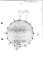
[0035] Figura 3 mostra uma configuração de acordo com a invenção para aplicar uma corrente e para medir um potencial diferencial empregando um cinto de eletrodos com 32 eletrodos;[0035] Figure 3 shows a configuration according to the invention to apply a current and to measure a differential potential using an electrode belt with 32 electrodes;
[0036] Figura 4 mostra um detalhe de uma configuração de acordo com a invenção com 32 eletrodos cercando uma seção do corpo com resistividade homogênea;[0036] Figure 4 shows a detail of a configuration according to the invention with 32 electrodes surrounding a body section with homogeneous resistivity;
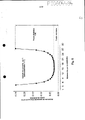
[0037] Figura 5 mostra um caso típico de medições de potencial diferencial em um tanque simulando um tórax humano de acordo com o estado da técnica;[0037] Figure 5 shows a typical case of differential potential measurements in a tank simulating a human thorax according to the state of the art;
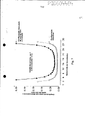
[0038] Figura 6 mostra um caso típico de medições de potencial diferencial de acordo com a invenção;[0038] Figure 6 shows a typical case of differential potential measurements according to the invention;
[0039] Figura 7 mostra uma comparação das medições de sinais de potencial diferencial entre uma configuração de acordo com o estado da técnica como mostrada na Figura 5 e uma configuração de acordo com a invenção como mostrada na Figura 6;[0039] Figure 7 shows a comparison of differential potential signal measurements between a configuration according to the prior art as shown in Figure 5 and a configuration according to the invention as shown in Figure 6;
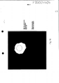
[0040] Figura 8 mostra uma ilustração de um modelo de tanque salino e um objeto não condutivo colocado nele a ser usado dentro da simulação;[0040] Figure 8 shows an illustration of a saline tank model and a non-conductive object placed in it to be used within the simulation;
[0041] Figura 9 mostra o resultado de uma reconstrução de imagem usando uma configuração adjacente e um algoritmo de retroprojeção;[0041] Figure 9 shows the result of an image reconstruction using an adjacent configuration and a backprojection algorithm;
[0042] Figura 10 mostra o resultado de uma reconstrução de imagem usando uma configuração de acordo com a invenção com um eletrodo se achando entre os pares aplicadores de corrente/pares de medição e um algoritmo de retroprojeção;[0042] Figure 10 shows the result of an image reconstruction using a configuration according to the invention with an electrode lying between the current applicator pairs/measurement pairs and a backprojection algorithm;
[0043] Figura 11 mostra o resultado de uma reconstrução de imagem usando uma configuração de acordo com a invenção com três eletrodos se achando entre os pares aplicadores de corrente/pares de medição e um algoritmo de retroprojeção;[0043] Figure 11 shows the result of an image reconstruction using a configuration according to the invention with three electrodes lying between the current applicator pairs/measurement pairs and a backprojection algorithm;
[0044] Figura 12 mostra o resultado de uma reconstrução de imagem usando uma configuração adjacente e um algoritmo de reconstrução baseado nos cálculos de matriz de sensibilidade para um modelo de malha de elemento finito; e[0044] Figure 12 shows the result of an image reconstruction using an adjacent configuration and a reconstruction algorithm based on sensitivity matrix calculations for a finite element mesh model; and
[0045] Figura 13 mostra o resultado de uma reconstrução de imagem usando uma configuração de acordo com a invenção com um eletrodo se achando entre os pares aplicadores de corrente/pares de medição e um algoritmo de reconstrução baseado nos cálculos de matriz de sensibilidade para um modelo de malha de elemento finito.[0045] Figure 13 shows the result of an image reconstruction using a configuration according to the invention with an electrode lying between the current applicator pairs/measurement pairs and a reconstruction algorithm based on sensitivity matrix calculations for a finite element mesh model.
[0046] Figura 1 mostra a configuração adjacente para aplicar uma corrente e para medir um potencial diferencial de acordo com o estado da técnica usando 16 eletrodos. Descrita é uma vista de seção transversal de um objeto de teste no plano de um cinto de eletrodos. Figura 1 mostra uma configuração adjacente para aplicar uma corrente e para medir um potencial diferencial.[0046] Figure 1 shows the adjacent configuration to apply a current and to measure a differential potential according to the state of the art using 16 electrodes. Depicted is a cross-sectional view of a test object in the plane of an electrode belt. Figure 1 shows an adjacent setup for applying a current and for measuring a differential potential.
[0047] Uma fonte de corrente de saída alta é aplicada por eletrodos 1 e 2, enquanto a diferença do potencial entre outros pares de eletrodos é medida - para simplificar assuntos, só o potencial diferencial oposto, isto é, entre eletrodos 9 e 10, é descrito. O potencial diferencial oposto corresponde normalmente ao mais baixo.[0047] A high output current source is applied by
[0048] Figura 2 mostra a mesma configuração como Figura 1, mas ilustra que, quando o número de eletrodos dobra a 32 eletrodos, enquanto mantendo a configuração adjacente, a distância entre eletrodos 1 e 2 encurta, aumentando a corrente de derivação pela pele entre estes eletrodos. Como resultado, densidade de corrente diminui no lado oposto do corpo, diminuindo gradientes de potencial. A distância separando o par de medição oposto, isto é, eletrodos 17 e 18, também se torna menos, diminuindo ademais os gradientes de potencial.[0048] Figure 2 shows the same configuration as Figure 1, but illustrates that when the number of electrodes doubles to 32 electrodes, while maintaining the adjacent configuration, the distance between
[0049] Figura 3 mostra uma configuração de acordo com a invenção para aplicar uma corrente e para medir um potencial diferencial empregando um cinto de eletrodos com 32 eletrodos. Um padrão de corrente é descrito, onde eletrodos de excitação e de retorno são eletrodos 1 e 3, respectivamente. O padrão de corrente subsequente ocorreria, usando eletrodos 2 e 4 para aplicação de corrente, e assim por diante. Apesar do uso de 32 eletrodos, os gradientes de potencial diferenciais medidos são semelhantes àqueles na Figura 1. Densidade de corrente é mais alta no lado oposto do corpo, e a distância dentro de pares de medição aumenta. Há alguma sobreposição espacial de informação, que pode ser considerada facilmente pelo algoritmo de reconstrução. Porém, cada potencial diferencial é uma informação independente, e há informação muito mais independente para a reconstrução de imagem nesta configuração do que em uma configuração de 16 eletrodos. Portanto, a resolução de imagem é melhor do que na Figura 1, enquanto a relação de sinal para ruído é melhor do que na Figura 2.[0049] Figure 3 shows a configuration according to the invention to apply a current and to measure a differential potential using an electrode belt with 32 electrodes. A current pattern is described, where excitation and return electrodes are
[0050] De acordo com uma realização preferida da invenção, todas as medições de potenciais diferenciais são executadas simultaneamente. Possíveis movimentos do corpo e/ou mudanças na impedância dentro do corpo durante as medições que estão acontecendo reduzirá a qualidade da imagem de tomografia de impedância elétrica. É, portanto, desejável reduzir o tempo requerido para as medições de potencial diferencial para um dado padrão de corrente. Executar as medições de potencial diferencial simultaneamente conduz ao possível tempo de medição mais curto e consequentemente às melhores condições de medição. Além disso, uma única fonte de corrente bipolar é usada preferivelmente para aplicar a corrente a cada par de eletrodos selecionados para aplicar corrente. Esta fonte de corrente com alta impedância de saída é multiplexada entre todo os possíveis pares de eletrodos. Comparado a sistemas usando uma fonte de corrente em cada par de eletrodos empregados para aplicar corrente, reduzirá ademais o ruído no sistema.[0050] According to a preferred embodiment of the invention, all measurements of differential potentials are performed simultaneously. Possible body movements and/or changes in impedance within the body while measurements are taking place will reduce the quality of the electrical impedance tomography image. It is therefore desirable to reduce the time required for differential potential measurements for a given current pattern. Carrying out the differential potential measurements simultaneously leads to the shortest possible measurement time and consequently the best measurement conditions. In addition, a single bipolar current source is preferably used to apply current to each pair of electrodes selected to apply current. This current source with high output impedance is multiplexed between all possible pairs of electrodes. Compared to systems using a current source in each pair of electrodes employed to apply current, it will further reduce the noise in the system.
[0051] Figura 4 mostra um detalhe de uma realização de acordo com a invenção com 32 eletrodos cercando uma seção do corpo com resistividade homogênea. Os eletrodos para aplicar uma corrente são 1 e 3 no lado oposto do corpo. Linhas isopotenciais conectando o dipolo formado entre eletrodos 1 e 3 e eletrodos 12 e 14 são descritas. Pode ser observado que há alguma sobreposição espacial de informação levada pelos potenciais diferenciais medidos por amplificadores 16 e 17, respectivamente, que deve ser considerado pelo algoritmo de reconstrução. Qualquer perturbação de impedância ocorrendo na região sobreposta causará uma mudança simultânea nos potenciais diferenciais medidos por amplificadores 16 e 17.[0051] Figure 4 shows a detail of an embodiment according to the invention with 32 electrodes surrounding a body section with homogeneous resistivity. Electrodes for applying a current are 1 and 3 on the opposite side of the body. Isopotential lines connecting the dipole formed between
[0052] Figura 5 mostra um caso típico de medições de potencial diferencial em um tanque simulando um tórax humano, com uma configuração adjacente de 32 eletrodos de acordo com o estado da técnica. Para simplificar assuntos, as medições de potencial diferencial correspondendo a pares 32-1, 12, e 2-3 não são descritas.[0052] Figure 5 shows a typical case of differential potential measurements in a tank simulating a human chest, with an adjacent configuration of 32 electrodes according to the state of the art. To simplify matters, the differential potential measurements corresponding to pairs 32-1, 12, and 2-3 are not described.
[0053] Figura 6 mostra um caso típico de medições de potencial diferencial no mesmo tanque como na Figura 5, com a mesma fonte de corrente e intensidade, usando uma configuração de 32 eletrodos de acordo com a invenção. Para simplificar assuntos, medições correspondendo a pares de eletrodos 31-1, 32-2, 1-3, 2-4 e 3-5 não são mostradas.[0053] Figure 6 shows a typical case of differential potential measurements in the same tank as in Figure 5, with the same current source and intensity, using a 32-electrode configuration according to the invention. To simplify matters, measurements corresponding to electrode pairs 31-1, 32-2, 1-3, 2-4 and 3-5 are not shown.
[0054] Figura 7 mostra uma comparação das medições de sinais de potencial diferencial entre uma realização de acordo com o estado da técnica como mostrada na Figura 5 e uma realização de acordo com a invenção como mostrada na Figura 6. Figura 7 mostra o aumento em sinais de potencial diferencial até quádruplo, que normalmente causas uma melhoria na relação de sinal para ruído pela mesma ordem de magnitude. Uma vantagem adicional da realização de acordo com a invenção está relacionada à gama dinâmica de potenciais diferenciais, que diminuíram quase o dobro, melhorando potencialmente a qualidade do processo de demodulação digital. Figura 8 mostra uma ilustração de um modelo de tanque salino e um objeto não condutivo colocado nele a ser usado dentro das simulações seguintes. Uma solução fisiológica com composição de 0,9% de NaC1 era usada e a fonte de corrente aplicava 0,1 mA a 125 kHz. Esta instalação resultou em um ruído aleatório quase constante em todos os canais com um desvio-padrão de cerca de 0,01 mV. Um cilindro de acrílico, com 4,5 cm de diâmetro foi colocado na posição ilustrada, que está a meio caminho entre o centro e a borda.[0054] Figure 7 shows a comparison of differential potential signal measurements between an embodiment according to the prior art as shown in Figure 5 and an embodiment according to the invention as shown in Figure 6. Figure 7 shows the increase in up to quadruple differential potential signals, which typically causes an improvement in the signal-to-noise ratio by the same order of magnitude. An additional advantage of the embodiment according to the invention is related to the dynamic range of differential potentials, which decreased almost twice, potentially improving the quality of the digital demodulation process. Figure 8 shows an illustration of a saline tank model and a non-conductive object placed in it to be used within the following simulations. A physiological solution with a composition of 0.9% NaCl was used and the current source applied 0.1 mA at 125 kHz. This setup resulted in nearly constant random noise on all channels with a standard deviation of about 0.01 mV. An acrylic cylinder, 4.5 cm in diameter, was placed in the illustrated position, which is halfway between the center and the edge.
[0055] Figura 9 mostra o resultado de uma reconstrução de imagem do objeto não condutivo de acordo com a Figura 8 usando uma realização adjacente e um algoritmo de retroprojeção. O algoritmo de retroprojeção é explicado por exemplo em Santosa F. e Vogelius M., "A backprojection algorithm for electrical impedance imaging", SIAM, 50: 216-243, 1990. O contorno do objeto não condutivo original está sobreposto para ilustrar a. posição esperada do objeto na imagem. A relação de sinal para ruído nas tensões mais baixas era cerca de 40 dB.[0055] Figure 9 shows the result of an image reconstruction of the non-conductive object according to Figure 8 using an adjacent realization and a backprojection algorithm. The backprojection algorithm is explained for example in Santosa F. and Vogelius M., "A backprojection algorithm for electrical impedance imaging", SIAM, 50: 216-243, 1990. The outline of the original non-conductive object is superimposed to illustrate a. expected position of the object in the image. The signal-to-noise ratio at the lowest voltages was around 40 dB.
[0056] Figura 10 mostra o resultado de uma reconstrução de imagem usando uma realização de acordo com a invenção com um eletrodo se achando entre os pares aplicadores de corrente/pares de medição e um algoritmo de retroprojeção. A fonte de corrente e intensidade eram a mesma como na Figura 9, com o mesmo sistema e cabos, gerando exatamente o mesmo ruído de fundo. A relação de sinal para ruído melhorou quádruplo, com uma melhoria visível na qualidade de imagem.[0056] Figure 10 shows the result of an image reconstruction using an embodiment according to the invention with an electrode lying between current applicator pairs/measurement pairs and a backprojection algorithm. The current source and intensity were the same as in Figure 9, with the same system and cables, generating exactly the same background noise. The signal-to-noise ratio has improved fourfold, with a visible improvement in image quality.
[0057] Figura 11 mostra o resultado de uma reconstrução de imagem usando uma realização de acordo com a invenção com três eletrodos se achando entre os pares aplicadores de corrente/pares de medição e um algoritmo de retroprojeção. A fonte de corrente e intensidade eram a mesma como na Figura 9, com o mesmo sistema e cabos, gerando exatamente o mesmo ruído de fundo. A relação de sinal para ruído melhorou ademais, quando comparada à Figura 10, mas já há alguma deterioração no posicionamento de objeto e na resolução.[0057] Figure 11 shows the result of an image reconstruction using an embodiment according to the invention with three electrodes lying between current applicator pairs/measurement pairs and a backprojection algorithm. The current source and intensity were the same as in Figure 9, with the same system and cables, generating exactly the same background noise. The signal-to-noise ratio has improved further when compared to Figure 10, but there is already some deterioration in object positioning and resolution.
[0058] Figura 12 mostra o resultado de uma reconstrução de imagem usando uma configuração adjacente e um algoritmo de reconstrução baseado nos cálculos de matriz de sensibilidade para um modelo de malha de elemento finito. Este algoritmo de reconstrução é explicado por exemplo em Morucci J. P. et al., "A direct sensitivity matrix approach for fast reconstruction in electrical impedance tomography", 'Physiological Measurement", 15: A104 - A114, 1994. A fonte de corrente e intensidade eram a mesma como na Figura 9, com o mesmo sistema e cabos, gerando exatamente o mesmo ruído de fundo. Sob as condições particulares testadas, com um ruído aleatório constante pelos eletrodos, o algoritmo resultou em resolução espacial melhor e propagou menos ruído à imagem do que o algoritmo de retroprojeção.[0058] Figure 12 shows the result of an image reconstruction using an adjacent configuration and a reconstruction algorithm based on sensitivity matrix calculations for a finite element mesh model. This reconstruction algorithm is explained for example in Morucci J. P. et al., "A direct sensitivity matrix approach for fast reconstruction in electrical impedance tomography", 'Physiological Measurement", 15: A104 - A114, 1994. The current source and intensity were the same as in Figure 9, with the same system and cables, generating exactly the same background noise. Under the particular conditions tested, with a constant random noise by the electrodes, the algorithm resulted in better spatial resolution and propagated less noise to the image of the than the backprojection algorithm.
[0059] Figura 13 mostra o resultado de uma reconstrução de imagem usando uma realização de acordo com a invenção com um eletrodo se achando entre os pares aplicadores de corrente/pares de medição e um algoritmo de reconstrução baseado nos cálculos de matriz de sensibilidade para um modelo de malha de elemento finito. Novamente, ajustes de fonte de corrente e ruído de fundo foram mantidos constantes como na Figura 9.[0059] Figure 13 shows the result of an image reconstruction using an embodiment according to the invention with an electrode lying between the current applicator/measurement pairs and a reconstruction algorithm based on sensitivity matrix calculations for a finite element mesh model. Again, current source and background noise settings were kept constant as in Figure 9.
[0060] Quando comparado à Figura 12, ruído de imagem diminuiu e a resolução espacial melhorou. A razão para esta melhoria é a melhor relação de sinal para ruído em medições de potencial diferencial, sem perder a vantagem principal de um sistema de potencial diferencial com eletrodos aplicadores de corrente localizados comparativamente um perto do outro, isto é sua alta frequência espacial de excitação, conduzindo a um maior número de medições independentes.[0060] When compared to Figure 12, image noise has decreased and spatial resolution has improved. The reason for this improvement is the better signal-to-noise ratio in differential potential measurements, without losing the main advantage of a differential potential system with current-applying electrodes located comparatively close to each other, i.e. their high spatial excitation frequency. , leading to a greater number of independent measurements.
Claims (7)
Priority Applications (4)
| Application Number | Priority Date | Filing Date | Title |
|---|---|---|---|
| BRPI0604484-0A BRPI0604484B1 (en) | 2006-08-28 | 2006-08-28 | METHOD FOR PERFORMING DATA COLLECTION ON ELECTRODES PLACED ON A BODY |
| PCT/IB2007/003726 WO2008041127A2 (en) | 2006-08-28 | 2007-08-28 | Data collection for electrical impedance tomography |
| EP07858927.2A EP2073702B2 (en) | 2006-08-28 | 2007-08-28 | Data collection for electrical impedance tomography |
| US12/383,604 US8352016B2 (en) | 2006-08-28 | 2009-03-27 | Data collection for electrical impedance tomography |
Applications Claiming Priority (1)
| Application Number | Priority Date | Filing Date | Title |
|---|---|---|---|
| BRPI0604484-0A BRPI0604484B1 (en) | 2006-08-28 | 2006-08-28 | METHOD FOR PERFORMING DATA COLLECTION ON ELECTRODES PLACED ON A BODY |
Publications (2)
| Publication Number | Publication Date |
|---|---|
| BRPI0604484A BRPI0604484A (en) | 2008-04-22 |
| BRPI0604484B1 true BRPI0604484B1 (en) | 2022-09-27 |
Family
ID=39247102
Family Applications (1)
| Application Number | Title | Priority Date | Filing Date |
|---|---|---|---|
| BRPI0604484-0A BRPI0604484B1 (en) | 2006-08-28 | 2006-08-28 | METHOD FOR PERFORMING DATA COLLECTION ON ELECTRODES PLACED ON A BODY |
Country Status (4)
| Country | Link |
|---|---|
| US (1) | US8352016B2 (en) |
| EP (1) | EP2073702B2 (en) |
| BR (1) | BRPI0604484B1 (en) |
| WO (1) | WO2008041127A2 (en) |
Families Citing this family (18)
| Publication number | Priority date | Publication date | Assignee | Title |
|---|---|---|---|---|
| EP3287073A1 (en) | 2005-07-01 | 2018-02-28 | Impedimed Limited | Monitoring system |
| CA2609111C (en) | 2005-07-01 | 2016-10-18 | Scott Chetham | A method and apparatus for performing impedance measurements in accordance with determining an electrode arrangement using a displayed representation |
| US9724012B2 (en) | 2005-10-11 | 2017-08-08 | Impedimed Limited | Hydration status monitoring |
| JP5419861B2 (en) | 2007-04-20 | 2014-02-19 | インぺディメッド リミテッド | Impedance measuring apparatus and method |
| JP5542050B2 (en) | 2007-08-09 | 2014-07-09 | インぺディメッド リミテッド | Impedance measurement method and apparatus |
| US9615767B2 (en) | 2009-10-26 | 2017-04-11 | Impedimed Limited | Fluid level indicator determination |
| WO2011060497A1 (en) | 2009-11-18 | 2011-05-26 | Impedimed Limited | Signal distribution for patient-electrode measurements |
| US8700121B2 (en) | 2011-12-14 | 2014-04-15 | Intersection Medical, Inc. | Devices for determining the relative spatial change in subsurface resistivities across frequencies in tissue |
| TWI461180B (en) * | 2011-12-30 | 2014-11-21 | Univ Nat Chiao Tung | Method for improving imaging resolution of electrical impedance tomography |
| US8983578B2 (en) | 2012-02-27 | 2015-03-17 | General Electric Company | System and method for transducer placement in soft-field tomography |
| US9581627B2 (en) | 2012-05-21 | 2017-02-28 | General Electric Company | Method and system for tomographic imaging |
| CN102894961B (en) * | 2012-10-30 | 2014-04-09 | 中国人民解放军第四军医大学 | Electrical impedance tomography method of self-structuring background frame |
| US10357177B2 (en) | 2013-12-13 | 2019-07-23 | General Electric Company | Systems and methods for electrical impedance imaging |
| US10874324B2 (en) | 2015-10-20 | 2020-12-29 | General Electric Company | Detection of physiological changes in impedance monitoring |
| US20190298219A1 (en) * | 2016-12-02 | 2019-10-03 | Bilab Co., Ltd. | Electrode Belt Device for Measuring Bio-Signal |
| DE102017123034B4 (en) * | 2017-10-04 | 2023-10-26 | Krohne Messtechnik Gmbh | Method for calibrating a tomography device for electrical impedance tomography |
| US11412946B2 (en) * | 2017-11-14 | 2022-08-16 | Timpel Medical B.V. | Electrical impedance tomography device and system having a multi-dimensional electrode arrangement |
| CN111024772B (en) * | 2019-12-03 | 2022-06-14 | 西安科技大学 | Laser cladding molten pool micro-resistance distribution imaging method and device |
Family Cites Families (16)
| Publication number | Priority date | Publication date | Assignee | Title |
|---|---|---|---|---|
| GB8309927D0 (en) * | 1983-04-13 | 1983-05-18 | Smith D N | Determination of internal structure of bounded objects |
| US4920490A (en) * | 1988-01-28 | 1990-04-24 | Rensselaer Polytechnic Institute | Process and apparatus for distinguishing conductivities by electric current computed tomography |
| GB9013177D0 (en) * | 1990-06-13 | 1990-08-01 | Brown Brian H | Real-time imaging, etc. |
| US5272624A (en) * | 1990-10-02 | 1993-12-21 | Rensselaer Polytechnic Institute | Current patterns for impedance tomography |
| US5381333A (en) * | 1991-07-23 | 1995-01-10 | Rensselaer Polytechnic Institute | Current patterns for electrical impedance tomography |
| GB9226376D0 (en) † | 1992-12-18 | 1993-02-10 | British Tech Group | Tomography |
| DE4332257C2 (en) † | 1993-09-22 | 1996-09-19 | P Osypka Gmbh Medizintechnik D | Device for generating tomographic images |
| DE59811547D1 (en) † | 1997-07-25 | 2004-07-15 | Kaiser Werner Alois | ARRANGEMENT FOR DETECTION, FOR DIFFERENTIAL-DIAGNOSTIC CHARACTERIZATION AND FOR THE TREATMENT OF TUMORS |
| EP1410050A1 (en) * | 2001-06-15 | 2004-04-21 | Mississippi State University | Through-log density detector |
| DE10156833A1 (en) | 2001-11-20 | 2003-05-28 | Boehm Stephan | Electrode for biomedical measurements has contact plate connected to line driver high impedance input and current source current output, line driver, current source close to contact plate |
| CA2480430C (en) * | 2003-09-04 | 2013-11-05 | Adrian Nachman | Current density impedance imaging (cdii) |
| US20050107833A1 (en) * | 2003-11-13 | 2005-05-19 | Freeman Gary A. | Multi-path transthoracic defibrillation and cardioversion |
| EP1952764B1 (en) * | 2003-11-25 | 2010-05-05 | University-Industry Cooperation Group of Kyung Hee University | System and method for visualizing conductivity and current density distribution in object |
| WO2006044868A1 (en) * | 2004-10-20 | 2006-04-27 | Nervonix, Inc. | An active electrode, bio-impedance based, tissue discrimination system and methods and use |
| US20070083239A1 (en) * | 2005-09-23 | 2007-04-12 | Denise Demarais | Methods and apparatus for inducing, monitoring and controlling renal neuromodulation |
| DE102005031752B4 (en) * | 2005-07-07 | 2017-11-02 | Drägerwerk AG & Co. KGaA | Electroimpedance tomography device with common-mode signal suppression |
-
2006
- 2006-08-28 BR BRPI0604484-0A patent/BRPI0604484B1/en active IP Right Grant
-
2007
- 2007-08-28 WO PCT/IB2007/003726 patent/WO2008041127A2/en active Application Filing
- 2007-08-28 EP EP07858927.2A patent/EP2073702B2/en active Active
-
2009
- 2009-03-27 US US12/383,604 patent/US8352016B2/en active Active
Also Published As
| Publication number | Publication date |
|---|---|
| US20090234244A1 (en) | 2009-09-17 |
| EP2073702A2 (en) | 2009-07-01 |
| WO2008041127A2 (en) | 2008-04-10 |
| EP2073702B2 (en) | 2016-08-03 |
| BRPI0604484A (en) | 2008-04-22 |
| US8352016B2 (en) | 2013-01-08 |
| WO2008041127A3 (en) | 2008-07-17 |
| EP2073702B1 (en) | 2012-11-21 |
Similar Documents
| Publication | Publication Date | Title |
|---|---|---|
| BRPI0604484B1 (en) | METHOD FOR PERFORMING DATA COLLECTION ON ELECTRODES PLACED ON A BODY | |
| Harikumar et al. | Electrical impedance tomography (EIT) and its medical applications: a review | |
| US6397095B1 (en) | Magnetic resonance—electrical impedance tomography | |
| Kauppinen et al. | Sensitivity distribution visualizations of impedance tomography measurement strategies | |
| McEwan et al. | A review of errors in multi-frequency EIT instrumentation | |
| JP2012179352A (en) | System and method for constructing current dipole | |
| Gençer et al. | Forward problem solution of electromagnetic source imaging using a new BEM formulation with high-order elements | |
| Barber | Electrical impedance tomography | |
| Fischer et al. | Application of high-order boundary elements to the electrocardiographic inverse problem | |
| Kauppinen et al. | Sensitivity distribution simulations of impedance tomography electrode combinations | |
| Dimas et al. | Electrical impedance tomography image reconstruction for adjacent and opposite strategy using FEMM and EIDORS simulation models | |
| US20210137408A1 (en) | System and method for conductivity-based imaging | |
| BR112012005329A2 (en) | Apparatus for non-invasive intracardiac electrocardiography (ecg) by the use of a magnetic and conductive interference device, method for non-invasive intracardiac electrocardiography (ecg) by the use of an electrical and magnetic conduction interference device and a computer program | |
| CN106821380B (en) | Biomedical electrical impedance imaging method and device based on the regularization of multiplying property | |
| US20200188676A1 (en) | Bioimpedance measurement method and apparatus with electrical stimulation performance | |
| Brauer et al. | Reconstruction of extended current sources in a human body phantom applying biomagnetic measuring techniques | |
| US20230320608A1 (en) | Excitation response measurement method, electrical impedance tomography method, and storage medium | |
| Weiss et al. | The influence of fibre orientation, extracted from different segments of the human left ventricle, on the activation and repolarization sequence: a simulation study | |
| Bruder et al. | The influence of inhomogeneous volume conductor models on the ECG and the MCG | |
| Meeson et al. | The dependence of EIT images on the assumed initial conductivity distribution: a study of pelvic imaging | |
| Eyuboglu et al. | Problems of cardiac output determination from electrical impedance tomography scans | |
| Shishvan et al. | Practical implementation of a novel output impedance measurement technique for EIT system while attached to a load | |
| Sun et al. | A New Method for Electrical Impedance Tomography with Incomplete Electrode Array | |
| RU2790406C1 (en) | Method for diagnostics and control of treatment of cardiac pathologies | |
| Pesola | Cardiomagnetic source imaging |
Legal Events
| Date | Code | Title | Description |
|---|---|---|---|
| B25G | Requested change of headquarter approved |
Owner name: TIMPEL S.A. (BR/SP) |
|
| B25G | Requested change of headquarter approved |
Owner name: TIMPEL S.A. (BR/SP) |
|
| B07A | Application suspended after technical examination (opinion) [chapter 7.1 patent gazette] | ||
| B09B | Patent application refused [chapter 9.2 patent gazette] | ||
| B12B | Appeal against refusal [chapter 12.2 patent gazette] | ||
| B16A | Patent or certificate of addition of invention granted [chapter 16.1 patent gazette] |
Free format text: PRAZO DE VALIDADE: 20 (VINTE) ANOS CONTADOS A PARTIR DE 28/08/2006, OBSERVADAS AS CONDICOES LEGAIS. PATENTE CONCEDIDA CONFORME ADI 5.529/DF, QUE DETERMINA A ALTERACAO DO PRAZO DE CONCESSAO. |