BRPI0603262B1 - aircraft wing including a slat on the leading edge of the wing and a rigid fence attached to a structurally rigid non-movable portion of the wing - Google Patents
aircraft wing including a slat on the leading edge of the wing and a rigid fence attached to a structurally rigid non-movable portion of the wing Download PDFInfo
- Publication number
- BRPI0603262B1 BRPI0603262B1 BRPI0603262-1A BRPI0603262A BRPI0603262B1 BR PI0603262 B1 BRPI0603262 B1 BR PI0603262B1 BR PI0603262 A BRPI0603262 A BR PI0603262A BR PI0603262 B1 BRPI0603262 B1 BR PI0603262B1
- Authority
- BR
- Brazil
- Prior art keywords
- wing
- aircraft
- slat
- fence
- aerodynamic
- Prior art date
Links
Images


Classifications
-
- B—PERFORMING OPERATIONS; TRANSPORTING
- B64—AIRCRAFT; AVIATION; COSMONAUTICS
- B64C—AEROPLANES; HELICOPTERS
- B64C3/00—Wings
- B64C3/58—Wings provided with fences or spoilers
-
- B—PERFORMING OPERATIONS; TRANSPORTING
- B64—AIRCRAFT; AVIATION; COSMONAUTICS
- B64C—AEROPLANES; HELICOPTERS
- B64C23/00—Influencing air flow over aircraft surfaces, not otherwise provided for
- B64C23/06—Influencing air flow over aircraft surfaces, not otherwise provided for by generating vortices
-
- B—PERFORMING OPERATIONS; TRANSPORTING
- B64—AIRCRAFT; AVIATION; COSMONAUTICS
- B64C—AEROPLANES; HELICOPTERS
- B64C7/00—Structures or fairings not otherwise provided for
- B64C7/02—Nacelles
-
- B—PERFORMING OPERATIONS; TRANSPORTING
- B64—AIRCRAFT; AVIATION; COSMONAUTICS
- B64C—AEROPLANES; HELICOPTERS
- B64C9/00—Adjustable control surfaces or members, e.g. rudders
- B64C9/14—Adjustable control surfaces or members, e.g. rudders forming slots
- B64C9/22—Adjustable control surfaces or members, e.g. rudders forming slots at the front of the wing
- B64C9/24—Adjustable control surfaces or members, e.g. rudders forming slots at the front of the wing by single flap
-
- Y—GENERAL TAGGING OF NEW TECHNOLOGICAL DEVELOPMENTS; GENERAL TAGGING OF CROSS-SECTIONAL TECHNOLOGIES SPANNING OVER SEVERAL SECTIONS OF THE IPC; TECHNICAL SUBJECTS COVERED BY FORMER USPC CROSS-REFERENCE ART COLLECTIONS [XRACs] AND DIGESTS
- Y02—TECHNOLOGIES OR APPLICATIONS FOR MITIGATION OR ADAPTATION AGAINST CLIMATE CHANGE
- Y02T—CLIMATE CHANGE MITIGATION TECHNOLOGIES RELATED TO TRANSPORTATION
- Y02T50/00—Aeronautics or air transport
- Y02T50/10—Drag reduction
-
- Y—GENERAL TAGGING OF NEW TECHNOLOGICAL DEVELOPMENTS; GENERAL TAGGING OF CROSS-SECTIONAL TECHNOLOGIES SPANNING OVER SEVERAL SECTIONS OF THE IPC; TECHNICAL SUBJECTS COVERED BY FORMER USPC CROSS-REFERENCE ART COLLECTIONS [XRACs] AND DIGESTS
- Y02—TECHNOLOGIES OR APPLICATIONS FOR MITIGATION OR ADAPTATION AGAINST CLIMATE CHANGE
- Y02T—CLIMATE CHANGE MITIGATION TECHNOLOGIES RELATED TO TRANSPORTATION
- Y02T50/00—Aeronautics or air transport
- Y02T50/30—Wing lift efficiency
Abstract
DISPOSITIVO AERODINÂMICO PARA MELHORIA DO COEFICIENTE DE SUSTENTAÇÃO Descreve-se um dispositivo aerodinâmico do tipo fence (F) rigidamente instalado ao bordo de ataque da asa (W) de uma aeronave, próximo a um slat (S) porém sem estar fixado a ele,de modo que quando o slat (S) deflete, ou exerce qualquer movimento, o fence (F) permanece imovel, fixo em sua posição no bordo de ataque da asa (W) ; o fence (F) provoca um vórtice aerodinâmico que atua no extradorso (região superior da asa), o qual permite a existência de um gradiente adverso de pressão mais forte, sem que haja deslocamento aerodinâmico, com efeito benéfico no extradorso da asa, de modo a que o dito vórtice permita que porções de ar do escoamento não perturbado (região mais afastada da superfície externa da aeronave, sobre a asa ) sejam trazidas para próximo da superfície da asa (região mais próxima à superfície da aeronave, sobre a asa), alterando favoravelmente o perfil da camada limite da região (Z) , tornando-a mais resistente ao deslocamento aerodinâmico, favorecendo a operação da aeronave em baixas velocidades.AERODYNAMIC DEVICE FOR IMPROVING THE SUPPORT COEFFICIENT An aerodynamic device of the type fence (F) rigidly installed on the leading edge of the wing (W) of an aircraft, close to a slat (S) but without being attached to it, is described. so that when the slat (S) deflects, or exerts any movement, the fence (F) remains immobile, fixed in its position on the leading edge of the wing (W); the fence (F) causes an aerodynamic vortex that acts on the extrados (upper wing region), which allows the existence of a stronger adverse pressure gradient, without any aerodynamic displacement, with a beneficial effect on the extrados of the wing, in a way that said vortex allows portions of air from the undisturbed flow (region furthest from the outside surface of the aircraft, on the wing) to be brought close to the surface of the wing (region closest to the surface of the aircraft, on the wing), favorably altering the profile of the boundary layer of the region (Z), making it more resistant to aerodynamic displacement, favoring the operation of the aircraft at low speeds.
Description
[001] A presente invenção trata de uma asa de aeronave incluindo um slat no bordo de ataque da asa e um fencerígido preso a uma porção estruturalmente rígida não móvel da asa para a melhoria do desempenho da aeronave a baixas velocidades.[001] The present invention deals with an aircraft wing including a slat on the leading edge of the wing and a fencerígeno attached to a structurally rigid non-moving portion of the wing to improve the aircraft's performance at low speeds.
[002] Em uma missão típica, uma aeronave pode operar em várias velocidades, conforme a fase dessa missão. Na fase de cruzeiro, opera-se em velocidades altas. Em situação, por exemplo, de decolagem, subida e holding (situação em que a aeronave aguarda para ter permissão para pouso), opera-se em velocidades intermediárias. A fase de pouso é aquela em que tipicamente a aeronave opera na velocidade mais baixa. É desejável que uma aeronave opere eficientemente também em baixas velocidades, pois isso permite que a aeronave pouse em condições mais seguras, além de ser mais fácil homologá-la para pousar num maior número de pistas (já que ela consegue pousar em velocidades baixas, poderá fazê-lo também nas pistas mais curtas).[002] In a typical mission, an aircraft can operate at various speeds, depending on the phase of that mission. In the cruising phase, it operates at high speeds. In a situation, for example, of takeoff, climb and holding (situation in which the aircraft waits to be allowed to land), it operates at intermediate speeds. The landing phase is one in which the aircraft typically operates at the lowest speed. It is desirable for an aircraft to operate efficiently also at low speeds, as this allows the aircraft to land in safer conditions, in addition to making it easier to approve it to land on a larger number of runways (since it can land at low speeds, it may do it also on the shortest tracks).
[003] À medida que se diminui a velocidade de operação, porém, pode ser verificada uma degradação aerodinâmica na asa que prejudica a sua capacidade de produzir sustentação. Encontram-se na literatura dispositivos aerodinâmicos cuja função é retardar o aparecimento dessa degradação e permitir que a aeronave possa operar com segurança a baixas velocidades. Geradores de vórtice fixos ao bordo de ataque da asa, fencesaerodinâmicos e vortilonssão exemplos desses dispositivos.[003] As the speed of operation decreases, however, an aerodynamic degradation in the wing can be verified that impairs its ability to produce lift. Aerodynamic devices are found in the literature whose function is to delay the appearance of this degradation and allow the aircraft to operate safely at low speeds. Vortex generators attached to the leading edge of the wing, fencesaerodynamics and vortilons are examples of these devices.
[004] A patente US 6,152,404 de 28/11/2.000, intitulada “Apparatus for influencing a wing root airflow in an aircraft”, a qual trata de detalhes de dispositivos aerodinâmicos do tipo fence, descreve explicitamente, para o fence com a função em questão, que o dito dispositivo aerodinâmico (fence) deve ser preso ao slat no bordo de ataque da asa da aeronave, acompanhando-o quando este deflete, e não pode jamais estar em outra posição. Neste mesmo documento US 6,152,404, cogita-se até em pequenas mudanças na geometria do fence, mas ele permanece sempre preso ao slat.[004] US patent 6,152,404 of 11/28/2000, entitled “Apparatus for influencing a wing root airflow in an aircraft”, which deals with details of aerodynamic devices of the fence type, explicitly describes, for the fence with the function in question, that said aerodynamic device (fence) must be attached to the slat on the leading edge of the aircraft wing, accompanying it when it deflects, and can never be in another position. In this same document US 6,152,404, it is contemplated even in small changes in the geometry of the fence, but it always remains attached to the slat.
[005] A invenção será sucintamente descrita com base nas figuras, onde:[005] The invention will be briefly described based on the figures, where:
[006] A figura 1 exibe uma vista em perspectiva, em detalhe, de geradores de vórtices fixos ao longo do bordo de ataque da asa de uma aeronave, conforme o estado da técnica já conhecida;[006] Figure 1 shows a perspective view, in detail, of fixed vortex generators along the leading edge of an aircraft's wing, according to the state of the art already known;
[007] A figura 2 ilustra geradores de vórtices fixos à fuselagem de uma aeronave, na região do cockpit, também pertencente ao estado da técnica conhecida;[007] Figure 2 illustrates vortex generators attached to the fuselage of an aircraft, in the cockpit region, also belonging to the state of the art known;
[008] A figura 3 mostra uma vista em perspectiva frontal, em detalhe, da carenagem do motor de uma aeronave, onde um tipo de fenceaerodinâmico do estado da técnica está instalado, para manter a qualidade do escoamento na asa;[008] Figure 3 shows a frontal perspective view, in detail, of an aircraft's engine fairing, where a state-of-the-art fenceaerodynamic type is installed, to maintain the quality of the flow in the wing;
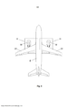
[009] A figura 4 mostra a planta superior de uma aeronave exemplificativa, com a indicação de uma região em detalhe H;[009] Figure 4 shows the top plan of an exemplary aircraft, with the indication of a region in detail H;
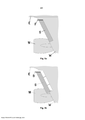
[010] A figura 5a exibe uma vista superior, em detalhe, de um dispositivo aerodinâmico do tipo fence fixo ao slat, que se encontra fechado, correspondendo às soluções encontradas no estado da técnica. Esta figura corresponde a uma ampliação na região H esquematizado na figura 4;[010] Figure 5a shows a top view, in detail, of an aerodynamic device of the fence type fixed to the slat, which is closed, corresponding to the solutions found in the state of the art. This figure corresponds to an enlargement in the region H shown in figure 4;
[011] A figura 5b ilustra uma vista superior, em detalhe, do dispositivo aerodinâmico do tipo fence do estado da técnica, fixo ao slat, que agora está na posição defletida (estendida). Esta figura corresponde a uma ampliação na região H esquematizado na figura 4;[011] Figure 5b illustrates a top view, in detail, of the state of the art aerodynamic fence device, attached to the slat, which is now in the deflected (extended) position. This figure corresponds to an enlargement in the region H shown in figure 4;
[012] A figura 6 representa uma vista em perspectiva, em detalhe, mostrando a posição do fence da presente invenção, próximo à fuselagem, com o slat em posição recolhida, no bordo de ataque da asa de uma aeronave;[012] Figure 6 represents a perspective view, in detail, showing the position of the fence of the present invention, close to the fuselage, with the slat in a retracted position, on the leading edge of an aircraft wing;
[013] A figura 7 exibe um esquema em três vistas, em detalhe, do posicionamento do fence da presente invenção, com slat em posição recolhida, na aeronave exemplificativa;[013] Figure 7 shows a scheme in three views, in detail, of the positioning of the fence of the present invention, with slat in a retracted position, in the exemplary aircraft;
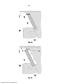
[014] A figura 8a apresenta uma vista superior, em detalhe, do dispositivo aerodinâmico do tipo fence pertencente à invenção, o qual não é fixo ao slat e sim ao bordo de ataque da asa; nesta vista, o slat se encontra na posição fechada;[014] Figure 8a shows a top view, in detail, of the aerodynamic device of the fence type belonging to the invention, which is not fixed to the slat but to the leading edge of the wing; in this view, the slat is in the closed position;
[015] A figura 8b ilustra uma vista superior, em detalhe, do dispositivo aerodinâmico do tipo fence da presente invenção, com uma linha traço-ponto indicando uma região de corte X-X; nota-se que o slatestá, agora, na posição defletida (estendida);[015] Figure 8b illustrates a top view, in detail, of the aerodynamic fence-type device of the present invention, with a dash-point line indicating an X-X cut region; note that the slat is now in the deflected (extended) position;
[016] A figura 9 mostra uma vista lateral da asa, segundo a região de corte X-X indicada na figura 10;[016] Figure 9 shows a side view of the wing, according to the X-X section indicated in figure 10;
[017] A figura 10 ilustra uma vista em perspectiva, em detalhe, de uma aeronave equipada com o dispositivo aerodinâmico fence da presente invenção no bordo de ataque da asa, onde está representado graficamente o vórtice formado no dito fence.[017] Figure 10 illustrates a perspective view, in detail, of an aircraft equipped with the aerodynamic fence device of the present invention at the leading edge of the wing, where the vortex formed in said fence is represented graphically.
[018] O novo dispositivo aerodinâmico da invenção será referido aqui como fenceaerodinâmico, e sua função é permitir que a aeronave possa operar com mais segurança em condições de baixa velocidade, como pouso. Este fence gera um vórtice aerodinâmico que passa sobre a asa, conferindo características desejáveis ao escoamento nesta região. À medida que se aumenta o ângulo de ataque de operação de uma aeronave em vôo, a medição das distribuições de pressão mostra que os gradientes adversos de pressão no extradorso da asa aumentam na recuperação da pressão até o bordo de fuga. Isso torna o escoamento nesta região mais propenso a sofrer descolamento aerodinâmico. Com o início do descolamento aerodinâmico, verifica-se o início da dificuldade de se produzir sustentação, o que é indesejável para a aeronave.[018] The new aerodynamic device of the invention will be referred to here as fenceaerodynamic, and its function is to allow the aircraft to operate more safely in low speed conditions, such as landing. This fence generates an aerodynamic vortex that passes over the wing, giving desirable characteristics to the flow in this region. As the operating angle of attack of an aircraft in flight is increased, the measurement of pressure distributions shows that adverse pressure gradients in the wing's wing increase in pressure recovery to the trailing edge. This makes the flow in this region more likely to undergo aerodynamic detachment. With the beginning of aerodynamic detachment, the difficulty of producing lift occurs, which is undesirable for the aircraft.
[019] Geradores de vórtice fixos (V) ao longo do bordo de ataque da asa (W), conforme mostra a figura 1, pertencem ao estado da técnica conhecida. Também são já conhecidos os geradores de vórtice (V) dispostos sobre a fuselagem de uma aeronave, tal como na região do cockpit, conforme está ilustrado na figura 2, os quais têm efeito de evitar descolamento aerodinâmico no cockpit da aeronave, não tendo como função primordial auxiliar na sustentação.[019] Fixed vortex generators (V) along the leading edge of the wing (W), as shown in figure 1, belong to the state of the art. Also known are the vortex generators (V) arranged on the fuselage of an aircraft, as in the cockpit region, as shown in figure 2, which have the effect of preventing aerodynamic detachment in the aircraft cockpit, having no function primordial auxiliary in the support.
[020] A figura 3 está mostrando um tipo de fenceaerodinâmico (B) do estado da técnica, o qual está posicionado junto à carenagem do motor (turbina) (M) de uma aeronave, para manter uma boa qualidade de escoamento de ar na asa (W).[020] Figure 3 is showing a type of fenceaerodynamic (B) of the state of the art, which is positioned next to the engine (turbine) fairing (M) of an aircraft, to maintain a good quality of air flow in the wing (W).
[021] Na figura 4, observa-se, (circundado em linha tracejada) a posição do fenceaerodinâmico da presente invenção, no bordo de ataque da asa (W), próximo à fuselagem (E), com o slat do bordo de ataque em posição recolhida.[021] In figure 4, it is observed (surrounded by a dashed line) the position of the fenceaerodynamic of the present invention, on the leading edge of the wing (W), close to the fuselage (E), with the leading edge slat in collapsed position.
[022] A figura 5a mostra uma vista superior de um dispositivo aerodinâmico (B) do tipo fence, correspondendo a uma solução anteriormente conhecida; o fence (B) é fixo ao slat (S) que, nesta figura, se encontra na posição fechada. Já na figura 5b observa-se o mesmo fence (B) fixo ao slat (S), porém este agora está na posição defletida (estendida); portanto, conforme o que já se conhece no estado da técnica, o fence (B) acompanha o movimento do slat (S). É esta a diferença básica entre o fence (B), já conhecido, e o novo fence adotado pela presente invenção.[022] Figure 5a shows a top view of an aerodynamic device (B) of the fence type, corresponding to a previously known solution; the fence (B) is fixed to the slat (S) which, in this figure, is in the closed position. Figure 5b shows the same fence (B) fixed to the slat (S), but this is now in the deflected (extended) position; therefore, according to what is already known in the state of the art, the fence (B) follows the movement of the slat (S). This is the basic difference between the fence (B), already known, and the new fence adopted by the present invention.
[023] Do ângulo da figura 4, não há diferença visual entre a proposta da presente invenção e aquela com a mesma função, existente no estado da arte, elucidada na figura 5, se ambos os slats estiverem em posição recolhida.[023] From the angle of figure 4, there is no visual difference between the proposal of the present invention and the one with the same function, existing in the state of the art, elucidated in figure 5, if both slats are in a retracted position.
[024] Para melhor clareza de visualização, a figura 4 mostra a planta superior de uma aeronave exemplificativa, com a indicação de regiões em detalhe (H), cada uma circundada por um quadrado em linha cheia, mostrando a região de localização do fence (F) da presente invenção (não mostrado), onde a instalação de um ou mais fences (F) é simétrica para ambas as asas (W) da aeronave. Note-se a proximidade com a fuselagem (E), e com os motores (M), conforme pode ser visto nas figuras 7a, 7b e 7c as quais exibem um esquema em três vistas do posicionamento do fence (F) na aeronave. A figura 7a mostra uma vista de perfil da asa (W), a figura 7b uma vista superior da asa da aeronave, e a figura 7c uma vista frontal da aeronave.[024] For better visual clarity, figure 4 shows the top plan of an exemplary aircraft, with the indication of regions in detail (H), each surrounded by a square in full line, showing the region where the fence is located ( F) of the present invention (not shown), where the installation of one or more fences (F) is symmetrical to both wings (W) of the aircraft. Note the proximity to the fuselage (E), and to the engines (M), as can be seen in figures 7a, 7b and 7c which show a diagram in three views of the positioning of the fence (F) on the aircraft. Figure 7a shows a profile view of the wing (W), figure 7b a top view of the aircraft wing, and figure 7c a front view of the aircraft.
[025] A figura 8 apresenta uma vista superior do dispositivo aerodinâmico do tipo fence (F) pertencente à invenção, o qual não é fixo ao slat (S) e sim ao bordo de ataque da asa (W); na figura 8a, o slat (S) se encontra na posição fechada. A figura 8b ilustra o mesmo fence (F), porém com o slat (S) agora, na posição defletida (estendida). Observa-se também uma linha traço- ponto indicando uma região de corte X-X, região esta mostrada pela figura 9.[025] Figure 8 shows a top view of the aerodynamic fence type device (F) belonging to the invention, which is not fixed to the slat (S) but to the leading edge of the wing (W); in figure 8a, the slat (S) is in the closed position. Figure 8b illustrates the same fence (F), but with the slat (S) now, in the deflected (extended) position. There is also a dash-point line indicating an X-X cut region, the region shown in figure 9.
[026] Na figura 9, que corresponde a uma vista lateral da asa (W), a região de corte X-X permite visualizar o slat (S) defletido, evidenciando o fato do fence (F) ser fixo ao bordo de ataque da asa (W). Note-se também a forma laminar, com contorno arredondado, suave, do dito fence.[026] In figure 9, which corresponds to a side view of the wing (W), the cut region XX allows to see the deflected slat (S), showing the fact that the fence (F) is fixed to the leading edge of the wing ( W). Note also the laminar shape, with a smooth, rounded outline, of the said fence.
[027] O fenceaerodinâmico (F) da presente invenção provoca um vórtice aerodinâmico que atua no extradorso (região superior da asa), o qual permite a existência de um gradiente adverso de pressão mais forte, sem que haja descolamento aerodinâmico, com efeito benéfico no extradorso da asa.[027] The fenceaerodynamic (F) of the present invention causes an aerodynamic vortex that acts on the extrados (upper wing region), which allows the existence of a stronger adverse pressure gradient, without any aerodynamic detachment, with a beneficial effect on the wing extraction.
[028] Quando há escoamento aerodinâmico, nota-se a formação de uma camada limite ao longo de toda a superfície do avião. A proximidade da fuselagem com a asa provoca a confluência de duas camadas-limites, uma no extradorso da asa e outra na carenagem asa-fuselagem, o que torna a camada- limite do fluxo de ar resultante nesta região mais espessa e mais propensa a sofrer descolamento aerodinâmico. O fence da presente invenção mostrou-se uma solução eficiente contra os problemas devidos à referida confluência na região próxima à interseção asa-fuselagem.[028] When there is aerodynamic flow, the formation of a boundary layer is noted over the entire surface of the plane. The proximity of the fuselage to the wing causes the confluence of two boundary layers, one on the wing's outer edge and the other on the wing-fuselage fairing, which makes the resulting airflow boundary layer in this region thicker and more likely to suffer aerodynamic detachment. The fence of the present invention proved to be an efficient solution against the problems due to the referred confluence in the region close to the wing-fuselage intersection.
[029] A figura 10 ilustra uma vista em perspectiva de uma aeronave equipada com o dispositivo aerodinâmico fence (F) da invenção no bordo de ataque da asa (W), onde as linhas (A) representam graficamente o vórtice formado sobre a asa (W) no dito fence. O vórtice permite que porções de ar do escoamento não perturbado (região Y sobre a asa, mais próxima do bordo de ataque) sejam trazidas para próximo da superfície da asa (região Z sobre a asa, mais próxima do bordo de fuga). Isto altera favoravelmente o perfil da camada limite na região (Z), tornando-a mais resistente ao descolamento aerodinâmico. Dessa forma, a aeronave resiste a ângulos de ataque maiores sem sofrer “stall” (sem estolar), o que confere a ela, por exemplo, melhor característica de pouso. É importante frisar que a efetividade desse dispositivo aerodinâmico é verificada apenas quando o slat (S) está em posição defletida, conforme a figura 10 está mostrando. O fence (F) com este elemento (slat) recolhido não tem função para o caso da presente invenção.[029] Figure 10 illustrates a perspective view of an aircraft equipped with the aerodynamic fence device (F) of the invention at the leading edge of the wing (W), where the lines (A) graphically represent the vortex formed over the wing ( W) in said fence. The vortex allows portions of air from the undisturbed flow (region Y on the wing, closest to the leading edge) to be brought close to the surface of the wing (region Z on the wing, closest to the trailing edge). This favorably alters the profile of the boundary layer in the region (Z), making it more resistant to aerodynamic detachment. In this way, the aircraft resists greater angles of attack without suffering a stall (without stalling), which gives it, for example, a better landing characteristic. It is important to note that the effectiveness of this aerodynamic device is checked only when the slat (S) is in a deflected position, as shown in figure 10. The fence (F) with this element (slat) retracted has no function in the case of the present invention.
[030] O fence (F) da presente invenção foi desenvolvido e sofreu diversos ensaios em túnel de vento, comprovando seu funcionamento e alta eficiência, aperfeiçoando significativamente o desempenho da aeronave em baixas velocidades; particularmente, houve melhora significativa do coeficiente de sustentação máximo em relação aos esquemas usando os fences (B) conhecidos do estado da técnica. Inclusive, foram feitos ensaios de túnel de vento da mesma aeronave sem fences, com o fence (B) na posição já conhecida (Figuras 5a e 5b), preso ao slat (S), e com o fence (F) na posição proposta nesta invenção (Figs. 8a e 8b). Usando o fence (F) da invenção, a melhora percentual do coeficiente de sustentação em relação às soluções já conhecidas (fence B) é equivalente à melhora desta em relação à configuração sem fences.[030] The fence (F) of the present invention was developed and underwent several tests in a wind tunnel, proving its operation and high efficiency, significantly improving the performance of the aircraft at low speeds; in particular, there was a significant improvement in the maximum lift coefficient compared to the schemes using the fences (B) known from the prior art. In fact, wind tunnel tests were performed on the same aircraft without fences, with the fence (B) in the already known position (Figures 5a and 5b), attached to the slat (S), and with the fence (F) in the position proposed in this invention (Figs. 8a and 8b). Using the fence (F) of the invention, the percentage improvement of the support coefficient in relation to the already known solutions (fence B) is equivalent to the improvement of this in relation to the configuration without fences.
[031] Como visto, o fence (F) da presente invenção não é fixo numa parte móvel; fixá-lo numa parte móvel exigiria um sistema mecânico móvel de apoio que fosse estruturalmente forte para suportar o aparato e as cargas aerodinâmicas que eventualmente existissem. Isto tornaria o sistema desnecessariamente mais pesado e complexo. A fixação no corpo da aeronave é bem mais simples e exige bem menos reforço estrutural.[031] As seen, the fence (F) of the present invention is not fixed to a moving part; fixing it to a moving part would require a mobile mechanical support system that was structurally strong to support the apparatus and any aerodynamic loads that might exist. This would make the system unnecessarily cumbersome and complex. Fixing to the aircraft body is much simpler and requires much less structural reinforcement.
[032] Sendo a parte fixa da fuselagem, onde está fixado o fence (F), estruturalmente mais rígida, é menor a probabilidade de haver um dano estrutural devido a fenômenos de interação fluido/estrutura, tal como flutter ou divergência.[032] Being the fixed part of the fuselage, where the fence (F) is fixed, structurally more rigid, the likelihood of structural damage due to fluid / structure interaction phenomena, such as flutter or divergence, is less likely.
[033] Se o fence (F) exigir sistema de aquecimento por problema de formação de gelo, será mais simples implementar este sistema se ele estiver fixo à aeronave, do que sangrar, por exemplo, fluido aquecido do slat (S) para a região do fence.Também, sendo o fence (F) solidário à parte fixa da asa (W), sua manutenção é mais simples.[033] If the fence (F) requires heating system due to ice formation problem, it will be simpler to implement this system if it is fixed to the aircraft, than to bleed, for example, heated fluid from the slat (S) for the region Also, since the fence (F) is attached to the fixed part of the wing (W), its maintenance is simpler.
[034] Questões envolvendo retrofit(determinação para incorporar modificações e aperfeiçoamentos em aviões já fabricados e despachados anteriormente) são fáceis de resolver, pois a instalação é eventualmente mais fácil devido ao fence (F) ser fixado a uma região mais rígida da asa (W).[034] Issues involving retrofit (determination to incorporate modifications and improvements in airplanes already manufactured and dispatched previously) are easy to resolve, as installation is eventually easier due to the fence (F) being fixed to a more rigid wing region (W ).
[035] Tendo sido descrito um exemplo de concretização preferida, deve ser entendido que o escopo da presente invenção abrange outras possíveis variações, sendo limitada tão somente pelo teor das reivindicações apensas, aí incluídos os possíveis equivalentes.[035] Having described an example of a preferred embodiment, it should be understood that the scope of the present invention covers other possible variations, being limited only by the content of the appended claims, including the possible equivalents therein.
Claims (3)
Priority Applications (4)
| Application Number | Priority Date | Filing Date | Title |
|---|---|---|---|
| BRPI0603262-1A BRPI0603262B1 (en) | 2006-08-08 | 2006-08-08 | aircraft wing including a slat on the leading edge of the wing and a rigid fence attached to a structurally rigid non-movable portion of the wing |
| PCT/BR2007/000202 WO2008017134A2 (en) | 2006-08-08 | 2007-08-08 | Aerodynamic device for improvement of sustentation coefficient |
| EP07784931.3A EP2051906B1 (en) | 2006-08-08 | 2007-08-08 | Aerodynamic device for improvement of sustentation coefficient |
| US12/367,059 US8118265B2 (en) | 2006-08-08 | 2009-02-06 | Devices and methods to improve wing aerodynamics at low airspeeds |
Applications Claiming Priority (1)
| Application Number | Priority Date | Filing Date | Title |
|---|---|---|---|
| BRPI0603262-1A BRPI0603262B1 (en) | 2006-08-08 | 2006-08-08 | aircraft wing including a slat on the leading edge of the wing and a rigid fence attached to a structurally rigid non-movable portion of the wing |
Publications (2)
| Publication Number | Publication Date |
|---|---|
| BRPI0603262A BRPI0603262A (en) | 2007-05-15 |
| BRPI0603262B1 true BRPI0603262B1 (en) | 2021-02-23 |
Family
ID=38051094
Family Applications (1)
| Application Number | Title | Priority Date | Filing Date |
|---|---|---|---|
| BRPI0603262-1A BRPI0603262B1 (en) | 2006-08-08 | 2006-08-08 | aircraft wing including a slat on the leading edge of the wing and a rigid fence attached to a structurally rigid non-movable portion of the wing |
Country Status (4)
| Country | Link |
|---|---|
| US (1) | US8118265B2 (en) |
| EP (1) | EP2051906B1 (en) |
| BR (1) | BRPI0603262B1 (en) |
| WO (1) | WO2008017134A2 (en) |
Families Citing this family (12)
| Publication number | Priority date | Publication date | Assignee | Title |
|---|---|---|---|---|
| BRPI0603262B1 (en) | 2006-08-08 | 2021-02-23 | Yaborã Indústria Aeronáutica S.A | aircraft wing including a slat on the leading edge of the wing and a rigid fence attached to a structurally rigid non-movable portion of the wing |
| DE102010047643A1 (en) * | 2010-10-06 | 2012-04-12 | Airbus Operations Gmbh | Apparatus and method for increasing aerodynamic lift on an aircraft |
| ITTO20110122A1 (en) * | 2011-02-14 | 2012-08-15 | Alenia Aermacchi Spa | AIRCRAFT CONFIGURATION TO IMPROVED AERODYNAMIC PERFORMANCES. |
| US8740139B1 (en) * | 2012-04-23 | 2014-06-03 | The Boeing Company | Leading edge snag for exposed propeller engine installation |
| GB2504744B (en) * | 2012-08-08 | 2014-06-25 | Eads Uk Ltd | Aircraft wing with slat arrangement establishing laminar boundary layer flow |
| RU2556745C1 (en) * | 2014-05-21 | 2015-07-20 | Федеральное государственное унитарное предприятие "Центральный аэрогидродинамический институт имени профессора Н.Е. Жуковского" (ФГУП "ЦАГИ") | Device for improvement of aircraft lifting properties |
| US11299255B2 (en) * | 2016-12-12 | 2022-04-12 | Bombardier Inc. | Aircraft slat including angled outboard edge |
| US10618625B2 (en) | 2017-07-12 | 2020-04-14 | The Boeing Company | Integrated slat chine apparatus and methods |
| CN111372850B (en) * | 2017-12-12 | 2024-02-23 | 美国本田有限公司 | Flow fence for aircraft winglets |
| WO2019118623A1 (en) | 2017-12-12 | 2019-06-20 | American Honda Motor Co., Inc. | Flow fence for an aircraft winglet |
| GB2578724A (en) * | 2018-11-05 | 2020-05-27 | Airbus Operations Ltd | Aerodynamic structure for aircraft wing |
| CN112498661B (en) * | 2020-12-04 | 2024-01-30 | 中国航空工业集团公司沈阳飞机设计研究所 | Multifunctional control surface structure |
Family Cites Families (20)
| Publication number | Priority date | Publication date | Assignee | Title |
|---|---|---|---|---|
| US3195836A (en) * | 1962-04-16 | 1965-07-20 | Alvarez-Calderon Alberto | High lift slotted flap |
| US3375998A (en) * | 1962-04-16 | 1968-04-02 | Alberto Alvarez Calderon | Leading edge flap and apparatus thereof |
| US3285542A (en) * | 1965-01-15 | 1966-11-15 | Boeing Co | Pitch-stabilized, varying-sweep wing |
| US4032087A (en) * | 1975-02-18 | 1977-06-28 | Cleaves Prentiss B | Aircraft spoiler system |
| US4598885A (en) * | 1979-03-05 | 1986-07-08 | Waitzman Simon V | Airplane airframe |
| FR2492337A1 (en) * | 1980-10-16 | 1982-04-23 | Aerospatiale | AIRCRAFT WING WITH A HYPERSUSTENTATOR SYSTEM IN ITS ATTACK EDGE AND AIRCRAFT COMPRISING SUCH AILET |
| US4702441A (en) * | 1984-12-31 | 1987-10-27 | The Boeing Company | Aircraft wing stall control device and method |
| US4739957A (en) * | 1986-05-08 | 1988-04-26 | Advanced Aerodynamic Concepts, Inc. | Strake fence flap |
| US5056741A (en) | 1989-09-29 | 1991-10-15 | The Boeing Company | Apparatus and method for aircraft wing stall control |
| US5249762A (en) * | 1990-08-21 | 1993-10-05 | Eidetics Internation, Inc. | Strakes for landing speed reduction |
| GB9401691D0 (en) * | 1994-01-28 | 1994-03-23 | Hannay Ian | Foils |
| US5738298A (en) * | 1995-06-08 | 1998-04-14 | The United States Of America As Represented By The Administrator Of The National Aeronautics And Space Administration | Tip fence for reduction of lift-generated airframe noise |
| GB2318558A (en) * | 1996-10-23 | 1998-04-29 | Everitt Ray | Vehicle with lift producing arrangement |
| DE19719922C1 (en) | 1997-05-13 | 1998-11-12 | Daimler Benz Aerospace Airbus | Device for influencing a root flow |
| DE10018389C2 (en) * | 2000-04-13 | 2003-12-18 | Airbus Gmbh | Device and method for reducing wake behind aircraft on approach |
| US6454219B1 (en) * | 2000-12-04 | 2002-09-24 | Rohr, Inc. | Aircraft wing and method for reducing airframe-generated noise |
| BRPI0509723A (en) * | 2004-04-07 | 2007-09-25 | John R Lee | lift-up system for use in an aircraft, and airplane cell including a lift-up system |
| BRPI0603262B1 (en) | 2006-08-08 | 2021-02-23 | Yaborã Indústria Aeronáutica S.A | aircraft wing including a slat on the leading edge of the wing and a rigid fence attached to a structurally rigid non-movable portion of the wing |
| US7753316B2 (en) * | 2007-04-27 | 2010-07-13 | The Boeing Company | Deployable flap edge fence |
| WO2009101461A1 (en) * | 2008-02-12 | 2009-08-20 | Bombardier Inc. | Improved slat configuration for fixed-wing aircraft |
-
2006
- 2006-08-08 BR BRPI0603262-1A patent/BRPI0603262B1/en active IP Right Grant
-
2007
- 2007-08-08 WO PCT/BR2007/000202 patent/WO2008017134A2/en active Application Filing
- 2007-08-08 EP EP07784931.3A patent/EP2051906B1/en active Active
-
2009
- 2009-02-06 US US12/367,059 patent/US8118265B2/en active Active
Also Published As
| Publication number | Publication date |
|---|---|
| EP2051906A2 (en) | 2009-04-29 |
| WO2008017134A3 (en) | 2009-04-02 |
| BRPI0603262A (en) | 2007-05-15 |
| US20090314898A1 (en) | 2009-12-24 |
| EP2051906A4 (en) | 2013-06-05 |
| EP2051906B1 (en) | 2018-09-19 |
| US8118265B2 (en) | 2012-02-21 |
| WO2008017134A2 (en) | 2008-02-14 |
Similar Documents
| Publication | Publication Date | Title |
|---|---|---|
| BRPI0603262B1 (en) | aircraft wing including a slat on the leading edge of the wing and a rigid fence attached to a structurally rigid non-movable portion of the wing | |
| RU2539308C2 (en) | Aircraft horizontal stabiliser surface | |
| CN107757879B (en) | Wingtip device for a wing of an aircraft, aircraft and use | |
| EP2167380B1 (en) | Engine nacelle of an aircraft comprising a vortex generator arrangement | |
| JP6214851B2 (en) | Method and apparatus for aircraft noise reduction | |
| CN105556114A (en) | Vortex generator for a wind turbine | |
| US9714080B2 (en) | Wing tip device having configurations for flight and ground-based operations | |
| BRPI0701438B1 (en) | aircraft control surface in combination in combination with an aerodynamic seal to reduce noise generated by aircraft control surfaces | |
| EP3213991B1 (en) | Aircraft wing roughness strip | |
| BRPI0717627A2 (en) | SUPERSONIC LAMINAR FLOW WING STRUCTURE IMPROVED | |
| BRPI1107040B1 (en) | METHOD OF PROVIDING AN AEROPOLY | |
| US20090230251A1 (en) | Airplane engine pylon comprising at least one protruding element to generate a vortex of the airflow | |
| BR102012009048B1 (en) | wing for a rotary wing aircraft, and, method to control performance of a rotary wing aircraft | |
| BR112015020205B1 (en) | LOWER LIFTING SPOILER MOUNT FOR AIRFOILS | |
| JP2017141018A (en) | Aircraft and empennage section of aircraft | |
| US1879594A (en) | Aeroplane wing | |
| CN108750073B (en) | Variable wing leading edge with both subsonic and supersonic aerodynamic performance | |
| US9896192B2 (en) | Minimally intrusive wingtip vortex wake mitigation using microvane arrays | |
| JP2012500156A (en) | Ground effect wing machine without horizontal tail | |
| BR112020004052B1 (en) | AUXILIARY FRONT EDGE AIRFOIL INCLUDING A NOISE REDUCTION SYSTEM, AIRCRAFT WING ASSEMBLY AND AIRCRAFT | |
| EP3552959A1 (en) | Aerodynamics influencing device for an aircraft and aircraft | |
| US8382040B2 (en) | Hamilton H.N2 laminar flow diskette wing | |
| US8740139B1 (en) | Leading edge snag for exposed propeller engine installation | |
| BRPI0608594A2 (en) | system and method for reducing airfoil vertices | |
| US3288400A (en) | Flight vehicle |
Legal Events
| Date | Code | Title | Description |
|---|---|---|---|
| B25D | Requested change of name of applicant approved |
Owner name: EMBRAER S.A. (BR/SP) |
|
| B06F | Objections, documents and/or translations needed after an examination request according [chapter 6.6 patent gazette] | ||
| B25A | Requested transfer of rights approved |
Owner name: YABORA INDUSTRIA AERONAUTICA S.A. (BR/SP) |
|
| B06U | Preliminary requirement: requests with searches performed by other patent offices: procedure suspended [chapter 6.21 patent gazette] | ||
| B09A | Decision: intention to grant [chapter 9.1 patent gazette] | ||
| B16A | Patent or certificate of addition of invention granted [chapter 16.1 patent gazette] |
Free format text: PRAZO DE VALIDADE: 10 (DEZ) ANOS CONTADOS A PARTIR DE 23/02/2021, OBSERVADAS AS CONDICOES LEGAIS. |