BRPI0507952B1 - ELECTRICALLY HEATABLE WIRING - Google Patents
ELECTRICALLY HEATABLE WIRING Download PDFInfo
- Publication number
- BRPI0507952B1 BRPI0507952B1 BRPI0507952-7A BRPI0507952A BRPI0507952B1 BR PI0507952 B1 BRPI0507952 B1 BR PI0507952B1 BR PI0507952 A BRPI0507952 A BR PI0507952A BR PI0507952 B1 BRPI0507952 B1 BR PI0507952B1
- Authority
- BR
- Brazil
- Prior art keywords
- hose
- cabling
- connector
- cable
- fluid
- Prior art date
Links
- 239000012530 fluid Substances 0.000 claims abstract description 61
- 238000010438 heat treatment Methods 0.000 claims abstract description 34
- 230000001681 protective effect Effects 0.000 claims abstract description 24
- 238000007789 sealing Methods 0.000 claims description 35
- 239000000463 material Substances 0.000 claims description 2
- 229920000642 polymer Polymers 0.000 claims description 2
- 230000003993 interaction Effects 0.000 claims 2
- 230000001012 protector Effects 0.000 abstract 1
- XSQUKJJJFZCRTK-UHFFFAOYSA-N Urea Chemical compound NC(N)=O XSQUKJJJFZCRTK-UHFFFAOYSA-N 0.000 description 7
- 239000004202 carbamide Substances 0.000 description 7
- 238000011161 development Methods 0.000 description 6
- 230000018109 developmental process Effects 0.000 description 6
- 229920000114 Corrugated plastic Polymers 0.000 description 5
- 239000012528 membrane Substances 0.000 description 3
- 230000003111 delayed effect Effects 0.000 description 2
- 238000009429 electrical wiring Methods 0.000 description 2
- 230000032258 transport Effects 0.000 description 2
- 230000009286 beneficial effect Effects 0.000 description 1
- 238000002485 combustion reaction Methods 0.000 description 1
- 239000000498 cooling water Substances 0.000 description 1
- 230000005611 electricity Effects 0.000 description 1
- 238000005538 encapsulation Methods 0.000 description 1
- 239000007789 gas Substances 0.000 description 1
- 239000007788 liquid Substances 0.000 description 1
- 238000004519 manufacturing process Methods 0.000 description 1
- 238000000034 method Methods 0.000 description 1
- 238000012986 modification Methods 0.000 description 1
- 230000004048 modification Effects 0.000 description 1
- 239000006200 vaporizer Substances 0.000 description 1
Images


Classifications
-
- F—MECHANICAL ENGINEERING; LIGHTING; HEATING; WEAPONS; BLASTING
- F16—ENGINEERING ELEMENTS AND UNITS; GENERAL MEASURES FOR PRODUCING AND MAINTAINING EFFECTIVE FUNCTIONING OF MACHINES OR INSTALLATIONS; THERMAL INSULATION IN GENERAL
- F16L—PIPES; JOINTS OR FITTINGS FOR PIPES; SUPPORTS FOR PIPES, CABLES OR PROTECTIVE TUBING; MEANS FOR THERMAL INSULATION IN GENERAL
- F16L11/00—Hoses, i.e. flexible pipes
- F16L11/04—Hoses, i.e. flexible pipes made of rubber or flexible plastics
- F16L11/12—Hoses, i.e. flexible pipes made of rubber or flexible plastics with arrangements for particular purposes, e.g. specially profiled, with protecting layer, heated, electrically conducting
- F16L11/127—Hoses, i.e. flexible pipes made of rubber or flexible plastics with arrangements for particular purposes, e.g. specially profiled, with protecting layer, heated, electrically conducting electrically conducting
-
- F—MECHANICAL ENGINEERING; LIGHTING; HEATING; WEAPONS; BLASTING
- F16—ENGINEERING ELEMENTS AND UNITS; GENERAL MEASURES FOR PRODUCING AND MAINTAINING EFFECTIVE FUNCTIONING OF MACHINES OR INSTALLATIONS; THERMAL INSULATION IN GENERAL
- F16L—PIPES; JOINTS OR FITTINGS FOR PIPES; SUPPORTS FOR PIPES, CABLES OR PROTECTIVE TUBING; MEANS FOR THERMAL INSULATION IN GENERAL
- F16L11/00—Hoses, i.e. flexible pipes
- F16L11/04—Hoses, i.e. flexible pipes made of rubber or flexible plastics
- F16L11/12—Hoses, i.e. flexible pipes made of rubber or flexible plastics with arrangements for particular purposes, e.g. specially profiled, with protecting layer, heated, electrically conducting
-
- F—MECHANICAL ENGINEERING; LIGHTING; HEATING; WEAPONS; BLASTING
- F16—ENGINEERING ELEMENTS AND UNITS; GENERAL MEASURES FOR PRODUCING AND MAINTAINING EFFECTIVE FUNCTIONING OF MACHINES OR INSTALLATIONS; THERMAL INSULATION IN GENERAL
- F16L—PIPES; JOINTS OR FITTINGS FOR PIPES; SUPPORTS FOR PIPES, CABLES OR PROTECTIVE TUBING; MEANS FOR THERMAL INSULATION IN GENERAL
- F16L53/00—Heating of pipes or pipe systems; Cooling of pipes or pipe systems
- F16L53/30—Heating of pipes or pipe systems
- F16L53/35—Ohmic-resistance heating
- F16L53/38—Ohmic-resistance heating using elongate electric heating elements, e.g. wires or ribbons
-
- H—ELECTRICITY
- H01—ELECTRIC ELEMENTS
- H01R—ELECTRICALLY-CONDUCTIVE CONNECTIONS; STRUCTURAL ASSOCIATIONS OF A PLURALITY OF MUTUALLY-INSULATED ELECTRICAL CONNECTING ELEMENTS; COUPLING DEVICES; CURRENT COLLECTORS
- H01R13/00—Details of coupling devices of the kinds covered by groups H01R12/70 or H01R24/00 - H01R33/00
- H01R13/005—Electrical coupling combined with fluidic coupling
-
- F—MECHANICAL ENGINEERING; LIGHTING; HEATING; WEAPONS; BLASTING
- F01—MACHINES OR ENGINES IN GENERAL; ENGINE PLANTS IN GENERAL; STEAM ENGINES
- F01N—GAS-FLOW SILENCERS OR EXHAUST APPARATUS FOR MACHINES OR ENGINES IN GENERAL; GAS-FLOW SILENCERS OR EXHAUST APPARATUS FOR INTERNAL COMBUSTION ENGINES
- F01N2610/00—Adding substances to exhaust gases
- F01N2610/02—Adding substances to exhaust gases the substance being ammonia or urea
-
- F—MECHANICAL ENGINEERING; LIGHTING; HEATING; WEAPONS; BLASTING
- F01—MACHINES OR ENGINES IN GENERAL; ENGINE PLANTS IN GENERAL; STEAM ENGINES
- F01N—GAS-FLOW SILENCERS OR EXHAUST APPARATUS FOR MACHINES OR ENGINES IN GENERAL; GAS-FLOW SILENCERS OR EXHAUST APPARATUS FOR INTERNAL COMBUSTION ENGINES
- F01N2610/00—Adding substances to exhaust gases
- F01N2610/10—Adding substances to exhaust gases the substance being heated, e.g. by heating tank or supply line of the added substance
-
- F—MECHANICAL ENGINEERING; LIGHTING; HEATING; WEAPONS; BLASTING
- F01—MACHINES OR ENGINES IN GENERAL; ENGINE PLANTS IN GENERAL; STEAM ENGINES
- F01N—GAS-FLOW SILENCERS OR EXHAUST APPARATUS FOR MACHINES OR ENGINES IN GENERAL; GAS-FLOW SILENCERS OR EXHAUST APPARATUS FOR INTERNAL COMBUSTION ENGINES
- F01N2610/00—Adding substances to exhaust gases
- F01N2610/14—Arrangements for the supply of substances, e.g. conduits
Abstract
cabeamento eletricamente aquecível a presente invenção se refere a cabeamento (1; 20) para um veículo a motor, compreendendo uma mangueira de fluido (2), um cabo (3) para aquecimento da mangueira de fluido (2) e pelo menos um conector elétrico (6; 18) para conexão do cabo (3) para um suprimento elétrico. em concordância com a presente invenção, o referido cabeamento está caracterizado pelo fato de que a mangueira de fluido (2) e o cabo (3) estão completamente circundados por um estojo protetor externo (uma bainha protetora externa) (7; 21), estojo protetor externo (7; 21) que está conectado para o conector elétrico (6; 18) através de um conector (16) do conector elétrico (6; 18). o objetivo da presente invenção é proporcionar cabeamento aquecido, com uma mangueira de fluido (2) e com um cabo elétrico (3) estando completamente encapsulados.electrically heatable cabling the present invention relates to cabling (1; 20) for a motor vehicle, comprising a fluid hose (2), a cable (3) for heating the fluid hose (2) and at least one electrical connector (6; 18) for connecting the cable (3) to an electrical supply. In accordance with the present invention, said cabling is characterized by the fact that the fluid hose (2) and the cable (3) are completely surrounded by an external protective case (an external protective sheath) (7; 21), case external protector (7; 21) which is connected to the electrical connector (6; 18) through a connector (16) of the electrical connector (6; 18). The objective of the present invention is to provide heated cabling, with a fluid hose (2) and an electrical cable (3) being completely encapsulated.
Description
[001] A presente invenção se refere acabeamento eletricamente aquecível, preferivelmenteintencionado para ser utilizado em veículos.[001] The present invention relates to electrically heatable cabling, preferably intended to be used in vehicles.
[002] Em veículos, existem containeres (reservatórios, receptáculos) para fluidos que são utilizados para diversas funções no veículo. Em determinados casos, existe uma necessidade para assegurar que estes fluidos estejam em uma temperatura particular, de maneira a que estes fluidos venham a funcionar da maneira intencionada. Em outros casos, é somente importante assegurar que os fluidos não venham a congelar. Nestes casos, um tanque de fluido pode, por exemplo, estar proporcionado com um dispositivo de aquecimento projetado para descongelar o fluido quando este fluido está congelado. Quando se dá partida ao veículo, o fluido é descongelado pelo dispositivo de aquecimento. De maneira a que o sistema de fluido venha a funcionar satisfatoriamente, o líquido na mangueira conduzindo a partir do tanque de fluido deveria também estar descongelado. Isto requer que a mangueira também venha a estar proporcionada com um dispositivo de aquecimento de maneira a descongelar fluido que estava congelado na mangueira.[002] In vehicles, there are containers (reservoirs, receptacles) for fluids that are used for various functions in the vehicle. In certain cases, there is a need to ensure that these fluids are at a particular temperature so that these fluids will function as intended. In other cases, it is only important to ensure that the fluids do not freeze. In these cases, a fluid tank can, for example, be provided with a heating device designed to thaw the fluid when this fluid is frozen. When the vehicle is started, the fluid is defrosted by the heating device. In order for the fluid system to function satisfactorily, the liquid in the hose leading from the fluid tank should also be defrosted. This requires that the hose also be provided with a heating device in order to thaw fluid that was frozen in the hose.
[003] A presente invenção pode ser utilizada para aquecimento de diversas mangueiras, não exatamente para aplicações de veículo, mas na descrição posteriormente, para propósitos ilustrativos, e não para propósitos de limitação do escopo da presente invenção, esta presente invenção irá ser descrita em particular como a mesma pode ser utilizada para aquecimento de uma mangueira que carrega (transporta) uréia, também chamada AdBlue, que é utilizada para limpeza de gases de exaustão se originando a partir de um motor de combustão interna. Um problema associado com a utilização de uréia é, entretanto, o de que em tempo frio a uréia pode vir a congelar no container e/ou em mangueiras associadas. Se a uréia congela, isto pode por sua vez significar que a uréia não pode ser proporcionada da maneira intencionada. É, conseqüentemente, necessário se ter a capacidade para aquecer as mangueiras que transportam uréia.[003] The present invention can be used for heating various hoses, not exactly for vehicle applications, but in the description below, for illustrative purposes, and not for purposes of limiting the scope of the present invention, this present invention will be described in particular as it can be used for heating a hose that carries (transports) urea, also called AdBlue, which is used to clean exhaust gases originating from an internal combustion engine. A problem associated with the use of urea is, however, that in cold weather the urea can freeze in the container and/or associated hoses. If the urea freezes, this may in turn mean that the urea cannot be provided in the intended manner. It is therefore necessary to have the capacity to heat the hoses carrying urea.
[004] Existem diversas maneiras para aquecimento do fluido em uma mangueira. Uma maneira é aquecer a mangueira com a água de resfriamento. Isto significa que o aquecimento é retardado (delayed) até que o motor tenha esquentado, e também que um número de mangueiras, conexões, etc., extras são requeridas, o que é dispendioso e complicado. Uma maneira mais simples é aquecer a mangueira utilizando eletricidade.[004] There are several ways to heat the fluid in a hose. One way is to heat the hose with the cooling water. This means that heating is delayed (delayed) until the engine has warmed up, and also that a number of extra hoses, connections, etc. are required, which is expensive and complicated. A simpler way is to heat the hose using electricity.
[005] Em adição, existem veículos que estão intencionados para o transportamento de mercadorias perigosas, para as quais requerimentos de segurança especiais se aplicam. Existem regulamentações (requerimentos) de segurança nacionais delineadas para cada país individualmente, e também acordos internacionais que regulamentam requerimentos de segurança em um nível internacional. Um tal acordo internacional é o “The European Agreement concerning the International Carriage of Dangerous Goods by Road (ADR)” (Acordo Europeu referente ao Transporte Internacional de Mercadorias Perigosas por Rodovia), assinado em Genebra em 30 de setembro de 1.957 sob os auspícios da UNECE. Este acordo tem sido desde então atualizado. O acordo regulamenta como mercadorias perigosas devem ser transportadas em veículos comerciais por rodovia. Um dos requerimentos é o de que o suprimento de voltagem do veículo tem que ter a capacidade de ser cortado (de ser desativado) enquanto o veículo está trafegando (viajando), por exemplo, quando o motorista ativa um interruptor de corte de emergência na cabine, quando o sistema detecta uma ocorrência relacionada com segurança ou no acontecimento de um acidente. Em adição, o cabeamento elétrico tem que ser encapsulado (encapado). Para determinados veículos, existem também requerimentos em que o cabeamento elétrico tem que possuir classificação de proteção total (completa) IP69K. Um dos requerimentos para esta classificação de proteção é o de que todo cabeamento elétrico tem que estar completamente encapsulado. Este encapsulamento pode ser realizado utilizando, por exemplo, mangueira plástica corrugada.[005] In addition, there are vehicles that are intended for the transport of dangerous goods, for which special safety requirements apply. There are national safety regulations (requirements) outlined for each individual country, as well as international agreements that regulate safety requirements at an international level. One such international agreement is “The European Agreement concerning the International Carriage of Dangerous Goods by Road (ADR)” (European Agreement concerning the International Carriage of Dangerous Goods by Road), signed in Geneva on September 30, 1957 under the auspices of UNECE. This agreement has since been updated. The agreement regulates how dangerous goods must be transported in commercial vehicles by road. One of the requirements is that the vehicle's voltage supply must have the ability to be cut off (to be deactivated) while the vehicle is in transit (travelling), for example when the driver activates an emergency cut-off switch in the cab. , when the system detects a safety-related occurrence or the occurrence of an accident. In addition, the electrical cabling has to be encapsulated (sheathed). For certain vehicles, there are also requirements that the electrical wiring must have a full (full) protection rating of IP69K. One of the requirements for this protection classification is that all electrical wiring must be completely encapsulated. This encapsulation can be carried out using, for example, corrugated plastic hose.
[006] Veículos que vêm a ser classificados como (ADR) tem que estar usualmente ordenados (proporcionados) com equipamento especial que assegura que o veículo satisfaz aos requerimentos estabelecidos. De maneira a não ter a necessidade de reprojetar a integridade do veículo quando um veículo classificado como (ADR) vem a ser manufaturado, é vantajoso tanto quanto possível que o equipamento padrão (standard) do veículo satisfaça os requerimentos de classificação (ADR). Isto reduz o número de componentes, o que simplifica a produção. Na medida em que um componente classificado como (ADR) é com freqüência mais robusto do que um componente padrão, isto é também vantajoso para a qualidade do veículo.[006] Vehicles that come to be classified as (ADR) must usually be ordered (provided) with special equipment that ensures that the vehicle meets the established requirements. In order not to have the need to re-engineer vehicle integrity when an (ADR) classified vehicle is to be manufactured, it is advantageous as much as possible for the standard (standard) equipment of the vehicle to satisfy the (ADR) classification requirements. This reduces the number of components, which simplifies production. Insofar as an (ADR) rated component is often more robust than a standard component, this is also beneficial to vehicle quality.
[007] Proporcionar um veículo classificado como (ADR) com uma mangueira de fluido que está eletricamente aquecida é um problema difícil. Na medida em que a mangueira de fluido necessita ter a capacidade de ser conectada e desconectada, tem que existir conectores para a mangueira e a conexão elétrica também requer conectores elétricos. Ao mesmo tempo, todo cabeamento elétrico tem que estar encapsulado de maneira que nenhuma parte do cabo esteja desprotegida.[007] Providing an (ADR) rated vehicle with a fluid hose that is electrically heated is a difficult problem. As the fluid hose needs to be able to be connected and disconnected, there must be connectors for the hose and the electrical connection also requires electrical connectors. At the same time, all electrical cabling must be encapsulated so that no part of the cable is unprotected.
[008] Existem diversas propostas conhecidas de como uma mangueira de fluido aquecida pode ser conseguida. O pedido de patente internacional número WO 2.002/38426 A1, o pedido de patente europeu número EP 0456024 A1 e a patente alemã número DE 29 715 336 descrevem sistemas onde um cabo de aquecimento permanece no interior da mangueira de fluido. Uma desvantagem é a de que uma tal solução pode provocar vazamento nos pontos de conexão onde o cabo adentra a mangueira. Em adição, não é desejável conduzir um cabo em uréia.[008] There are several known proposals for how a heated fluid hose can be achieved. International patent application number WO 2.002/38426 A1, European patent application number EP 0456024 A1 and German patent number DE 29 715 336 describe systems where a heating cable remains inside the fluid hose. A disadvantage is that such a solution can cause leakage at the connection points where the cable enters the hose. In addition, it is not desirable to run a cable in urea.
[009] O pedido de patente norte americano número US 5.791.377 A1, o pedido de patente europeu número EP 616 166 A1, o pedido de patente europeu número EP 1 040 973 A1 e o pedido de patente alemão número DE 19 844 486 A1 descrevem mangueiras de fluido onde o cabo de aquecimento está integrado na parede da mangueira, e onde os condutos estão proporcionados com alguma forma de conector elétrico especial para conexão da corrente elétrica, com o conector elétrico também estando atado para a mangueira. A desvantagem destas soluções é a de que estas soluções requerem um conector elétrico especial. Para proporcionar sistemas similares para um veículo especial, por exemplo, um veículo comercial, conseqüentemente, se requer um conector elétrico especial que venha a ser produzido. Esta é uma solução dispendiosa. Nem é uma tal solução particularmente robusta, na medida em que um conector elétrico grande atado para uma mangueira estreita é uma solução mecanicamente insatisfatória.[009] US patent application number US 5,791,377 A1, European patent application number EP 616 166 A1, European patent application number EP 1 040 973 A1 and German patent application number DE 19 844 486 A1 describe fluid hoses where the heating cable is integrated into the hose wall, and where the conduits are provided with some form of special electrical connector for connecting the electrical current, with the electrical connector also being attached to the hose. The disadvantage of these solutions is that these solutions require a special electrical connector. To provide similar systems for a special vehicle, for example a commercial vehicle, therefore, a special electrical connector is required that will be produced. This is an expensive solution. Nor is such a solution particularly robust, inasmuch as a large electrical connector attached to a narrow hose is a mechanically unsatisfactory solution.
[0010] A patente alemã número DE 39 00 821 C, o pedido de patente europeu número EP 1 329 660 A1 e o pedido de patente alemão número DE 19 844 485 A1 descrevem mangueiras de fluido nas quais o cabo de aquecimento está integrado na parede da mangueira. A conexão do cabo de aquecimento pode ser realizada de uma maneira convencional, o que significa que o cabo de aquecimento está desprotegido aonde este cabo de aquecimento vem a estar fora da mangueira.[0010] German patent number DE 39 00 821 C, European patent application number EP 1 329 660 A1 and German patent application number DE 19 844 485 A1 describe fluid hoses in which the heating cable is integrated into the wall of the hose. The connection of the heating cable can be done in a conventional way, which means that the heating cable is unprotected where this heating cable comes out of the hose.
[0011] É, conseqüentemente, desejável proporcionar uma mangueira de fluido eletricamente aquecida, na qual o cabo elétrico está completamente protegido a partir, por exemplo, de forças mecânicas ou de desgaste e rasgo.[0011] It is, therefore, desirable to provide an electrically heated fluid hose, in which the electrical cable is completely protected from, for example, mechanical forces or wear and tear.
[0012] O objetivo da presente invenção é, conseqüentemente, proporcionar uma mangueira de fluido eletricamente aquecida na qual o cabo elétrico para aquecimento da mangueira de fluido está completamente protegido.[0012] The purpose of the present invention is, therefore, to provide an electrically heated fluid hose in which the electrical cable for heating the fluid hose is completely protected.
[0013] Com cabeamento para um veículo a motor, compreendendo uma mangueira de fluido, um cabo para aquecimento da mangueira de fluido e pelo menos um conector elétrico para conexão do cabo para um suprimento elétrico, o objetivo da presente invenção é conseguido pela mangueira de fluido e pelo cabo estando circundados por um estojo protetor externo (uma bainha protetora externa).[0013] With cabling for a motor vehicle, comprising a fluid hose, a cable for heating the fluid hose and at least one electrical connector for connecting the cable to an electrical supply, the objective of the present invention is achieved by the hose of fluid and cable being surrounded by an outer protective case (an outer protective sheath).
[0014] Por intermédio desta primeira concretização do cabeamento em concordância com a presente invenção, cabeamento é conseguido no qual uma mangueira de fluido aquecida e um cabo elétrico estão completamente encapsulados em um estojo protetor. O objetivo disto é completamente proporcionar, de uma maneira simples e sem componentes especiais dispendiosos, os requerimentos de segurança que requerem que todos os cabos elétricos estejam completamente protegidos.[0014] By means of this first embodiment of cabling in accordance with the present invention, cabling is achieved in which a heated fluid hose and an electrical cable are completely encapsulated in a protective case. The aim of this is to completely provide, in a simple way and without costly special components, the security requirements that require all electrical cables to be completely protected.
[0015] Em um primeiro desenvolvimento adicional vantajoso do cabeamento em concordância com a presente invenção, a mangueira de fluido compreende conectores. A vantagem disto é a de que o cabeamento pode ser conectado para um e desconectado a partir de um sistema de fluido de uma maneira simples.[0015] In a first advantageous further development of the cabling in accordance with the present invention, the fluid hose comprises connectors. The advantage of this is that the cabling can be connected to and disconnected from a fluid system in a simple way.
[0016] Em um segundo desenvolvimento adicional vantajoso do cabeamento em concordância com a presente invenção, o estojo protetor externo compreende pelo menos uma mangueira plástica corrugada e pelo menos um conector. A vantagem disto é a de que o estojo protetor externo pode ser construído a partir de componentes padrão não dispendiosos.[0016] In a second further advantageous development of the cabling in accordance with the present invention, the outer protective case comprises at least one corrugated plastic hose and at least one connector. The advantage of this is that the outer protective case can be constructed from inexpensive standard components.
[0017] Em um terceiro desenvolvimento adicional vantajoso do cabeamento em concordância com a presente invenção, o referido conector de mangueira e o referido conector elétrico estão separados um a partir do outro. A vantagem disto é a de que conectores elétricos padrão e conectores de mangueira padrão não dispendiosos podem ser utilizados.[0017] In a third further advantageous development of the cabling in accordance with the present invention, said hose connector and said electrical connector are separated from each other. The advantage of this is that standard electrical connectors and inexpensive standard hose connectors can be used.
[0018] Em um quarto desenvolvimento adicional vantajoso do cabeamento em concordância com a presente invenção, o cabeamento compreende um elemento de vedação que forma uma vedação das seções de extremidade da mangueira de fluido entre um conector de mangueira e o referido estojo protetor externo. A vantagem disto é a de que o elemento de vedação significa que a mangueira está completamente englobada por um estojo protetor sem componentes especiais dispendiosos sendo requeridos.[0018] In a fourth advantageous further development of the cabling in accordance with the present invention, the cabling comprises a sealing element that forms a seal of the end sections of the fluid hose between a hose connector and said outer protective case. The advantage of this is that the sealing element means that the hose is completely enclosed in a protective case with no expensive special components being required.
[0019] Em um quinto desenvolvimento adicional vantajoso do cabeamento em concordância com a presente invenção, o cabeamento compreende um elemento de vedação que forma uma vedação diretamente contra uma mangueira corrugada. A vantagem disto é a de que uma vedação simples é obtida.[0019] In a fifth further advantageous development of the cabling in accordance with the present invention, the cabling comprises a sealing element which forms a seal directly against a corrugated hose. The advantage of this is that a simple seal is obtained.
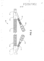
[0020] A presente invenção irá ser descrita em maiores detalhes posteriormente, com referência para concretizações que são ilustradas nos desenhos acompanhantes, nos quais: A Figura 1 mostra uma primeira concretização do cabeamento em concordância com a presente invenção em seção transversal; A Figura 2 mostra a segunda concretização do cabeamento em concordância com a presente invenção; e A Figura 3 mostra um elemento de vedação para cabeamento em concordância com a presente invenção.[0020] The present invention will be described in greater detail later, with reference to embodiments that are illustrated in the accompanying drawings, in which: Figure 1 shows a first embodiment of the cabling in accordance with the present invention in cross section; Figure 2 shows the second embodiment of the cabling in accordance with the present invention; and Figure 3 shows a sealing element for cabling in accordance with the present invention.
[0021] As concretizações da presente invenção e desenvolvimentos adicionais que estão descritos a seguir são somente para serem considerados como exemplos e não são de nenhuma maneira limitantes do escopo de proteção proporcionado pelas reivindicações de patente posteriormente. Nas concretizações aqui descritas, os mesmos numerais de referência nas diferentes Figuras se referem para o mesmo tipo de componente. Cada componente não está, conseqüentemente, descrito em maiores detalhes em todas as concretizações.[0021] The embodiments of the present invention and further developments which are described below are only to be considered as examples and are in no way limiting the scope of protection provided by the patent claims thereafter. In the embodiments described herein, the same reference numerals in the different Figures refer to the same type of component. Each component is therefore not described in greater detail in all embodiments.
[0022] A Figura 1 mostra o cabeamento (1) em concordância com a presente invenção em um corte longitudinal, compreendendo uma mangueira de fluido (2), por exemplo, feita de borracha, com cabo de aquecimento integrado (3) para aquecimento da mangueira (2). A mangueira (2) e o cabo de aquecimento (3) estão englobados em um estojo protetor externo (7). Neste exemplo, o cabo de aquecimento (3) consiste de dois condutos (3a, 3b) que estão embutidos na parede da mangueira (2). Na primeira seção de extremidade (4) do cabeamento, o cabo de aquecimento (3) está separado a partir da mangueira (2) de maneira que este cabo de aquecimento (3) pode ser conduzido para o conector elétrico (6). Na outra seção de extremidade (5) do cabeamento, o cabo de aquecimento (3) está separado a partir da mangueira (2) de maneira que os condutos (3a) e (3b) podem estar conectados juntamente para criar um circuito fechado (não mostrado). É, evidentemente, também possível utilizar um cabo separado que está atado para o exterior da mangueira ou que permanece folgado (solto) no interior do estojo protetor externo (7).[0022] Figure 1 shows the cabling (1) in accordance with the present invention in a longitudinal section, comprising a fluid hose (2), for example, made of rubber, with integrated heating cable (3) for heating the hose (2). The hose (2) and heating cable (3) are enclosed in an external protective case (7). In this example, the heating cable (3) consists of two conduits (3a, 3b) that are embedded in the wall of the hose (2). In the first end section (4) of the cabling, the heating cable (3) is separated from the hose (2) so that this heating cable (3) can be led to the electrical connector (6). In the other end section (5) of the cabling, the heating cable (3) is separated from the hose (2) so that the conduits (3a) and (3b) can be connected together to create a closed circuit (not shown). It is, of course, also possible to use a separate cable which is either tied to the outside of the hose or which remains loose (loose) inside the outer protective case (7).
[0023] A mangueira (2) está proporcionada com conectores de mangueira (8, 9) que estão atados para a mangueira por intermédio de anéis de bloqueio (10). Os conectores de mangueira (8) e (9) são um conector reto e um conector angulado, respectivamente, projetados para estarem conectados para um conector emparelhado. Estes conectores podem, por exemplo, ser conectores montados em mangueira ou conectores montados sobre outras unidades, tais como uma bomba, um vaporizador ou um tanque. Outros tipos de conectores são também possíveis onde requeridos. É também possível conectar a mangueira (2) diretamente para uma tubulação sem ponta (romba) sobre uma unidade, por exemplo, sobre uma bomba, aonde tal seja desejável.[0023] The hose (2) is provided with hose connectors (8, 9) which are tied to the hose by means of locking rings (10). Hose connectors (8) and (9) are a straight connector and an angled connector, respectively, designed to be connected to a paired connector. These connectors can, for example, be hose mounted connectors or connectors mounted on other units such as a pump, a vaporizer or a tank. Other types of connectors are also possible where required. It is also possible to connect the hose (2) directly to a blunt (blunt) pipe over a unit, eg over a pump, where this is desirable.
[0024] O estojo protetor externo (7) do cabeamento está aqui construído de um sistema com mangueiras plásticas corrugadas e conectores associados. O cabeamento que está mostrado na Figura 1 compreende uma mangueira (11) com uma seção transversal interna que excede a seção transversal externa da mangueira (2). Em adição, o cabeamento compreende uma peça intermediária (12), uma peça de ramificação (13) e uma mangueira (14) que toma os condutos (3a, 3b) para o conector elétrico (6). A mangueira (11) e a mangueira (14) possuem aqui diferentes seções transversais, na medida em que o cabo de aquecimento (3) possui uma seção transversal menor do que a da mangueira (2). De maneira a conseguir uma vedação entre os conectores (12, 13) e a mangueira (2), cada seção de extremidade compreende um elemento de vedação (15). O elemento de vedação (15) pode ser um elemento de mancal (de bucha) padronizado na forma de um mancal de borracha ou de um mancal de membrana, por exemplo, do tipo que é utilizado como um mancal de cabo em aparelhos elétricos. Isto significa que todo o cabeamento é construído de componentes padrão, o que significa que o cabeamento acabado (finalizado) é simples e não dispendioso para montagem. É também possível para o elemento de vedação (15) ser manufaturado especialmente quando um elemento de vedação padronizado não é adequado.[0024] The outer protective casing (7) of the cabling is here constructed of a system with corrugated plastic hoses and associated connectors. The cabling that is shown in Figure 1 comprises a hose (11) with an inner cross section that exceeds the outer cross section of the hose (2). In addition, the cabling comprises an intermediate piece (12), a branch piece (13) and a hose (14) which takes conduits (3a, 3b) to the electrical connector (6). The hose (11) and the hose (14) here have different cross sections, as the heating cable (3) has a smaller cross section than the hose (2). In order to achieve a seal between the connectors (12, 13) and the hose (2), each end section comprises a sealing element (15). The sealing element (15) can be a bearing element (bushing) patterned in the form of a rubber bearing or a membrane bearing, for example, of the type that is used as a cable bearing in electrical appliances. This means that all cabling is constructed from standard components, which means that the finished (finished) cabling is simple and inexpensive to assemble. It is also possible for the sealing element (15) to be manufactured especially when a standardized sealing element is not suitable.
[0025] Cada abertura em cada conector está proporcionada com um colar de projeção interno (19) na vizinhança da abertura. Este colar está projetado para prender a mangueira corrugada fixada no conector. Um conector consiste de duas metades que são presas por estalo juntamente durante montagem. Isto significa que os colares em cada metade se combinam para prender a mangueira corrugada fixada na direção longitudinal, na medida em que os colares interagem com uma corrugação na mangueira corrugada. O elemento de vedação (15) está vantajosamente, conseqüentemente, proporcionado com uma ranhura (22) que monta o colar (19) do conector de maneira a, desta maneira, fixar o elemento de vedação (15) no conector. O elemento de vedação (15) pode ser construído de diversas maneiras, mas uma concretização vantajosa é um elemento configurado em disco com uma abertura (23) na metade (no meio) que corresponde para o diâmetro externo do conector de mangueira onde este conector está conectado para a mangueira de fluido (2) e com uma ranhura (22) na superfície de borda que corresponde para o colar (19) no conector. O conector elétrico (6) também compreende um conector (16) com um colar para prender a mangueira corrugada fixada em posição. É, evidentemente, também possível integrar o elemento de vedação em um conector, o que significa projetar o conector de uma maneira tal que uma abertura está projetada para montar e fazer uma vedação diretamente contra um conector de mangueira.[0025] Each opening in each connector is provided with an internal projection collar (19) in the vicinity of the opening. This collar is designed to secure the corrugated hose attached to the connector. A connector consists of two halves that snap together during assembly. This means that the collars on each half combine to secure the fixed corrugated hose in the longitudinal direction, as the collars interact with a corrugation in the corrugated hose. The sealing element (15) is therefore advantageously provided with a groove (22) which mounts the collar (19) of the connector so as to thereby secure the sealing element (15) in the connector. The sealing element (15) can be constructed in several ways, but an advantageous embodiment is a disk-shaped element with an opening (23) in the half (in the middle) which corresponds to the outer diameter of the hose connector where this connector is. connected to the fluid hose (2) and with a groove (22) on the edge surface that corresponds to the collar (19) on the connector. The electrical connector (6) also comprises a connector (16) with a collar for holding the corrugated hose secured in place. It is, of course, also possible to integrate the sealing element into a connector, which means designing the connector in such a way that an opening is designed to mount and seal directly against a hose connector.
[0026] A Figura 2 mostra uma outra concretização de cabeamento (20) em concordância com a presente invenção. Este cabeamento (20) está construído de uma maneira similar para o cabeamento (1) descrito anteriormente. O cabeamento (20) não está mostrado em seção transversal, razão pela qual os componentes englobados não estão mostrados. Está, entretanto, construído a partir do mesmo tipo de componentes padrão como na Figura 1 e possui, por conseqüência, os mesmos numerais de referência.[0026] Figure 2 shows another cabling embodiment (20) in accordance with the present invention. This cabling (20) is constructed in a similar way to the cabling (1) described above. The cabling (20) is not shown in cross section, which is why the enclosed components are not shown. It is, however, constructed from the same kind of standard components as in Figure 1 and therefore has the same reference numerals.
[0027] O cabeamento (20) compreende uma mangueira de fluido (2) com cabo de aquecimento (3) para aquecimento da mangueira (2). A mangueira (2) e o cabo de aquecimento (3) estão englobados em um estojo protetor externo (21). Neste exemplo, o cabo de aquecimento (3) está separado a partir da mangueira (2) em ambas as extremidades da mangueira de maneira que o cabo pode ser tomado para os respectivos conectores elétricos (18). Um conector elétrico é aqui utilizado em cada extremidade do cabeamento, por exemplo, para tomar corrente para um circuito de aquecimento adicional.[0027] The cabling (20) comprises a fluid hose (2) with heating cable (3) for heating the hose (2). The hose (2) and heating cable (3) are enclosed in an external protective case (21). In this example, the heating cable (3) is separated from the hose (2) at both ends of the hose so that the cable can be taken to the respective electrical connectors (18). An electrical connector is used here at each end of the cabling, for example, to draw current for an additional heating circuit.
[0028] A mangueira (2) está aqui proporcionada com conectores de mangueira (9) e (17) que estão atados para a mangueira por intermédio de anéis de bloqueio (10). O conector de mangueira (9) é um conector angulado, e o conector de mangueira (17) é um conector reto para feitura de uma conexão para, por exemplo, uma bomba ou outro cabeamento.[0028] The hose (2) is here provided with hose connectors (9) and (17) which are tied to the hose by means of locking rings (10). The hose connector (9) is an angled connector, and the hose connector (17) is a straight connector for making a connection to, for example, a pump or other cabling.
[0029] O estojo protetor externo (21) do cabeamento (8) está também aqui construído de um sistema com mangueira plástica corrugada e conectores associados. O estojo protetor externo (21) consiste de uma mangueira (11), duas peças de ramificação (13) e duas mangueiras (14) que conduzem o cabo de aquecimento (3) para os conectores elétricos (18). De maneira a conseguir uma vedação entre os dois conectores (13) e a mangueira (2), cada seção de extremidade compreende um elemento de vedação (15), como está descrito anteriormente.[0029] The outer protective case (21) of the cabling (8) is also here constructed of a system with corrugated plastic hose and associated connectors. The outer protective case (21) consists of a hose (11), two branch pieces (13) and two hoses (14) that lead the heating cable (3) to the electrical connectors (18). In order to achieve a seal between the two connectors (13) and the hose (2), each end section comprises a sealing element (15) as described above.
[0030] A Figura 3 mostra um elemento de vedação (15) para feitura de uma vedação entre um conector (12, 13) e a mangueira (2). O elemento de vedação (15) está aqui projetado como um elemento configurado em disco com uma abertura (23) na metade que corresponde para o diâmetro externo de um conector de mangueira onde este conector está conectado para a mangueira de fluido (2) e com uma ranhura (22) na superfície de borda que emparelha para o colar (19) em um conector. O elemento de vedação (15) pode possuir um recesso em uma superfície lateral que está projetada para montar contra a mangueira (2). Desta maneira, o nível de vedação é aumentado. O elemento de vedação (15) torna possível proporcionar cabeamento que combina um sistema com mangueira plástica corrugada e conectores associados, normalmente intencionados para cabeamento elétrico, com uma mangueira de fluido e com um cabo de aquecimento. A vantagem deste sistema é a de que este sistema é construído a partir de componentes padrão não dispendiosos.[0030] Figure 3 shows a sealing element (15) for making a seal between a connector (12, 13) and the hose (2). The sealing element (15) is here designed as a disk-shaped element with an opening (23) in the half that corresponds to the outer diameter of a hose connector where this connector is connected to the fluid hose (2) and with a groove (22) in the edge surface that mates to the collar (19) on a connector. The sealing element (15) may have a recess in a side surface that is designed to mount against the hose (2). In this way, the sealing level is increased. The sealing element (15) makes it possible to provide cabling that combines a system with corrugated plastic hose and associated connectors, normally intended for electrical cabling, with a fluid hose and with a heating cable. The advantage of this system is that this system is built from inexpensive standard components.
[0031] A montagem de um elemento de vedação (15) é realizada da maneira a seguir. A parte do conector de mangueira que faz a conexão com a mangueira de fluido é passada através da abertura (23) e para a mangueira de fluido (2). Quando um mancal de membrana é utilizado como elemento de vedação, o conector de mangueira é inserido através da membrana utilizando uma ferramenta adequada. Depois disto, a mangueira de fluido é fixada em cima do conector de mangueira com o anel de bloqueio (10). A mangueira de fluido vantajosamente faz contato com o elemento de vedação (15). Isto significa que uma vedação de som é conseguida entre a mangueira de fluido (2) e o estojo protetor (7). O elemento de vedação (15) é vantajosamente feito de um material rígido ou ligeiramente flexível, tal como um polímero ou borracha.[0031] The assembly of a sealing element (15) is carried out as follows. The part of the hose connector that makes the connection with the fluid hose is passed through the opening (23) and into the fluid hose (2). When a membrane bearing is used as a sealing element, the hose connector is inserted through the membrane using a suitable tool. After that, the fluid hose is fixed on top of the hose connector with the locking ring (10). The fluid hose advantageously makes contact with the sealing element (15). This means that a sound seal is achieved between the fluid hose (2) and the protective case (7). The sealing element (15) is advantageously made of a rigid or slightly flexible material, such as a polymer or rubber.
[0032] Em determinados casos, a mangueira de fluido não está proporcionada com um conector de mangueira, mas ao invés disso a mangueira de fluido está intencionada para estar conectada diretamente para, por exemplo, uma tubulação sem ponta (romba) sobre um tanque. Nestas circunstâncias, o elemento de vedação (15) está projetado de uma maneira tal que a abertura (23) no elemento de vedação está emparelhada para o diâmetro externo da mangueira de fluido (2). Isto significa que a mangueira se projeta através do elemento de vedação, enquanto que ao mesmo tempo uma vedação de som é obtida entre a mangueira de fluido e um conector. Em determinados casos, é vantajoso utilizar um elemento de vedação que forma uma vedação diretamente entre a mangueira de fluido (2) e o estojo protetor (7), em particular quando somente uma conexão (em linha) reta é requerida.[0032] In certain cases, the fluid hose is not provided with a hose connector, but rather the fluid hose is intended to be connected directly to, for example, a blunt (blunt) pipe over a tank. Under these circumstances, the sealing element (15) is designed in such a way that the opening (23) in the sealing element is matched to the outer diameter of the fluid hose (2). This means that the hose protrudes through the sealing element, while at the same time a sound seal is obtained between the fluid hose and a connector. In certain cases, it is advantageous to use a sealing element which forms a seal directly between the fluid hose (2) and the protective case (7), in particular when only a straight (in-line) connection is required.
[0033] É também possível projetar conectores especiais que são especialmente projetados para formar uma vedação com uma mangueira de fluido, embora isto seja uma solução consideravelmente mais dispendiosa e menos flexível. Ao invés de um número de conectores especiais, é agora suficiente possuir um elemento de vedação especial. Uma outra vantagem de um elemento de vedação separado está associada com a montagem. O elemento de vedação está montado sobre a mangueira de fluido de uma maneira tal que uma mangueira de fluido completa com elemento de vedação e cabos separados pode ser suprida para o ponto de montagem, por exemplo, um manufaturador de ponta de cabo, para montagem do cabeamento. Isto significa que o manufaturador de ponta de cabo não necessita possuir conectores especiais, mas ao invés disso pode gerenciar com a faixa padrão normal. Isto é também vantajoso no acontecimento de um serviço onde a estação de trabalho somente possui componentes padrão disponíveis.[0033] It is also possible to design special connectors that are specially designed to form a seal with a fluid hose, although this is a considerably more expensive and less flexible solution. Instead of a number of special connectors, it is now sufficient to have a special sealing element. Another advantage of a separate sealing element is associated with assembly. The sealing element is mounted over the fluid hose in such a way that a fluid hose complete with sealing element and separate cables can be supplied to the mounting point, eg a cable end manufacturer, for mounting the cabling. This means that the cable end manufacturer does not need to have special connectors, but can instead manage with the normal standard range. This is also advantageous in the event of a service where the workstation only has standard components available.
[0034] A invenção não tem que ser considerada como estando limitada para as concretizações descritas anteriormente, mas um número de variações e de modificações adicionais é conceptível dentro do escopo de proteção das reivindicações de patente posteriormente. Por exemplo, o cabeamento pode não somente ser utilizado para veículos, mas também é adequado para outras aplicações nas quais uma mangueira que é para ser aquecida tem que estar completamente encapsulada. NUMERAIS DE REFERÊNCIA NAS FIGURAS (1) cabeamento (2) mangueira de fluido (3) cabo de aquecimento (3a, 3b) condutos (4) primeira seção de extremidade (5) segunda seção de extremidade (6) conector elétrico fêmea (7) estojo protetor (8) conector reto (9) conector angulado (10) anel de bloqueio (11) mangueira corrugada (12) peça intermediária (13) peça de ramificação (14) mangueira corrugada (15) elemento de vedação (16) conector sobre o conector elétrico (17) conector de mangueira para bomba (18) conector elétrico macho (19) colar (20) cabeamento (21) estojo protetor (22) ranhura (23) abertura[0034] The invention does not have to be considered as being limited to the embodiments described above, but a number of variations and additional modifications are conceivable within the scope of protection of the patent claims thereafter. For example, the cabling can not only be used for vehicles, but it is also suitable for other applications where a hose that is to be heated has to be completely encapsulated. REFERENCE NUMBER IN FIGURES (1) cabling (2) fluid hose (3) heating cable (3a, 3b) conduits (4) first end section (5) second end section (6) female electrical connector (7) protective case (8) straight connector (9) angled connector (10) locking ring (11) corrugated hose (12) intermediate piece (13) branch piece (14) corrugated hose (15) sealing element (16) connector over the electrical connector (17) hose connector for pump (18) male electrical connector (19) collar (20) cabling (21) protective case (22) groove (23) opening
Claims (10)
Applications Claiming Priority (3)
| Application Number | Priority Date | Filing Date | Title |
|---|---|---|---|
| SE0400454A SE528060C2 (en) | 2004-02-25 | 2004-02-25 | Electrically heated cabling |
| SE0400454-5 | 2004-02-25 | ||
| PCT/SE2005/000284 WO2005080850A1 (en) | 2004-02-25 | 2005-02-25 | Electrically heatable cabling |
Publications (2)
| Publication Number | Publication Date |
|---|---|
| BRPI0507952A BRPI0507952A (en) | 2007-07-24 |
| BRPI0507952B1 true BRPI0507952B1 (en) | 2021-10-13 |
Family
ID=31989620
Family Applications (1)
| Application Number | Title | Priority Date | Filing Date |
|---|---|---|---|
| BRPI0507952-7A BRPI0507952B1 (en) | 2004-02-25 | 2005-02-25 | ELECTRICALLY HEATABLE WIRING |
Country Status (9)
| Country | Link |
|---|---|
| US (1) | US20060252292A1 (en) |
| EP (1) | EP1721097B1 (en) |
| JP (1) | JP4708412B2 (en) |
| CN (1) | CN1926372B (en) |
| AT (1) | ATE447132T1 (en) |
| BR (1) | BRPI0507952B1 (en) |
| DE (1) | DE602005017363D1 (en) |
| SE (1) | SE528060C2 (en) |
| WO (1) | WO2005080850A1 (en) |
Families Citing this family (37)
| Publication number | Priority date | Publication date | Assignee | Title |
|---|---|---|---|---|
| CN101300412B (en) * | 2005-09-16 | 2011-06-22 | 戴科流体技术公开有限公司 | Apparatus including heating pipe for purifying vehicle vent gas through selectivity catalytic reduction |
| SE529417C2 (en) * | 2005-12-22 | 2007-08-07 | Volvo Lastvagnar Ab | Wiring harness for a vehicle |
| FR2905161B1 (en) * | 2006-08-25 | 2012-04-20 | Inergy Automotive Systems Res | CONNECTION WITH INTEGRATED HEATING ELEMENT. |
| WO2008131993A1 (en) * | 2007-04-26 | 2008-11-06 | Voss Automotive Gmbh | Line connector for media lines |
| JP4823980B2 (en) * | 2007-07-30 | 2011-11-24 | ニッタ株式会社 | Equipment with heating and heat insulation tubes |
| US7819345B2 (en) * | 2007-09-17 | 2010-10-26 | Shoap Stephen D | Method and system for fluid transmission along significant distances |
| WO2009063980A1 (en) * | 2007-11-15 | 2009-05-22 | Daikin Industries, Ltd. | Fluid transfer tube with heating function and process for producing the fluid transfer tube |
| DE202007018089U1 (en) * | 2007-12-21 | 2009-05-07 | Voss Automotive Gmbh | Heatable media line |
| US9651185B2 (en) | 2008-03-19 | 2017-05-16 | Voss Automotive Gmbh | Line connector for media lines |
| JP5185679B2 (en) * | 2008-04-01 | 2013-04-17 | ニッタ株式会社 | Tube for liquid transfer |
| US7942350B2 (en) * | 2008-09-16 | 2011-05-17 | Shoap Stephen D | Method and system for fluid transmission along significant distances |
| DE102010010765A1 (en) | 2010-03-09 | 2011-09-15 | Eugen Forschner Gmbh | Apparatus and method for connecting a fluid carrying conduit to an adjacent component |
| DE102010032189A1 (en) | 2010-07-23 | 2012-01-26 | Voss Automotive Gmbh | Heatable media line and method for its production |
| DE102010032188A1 (en) | 2010-07-23 | 2012-01-26 | Voss Automotive Gmbh | Heatable media line |
| DE102010035028B4 (en) | 2010-08-20 | 2013-07-18 | Voss Automotive Gmbh | Heated cable connectors with insulation and / or protective cover and heatable media cable with at least one cable connector with insulation and / or protective cover |
| ITTO20100773A1 (en) * | 2010-09-22 | 2012-03-23 | Dytech Dynamic Fluid Tech Spa | PIPE FOR A SCR CIRCUIT OF A VEHICLE |
| DE102012002411A1 (en) | 2011-02-10 | 2012-10-18 | Voss Automotive Gmbh | Heatable medium spacer for use in vehicle e.g. lorry, has heating element with strands constantly extended along medium spacer part and spacer connector, and fastening unit for attaching strands to media spacer part or insulation device |
| DE102011018482A1 (en) * | 2011-04-21 | 2012-10-25 | Rehau Ag + Co. | Media line, in particular for the transport of urea-water solutions |
| DE102011102244B4 (en) | 2011-05-20 | 2014-12-31 | Norma Germany Gmbh | Connector for a heated fluid line and heated fluid line |
| DE102011102148A1 (en) | 2011-05-20 | 2012-11-22 | Norma Germany Gmbh | fluid line |
| DE102011102151B4 (en) | 2011-05-20 | 2022-05-19 | Norma Germany Gmbh | fluid line |
| US9073187B2 (en) * | 2011-11-04 | 2015-07-07 | Hurricane Safety Systems, Llc | Cable tensioning device |
| US9108309B2 (en) * | 2011-11-04 | 2015-08-18 | Hurricane Safety Systems, Llc | Cable tensioning device for hunting tree stands or climbing ladders |
| GB2526831B (en) * | 2014-06-03 | 2016-10-19 | Acergy France SAS | Branch structures of electrically-heated pipe-in-pipe flowlines |
| CN105179054A (en) * | 2015-10-17 | 2015-12-23 | 浙江三叶机械有限公司 | Constant temperature electrical heating urea liquid inlet pipe |
| EP3026318B1 (en) * | 2015-12-23 | 2018-02-14 | TI Automotive (Fuldabrück) GmbH | Connector with mounting aid and method for producing a connector |
| EP3276243B2 (en) * | 2016-07-28 | 2021-11-10 | TI Automotive (Fuldabrück) GmbH | Fluid line for motor vehicle |
| US11014105B2 (en) * | 2016-10-15 | 2021-05-25 | Akurate Dynamics, Llc | Multi-segment heated hose having segment-specific heating means |
| DE102016122319A1 (en) * | 2016-11-21 | 2018-05-24 | Norma Germany Gmbh | Connectors |
| US20180195657A1 (en) * | 2017-01-06 | 2018-07-12 | Campbell Hausfeld, Llc | Illuminated hose |
| WO2018138581A1 (en) | 2017-01-30 | 2018-08-02 | Globalmed, Inc. | Heated respiratory hose assembly |
| EP3382255B1 (en) * | 2017-03-29 | 2019-07-03 | TI Automotive (Fuldabrück) GmbH | Pipeline comprising a connector and method for operating this pipeline |
| US20190189472A1 (en) * | 2017-12-18 | 2019-06-20 | Trebor International | Pfa tube heater with flexible heating elements |
| DE102018103571A1 (en) * | 2018-02-16 | 2019-08-22 | Voss Automotive Gmbh | Connecting arrangement for connecting heated fluid lines |
| EP3787839A4 (en) * | 2018-05-01 | 2022-01-19 | Revolok Technologies, LLC | Tensioning device |
| US10190716B1 (en) * | 2018-09-11 | 2019-01-29 | Akurate Dynamics, Llc | Heated hose with improved power feedthrough |
| AU2020380339B2 (en) | 2019-11-05 | 2022-07-07 | Revolok Technologies, Llc | Tensioning device and driven member thereof |
Family Cites Families (34)
| Publication number | Priority date | Publication date | Assignee | Title |
|---|---|---|---|---|
| US1806942A (en) * | 1931-05-26 | hendricks | ||
| US1818176A (en) * | 1929-02-19 | 1931-08-11 | Electric Heating Devices Inc | Electrical heater |
| US1809714A (en) * | 1929-04-01 | 1931-06-09 | Mathews Carl Raymond | Heated water hose for filling stations |
| US2484063A (en) * | 1944-08-19 | 1949-10-11 | Thermactor Corp | Electric heater for subsurface materials |
| US2527011A (en) * | 1948-10-25 | 1950-10-24 | William F Keil | Circulatory heating system for vehicle motors |
| US2778609A (en) * | 1954-12-10 | 1957-01-22 | Devilbiss Co | Composite hose with temperature control |
| US2824209A (en) * | 1956-07-20 | 1958-02-18 | Welcraft Products Co Inc | Strip heater |
| US3120600A (en) * | 1962-07-02 | 1964-02-04 | Cecil W True | Freezeless water supply |
| US3378673A (en) * | 1965-10-18 | 1968-04-16 | Thomas O. Hopper | Electrically heated hose assembly |
| US3784785A (en) | 1971-09-20 | 1974-01-08 | W Noland | Electrically heated fluid conduit coupler |
| NL7414546A (en) * | 1973-11-15 | 1975-05-20 | Rhone Poulenc Sa | SMOOTH HEATING TUBE AND PROCESS FOR MANUFACTURING IT. |
| JPS5494619U (en) * | 1977-12-16 | 1979-07-04 | ||
| US4214147A (en) | 1978-06-19 | 1980-07-22 | Kraver Richard A | Electric heating system for controlling temperature of pipes to prevent freezing and condensation |
| US4553023A (en) * | 1981-11-27 | 1985-11-12 | Nordson Corporation | Thermally insulated electrically heated hose for transmitting hot liquids |
| US4455474A (en) * | 1981-11-27 | 1984-06-19 | Nordson Corporation | Thermally insulated electrically heated hose for transmitting hot liquids |
| US4484061A (en) * | 1982-05-13 | 1984-11-20 | Sys-Tec, Inc. | Temperature control system for liquid chromatographic columns employing a thin film heater/sensor |
| US4650964A (en) * | 1984-02-21 | 1987-03-17 | Hewlett-Packard Company | Electrically heated transfer line for capillary tubing |
| US4728776A (en) * | 1984-02-21 | 1988-03-01 | Hewlett-Packard Company | Heated transfer line for capillary tubing |
| US5277227A (en) * | 1984-08-15 | 1994-01-11 | Dayco Products, Inc. | Plastic abrasion-resistant protective sleeve for hose |
| JPS61184184U (en) * | 1985-05-08 | 1986-11-17 | ||
| US4644134A (en) * | 1985-09-25 | 1987-02-17 | Nordson Corporation | Electrically heated hose having corrugated plastic cover |
| DE3900821C1 (en) | 1989-01-13 | 1990-04-19 | Technoform Caprano + Brunnhofer Kg, 3501 Fuldabrueck, De | Fluid-carrying hose line for a motor vehicle |
| FR2670862B1 (en) * | 1990-12-21 | 1993-06-11 | Coflexip | FLEXIBLE PIPE WITH IMPROVED THERMAL PROTECTION. |
| JP2576023Y2 (en) * | 1991-12-05 | 1998-07-09 | 株式会社カンセイ | Grommet |
| US5600752A (en) * | 1994-03-11 | 1997-02-04 | Industrial Design Laboratories, Inc. | Flexible gas hose assembly with concentric helical tube members having reinforcement spring coils |
| US5791377A (en) * | 1996-07-08 | 1998-08-11 | Yazaki Corporation | Electrically heated conduit |
| US5933574A (en) * | 1998-02-09 | 1999-08-03 | Avansino; Gary L. | Heated fluid conduit |
| DE19844485A1 (en) | 1998-09-28 | 2000-03-30 | Continental Teves Ag & Co Ohg | Heatable pipe line for a hydraulic braking unit, in particular, for motor vehicles comprises a first cover element accommodating heater leads running in the direction of the pipe line axis |
| CA2408428C (en) * | 2001-10-17 | 2010-09-21 | Lorne R. Heise | Fluid conduit |
| DE50102005D1 (en) * | 2001-11-28 | 2004-05-19 | Festo Ag & Co | Connection piece, fluid line and fluid technology device |
| DE10201920B4 (en) | 2002-01-19 | 2018-04-12 | Contitech Schlauch Gmbh | Method for connecting a heating conductor of a flexible multilayered hose with an electrical connection device |
| US6727481B1 (en) * | 2003-06-06 | 2004-04-27 | Robert C. Wilds | Heated conduit |
| US7084377B2 (en) * | 2003-10-31 | 2006-08-01 | Nordson Corporation | Heated device and method of redundant temperature sensing |
| US7266293B1 (en) * | 2004-05-03 | 2007-09-04 | Dundas Robert D | Hose for hot liquids having heating element |
-
2004
- 2004-02-25 SE SE0400454A patent/SE528060C2/en not_active IP Right Cessation
-
2005
- 2005-02-25 EP EP05711144A patent/EP1721097B1/en not_active Revoked
- 2005-02-25 WO PCT/SE2005/000284 patent/WO2005080850A1/en active Application Filing
- 2005-02-25 BR BRPI0507952-7A patent/BRPI0507952B1/en active IP Right Grant
- 2005-02-25 JP JP2007500722A patent/JP4708412B2/en not_active Expired - Fee Related
- 2005-02-25 AT AT05711144T patent/ATE447132T1/en not_active IP Right Cessation
- 2005-02-25 DE DE602005017363T patent/DE602005017363D1/en active Active
- 2005-02-25 CN CN200580006170XA patent/CN1926372B/en active Active
-
2006
- 2006-07-14 US US11/457,657 patent/US20060252292A1/en not_active Abandoned
Also Published As
| Publication number | Publication date |
|---|---|
| US20060252292A1 (en) | 2006-11-09 |
| CN1926372A (en) | 2007-03-07 |
| CN1926372B (en) | 2013-04-17 |
| ATE447132T1 (en) | 2009-11-15 |
| JP2007524053A (en) | 2007-08-23 |
| SE0400454L (en) | 2005-08-26 |
| SE528060C2 (en) | 2006-08-22 |
| SE0400454D0 (en) | 2004-02-25 |
| EP1721097A1 (en) | 2006-11-15 |
| DE602005017363D1 (en) | 2009-12-10 |
| JP4708412B2 (en) | 2011-06-22 |
| EP1721097B1 (en) | 2009-10-28 |
| BRPI0507952A (en) | 2007-07-24 |
| WO2005080850A1 (en) | 2005-09-01 |
Similar Documents
| Publication | Publication Date | Title |
|---|---|---|
| BRPI0507952B1 (en) | ELECTRICALLY HEATABLE WIRING | |
| BRPI0620457A2 (en) | heated coupling | |
| US20070176418A1 (en) | Electrically heatable coupling and an encased fluid hose with an electrically heatable coupling | |
| US5791377A (en) | Electrically heated conduit | |
| US7857645B2 (en) | Connector arrangement for a medium-conducting, electrically-heatable hose | |
| US9343838B2 (en) | Method for producing a sealed connector and the sealed connector obtained | |
| US9644776B2 (en) | Prefabricated electrically heatable media line and method for producing a media line of this kind | |
| US20110006513A1 (en) | Line Connector for Media Lines and Ready-Made Media Line With at Least One Such Line Connector | |
| US9147988B2 (en) | Device for connecting a line element to a component | |
| BR112012031838B1 (en) | head unit and combination | |
| CN102597592B (en) | Can electrically heated media lines and guide coupling | |
| BR102013022833A2 (en) | FITTING CONNECTOR | |
| US9366454B2 (en) | Heatable connection apparatus including media-conducting, electrically heatable hoses | |
| BR112012010457B1 (en) | system to connect hose lines | |
| US7810846B2 (en) | Electrostatic dissipation solution for angled fuel port of a fuel supply unit | |
| BR102019011608A2 (en) | connecting head with a return cavity | |
| US20080042435A1 (en) | Interface hose seal for low permeation fuel supply unit flange | |
| US8070187B2 (en) | Interface hose seal for low permeation flange of a fuel supply unit | |
| CN209982599U (en) | Waterproof structure of lower shell assembly of vehicle-mounted camera module | |
| BR102014004391A2 (en) | arrangement consisting of a hose-type hydraulic line |
Legal Events
| Date | Code | Title | Description |
|---|---|---|---|
| B06F | Objections, documents and/or translations needed after an examination request according [chapter 6.6 patent gazette] | ||
| B07A | Application suspended after technical examination (opinion) [chapter 7.1 patent gazette] | ||
| B07A | Application suspended after technical examination (opinion) [chapter 7.1 patent gazette] | ||
| B09B | Patent application refused [chapter 9.2 patent gazette] | ||
| B12B | Appeal against refusal [chapter 12.2 patent gazette] | ||
| B16A | Patent or certificate of addition of invention granted [chapter 16.1 patent gazette] |
Free format text: PRAZO DE VALIDADE: 20 (VINTE) ANOS CONTADOS A PARTIR DE 25/02/2005, OBSERVADAS AS CONDICOES LEGAIS. PATENTE CONCEDIDA CONFORME ADI 5.529/DF, QUE DETERMINA A ALTERACAO DO PRAZO DE CONCESSAO. |