BRPI0414986B1 - system and method for making fiber optic connections in an underground well - Google Patents
system and method for making fiber optic connections in an underground well Download PDFInfo
- Publication number
- BRPI0414986B1 BRPI0414986B1 BRPI0414986-6A BRPI0414986A BRPI0414986B1 BR PI0414986 B1 BRPI0414986 B1 BR PI0414986B1 BR PI0414986 A BRPI0414986 A BR PI0414986A BR PI0414986 B1 BRPI0414986 B1 BR PI0414986B1
- Authority
- BR
- Brazil
- Prior art keywords
- fiber optic
- assembly
- well
- connector
- fact
- Prior art date
Links
- 239000000835 fiber Substances 0.000 title claims abstract description 186
- 238000000034 method Methods 0.000 title claims abstract description 29
- 239000013307 optical fiber Substances 0.000 claims abstract description 28
- 230000000712 assembly Effects 0.000 claims description 10
- 238000000429 assembly Methods 0.000 claims description 10
- 238000004519 manufacturing process Methods 0.000 claims description 5
- 230000004308 accommodation Effects 0.000 claims description 2
- 230000004044 response Effects 0.000 claims description 2
- 230000008878 coupling Effects 0.000 claims 1
- 238000010168 coupling process Methods 0.000 claims 1
- 238000005859 coupling reaction Methods 0.000 claims 1
- 230000015572 biosynthetic process Effects 0.000 abstract description 20
- 238000012544 monitoring process Methods 0.000 abstract description 6
- 230000003287 optical effect Effects 0.000 abstract description 2
- 239000000523 sample Substances 0.000 description 52
- 238000005755 formation reaction Methods 0.000 description 18
- 239000012530 fluid Substances 0.000 description 6
- 230000007246 mechanism Effects 0.000 description 6
- 230000009286 beneficial effect Effects 0.000 description 4
- 230000008901 benefit Effects 0.000 description 4
- 238000004891 communication Methods 0.000 description 4
- 238000003825 pressing Methods 0.000 description 4
- 238000001514 detection method Methods 0.000 description 3
- XLYOFNOQVPJJNP-UHFFFAOYSA-N water Substances O XLYOFNOQVPJJNP-UHFFFAOYSA-N 0.000 description 3
- 229910000831 Steel Inorganic materials 0.000 description 2
- 238000007792 addition Methods 0.000 description 2
- 238000009826 distribution Methods 0.000 description 2
- 239000010959 steel Substances 0.000 description 2
- 230000005540 biological transmission Effects 0.000 description 1
- 239000004020 conductor Substances 0.000 description 1
- 238000012217 deletion Methods 0.000 description 1
- 230000037430 deletion Effects 0.000 description 1
- 238000005516 engineering process Methods 0.000 description 1
- 230000004941 influx Effects 0.000 description 1
- 230000009545 invasion Effects 0.000 description 1
- 238000012986 modification Methods 0.000 description 1
- 230000004048 modification Effects 0.000 description 1
- 230000001681 protective effect Effects 0.000 description 1
- 238000005086 pumping Methods 0.000 description 1
- 238000011084 recovery Methods 0.000 description 1
- 238000007789 sealing Methods 0.000 description 1
- 230000000638 stimulation Effects 0.000 description 1
- 238000006467 substitution reaction Methods 0.000 description 1
- 238000011282 treatment Methods 0.000 description 1
Images


Classifications
-
- E—FIXED CONSTRUCTIONS
- E21—EARTH DRILLING; MINING
- E21B—EARTH DRILLING, e.g. DEEP DRILLING; OBTAINING OIL, GAS, WATER, SOLUBLE OR MELTABLE MATERIALS OR A SLURRY OF MINERALS FROM WELLS
- E21B17/00—Drilling rods or pipes; Flexible drill strings; Kellies; Drill collars; Sucker rods; Cables; Casings; Tubings
- E21B17/02—Couplings; joints
- E21B17/028—Electrical or electro-magnetic connections
-
- G—PHYSICS
- G02—OPTICS
- G02B—OPTICAL ELEMENTS, SYSTEMS OR APPARATUS
- G02B6/00—Light guides; Structural details of arrangements comprising light guides and other optical elements, e.g. couplings
- G02B6/24—Coupling light guides
- G02B6/36—Mechanical coupling means
- G02B6/38—Mechanical coupling means having fibre to fibre mating means
- G02B6/3807—Dismountable connectors, i.e. comprising plugs
- G02B6/389—Dismountable connectors, i.e. comprising plugs characterised by the method of fastening connecting plugs and sockets, e.g. screw- or nut-lock, snap-in, bayonet type
Abstract
"SISTEMA E MÉTODO PARA FAZER CONEXÕES DE FIBRA ÓPTICA EM UM POÇO SUBTERRÂNEO, APARELHO E SISTEMA PARA FAZER UMA CONEXÃO ENTRE LINHAS EM UM POÇO SUBTERRÂNEO, E, MÉTODO PARA MONITORAR UM POÇO SUBTERRÂNEO". É descrita uma conexão úmida de fibra óptica de furo abaixo e completação com recheio de cascalho. Em uma modalidade descrita, o sistema para fazer conexões de fibra óptica em um poço subterrâneo inclui um primeiro conector de fibra óptica posicionado no poço e um segundo conector de fibra óptica conectado operacionalmente no primeiro conector de fibra óptica depois que o primeiro conector de fibra óptica for posicionado no poço. Um método de monitoramento de um poço subterrâneo inclui as etapas de: posicionar uma fibra óptica em linha no poço, a linha de fibra óptica se estendendo em uma formação interceptada pelo poço; posicionar uma outra linha de fibra óptica no poço, a linha de fibra óptica se estendendo até um local remoto; conectado operacionalmente as linhas de fibra óptica enquanto as linhas de fibra óptica estão no poço; e monitorar um parâmetro do poço usando um sensor acoplado operacionalmente na linha de fibra óptica que se estende na formação."SYSTEM AND METHOD FOR MAKING FIBER OPTICAL CONNECTIONS IN AN UNDERGROUND WELL, APPARATUS AND SYSTEM FOR MAKING A CONNECTION BETWEEN LINES IN AN UNDERGROUND WELL, AND, METHOD FOR MONITORING AN UNDERGROUND WELL". A wet fiber optic connection is described below and completed with gravel filling. In a described embodiment, the system for making fiber optic connections in an underground well includes a first fiber optic connector positioned in the well and a second fiber optic connector operationally connected to the first fiber optic connector after the first fiber optic connector. is positioned in the well. A method of monitoring an underground well includes the steps of: placing an optical fiber in line in the well, the optical fiber line extending in a formation intercepted by the well; position another fiber optic line in the well, the fiber optic line extending to a remote location; operationally connected the optical fiber lines while the optical fiber lines are in the well; and monitor a well parameter using a sensor operationally coupled to the fiber optic line that extends into the formation.
Description
A presente invenção diz respeito no geral a equipamento utilizado e operações realizadas em montagem com poços subterrâneos e, em uma modalidade aqui descrita, mais particularmente fornece uma conexão úmida de fibra óptica de furo abaixo e completação com recheio de cascalho.The present invention relates in general to equipment used and operations carried out in assembly with underground wells and, in an embodiment described here, more particularly it provides a wet fiber optic connection with hole below and completion with gravel filling.
Seria bastante desejável poder usar uma linha de fibra óptica para monitorar a produção de um poço, por exemplo, monitorar invasão de água, identificar fontes de produção, avaliar tratamentos de estimulação e práticas de completação, etc. É de conhecimento usar linhas de fibra óptica para transmitir indicações de sensores de furo abaixo, comunicar com o ambiente de furo abaixo e usar uma linha de fibra óptica como um sensor.It would be very desirable to be able to use a fiber optic line to monitor the production of a well, for example, to monitor water invasion, to identify production sources, to evaluate stimulation treatments and completion practices, etc. It is known to use fiber optic lines to transmit indications from hole sensors below, communicate with the hole environment below and use a fiber optic line as a sensor.
O documento US 4690212 refere-se a um tubo de perfuração e um sistema de conexão de tubo de perfuração melhorados para uso com um motor elétrico de furo de poço. Mais especificamente, a invenção refere-se a um tubo de perfuração feito a partir de um feixe de fios ou hastes que também serve como um condutor elétrico para o motor de furo de poço. O documento US 2003181085 refere-se, de modo geral, a operações executadas e equipamento utilizado em conjunto com um poço subterrâneo e, mais particularmente, fornece métodos e aparelhos para interligar os conjuntos de ferramentas de poço em tubos contínuos.US 4690212 relates to an improved drill pipe and drill pipe connection system for use with an electric borehole motor. More specifically, the invention relates to a drill pipe made from a bundle of wires or rods that also serves as an electrical conductor for the borehole motor. US 2003181085 relates generally to operations performed and equipment used in conjunction with an underground well and, more particularly, provides methods and apparatus for interconnecting well tool sets in continuous tubes.
No entanto, nenhum documento do estado da técnica revela uma conexão de partes separadas da linha de fibra óptica a serem instaladas e conectadas operacionalmente entre si em um poço e com completação com recheio de cascalho.However, no state-of-the-art document reveals a connection of separate parts of the fiber optic line to be installed and operationally connected to each other in a well and complete with gravel filling.
Entretanto, linhas de fibra óptica podem se danificar em operações tais como recheio de cascalho, expansão de unidades tubulares no fundo do poço, etc. Por este motivo, seria benéfico poder substituir partes de uma linha de fibra óptica de furo abaixo, ou instalar uma linha de fibra óptica substituta. Esta operação de substituição seria mais econômica se uma coluna de completação não tivesse que ser recuperada de um poço para substituir/instalar a linha de fibra óptica.However, fiber optic lines can be damaged in operations such as gravel filling, expansion of tubular units at the bottom of the shaft, etc. For this reason, it would be beneficial to be able to replace parts of a fiber optic line down the hole, or to install a substitute fiber optic line. This replacement operation would be more economical if a completion column did not have to be recovered from a well to replace / install the fiber optic line.
Além disso, algumas vezes é desejável completar um poço em seções ou intervalos, por exemplo, onde um poço horizontal recheado com cascalho em seções, ou onde zonas interceptadas por um poço vertical são recheadas com cascalho separadamente. Nesses casos, seria benéfico poder conectar seções separadas de linha de fibra óptica umas nas outras no fundo do poço, de maneira tal que a linha de fibra óptica possa ser instalada em sistemas juntamente com seções correspondentes da completação.In addition, it is sometimes desirable to complete a well in sections or intervals, for example, where a horizontal well filled with gravel in sections, or where areas intercepted by a vertical well are filled with gravel separately. In such cases, it would be beneficial to be able to connect separate sections of fiber optic line to each other at the bottom of the well, in such a way that the fiber optic line can be installed in systems together with corresponding sections of the completion.
Na realização dos princípios da presente invenção, de acordo com suas modalidades, é provido um sistema que permite que conectores de fibra óptica sejam conectados no fundo do poço. Com uso deste sistema, partes separadas da linha de fibra óptica podem ser instaladas em um poço, e em seguida conectadas operacionalmente entre si. Além disso, uma linha de fibra óptica previamente instalada em um poço pode ser substituída, sem ter que puxar a coluna da tubulação de produção para fora do poço.In carrying out the principles of the present invention, according to its modalities, a system is provided that allows fiber optic connectors to be connected at the bottom of the well. Using this system, separate parts of the fiber optic line can be installed in a well, and then operationally connected to each other. In addition, a fiber optic line previously installed in a well can be replaced, without having to pull the production pipe column out of the well.
Em um aspecto da invenção, é provido um sistema para fazer conexões de fibra óptica em um poço subterrâneo. O sistema inclui um conector de fibra óptica posicionado no poço. Um outro conector de fibra óptica é conectado operacionalmente ao primeiro conector de fibra óptica depois que o primeiro conector de fibra óptica estiver posicionado no poço.In one aspect of the invention, a system is provided for making fiber optic connections in an underground well. The system includes a fiber optic connector positioned in the well. Another fiber optic connector is operationally connected to the first fiber optic connector after the first fiber optic connector is positioned in the well.
Em um outro aspecto da invenção, um sistema para fazer conexões de fibra óptica em um poço subterrâneo inclui uma montagem posicionada no poço, a montagem incluindo um conector de fibra óptica. Uma outra montagem é posicionada no poço, a qual inclui um outro conector de fibra óptica. Um dispositivo de orientação orienta as montagens uma em relação à outra, alinhando assim os conectores de fibra óptica.In another aspect of the invention, a system for making fiber optic connections in an underground well includes an assembly positioned in the well, the assembly including a fiber optic connector. Another assembly is positioned in the well, which includes another fiber optic connector. An orientation device guides the assemblies in relation to each other, thus aligning the fiber optic connectors.
Também em um outro aspecto da invenção, é provido um método para fazer conexões de fibra óptica em um poço subterrâneo. O método inclui as etapas de: posicionar uma outra montagem no poço que inclui um outro conector de fibra óptica; orientar as montagens no poço, alinhando assim os conectores de fibra óptica; e em seguida conectar operacionalmente os conectores de fibra óptica no poço.Also in another aspect of the invention, a method is provided for making fiber optic connections in an underground well. The method includes the steps of: positioning another assembly in the well that includes another fiber optic connector; guide the assemblies in the well, thus aligning the fiber optic connectors; and then operationally connect the fiber optic connectors to the well.
Em um aspecto adicional da invenção, é provido um aparelho para fazer uma conexão de fibra óptica em um poço subterrâneo. O aparelho inclui um alojamento externo que tem uma parede lateral, e uma passagem que se estende através do alojamento. Um conector de fibra óptica fica posicionado na parede lateral do alojamento. Um outro conector de fibra óptica é recebido dentro da passagem. Os conectores de fibra óptica são conectáveis operacionalmente depois que o aparelho é posicionado no poço.In a further aspect of the invention, an apparatus is provided for making a fiber optic connection in an underground well. The apparatus includes an external housing that has a side wall, and a passage that extends through the housing. A fiber optic connector is located on the side wall of the housing. Another fiber optic connector is received inside the passageway. The fiber optic connectors are operably connectable after the device is positioned in the well.
Em mais um aspecto adicional da invenção, um sistema para fazer conexões de fibra óptica em um poço subterrâneo inclui uma montagem do obturador que tem um dispositivo de orientação e um conector de fibra óptica. Uma coluna tubular do sistema inclui um outro dispositivo de orientação e um outro conector de fibra óptica. Os dispositivos de orientação alinham os conectores de fibra óptica para conexão operacional entre eles quando a coluna tubular for encaixada no obturador no poço.In a further aspect of the invention, a system for making fiber optic connections in an underground well includes a plug assembly that has a guiding device and a fiber optic connector. A tubular column of the system includes another guiding device and another fiber optic connector. The guidance devices align the fiber optic connectors for operational connection between them when the tubular column is fitted to the plug in the well.
Também em um outro aspecto da invenção, é provido um sistema para fazer conexões de fibra óptica em um poço subterrâneo. O sistema inclui uma coluna tubular que tem uma passagem formada através da coluna tubular, e um conector de fibra óptica e uma montagem recebida na passagem, a montagem tendo um outro conector de fibra óptica.Also in another aspect of the invention, a system is provided for making fiber optic connections in an underground well. The system includes a tubular column that has a passage formed through the tubular column, and a fiber optic connector and an assembly received in the passage, the assembly having another fiber optic connector.
Um aspecto adicional da invenção inclui um método de monitoramento de um poço subterrâneo. O método inclui as etapas de: posicionar uma linha de fibra óptica no poço, a linha de fibra óptica se estendendo em uma formação interceptada pelo poço; posicionar uma outra linha de fibra óptica no poço, a linha de fibra óptica se estendendo até um local remoto; conectar operacionalmente as linhas de fibra óptica enquanto as linhas de fibra óptica estão no poço; e monitorar um parâmetro do poço usando um sensor acoplado operacionalmente à linha de fibra óptica que se estende na formação.An additional aspect of the invention includes a method of monitoring an underground well. The method includes the steps of: positioning an optical fiber line in the well, the optical fiber line extending in a formation intercepted by the well; position another fiber optic line in the well, the fiber optic line extending to a remote location; operationally connect the optical fiber lines while the optical fiber lines are in the well; and monitor a well parameter using a sensor operationally coupled to the fiber optic line that extends in the formation.
Esses e outros recursos, vantagens, benefícios e objetivos da presente invenção ficarão aparentes aos versados na técnica mediante consideração criteriosa da descrição detalhada de modalidades representativas da invenção a seguir e dos desenhos anexos.These and other features, advantages, benefits and objectives of the present invention will become apparent to those skilled in the art upon careful consideration of the detailed description of representative modalities of the invention below and the accompanying drawings.
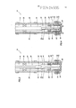
As figuras 1-4 são sucessivas vistas seccionais transversais parciais esquemáticas de um sistema e método que incorpora os princípios da presente invenção;Figures 1-4 are successive schematic partial cross-sectional views of a system and method that incorporates the principles of the present invention;
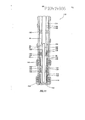
As figuras 5A e B são vistas seccionais transversais ampliadas de um aparelho de conexão úmida de fibra óptica que incorpora os princípios da presente invenção;Figures 5A and B are enlarged cross-sectional views of a wet fiber optic connection apparatus that incorporates the principles of the present invention;
As figuras 6A e B são vistas seccionais transversais do aparelho de conexão úmida das figuras 5A e B com a sonda de fibra óptica encaixada nele;Figures 6A and B are cross-sectional views of the wet connection apparatus of figures 5A and B with the fiber optic probe attached to it;
A figura 7 é uma vista parcialmente seccional transversal esquemática de um outro sistema e método que incorporam os princípios da invenção; eFigure 7 is a partially schematic cross-sectional view of another system and method that incorporates the principles of the invention; and
As figuras 8-11 são sucessivas vistas seccionais transversais parciais esquemáticas de mais um outro sistema e método que incorporam os princípios da invenção.Figures 8-11 are successive schematic partial cross-sectional views of yet another system and method that incorporate the principles of the invention.
Nas figuras 1-4 estão ilustrados representativamente um sistema 10 e método que incorporam os princípios da presente invenção. Na descrição seguinte do sistema 10 e de outros aparelhos e métodos aqui descritos, os termos direcionais, tais como “acima”, “abaixo”, “superior”, “inferior”, etc., são usados somente por conveniência na referência aos desenhos anexos. Adicionalmente, deve-se entender que as várias modalidades da presente invenção aqui descritas podem ser utilizadas em várias orientações, tais como inclinada, invertida, horizontal, vertical, etc., e em várias configurações, sem fugir dos princípios da presente invenção.Figures 1-4 illustrate a system 10 and method that incorporate the principles of the present invention. In the following description of system 10 and other devices and methods described here, directional terms, such as "above", "below", "upper", "lower", etc., are used only for convenience in reference to the attached drawings . Additionally, it should be understood that the various modalities of the present invention described herein can be used in various orientations, such as inclined, inverted, horizontal, vertical, etc., and in various configurations, without departing from the principles of the present invention.
O sistema 10 e método são usados para demonstrar como os princípios da invenção podem proporcionar vários benefícios em uma aplicação de monitoramento de poço. Entretanto, deve-se entender claramente que os princípios da invenção não estão limitados ao uso com o sistema 10 e o método representado nas figuras 1-4, mas são, em vez disso, adaptáveis a uma ampla variedade de aplicações. Portanto, os detalhes do sistema 10 e método das figuras 1-4, ou de qualquer dos outros sistemas e métodos aqui descritos, não devem ser considerados como limitação dos princípios da invenção.System 10 and method are used to demonstrate how the principles of the invention can provide various benefits in a well monitoring application. However, it must be clearly understood that the principles of the invention are not limited to use with system 10 and the method represented in figures 1-4, but are, instead, adaptable to a wide variety of applications. Therefore, the details of system 10 and method of figures 1-4, or any of the other systems and methods described herein, should not be considered as limiting the principles of the invention.
Conforme representado na figura 1, uma montagem de recheio de cascalho 12 foi posicionada em um furo do poço 14 que intercepta uma formação ou zona 16. Toda ou parte da montagem de recheio de cascalho 12 pode ficar posicionada em uma parte revestida ou não revestida do furo do poço 14.As shown in figure 1, a
A montagem 12 inclui um filtro do poço 18 e um obturador com recheio de cascalho 20. O obturador 20 é montado no furo do poço 14, e a coroa anular entre o filtro do poço 18 e o furo do poço é recheado com cascalho 22, usando técnicas bem conhecidas pelos especialistas. Um dispositivo de controle de perda de fluido 24 pode ser usado para impedir que fluido no furo do poço 14 escoe para a formação 16 depois da operação de recheio de cascalho.
Conforme representado na figura 2, uma coluna tubular 26, tal como uma coluna tubular de produção, é transferida para o furo do poço 14 e encaixada na montagem de recheio de cascalho 12. Vedações 18 que vão na coluna tubular 26 encaixam de forma vedada um furo de vedação 30 da montagem 12, tal como um furo polido do obturador 20.As shown in figure 2, a
A coluna tubular 26 inclui uma montagem do alojamento no geral tubular ou receptáculo 32. Uma linha de fibra óptica 34 se estende de um local remoto (não mostrado), tais como a superfície terrestre ou um outro local no poço, até um conector de fibra óptica 36 localizado na montagem do alojamento 32.The
Na forma aqui usada, o termo “conector de fibra óptica” é usado para indicar um conector que é acoplado operacionalmente a uma linha de fibra óptica, de maneira tal que, quando um conector de fibra óptica for conectado em um outro conector de fibra óptica, luz possa ser transmitida de uma linha de fibra óptica para uma outra linha de fibra óptica. Assim, cada conector de fibra óptica tem uma linha de fibra óptica acoplada operacionalmente nele, e as linhas de fibra óptica são conectadas para transmissão de luz entre eles quando os conectores forem conectados entre si.In the form used here, the term "fiber optic connector" is used to indicate a connector that is operationally coupled to a fiber optic line, such that when a fiber optic connector is connected to another fiber optic connector , light can be transmitted from one fiber optic line to another fiber optic line. Thus, each fiber optic connector has a fiber optic line operationally attached to it, and the fiber optic lines are connected for light transmission between them when the connectors are connected to each other.
Embora na descrição seguinte do sistema 10 e do método associado somente uma linha de fibra óptica 34 esteja especificamente descrita, deve-se entender claramente que qualquer quantidade de linhas de fibra óptica pode ser usada no sistema e método, e qualquer quantidade de conexões entre as linhas de fibra óptica pode ser usada no fundo do poço, sem fugir dos princípios da invenção. Por exemplo, em uma aplicação sísmica, pode haver aproximadamente 12 ou mais linhas de fibra óptica 34 conectadas no fundo do poço.Although in the following description of system 10 and the associated method only one fiber
Além do mais, outros tipos de linhas podem ser usados em conjunto com a linha de fibra óptica 34. Por exemplo, linhas hidráulicas e elétricas podem ser conectadas no fundo do poço juntamente com a linha de fibra óptica 34. Esses outros tipos de linhas podem ser conectados no fundo do poço usando os mesmos conectores que a linha de fibra óptica, ou outros conectores adicionais podem ser usados.In addition, other types of lines can be used in conjunction with the
A coluna de tubulação 26 pode também incluir um obturador 38 que é montado no furo do poço 14 para prender a coluna de tubulação. Note que a linha de fibra óptica 34 se estende longitudinalmente através do obturador 38. Alternativamente, o obturador 38 poderia ficar posicionado abaixo do alojamento 32, caso este em que a linha de fibra óptica 34 não pode se estender através do obturador.The
Na figura 3, um meio de transporte 40 é usado para transportar uma outra montagem 42 para uma passagem interna 44 que se estende através da coluna de tubulação 26 e do alojamento 32. Representativamente, o meio de transporte 40 é uma coluna de tubulação espiral, mas qualquer outro meio de transporte, tais como cabo elétrico convencional, cabo de aço, tubulação segmentada, etc., pode ser usado, caso desejado.In figure 3, a means of transport 40 is used to transport another
A montagem 42 inclui uma ferramenta de descida 46 e uma sonda 48. A sonda 48 tem uma linha de fibra óptica 50 que se estende longitudinalmente dentro ou externa a um elemento tubular perfurado 52 fixado na ferramenta de descida 46. A linha de fibra óptica 50 é acoplada operacionalmente em um outro conector de fibra óptica 54. Conforme discutido antes, mais de uma linha de fibra óptica 50 podem ser usadas no sistema 10, e outros tipos de linhas (tais como hidráulica e/ou elétrica) podem ser usadas e conectadas usando os conectores 36, 54.
Quando a sonda 48 for devidamente posicionada no alojamento 32, a sonda é orientada de forma rotativa em relação ao alojamento, de maneira tal que os conectores de fibra óptica 36, 54 fiquem alinhados entre si, e a sonda fique ancorada no lugar em relação ao alojamento. Nesta posição, a linha de fibra óptica 50 se estende longitudinalmente dentro da montagem de recheio de cascalho 12.When the
Pressão é aplicada por meio da coluna de tubulação espiral 40 e através da ferramenta de descida 46 no alojamento 32, fazendo com que o conector de fibra óptica 36 se desloque em direção ao conector de fibra óptica 54. Os conectores de fibra óptica 36, 54 são assim conectados operacionalmente. A linha de fibra óptica 50 pode agora ser usada para monitorar um ou mais parâmetros do ambiente do poço.Pressure is applied through the spiral pipe column 40 and through the lowering tool 46 in the
Por exemplo, a linha de fibra óptica 50 pode ser configurada para detectar temperatura ao longo de seu comprimento. Especialistas na tecnologia sabem bem que uma linha de fibra óptica pode ser usada como um sensor de temperatura distribuído. Pelo posicionamento da linha de fibra óptica 50 longitudinal dentro da montagem de recheio de cascalho 12, a linha de fibra óptica pode detectar a distribuição de temperatura ao longo do furo do poço 14 à medida que fluido escoa da formação 16 para ele. Um influxo de água da formação 16 no furo do poço 14 pode ser localizado monitorando-se a distribuição de temperatura ao longo da montagem de recheio de cascalho 12 usando a linha de fibra óptica 50.For example, the
Conforme representado na figura 4, a ferramenta de descida 46 foi removida do poço, deixando a sonda 48 ancorada na passagem 44, e com os conectores de fibra óptica 36, 54 conectados. O conector 36 está mostrado na figura 4 tendo sido rotacionado em relação ao alojamento 32 para encaixe com o outro conector 54. Entretanto, deve-se entender claramente que qualquer um dos conectores 36, 54 pode ser deslocado de qualquer maneira a fim de colocar os conectores em encaixe operante.As shown in figure 4, the descent tool 46 has been removed from the well, leaving
A sonda 48 representada na figura 4 tem uma linha de fibra óptica opcional 56 que se estende externamente ao elemento tubular 52. Isto demonstra que as linhas de fibra óptica 50, 56 podem ficar localizadas em qualquer posição na sonda 48. Além do mais, sensores internos e externos separados 58, 60, 62 são conectados às linhas de fibra óptica 50, 56, demonstrando que as linhas propriamente ditas não são necessariamente sensores no sistema 10. Sensores 58, 60, 62 podem ser usados para detectar qualquer parâmetro do poço, tais como pressão, temperatura, ondas sísmicas, radioatividade, corte de água, vazão, etc.The
Se as linhas de fibra óptica 50, 56 ou sensores 58, 60, 62 falharem, ou diferentes sensores tiverem que ser instalados, ou se, por qualquer outro motivo, se quiser recuperar a sonda 48, o sistema 10 permite recuperação conveniente. A ferramenta de descida 46 é novamente transferida para dentro do furo do poço 14 e se encaixa na sonda 48. Pressão é aplicada através da ferramenta de descida 46 no alojamento 32 para retrair o conector da fibra óptica 36 para fora de encaixe com o outro conector de fibra óptica 54, a sonda 48 é liberada do alojamento 32, e a ferramenta de descida e a sonda são recuperadas do poço.If
Está representativamente ilustrada nas figuras 5A e B uma modalidade específica da montagem do alojamento 32. Certamente, os princípios da invenção não estão limitados aos detalhes desta modalidade específica. Em vez disso, muitas formas diferentes do alojamento 32 podem ser usadas, se desejado. Por exemplo, a montagem do alojamento 32 descrita a seguir utiliza pressão para deslocar e conectar operacionalmente os conectores de fibra óptica 36, 54, mas percebe-se facilmente que um conector de fibra óptica pode ser deslocado de forma mecânica, elétrica, magnética, etc., e que outros meios podem ser usados para conectar operacionalmente os conectores de fibra óptica, sem fugir dos princípios da invenção.A specific embodiment of the
A montagem do alojamento 32 inclui um dispositivo de orientação 64 representado como um perfil helicoidal que tem uma fenda que se estende verticalmente em uma extremidade inferior do mesmo. Este dispositivo de orientação 64 está mostrado meramente como um exemplo de uma variedade de dispositivos de orientação que podem ser usados. Qualquer tipo de dispositivo de orientação pode ser usado sem fugir dos princípios da invenção. Um perfil de trinco 66 na passagem 44 é usado para prender a sonda 48 no alojamento 32. Qualquer tipo de mecanismo de preensão pode ser usado sem fugir dos princípios da invenção.The assembly of the
Duas passagens de fluido 68, 70 comunicam com a passagem interna 44. A passagem 70 está em comunicação com um lado superior do pistão 72 recebido de forma alternada em uma parede lateral do alojamento 32. Pressão aplicada na passagem 70 predisporá o pistão 72 para baixo. A outra passagem 68 não está completamente visível na figura 5A, mas está em comunicação com um lado inferior do pistão 72, de maneira tal que pressão aplicada na passagem 68 predisponha o pistão para se deslocar para cima.Two
A linha de fibra óptica 34 se estende através de um conduto externo 76 até a montagem do alojamento 32. O conduto 76 pode ser, por exemplo, uma tubulação, tal como a tubulação da linha de controle, ou um encerramento protetor para a linha de fibra óptica 34, etc. Uma vedação 78 sela o alojamento 32 e o conduto 76.The
A linha de fibra óptica 34 se estende através do pistão 72 até o conector de fibra óptica 36 posicionado em uma extremidade inferior do pistão. À medida que o pistão se desloca para baixo em resposta a pressão aplicada na passagem 70, o conector 36 é também deslocado para baixo, juntamente com o conduto 76, que se desloca através da vedação 78.The
Conforme notado antes, mais de uma linha de fibra óptica 34 pode ser conectada no fundo do poço usando os conectores 36, 54, caso este em que múltiplas linhas de fibra óptica podem se estender através do pistão 72 até o conector de fibra óptica na extremidade inferior do pistão. Além disso, outros tipos de linhas (tais como hidráulica e/ou elétrica) podem se estender até o conector 36.As noted earlier, more than one
Referindo-se agora às figuras 6A e B, a montagem do alojamento 32 está ilustrada representativamente depois de a sonda 48 ter sido instalada e presa na passagem 44. A ferramenta de descida 46 (não mostrada nas figuras 6A e B, ver figura 3) é fixada de forma liberável na sonda 48 em um perfil de trinco 80, quando a sonda 48 é instalada na montagem do alojamento 32, e quando a sonda é recuperada da montagem do alojamento.Referring now to figures 6A and B, the assembly of
A sonda 48 inclui um dispositivo de orientação 82 representado na figura 6A como uma orelha encaixada no perfil de orientação 64. Este encaixe orienta de forma rotativa a sonda 48 em relação à montagem do alojamento 32, de maneira tal que o conector de fibra óptica 54 que vai na sonda fique alinhado radialmente com o conector de fibra óptica 36 na parede lateral do alojamento 74. Novamente, qualquer outro mecanismo de orientação da sonda 48 em relação à montagem do alojamento 32, e qualquer outro mecanismo de alinhamento dos conectores 36, 54 pode ser usado, sem fugir dos princípios da invenção.The
Uma série de mandris 84 é encaixada no perfil 66. Uma camisa 86 é deslocada para baixo pela ferramenta de descida 46 quando se quiser ancorar a sonda 48 na passagem 44 da montagem do alojamento 32. A camisa 86 suporta para dentro os mandris 84, impedindo seu desencaixe do perfil 66. Quando se quiser recuperar a sonda 48 da montagem do alojamento 32, a camisa 86 é deslocada para cima, permitindo assim que os mandris 84 se desloquem para dentro quando a sonda for recuperada. Novamente, qualquer outro mecanismo de preensão da sonda 48 na montagem do alojamento 32 pode ser usado sem fugir dos princípios da invenção.A series of
Uma série de vedações espaçadas longitudinalmente 88 na sonda 48 se acavala nas passagens 68, 70. A sonda 48 tem aberturas 90, 92 que correspondem às respectivas passagens 68, 70. A abertura superior 90 está em comunicação com a passagem 68, enquanto que a abertura 92 está em comunicação com a passagem 70.A series of longitudinally spaced seals 88 on
Nesta configuração, pressão pode ser aplicada por meio da abertura 92 na passagem 70, e em seguida no lado superior do pistão 72 para deslocá-lo para baixo. Pressão pode alternativamente ser aplicada pela abertura 90 na passagem 68, e em seguida no lado inferior do pistão 72 para deslocá-lo para cima. Assim, os conectores 36, 54 podem ser alternadamente conectados e desconectados aplicando-se pressão nos conectores alternados correspondentes das aberturas 90, 92.In this configuration, pressure can be applied through the opening 92 in the
Se múltiplas linhas de fibra óptica 34 forem acopladas no conector 36, e múltiplas linhas de fibra óptica 50 forem acopladas no conector 54, então a aplicação de pressão no pistão 72 pode operar para conectar e desconectar alternadamente essas múltiplas linhas de fibra óptica. Se outros tipos de linhas forem também, ou alternativamente, acopladas nos conectores 36, 54, então esses outros tipos de linhas podem ser conectados e desconectados pela aplicação de pressão nos lados alternados do pistão 72.If multiple
A ferramenta de descida 46 inclui um encanamento associado com o direcionamento da pressão para as aberturas apropriadas 90, 92. Percebe-se que, quando a sonda 48 tiver que ser instalada na montagem do alojamento 32, a ferramenta de descida será configurada para aplicar pressão na abertura 92, e, quando a sonda tiver que ser recuperada da montagem do alojamento, a ferramenta de descida será configurada para aplicar pressão na abertura 90.The descent tool 46 includes a pipeline associated with directing the pressure to the appropriate openings 90, 92. It is realized that when
Referindo-se adicionalmente agora à figura 7, um outro sistema 100 e método que incorporam os princípios da presente invenção estão ilustrados representativamente. O sistema 100 é similar em muitos aspectos ao sistema 10 supra descrito, e assim elementos similares estão indicados na figura 7 usando os mesmos números de referência.Referring now further to figure 7, another
Em vez de instalar a sonda 48 na coluna da tubulação 26 depois de instalar a coluna de tubulação no poço e de encaixá-la na montagem de recheio de cascalho 12, no sistema 100 a sonda 48 é presa na coluna da tubulação 26 no momento em que a coluna da tubulação é instalada no poço. A sonda 48 é inicialmente presa na coluna da tubulação 26 com um dispositivo de trinco 102. Depois que a coluna da tubulação 26 é encaixada na montagem de recheio de cascalho 12, o dispositivo de trinco 102 é liberado, permitindo que a sonda 48 se desloque para baixo para encaixe operante com a montagem do alojamento 32.Instead of installing
O dispositivo de trinco 102 poderia ser liberado, por exemplo, aplicando-se pressão na coluna da tubulação 26, para bombear assim a sonda 48 para a montagem do alojamento 32. Esta aplicação de pressão serviria também para orientar a sonda 48 em relação à montagem do alojamento 32 (alinhando os conectores de fibra óptica 36, 54), ancorar a sonda em relação à montagem do alojamento (tal como deslocando a camisa 86 para baixo para suportar os mandris 84) e deslocar o conector 36 para encaixe operante com o conector 54.The
Alternativamente, uma ferramenta de descida transferida pela tubulação espiral, cabo elétrico convencional ou cabo de aço, etc., poderia ser usada, caso desejado, para deslocar a sonda 48 para encaixe com a montagem do alojamento 32, e/ou para recuperar a sonda de dentro da montagem do alojamento. Qualquer mecanismo de deslocamento da sonda 48 na passagem 44 pode ser usado sem fugir dos princípios da invenção.Alternatively, a descent tool transferred by the spiral pipe, conventional electrical cable or steel cable, etc., could be used, if desired, to move the
Tal como o sistema 10 supra descrito, múltiplas linhas de fibra óptica podem ser conectadas e desconectadas no fundo do poço usando os conectores 36, 54 e outros tipos de linha (tal como hidráulica e/ou elétrica) podem ser conectadas e desconectadas no fundo do poço usando os conectores no sistema 100.As with the system 10 described above, multiple fiber optic lines can be connected and disconnected at the bottom of the well using
Referindo-se adicionalmente agora às figuras 8-11, um outro sistema 110 e método que incorporam os princípios da invenção estão ilustrados representativamente. Conforme representado na figura 8, uma montagem de recheio de cascalho 112 está instalada em um furo do poço 114 oposta a uma formação ou zona 116 interceptada pelo furo do poço. A montagem de recheio de cascalho 112 inclui um filtro do poço 118 e um obturador com recheio de cascalho 120.Referring now further to Figures 8-11, another
O cascalho 122 é colocado na coroa anular formada entre o filtro 118 e o furo do poço 114 usando técnicas bem conhecidas pelos especialistas. Um dispositivo de controle de perda de fluido 124 pode ser usado para impedir perda de fluido do furo do poço 114 para a formação 116.The
A montagem de recheio de cascalho 112 é similar em muitos aspectos à montagem de recheio de cascalho 12 usada no sistema 10 supra descrito. Entretanto, a montagem de recheio de cascalho 112 usada no sistema 110 também inclui um dispositivo de orientação 126, uma linha de fibra óptica 128 e um conector de fibra óptica 130. Esses elementos adicionais permitem que a linha de fibra óptica 128 seja conectada a outras linhas de fibra óptica subsequentemente instaladas no furo do poço 114.The
O dispositivo de orientação 126 pode ser similar ao perfil helicoidal e fenda vertical do dispositivo de orientação 64 usado na montagem do alojamento 32 supra descrito. Outros tipos de dispositivos de orientação podem ser alternativamente usados, caso desejado.The
A linha de fibra óptica 128 é acoplada operacionalmente no conector de fibra óptica 130. Do conector de fibra óptica 130, a linha de fibra óptica 128 se estende através do obturador 120 e longitudinalmente para baixo adjacente ao filtro 118. Entretanto, deve-se entender que a linha de fibra óptica 128 pode se estender internamente, externamente ou dentro de uma parede lateral do filtro 118. Preferivelmente, a linha de fibra óptica 128 se estende longitudinalmente através da formação 116 interceptada pelo furo do poço 114, de maneira tal que um parâmetro de fluxo que escoa entre a formação e o furo do poço possa ser monitorado ao longo do comprimento a interseção entre a formação e o furo do poço.
Conforme representado na figura 9, uma outra montagem de recheio de cascalho 132 é instalada no furo do poço 114 e encaixada na montagem de recheio de cascalho 112. Preferivelmente, a montagem de recheio de cascalho 132 é presa na montagem de recheio de cascalho 112 quando as montagens se encaixarem uma na outra, tal como pelo uso de mandris que encaixam em um perfil interno, conforme descrito antes, etc.As shown in figure 9, another
À medida que a montagem de recheio de cascalho 132 é instalada, ela é orientada rotacionalmente em relação à montagem de recheio de cascalho 112, de maneira tal que o conector de fibra óptica 130 fique alinhado com um outro conector de fibra óptica 134 que vai em uma extremidade inferior da montagem de recheio de cascalho 132. Esta orientação rotacional é facilitada por meio de um dispositivo de orientação (não visível na figura 9) da montagem de recheio de cascalho 132 que encaixa o dispositivo de orientação 126 da montagem de recheio de cascalho 112. Por exemplo, a montagem de recheio de cascalho 132 pode ter nele uma orelha similar ao dispositivo de orientação 82 da sonda 48 supra descrita.As the
O conector de fibra óptica 134 é acoplado operacionalmente em uma linha de fibra óptica 136 que se estende até um outro conector de fibra óptica 138 em uma extremidade superior da montagem de recheio de cascalho 132. A linha de fibra óptica 136 se estende através de um obturador com recheio de cascalho 140 e longitudinalmente adjacente a um filtro do poço 142 da montagem de recheio de cascalho 132. O filtro 142 fica posicionado oposto a uma outra formação ou zona 144 interceptada pelo furo do poço 114.The
Tal como com a linha de fibra óptica 128, a linha de fibra óptica 136, preferivelmente, se estende ao longo da intercessão da formação 144 e o furo do poço 114, de maneira tal que ela possa ser usada para detectar um parâmetro de fluido que escoa entre a formação e o furo do poço ao longo do comprimento da intercessão. A linha de fibra óptica 136 pode ficar posicionada externamente, internamente ou dentro de uma parede lateral do filtro 142. Cada uma das linhas de fibra óptica 128, 136 pode ser usada com um ou mais sensores separados conectados a ela (tais como os sensores 58, 60, 62 supra descritos), e/ou partes das linhas de fibra óptica podem servir como sensores.As with the
Pode-se perceber completamente agora que o sistema 110 permite interconexão de furo abaixo conveniente das linhas de fibra óptica 128, 136 das montagens de recheio de cascalho 112, 132. Com utilização dos princípios da invenção, não é necessário instalar uma única linha de fibra óptica contínua em um poço para monitorar partes separadas do poço. Em vez disso, linhas de fibra óptica separadas podem ser instaladas e em seguida conectadas no fundo do poço. Isto é bastante benéfico no caso em que, como no sistema 110, diferentes partes do poço são completadas separadamente, recheadas com cascalho, etc. Isto é de benefício particular em furos do poço altamente desviadas ou horizontais onde intervalos produtivos são completados separadamente, ou intervalos são completados em seções separadas.It can now be fully realized that the
No sistema 110 representado na figura 9, cascalho 146 é colocado na coroa anular entre o filtro 142 e o furo do poço 114. Note que as vedações 148 suportadas em uma extremidade inferior da montagem de recheio de cascalho 132 encaixam de forma vedada um furo de vedação do obturador 120 da montagem de recheio de cascalho 112. Quando a operação de recheio de cascalho estiver completada, um dispositivo de controle de perda de fluido 150 pode ser usado para impedir perde de fluido do furo do poço 114 para as formações 116, 144.In the
A montagem de recheio de cascalho 132 inclui um outro dispositivo de orientação 152 em uma extremidade superior do mesmo. O dispositivo de orientação 152 pode ser similar ao dispositivo de orientação 64 supra descrito.The
Conforme representado na figura 10, o dispositivo de orientação 152 é usado para orientar rotacionalmente uma coluna tubular 156 que inclui uma montagem do alojamento 154 em relação à montagem de recheio de cascalho 132, de maneira tal que o conector de fibra óptica 138 fique alinhado com um outro conector de fibra óptica 158 que vai na extremidade inferior da montagem do alojamento. Preferivelmente, a coluna tubular 156 é presa na montagem de recheio de cascalho 132 quando a coluna tubular é encaixada na montagem de recheio de cascalho, tal como pelo uso de mandris que encaixam um perfil interno, da maneira supra descrita, etc.As shown in figure 10, the
Um conector de fibra óptica 158 é acoplado operacionalmente em uma outra linha de fibra óptica 160 que se estende até um local remoto, tais como a superfície terrestre ou um outro local no poço. A linha de fibra óptica 160 se estende através de um obturador 162 interconectada na coluna tubular 156, e se estende no geral externamente à coluna tubular. Entretanto, a linha de fibra óptica 160 poderia ficar posicionada de outra forma, tal como internamente, na coluna tubular 156, ou em uma parede lateral da coluna tubular, sem fugir dos princípios da invenção.A
A montagem do alojamento 154 pode ser substancialmente similar à montagem do alojamento 32 supra descrita, com a adição do conector de fibra óptica 158 e a linha de fibra óptica 160. Por exemplo, a montagem do alojamento 154 inclui o conector de fibra óptica 36 e a linha de fibra óptica 34 supra descritas. À medida que a montagem do alojamento 154 é encaixada na montagem de recheio de cascalho 132, um dispositivo de orientação (tal como o dispositivo de orientação 82) na montagem do alojamento encaixa o dispositivo de orientação 152 na montagem de recheio de cascalho, alinhando assim de forma rotativa os conectores de fibra óptica 138, 158. Vedações 164 que vão na montagem do alojamento 154 encaixam de forma vedada um furo de vedação do obturador 140.The assembly of
Assim, conforme representado na figura 10, os conectores de fibra óptica 130, 134 são conectados operacionalmente e os conectores de fibra óptica 138, 158 são conectados operacionalmente. Isto permite que linhas de fibra óptica 128, 136, 160 transmitam sinais óticos entre eles que, por sua vez, permite o monitoramento de parâmetros do poço ao longo das intercessões entre o furo do poço 114 e as formações 116, 144.Thus, as shown in figure 10,
Infelizmente, os sensores e linhas de fibra óptica instalados, etc., podem possivelmente não funcionar, ou se danificarem. Nesse caso, o sistema 110 permite que um sistema de detecção de fibra óptica de reserva seja instalado, sem a necessidade de puxar a coluna tubular 156 do poço. Em vez disso, uma sonda 166 (similar à sonda 48 supra descrita) é instalada na montagem do alojamento 154.Unfortunately, installed fiber optic sensors and lines, etc., may possibly not work, or be damaged. In this case, the
Conforme representado na figura 11, a sonda 166 é transferida para uma passagem 168 que se estende através da coluna tubular 156, da montagem do alojamento 154 e das montagens de recheio de cascalho 112, 132. A sonda 166 pode ser transferida para a passagem 168, e através dela, por qualquer tipo de meio de transporte, e pode ser deslocada pela pressão ou um outro mecanismo de predisposição. A sonda 166 pode ser instalada na passagem 168 tanto antes como depois de a coluna tubular 156 ser instalada no furo do poço 114.As shown in figure 11,
A sonda 166 é encaixada na montagem do alojamento 154 e orientada de forma rotativa em relação a ele, por exemplo, usando dispositivos de orientação 64, 82, da maneira supra descrita. Esta orientação rotacional alinha o conector de fibra óptica 36 com o conector de fibra óptica 54 que vai na sonda 166. A sonda 166 é ancorada na montagem do alojamento 154, por exemplo, usando os mandris 84 e a camisa 86 da maneira supra descrita.
O conector de fibra óptica 36 é deslocado para encaixe operacional com o conector de fibra óptica 54, por exemplo, usando pressão aplicada por meio da ferramenta de descida 46 supra descrita. O conector de fibra óptica 54 é acoplado operacionalmente na linha de fibra óptica 50 que, no sistema 110, se estende externamente ao elemento tubular 52 e longitudinalmente através das montagens de recheio de cascalho 112, 132.The
A linha de fibra óptica 50 pode ser agora usada para detectar parâmetros de fluido que escoa das formações 116, 144 para o furo do poço 114 ao longo do comprimento das interseções do furo do poço com as formações. Assim, as capacidades de detecção da fibra óptica do sistema 110 foram restauradas pela instalação da sonda 166, e sem a necessidade de recuperar a coluna tubular 156, ou ambas as montagens de recheio de cascalho 112, 132, do poço. Este recurso do sistema 110 é particularmente benéfico se os filtros 118, 142 forem filtros de expansão, uma vez que a expansão dos filtros poderia causar danos nas linhas de fibra óptica 128, 136 e/ou sensores associados.The
Tal como o sistema 10 supra descrito, a sonda 166 é recuperável separadamente do poço, no caso de uma parte da sonda falhar ou se danificar no poço. Assim, a invenção fornece um sistema de detecção de fibra óptica que pode ser recuperado e substituído sem puxar uma coluna de completação do poço. Esta recuperabilidade e substitutibilidade é intensificada pelo uso de conectores de fibra óptica 36, 54 que podem ser orientados, alinhados e conectados no fundo do poço. Os outros conectores de fibra óptica 130, 134, 138, 158 permitem que o poço seja completado em seções sem a necessidade de instalar uma única linha de fibra óptica contínua para monitorar parâmetros de fluido no furo do poço 114.Like the system 10 described above,
Tal como os sistemas 10, 100 supra descritos, múltiplas linhas de fibra óptica podem ser conectadas e desconectadas no fundo do poço usando os conectores 36, 54, 130, 134, 138, 158, e outros tipos de linhas (tais como hidráulica e/ou elétrica) podem ser conectadas e desconectadas no fundo do poço usando os conectores no sistema 110.As with the
Certamente, versados na técnica, mediante consideração criteriosa da descrição apresentada de modalidades representativas da invenção, percebem facilmente que muitas modificações, adições, substituições, deleções e outras mudanças podem ser feitas nessas modalidades específicas, e tais mudanças devem ser contempladas pelos princípios da presente invenção. Dessa forma, a descrição detalhada apresentada deve ser claramente entendida como se fosse apresentada a título de ilustração e exemplo apenas, o espírito e escopo da presente invenção estando limitado exclusivamente pelas reivindicações anexas e seus 5 equivalentes.Certainly, versed in the technique, upon careful consideration of the description presented of representative modalities of the invention, they easily perceive that many modifications, additions, substitutions, deletions and other changes can be made in these specific modalities, and such changes must be contemplated by the principles of the present invention. . Thus, the detailed description presented must be clearly understood as if it were presented by way of illustration and example only, the spirit and scope of the present invention being limited exclusively by the appended claims and their 5 equivalents.
Claims (22)
Applications Claiming Priority (3)
| Application Number | Priority Date | Filing Date | Title |
|---|---|---|---|
| US10/680,625 | 2003-10-07 | ||
| US10/680,625 US7165892B2 (en) | 2003-10-07 | 2003-10-07 | Downhole fiber optic wet connect and gravel pack completion |
| PCT/US2004/001863 WO2005045175A2 (en) | 2003-10-07 | 2004-01-23 | Downhole fiber optic wet connect and gravel pack completion |
Publications (2)
| Publication Number | Publication Date |
|---|---|
| BRPI0414986A BRPI0414986A (en) | 2006-11-21 |
| BRPI0414986B1 true BRPI0414986B1 (en) | 2021-02-23 |
Family
ID=34394375
Family Applications (1)
| Application Number | Title | Priority Date | Filing Date |
|---|---|---|---|
| BRPI0414986-6A BRPI0414986B1 (en) | 2003-10-07 | 2004-01-23 | system and method for making fiber optic connections in an underground well |
Country Status (5)
| Country | Link |
|---|---|
| US (2) | US7165892B2 (en) |
| BR (1) | BRPI0414986B1 (en) |
| DK (1) | DK200600583A (en) |
| NO (1) | NO334065B1 (en) |
| WO (1) | WO2005045175A2 (en) |
Families Citing this family (58)
| Publication number | Priority date | Publication date | Assignee | Title |
|---|---|---|---|---|
| US7210856B2 (en) * | 2004-03-02 | 2007-05-01 | Welldynamics, Inc. | Distributed temperature sensing in deep water subsea tree completions |
| US7641395B2 (en) * | 2004-06-22 | 2010-01-05 | Halliburton Energy Serives, Inc. | Fiber optic splice housing and integral dry mate connector system |
| DE102004059258B4 (en) * | 2004-12-09 | 2006-09-07 | Gisma Steckverbinder Gmbh | Fiber optic connector |
| US7594763B2 (en) * | 2005-01-19 | 2009-09-29 | Halliburton Energy Services, Inc. | Fiber optic delivery system and side pocket mandrel removal system |
| US7798212B2 (en) | 2005-04-28 | 2010-09-21 | Schlumberger Technology Corporation | System and method for forming downhole connections |
| US7503395B2 (en) | 2005-05-21 | 2009-03-17 | Schlumberger Technology Corporation | Downhole connection system |
| US7509000B2 (en) * | 2006-03-20 | 2009-03-24 | Baker Hughes Incorporated | Downhole optic fiber wet connect system and method |
| US7712524B2 (en) | 2006-03-30 | 2010-05-11 | Schlumberger Technology Corporation | Measuring a characteristic of a well proximate a region to be gravel packed |
| US8056619B2 (en) | 2006-03-30 | 2011-11-15 | Schlumberger Technology Corporation | Aligning inductive couplers in a well |
| US7735555B2 (en) * | 2006-03-30 | 2010-06-15 | Schlumberger Technology Corporation | Completion system having a sand control assembly, an inductive coupler, and a sensor proximate to the sand control assembly |
| US7793718B2 (en) * | 2006-03-30 | 2010-09-14 | Schlumberger Technology Corporation | Communicating electrical energy with an electrical device in a well |
| US8573313B2 (en) | 2006-04-03 | 2013-11-05 | Schlumberger Technology Corporation | Well servicing methods and systems |
| GB2438481B (en) * | 2006-05-23 | 2010-03-31 | Schlumberger Holdings | Measuring a characteristic of a well proximate a region to be gravel packed |
| US20080223585A1 (en) * | 2007-03-13 | 2008-09-18 | Schlumberger Technology Corporation | Providing a removable electrical pump in a completion system |
| US20090033516A1 (en) * | 2007-08-02 | 2009-02-05 | Schlumberger Technology Corporation | Instrumented wellbore tools and methods |
| US20090078429A1 (en) * | 2007-09-05 | 2009-03-26 | Schlumberger Technology Corporation | System and method for engaging well equipment in a wellbore |
| US8496064B2 (en) | 2007-09-05 | 2013-07-30 | Schlumberger Technology Corporation | System and method for engaging completions in a wellbore |
| CA2712829C (en) * | 2008-02-11 | 2017-02-28 | Cameron International Corporation | Angled-penetrator device and system |
| US7866405B2 (en) * | 2008-07-25 | 2011-01-11 | Halliburton Energy Services, Inc. | Securement of lines to well sand control screens |
| US20100139909A1 (en) * | 2008-12-04 | 2010-06-10 | Tirado Ricardo A | Intelligent Well Control System for Three or More Zones |
| WO2010093865A1 (en) * | 2009-02-13 | 2010-08-19 | Hutchinson Technology Incorporated | Portable sto2 spectrometer |
| US8122967B2 (en) * | 2009-02-18 | 2012-02-28 | Halliburton Energy Services, Inc. | Apparatus and method for controlling the connection and disconnection speed of downhole connectors |
| US8794337B2 (en) | 2009-02-18 | 2014-08-05 | Halliburton Energy Services, Inc. | Apparatus and method for controlling the connection and disconnection speed of downhole connectors |
| US8210252B2 (en) * | 2009-08-19 | 2012-07-03 | Baker Hughes Incorporated | Fiber optic gravel distribution position sensor system |
| US8205669B2 (en) * | 2009-08-24 | 2012-06-26 | Baker Hughes Incorporated | Fiber optic inner string position sensor system |
| US8839850B2 (en) | 2009-10-07 | 2014-09-23 | Schlumberger Technology Corporation | Active integrated completion installation system and method |
| US20110162839A1 (en) * | 2010-01-07 | 2011-07-07 | Henning Hansen | Retrofit wellbore fluid injection system |
| US8302697B2 (en) | 2010-07-29 | 2012-11-06 | Halliburton Energy Services, Inc. | Installation of tubular strings with lines secured thereto in subterranean wells |
| US8459700B2 (en) | 2010-12-21 | 2013-06-11 | Baker Hughes Incorporated | Wet disconnect system with post disconnection pressure integrity |
| US9249559B2 (en) | 2011-10-04 | 2016-02-02 | Schlumberger Technology Corporation | Providing equipment in lateral branches of a well |
| US9644476B2 (en) | 2012-01-23 | 2017-05-09 | Schlumberger Technology Corporation | Structures having cavities containing coupler portions |
| US9175560B2 (en) * | 2012-01-26 | 2015-11-03 | Schlumberger Technology Corporation | Providing coupler portions along a structure |
| US9938823B2 (en) | 2012-02-15 | 2018-04-10 | Schlumberger Technology Corporation | Communicating power and data to a component in a well |
| US10036234B2 (en) | 2012-06-08 | 2018-07-31 | Schlumberger Technology Corporation | Lateral wellbore completion apparatus and method |
| US10472945B2 (en) | 2012-09-26 | 2019-11-12 | Halliburton Energy Services, Inc. | Method of placing distributed pressure gauges across screens |
| US8893783B2 (en) | 2012-09-26 | 2014-11-25 | Halliburton Energy Services, Inc. | Tubing conveyed multiple zone integrated intelligent well completion |
| US9598952B2 (en) | 2012-09-26 | 2017-03-21 | Halliburton Energy Services, Inc. | Snorkel tube with debris barrier for electronic gauges placed on sand screens |
| EP2900908B1 (en) | 2012-09-26 | 2018-10-31 | Halliburton Energy Services, Inc. | Single trip multi-zone completion systems and methods |
| AU2012391061B2 (en) | 2012-09-26 | 2016-12-01 | Halliburton Energy Services, Inc. | Snorkel tube with debris barrier for electronic gauges placed on sand screens |
| US9163488B2 (en) | 2012-09-26 | 2015-10-20 | Halliburton Energy Services, Inc. | Multiple zone integrated intelligent well completion |
| AU2012391063B2 (en) | 2012-09-26 | 2016-12-08 | Halliburton Energy Services, Inc. | In-line sand screen gauge carrier |
| EP2900906B1 (en) * | 2012-09-26 | 2020-01-08 | Halliburton Energy Services Inc. | Single trip multi-zone completion systems and methods |
| US8857518B1 (en) | 2012-09-26 | 2014-10-14 | Halliburton Energy Services, Inc. | Single trip multi-zone completion systems and methods |
| CN102943654A (en) * | 2012-11-01 | 2013-02-27 | 中国海洋石油总公司 | Method for improving recovery efficiency of high-hydrocarbon-content gas deposit by high-CO2-content gas deposit |
| US9970250B2 (en) | 2013-08-15 | 2018-05-15 | Halliburton Energy Services, Inc. | Retrievable electrical submersible pump |
| US10000995B2 (en) | 2013-11-13 | 2018-06-19 | Baker Hughes, A Ge Company, Llc | Completion systems including an expansion joint and a wet connect |
| US9915104B2 (en) | 2014-06-30 | 2018-03-13 | Halliburton Energy Services, Inc. | Downhole expandable control line connector |
| WO2016003393A1 (en) | 2014-06-30 | 2016-01-07 | Halliburton Energy Services, Inc. | Helical control line connector for connecting to a downhole completion receptacle |
| WO2016003390A1 (en) | 2014-06-30 | 2016-01-07 | Halliburton Energy Services, Inc. | Methods of coupling a downhole control line connector |
| WO2016003388A1 (en) | 2014-06-30 | 2016-01-07 | Halliburton Energy Services, Inc. | Downhole control line connector |
| US9523243B2 (en) | 2014-06-30 | 2016-12-20 | Halliburton Energy Services, Inc. | Helical dry mate control line connector |
| WO2017116968A1 (en) * | 2015-12-28 | 2017-07-06 | Shell Oil Company | Use of structural member to provide optical fiber in a wellbore |
| PL229961B1 (en) | 2016-04-21 | 2018-09-28 | Polskie Centrum Fotoniki I Swiatlowodow | Device for selective increasing of higher-order mode losses |
| US10513921B2 (en) | 2016-11-29 | 2019-12-24 | Weatherford Technology Holdings, Llc | Control line retainer for a downhole tool |
| US11162306B2 (en) * | 2019-08-01 | 2021-11-02 | Weatherford Technology Holdings, Llc | Downhole fiber optic wet mate connections |
| AU2021385062A1 (en) | 2020-11-18 | 2023-06-22 | Schlumberger Technology B.V. | Fiber optic wetmate |
| US11788387B2 (en) * | 2021-04-22 | 2023-10-17 | Halliburton Energy Services, Inc. | Wellbore tubular with local inner diameter variation |
| US20230208075A1 (en) * | 2021-12-29 | 2023-06-29 | Halliburton Energy Services, Inc. | Wet-mate connector assembly with a dielectric grease retainer and a stiffening material in a wellbore |
Family Cites Families (78)
| Publication number | Priority date | Publication date | Assignee | Title |
|---|---|---|---|---|
| US3678610A (en) * | 1970-07-20 | 1972-07-25 | Philip J Klemkowski Jr | Mariner{40 s loom |
| GB2265684B (en) | 1992-03-31 | 1996-01-24 | Philip Fredrick Head | An anchoring device for a conduit in coiled tubing |
| US4134455A (en) | 1977-06-14 | 1979-01-16 | Dresser Industries, Inc. | Oilwell tubing tester with trapped valve seal |
| US4375237A (en) | 1978-02-21 | 1983-03-01 | Otis Engineering Corporation | Well equipment setting or retrieval tool |
| US4483584A (en) | 1981-09-28 | 1984-11-20 | Automation Industries, Inc. | Optical fiber connector |
| US4442893A (en) | 1982-02-17 | 1984-04-17 | Otis Engineering Corporation | Kickover tool |
| US4690212A (en) | 1982-02-25 | 1987-09-01 | Termohlen David E | Drilling pipe for downhole drill motor |
| US4666241A (en) * | 1983-06-06 | 1987-05-19 | Amp Incorporated | Fiber optic connector and method for terminating fiber optic transmission members |
| US4824198A (en) * | 1983-10-17 | 1989-04-25 | Gte Products Corporation | Housing for a fiber optic splice |
| DE3402821C1 (en) * | 1984-01-26 | 1985-06-20 | Bernhard 1000 Berlin Skierwiderski | Use of a holding ring for guiding and holding a planted young tree during its growth and holding ring for this purpose |
| US4825946A (en) | 1984-09-24 | 1989-05-02 | Otis Engineering Corporation | Apparatus for monitoring a parameter in a well |
| US4828027A (en) | 1984-09-24 | 1989-05-09 | Otis Engineering Corporation | Apparatus for monitoring a parameter in a well |
| US4624309A (en) | 1984-09-24 | 1986-11-25 | Otis Engineering Corporation | Apparatus for monitoring a parameter in a well |
| US4757859A (en) | 1984-09-24 | 1988-07-19 | Otis Engineering Corporation | Apparatus for monitoring a parameter in a well |
| US4846269A (en) | 1984-09-24 | 1989-07-11 | Otis Engineering Corporation | Apparatus for monitoring a parameter in a well |
| JPS62500546A (en) | 1984-10-03 | 1987-03-05 | ロツキ−ド・コ−ポレ−シヨン | Underwater mating optical fiber connector |
| US4756595A (en) | 1986-04-21 | 1988-07-12 | Honeywell Inc. | Optical fiber connector for high pressure environments |
| US4887883A (en) | 1988-06-20 | 1989-12-19 | Honeywell Inc. | Undersea wet-mateable fiber optic connector |
| US4921438A (en) | 1989-04-17 | 1990-05-01 | Otis Engineering Corporation | Wet connector |
| US5048610A (en) | 1990-03-09 | 1991-09-17 | Otis Engineering Corporation | Single bore packer with dual flow conversion for gas lift completion |
| US5144126A (en) | 1990-04-17 | 1992-09-01 | Teleco Oilfied Services Inc. | Apparatus for nuclear logging employing sub wall mounted detectors and electronics, and modular connector assemblies |
| US5243681A (en) * | 1992-04-13 | 1993-09-07 | Amp Incorporated | Aperture disk attenuator for laser diode connector |
| US5577925A (en) | 1992-10-21 | 1996-11-26 | Halliburton Company | Concentric wet connector system |
| US5440665A (en) * | 1993-04-16 | 1995-08-08 | Raychem Corporation | Fiber optic cable system including main and drop cables and associated fabrication method |
| NO309622B1 (en) | 1994-04-06 | 2001-02-26 | Conoco Inc | Device and method for completing a wellbore |
| GB9418695D0 (en) | 1994-09-16 | 1994-11-02 | Sensor Dynamics Ltd | Apparatus for the remote deployment of valves |
| US5645438A (en) | 1995-01-20 | 1997-07-08 | Ocean Design, Inc. | Underwater-mateable connector for high pressure application |
| GB2334282B (en) | 1995-02-09 | 1999-09-29 | Baker Hughes Inc | A remotely controlled valve and variable choke assembly |
| US5684911A (en) * | 1995-09-01 | 1997-11-04 | Lucent Technologies Inc. | Sub-surface fiber optic splice housing and method of splicing fiber optic cable |
| US6017227A (en) | 1996-03-07 | 2000-01-25 | Ocean Design, Inc. | Underwater connector |
| US5947198A (en) | 1996-04-23 | 1999-09-07 | Schlumberger Technology Corporation | Downhole tool |
| US5778978A (en) | 1996-08-06 | 1998-07-14 | Pipe Recovery Services, L.L.P. | Exterior wireline cable adapter sub |
| US5727630A (en) | 1996-08-09 | 1998-03-17 | Abb Vetco Gray Inc. | Telescopic joint control line system |
| US5645483A (en) | 1996-08-12 | 1997-07-08 | Stewart Cushman | Smoke reducing power roof ventilator |
| GB9621770D0 (en) | 1996-10-18 | 1996-12-11 | Abb Seatec Ltd | Two-part connector |
| US20020046865A1 (en) | 1997-02-13 | 2002-04-25 | Glen J. Bertini | Cable fluid injection sleeve |
| US5831156A (en) | 1997-03-12 | 1998-11-03 | Mullins; Albert Augustus | Downhole system for well control and operation |
| US6787758B2 (en) | 2001-02-06 | 2004-09-07 | Baker Hughes Incorporated | Wellbores utilizing fiber optic-based sensors and operating devices |
| US6281489B1 (en) | 1997-05-02 | 2001-08-28 | Baker Hughes Incorporated | Monitoring of downhole parameters and tools utilizing fiber optics |
| AU748101B2 (en) | 1998-01-29 | 2002-05-30 | Baker Hughes Incorporated | Downhole connector for production tubing and control line and method |
| US6152608A (en) | 1998-04-10 | 2000-11-28 | Packard Hughes Interconnect Company | Snap lock connector for optical fiber systems |
| GB9813095D0 (en) * | 1998-06-18 | 1998-08-19 | Secr Defence | Temperature sensing apparatus |
| US6062073A (en) | 1998-09-08 | 2000-05-16 | Westbay Instruments, Inc. | In situ borehole sample analyzing probe and valved casing coupler therefor |
| US6325146B1 (en) * | 1999-03-31 | 2001-12-04 | Halliburton Energy Services, Inc. | Methods of downhole testing subterranean formations and associated apparatus therefor |
| US6736545B2 (en) | 1999-10-14 | 2004-05-18 | Ocean Design, Inc. | Wet mateable connector |
| US6464405B2 (en) | 1999-10-14 | 2002-10-15 | Ocean Design, Inc. | Wet-mateable electro-optical connector |
| US6776636B1 (en) * | 1999-11-05 | 2004-08-17 | Baker Hughes Incorporated | PBR with TEC bypass and wet disconnect/connect feature |
| AU782553B2 (en) | 2000-01-05 | 2005-08-11 | Baker Hughes Incorporated | Method of providing hydraulic/fiber conduits adjacent bottom hole assemblies for multi-step completions |
| US6349770B1 (en) | 2000-01-14 | 2002-02-26 | Weatherford/Lamb, Inc. | Telescoping tool |
| US6302203B1 (en) | 2000-03-17 | 2001-10-16 | Schlumberger Technology Corporation | Apparatus and method for communicating with devices positioned outside a liner in a wellbore |
| US6478091B1 (en) * | 2000-05-04 | 2002-11-12 | Halliburton Energy Services, Inc. | Expandable liner and associated methods of regulating fluid flow in a well |
| US6789621B2 (en) | 2000-08-03 | 2004-09-14 | Schlumberger Technology Corporation | Intelligent well system and method |
| US6734805B2 (en) | 2000-08-07 | 2004-05-11 | Abb Vetco Gray Inc. | Composite pipe telemetry conduit |
| US6332787B1 (en) | 2000-08-18 | 2001-12-25 | Ocean Design, Inc. | Wet-mateable electro-optical connector |
| US6439778B1 (en) | 2001-01-17 | 2002-08-27 | Ocean Design, Inc. | Optical fiber connector assembly |
| US6561278B2 (en) * | 2001-02-20 | 2003-05-13 | Henry L. Restarick | Methods and apparatus for interconnecting well tool assemblies in continuous tubing strings |
| US6684950B2 (en) | 2001-03-01 | 2004-02-03 | Schlumberger Technology Corporation | System for pressure testing tubing |
| US7080940B2 (en) * | 2001-04-20 | 2006-07-25 | Luxtron Corporation | In situ optical surface temperature measuring techniques and devices |
| US6568481B2 (en) | 2001-05-04 | 2003-05-27 | Sensor Highway Limited | Deep well instrumentation |
| DE20119352U1 (en) | 2001-11-28 | 2002-03-14 | Festo Ag & Co | Connection piece, fluid line and fluid technology device |
| US6758272B2 (en) | 2002-01-29 | 2004-07-06 | Schlumberger Technology Corporation | Apparatus and method for obtaining proper space-out in a well |
| US6795633B2 (en) * | 2002-03-28 | 2004-09-21 | Corning Incorporated | Method and apparatus for handling optical components |
| CA2425725C (en) | 2002-04-17 | 2011-05-24 | Schlumberger Canada Limited | Inflatable packer and method |
| US6666274B2 (en) | 2002-05-15 | 2003-12-23 | Sunstone Corporation | Tubing containing electrical wiring insert |
| GB0211391D0 (en) * | 2002-05-17 | 2002-06-26 | Sensor Highway Ltd | System and method for packaging a fibre optic sensor |
| US6758271B1 (en) | 2002-08-15 | 2004-07-06 | Sensor Highway Limited | System and technique to improve a well stimulation process |
| US6951252B2 (en) | 2002-09-24 | 2005-10-04 | Halliburton Energy Services, Inc. | Surface controlled subsurface lateral branch safety valve |
| US6837310B2 (en) | 2002-12-03 | 2005-01-04 | Schlumberger Technology Corporation | Intelligent perforating well system and method |
| US6933491B2 (en) | 2002-12-12 | 2005-08-23 | Weatherford/Lamb, Inc. | Remotely deployed optical fiber circulator |
| US7228898B2 (en) * | 2003-10-07 | 2007-06-12 | Halliburton Energy Services, Inc. | Gravel pack completion with fluid loss control fiber optic wet connect |
| US7191832B2 (en) * | 2003-10-07 | 2007-03-20 | Halliburton Energy Services, Inc. | Gravel pack completion with fiber optic monitoring |
| US7228914B2 (en) | 2003-11-03 | 2007-06-12 | Baker Hughes Incorporated | Interventionless reservoir control systems |
| GB0326868D0 (en) | 2003-11-18 | 2003-12-24 | Wood Group Logging Services In | Fiber optic deployment apparatus and method |
| US6874361B1 (en) | 2004-01-08 | 2005-04-05 | Halliburton Energy Services, Inc. | Distributed flow properties wellbore measurement system |
| US7210856B2 (en) * | 2004-03-02 | 2007-05-01 | Welldynamics, Inc. | Distributed temperature sensing in deep water subsea tree completions |
| US20050213897A1 (en) * | 2004-03-29 | 2005-09-29 | Palmer Jeffrey D | Field-installable fusion spliced fiber optic connector kits and methods therefor |
| US7252437B2 (en) * | 2004-04-20 | 2007-08-07 | Halliburton Energy Services, Inc. | Fiber optic wet connector acceleration protection and tolerance compliance |
| US7641395B2 (en) * | 2004-06-22 | 2010-01-05 | Halliburton Energy Serives, Inc. | Fiber optic splice housing and integral dry mate connector system |
-
2003
- 2003-10-07 US US10/680,625 patent/US7165892B2/en not_active Expired - Lifetime
-
2004
- 2004-01-23 BR BRPI0414986-6A patent/BRPI0414986B1/en active IP Right Grant
- 2004-01-23 WO PCT/US2004/001863 patent/WO2005045175A2/en active Application Filing
-
2006
- 2006-04-25 DK DK200600583A patent/DK200600583A/en not_active Application Discontinuation
- 2006-05-03 NO NO20061980A patent/NO334065B1/en not_active IP Right Cessation
- 2006-11-16 US US11/560,724 patent/US7556093B2/en not_active Expired - Lifetime
Also Published As
| Publication number | Publication date |
|---|---|
| US20070081768A1 (en) | 2007-04-12 |
| NO334065B1 (en) | 2013-12-02 |
| WO2005045175A2 (en) | 2005-05-19 |
| DK200600583A (en) | 2006-04-25 |
| WO2005045175A3 (en) | 2005-09-15 |
| US7556093B2 (en) | 2009-07-07 |
| US20050074210A1 (en) | 2005-04-07 |
| US7165892B2 (en) | 2007-01-23 |
| NO20061980L (en) | 2006-05-03 |
| BRPI0414986A (en) | 2006-11-21 |
Similar Documents
| Publication | Publication Date | Title |
|---|---|---|
| BRPI0414986B1 (en) | system and method for making fiber optic connections in an underground well | |
| US6983796B2 (en) | Method of providing hydraulic/fiber conduits adjacent bottom hole assemblies for multi-step completions | |
| US7228912B2 (en) | Method and system to deploy control lines | |
| US8925631B2 (en) | Large bore completions systems and method | |
| BRPI1102987B1 (en) | sand control screen set and method for attaching a control line to a sand control screen set for use in an underground well | |
| BRPI0414964B1 (en) | METHOD AND SYSTEM FOR COMPLETING A FLOOR-FILLED UNDERGROUND FLOOR WITH OPTICAL MONITORING | |
| NO334461B1 (en) | Gravel pack completion with fluid loss control and fiber optic wet connection | |
| BR0316189B1 (en) | GUIDANCE SYSTEM AND METHOD FOR A SUBSEA WELL | |
| BR112013030903B1 (en) | WELL HOLE JOINT ASSEMBLY | |
| MX2015003813A (en) | Single trip multi-zone completion systems and methods. | |
| BR112015006496B1 (en) | WASTE BARRIER FOR USE IN A WELL HOLE | |
| RU2744466C1 (en) | Energy transmission mechanism for a connection unit of a borehole | |
| NO20191298A1 (en) | Energy Transfer Mechanism for Wellbore Junction Assembly | |
| BR112015006650B1 (en) | SENSING ARRANGEMENT FOR USE IN A WELL HOLE, AND METHOD FOR MEASURING AT LEAST ONE PARAMETER IN A WELL HOLE | |
| GB2337780A (en) | Surface assembled spoolable coiled tubing strings | |
| BR112016004027B1 (en) | SYSTEM FOR DETERMINING AN ORIENTATION OF A CASING COLUMN IN A WELL HOLE, AND METHOD FOR ORIENTING A CASING COLUMN IN A WELL HOLE | |
| US10919725B2 (en) | Method and apparatus for deployment of a device system | |
| BR112021000064A2 (en) | IMPROVEMENTS IN WELL COMPLETION | |
| BR112015006548B1 (en) | METHODS OF COMPLETING AN UNDERGROUND WELL, AND OF OPERATING A COMPLEMENTARY UNIT DURING THE PRODUCTION OF AN UNDERGROUND WELL, AND, COMPLETING UNIT TO OPERATE IN AN UNDERGROUND WELL | |
| BRPI0701350B1 (en) | COMPLETION SYSTEM AND METHOD FOR IMPLEMENTATION IN HYDROCARBON WELLS | |
| BR112018069532B1 (en) | METHOD FOR COMPLETING A WELL BORE SYSTEM AND WELL BORE SYSTEM | |
| BR112014018381B1 (en) | SYSTEM AND METHOD FOR SUPPLYING COUPLER PORTIONS ALONG A STRUCTURE | |
| BR112015006645B1 (en) | system for use with an underground well and method for operating a completion column in an underground well bore |
Legal Events
| Date | Code | Title | Description |
|---|---|---|---|
| B07A | Application suspended after technical examination (opinion) [chapter 7.1 patent gazette] | ||
| B09B | Patent application refused [chapter 9.2 patent gazette] |
Free format text: INDEFIRO O PEDIDO DE ACORDO COM O ARTIGO 8O COMBINADO COM ARTIGO 13 DA LPI |
|
| B12B | Appeal against refusal [chapter 12.2 patent gazette] | ||
| B16A | Patent or certificate of addition of invention granted [chapter 16.1 patent gazette] |
Free format text: PRAZO DE VALIDADE: 10 (DEZ) ANOS CONTADOS A PARTIR DE 23/02/2021, OBSERVADAS AS CONDICOES LEGAIS. |