BRPI0402983B1 - MOBILE ELECTRONIC DEVICE AND METHOD FOR CHARGING A MOBILE ELECTRONIC DEVICE FROM A MAIN UNIVERSAL SERIAL BUS (USB) COMPUTER - Google Patents
MOBILE ELECTRONIC DEVICE AND METHOD FOR CHARGING A MOBILE ELECTRONIC DEVICE FROM A MAIN UNIVERSAL SERIAL BUS (USB) COMPUTER Download PDFInfo
- Publication number
- BRPI0402983B1 BRPI0402983B1 BRPI0402983-6A BRPI0402983A BRPI0402983B1 BR PI0402983 B1 BRPI0402983 B1 BR PI0402983B1 BR PI0402983 A BRPI0402983 A BR PI0402983A BR PI0402983 B1 BRPI0402983 B1 BR PI0402983B1
- Authority
- BR
- Brazil
- Prior art keywords
- mobile electronic
- usb
- electronic device
- host computer
- usb host
- Prior art date
Links
- 238000000034 method Methods 0.000 title claims abstract description 15
- VJYFKVYYMZPMAB-UHFFFAOYSA-N ethoprophos Chemical compound CCCSP(=O)(OCC)SCCC VJYFKVYYMZPMAB-UHFFFAOYSA-N 0.000 title 2
- 238000012790 confirmation Methods 0.000 claims abstract description 8
- 238000012545 processing Methods 0.000 claims description 13
- 230000004913 activation Effects 0.000 claims description 6
- 230000036962 time dependent Effects 0.000 claims description 6
- 238000010168 coupling process Methods 0.000 claims description 3
- 238000005859 coupling reaction Methods 0.000 claims description 3
- 238000001514 detection method Methods 0.000 claims description 3
- 230000004044 response Effects 0.000 claims 6
- 230000008878 coupling Effects 0.000 claims 2
- 238000010586 diagram Methods 0.000 description 6
- 230000008901 benefit Effects 0.000 description 3
- 238000005516 engineering process Methods 0.000 description 3
- 230000008569 process Effects 0.000 description 2
- 230000003213 activating effect Effects 0.000 description 1
- 230000000712 assembly Effects 0.000 description 1
- 238000000429 assembly Methods 0.000 description 1
- 230000008859 change Effects 0.000 description 1
- 230000009849 deactivation Effects 0.000 description 1
- 230000003247 decreasing effect Effects 0.000 description 1
- 238000012986 modification Methods 0.000 description 1
- 230000004048 modification Effects 0.000 description 1
- 230000000644 propagated effect Effects 0.000 description 1
- 238000012795 verification Methods 0.000 description 1
Images


Classifications
-
- B—PERFORMING OPERATIONS; TRANSPORTING
- B41—PRINTING; LINING MACHINES; TYPEWRITERS; STAMPS
- B41J—TYPEWRITERS; SELECTIVE PRINTING MECHANISMS, i.e. MECHANISMS PRINTING OTHERWISE THAN FROM A FORME; CORRECTION OF TYPOGRAPHICAL ERRORS
- B41J3/00—Typewriters or selective printing or marking mechanisms characterised by the purpose for which they are constructed
- B41J3/28—Typewriters or selective printing or marking mechanisms characterised by the purpose for which they are constructed for printing downwardly on flat surfaces, e.g. of books, drawings, boxes, envelopes, e.g. flat-bed ink-jet printers
- B41J3/283—Typewriters or selective printing or marking mechanisms characterised by the purpose for which they are constructed for printing downwardly on flat surfaces, e.g. of books, drawings, boxes, envelopes, e.g. flat-bed ink-jet printers on bank books or the like
-
- G—PHYSICS
- G06—COMPUTING; CALCULATING OR COUNTING
- G06F—ELECTRIC DIGITAL DATA PROCESSING
- G06F1/00—Details not covered by groups G06F3/00 - G06F13/00 and G06F21/00
- G06F1/26—Power supply means, e.g. regulation thereof
- G06F1/32—Means for saving power
- G06F1/3203—Power management, i.e. event-based initiation of a power-saving mode
- G06F1/3206—Monitoring of events, devices or parameters that trigger a change in power modality
- G06F1/3215—Monitoring of peripheral devices
-
- G—PHYSICS
- G06—COMPUTING; CALCULATING OR COUNTING
- G06F—ELECTRIC DIGITAL DATA PROCESSING
- G06F1/00—Details not covered by groups G06F3/00 - G06F13/00 and G06F21/00
- G06F1/26—Power supply means, e.g. regulation thereof
- G06F1/266—Arrangements to supply power to external peripherals either directly from the computer or under computer control, e.g. supply of power through the communication port, computer controlled power-strips
-
- G—PHYSICS
- G06—COMPUTING; CALCULATING OR COUNTING
- G06F—ELECTRIC DIGITAL DATA PROCESSING
- G06F1/00—Details not covered by groups G06F3/00 - G06F13/00 and G06F21/00
- G06F1/26—Power supply means, e.g. regulation thereof
- G06F1/32—Means for saving power
- G06F1/3203—Power management, i.e. event-based initiation of a power-saving mode
- G06F1/3234—Power saving characterised by the action undertaken
- G06F1/3246—Power saving characterised by the action undertaken by software initiated power-off
-
- G—PHYSICS
- G06—COMPUTING; CALCULATING OR COUNTING
- G06F—ELECTRIC DIGITAL DATA PROCESSING
- G06F1/00—Details not covered by groups G06F3/00 - G06F13/00 and G06F21/00
- G06F1/26—Power supply means, e.g. regulation thereof
- G06F1/32—Means for saving power
- G06F1/3203—Power management, i.e. event-based initiation of a power-saving mode
- G06F1/3234—Power saving characterised by the action undertaken
- G06F1/325—Power saving in peripheral device
- G06F1/3253—Power saving in bus
-
- H—ELECTRICITY
- H02—GENERATION; CONVERSION OR DISTRIBUTION OF ELECTRIC POWER
- H02J—CIRCUIT ARRANGEMENTS OR SYSTEMS FOR SUPPLYING OR DISTRIBUTING ELECTRIC POWER; SYSTEMS FOR STORING ELECTRIC ENERGY
- H02J7/00—Circuit arrangements for charging or depolarising batteries or for supplying loads from batteries
-
- B—PERFORMING OPERATIONS; TRANSPORTING
- B41—PRINTING; LINING MACHINES; TYPEWRITERS; STAMPS
- B41J—TYPEWRITERS; SELECTIVE PRINTING MECHANISMS, i.e. MECHANISMS PRINTING OTHERWISE THAN FROM A FORME; CORRECTION OF TYPOGRAPHICAL ERRORS
- B41J33/00—Apparatus or arrangements for feeding ink ribbons or like character-size impression-transfer material
- B41J33/02—Ribbon arrangements
- B41J33/04—Ribbon arrangements mounted on moving carriages
-
- B—PERFORMING OPERATIONS; TRANSPORTING
- B41—PRINTING; LINING MACHINES; TYPEWRITERS; STAMPS
- B41J—TYPEWRITERS; SELECTIVE PRINTING MECHANISMS, i.e. MECHANISMS PRINTING OTHERWISE THAN FROM A FORME; CORRECTION OF TYPOGRAPHICAL ERRORS
- B41J35/00—Other apparatus or arrangements associated with, or incorporated in, ink-ribbon mechanisms
-
- H—ELECTRICITY
- H02—GENERATION; CONVERSION OR DISTRIBUTION OF ELECTRIC POWER
- H02J—CIRCUIT ARRANGEMENTS OR SYSTEMS FOR SUPPLYING OR DISTRIBUTING ELECTRIC POWER; SYSTEMS FOR STORING ELECTRIC ENERGY
- H02J2207/00—Indexing scheme relating to details of circuit arrangements for charging or depolarising batteries or for supplying loads from batteries
- H02J2207/30—Charge provided using DC bus or data bus of a computer
-
- Y—GENERAL TAGGING OF NEW TECHNOLOGICAL DEVELOPMENTS; GENERAL TAGGING OF CROSS-SECTIONAL TECHNOLOGIES SPANNING OVER SEVERAL SECTIONS OF THE IPC; TECHNICAL SUBJECTS COVERED BY FORMER USPC CROSS-REFERENCE ART COLLECTIONS [XRACs] AND DIGESTS
- Y02—TECHNOLOGIES OR APPLICATIONS FOR MITIGATION OR ADAPTATION AGAINST CLIMATE CHANGE
- Y02D—CLIMATE CHANGE MITIGATION TECHNOLOGIES IN INFORMATION AND COMMUNICATION TECHNOLOGIES [ICT], I.E. INFORMATION AND COMMUNICATION TECHNOLOGIES AIMING AT THE REDUCTION OF THEIR OWN ENERGY USE
- Y02D10/00—Energy efficient computing, e.g. low power processors, power management or thermal management
Abstract
"método para carregar um dispositivo eletrônico móvel de um computador principal de barramento serial universal (usb)". a presente invenção é dirigida a um método de lidar com um estado de carregamento de um dispositivo eletrônico móvel conectado a um dispositivo para um barramento serial universal (usb) que compreende as etapas de sentir a presença de uma voltagem de barramento, sentir um sinal de confirmação de enumeração entre o dispositivo e um computador principal usb, e transmitir um sinal para instruir o dispositivo a entrar no estado de carregamento do dispositivo."method for charging a mobile electronic device from a universal serial bus (usb) main computer". the present invention is directed to a method of dealing with a charging state of a mobile electronic device connected to a device for a universal serial bus (usb) comprising the steps of sensing the presence of a bus voltage, sensing a signal from confirmation of enumeration between the device and a usb main computer, and transmitting a signal to instruct the device to enter the device charging state.
Description
[001] A presente invenção relaciona-se genericamente a dispositivos eletrônicos móveis e, mais especificamente, a um método e aparelho para fixar um estado de carregamento em um dispositivo eletrônico móvel. Histórico da Invenção[001] The present invention relates generally to mobile electronic devices and, more specifically, to a method and apparatus to fix a charging state in a mobile electronic device. Invention History
[002] Sistemas portáteis, como os dispositivos eletrônicos móveis, que são energizados por baterias recarregáveis possuem um problema para suportar tanto o carregamento USB (Barramento Serial Universal) como funções de suspensão.[002] Portable systems, such as mobile electronic devices, that are powered by rechargeable batteries have a problem to support both USB (Universal Serial Bus) charging and suspend functions.
[003] Em operação, as especificações USB exigem que quaisquer dispositivos que são conectados a um computador principal USB iniciem a enumeração dentro de 150 ms de um cabo USB ser afixado, doravante referido como a “detecção VBUS”. A enumeração é o processo pelo qual os dispositivos afixados ao computador principal USB solicitam permissão para acessar o computador principal. Na presente invenção, a solicitação de enumeração é dirigida a uma solicitação para retirar energia do computador principal USB para energizar o dispositivo eletrônico móvel que tenha uma bateria arriada ou ausente.[003] In operation, the USB specifications require that any devices that are connected to a USB host computer begin enumeration within 150 ms of a USB cable being attached, hereinafter referred to as “VBUS detection”. Enumeration is the process by which devices attached to the USB host computer request permission to access the host computer. In the present invention, the enumeration request is addressed to a request to draw power from the USB host computer to power the mobile electronic device that has a dead or missing battery.
[004] Quando a bateria recarregável está arriada ou ausente, o dispositivo eletrônico móvel não pode operar, pois ele não possui nenhuma energia. Na maioria dos casos, é desejado que o carregador de bateria dentro do dispositivo eletrônico móvel seja ligado pois ele recebe energia da linha de energia VBUS da USB quando da detecção do VBUS. Isto faz com que o carregador seja ativado de modo que energia é fornecida do computador principal USB para a operação do dispositivo e o recarregamento da bateria. Isto poderá ser referido como o estado de carregamento do dispositivo. Portanto, quando a voltagem através do VBUS é aplicada, o carregador é ativado e age como a bateria para energizar a CPU juntamente com o carregamento da bateria. Neste caso, todos os sinais para o carregador da bateria estão em estado baixo.[004] When the rechargeable battery is low or missing, the mobile electronic device cannot operate as it has no power. In most cases, it is desired that the battery charger inside the mobile electronic device is turned on as it receives power from the USB VBUS power line upon detection of the VBUS. This causes the charger to be activated so that power is supplied from the main USB computer for device operation and battery recharging. This may be referred to as the device charging status. Therefore, when voltage across the VBUS is applied, the charger is activated and acts as the battery to power the CPU along with charging the battery. In this case, all signals to the battery charger are in a low state.
[005] Outro estado comum para o dispositivo eletrônico móvel é um estado de suspensão do dispositivo. As especificações USB exigem que uma corrente de suprimento USB total para o dispositivo eletrônico móvel não supere 500 μ A no estado de suspensão do dispositivo. Com muitos dispositivos eletrônicos móveis, 500 μ A não é corrente suficiente para a CPU do dispositivo eletrônico móvel operar e, portanto, o dispositivo deve ter sua energia diminuída. A diminuição da energia da CPU faz com que todos os sinais de controle se predefinam para um estado de nível de lógica baixo, que então manteria o carregador funcionando. Este estado do carregador não é desejável para o sistema, durante o estado de suspensão do dispositivo. Em alguns dispositivos da tecnologia anterior, são utilizados dois sinais separados para controlar o estado de carregamento do dispositivo e o estado de suspensão do dispositivo.[005] Another common state for the mobile electronic device is a device sleep state. USB specifications require that a total USB supply current to the mobile electronic device does not exceed 500 µA in the device sleep state. With many mobile electronic devices, 500 μA is not enough current for the mobile electronic device's CPU to operate and therefore the device must be de-energized. Decreasing CPU power causes all control signals to preset to a low logic level state, which would then keep the loader running. This charger state is not desirable for the system during the device sleep state. In some prior art devices, two separate signals are used to control the charging state of the device and the sleep state of the device.
[006] Em alguns dispositivos da tecnologia anterior, o suporte para o estado de suspensão do dispositivo não é reconhecido e o carregador da bateria permanece ativado durante o estado de suspensão do dispositivo. Desta forma, o limite de corrente de 500 μ A não é reconhecido pelo dispositivo eletrônico móvel embora ele seja obrigatório sob as especificações USB.[006] In some prior technology devices, support for the device's sleep state is not recognized and the battery charger remains activated during the device's sleep state. Therefore, the current limit of 500 μA is not recognized by the mobile electronic device although it is mandatory under USB specifications.
[007] Portanto, é fornecido um método e aparelho para lidar com um estado de carregamento em um dispositivo eletrônico móvel.[007] Therefore, a method and apparatus for dealing with a charging state in a mobile electronic device is provided.
[008] Em um primeiro aspecto, a presente invenção fornece um método de lidar com o estado de carregamento do dispositivo para um dispositivo eletrônico móvel conectado a um Barramento Serial Universal (USB) que compreende as etapas de sentir a presença de uma voltagem de barramento, sentir um sinal de confirmação de enumeração entre o dito dispositivo e o computador principal USB, e transmitir um sinal para instruir o dito dispositivo para entrar no dito estado de carregamento do dispositivo.[008] In a first aspect, the present invention provides a method of dealing with the charging state of the device for a mobile electronic device connected to a Universal Serial Bus (USB) comprising the steps of sensing the presence of a bus voltage , sensing an enumeration confirmation signal between said device and the USB host computer, and transmitting a signal to instruct said device to enter said device charging state.
[009] Em outro aspecto da invenção, é fornecido um método de entrar com o estado de carregamento de dispositivo para um dispositivo eletrônico móvel conectado a um computador principal USB, que compreende as etapas de sentir uma voltagem de entrada do dito computador principal USB, transmitir um sinal de ativação dependente do tempo para um carregador de bateria, solicitar a enumeração do dito computador principal USB, receber a confirmação de enumeração do dito computador principal USB, verificar se o sinal de ativação dependente do tempo não expirou, e transmitir um sinal de ativação confirmado de enumeração para o dito carregador de bateria suplantando o dito sinal de ativação dependente do tempo se o dito sinal de ativação dependente do tempo não tiver expirado.[009] In another aspect of the invention, a method of entering the device charging state for a mobile electronic device connected to a USB host computer is provided, comprising the steps of sensing an input voltage from said USB host computer, transmit a time dependent wake-up signal to a battery charger, request enumeration of said USB host computer, receive enumeration confirmation from said USB host computer, verify that the time dependent wake-up signal has not expired, and transmit a signal confirmed activation time of enumeration for said battery charger superseding said time dependent activation signal if said time dependent activation signal has not expired.
[0010] Outros aspectos e recursos da presente invenção tornar-se-ão aparente para aqueles com habilidade ordinária na tecnologia quando da revisão da descrição seguinte de versões específicas da invenção em conjunto com as figuras acompanhantes.[0010] Other aspects and features of the present invention will become apparent to those of ordinary skill in the technology when reviewing the following description of specific versions of the invention in conjunction with the accompanying figures.
[0011] Montagens da presente invenção serão descritas agora, apenas por meio de exemplo, com referência às Figuras apensas, em que:A Figura 1 é um diagrama de blocos de um dispositivo eletrônico móvel conectado a um computador principal de Barramento Serial Universal (USB);A Figura 2 é um diagrama de fluxo que delineia um método de lidar com o estado de carregamento do dispositivo para um dispositivo eletrônico móvel;A Figura 3 é um diagrama de blocos de um aparelho da tecnologia anterior para lidar com o estado de carregamento em um dispositivo eletrônico móvel;A Figura 4 é um diagrama de blocos do aparelho para lidar com o estado de carregamento do dispositivo para um dispositivo eletrônico móvel.[0011] Assemblies of the present invention will now be described, by way of example only, with reference to the accompanying Figures, in which: Figure 1 is a block diagram of a mobile electronic device connected to a Universal Serial Bus (USB) main computer ); Figure 2 is a flow diagram outlining a method of handling device charging state for a mobile electronic device; Figure 3 is a block diagram of a prior art apparatus for handling charging state in a mobile electronic device; Figure 4 is a block diagram of the apparatus for handling device charging state for a mobile electronic device.
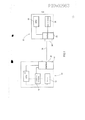
[0012] Passando para a Figura 1, é mostrado um diagrama de bloco de um dispositivo eletrônico móvel conectado a um computador principal de Barramento Serial Universal (USB). O dispositivo eletrônico móvel 10 compreende uma unidade central de processamento (CPU) 12 conectada a uma interface de carregador 14 que, por sua vez, está conectado a uma bateria recarregável 16. A CPU 12 também é conectada à bateria recarregável 16 e à interface USB 18 que é conectada a uma porta USB 20.[0012] Moving on to Figure 1, a block diagram of a mobile electronic device connected to a Universal Serial Bus (USB) main computer is shown. The mobile
[0013] Durante a operação do dispositivo eletrônico móvel 10, quando o usuário determina que a bateria recarregável 16 está arriada ou ausente, o usuário conecta o dispositivo eletrônico móvel 10 ao computador principal USB 22 através de um cabo USB 24. Dentro do cabo USB 24 há quatro cabos separados: uma linha de energia, uma linha de terra, e duas linhas de dados. No computador principal USB 22, o cabo USB é conectado a uma porta do computador principal USB 26. Uma interface de dispositivo 28, preferivelmente uma interface de dispositivo eletrônico móvel, é conectada à porta do computador principal USB 26 para dados e corrente e para receber dados do dispositivo eletrônico móvel 10. O computador principal USB 22 ainda compreende uma fonte de energia 30 e uma CPU 32 que são ambos conectados à interface de dispositivo 28.[0013] During the operation of the mobile
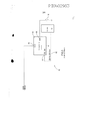
[0014] Passando para a Figura 2, é mostrado um método de comutar entre o estado de suspensão do dispositivo e o estado de carregamento do dispositivo para o dispositivo eletrônico móvel conectado ao Barramento Serial Universal (USB). Para determinar se o dispositivo eletrônico móvel entrou no estado de carregamento do dispositivo, é efetuada uma verificação para sentir se as entradas para a interface do carregador 14 estão em estado baixo. Quando as entradas estão em um estado baixo, a indicação é de que não há energia sendo transferida para a CPU 12 e, portanto, nenhuma energia para operar o dispositivo 10. Como será compreendido, o dispositivo poderá ser desligado, a bateria recarregável 16 está arriada ou ausente ou o usuário poderá ter colocado o dispositivo no modo de suspensão do dispositivo. Portanto, após sentir que as entradas para a interface do carregador foram fixadas em estado baixo, a situação e o nível de uma voltagem de barramento (fornecida pela fonte de energia 30 no computador principal USB) é sentida (etapa 34). A voltagem de barramento é fornecida quando o cabo USB é conectado entre o computador principal USB e o dispositivo eletrônico móvel. Se a voltagem de barramento não é sentida, o supervisor de voltagem continua a monitorar pela presença da voltagem de barramento.[0014] Moving on to Figure 2, a method of switching between the device sleep state and the device charging state for the mobile electronic device connected to the Universal Serial Bus (USB) is shown. To determine whether the mobile electronic device has entered the device charging state, a check is performed to feel if the inputs to the
[0015] Se a voltagem de barramento é sentida, o carregador da bateria é então ativado (etapa 36). Após ativar o carregador da bateria, um cronômetro é então ativado (etapa 38), e fixado para um período de tempo predeterminado, preferivelmente pelo menos 100 ms. Uma vez fixado o cronômetro, ele inicia a contagem regressiva. Uma verificação é então efetuada para verificar se o cronômetro não expirou (etapa 40), isto é, se o período de tempo predeterminado já não decorreu. Se o cronômetro já expirou, o carregador da bateria é então desativado (etapa 42) e o dispositivo retorna à etapa de sentir a voltagem de barramento (etapa 34). Se o cronômetro não expirou, uma verificação é efetuada para determinar se a enumeração entre a CPU e o computador principal USB foi confirmada (etapa 44). Em outras palavras, uma verificação é efetuada para verificar se a CPU transmitiu ou não um sinal solicitando que o carregador da bateria permaneça ativado. Se a enumeração não foi confirmada, a verificação de que o cronômetro não decorreu é efetuada mais uma vez (etapa 40), e a bateria é desativada (etapa 42) quando o cronômetro tiver decorrido.[0015] If the bus voltage is sensed, the battery charger is then activated (step 36). After activating the battery charger, a timer is then activated (step 38), and fixed to a predetermined period of time, preferably at least 100 ms. Once the timer is set, it starts counting down. A check is then carried out to verify that the timer has not expired (step 40), that is, that the predetermined period of time has not already elapsed. If the timer has already expired, the battery charger is then deactivated (step 42) and the device returns to the step of sensing the bus voltage (step 34). If the timer has not expired, a check is performed to determine if the enumeration between the CPU and the USB host has been confirmed (step 44). In other words, a check is performed to check whether or not the CPU has transmitted a signal requesting the battery charger to remain activated. If the enumeration has not been confirmed, the check that the timer has not run is done one more time (step 40), and the battery is deactivated (step 42) when the timer has elapsed.
[0016] Entretanto, se a enumeração foi confirmada dentro do período de tempo predeterminado do envio da situação e do nível da voltagem de barramento, a CPU fixa o dispositivo no estado de carregamento de dispositivo (etapa 46) e tanto energiza a CPU como carrega a bateria utilizando a voltagem de barramento fornecida pela fonte de energia.[0016] However, if the enumeration was confirmed within the predetermined time period of sending the status and bus voltage level, the CPU locks the device into the device loading state (step 46) and both powers the CPU and loads the battery using the bus voltage provided by the power source.
[0017] Passando para a Figura 3, é mostrado um aparelho da tecnologia anterior para lidar com o carregamento do dispositivo ou do estado de suspensão do dispositivo. O aparelho 50 compreende um carregador de bateria 52 conectado através de seu portal Vcc 54 à linha de energia VBUS do computador principal USB 22. Um portal BAT 56 é conectado à CPU 12 juntamente com a bateria recarregável 16. A CPU 12 também é conectada a um portal CE_bar 58 do carregador de bateria 52.[0017] Turning to Figure 3, a prior art apparatus for handling device loading or device sleep state is shown. The
[0018] Quando a bateria está arriada ou ausente, o dispositivo eletrônico móvel 10 é conectado ao computador principal USB 22 (Figura 1), através do cabo USB, para fornecer a voltagem VBUS através da linha de energia. Será compreendido que a bateria recarregável é preferivelmente desacoplada do dispositivo eletrônico móvel 10 para dar partida na CPU 12 e que o reacoplamento poderá ocorrer a qualquer tempo sem afetar a operação do dispositivo desde que a energia é fornecida pela linha de energia VBUS.[0018] When the battery is low or absent, the mobile
[0019] Um sinal de controle do sistema 60 (visto como CHRG_EN_bar) da CPU 12 é transmitido para o carregador da bateria 52 para ativar o carregador quando o VBUS é aplicado. Este sinal é tipicamente um sinal de estado baixo. O aparelho da tecnologia anterior não espera por uma confirmação de enumeração e entra automaticamente no estado de carregamento do dispositivo. Em geral, isto vai contra as especificações USB. Portanto, quando a bateria recarregável 16 está arriada ou ausente e a CPU 12 não tem energia, o sinal CHRG_EN_bar 60 é baixo, e como o carregador requer um sinal de estado baixo ativo para ativar as funções de carregamento, o carregador da bateria 52 ativa e fornece energia (na forma de corrente recebida da linha de energia VBUS) para a CPU 12. Quando o computador principal USB transmite a solicitação de estado de suspensão de dispositivo, o circuito da tecnologia anterior é incapaz de lidar com esta solicitação se a bateria estiver arriada ou ausente.[0019] A system control signal 60 (seen as CHRG_EN_bar) from
[0020] Passando para a Figura 4, é mostrado um diagrama de blocos de uma versão da interface de carregador da Figura 1. A interface de carregador 14 compreende uma entrada 100 da linha de energia VBUS que é conectada a um portal Vcc 102 de um módulo de Supervisor e Restabelecimento de Voltagem 104. Na versão preferida, o módulo de supervisor e de restabelecimento de voltagem 104 é um chip TPS3103 fabricada pela Texas Instruments. O módulo de supervisor e restabelecimento de voltagem 104 também compreende um portal MR_bar 106 e um portal RST_bar 108. A entrada VBUS 100 também é conectada a um portal Vcc 110 de um carregador de bateria 112. O portal RST_bar 108 é conectado a um portal CE_bar 114 do carregador de bateria 112 enquanto o portal BAT 116 do carregador de bateria 112 é conectado à bateria recarregável 16 através da CPU 12. A CPU 12 também é conectada ao portal MR_bar 106 do módulo de supervisor e restabelecimento de voltagem 104 através de um portal NOT (ou inversor) 118. Será compreendido que os sinais que estão sendo recebidos no portal MR_bar 106, no portal RST_bar 108, no portal CE_bar 114 e no portal NOT 118 são entradas binárias de modo que o sinal ou é um sinal em estado baixo (0) ou um sinal em estado alto (1).[0020] Turning to Figure 4, a block diagram of a version of the charger interface of Figure 1 is shown. The
[0021] Em operação, quando a bateria recarregável está arriada ou ausente, para fornecer energia para operação do dispositivo eletrônico móvel 10 (Figura 1), o cabo USB 24 é conectado à porta USB 20 do dispositivo eletrônico móvel 10. Uma vez conectado, o módulo de supervisor e de restabelecimento de voltagem 104 verifica a situação e o nível da entrada 100 da linha de energia VBUS. A verificação é efetuada pelo portal Vcc 102 do módulo de supervisor e de restabelecimento de voltagem 104. Após sentir a presença da entrada 100, um cronômetro 103 dentro do módulo de supervisor e de restabelecimento de voltagem 104 é iniciado para determinar quando um período de tempo predeterminado, conforme descrito acima, já decorreu. O cronômetro 103 poderá ser implementado de um número de formas, digitalmente ou por meio analógico (com um circuito RC, por exemplo). Este período de tempo predeterminado é utilizado para determinar se o dispositivo eletrônico móvel 10 já recebeu uma confirmação de enumeração do computador principal USB 22 para retirar energia do computador principal USB através da linha de energia de entrada VBUS. Uma verificação contínua é efetuada pelo módulo de supervisor e de restabelecimento de voltagem 104 para determinar se o cronômetro já expirou.[0021] In operation, when the rechargeable battery is down or absent, to supply power for operating the mobile electronic device 10 (Figure 1), the
[0022] Durante este período de tempo predeterminado, a CPU 12 é energizada da fonte de energia 30 no computador principal USB. Isto permite que o processo de carregamento tenha início antes da enumeração estar completada. Dentro do período de tempo predeterminado, a CPU 12 é obrigada a enumerar com o computador principal USB 22 para continuar a retirar corrente para energizar o dispositivo 10 e carregar a bateria.[0022] During this predetermined period of time, the
[0023] Após sentir a presença da entrada 100, o módulo de supervisor e de restabelecimento de voltagem 104 transmite um sinal de estado baixo (0) do portal RST_bar 108 para o portal CE_bar 114 do carregador de bateria 112 para ativar o carregador de bateria 112. O carregador de bateria 112 então transmite uma voltagem (corrente) para a CPU 12 e para a bateria recarregável 16 utilizando a corrente recebida no portal Vcc 110 da entrada 100. Uma vez a CPU 12 recebe a corrente, a CPU 12 solicita enumeração da CPU da USB 32 no computador principal USB 22. Uma vez ela recebe uma confirmação de enumeração, a CPU 12 transmite um sinal de estado alto CHRG_EN para o inversor 118 que inverte o sinal para um sinal de estado baixo antes de transmiti-lo para o portal MR_bar 106. Se o sinal de estado baixo não é recebido pelo portal MR_bar 106 antes do final do período de tempo predeterminado, o módulo supervisor e de restabelecimento de voltagem 104 transmite um sinal alto do portal RST_bar 108 para o portal CE_bar 114 para desativar o carregador de bateria 112. Para verificar se o cronômetro está expirado, resultando na desativação do carregador da bateria, o sinal de estado baixo inicial transmitido do módulo de supervisor e de restabelecimento de voltagem 104 para o carregador da bateria, é fixado para o período de tempo predeterminado e uma vez expire o período de tempo, o sinal de estado baixo é comutado para um sinal de estado alto que desativa o carregador da bateria.[0023] After sensing the presence of
[0024] Contudo, se a enumeração é confirmada antes da expiração do cronômetro, o módulo de supervisor e de restabelecimento de voltagem 104 transmite um sinal de estado baixo para o portal CE_bar 114 e o carregador de bateria 112 permanece ativado de modo a receber a entrada 100 e suprir a corrente necessária para energizar o dispositivo eletrônico móvel 10 e para carregar a bateria 16.[0024] However, if the enumeration is confirmed before the expiration of the timer, the supervisor and
[0025] A ativação do carregador de bateria 112 continua até que o cabo USB é desconectado da porta USB 20 ou se um sinal de suspensão de dispositivo é transmitido ao longo das linhas de dados do cabo USB 24 da CPU da USB 32 para a CPU 12 do dispositivo eletrônico móvel 10, indicando que o computador principal USB 22 solicita que o dispositivo eletrônico móvel 10 entre no estado de suspensão de dispositivo. Após receber a solicitação, para cumprir com as especificações USB, a CPU 12 transmite um sinal de estado baixo CHRG_EN para o inversor 118 que inverte o sinal de estado baixo para um sinal de estado alto. O sinal de estado alto é então transmitido para o portal MR_bar 106 que faz com que o portal RST_bar 108 transmita um sinal alto para o portal CE_bar 114 do carregador de bateria, assim desativando o carregador de bateria conforme solicitado pelo computador principal USB 22.[0025] Activation of
[0026] Quando o sinal de estado alto é recebido pelo portal MR_bar 106, o sinal não é propagado imediatamente. O cronômetro 103 faz uma contagem regressiva por um segundo período de tempo predeterminado, como 150 ms, de modo que se um sinal de estado baixo subseqüente é recebido pelo portal MR_bar dentro do segundo período de tempo, o sinal de estado alto é ignorado. Isto permite que a CPU 12 se restabeleça sem perder energia para o carregador de bateria 112. Em geral, quando a CPU se restabelece, todos os sinais vão para um estado baixo. Desta maneira, o evento de restabelecimento não faz com que o carregador seja desativado pois o evento de restabelecimento não é um evento de estado de suspensão de dispositivo.[0026] When the high state signal is received by the
[0027] Uma vantagem da presente invenção é que se a CPU 12 deixa de receber a conformação de enumeração para ativar o carregador de bateria 112 antes do decurso do cronômetro de período de tempo predeterminado, o carregador de bateria é automaticamente desativado. Portanto, o dispositivo eletrônico móvel 10 não continua a retirar energia da fonte de energia 30 no computador principal USB 22. Isto fornece uma função adicional de modo que a CPU 12 do dispositivo eletrônico móvel não retira inadvertentemente corrente sem uma enumeração apropriada.[0027] An advantage of the present invention is that if the
[0028] Outra vantagem da presente invenção é que quando a CPU 12 no dispositivo eletrônico móvel 10 é instruída pela CPU 32 no computador principal USB 22 para entrar no estado de suspensão de dispositivo, a CPU 12 desativa o carregador de bateria 112 ao transmitir o sinal de estado baixo para o inversor 118 e que é subseqüentemente transmitido como um sinal de estado alto para o portal MR_bar do módulo de supervisor e de restabelecimento de voltagem. Se o cronômetro 103 já expirou, e não há mudança da entrada da linha de energia VBUS, o carregador de bateria é desativado embora o VBUS ainda esteja presente conforme necessário pelas especificações USB. Quando o carregador de bateria é desativado, e a bateria recarregável 16 não está inteiramente recarregada, não há energia transmitida para a CPU 12 e embora todos os sinais de estado estejam ativos no estado baixo, os sinais não fazem com que o carregador de bateria seja ativado como foi a situação com a conexão de cabo USB inicial.[0028] Another advantage of the present invention is that when
[0029] Ademais, outra vantagem da presente invenção é que apenas um sinal é necessário para comutar o dispositivo eletrônico móvel do estado de carregamento de dispositivo para o estado de suspensão do dispositivo.[0029] Furthermore, another advantage of the present invention is that only one signal is needed to switch the mobile electronic device from the device charging state to the device sleep state.
[0030] As versões descritas acima da presente invenção pretendem ser apenas exemplos. Alterações, modificações e variações poderão ser efetuadas nas versões particulares por aqueles de habilidade na tecnologia sem desviar do escopo da invenção, que é definido unicamente pelas reivindicações aqui apensadas.[0030] The versions described above of the present invention are intended to be examples only. Changes, modifications and variations may be made to the particular versions by those of skill in the technology without departing from the scope of the invention, which is defined solely by the claims appended hereto.
Claims (11)
Applications Claiming Priority (2)
| Application Number | Priority Date | Filing Date | Title |
|---|---|---|---|
| GB0312079A GB2402271B (en) | 2003-05-27 | 2003-05-27 | Method and apparatus for handling a charging state in a mobile electronic device |
| GB0312079.7 | 2003-05-27 |
Publications (2)
| Publication Number | Publication Date |
|---|---|
| BRPI0402983A BRPI0402983A (en) | 2005-01-25 |
| BRPI0402983B1 true BRPI0402983B1 (en) | 2021-07-27 |
Family
ID=9958789
Family Applications (1)
| Application Number | Title | Priority Date | Filing Date |
|---|---|---|---|
| BRPI0402983-6A BRPI0402983B1 (en) | 2003-05-27 | 2004-05-27 | MOBILE ELECTRONIC DEVICE AND METHOD FOR CHARGING A MOBILE ELECTRONIC DEVICE FROM A MAIN UNIVERSAL SERIAL BUS (USB) COMPUTER |
Country Status (11)
| Country | Link |
|---|---|
| US (5) | US7518343B2 (en) |
| EP (1) | EP1482619B1 (en) |
| JP (2) | JP3908753B2 (en) |
| KR (1) | KR100811025B1 (en) |
| CN (1) | CN100369349C (en) |
| BR (1) | BRPI0402983B1 (en) |
| CA (1) | CA2468388C (en) |
| GB (1) | GB2402271B (en) |
| HK (2) | HK1071234A1 (en) |
| SG (1) | SG116561A1 (en) |
| TW (1) | TWI256237B (en) |
Families Citing this family (82)
| Publication number | Priority date | Publication date | Assignee | Title |
|---|---|---|---|---|
| GB2402271B (en) * | 2003-05-27 | 2006-04-19 | Research In Motion Ltd | Method and apparatus for handling a charging state in a mobile electronic device |
| WO2005078554A1 (en) * | 2004-02-17 | 2005-08-25 | Research In Motion Limited | Method and apparatus for handling a charging state in a mobile electronic device |
| US7679316B2 (en) * | 2004-02-17 | 2010-03-16 | Research In Motion Limited | Method and apparatus for controlling a charging state in a mobile electronic device |
| US20050289257A1 (en) * | 2004-06-24 | 2005-12-29 | Fink Thomas M | Self-powered USB device with USB power line reset and related USB host and USB system |
| US7711039B2 (en) * | 2005-04-01 | 2010-05-04 | Freescale Semiconductor, Inc. | System and method for protecting low voltage transceiver |
| US20060244422A1 (en) * | 2005-04-27 | 2006-11-02 | Digiovanna Robert W | Methods and apparatus for charging a power source |
| KR101201121B1 (en) * | 2005-12-02 | 2012-11-13 | 에스케이이노베이션 주식회사 | Apparatus and method of testing for battery |
| US7701173B2 (en) * | 2005-12-13 | 2010-04-20 | Research In Motion Limited | Charging and power supply for mobile devices |
| US7698490B2 (en) * | 2005-12-21 | 2010-04-13 | Nvidia Corporation | Passive USB power configuration switching |
| US7723951B2 (en) | 2006-06-30 | 2010-05-25 | Intel Corporation | Battery charging apparatus having a chute and method of recharging a battery |
| US7624202B2 (en) * | 2006-08-17 | 2009-11-24 | Standard Microsystems Corporation | System and method for enumerating a USB device using low power |
| US7631111B2 (en) * | 2006-08-17 | 2009-12-08 | Standard Microsystems Corporation | System method for rapidly charging USB device's battery wherein USB device requests charging the battery at a higher power level |
| EP2073337A1 (en) * | 2006-10-11 | 2009-06-24 | Panasonic Corporation | Electronic device and charging control method |
| WO2008046077A2 (en) * | 2006-10-13 | 2008-04-17 | Newton Peripherals Llc | Peripheral devices for portable computer |
| US9235249B2 (en) * | 2006-11-30 | 2016-01-12 | Nokia Technologies Oy | Power control for serial bus peripheral device |
| WO2008068552A1 (en) * | 2006-12-08 | 2008-06-12 | Nokia Corporation | Multiple connections to a single serial interface |
| ES2666490T3 (en) * | 2007-03-29 | 2018-05-04 | Nokia Technologies Oy | Connection to a USB device |
| KR20090028196A (en) * | 2007-09-14 | 2009-03-18 | 삼성전자주식회사 | Apparatus and method for charging in mobile phone |
| US8390146B2 (en) * | 2008-02-27 | 2013-03-05 | Panasonic Corporation | Semiconductor integrated circuit and various devices provided with the same |
| CN101546918B (en) * | 2008-03-25 | 2012-05-30 | 鸿富锦精密工业(深圳)有限公司 | Device and method for charging USB |
| US8185759B1 (en) | 2008-11-06 | 2012-05-22 | Smsc Holdings S.A.R.L. | Methods and systems for interfacing bus powered devices with host devices providing limited power levels |
| US7882297B2 (en) * | 2009-02-20 | 2011-02-01 | Standard Microsystems Corporation | Serial bus hub with low power devices |
| CN101827162B (en) * | 2009-03-04 | 2013-08-07 | 深圳富泰宏精密工业有限公司 | Mobile phone USB interface detection system and method |
| CN101853966B (en) * | 2009-03-31 | 2013-10-16 | 联芯科技有限公司 | USB charging method and device for handheld terminal |
| TWI390818B (en) * | 2009-07-14 | 2013-03-21 | Richpower Microelectronics | Apparatus and method for improving the standby efficiency of a charger, and ultra low standby power charge |
| TWI398759B (en) | 2009-07-22 | 2013-06-11 | Htc Corp | Power supply device, portable electronic apparatus and related method for determining types of a power supply device |
| CN101989751B (en) * | 2009-07-30 | 2014-01-15 | 宏达国际电子股份有限公司 | Power supply device, portable electronic device and related judgment method |
| CN101728859B (en) * | 2009-12-17 | 2012-12-19 | 中兴通讯股份有限公司 | Mobile terminals and system and method for sharing batteries between same |
| JP5645438B2 (en) * | 2010-03-25 | 2014-12-24 | キヤノン株式会社 | Power supply apparatus and power supply method |
| US8826051B2 (en) * | 2010-07-26 | 2014-09-02 | Apple Inc. | Dynamic allocation of power budget to a system having non-volatile memory and a processor |
| JP5812502B2 (en) * | 2010-08-24 | 2015-11-17 | マーベル ワールド トレード リミテッド | Device interface and apparatus |
| JP5634608B2 (en) | 2010-09-02 | 2014-12-03 | ヒューレット−パッカード デベロップメント カンパニー エル.ピー.Hewlett‐Packard Development Company, L.P. | Charging port |
| KR101717505B1 (en) * | 2010-12-02 | 2017-03-17 | 삼성전자주식회사 | Method for Charging External Device and Displaying Apparatus using thereof |
| US9436479B2 (en) | 2011-01-17 | 2016-09-06 | Qualcomm Incorporated | Booting a mobile electronic device with a low battery based on a dynamic boot threshold |
| US8996771B1 (en) * | 2011-05-09 | 2015-03-31 | Google Inc. | System and method for communication via universal serial bus |
| US8332545B1 (en) | 2011-05-31 | 2012-12-11 | Smsc Holdings S.A.R.L. | USB switch which allows primary USB connection in response to USB signaling |
| CN102403754A (en) * | 2011-06-30 | 2012-04-04 | 宣建民 | Power supply adapter with cruising ability |
| US8788852B2 (en) * | 2011-07-01 | 2014-07-22 | Intel Corporation | System and method for providing power through a reverse local data transfer connection |
| US8598850B2 (en) | 2011-08-30 | 2013-12-03 | Perumala Corporation | Devices and methods for optimizing rechargeable battery life |
| US8816644B2 (en) | 2011-08-30 | 2014-08-26 | Perumala Corporation | Interrupting the charging status of a rechargeable battery |
| US8843770B2 (en) | 2011-10-31 | 2014-09-23 | Smsc Holdings S.A.R.L. | Device charging over USB using a plurality of handshakes |
| KR20130122266A (en) * | 2012-04-30 | 2013-11-07 | 삼성전자주식회사 | System and apparatus and method for performing charging in host mode |
| US9092101B2 (en) | 2012-06-26 | 2015-07-28 | Google Technology Holdings LLC | Battery charging interrupt |
| US9395799B2 (en) | 2012-08-09 | 2016-07-19 | Nvidia Corporation | Power management techniques for USB interfaces |
| JP6288913B2 (en) | 2012-12-28 | 2018-03-07 | キヤノン株式会社 | Electronic device and program |
| JP6164857B2 (en) | 2013-02-12 | 2017-07-19 | キヤノン株式会社 | Power feeding device, power feeding device control method, power receiving device, power receiving device control method, program |
| US11797469B2 (en) | 2013-05-07 | 2023-10-24 | Snap-On Incorporated | Method and system of using USB user interface in electronic torque wrench |
| CN104423278B (en) | 2013-08-27 | 2017-09-26 | 华为终端有限公司 | Mobile power supply terminal and its method of supplying power to |
| CN103491248B (en) * | 2013-09-16 | 2016-01-20 | 华为技术有限公司 | A kind of method of low electricity start and subscriber equipment |
| USD757649S1 (en) | 2013-12-19 | 2016-05-31 | Perumala Corporation | Adapter |
| CN109308111B (en) * | 2014-05-28 | 2022-03-01 | 精工爱普生株式会社 | Electronic device |
| JP6277866B2 (en) * | 2014-05-28 | 2018-02-14 | セイコーエプソン株式会社 | Charging device and electronic device |
| US20160061173A1 (en) * | 2014-08-27 | 2016-03-03 | General Electric Company | System and method for determining health of an engine-generator set |
| WO2016161454A1 (en) | 2015-04-03 | 2016-10-06 | Pinn, Inc. | Personal wireless media station |
| JP2017045086A (en) | 2015-08-24 | 2017-03-02 | キヤノン株式会社 | Electronic apparatus and control method |
| JP6532357B2 (en) * | 2015-08-31 | 2019-06-19 | キヤノン株式会社 | Power transmission device, control method and program |
| CN105302278B (en) * | 2015-10-19 | 2018-08-03 | 广东欧珀移动通信有限公司 | The control method and device and mobile terminal of fingerprint sensor Serial Peripheral Interface (SPI) |
| JP2017085853A (en) * | 2015-10-30 | 2017-05-18 | キヤノン株式会社 | Electronic equipment and method of controlling the same |
| US10483773B2 (en) | 2016-01-28 | 2019-11-19 | Dell Products L.P. | Information handling system external adapter and battery source |
| US10224732B2 (en) * | 2016-01-28 | 2019-03-05 | Dell Products L.P. | Information handling system external adapter and battery source |
| CN105843365A (en) * | 2016-03-24 | 2016-08-10 | 广东欧珀移动通信有限公司 | Sensor control method and device |
| DE102016107271A1 (en) * | 2016-04-20 | 2017-10-26 | Rwe International Se | Charging system and method for operating a charging system |
| CN106506821B (en) * | 2016-10-24 | 2019-10-18 | Oppo广东移动通信有限公司 | The method and mobile terminal of reading data |
| CN106877462B (en) * | 2017-04-21 | 2019-04-12 | 维沃移动通信有限公司 | A kind of method and charger detecting charged state |
| CN107193226B (en) * | 2017-07-11 | 2020-07-17 | 广州飞傲电子科技有限公司 | Control method and system for vehicle-mounted mode of music player |
| US10383482B1 (en) * | 2018-12-31 | 2019-08-20 | Miramore Inc. | Portable and rechargeable blender |
| US10702837B1 (en) | 2019-10-28 | 2020-07-07 | BlendJet, Inc. | Rechargeable blender with offset blades |
| US10828612B1 (en) | 2019-11-25 | 2020-11-10 | Blendjet Inc. | Locking and unlocking a blender |
| USD905496S1 (en) | 2019-11-25 | 2020-12-22 | Blendjet Inc. | Portable blender |
| USD948940S1 (en) | 2019-11-25 | 2022-04-19 | Blendjet Inc. | Base of a portable blender |
| USD953103S1 (en) | 2019-11-26 | 2022-05-31 | Blendjet Inc. | Portable blender lid |
| USD908428S1 (en) | 2019-12-02 | 2021-01-26 | Blendjet Inc. | Removable jar of a portable blender |
| USD911107S1 (en) | 2019-12-09 | 2021-02-23 | Blendjet Inc. | Button and light ring of a portable blender |
| US11531403B2 (en) | 2020-10-06 | 2022-12-20 | Blendjet Inc. | One button interface of a blender |
| USD1007947S1 (en) | 2020-11-20 | 2023-12-19 | Blendjet Inc. | Battery-powered portable blender |
| USD973437S1 (en) | 2020-11-20 | 2022-12-27 | Blendjet Inc. | Lid of a battery-powered portable blender |
| USD981179S1 (en) | 2020-11-20 | 2023-03-21 | Blendjet Inc. | Base of a battery-powered portable blender |
| USD1007948S1 (en) | 2020-11-25 | 2023-12-19 | Blendjet Inc. | Removable jar of a battery-powered portable blender |
| USD1014178S1 (en) | 2020-11-25 | 2024-02-13 | Blendjet Inc. | Battery-powered portable blender |
| US11690482B1 (en) | 2020-12-10 | 2023-07-04 | Blendjet Inc. | Power boost mode for a blender |
| USD974841S1 (en) | 2021-03-08 | 2023-01-10 | Blendjet Inc. | Blade assembly for a portable blender |
| US11824365B2 (en) | 2021-03-08 | 2023-11-21 | Blendjet Inc. | Portable blender with wireless charging |
Family Cites Families (63)
| Publication number | Priority date | Publication date | Assignee | Title |
|---|---|---|---|---|
| US3748386A (en) | 1972-04-03 | 1973-07-24 | D Monney | Time-base error correction system |
| US4568096A (en) | 1984-04-19 | 1986-02-04 | General Motors Corporation | Automatic vehicle level control |
| US5398265A (en) | 1988-11-10 | 1995-03-14 | Hughes Aircraft Company | Computer subsystem reset by address dependent RC discharge |
| US5028859A (en) | 1989-06-05 | 1991-07-02 | Motorola, Inc. | Multiple battery, multiple rate battery charger |
| US5250891A (en) | 1991-05-13 | 1993-10-05 | Milwaukee Electric Tool Corporation | Battery charging method and apparatus |
| US5462439A (en) * | 1993-04-19 | 1995-10-31 | Keith; Arlie L. | Charging batteries of electric vehicles |
| JP2959657B2 (en) * | 1993-05-13 | 1999-10-06 | キヤノン株式会社 | Electronics |
| US6101421A (en) | 1993-09-10 | 2000-08-08 | Motorola, Inc. | Reset recovery in a microprocessor controlled device |
| US5519346A (en) | 1994-06-22 | 1996-05-21 | Motorola, Inc. | Selective restart circuit for an electronic device |
| JP3733554B2 (en) * | 1994-10-31 | 2006-01-11 | 富士通株式会社 | Battery-powered electronic equipment |
| JP2986059B2 (en) * | 1995-03-08 | 1999-12-06 | インターナショナル・ビジネス・マシーンズ・コーポレイション | Battery charger |
| US5712568A (en) * | 1995-09-05 | 1998-01-27 | Ford Motor Company | Battery voltage measurement system |
| US5898290A (en) * | 1995-09-07 | 1999-04-27 | Norand Corporation | Battery pack with capacity and pre-removal indicators |
| JP3439035B2 (en) * | 1996-07-30 | 2003-08-25 | 三洋電機株式会社 | Battery pack to prevent battery over-discharge |
| GB9623612D0 (en) | 1996-11-13 | 1997-01-08 | Rca Thomson Licensing Corp | Separate power supplies for standby operation |
| KR100259263B1 (en) * | 1997-05-21 | 2000-06-15 | 윤종용 | A battery charging circuit of portable computer system and charging method of that |
| KR100258043B1 (en) * | 1997-10-27 | 2000-06-01 | 에릭 발리베 | The control system for the auxiliary power unit of hybrid electrical vehicle |
| US5926006A (en) * | 1997-11-03 | 1999-07-20 | International Business Machines Corporation | Modular electronic apparatus with battery charging control |
| JP2000032684A (en) * | 1998-07-08 | 2000-01-28 | Toyota Autom Loom Works Ltd | Charging circuit and method therefor |
| US6357011B2 (en) | 1998-07-15 | 2002-03-12 | Gateway, Inc. | Bus-powered computer peripheral with supplement battery power to overcome bus-power limit |
| US6262563B1 (en) * | 1998-09-11 | 2001-07-17 | Keith S. Champlin | Method and apparatus for measuring complex admittance of cells and batteries |
| JP2000105638A (en) | 1998-09-29 | 2000-04-11 | Nec Corp | Usb device and usb connection system |
| US6191552B1 (en) * | 1999-01-25 | 2001-02-20 | Dell Usa, L.P. | External universal battery charging apparatus and method |
| SE516285C2 (en) | 1999-01-27 | 2001-12-10 | Ericsson Telefon Ab L M | A method which enables communication between an electronic device and a battery, an apparatus comprising an electronic device and a battery, and a battery which enables communication |
| US6211649B1 (en) | 1999-03-25 | 2001-04-03 | Sourcenext Corporation | USB cable and method for charging battery of external apparatus by using USB cable |
| US6031362A (en) | 1999-05-13 | 2000-02-29 | Bradley; Larry D. | Method and apparatus for feedback control of switch mode power supply output to linear regulators |
| US6153855A (en) | 1999-05-20 | 2000-11-28 | Illinois Tool Works Inc. | Control of weld and auxiliary power output of a generator type welding power supply |
| DE19944053C2 (en) | 1999-09-14 | 2001-08-02 | Infineon Technologies Ag | Device and method for the power supply of computer accessories via the bus system of the computer |
| US6633932B1 (en) | 1999-09-14 | 2003-10-14 | Texas Instruments Incorporated | Method and apparatus for using a universal serial bus to provide power to a portable electronic device |
| US6665801B1 (en) | 2000-01-27 | 2003-12-16 | Symbol Technologies, Inc. | Method and apparatus for charging a self powered USB device at different charge rates according to the charge level of a rechargeable element on the device |
| GB2362769A (en) | 2000-05-26 | 2001-11-28 | Nokia Mobile Phones Ltd | Battery charging circuit in which power is supplied via a communications port |
| US6362599B1 (en) * | 2000-09-21 | 2002-03-26 | Delphi Technologies, Inc. | Method and apparatus for sensing the status of a vehicle |
| TW479393B (en) | 2000-09-27 | 2002-03-11 | Acer Peripherals Inc | Automatic USB charging apparatus and its operating method |
| US6646561B1 (en) * | 2000-10-06 | 2003-11-11 | Battery Alert Ltd. | Method and device for in-use detecting low cranking strength of a combustion engine battery during engine starting |
| US6883715B1 (en) | 2000-10-11 | 2005-04-26 | Stmicroelectronics, Inc. | Multi-mode smart card, system and associated methods |
| EP1198049A1 (en) | 2000-10-12 | 2002-04-17 | Sony International (Europe) GmbH | Charging circuit for charging a mobile terminal through an USB interface |
| WO2002071734A2 (en) | 2000-12-19 | 2002-09-12 | Smal Camera Technologies, Inc. | Compact digital camera system |
| US6936936B2 (en) * | 2001-03-01 | 2005-08-30 | Research In Motion Limited | Multifunctional charger system and method |
| CA2517333C (en) * | 2001-03-01 | 2007-11-27 | Research In Motion Limited | System and method for powering and charging a mobile communication device |
| US6507172B2 (en) | 2001-03-19 | 2003-01-14 | Maxim Integrated Products, Inc. | Universal serial bus powered battery charger |
| US6531854B2 (en) | 2001-03-30 | 2003-03-11 | Champion Microelectronic Corp. | Power factor correction circuit arrangement |
| US6853259B2 (en) | 2001-08-15 | 2005-02-08 | Gallitzin Allegheny Llc | Ring oscillator dynamic adjustments for auto calibration |
| US6812971B2 (en) | 2001-09-11 | 2004-11-02 | Olympus Optical Co., Ltd. | Electronic apparatus, stand and electronic apparatus stand system |
| TW529243B (en) * | 2001-10-22 | 2003-04-21 | Winbond Electronics Corp | Power initiation apparatus of peripheral device |
| US20030110403A1 (en) | 2001-12-10 | 2003-06-12 | Intel Corporation | System for shared power supply in computer peripheral devices |
| TW543994U (en) | 2001-12-25 | 2003-07-21 | Sheng-Shing Liau | Easy carrying multi-function charger |
| JP3904489B2 (en) | 2002-07-04 | 2007-04-11 | 富士通株式会社 | Charge control circuit, charger, power supply circuit, information processing apparatus, and battery pack |
| JP3654274B2 (en) * | 2002-08-30 | 2005-06-02 | セイコーエプソン株式会社 | Data transfer control device, electronic device, and power supply switching method |
| US6650089B1 (en) | 2002-10-16 | 2003-11-18 | Texas Instruments Incorporated | Control circuit for multiple battery systems with capacity gauge on end equipment |
| US7791319B2 (en) * | 2003-02-21 | 2010-09-07 | Research In Motion Limited | Circuit and method of operation for an electrical power supply |
| US6833686B2 (en) | 2003-02-21 | 2004-12-21 | Research In Motion Limited | Circuit and method of operation for an adaptive charge rate power supply |
| GB2402271B (en) | 2003-05-27 | 2006-04-19 | Research In Motion Ltd | Method and apparatus for handling a charging state in a mobile electronic device |
| GB2402819B (en) | 2003-06-11 | 2005-08-03 | Research In Motion Ltd | Universal serial bus charger for a mobile device |
| US7679316B2 (en) | 2004-02-17 | 2010-03-16 | Research In Motion Limited | Method and apparatus for controlling a charging state in a mobile electronic device |
| WO2005078554A1 (en) | 2004-02-17 | 2005-08-25 | Research In Motion Limited | Method and apparatus for handling a charging state in a mobile electronic device |
| JP4155978B2 (en) * | 2004-03-30 | 2008-09-24 | 三洋電機株式会社 | Power supply |
| US20060043933A1 (en) * | 2004-08-31 | 2006-03-02 | Latinis Gary R | Battery voltage monitor |
| US7696717B2 (en) * | 2005-08-08 | 2010-04-13 | Continental Automotive Systems Us, Inc. | Battery energy management system for measuring a minimum battery voltage |
| US7750501B2 (en) * | 2005-10-27 | 2010-07-06 | Continental Automotive Systems Us, Inc. | System and method of over voltage control for a power system |
| US7602143B2 (en) * | 2005-11-04 | 2009-10-13 | Peter David Capizzo | System for replenishing energy sources onboard different types of automotive vehicles |
| JP4944654B2 (en) * | 2007-03-30 | 2012-06-06 | キヤノン株式会社 | Power supply device and recording device |
| US20110050164A1 (en) * | 2008-05-07 | 2011-03-03 | Afshin Partovi | System and methods for inductive charging, and improvements and uses thereof |
| US20110066515A1 (en) * | 2009-09-16 | 2011-03-17 | Horvath Ronald F | Automated electric plug-in station for charging electric and hybrid vehicles |
-
2003
- 2003-05-27 GB GB0312079A patent/GB2402271B/en not_active Expired - Lifetime
-
2004
- 2004-05-25 SG SG200405773A patent/SG116561A1/en unknown
- 2004-05-25 US US10/852,781 patent/US7518343B2/en active Active
- 2004-05-26 EP EP04012446A patent/EP1482619B1/en active Active
- 2004-05-27 TW TW093115115A patent/TWI256237B/en not_active IP Right Cessation
- 2004-05-27 KR KR1020040037705A patent/KR100811025B1/en active IP Right Grant
- 2004-05-27 JP JP2004158375A patent/JP3908753B2/en not_active Expired - Fee Related
- 2004-05-27 CN CNB200410048812XA patent/CN100369349C/en active Active
- 2004-05-27 CA CA002468388A patent/CA2468388C/en active Active
- 2004-05-27 BR BRPI0402983-6A patent/BRPI0402983B1/en not_active IP Right Cessation
-
2005
- 2005-02-12 HK HK05101126.0A patent/HK1071234A1/en not_active IP Right Cessation
- 2005-05-31 HK HK05104576A patent/HK1073508A1/en not_active IP Right Cessation
-
2006
- 2006-08-22 JP JP2006225446A patent/JP4144891B2/en not_active Expired - Fee Related
-
2009
- 2009-04-07 US US12/419,897 patent/US7768239B2/en active Active
-
2010
- 2010-07-23 US US12/842,763 patent/US7893660B2/en active Active
-
2011
- 2011-02-21 US US13/031,493 patent/US8283897B2/en active Active
-
2012
- 2012-10-04 US US13/645,152 patent/US8610407B2/en active Active
Also Published As
| Publication number | Publication date |
|---|---|
| HK1073508A1 (en) | 2005-10-07 |
| TW200511813A (en) | 2005-03-16 |
| EP1482619A2 (en) | 2004-12-01 |
| TWI256237B (en) | 2006-06-01 |
| KR100811025B1 (en) | 2008-03-11 |
| GB2402271B (en) | 2006-04-19 |
| GB2402271A (en) | 2004-12-01 |
| US7768239B2 (en) | 2010-08-03 |
| US20130033226A1 (en) | 2013-02-07 |
| EP1482619B1 (en) | 2012-05-23 |
| JP4144891B2 (en) | 2008-09-03 |
| EP1482619A3 (en) | 2005-07-27 |
| US20110140674A1 (en) | 2011-06-16 |
| US20040239294A1 (en) | 2004-12-02 |
| CN1574539A (en) | 2005-02-02 |
| BRPI0402983A (en) | 2005-01-25 |
| CA2468388C (en) | 2009-09-01 |
| JP2007020398A (en) | 2007-01-25 |
| JP2004357497A (en) | 2004-12-16 |
| JP3908753B2 (en) | 2007-04-25 |
| US8283897B2 (en) | 2012-10-09 |
| US7518343B2 (en) | 2009-04-14 |
| US8610407B2 (en) | 2013-12-17 |
| SG116561A1 (en) | 2005-11-28 |
| US20100289456A1 (en) | 2010-11-18 |
| US20090200989A1 (en) | 2009-08-13 |
| HK1071234A1 (en) | 2005-07-08 |
| CA2468388A1 (en) | 2004-11-27 |
| GB0312079D0 (en) | 2003-07-02 |
| CN100369349C (en) | 2008-02-13 |
| US7893660B2 (en) | 2011-02-22 |
| KR20040102341A (en) | 2004-12-04 |
Similar Documents
| Publication | Publication Date | Title |
|---|---|---|
| BRPI0402983B1 (en) | MOBILE ELECTRONIC DEVICE AND METHOD FOR CHARGING A MOBILE ELECTRONIC DEVICE FROM A MAIN UNIVERSAL SERIAL BUS (USB) COMPUTER | |
| US8111040B2 (en) | Method and apparatus for handling a charging state in a mobile electronic device | |
| US7679316B2 (en) | Method and apparatus for controlling a charging state in a mobile electronic device | |
| EP0889387B1 (en) | Controlling a power state of a computer | |
| KR920002245B1 (en) | Portable computer operated by batteries | |
| US10891062B2 (en) | Managing host communication with a regulator in a low power mode | |
| KR20000069495A (en) | Method and apparatus for supporting power conservation operation modes | |
| JPH0833790B2 (en) | Power shutdown device for computer | |
| US11385904B2 (en) | Methods and apparatus for selecting operating modes in a device | |
| JPH05297983A (en) | System operation protective device for electronic equipment with packaging mechanism for hard disk pack |
Legal Events
| Date | Code | Title | Description |
|---|---|---|---|
| B08F | Application dismissed because of non-payment of annual fees [chapter 8.6 patent gazette] |
Free format text: REFERENTE AS 5A, 6A E 7A ANUIDADES. |
|
| B08G | Application fees: restoration [chapter 8.7 patent gazette] | ||
| B25D | Requested change of name of applicant approved |
Owner name: BLACKBERRY LIMITED (CA) |
|
| B25G | Requested change of headquarter approved |
Owner name: BLACKBERRY LIMITED (CA) |
|
| B07A | Application suspended after technical examination (opinion) [chapter 7.1 patent gazette] | ||
| B09B | Patent application refused [chapter 9.2 patent gazette] |
Free format text: INDEFIRO O PEDIDO DE ACORDO COM O ART .8O COMBINADO COM ART. 13 DA LPI |
|
| B12B | Appeal against refusal [chapter 12.2 patent gazette] | ||
| B25A | Requested transfer of rights approved |
Owner name: FUNDAMENTAL INNOVATION SYSTEMS INTERNATIONAL LLC ( |
|
| B25G | Requested change of headquarter approved |
Owner name: FUNDAMENTAL INNOVATION SYSTEMS INTERNATIONAL LLC ( |
|
| B16A | Patent or certificate of addition of invention granted [chapter 16.1 patent gazette] |
Free format text: PRAZO DE VALIDADE: 20 (VINTE) ANOS CONTADOS A PARTIR DE 27/05/2004, OBSERVADAS AS CONDICOES LEGAIS. PATENTE CONCEDIDA CONFORME ADI 5.529/DF, QUE DETERMINA A ALTERACAO DO PRAZO DE CONCESSAO. |
|
| B21F | Lapse acc. art. 78, item iv - on non-payment of the annual fees in time |
Free format text: REFERENTE A 20A ANUIDADE. |