BR112018067578B1 - ROTARY CUTTING TOOL AND TOOL HOLDER - Google Patents
ROTARY CUTTING TOOL AND TOOL HOLDER Download PDFInfo
- Publication number
- BR112018067578B1 BR112018067578B1 BR112018067578-4A BR112018067578A BR112018067578B1 BR 112018067578 B1 BR112018067578 B1 BR 112018067578B1 BR 112018067578 A BR112018067578 A BR 112018067578A BR 112018067578 B1 BR112018067578 B1 BR 112018067578B1
- Authority
- BR
- Brazil
- Prior art keywords
- internal thread
- thread
- internal
- axis
- external
- Prior art date
Links
Images


Classifications
-
- B—PERFORMING OPERATIONS; TRANSPORTING
- B23—MACHINE TOOLS; METAL-WORKING NOT OTHERWISE PROVIDED FOR
- B23C—MILLING
- B23C5/00—Milling-cutters
- B23C5/26—Securing milling cutters to the driving spindle
-
- B—PERFORMING OPERATIONS; TRANSPORTING
- B23—MACHINE TOOLS; METAL-WORKING NOT OTHERWISE PROVIDED FOR
- B23C—MILLING
- B23C5/00—Milling-cutters
- B23C5/02—Milling-cutters characterised by the shape of the cutter
- B23C5/10—Shank-type cutters, i.e. with an integral shaft
-
- B—PERFORMING OPERATIONS; TRANSPORTING
- B23—MACHINE TOOLS; METAL-WORKING NOT OTHERWISE PROVIDED FOR
- B23B—TURNING; BORING
- B23B31/00—Chucks; Expansion mandrels; Adaptations thereof for remote control
- B23B31/02—Chucks
- B23B31/10—Chucks characterised by the retaining or gripping devices or their immediate operating means
- B23B31/11—Retention by threaded connection
- B23B31/1107—Retention by threaded connection for conical parts
- B23B31/1115—Retention by threaded connection for conical parts using conical threads
-
- B—PERFORMING OPERATIONS; TRANSPORTING
- B23—MACHINE TOOLS; METAL-WORKING NOT OTHERWISE PROVIDED FOR
- B23B—TURNING; BORING
- B23B31/00—Chucks; Expansion mandrels; Adaptations thereof for remote control
- B23B31/02—Chucks
- B23B31/10—Chucks characterised by the retaining or gripping devices or their immediate operating means
- B23B31/11—Retention by threaded connection
- B23B31/1107—Retention by threaded connection for conical parts
- B23B31/1122—Retention by threaded connection for conical parts using cylindrical threads
-
- B—PERFORMING OPERATIONS; TRANSPORTING
- B23—MACHINE TOOLS; METAL-WORKING NOT OTHERWISE PROVIDED FOR
- B23C—MILLING
- B23C5/00—Milling-cutters
- B23C5/02—Milling-cutters characterised by the shape of the cutter
- B23C5/10—Shank-type cutters, i.e. with an integral shaft
- B23C5/109—Shank-type cutters, i.e. with an integral shaft with removable cutting inserts
-
- B—PERFORMING OPERATIONS; TRANSPORTING
- B23—MACHINE TOOLS; METAL-WORKING NOT OTHERWISE PROVIDED FOR
- B23C—MILLING
- B23C5/00—Milling-cutters
- B23C5/16—Milling-cutters characterised by physical features other than shape
- B23C5/20—Milling-cutters characterised by physical features other than shape with removable cutter bits or teeth or cutting inserts
- B23C5/22—Securing arrangements for bits or teeth or cutting inserts
- B23C5/24—Securing arrangements for bits or teeth or cutting inserts adjustable
- B23C5/2472—Securing arrangements for bits or teeth or cutting inserts adjustable the adjusting means being screws
-
- B—PERFORMING OPERATIONS; TRANSPORTING
- B23—MACHINE TOOLS; METAL-WORKING NOT OTHERWISE PROVIDED FOR
- B23C—MILLING
- B23C2210/00—Details of milling cutters
- B23C2210/02—Connections between the shanks and detachable cutting heads
-
- B—PERFORMING OPERATIONS; TRANSPORTING
- B23—MACHINE TOOLS; METAL-WORKING NOT OTHERWISE PROVIDED FOR
- B23C—MILLING
- B23C2210/00—Details of milling cutters
- B23C2210/03—Cutting heads comprised of different material than the shank irrespective of whether the head is detachable from the shank
-
- B—PERFORMING OPERATIONS; TRANSPORTING
- B23—MACHINE TOOLS; METAL-WORKING NOT OTHERWISE PROVIDED FOR
- B23C—MILLING
- B23C2240/00—Details of connections of tools or workpieces
- B23C2240/32—Connections using screw threads
-
- B—PERFORMING OPERATIONS; TRANSPORTING
- B23—MACHINE TOOLS; METAL-WORKING NOT OTHERWISE PROVIDED FOR
- B23C—MILLING
- B23C2265/00—Details of general geometric configurations
- B23C2265/08—Conical
Landscapes
- Engineering & Computer Science (AREA)
- Mechanical Engineering (AREA)
- Milling Processes (AREA)
Abstract
Uma ferramenta de corte rotativa (20) inclui uma cabeça de corte substituível (22) e um suporte para ferramenta (24). A cabeça de corte substituível (22) inclui uma porção de corte dianteira (26) e uma porção de montagem traseira (28). A porção de montagem (28) inclui um membro de acoplamento macho (38) que inclui uma rosca externa reta (42). O suporte para ferramenta (24) inclui um membro de acoplamento fêmea (68) que inclui uma rosca interna cônica (72). Quando a ferramenta de corte rotativa (20) está em uma posição travada, a rosca externa (42) é engatada de modo rosqueado com a rosca interna (72).A rotary cutting tool (20) includes a replaceable cutting head (22) and tool holder (24). The replaceable cutting head (22) includes a front cutting portion (26) and a rear mounting portion (28). The mounting portion (28) includes a male coupling member (38) that includes a straight external thread (42). The tool holder (24) includes a female coupling member (68) that includes a tapered internal thread (72). When the rotary cutting tool (20) is in a locked position, the external thread (42) is threadably engaged with the internal thread (72).
Description
[001] A matéria do presente pedido se refere a ferramentas de corte rotativas do tipo em que uma cabeça de corte substituível, tendo um membro de acoplamento macho, é retida de modo removível em um membro de acoplamento fêmea, de um suporte para ferramenta, por meio de um mecanismo de acoplamento rosqueado[001] The subject of the present application relates to rotary cutting tools of the type in which a replaceable cutting head, having a male coupling member, is removablely retained in a female coupling member, of a tool holder, via a threaded coupling mechanism
[002] As ferramentas de corte rotativas podem ser providas com um mecanismo de acoplamento rosqueado, ou “junta de ferramenta”, para reter com segurança uma cabeça de corte substituível dentro de um suporte para ferramenta.[002] Rotary cutting tools may be provided with a threaded coupling mechanism, or “tool joint”, to securely retain a replaceable cutting head within a tool holder.
[003] A cabeça de corte substituível pode incluir um membro de acoplamento macho e o suporte para ferramenta pode incluir um membro de acoplamento fêmea. O membro de acoplamento macho pode incluir uma rosca externa. O membro de acoplamento fêmea pode incluir uma rosca interna que corresponde à rosca externa no membro de acoplamento macho.[003] The replaceable cutting head may include a male coupling member and the tool holder may include a female coupling member. The male coupling member may include an external thread. The female coupling member may include an internal thread that matches the external thread on the male coupling member.
[004] Em algumas dessas ferramentas de corte rotativas, as roscas internas e externas são ambas roscas retas. Um exemplo de uma tal ferramenta de corte rotativa é descrito, por exemplo, no documento n° U.S. 6.485.220.[004] In some of these rotary cutting tools, the internal and external threads are both straight threads. An example of such a rotary cutting tool is described, for example, in document no. U.S. 6,485,220.
[005] Em outras ferramentas de corte rotativas, as roscas interna e externa são ambas roscas afiladas. Exemplos de tal ferramenta de corte rotativa são descritos, por exemplo, no documento n° U.S. 7.611.311 e no documento n° U.S. 7.713.004.[005] In other rotary cutting tools, the internal and external threads are both tapered threads. Examples of such a rotary cutting tool are described, for example, in document no. U.S. 7,611,311 and in document No. U.S. 7,713,004.
[006] De acordo com um primeiro aspecto da matéria do presente pedido, é provida uma ferramenta de corte rotativa com um eixo geométrico longitudinal que se estende em uma direção dianteira para a traseira, compreendendo: um suporte para ferramenta, tendo um eixo geométrico longitudinal de suporte e compreendendo um membro de acoplamento fêmea tendo uma rosca interna que se estende para a traseira a partir de uma superfície dianteira de suporte, a superfície dianteira de suporte se estendendo transversalmente em relação ao eixo geométrico longitudinal de suporte; e uma cabeça de corte substituível com um eixo geométrico longitudinal de cabeça e compreendendo: uma porção dianteira formando uma porção de corte; e uma porção traseira formando uma porção de montagem, a porção de montagem compreendendo um membro de acoplamento macho tendo uma rosca externa e se projetando para a traseira a partir de uma superfície da base de cabeça, a superfície da base de cabeça se estendendo transversalmente em relação ao eixo geométrico longitudinal de cabeça e definindo um contorno entre a porção de corte e a porção de montagem; em que: a rosca externa do membro de acoplamento macho é uma rosca reta; a rosca interna do membro de acoplamento fêmea é uma rosca cônica; e a ferramenta de corte rotativa é ajustável entre: uma posição liberada na qual o membro de acoplamento macho está localizado do lado de fora do membro de acoplamento fêmea, e as roscas interna e externa não estão engatadas de modo rosqueado uma à outra, e uma posição travada na qual o membro de acoplamento macho é retido de modo removível no membro de acoplamento fêmea com as roscas interna e externa engatadas de modo rosqueado uma à outra.[006] According to a first aspect of the subject matter of the present application, a rotary cutting tool is provided with a longitudinal axis extending in a front to rear direction, comprising: a tool holder, having a longitudinal axis support and comprising a female coupling member having an internal thread extending rearwardly from a support front surface, the support front surface extending transversely to the support longitudinal axis; and a replaceable cutting head having a longitudinal head axis and comprising: a forward portion forming a cutting portion; and a rear portion forming a mounting portion, the mounting portion comprising a male coupling member having an external thread and projecting rearwardly from a surface of the head base, the surface of the head base extending transversely across relative to the head longitudinal axis and defining a contour between the cutting portion and the assembly portion; where: the external thread of the male coupling member is a straight thread; the internal thread of the female coupling member is a tapered thread; and the rotary cutting tool is adjustable between: a released position in which the male coupling member is located outside the female coupling member, and the internal and external threads are not threadably engaged with each other, and a locked position in which the male coupling member is releasably retained in the female coupling member with the internal and external threads threadably engaged with each other.
[007] De acordo com outro aspecto da matéria do presente pedido, é provido um suporte para ferramenta, tendo um eixo geométrico longitudinal de suporte se estendendo na direção dianteira para traseira, compreendendo um membro de acoplamento fêmea tendo uma rosca interna se estendendo para a traseira a partir de uma superfície dianteira de suporte, a superfície dianteira de suporte se estendendo transversalmente em relação ao eixo geométrico longitudinal de suporte, em que: a rosca interna do membro de acoplamento fêmea é uma rosca cônica; a rosca interna compreende um cume de rosca interna que se estende de modo helicoidal em torno de um eixo geométrico de rosca interna e que compreende superfícies de flanco internas dianteira e traseira; e uma superfície de topo interna que se estende entre as mesmas; as superfícies de flanco internas dianteira e traseira geralmente estão voltadas para direções axiais opostas e delimitam uma ranhura de rosca interna helicoidal que compreende uma superfície de fundo interna; pelo menos um dentre o cume de rosca interna e a ranhura de rosca interna se estendem em torno de um cone respectivo tendo um ângulo de cone; e o ângulo do cone está na faixa de 0,02° < Y < 1,6°.[007] According to another aspect of the subject matter of the present application, a tool holder is provided, having a longitudinal support axis extending in the front to rear direction, comprising a female coupling member having an internal thread extending towards the rear from a front support surface, the front support surface extending transversely to the longitudinal axis of the support, wherein: the internal thread of the female coupling member is a tapered thread; the internal thread comprises an internal thread ridge extending helically about an internal thread axis and comprising front and rear internal flank surfaces; and an inner top surface extending therebetween; the front and rear internal flank surfaces generally face opposite axial directions and delimit a helical internal thread groove comprising an internal bottom surface; at least one of the internal thread ridge and the internal thread groove extends around a respective cone having a cone angle; and the cone angle is in the range of 0.02° < Y < 1.6°.
[008] De acordo com ainda outro aspecto da matéria do presente pedido, é provida uma ferramenta de corte rotativa tendo um eixo geométrico longitudinal e se estendendo em uma direção dianteira para traseira, compreendendo: uma cabeça de corte substituível com um eixo geométrico longitudinal de cabeça e compreendendo: uma porção dianteira formando uma porção de corte; e uma porção traseira formando uma porção de montagem, a porção de montagem compreendendo um membro de acoplamento macho tendo uma rosca externa e se projetando para a traseira a partir de uma superfície da base de cabeça, a superfície da base de cabeça se estendendo transversalmente em relação ao eixo geométrico longitudinal de cabeça e definindo um contorno entre a porção de corte e a porção de montagem; em que: a rosca externa do membro de acoplamento macho é uma rosca reta; e a ferramenta de corte rotativa é ajustável entre: uma posição liberada na qual o membro de acoplamento macho está localizado do lado de fora do membro de acoplamento fêmea, e as roscas internas e externas não estão engatadas de modo rosqueado uma à outra, e uma posição travada na qual o membro de acoplamento macho é retido de modo removível no membro de acoplamento fêmea com as roscas interna e externa engatadas de modo rosqueado uma à outra.[008] According to yet another aspect of the subject matter of the present application, there is provided a rotary cutting tool having a longitudinal axis and extending in a front to rear direction, comprising: a replaceable cutting head with a longitudinal axis of head and comprising: a front portion forming a cutting portion; and a rear portion forming a mounting portion, the mounting portion comprising a male coupling member having an external thread and projecting rearwardly from a surface of the head base, the surface of the head base extending transversely across relative to the head longitudinal axis and defining a contour between the cutting portion and the assembly portion; where: the external thread of the male coupling member is a straight thread; and the rotary cutting tool is adjustable between: a released position in which the male coupling member is located outside the female coupling member, and the internal and external threads are not threadably engaged with each other, and a locked position in which the male coupling member is releasably retained in the female coupling member with the internal and external threads threadably engaged with each other.
[009] Entende-se que o acima mencionado é um sumário, e que as características descritas a seguir podem ser aplicáveis em qualquer combinação à matéria do presente pedido, por exemplo, qualquer uma das seguintes características pode ser aplicável ao corte rotativo também e/ou ao suporte para ferramenta: a rosca interna compreende um cume de rosca interna, se estendendo de modo helicoidal em torno de um eixo geométrico de rosca interna, e compreendendo superfícies de flanco internas dianteira e traseira e uma superfície de topo interna se estendendo entre as mesmas, as superfícies de flanco internas dianteira e traseira geralmente estão voltadas para direções axiais opostas e delimitam uma ranhura de rosca interna helicoidal que compreende uma superfície de fundo interna; e na posição liberada: pelo menos um dentre o cume de rosca interna e a ranhura de rosca interna se estendem em torno de um cone respectivo tendo um ângulo de cone; e o ângulo do cone pode estar na faixa de 0,02° < Y < 1,6°.[009] It is understood that the above is a summary, and that the features described below may be applicable in any combination to the subject matter of the present application, for example, any of the following features may be applicable to rotary cutting as well and/ or to the tool holder: the internal thread comprises an internal thread ridge, extending helically about an internal thread axis, and comprising internal front and rear flank surfaces and an internal top surface extending between the the same front and rear internal flank surfaces generally face opposite axial directions and delimit a helical internal thread groove comprising an internal bottom surface; and in the released position: at least one of the internal thread ridge and the internal thread groove extends around a respective cone having a cone angle; and the cone angle can be in the range of 0.02° < Y < 1.6°.
[0010] O ângulo do cone pode ser igual a exatamente 0,8°.[0010] The angle of the cone can be equal to exactly 0.8°.
[0011] Somente a ranhura de rosca interna pode se estender em torno de um cone respectivo.[0011] Only the internal thread groove can extend around a respective cone.
[0012] Em uma vista em corte transversal tomada em um plano axial contendo o eixo geométrico de rosca interna, a superfície de topo interna forma uma pluralidade de cristas de rosca interna que podem ser paralelas ao eixo geométrico de rosca interna e colineares entre si e as formas de superfície de fundo interna formam uma pluralidade de raízes de rosca interna que são paralelas ao eixo geométrico de rosca interna e seguem um padrão de distância que diminui a partir da mesma na direção traseira.[0012] In a cross-sectional view taken in an axial plane containing the internal thread axis, the internal top surface forms a plurality of internal thread ridges that may be parallel to the internal thread axis and collinear with each other and the internal bottom surface shapes form a plurality of internal thread roots that are parallel to the internal thread axis and follow a pattern of distance decreasing therefrom in the rearward direction.
[0013] As superfícies de flanco internas dianteira e traseira são deslocadas a partir do eixo geométrico da rosca interna por uma distância que pode diminuir à medida que o cume interno se estende de modo helicoidal em torno do eixo geométrico da rosca interna na direção traseira.[0013] The front and rear internal flank surfaces are offset from the internal thread axis by a distance that can decrease as the internal ridge extends helically around the internal thread axis in the rearward direction.
[0014] A rosca externa compreende um cume de rosca externa, se estendendo de modo helicoidal em torno de um eixo geométrico de rosca externa e compreendendo superfícies de flanco externas dianteira e traseira e uma superfície de topo externa se estendendo entre as mesmas, as superfícies de flanco externas dianteira e traseira geralmente estão voltadas para direções axiais opostas e delimitam uma ranhura de rosca externa helicoidal que compreende uma superfície de fundo externa; a superfície de flanco externa dianteira e a face de superfície de flanco interna dianteira na direção dianteira e a superfície de flanco externa traseira e a superfície de flanco interna traseira estão voltadas para a direção traseira; e na posição travada: a superfície de flanco interna traseira pode encostar na superfície de flanco externa dianteira.[0014] The external thread comprises an external thread ridge, extending helically around an external thread axis and comprising front and rear external flank surfaces and an external top surface extending therebetween, the surfaces front and rear external flanks generally face opposite axial directions and delimit a helical external thread groove comprising an external bottom surface; the front outer flank surface and the front inner flank surface face in the forward direction and the rear outer flank surface and the rear inner flank surface face the rear direction; and in the locked position: the rear inner flank surface can abut the front outer flank surface.
[0015] Na posição travada, a superfície de flanco interna dianteira pode estar afastada da superfície de flanco externa traseira. A superfície de topo interna pode estar afastada da superfície de fundo externa. A superfície de fundo interna pode estar afastada da superfície de topo externa.[0015] In the locked position, the front inner flank surface can be moved away from the rear outer flank surface. The inner top surface may be spaced apart from the outer bottom surface. The inner bottom surface may be spaced apart from the outer top surface.
[0016] Em uma vista em corte transversal tomada em um plano axial contendo o eixo geométrico de rosca externa, a superfície de topo externa forma uma pluralidade de cristas de rosca externa que podem ser paralelas ao eixo geométrico de rosca externa e colineares entre si e a superfície de fundo externa forma uma pluralidade de raízes de rosca externa que são paralelas ao eixo geométrico de rosca externa e colineares entre si.[0016] In a cross-sectional view taken in an axial plane containing the external thread axis, the external top surface forms a plurality of external thread ridges that may be parallel to the external thread axis and collinear with each other and the outer bottom surface forms a plurality of outer thread roots which are parallel to the outer thread axis and collinear with each other.
[0017] Em uma vista em corte transversal tomada em um plano axial contendo o eixo geométrico longitudinal de cabeça, a rosca externa define uma forma de rosca externa que pode ser trapezoidal.[0017] In a cross-sectional view taken in an axial plane containing the head longitudinal axis, the external thread defines an external thread shape that can be trapezoidal.
[0018] Em uma vista em corte transversal tomada em um plano axial contendo o eixo geométrico longitudinal de suporte, a rosca interna define uma forma de rosca interna que pode ser trapezoidal.[0018] In a cross-sectional view taken in an axial plane containing the supporting longitudinal axis, the internal thread defines an internal thread shape that can be trapezoidal.
[0019] A rosca externa compreende um cume de rosca externa, se estendendo de modo helicoidal em torno de um eixo geométrico de rosca externa, e compreendendo superfícies de flanco externas dianteira e traseira e uma superfície de topo externa se estendendo entre as mesmas; as superfícies de flanco externas dianteira e traseira geralmente estão voltadas para direções axiais opostas e delimitam uma ranhura de rosca externa helicoidal que compreende uma superfície de fundo externa; a superfície de flanco externa dianteira e a superfície de flanco interna dianteira estão voltadas para a direção dianteira; a superfície de flanco externa traseira e a superfície de flanco interna traseira estão voltadas para a direção traseira; na posição travada: a superfície de flanco interna traseira pode encostar na superfície de flanco externa dianteira; a superfície de flanco interna dianteira pode estar afastada da superfície de flanco externa traseira; a superfície de topo interna pode estar afastada da superfície de fundo externa; e a superfície de fundo interna pode estar afastada da superfície de topo externa; e o engate friccional entre a rosca externa e a rosca interna pode aumentar em uma direção a partir de uma volta mais à frente da rosca externa no sentido da volta mais para trás da rosca externa.[0019] The external thread comprises an external thread ridge, extending helically around an external thread axis, and comprising front and rear external flank surfaces and an external top surface extending therebetween; the front and rear external flank surfaces generally face opposite axial directions and delimit a helical external thread groove comprising an external bottom surface; the front outer flank surface and the front inner flank surface face the forward direction; the rear outer flank surface and the rear inner flank surface face the rear direction; in the locked position: the rear inner flank surface can touch the front outer flank surface; the front inner flank surface may be spaced apart from the rear outer flank surface; the inner top surface may be spaced apart from the outer bottom surface; and the inner bottom surface may be spaced apart from the outer top surface; and the frictional engagement between the external thread and the internal thread can increase in one direction from the forwardmost turn of the external thread towards the rearmost turn of the external thread.
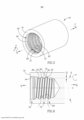
[0020] Para uma melhor compreensão do presente pedido e para mostrar como o mesmo pode ser realizado na prática, será feita referência agora aos desenhos anexos, nos quais: a Figura 1 é uma vista em corte transversal longitudinal em perspectiva de uma ferramenta de corte rotativa; a Figura 2 é uma vista em corte transversal longitudinal em perspectiva explodida da ferramenta de corte rotativa mostrada na Figura 1; a Figura 3 é uma vista lateral de uma cabeça de corte substituível mostrada nas Figuras 1 e 2; a Figura 4 é um detalhe da Figura 3; a Figura 5 é uma vista em perspectiva de um suporte para ferramenta mostrado nas Figuras 1 e 2; a Figura 6 é uma vista em corte transversal longitudinal de um membro de acoplamento fêmea mostrado na Figura 5; a Figura 7 é um detalhe da vista em corte transversal longitudinal da ferramenta de corte rotativa mostrada na Figura 1, quando a ferramenta de corte rotativa está em uma posição travada; a Figura 8 é uma vista esquemática da forma de rosca interna de uma rosca interna cônica com a forma de rosca interna de uma rosca interna reta e a forma de rosca externa de uma rosca externa reta sobreposta à mesma; e a Figura 9 são quatro diagramas que mostram a distribuição da força de contato sobre roscas externas retas, engatadas de modo rosqueado a roscas internas cônica e reta, respectivamente, quando a ferramenta de corte rotativa está montada e em funcionamento.[0020] For a better understanding of the present application and to show how it can be carried out in practice, reference will now be made to the accompanying drawings, in which: Figure 1 is a longitudinal cross-sectional view in perspective of a cutting tool rotary; Figure 2 is an exploded perspective longitudinal cross-sectional view of the rotary cutting tool shown in Figure 1; Figure 3 is a side view of the replaceable cutting head shown in Figures 1 and 2; Figure 4 is a detail of Figure 3; Figure 5 is a perspective view of a tool holder shown in Figures 1 and 2; Figure 6 is a longitudinal cross-sectional view of a female coupling member shown in Figure 5; Figure 7 is a detail longitudinal cross-sectional view of the rotary cutting tool shown in Figure 1 when the rotary cutting tool is in a locked position; Figure 8 is a schematic view of the internal thread form of a tapered internal thread with the internal thread form of a straight internal thread and the external thread form of a straight external thread superimposed thereon; and Figure 9 are four diagrams showing the distribution of contact force on straight external threads threadedly engaged with tapered and straight internal threads, respectively, when the rotary cutting tool is mounted and in operation.
[0021] Será reconhecido que, para simplicidade e clareza de ilustração, os elementos mostrados nas figuras não foram necessariamente desenhados em escala. Por exemplo, as dimensões de alguns dos elementos podem ser exageradas em relação a outros elementos para maior clareza, ou vários componentes físicos podem ser incluídos em um bloco ou elemento funcional. Quando considerado apropriado, os números de referência podem ser repetidos entre as figuras para indicar elementos correspondentes ou análogos.[0021] It will be recognized that, for simplicity and clarity of illustration, the elements shown in the figures have not necessarily been drawn to scale. For example, the dimensions of some of the elements can be exaggerated relative to other elements for clarity, or multiple physical components can be included in a functional block or element. Where deemed appropriate, reference numerals may be repeated between figures to indicate corresponding or analogous elements.
[0022] Na descrição a seguir, vários aspectos da matéria do presente pedido serão descritos. Para fins de explicação, configurações e detalhes específicos são estabelecidos com detalhes suficientes para prover uma compreensão completa da matéria do presente pedido. No entanto, será também evidente para um versado na técnica que a matéria do presente pedido pode ser praticada sem as configurações específicas e detalhes aqui apresentados.[0022] In the following description, various aspects of the subject matter of this application will be described. For purposes of explanation, specific settings and details are set forth in sufficient detail to provide a complete understanding of the subject matter of the present application. However, it will also be apparent to one skilled in the art that the subject matter of the present application can be practiced without the specific configurations and details presented herein.
[0023] A atenção é primeiramente dada às Figuras 1 e 2 mostrando uma ferramenta de corte rotativa 20 do tipo usado para operações de fresagem, especificamente fresagem lateral rápida, de acordo com formas de realização da matéria do presente pedido. A ferramenta de corte rotativa 20 tem um eixo geométrico longitudinal da ferramenta L em torno do qual a ferramenta rota na direção de rotação R.[0023] Attention is first drawn to Figures 1 and 2 showing a
[0024] A ferramenta de corte rotativa 20 inclui uma cabeça de corte substituível 22 que tem um eixo geométrico longitudinal de cabeça A, em torno do qual a cabeça de corte substituível 22 rota na direção de rotação R. O eixo geométrico longitudinal de cabeça A se estende na direção dianteira DF para a traseira DR. A cabeça de corte substituível 22 pode ser tipicamente feita de carboneto cementado.[0024] The
[0025] A ferramenta de corte rotativa 20 também inclui um suporte para ferramenta 24 tendo um eixo geométrico longitudinal de suporte C. O suporte para ferramenta 24 pode ser tipicamente feito de aço. A cabeça de corte substituível 22 pode ser retida de modo removível no suporte para ferramenta 24 por meio de um mecanismo de acoplamento rosqueado. Tal mecanismo de acoplamento rosqueado poderia possivelmente ser vantajoso para outros tipos de operações de corte rotativo diferentes do mencionado acima, tal como, por exemplo, alargamento ou perfuração.[0025] The
[0026] Deve ser reconhecido que o uso dos termos “dianteira” e “traseira” ao longo da descrição e das reivindicações refere-se a uma posição relativa da cabeça de corte substituível 22 ao suporte para ferramenta 24 da ferramenta de corte rotativa montada 20, como mostrado na Figura 1. Os termos “dianteira” e “traseira” podem também ser aplicados em uma direção do eixo geométrico longitudinal de cabeça A no sentido à esquerda e à direita, respectivamente, nas Figuras 3 e 4, e também em uma direção do eixo geométrico longitudinal de suporte C no sentido à esquerda e à direita, respectivamente, nas Figuras 5 e 6.[0026] It should be recognized that the use of the terms "front" and "rear" throughout the description and claims refers to a relative position of the
[0027] Referência é feita agora às Figuras 3 e 4. A cabeça de corte substituível 22 tem uma porção dianteira que forma uma porção de corte 26 e uma porção traseira que forma uma porção de montagem 28. De acordo com algumas formas de realização da matéria do presente pedido, a cabeça de corte substituível 22 pode ser formada a partir de uma construção de uma peça integral unitária. Isto provê uma vantagem à medida em que a cabeça de corte substituível 22 não tem inserções de corte destacáveis (não mostradas).[0027] Reference is now made to Figures 3 and 4. The
[0028] Em referência à Figura 3, a porção de corte 26 inclui pelo menos uma aresta de corte periférica 30. Neste exemplo não limitativo mostrado nos desenhos pode haver exatamente duas arestas de corte periféricas. Cada aresta de corte periférica 30 é formada na interseção de uma superfície de relevo periférico 32 e uma superfície de declive periférico 34. A superfície de relevo periférico 32 está localizada rotativamente atrás da aresta de corte periférica 30 e a superfície de declive periférico 34 está localizada rotativamente à frente da aresta de corte periférica 30, ambas em relação à direção de rotação R. A orientação da aresta de corte periférica 30 permite que sejam realizadas operações de corte de metal.[0028] Referring to Figure 3, the
[0029] De acordo com algumas formas de realização da matéria do presente pedido, a porção de corte 26 pode incluir pelo menos uma estria 36 para evacuar as aparas (não mostradas) que são produzidas durante a operação de corte. Uma estria 36 está associada a cada aresta de corte periférica 30. A cabeça de corte substituível 22 pode incluir uma ou mais arestas de corte de extremidade 30b em uma face de extremidade 37 da porção de corte 26. Neste exemplo não limitativo mostrado nos desenhos, a cabeça de corte substituível 22 pode incluir exatamente duas arestas de corte de extremidade 30b. Cada uma das duas arestas de corte de extremidade 30b pode ter uma aresta de corte lateral associada 30a.[0029] According to some embodiments of the matter of the present application, the
[0030] Em referência agora às Figuras 3 e 4, a porção de montagem 28 inclui um membro de acoplamento macho 38 que se projeta para a traseira a partir de uma superfície da base de cabeça 40. A superfície da base de cabeça 40 se estende transversalmente em relação ao eixo geométrico longitudinal de cabeça A e define um contorno entre a porção de corte 26 e porção de montagem 28. Isto é, a porção de corte 26 é formada na dianteira da superfície da base de cabeça 40 e a porção de montagem 28 é formada na traseira da superfície da base de cabeça 40. De acordo com algumas formas de realização da matéria do presente pedido, o membro de acoplamento macho 38 pode ser rígido. A superfície da base de cabeça 40 pode ser perpendicular ao eixo geométrico longitudinal de cabeça A. A superfície da base de cabeça 40 destina-se a encostar uma superfície correspondente no suporte para ferramenta 24 quando a ferramenta de corte rotativa 20 está em uma posição travada, como será descrito a seguir.[0030] Referring now to Figures 3 and 4, the
[0031] O membro de acoplamento macho 38 inclui uma rosca externa 42. No que se refere à Figura 4, a rosca externa 42 inclui um cume de rosca externa 44 que se estende de modo helicoidal em torno de um eixo geométrico de rosca externa B. O eixo geométrico de rosca externa B é coincidente com o eixo geométrico longitudinal da cabeça A. Desse modo, a porção de rosca externa 42 e a cabeça de corte substituível 22 são coaxiais. O cume de rosca externa 44 inclui superfícies de flanco externas dianteira e traseira 46, 48 e uma superfície de topo externa 50 que se estende entre as mesmas. As superfícies de flanco externas dianteira e traseira 46, 48 estão voltadas para direções axiais opostas DF, DR, com a superfície de flanco externa dianteira 46 voltada para a direção dianteira DF e a superfície de flanco externa traseira 48 voltada para a direção traseira DR. As superfícies de flanco externas dianteira e traseira 46, 48 delimitam uma ranhura de rosca externa 52. A ranhura de rosca externa 52 se estende de modo helicoidal em torno do eixo geométrico de rosca externa B e inclui uma superfície de fundo externa 54.[0031] The
[0032] Em uma vista em corte transversal tomada em um plano axial (isto é, um plano que contém o eixo geométrico de rosca externa B), a superfície de topo externa 50 forma uma pluralidade de cristas de rosca externa 56 e a superfície de fundo externa 54 forma uma pluralidade de raízes de roscas externas 58. De acordo com algumas formas de realização da matéria do presente pedido, a pluralidade de cristas de rosca externa 56 pode ser paralela ao eixo geométrico de rosca externa B e colinear entre si. A pluralidade de raízes de rosca externa 58 pode ser paralela ao eixo geométrico de rosca externa B e colinear entre si.[0032] In a cross-sectional view taken in an axial plane (i.e., a plane that contains the external thread axis B), the external
[0033] Em uma vista em corte transversal tomada em um plano axial contendo o eixo geométrico de rosca externa B, as superfícies de flanco externas dianteira e traseira 46, 48 podem ser inclinadas em um ângulo α de flanco externo em relação a um plano radial perpendicular ao eixo geométrico de rosca externa B. Preferencialmente, o ângulo α de flanco externo pode ser em torno de 17°. A rosca externa 42 define uma forma de rosca externa 60 que pode ser trapezoidal. A superfície de topo externa 50 e a superfície de fundo externa 54 podem transicionar suavemente para as superfícies de flanco externas dianteira e traseira 46, 48, respectivamente, definindo um raio. Em alternativa, a forma de rosca externa 60 pode ser triangular.[0033] In a cross-sectional view taken in an axial plane containing the external thread axis B, the front and rear external flank surfaces 46, 48 can be inclined at an external flank angle α with respect to a radial plane perpendicular to the external thread axis B. Preferably, the external flank angle α can be around 17°.
[0034] A superfície de topo externa 50 e a superfície de fundo externa 54 podem formar uma aresta. A pluralidade de cristas de rosca externa 56 define o diâmetro maior e a pluralidade de raízes de roscas externas 58 define o diâmetro menor da rosca externa 42, respectivamente. O diâmetro maior menos o diâmetro menor, dividido por dois, é igual à altura de rosca externa HE da rosca externa 42. A altura de rosca externa HE pode ser constante. De acordo com algumas formas de realização da matéria do presente pedido, a rosca externa 42 pode ter aproximadamente três voltas.[0034] The outer
[0035] A rosca externa 42 é uma rosca reta. Deverá ser reconhecido que o termo “rosca reta” ao longo da descrição e das reivindicações se refere a uma rosca em que o cume da rosca se estende em torno de um cilindro e, desse modo, as cristas da rosca são equidistantes do eixo geométrico da rosca. Do mesmo modo, deve ser reconhecido que o termo “rosca afilada” ao longo da descrição e reivindicações se refere a uma rosca em que o cume da rosca se estende em torno de um cone, cuja superfície se afila radialmente para dentro no sentido do eixo geométrico da rosca na direção traseira e diminui e, desse modo, as cristas da rosca diminuem em distância a partir do eixo geométrico da rosca na direção traseira.[0035] The
[0036] Como mostrado nas Figuras 3 e 4, o membro de acoplamento macho 38 inclui uma porção de mancal dianteira 62. A porção de mancal dianteira 50 está localizada no lado dianteiro da rosca externa 42. A porção de mancal dianteira 62 inclui uma superfície de encosto de cabeça dianteira 64 que se afila radialmente para dentro no sentido do eixo geométrico longitudinal de cabeça A em uma direção traseira DR. Isto é, a superfície de encosto de cabeça dianteira 64 tem um formato cônico voltado radialmente para fora. Nota-se que a superfície de encosto de cabeça dianteira 64 se destina a encostar uma superfície correspondente no suporte para ferramenta 24 quando a ferramenta de corte rotativa 20 está em uma posição travada, como será descrito a seguir.[0036] As shown in Figures 3 and 4, the
[0037] Deverá ser reconhecido que o uso dos termos “radialmente para dentro/para dentro” e “radialmente para fora/para fora” ao longo da descrição e reivindicações se refere a uma posição relativa em uma direção perpendicular em relação ao eixo geométrico longitudinal de cabeça A e/ou eixo geométrico longitudinal de suporte C, no sentido do e afastado do respectivo eixo geométrico, nas Figuras 3 a 4 e Figura 6.[0037] It should be recognized that the use of the terms “radially in/in” and “radially out/out” throughout the description and claims refers to a relative position in a perpendicular direction in relation to the longitudinal axis of head A and/or longitudinal axis of support C, towards and away from the respective geometric axis, in Figures 3 to 4 and Figure 6.
[0038] Em referência agora às Figuras 5 e 6, o suporte para ferramenta 24 tem um eixo geométrico longitudinal de suporte C que se estende na direção dianteira DF para a traseira DR. O suporte para ferramenta 24 inclui um membro de acoplamento fêmea 68 que se estende para a traseira a partir de uma superfície dianteira de suporte 70. A superfície dianteira de suporte 70 se estende transversalmente em relação ao eixo geométrico longitudinal C. De acordo com algumas formas de realização da matéria do presente pedido, a superfície dianteira de suporte 70 pode ser perpendicular ao eixo geométrico longitudinal de suporte C.[0038] Referring now to Figures 5 and 6, the
[0039] O membro de acoplamento fêmea 68 inclui uma rosca interna 72. Como mostrado em uma vista em corte transversal longitudinal do membro de acoplamento fêmea 68 contendo o eixo geométrico de rosca interna D (isto é, Figura 6), a rosca interna 72 inclui um cume de rosca interna 74 que se estende de modo helicoidal em torno de um eixo geométrico de rosca interna D. O eixo geométrico de rosca interna D é coincidente com o eixo geométrico longitudinal de suporte C. Desse modo, a porção de rosca interna 72 é coaxial com o suporte para ferramenta 24. O cume de rosca interna 74 inclui superfícies de flanco internas dianteira e traseira 76, 78 e uma superfície de topo interna 80 que se estende entre as mesmas. As superfícies de flanco internas dianteira e traseira 76, 78 estão voltadas para direções axiais opostas DF, DR, com a superfície de flanco interna dianteira 76 voltada para a direção dianteira DF e a superfície de flanco interna traseira 78 voltada para a direção traseira DR. As superfícies de flanco internas dianteira e traseira 76, 78 delimitam uma ranhura de rosca interna 82.[0039] The
[0040] A ranhura de rosca interna 82 se estende de modo helicoidal em torno do eixo geométrico de rosca interna D e inclui uma superfície de fundo interna 84. Em uma vista em corte transversal tomada em um plano axial (isto é, um plano que contém o eixo geométrico de rosca interna D) a superfície de topo interna 80 forma uma pluralidade de cristas de rosca interna 88 e a superfície de fundo interna 84 forma uma pluralidade de raízes de rosca internas 90. De acordo com algumas formas de realização da matéria do presente pedido, a pluralidade de cristas de rosca interna 88 pode ser paralela ao eixo geométrico de rosca interna D e colinear entre si. A pluralidade de raízes de rosca interna 90 pode ser paralela ao eixo geométrico de rosca interna D e seguir um padrão de distância que diminui a partir das mesmas na direção traseira DR.[0040] The
[0041] Em uma vista em corte transversal tomada em um plano axial contendo o eixo geométrico de rosca interna (D), as superfícies de flanco internas dianteira e traseira 76, 78 podem ser inclinadas em um ângulo β de flanco interno em relação a um plano radial perpendicular ao eixo geométrico de rosca interna D. De um modo preferido, o ângulo β de flanco interno pode ser de cerca de 17°. A rosca interna 72 define uma forma de rosca interna 86 que pode ser trapezoidal. No que se refere agora à Figura 8, os lados do trapézio podem não ser iguais em comprimento. A superfície de topo interna 80 e a superfície de fundo interna 84 podem transicionar suavemente para as superfícies de flanco internas dianteira e traseira 76, 78, respectivamente, definindo um raio. Em alternativa, a forma de rosca interna 86 pode ser triangular.[0041] In a cross-sectional view taken in an axial plane containing the internal thread axis (D), the front and rear internal flank surfaces 76, 78 can be inclined at an internal flank angle β with respect to a radial plane perpendicular to the internal thread axis D. Preferably, the internal flank angle β can be about 17°.
[0042] A superfície de topo interna 80 e a superfície de fundo interna 84 podem formar uma aresta. A pluralidade de cristas de rosca interna 88 define o diâmetro menor e a pluralidade de raízes de rosca internas 90 define o diâmetro maior da rosca interna 72, respectivamente. O diâmetro maior, menos o diâmetro menor, dividido por dois, é igual à altura da rosca interna HI da rosca interna 72. A altura interna da rosca HI pode ser constante, ou aumentar ou diminuir na direção traseira DR, dependendo de qual dos cumes de rosca interna 74 e ranhuras de rosca interna 82 se estende em torno de um respectivo cone K. Neste exemplo não limitativo mostrado nos desenhos, a altura da rosca interna HI diminui na direção traseira. De acordo com algumas formas de realização da matéria do presente pedido, a rosca interna 72 pode ter aproximadamente três voltas.[0042] The inner
[0043] A rosca interna 72 é uma rosca cônica. Deve ser reconhecido que o termo “rosca cônica” ao longo da descrição e das reivindicações refere- se a uma rosca em que pelo menos um dentre o cume de rosca e a ranhura de rosca se estende em torno de um cone respectivo, cuja superfície se afila radialmente para dentro no sentido do eixo geométrico da rosca na direção traseira e, desse modo, pelo menos uma das cristas de rosca e raízes de rosca diminuem em distância a partir do eixo geométrico de rosca na direção traseira. Tal rosca cônica pode ser formada rosqueando-se a extremidade dianteira oca de uma haste de aço cilíndrica com uma inserção de volta interna. Conforme a haste de aço rota e se move na direção axial para formar a rosca interna, ela também se move radialmente se afastando da inserção de corte “estática”, de modo que a rosca tenha uma configuração cônica. O cone e a rosca são coaxiais. Neste exemplo não limitativo mostrado na Figura 8, o cone é definido pelos pontos em que a superfície de fundo interna 84 transiciona para a superfície de flanco interna traseira 78.[0043]
[0044] De acordo com algumas formas de realização da matéria do presente pedido, pelo menos um dentre o cume de rosca interna 74 e a ranhura de rosca interna 82 pode se estender em torno de um cone K respectivo tendo um ângulo de cone y. O ângulo do cone Y pode estar na faixa de 0,02° < < 1,6°. Vantajosamente, o ângulo de cone y pode ser igual a exatamente 0,8°. Apenas a ranhura de rosca interna 82 pode se estender em torno de um respectivo cone K. Além disso, o cume de rosca interna 74 pode se estender em torno de um cilindro Y. Deve ser ainda reconhecido que o uso do termo “ângulo de cone” ao longo da descrição se refere a um ângulo formado pelas superfícies cônicas de um cone, em uma seção transversal longitudinal. Nota- se que o termo “seção transversal longitudinal” refere-se a uma seção transversal tomada em um plano contendo o eixo geométrico longitudinal. Tal seção transversal longitudinal resulta em um plano axial contendo o eixo geométrico longitudinal.[0044] According to some embodiments of the subject matter of the present application, at least one of the
[0045] Como mostrado nas Figuras 5 e 6, o membro de acoplamento fêmea 68 inclui uma porção de suporte dianteira 92. A porção de suporte dianteira 80 está localizada no lado dianteiro da rosca interna 72. A porção de suporte dianteira 92 inclui uma superfície de encosto de suporte dianteira 94 que se afila radialmente para dentro no sentido do eixo geométrico longitudinal de suporte C na direção traseira DR. Isto é, a superfície de encosto de suporte de suporte dianteiro 94 tem um formato cônico voltado radialmente para dentro.[0045] As shown in Figures 5 and 6, the
[0046] A montagem da ferramenta de corte rotativa 20 é conhecida, por exemplo, do documento n° U.S. 6.485.220 B2, que é aqui incorporado a título de referência na sua totalidade. Deve ser notado que a ferramenta de corte rotativa 20 é ajustável entre uma posição liberada e uma posição travada (ou montada).[0046] The assembly of the
[0047] Na posição liberada do membro de acoplamento macho 38 está localizado do lado de fora do membro de acoplamento fêmea 68.[0047] In the released position the
[0048] Na posição travada, o membro de acoplamento macho 38 está retido de modo removível no membro de acoplamento fêmea 68. Além disso, as roscas externas e internas 42, 72 engatam de modo rosqueado uma à outra. No que se refere agora a Figura 7, a superfície de encosto de cabeça dianteira 64 encosta a superfície de encosto de suporte dianteira 94. De acordo com algumas formas de realização da matéria do presente pedido, a superfície da base de cabeça voltada para a traseira 40 pode encostar na superfície dianteira de suporte voltado para a dianteira 70. A superfície de flanco interna traseira 78 pode encostar na superfície de flanco externa dianteira 46. A superfície de flanco interna dianteira 76 pode estar afastada da superfície de flanco externa traseira 48. A superfície de topo interna 80 pode estar afastada da superfície de fundo externa 54. A superfície de fundo interna 84 pode estar afastada da superfície de topo externa 50.[0048] In the locked position, the
[0049] A atenção agora é dada à Figura 8 mostrando uma vista esquemática da forma de rosca interna 86 de uma rosca interna cônica 72. Por meio de linhas tracejadas, uma forma de rosca interna imaginária 96 de uma rosca interna reta e uma forma de rosca externa imaginária 98 de uma rosca externa reta, que estão engatadas de modo rosqueado uma à outra, são sobrepostas. Nota-se que o ângulo de cone Y da rosca interna 72 que forma a forma de rosca interna 86 está exagerado para mostrar claramente as formas de rosca interna 86, 96 em relação uma à outra e, desse modo, as distâncias não representam valores verdadeiros.[0049] Attention is now given to Figure 8 showing a schematic view of the
[0050] Cada volta da forma de rosca interna 86 é deslocada do eixo geométrico de rosca D por uma distância que, em virtude da rosca interna 72 ser cônica, diminui à medida que a rosca interna 72 se estende de modo helicoidal em torno do eixo geométrico de rosca na direção traseira DR. Desse modo, cada porção de cume da forma de rosca interna 86 se estende além (ou posto de outra forma, tem uma parte “saliente”) de uma porção de cume correspondente da forma de rosca interna imaginária 96 tal que cada superfície de flanco interna traseira 78 é distanciada da respectiva superfície de flanco interna traseira imaginário 100 por uma distância de flanco E. Além disso, a distância do flanco E aumenta em magnitude na direção traseira DR. Ou seja, a distância do flanco E aumenta em magnitude para sucessivas voltas de rosca na direção traseira DR. De modo semelhante, cada porção de cume da forma de rosca interna 86 se estende para cobrir parcialmente (isto é, justapor) uma porção de cume correspondente da forma de rosca externa imaginária 98 de tal modo que cada superfície de flanco interna traseira 78 é distanciada da respectiva superfície de flanco externa dianteira imaginário 102 pela mesma distância de flanco E. Desse modo, claramente, quando montado (isto é, engatado de modo rosqueado), o engate friccional entre a rosca externa 42 e a rosca interna 72 aumenta em uma direção a partir da volta mais à frente da rosca externa 42 no sentido da volta mais para trás.[0050] Each turn of the
[0051] Referência é agora feita à Figura 9, mostrando quatro diagramas que mostram a distribuição de força de contato exercida sobre roscas externas retas que são engatadas de modo rosqueado com roscas internas reta e cônica, respectivamente, quando a ferramenta de corte rotativa está montada e em funcionamento. Os comprimentos das setas representam a magnitude das forças de contato. Pode ser visto que a distribuição das forças de contato, quando as ferramentas de corte rotativas 20 estão montadas e funcionando, em uma rosca externa reta engatada de modo rosqueado acoplada com uma rosca interna cônica (os dois diagramas à direita), estão localizados ainda na direção traseira DR comparada com uma rosca interna reta engatada de modo rosqueado com uma rosca interna reta (os dois diagramas à esquerda). Em particular, pode ser visto que quando a ferramenta de corte rotativa 20 que tem a rosca interna cônica é montada, quase não existem forças de contato localizadas em uma área dianteira A1 da rosca externa reta. Além disso, quando a dita ferramenta de corte rotativa 20 está em funcionamento, existem forças de contato em uma área posterior A2 da rosca externa reta. Em virtude do engate rosqueado anterior, a ferramenta de corte rotativa 20 tem uma estabilidade melhorada contra forças de corte laterais.[0051] Reference is now made to Figure 9, showing four diagrams showing the distribution of contact force exerted on straight external threads that are threadedly engaged with straight and tapered internal threads, respectively, when the rotary cutting tool is mounted and in operation. The lengths of the arrows represent the magnitude of the contact forces. It can be seen that the distribution of contact forces, when the
[0052] Embora a matéria do presente pedido tenha sido descrita com um certo grau de particularidade, deve ser entendido que várias alterações e modificações podem ser feitas sem se afastar do espírito ou escopo da invenção como reivindicado a seguir.[0052] While the subject matter of the present application has been described with a certain degree of particularity, it is to be understood that various changes and modifications may be made without departing from the spirit or scope of the invention as claimed below.
Claims (15)
Applications Claiming Priority (3)
| Application Number | Priority Date | Filing Date | Title |
|---|---|---|---|
| US15/075,782 | 2016-03-21 | ||
| US15/075,782 US10105771B2 (en) | 2016-03-21 | 2016-03-21 | Rotary cutting tool having tool holder with conical internal thread and replaceable cutting head with straight external thread, and said tool holder |
| PCT/IL2017/050259 WO2017163231A1 (en) | 2016-03-21 | 2017-03-01 | Rotary cutting tool having tool holder with conical internal thread and replaceable cutting head with straight external thread, and said tool holder |
Publications (2)
| Publication Number | Publication Date |
|---|---|
| BR112018067578A2 BR112018067578A2 (en) | 2019-01-08 |
| BR112018067578B1 true BR112018067578B1 (en) | 2023-02-28 |
Family
ID=58398232
Family Applications (1)
| Application Number | Title | Priority Date | Filing Date |
|---|---|---|---|
| BR112018067578-4A BR112018067578B1 (en) | 2016-03-21 | 2017-03-01 | ROTARY CUTTING TOOL AND TOOL HOLDER |
Country Status (11)
| Country | Link |
|---|---|
| US (1) | US10105771B2 (en) |
| EP (1) | EP3433042A1 (en) |
| JP (1) | JP7154131B2 (en) |
| KR (1) | KR102264414B1 (en) |
| CN (1) | CN108778590B (en) |
| BR (1) | BR112018067578B1 (en) |
| CA (1) | CA3016387A1 (en) |
| IL (1) | IL260857B (en) |
| RU (1) | RU2726050C2 (en) |
| TW (1) | TWI714720B (en) |
| WO (1) | WO2017163231A1 (en) |
Families Citing this family (8)
| Publication number | Priority date | Publication date | Assignee | Title |
|---|---|---|---|---|
| US20180154460A1 (en) * | 2015-06-12 | 2018-06-07 | Mitsubishi Materials Corporation | Tapered end mill and cutting head |
| US10335871B2 (en) * | 2016-04-12 | 2019-07-02 | Iscar, Ltd. | Replaceable face-milling head with integrally formed threaded shank-connector |
| DE102017127814A1 (en) * | 2017-11-24 | 2019-05-29 | Hartmetall-Werkzeugfabrik Paul Horn Gmbh | Tool for machining a workpiece |
| CN109434143B (en) * | 2018-09-26 | 2020-03-10 | 厦门金鹭特种合金有限公司 | Head exchange type cutting tool |
| US11059109B2 (en) * | 2018-12-31 | 2021-07-13 | Iscar, Ltd. | Cutting head having torque transmission surfaces on a mounting protuberance and rotary cutting tool having such cutting head |
| US11446746B2 (en) | 2019-12-10 | 2022-09-20 | Iscar, Ltd. | Replaceable cutting head having back-tapered conical external thread and rotary cutting tool |
| US11376676B2 (en) | 2020-07-07 | 2022-07-05 | Iscar, Ltd. | Rotary cutting head having cutting edges extending past key actuating portion |
| US11426803B2 (en) | 2020-09-08 | 2022-08-30 | Iscar, Ltd. | Replaceable cutting head having external thread with concavely curved root and rotary cutting tool |
Family Cites Families (39)
| Publication number | Priority date | Publication date | Assignee | Title |
|---|---|---|---|---|
| SU121327A1 (en) * | 1959-02-02 | 1959-11-30 | К.М. Романов | The method of mounting tail cutters and other similar tools installed in the boring bar cone, for example, a horizontal boring machine |
| US3762745A (en) * | 1972-04-03 | 1973-10-02 | Hughes Tool Co | Connection members with high torque carrying capacity |
| FR2359353A1 (en) * | 1976-07-23 | 1978-02-17 | Vallourec | SEAL FOR TUBES, ESPECIALLY FOR OIL TUBES |
| SU1349887A1 (en) * | 1985-05-22 | 1987-11-07 | Московский станкостроительный завод "Красный пролетарий" им.А.И.Ефремова | Composite cutting tool |
| JPS6252387U (en) * | 1985-09-20 | 1987-04-01 | ||
| JPH0686916B2 (en) * | 1988-11-01 | 1994-11-02 | エスエムシー株式会社 | Pipe fitting |
| RU1807755C (en) * | 1990-01-15 | 1995-01-09 | Сосульников Игорь Леонидович | Threaded joint |
| JPH0648075B2 (en) * | 1990-04-16 | 1994-06-22 | エスエムシー株式会社 | Pipe fitting |
| US5114286A (en) | 1991-08-13 | 1992-05-19 | Calkins Donald W | Interchangeable tool alignment system |
| JPH09152069A (en) * | 1995-11-28 | 1997-06-10 | Yoshitoshi:Kk | Mechanical joint |
| US5695297A (en) * | 1996-09-11 | 1997-12-09 | Fenner, Inc. | Mounting device |
| IL136032A (en) * | 2000-05-09 | 2003-12-10 | Iscar Ltd | Tool joint |
| US7431543B2 (en) * | 2002-02-15 | 2008-10-07 | Dihart Ag | Machine reamer |
| IL150013A (en) * | 2002-06-04 | 2007-06-17 | Gil Hecht | Rotary cutting tool |
| SE528299C2 (en) * | 2004-09-24 | 2006-10-17 | Seco Tools Ab | Cutting tip and cutting tool with holder part designed as truncated conical thread |
| CA2605431C (en) * | 2005-04-20 | 2015-06-30 | Erwin Tomm | Threaded connector with interlock |
| CN2780386Y (en) * | 2005-05-10 | 2006-05-17 | 王春良 | Internal external thread chuck |
| IL172121A0 (en) | 2005-11-22 | 2009-02-11 | Joseph Pano | Cutting tool assembly |
| SE530043C2 (en) * | 2006-04-20 | 2008-02-12 | Sandvik Intellectual Property | Tools for chip separating machining and part thereof |
| SE532394C2 (en) | 2007-06-04 | 2010-01-12 | Sandvik Intellectual Property | Tools for chip separating machining and basic body for this |
| SE531746C2 (en) * | 2007-07-03 | 2009-07-28 | Seco Tools Ab | In several parts tool unit and cutting tool designed |
| CN101844236B (en) * | 2009-03-27 | 2014-04-23 | 三菱综合材料株式会社 | Exchangeable cutting head and cutting tool having the same |
| JP5350149B2 (en) * | 2009-09-07 | 2013-11-27 | ダイジ▲ェ▼ット工業株式会社 | Cutting tools |
| US9810029B2 (en) * | 2011-01-26 | 2017-11-07 | Bly Ip Inc. | Drill string components resistant to jamming |
| US9802256B2 (en) * | 2012-02-07 | 2017-10-31 | Franz Haimer Maschinenbau Kg | Screw-in tool and tool holder for such a screw-in tool |
| DE102012100976B4 (en) * | 2012-02-07 | 2014-04-24 | Franz Haimer Maschinenbau Kg | Screwing tool and tool holder for such a screw-in |
| US9868162B2 (en) * | 2012-03-29 | 2018-01-16 | Hitachi Tool Engineering, Ltd. | Machining head, holder and exchangeable tip cutting tool |
| DE102012104606B4 (en) * | 2012-05-29 | 2015-11-19 | Franz Haimer Maschinenbau Kg | Tool holder for a screw-in tool |
| DE102012107546A1 (en) * | 2012-08-17 | 2014-02-20 | Franz Haimer Maschinenbau Kg | tooling |
| US20140056658A1 (en) * | 2012-08-24 | 2014-02-27 | Sumitomo Electric Hardmetal Corp. | Cutting tool with removable head |
| DE102013100939A1 (en) * | 2013-01-30 | 2014-07-31 | Franz Haimer Maschinenbau Kg | Tool holder for a screw-in tool |
| US9120164B2 (en) | 2013-04-29 | 2015-09-01 | Iscar, Ltd. | Cutting tool having a tool coupling with offset peripheral and central coupling threads and method of assembly thereof |
| US9643262B2 (en) * | 2013-07-25 | 2017-05-09 | Kennametal Inc. | Coupling mechanism for cutting tool |
| US9643264B2 (en) * | 2013-07-25 | 2017-05-09 | Kennametal Inc. | Coupling mechanism for cutting tool |
| CN204195344U (en) * | 2014-01-23 | 2015-03-11 | 上海新山田精密刀具有限公司 | For cutting tool and the rigidly connected handle of a knife of rotating shaft |
| CN203843263U (en) * | 2014-02-28 | 2014-09-24 | 贵州劲锋精密工具有限公司 | Tool clamping device |
| US9889509B2 (en) * | 2014-05-05 | 2018-02-13 | Kennametal Inc. | Cutter heads with improved coupling |
| DE112015002167T5 (en) * | 2014-05-08 | 2017-01-26 | Kennametal Inc. | Coupling mechanism for cutting tools |
| TWM517035U (en) * | 2015-04-10 | 2016-02-11 | 呂春明 | One piece hydrostatic lead screw nut |
-
2016
- 2016-03-21 US US15/075,782 patent/US10105771B2/en active Active
-
2017
- 2017-02-10 TW TW106104525A patent/TWI714720B/en active
- 2017-03-01 CN CN201780018830.9A patent/CN108778590B/en active Active
- 2017-03-01 CA CA3016387A patent/CA3016387A1/en active Pending
- 2017-03-01 EP EP17712853.5A patent/EP3433042A1/en active Pending
- 2017-03-01 KR KR1020187026635A patent/KR102264414B1/en active IP Right Grant
- 2017-03-01 RU RU2018136881A patent/RU2726050C2/en active
- 2017-03-01 WO PCT/IL2017/050259 patent/WO2017163231A1/en active Application Filing
- 2017-03-01 BR BR112018067578-4A patent/BR112018067578B1/en active IP Right Grant
- 2017-03-01 JP JP2018540098A patent/JP7154131B2/en active Active
-
2018
- 2018-07-30 IL IL260857A patent/IL260857B/en unknown
Also Published As
| Publication number | Publication date |
|---|---|
| CA3016387A1 (en) | 2017-09-28 |
| CN108778590A (en) | 2018-11-09 |
| KR102264414B1 (en) | 2021-06-16 |
| KR20180125476A (en) | 2018-11-23 |
| TWI714720B (en) | 2021-01-01 |
| RU2726050C2 (en) | 2020-07-08 |
| TW201733716A (en) | 2017-10-01 |
| RU2018136881A (en) | 2020-04-22 |
| RU2018136881A3 (en) | 2020-05-22 |
| WO2017163231A1 (en) | 2017-09-28 |
| US10105771B2 (en) | 2018-10-23 |
| US20170266738A1 (en) | 2017-09-21 |
| JP2019512401A (en) | 2019-05-16 |
| EP3433042A1 (en) | 2019-01-30 |
| BR112018067578A2 (en) | 2019-01-08 |
| JP7154131B2 (en) | 2022-10-17 |
| IL260857B (en) | 2022-02-01 |
| CN108778590B (en) | 2021-06-22 |
Similar Documents
| Publication | Publication Date | Title |
|---|---|---|
| BR112018067578B1 (en) | ROTARY CUTTING TOOL AND TOOL HOLDER | |
| KR102465176B1 (en) | Interchangeable cutting heads, tool holders and rotary cutting tools having a threaded mounting portion with two spaced apart conical adjacent surfaces provided with the same cone angle | |
| BR112015012866B1 (en) | replaceable cutting head, cutting tool and tool holder | |
| BRPI0720414B1 (en) | CUTTING INSERT AND CUTTING TOOL | |
| KR20130115167A (en) | Cutting head with coolant channel | |
| US20140348601A1 (en) | Cutting Insert Having A Rearwardly Offset Cutting Edge And Cutting Tool | |
| BRPI0618671A2 (en) | cutting tool and tool body | |
| BR112020010426B1 (en) | SPLITTING TOOL BODY, AND, ROTARY SLOT CUTTING TOOL | |
| BR112013012104B1 (en) | snipping tool | |
| KR20170135974A (en) | Tool coupling device for drills and reamers | |
| BR112019020042B1 (en) | REPLACEABLE CUTTING INSERT AND CUTTING TOOL | |
| US11446746B2 (en) | Replaceable cutting head having back-tapered conical external thread and rotary cutting tool | |
| US11426803B2 (en) | Replaceable cutting head having external thread with concavely curved root and rotary cutting tool |
Legal Events
| Date | Code | Title | Description |
|---|---|---|---|
| B06W | Patent application suspended after preliminary examination (for patents with searches from other patent authorities) chapter 6.23 patent gazette] | ||
| B350 | Update of information on the portal [chapter 15.35 patent gazette] | ||
| B06A | Patent application procedure suspended [chapter 6.1 patent gazette] | ||
| B09A | Decision: intention to grant [chapter 9.1 patent gazette] | ||
| B16A | Patent or certificate of addition of invention granted [chapter 16.1 patent gazette] |
Free format text: PRAZO DE VALIDADE: 20 (VINTE) ANOS CONTADOS A PARTIR DE 01/03/2017, OBSERVADAS AS CONDICOES LEGAIS |