BR112018008240B1 - FLUID CONTROL VALVE - Google Patents
FLUID CONTROL VALVE Download PDFInfo
- Publication number
- BR112018008240B1 BR112018008240B1 BR112018008240-6A BR112018008240A BR112018008240B1 BR 112018008240 B1 BR112018008240 B1 BR 112018008240B1 BR 112018008240 A BR112018008240 A BR 112018008240A BR 112018008240 B1 BR112018008240 B1 BR 112018008240B1
- Authority
- BR
- Brazil
- Prior art keywords
- port
- valve
- fluid
- pressure
- pressure chamber
- Prior art date
Links
Images


Classifications
-
- F—MECHANICAL ENGINEERING; LIGHTING; HEATING; WEAPONS; BLASTING
- F15—FLUID-PRESSURE ACTUATORS; HYDRAULICS OR PNEUMATICS IN GENERAL
- F15B—SYSTEMS ACTING BY MEANS OF FLUIDS IN GENERAL; FLUID-PRESSURE ACTUATORS, e.g. SERVOMOTORS; DETAILS OF FLUID-PRESSURE SYSTEMS, NOT OTHERWISE PROVIDED FOR
- F15B11/00—Servomotor systems without provision for follow-up action; Circuits therefor
- F15B11/02—Systems essentially incorporating special features for controlling the speed or actuating force of an output member
- F15B11/024—Systems essentially incorporating special features for controlling the speed or actuating force of an output member by means of differential connection of the servomotor lines, e.g. regenerative circuits
-
- F—MECHANICAL ENGINEERING; LIGHTING; HEATING; WEAPONS; BLASTING
- F15—FLUID-PRESSURE ACTUATORS; HYDRAULICS OR PNEUMATICS IN GENERAL
- F15B—SYSTEMS ACTING BY MEANS OF FLUIDS IN GENERAL; FLUID-PRESSURE ACTUATORS, e.g. SERVOMOTORS; DETAILS OF FLUID-PRESSURE SYSTEMS, NOT OTHERWISE PROVIDED FOR
- F15B11/00—Servomotor systems without provision for follow-up action; Circuits therefor
- F15B11/06—Servomotor systems without provision for follow-up action; Circuits therefor involving features specific to the use of a compressible medium, e.g. air, steam
- F15B11/064—Servomotor systems without provision for follow-up action; Circuits therefor involving features specific to the use of a compressible medium, e.g. air, steam with devices for saving the compressible medium
-
- F—MECHANICAL ENGINEERING; LIGHTING; HEATING; WEAPONS; BLASTING
- F15—FLUID-PRESSURE ACTUATORS; HYDRAULICS OR PNEUMATICS IN GENERAL
- F15B—SYSTEMS ACTING BY MEANS OF FLUIDS IN GENERAL; FLUID-PRESSURE ACTUATORS, e.g. SERVOMOTORS; DETAILS OF FLUID-PRESSURE SYSTEMS, NOT OTHERWISE PROVIDED FOR
- F15B13/00—Details of servomotor systems ; Valves for servomotor systems
- F15B13/02—Fluid distribution or supply devices characterised by their adaptation to the control of servomotors
- F15B13/04—Fluid distribution or supply devices characterised by their adaptation to the control of servomotors for use with a single servomotor
- F15B13/042—Fluid distribution or supply devices characterised by their adaptation to the control of servomotors for use with a single servomotor operated by fluid pressure
-
- F—MECHANICAL ENGINEERING; LIGHTING; HEATING; WEAPONS; BLASTING
- F15—FLUID-PRESSURE ACTUATORS; HYDRAULICS OR PNEUMATICS IN GENERAL
- F15B—SYSTEMS ACTING BY MEANS OF FLUIDS IN GENERAL; FLUID-PRESSURE ACTUATORS, e.g. SERVOMOTORS; DETAILS OF FLUID-PRESSURE SYSTEMS, NOT OTHERWISE PROVIDED FOR
- F15B15/00—Fluid-actuated devices for displacing a member from one position to another; Gearing associated therewith
- F15B15/08—Characterised by the construction of the motor unit
- F15B15/14—Characterised by the construction of the motor unit of the straight-cylinder type
- F15B15/149—Fluid interconnections, e.g. fluid connectors, passages
-
- F—MECHANICAL ENGINEERING; LIGHTING; HEATING; WEAPONS; BLASTING
- F15—FLUID-PRESSURE ACTUATORS; HYDRAULICS OR PNEUMATICS IN GENERAL
- F15B—SYSTEMS ACTING BY MEANS OF FLUIDS IN GENERAL; FLUID-PRESSURE ACTUATORS, e.g. SERVOMOTORS; DETAILS OF FLUID-PRESSURE SYSTEMS, NOT OTHERWISE PROVIDED FOR
- F15B21/00—Common features of fluid actuator systems; Fluid-pressure actuator systems or details thereof, not covered by any other group of this subclass
- F15B21/14—Energy-recuperation means
-
- F—MECHANICAL ENGINEERING; LIGHTING; HEATING; WEAPONS; BLASTING
- F16—ENGINEERING ELEMENTS AND UNITS; GENERAL MEASURES FOR PRODUCING AND MAINTAINING EFFECTIVE FUNCTIONING OF MACHINES OR INSTALLATIONS; THERMAL INSULATION IN GENERAL
- F16K—VALVES; TAPS; COCKS; ACTUATING-FLOATS; DEVICES FOR VENTING OR AERATING
- F16K11/00—Multiple-way valves, e.g. mixing valves; Pipe fittings incorporating such valves
- F16K11/02—Multiple-way valves, e.g. mixing valves; Pipe fittings incorporating such valves with all movable sealing faces moving as one unit
- F16K11/04—Multiple-way valves, e.g. mixing valves; Pipe fittings incorporating such valves with all movable sealing faces moving as one unit comprising only lift valves
- F16K11/044—Multiple-way valves, e.g. mixing valves; Pipe fittings incorporating such valves with all movable sealing faces moving as one unit comprising only lift valves with movable valve members positioned between valve seats
-
- F—MECHANICAL ENGINEERING; LIGHTING; HEATING; WEAPONS; BLASTING
- F16—ENGINEERING ELEMENTS AND UNITS; GENERAL MEASURES FOR PRODUCING AND MAINTAINING EFFECTIVE FUNCTIONING OF MACHINES OR INSTALLATIONS; THERMAL INSULATION IN GENERAL
- F16K—VALVES; TAPS; COCKS; ACTUATING-FLOATS; DEVICES FOR VENTING OR AERATING
- F16K15/00—Check valves
- F16K15/18—Check valves with actuating mechanism; Combined check valves and actuated valves
- F16K15/182—Check valves with actuating mechanism; Combined check valves and actuated valves with actuating mechanism
- F16K15/1825—Check valves with actuating mechanism; Combined check valves and actuated valves with actuating mechanism for check valves with flexible valve members
-
- F—MECHANICAL ENGINEERING; LIGHTING; HEATING; WEAPONS; BLASTING
- F16—ENGINEERING ELEMENTS AND UNITS; GENERAL MEASURES FOR PRODUCING AND MAINTAINING EFFECTIVE FUNCTIONING OF MACHINES OR INSTALLATIONS; THERMAL INSULATION IN GENERAL
- F16K—VALVES; TAPS; COCKS; ACTUATING-FLOATS; DEVICES FOR VENTING OR AERATING
- F16K31/00—Actuating devices; Operating means; Releasing devices
- F16K31/12—Actuating devices; Operating means; Releasing devices actuated by fluid
- F16K31/122—Actuating devices; Operating means; Releasing devices actuated by fluid the fluid acting on a piston
- F16K31/1221—Actuating devices; Operating means; Releasing devices actuated by fluid the fluid acting on a piston one side of the piston being spring-loaded
-
- F—MECHANICAL ENGINEERING; LIGHTING; HEATING; WEAPONS; BLASTING
- F16—ENGINEERING ELEMENTS AND UNITS; GENERAL MEASURES FOR PRODUCING AND MAINTAINING EFFECTIVE FUNCTIONING OF MACHINES OR INSTALLATIONS; THERMAL INSULATION IN GENERAL
- F16K—VALVES; TAPS; COCKS; ACTUATING-FLOATS; DEVICES FOR VENTING OR AERATING
- F16K31/00—Actuating devices; Operating means; Releasing devices
- F16K31/44—Mechanical actuating means
- F16K31/52—Mechanical actuating means with crank, eccentric, or cam
- F16K31/524—Mechanical actuating means with crank, eccentric, or cam with a cam
- F16K31/52408—Mechanical actuating means with crank, eccentric, or cam with a cam comprising a lift valve
- F16K31/52416—Mechanical actuating means with crank, eccentric, or cam with a cam comprising a lift valve comprising a multiple-way lift valve
-
- F—MECHANICAL ENGINEERING; LIGHTING; HEATING; WEAPONS; BLASTING
- F15—FLUID-PRESSURE ACTUATORS; HYDRAULICS OR PNEUMATICS IN GENERAL
- F15B—SYSTEMS ACTING BY MEANS OF FLUIDS IN GENERAL; FLUID-PRESSURE ACTUATORS, e.g. SERVOMOTORS; DETAILS OF FLUID-PRESSURE SYSTEMS, NOT OTHERWISE PROVIDED FOR
- F15B2211/00—Circuits for servomotor systems
- F15B2211/30—Directional control
- F15B2211/305—Directional control characterised by the type of valves
- F15B2211/3056—Assemblies of multiple valves
- F15B2211/30565—Assemblies of multiple valves having multiple valves for a single output member, e.g. for creating higher valve function by use of multiple valves like two 2/2-valves replacing a 5/3-valve
- F15B2211/3058—Assemblies of multiple valves having multiple valves for a single output member, e.g. for creating higher valve function by use of multiple valves like two 2/2-valves replacing a 5/3-valve having additional valves for interconnecting the fluid chambers of a double-acting actuator, e.g. for regeneration mode or for floating mode
-
- F—MECHANICAL ENGINEERING; LIGHTING; HEATING; WEAPONS; BLASTING
- F15—FLUID-PRESSURE ACTUATORS; HYDRAULICS OR PNEUMATICS IN GENERAL
- F15B—SYSTEMS ACTING BY MEANS OF FLUIDS IN GENERAL; FLUID-PRESSURE ACTUATORS, e.g. SERVOMOTORS; DETAILS OF FLUID-PRESSURE SYSTEMS, NOT OTHERWISE PROVIDED FOR
- F15B2211/00—Circuits for servomotor systems
- F15B2211/70—Output members, e.g. hydraulic motors or cylinders or control therefor
- F15B2211/705—Output members, e.g. hydraulic motors or cylinders or control therefor characterised by the type of output members or actuators
- F15B2211/7051—Linear output members
- F15B2211/7053—Double-acting output members
-
- F—MECHANICAL ENGINEERING; LIGHTING; HEATING; WEAPONS; BLASTING
- F15—FLUID-PRESSURE ACTUATORS; HYDRAULICS OR PNEUMATICS IN GENERAL
- F15B—SYSTEMS ACTING BY MEANS OF FLUIDS IN GENERAL; FLUID-PRESSURE ACTUATORS, e.g. SERVOMOTORS; DETAILS OF FLUID-PRESSURE SYSTEMS, NOT OTHERWISE PROVIDED FOR
- F15B2211/00—Circuits for servomotor systems
- F15B2211/80—Other types of control related to particular problems or conditions
- F15B2211/885—Control specific to the type of fluid, e.g. specific to magnetorheological fluid
- F15B2211/8855—Compressible fluids, e.g. specific to pneumatics
Abstract
VÁLVULA DE CONTROLE DE FLUIDO. [Objetivo] Fornecer uma válvula de controle de fluido que tem uma configuração adequada para a reutilização de ar de escape que é extraído de uma câmara de pressão de um atuador de pressão de fluido conectando-se a válvula de controle de fluido à câmara de pressão. [Solução] Uma válvula de controle de fluido inclui uma passagem de fornecimento de ar 14 que permite que uma primeira porta 11 e uma segunda porta 12 se comuniquem uma com a outra, uma passagem de ar de escape 15 que permite que a segunda porta 12 e uma terceira porta 13 se comuniquem uma com a outra, uma primeira válvula de retenção 20 fornecida à passagem de fornecimento de ar 15, uma segunda válvula de retenção 21 fornecida à passagem de ar de escape 15, um elemento de válvula 30 que abre e fecha uma passagem da segunda porta 12 para a terceira porta 13 e um orifício de válvula 22 através do qual o elemento de válvula 30 se estende de maneira a ser deslizável em uma direção axial do elemento de válvula 30. A passagem de ar de escape 15 é um vão 15b fornecido entre o orifício de válvula 22 e o elemento de válvula 30. O elemento de válvula 30 tem uma primeira (...).FLUID CONTROL VALVE. [Objective] To provide a fluid control valve that has a suitable configuration for the reuse of exhaust air that is drawn from a pressure chamber of a fluid pressure actuator by connecting the fluid control valve to the pressure chamber . [Solution] A fluid control valve includes an air supply passage 14 that allows a first port 11 and a second port 12 to communicate with each other, an exhaust air passage 15 that allows the second port 12 to and a third port 13 communicate with each other, a first check valve 20 provided to the air supply passage 15, a second check valve 21 provided to the exhaust air passage 15, a valve element 30 which opens and closes a passage from the second port 12 to the third port 13 and a valve port 22 through which the valve element 30 extends so as to be slidable in an axial direction of the valve element 30. The exhaust air passage 15 is a gap 15b provided between the valve port 22 and the valve element 30. The valve element 30 has a first (...).
Description
[001] A presente invenção refere-se a uma válvula de controle de fluido, por exemplo, uma válvula de controle de fluido a ser fornecida entre uma válvula de comutação conectada a uma fonte de pressão de fluido e um cilindro de ação dupla que inclui primeira e segunda câmaras de pressão.[001] The present invention relates to a fluid control valve, for example, a fluid control valve to be provided between a switching valve connected to a fluid pressure source and a double-acting cylinder that includes first and second pressure chambers.
[002] Em geral, um cilindro de pressão de fluido de ação dupla é conhecido, em que duas câmaras de pressão separadas uma da outra por um pistão têm respectivas portas de fornecimento/exaustão de ar, e as portas de fornecimento/exaustão de ar são alternadamente conectadas a uma fonte de pressão de fluido através, por exemplo, da comutação de uma válvula eletromagnética conectada à fonte de pressão de fluido, por meio da qual o pistão é movido para trás e para frente com uma pressão de fluido aplicada ao mesmo.[002] In general, a double-acting fluid pressure cylinder is known, in which two pressure chambers separated from each other by a piston have respective air supply/exhaust ports, and the air supply/exhaust ports are alternately connected to a source of fluid pressure by, for example, switching an electromagnetic valve connected to the source of fluid pressure, whereby the piston is moved back and forth with a fluid pressure applied thereto .
[003] Tipicamente, em tal cilindro de pressão de fluido de ação dupla, quando um pistão é movido para trás e para frente com a pressão de fluido aplicada ao mesmo, o fluido comprimido em uma das câmaras de pressão que está no lado de escape é descarregado para a atmosfera conforme a câmara de pressão se contrai com o movimento do pistão.[003] Typically, in such a double acting fluid pressure cylinder, when a piston is moved back and forth with fluid pressure applied thereto, the fluid compressed in one of the pressure chambers which is on the exhaust side is discharged to atmosphere as the pressure chamber contracts with piston movement.
[004] Do ponto de vista de economia de energia, o ar comprimido que é descarregado da câmara de pressão com o movimento de tal atuador de pressão de fluido é desejavelmente reutilizado tanto quanto possível.[004] From the point of view of energy saving, the compressed air that is discharged from the pressure chamber with the movement of such a fluid pressure actuator is desirably reused as much as possible.
[005] Consequentemente, um aparelho de cilindro pneumático é proposto por PTL 1 em que o ar de escape de uma câmara de pressão de lado de haste sofre refluxo em uma câmara de pressão de lado de cabeça e é reutilizado quando uma haste de um cilindro de dupla ação é movida para frente. Esse aparelho emprega, como uma válvula de comutação conectada a uma fonte de pressão pneumática, uma válvula de comutação de duas posições de quatro vias que tem uma função de fornecimento e exaustão de ar comprimido e do cilindro e uma função que ocasiona o refluxo do ar de escape.[005] Consequently, a pneumatic cylinder apparatus is proposed by PTL 1 in which the exhaust air from a rod-side pressure chamber is refluxed into a head-side pressure chamber and is reused when a rod of a cylinder of double action is moved forward. This apparatus employs, as a switchover valve connected to a pneumatic pressure source, a four-way two-position switchover valve that has a function for supplying and exhausting compressed and cylinder air and a function for causing the backflow of air. exhaust.
[006] LPT 1: Publicação de Pedido de Patente Japonesa Não Examinada no 8-42511[006] LPT 1: Japanese Unexamined Patent Application Publication No. 8-42511
[007] Um objetivo da presente invenção é fornecer uma válvula de controle de fluido que tem uma configuração adequada para a reutilização de ar de escape que é extraído de uma câmara de pressão de um atuador de pressão de fluido conectando-se a válvula de controle de fluido à câmara de pressão.[007] An object of the present invention is to provide a fluid control valve that has a suitable configuration for the reuse of exhaust air that is extracted from a pressure chamber of a fluid pressure actuator connecting the control valve of fluid to the pressure chamber.
[008] Para solucionar o problema acima, uma válvula de controle de fluido de acordo com a presente invenção deve ser fornecida entre uma válvula de comutação conectada a uma fonte de pressão de fluido e um cilindro de pressão de fluido de ação dupla que inclui uma primeira câmara de pressão fornecida em um lado de cabeça e uma segunda câmara de pressão fornecida em um lado de haste, em que quando o cilindro de pressão de fluido é ativado com uma comutação da válvula de comutação, o fluido comprimido que é descarregado da segunda câmara de pressão do cilindro de pressão de fluido sofre refluxo na primeira câmara de pressão. A válvula de controle de fluido inclui uma primeira porta a ser conectada à válvula de comutação, uma segunda porta a ser conectada à segunda câmara de pressão, uma terceira porta a ser conectada à primeira câmara de pressão, uma passagem de fornecimento de ar que permite que a primeira porta e a segunda porta se comuniquem, uma passagem de ar de escape que permite que a segunda porta e a terceira porta se comuniquem, uma primeira válvula de retenção fornecida à passagem de fornecimento de ar e que permite que o fluido comprimido flua de um lado da primeira porta para um lado da segunda porta enquanto que impede que o fluido comprimido flua do lado da segunda porta para o lado da primeira porta, uma segunda válvula de retenção fornecida à passagem de ar de escape e que permite que o fluido comprimido flua do lado da segunda porta para um lado da terceira porta enquanto que impede que o fluido comprimido flua do lado da terceira porta para o lado da segunda porta, um elemento de válvula que abre e fecha uma passagem da segunda porta para a terceira porta, e um orifício de válvula através do qual o elemento de válvula se estende de tal maneira a ser deslizável em uma direção axial do elemento de válvula. A passagem de ar de escape é um vão disposto entre o orifício de válvula e o elemento de válvula. O elemento de válvula tem uma primeira superfície de recebimento de pressão que causa uma pressão de fluido na primeira porta para agir em uma direção de fechamento do elemento de válvula, e uma segunda superfície de recebimento de pressão que causa uma pressão de fluido na segunda porta para agir em uma direção de abertura do elemento de válvula.[008] To solve the above problem, a fluid control valve according to the present invention must be provided between a switching valve connected to a source of fluid pressure and a double-acting fluid pressure cylinder that includes a first pressure chamber provided on a head side and a second pressure chamber provided on a rod side, wherein when the fluid pressure cylinder is activated with a switching of the switching valve, the compressed fluid that is discharged from the second pressure chamber of the fluid pressure cylinder undergoes reflux in the first pressure chamber. The fluid control valve includes a first port to be connected to the switching valve, a second port to be connected to the second pressure chamber, a third port to be connected to the first pressure chamber, an air supply passage that allows the first port and the second port to communicate, an exhaust air passage allowing the second port and the third port to communicate, a first check valve provided to the air supply passage and allowing the compressed fluid to flow from one side of the first port to one side of the second port while preventing compressed fluid from flowing from the second port side to the first port side, a second check valve provided to the exhaust air passage and allowing the fluid to compressed fluid from flowing from the second port side to one side of the third port while preventing compressed fluid from flowing from the third port side to the second port side, a valve element which opens and closes a passage from the second port to the third port, and a valve port through which the valve member extends in such a manner as to be slidable in an axial direction of the valve member. The exhaust air passage is a gap disposed between the valve orifice and the valve member. The valve element has a first pressure receiving surface that causes a fluid pressure in the first port to act in a closing direction of the valve element, and a second pressure receiving surface that causes a fluid pressure in the second port. to act in an opening direction of the valve element.
[009] Outra válvula de controle de fluido de acordo com a presente invenção inclui uma primeira porta, uma segunda porta e uma terceira porta através da qual o fluido comprimido flui; uma passagem de fornecimento de ar que permite que a primeira porta e a segunda porta se comuniquem; uma passagem de ar de escape que permite que a segunda porta e a terceira porta se comuniquem; uma primeira válvula de retenção fornecida à passagem de fornecimento de ar e que permite que o fluido comprimido flua de um lado da primeira porta para um lado da segunda porta enquanto que impede que o fluido comprimido flua do lado da segunda porta para o lado da primeira porta; uma segunda válvula de retenção fornecida à passagem de ar de escape e que permite que o fluido comprimido flua do lado da segunda porta para um lado da terceira porta enquanto que impede que o fluido comprimido flua do lado da terceira porta para o lado da segunda porta; um elemento de válvula que abre e fecha uma passagem da segunda porta para a terceira porta; e uma porção de operação de abertura e fechamento que abre ou fecha o elemento de válvula. A porção de operação de abertura e fechamento tem uma primeira superfície de recebimento de pressão fornecida ao elemento de válvula e que causa uma pressão de fluido na primeira porta para agir em uma direção de fechamento do elemento de válvula e uma segunda superfície de recebimento de pressão também fornecida ao elemento de válvula e que causa uma pressão de fluido na segunda porta para agir em uma direção de abertura do elemento de válvula.[009] Another fluid control valve according to the present invention includes a first port, a second port and a third port through which compressed fluid flows; an air supply passage that allows the first port and the second port to communicate; an exhaust air passage that allows the second port and third port to communicate; a first check valve provided to the air supply passage and allowing compressed fluid to flow from one side of the first port to one side of the second port while preventing compressed fluid from flowing from the second port side to the first side door; a second check valve provided to the exhaust air passage and allowing compressed fluid to flow from the second port side to one side of the third port while preventing compressed fluid from flowing from the third port side to the second port side ; a valve member that opens and closes a passage from the second port to the third port; and an opening and closing operating portion that opens or closes the valve element. The opening and closing operating portion has a first pressure receiving surface provided to the valve member and causing a fluid pressure in the first port to act in a closing direction of the valve member and a second pressure receiving surface also provided to the valve element and which causes a fluid pressure in the second port to act in an opening direction of the valve element.
[0010] Nesse caso, é preferível que a válvula de controle de fluido tenha um orifício de válvula através do qual o elemento de válvula estende-se de maneira a ser deslizável em uma direção axial do elemento de válvula, e que a passagem de ar de escape seja um vão disposto entre o orifício de válvula e o elemento de válvula.[0010] In that case, it is preferable that the fluid control valve has a valve port through which the valve element extends so as to be slidable in an axial direction of the valve element, and that the air passage outlet is a gap arranged between the valve orifice and the valve element.
[0011] Além disso, nesse caso, é preferível que o elemento de válvula tenha um formato de haste com um corte transversal substancialmente circular; tenha, em duas extremidades na direção axial, uma primeira extremidade em um lado proximal e uma segunda extremidade em um lado distal, respectivamente; e inclua uma porção de eixo posicionada em um primeiro lado de extremidade e uma porção de válvula contínua com um lado da segunda extremidade da porção de eixo, a porção de válvula tendo uma segunda superfície de recebimento de pressão.[0011] Furthermore, in that case, it is preferable that the valve element has a rod shape with a substantially circular cross-section; have, at two ends in the axial direction, a first end on a proximal side and a second end on a distal side, respectively; and includes a shaft portion positioned on a first end side and a valve portion continuous with a second end side of the shaft portion, the valve portion having a second pressure receiving surface.
[0012] Nesse caso, é mais preferível que a porção de eixo do elemento de válvula inclua um pistão e que a primeira superfície de recebimento de pressão posicionada no primeiro lado de extremidade do pistão defina uma câmara de pressão de pistão a qual uma passagem-piloto que permite que o fluido comprimido da primeira porta seja fornecido à câmara de pressão de pistão seja conectada.[0012] In that case, it is more preferable that the shaft portion of the valve member includes a piston and that the first pressure receiving surface positioned on the first end side of the piston defines a piston pressure chamber to which a passage- pilot that allows compressed fluid from the first port to be supplied to the piston pressure chamber to be connected.
[0013] Além disso, é preferível que a porção de válvula inclua uma parte de diâmetro grande contínua com a porção de eixo, e uma parte de diâmetro pequeno contínua com o lado da segunda extremidade da parte de diâmetro grande e que tenha um diâmetro máximo menor que aquele da parte de diâmetro grande, com um membro de vedação interposto entre a parte de diâmetro grande e a parte de diâmetro pequeno; que o orifício de válvula tenha uma parte de estrangulamento disposta entre a segunda porta e a passagem de ar de escape e através da qual a parte de diâmetro pequeno da porção de válvula estende-se; e que a parte de estrangulamento tenha uma sede de válvula, o membro de vedação entrando em contato com e movendo para longe da sede de válvula.[0013] Furthermore, it is preferred that the valve portion includes a large diameter portion continuous with the shaft portion, and a small diameter portion continuous with the second end side of the large diameter portion and having a maximum diameter smaller than that of the large diameter part, with a sealing member interposed between the large diameter part and the small diameter part; that the valve port has a throttling portion disposed between the second port and the exhaust air passage and through which the small diameter portion of the valve portion extends; and that the throttle portion has a valve seat, the sealing member contacting and moving away from the valve seat.
[0014] Nesse caso, é preferível que a válvula de controle de fluido inclua uma porção de ajuste de taxa de fluxo para ajustar uma taxa de fluxo de ar de escape que flui da segunda porta para a passagem de descarregamento na abertura da porção de válvula; que a porção de ajuste de taxa de fluxo inclua uma superfície de came inclinada que se estende de maneira helicoidal ao redor da porção de eixo do elemento de válvula, e uma aba de batente também disposta ao redor da porção de eixo do elemento de válvula, a aba de batente em contato com a superfície enquanto que impedindo que o elemento de válvula mova no primeiro lado de extremidade na abertura da porção de válvula; que a superfície de came inclinada e a aba de batente sejam giratórias em relação uma a outra e em torno de um eixo geométrico do elemento de válvula; e que a parte de diâmetro pequeno da porção de válvula tenha um formato afunilado cujo diâmetro é gradualmente reduzido em direção à segunda extremidade.[0014] In that case, it is preferred that the fluid control valve includes a flow rate adjustment portion for adjusting a flow rate of exhaust air flowing from the second port to the discharge passage at the opening of the valve portion ; that the flow rate adjustment portion includes an inclined cam surface extending helically around the shaft portion of the valve element, and a stop tab also disposed around the shaft portion of the valve element, the stop tab in contact with the surface while preventing the valve element from moving on the first end side in the opening of the valve portion; that the inclined cam surface and the stop tab are rotatable relative to each other and about an axis of the valve member; and that the small diameter part of the valve portion has a tapered shape whose diameter is gradually reduced towards the second end.
[0015] Além disso, é mais preferível que a porção de eixo do elemento de válvula inclua um pistão e a primeira superfície de recebimento de pressão no primeiro lado de extremidade do pistão defina uma câmara de pressão de pistão a qual uma passagem-piloto que permite que o fluido comprimido da primeira porta seja fornecido à câmara de pressão de pistão é conectada; que a superfície de came inclinada seja voltada para o pistão do primeiro lado de extremidade do pistão; e que o elemento de válvula se estenda através do orifício de válvula de maneira a ser giratório em uma direção periférica, e que a aba de batente projete-se de uma periferia exterior da porção de eixo para um lado interior da câmara de pressão de pistão.[0015] Furthermore, it is more preferable that the shaft portion of the valve member includes a piston and the first pressure receiving surface on the first piston end side defines a piston pressure chamber which a pilot passage that allows compressed fluid from the first port to be supplied to the piston pressure chamber is connected; that the inclined cam surface faces the piston of the first piston end side; and that the valve element extends through the valve hole so as to be rotatable in a peripheral direction, and that the stop tab projects from an outer periphery of the shaft portion to an inner side of the piston pressure chamber .
[0016] De acordo com a presente invenção, quando uma segunda porta é conectada à câmara de pressão do atuador de pressão de fluido, o fluido comprimido pode ser fornecido da primeira porta da câmara de pressão através da segunda porta. Além disso, o ar de escape da câmara de pressão pode ser extraído da terceira porta através da segunda porta e pode ser reutilizado. Por exemplo, se a segunda porta está conectada a uma câmara de pressão de lado de haste de um cilindro de fluido de dupla ação enquanto a terceira porta está conectada a uma câmara de pressão de lado de cabeça, o ar de escape da câmara de pressão de lado de haste pode sofrer refluxo na câmara de pressão de lado de cabeça quando a haste for movida para frente, por meio da qual o consumo do fluido comprimido pode ser suprimido.[0016] According to the present invention, when a second port is connected to the pressure chamber of the fluid pressure actuator, compressed fluid can be supplied from the first port of the pressure chamber through the second port. In addition, the pressure chamber exhaust air can be extracted from the third port through the second port and can be reused. For example, if the second port is connected to a rod-side pressure chamber of a double-acting fluid cylinder while the third port is connected to a head-side pressure chamber, exhaust air from the pressure chamber The head side pressure chamber can be backflowed into the head side pressure chamber when the rod is moved forward, whereby consumption of the compressed fluid can be suppressed.
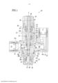
[0017] [Figura 1] A Figura 1 é uma vista em corte de uma válvula de controle de taxa de fluxo de acordo com a presente invenção com um elemento de válvula da mesma que está em um estado de abertura.[0017] [Figure 1] Figure 1 is a cross-sectional view of a flow rate control valve according to the present invention with a valve element thereof that is in an open state.
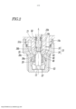
[0018] [Figura 2] A Figura 2 é uma ampliação de uma parte que inclui uma porção de válvula ilustrada na Figura 1.[0018] [Figure 2] Figure 2 is an enlargement of a part that includes a valve portion illustrated in Figure 1.
[0019] [Figura 3] A Figura 3 é uma vista em corte da válvula de controle de taxa de fluxo de acordo com a presente invenção com o elemento de válvula da mesma que está em estado de fechamento.[0019] [Figure 3] Figure 3 is a cross-sectional view of the flow rate control valve according to the present invention with the valve element thereof being in a closed state.
[0020] [Figura 4] A Figura 4 é uma vista frontal de uma porção de ajuste de taxa de fluxo e elementos associados fornecidos ao redor.[0020] [Figure 4] Figure 4 is a front view of a flow rate adjustment portion and associated elements provided therearound.
[0021] [Figura 5] A Figura 5 é um diagrama de circuito que ilustra um circuito de controle exemplificativo em que um cilindro de pressão de fluido de dupla ação é controlado usando-se a válvula de controle de fluido de acordo com a presente invenção.[0021] [Figure 5] Figure 5 is a circuit diagram illustrating an exemplary control circuit in which a double-acting fluid pressure cylinder is controlled using the fluid control valve in accordance with the present invention .
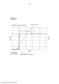
[0022] [Figura 6] A Figura 6 é um gráfico que ilustra a relação entre a pressão de fluido em cada uma dentre uma câmara de pressão de lado de cabeça e uma câmara de pressão de lado de haste e o comprimento do curso de um pistão quando o fluido comprimido sofre refluxo da câmara de pressão de lado de cabeça para a câmara de pressão de lado de haste.[0022] [Figure 6] Figure 6 is a graph illustrating the relationship between fluid pressure in each of a head-side pressure chamber and a rod-side pressure chamber and the stroke length of a piston when the compressed fluid refluxes from the head-side pressure chamber to the rod-side pressure chamber.
[0023] Uma modalidade da válvula de controle de fluido de acordo com a presente invenção será agora descrita em detalhes com referência aos desenhos. A válvula de controle de fluido de acordo com a presente invenção deve ser conectada a uma câmara de pressão de um atuador de pressão de fluido e é dessa forma utilizada para extração e reutilização do ar de escape da câmara de pressão. No presente documento, um caso exemplificativo ilustrado na Figura 5 será descrito em que uma válvula de controle de fluido 10 de acordo com uma modalidade da presente invenção é conectada a um cilindro de pressão de fluido de dupla ação 1 que inclui um pistão 1c e uma haste 1d, e quando o pistão 1c é movido para frente, o ar de escape que é descarregado da segunda câmara de pressão 1b disposto em uma lado de haste do cilindro de pressão de fluido 1 sofre refluxo em uma primeira câmara de pressão 1a disposta em um lado de cabeça, por meio da qual o ar de escape é reutilizado.[0023] One embodiment of the fluid control valve according to the present invention will now be described in detail with reference to the drawings. The fluid control valve according to the present invention must be connected to a pressure chamber of a fluid pressure actuator and is thus used for extracting and reusing exhaust air from the pressure chamber. In the present document, an exemplary case illustrated in Figure 5 will be described in which a
[0024] Como ilustrado nas Figuras 1 a 5, a válvula de controle de fluido 10 inclui uma primeira porta 11 para a conexão a uma válvula de comutação 3, uma segunda porta 12 para a conexão à segunda câmara de pressão 1b, uma terceira porta 13 para a conexão à primeira câmara de pressão 1a, uma passagem de fornecimento de ar 14 que permite que a primeira porta 11 e a segunda porta 12 comuniquem-se, e uma passagem de ar de escape 15 que permite que a segunda porta 12 e a terceira porta 13 comuniquem-se.[0024] As illustrated in Figures 1 to 5, the
[0025] As primeira e terceira portas 11 a 13, a passagem de fornecimento de ar 14 e a passagem de ar de escape 15 são dispostas em um compartimento de válvula 50. O compartimento de válvula 50 inclui um bloco principal 51. O bloco principal 51 inclui uma porção de tronco tubular 51a que tem um eixo geométrico L (um eixo geométrico que estende-se verticalmente nas Figuras 1 a 3, e cujo lado superior é definido como o primeiro lado de extremidade e cujo lado inferior é definido como o lado da segunda extremidade), e primeira e segunda porções de ramificação 51b e 51c que se estendem da parede lateral da porção de tronco 51a. O compartimento de válvula 50 ainda inclui um primeiro bloco de primeira porta 52 hermeticamente instalado na primeira porção de ramificação 51b e que inclui a primeira porta 11 e um bloco de segunda porta 53 hermeticamente instalado no lado da segunda extremidade da porção de tronco 51a e que inclui a segunda porta 12. A terceira porta 13 é disposta na segunda porção de ramificação 51c. Além disso, uma tampa de extremidade 54 é disposta no primeiro lado de extremidade da porção de tronco 51a de maneira a ser giratória em torno do eixo geométrico L.[0025] The first and
[0026] A passagem de fornecimento de ar 14 inclui uma primeira passagem de fornecimento de ar 14a que passa pelo bloco da primeira porta 52, uma segunda passagem de fornecimento de ar 14b que passa pela primeira porção de ramificação 51b, e uma terceira passagem de fornecimento de ar 14c disposta no lado da segunda extremidade da porção de tronco 51a. A terceira passagem de fornecimento de ar 14c é provida de uma primeira válvula de retenção 20 que permite que o fluido comprimido fornecido de uma fonte de pressão de fluido 2 flua do lado da primeira porta 11 para o lado da segunda porta 12 mas impede que o fluido comprimido flua do lado da segunda porta 12 para o lado da primeira porta 11.[0026] The
[0027] A passagem de ar de escape 15 inclui uma primeira passagem de ar de escape 15a que passa pela segunda porção de ramificação 51c, e uma segunda passagem de ar de escape 15b disposta no lado da segunda extremidade e um orifício de inserção de haste 22, que será descrito abaixo. A segunda passagem de ar de escape 15b é provido de uma segunda válvula de retenção 21 que permite o fluxo do lado da segunda porta 12 para o lado da terceira porta 13 mas impede o fluxo do lado da terceira porta 13 para o lado da segunda porta 12.[0027] The
[0028] A porção de tronco 51a é provida do orifício de inserção de haste 22 que serve como um orifício de válvula definido por uma parede periférica interior 51d da porção de tronco 51a. O orifício de inserção de haste 22 passa pela porção de tronco 51a na direção de lado longo (a direção da linha do eixo geométrico L). A porção de tronco 51a é ainda provida de um elemento de válvula 30 que é deslizável na direção da linha do eixo geométrico L no orifício de inserção de haste 22. O elemento de válvula 30 é previsto para abrir e fechar uma passagem da segunda porta 12 para a passagem de ar de escape 15b, isto é, uma passagem da segunda porta 12 para a terceira porta 13. O elemento de válvula 30 tem um formato de haste com um corte transversal substancialmente circular e é giratório em torno da linha de eixo geométrico L no orifício de inserção de haste 22. O elemento de válvula 30 inclui uma porção de eixo 32 posicionada no primeiro lado de extremidade, isto é, o lado proximal; e uma porção de válvula 31 posicionada no lado da segunda extremidade, isto é, o lado distal, na direção da linha do eixo geométrico L. A porção de eixo 32 tem uma primeira superfície de recebimento de pressão que causa uma ação da pressão de fluido na primeira porta 11 em uma direção de fechamento do elemento de válvula 30 (uma direção de segunda extremidade). A porção de eixo 31 tem uma segunda superfície de recebimento de pressão que causa uma ação da pressão de fluido na segunda porta 12 em uma direção de abertura do elemento de válvula 30 (uma direção de primeira extremidade). Independentemente do comportamento de abertura e fechamento do elemento de válvula 30, a área de recebimento de pressão da primeira superfície de recebimento de pressão na direção da linha de eixo geométrico L é sempre maior que a área de recebimento de pressão da segunda superfície de recebimento de pressão na direção da linha de eixo geométrico L.[0028] The
[0029] O orifício de inserção de haste 22 inclui uma porção de inserção de haste 22a posicionada no primeiro lado de extremidade e através do qual a porção de eixo 32 estende- se, e uma porção de inserção de válvula 22b posicionada no lado da segunda extremidade e através da qual a porção de válvula 31 estende-se. A porção de inserção de eixo 22a e a porção de inserção de válvula 22b são hermeticamente separadas uma da outra por um membro de vedação 60 disposto na parede de partição 23 que separa as duas. A porção de inserção de válvula 22b tem um diâmetro de furo maior que o diâmetro máximo da porção de válvula 31 (o diâmetro de uma parte de diâmetro grande 33 a ser descrito abaixo). Um vão disposto entre a parede periférica interior 51d da porção de inserção de válvula 22b e a superfície periférica exterior da porção de válvula 31 (isto é, a superfície periférica exterior da parte de diâmetro grande 33) serve como uma segunda passagem de ar de escape 15b.[0029] The
[0030] A porção de tronco 51a tem uma ranhura 57 na superfície periférica externa da mesma no lado da segunda extremidade. A primeira válvula de retenção 20 é encaixada na ranhura 57. A porção de inserção de válvula 22b do orifício de inserção de haste 22 tem uma projeção anular 48 em uma posição no lado da segunda extremidade (isto é, no lado mais próximo à segunda porta 12) em relação à segunda válvula de retenção 21. A projeção 48 projeta para dentro (na direção radial) a partir da parede periférica interna 51d. Uma superfície da projeção 48 que é voltada para o primeiro lado de extremidade forma uma sede de válvula 44. A porção de válvula 31 entra em contato com e move-se para longe da sede de válvula 44. A periferia interna da projeção 48 forma uma parte de estrangulamento 46 na qual uma parte de diâmetro pequeno 34, que será descrita abaixo, da porção de válvula 31 é inserível.[0030] The
[0031] A porção de válvula 31 inclui a parte de diâmetro grande 33, que é contínua à porção de eixo 32 e tem um formato redondo-colunar, e a parte de diâmetro pequeno 34, que é contínua ao lado da segunda extremidade da parte de diâmetro grande 33 e cujo diâmetro máximo é menor que aquele da parte de diâmetro grande 33. A parte de diâmetro grande 33 tem uma ranhura 58 na superfície periférica externa da mesma. A segunda válvula de retenção 21 descrita acima é encaixada na ranhura 58. A parte de diâmetro pequeno 34 tem um formato afunilado cujo diâmetro é gradualmente reduzido em direção à segunda extremidade, e tem uma face de extremidade distal 36a na ponta da mesma. A direção da linha do eixo geométrico L do elemento de válvula 30 corresponde à direção do normal para a face da extremidade distal 36a. A conexão, isto é, a fronteira, entre a parte de diâmetro grande 33 e a parte de diâmetro pequeno 34 tem uma ranhura 36b que forma um degrau. Um membro de vedação 35 é encaixado na ranhura 36b.[0031] The
[0032] O membro de vedação 35 é disposto na porção de válvula 31 de maneira a entrar em contato com a sede de válvula 44 quando o elemento de válvula 30 é movido para o lado da segunda extremidade e de maneira a estar distante da sede de válvula 44 quando o elemento de válvula 30 é movido para o primeiro lado de extremidade. Portanto, comparando um estado em que o membro de vedação 35 e a sede de válvula 44 estão em contato e um estado em que o membro de vedação 35 e a sede de válvula 44 estão distantes uma da outra, isto é, comparando a porção de válvula 31 que está em um estado de fechamento e a porção de válvula 31 que está em um estado de abertura, a porção de válvula 31 que está no estado de abertura tem uma área maior (área de recebimento de pressão) na segunda superfície de recebimento de pressão da mesmo sobre a qual a pressão de fluido age na direção da primeira extremidade. Consequentemente, a força que age no elemento de válvula 30 na direção da primeira extremidade é aumentada e a capacidade de resposta após o comportamento de abertura da porção de válvula 31 é melhorada.[0032] The sealing
[0033] A porção de eixo 32 inclui uma parte de corpo 38 contínua ao primeiro lado de extremidade da parte de diâmetro grande 33 e que tem um diâmetro maior que a parte de diâmetro grande 33, e uma parte de bastão 39 contínua ao primeiro lado de extremidade da parte de corpo 38 e projetando-se de uma abertura disposta no primeiro lado de extremidade na porção de tronco 51a. A parte de corpo 38 inclui um pistão 37, na periferia externa da qual um membro de vedação 62 é provido. O pistão 37 separa a porção de inserção de eixo 22a do orifício de inserção de haste 22 descrito acima em uma câmara de primeira seção 70a disposta no primeiro lado de extremidade e uma câmara de segunda seção 70b disposta no lado da segunda extremidade. Na presente modalidade, o membro de vedação 62 disposto no pistão 37 serve como uma válvula de retenção que permite que um fluido flua do lado da câmara de segunda seção 70b para o lado da câmara de primeira seção 70a mas impede que o fluido flua do lado da câmara de primeira seção 70a para o lado da câmara de segunda seção 70b. Consequentemente, a câmara de primeira seção 70a serve como uma câmara de pressão de pistão para mover o pistão 37 na direção da segunda extremidade, enquanto a câmara de segunda seção 70b é aberta para a atmosfera.[0033] The
[0034] A parte de bastão 39 é encaixada em um orifício de encaixe 59 disposto na tampa de extremidade 54. A tampa de extremidade 54 é fixada em relação à parte de bastão 39 na direção em torno da linha do eixo geométrico L. Isto é, quando a tampa de extremidade 54 é girada em torno da linha do eixo geométrico L, a parte de bastão 39 também é girada.[0034] The
[0035] Um estator anular 41 (um anel de came que tem uma superfície de came 41a que é inclinada de forma helicoidal) é encaixado na porção de inserção de eixo 22a e é encaixado em uma posição no primeiro lado de extremidade em relação ao pistão 37. A porção de eixo 32 do elemento de válvula 30 estende-se através do estator 41 de maneira a ser deslizável na direção da linha do eixo geométrico L e giratório em trono da linha do eixo geométrico L. Como ilustrado na Figura 4, uma superfície do estator 41 que está no lado da segunda extremidade forma a superfície de came inclinada 41a que se estende ao redor da porção de eixo 32. A superfície de came inclinada 41a volta-se para o pistão 37 e estende-se de forma helicoidal ao redor da linha do eixo geométrico L. A parte de corpo 38 da porção de eixo 32 tem uma aba de batente 43 que se projeta da parede periférica exterior da mesma e estende-se de uma superfície de lado de primeira extremidade 37a do pistão 37 para o estator 41.[0035] An annular stator 41 (a cam ring having a
[0036] Quando a tampa de extremidade 54 é girada, a parte de corpo 38 é girada junto com a tampa de extremidade 54 com o estator 41 fixado à porção de tronco 51a. Portanto, a aba de batente 43 que se projeta da parte de corpo 38 gira em relação ao estator 41 e em torno da linha do eixo geométrico L. Note que a superfície de came inclinada 41a do estator 41 estende-se de forma helicoidal e forma uma superfície inclinada. Portanto, ao ajustar a posição para qual a tampa de extremidade 54 é girada, a posição em que a aba de batente 43 entra em contato com a superfície de came inclinada 41a, isto é, o comprimento do curso do pistão 37 na direção da primeira extremidade, pode ser ajustada. Consequentemente, a quantidade de redução na parte de estrangulamento 46 quando o elemento de válvula 30 é movido para a posição de abertura no primeiro lado de extremidade, isto é, a taxa de fluxo do fluido que flui da segunda porta 12 e passa pela parte de estrangulamento 46 para a passagem de ar de escape 15, pode ser ajustada. Dessa forma, a superfície de came inclinada 41a e a aba de batente 43 formam uma porção de ajuste de taxa de fluxo 47 de acordo com a presente invenção.[0036] When the
[0037] Note que uma tampa anular 42 é hermeticamente encaixada na porção de inserção de eixo 22a enquanto que une o primeiro lado de extremidade ao estator 41, e a porção de eixo 32 do elemento de válvula 30 estende-se hermeticamente através do membro de tampa 42 de maneira a ser deslizável na direção da linha do eixo geométrico L e giratório em torno da linha do eixo geométrico L.[0037] Note that an
[0038] A câmara da primeira seção 70a e a passagem de fornecimento de ar 14b são conectadas uma a outra com uma passagem-piloto 71 que permite que o fluido comprimido da primeira porta 11 seja fornecido. Portanto, quando o fluido comprimido fornecido para a porta 11 flui através da passagem de fornecimento de ar 14 para a segunda porta 12, parte do fluido comprimido é fornecido para a câmara de primeira seção 70a através da passagem-piloto 71. Depois, a pressão de fluido do fluido comprimido fornecido para a câmara de primeira seção 70a age na primeira superfície de recebimento de pressão posicionada no primeiro lado de extremidade em relação ao pistão 37. Consequentemente, o pistão 37 é movido na direção da segunda extremidade, isto é, na direção em que o elemento de válvula 30 é fechado.[0038] The
[0039] A câmara de segunda seção 70b é provida de uma mola de compressão 25 que aplica uma força que age na direção da primeira extremidade (isto é, a direção de abertura do elemento de válvula 30) sobre o pistão 37. A mola de compressão 25 é disposta em um estado comprimido entre uma parte de recebimento de mola 24, que é ligada à conexão entre a porção de inserção de eixo 22a e a porção de inserção de válvula 22b (isto é, a parede de partição 23), e uma superfície de lado de segunda extremidade 37b do pistão 37.[0039] The
[0040] Dessa forma, a primeira superfície de recebimento de pressão da porção de eixo 32, a segunda superfície de recebimento de pressão da porção de válvula 31 e a mola de compressão 25 formam uma porção de operação de abertura e fechamento de acordo com a presente invenção.[0040] In this way, the first pressure-receiving surface of the
[0041] O módulo de elasticidade da mola de compressão 25 deve ser determinada adequadamente com base em fatores como a pressão do fluido comprimido aplicada, as características necessárias do atuador de pressão de fluido para ser conectado e assim por diante. Note que quando a porção de válvula 31 está encaixada e está no estado de fechamento, a soma das forças na direção da primeira extremidade que são geradas pela mola de compressão 25 e pela pressão de fluido que age na segunda superfície de recebimento de pressão é definida para ser menor que a força na direção da segunda extremidade que é gerada pela pressão de fluido que age na primeira superfície de recebimento de pressão.[0041] The modulus of elasticity of the
[0042] A mola de compressão 25 não é necessariamente fornecida e pode ser omitida. Nesse caso, o elemento de válvula 30 pode ser movido na direção de abertura com o uso apenas da pressão de fluido na segunda porta 12 que age na segunda superfície de recebimento de pressão.[0042] The
[0043] Agora, comportamentos específicos da dupla válvula de controle de fluido 10 em um caso ilustrado na Figura 5 serão descritos, em que a válvula de controle de fluido 10 é conectada ao cilindro de pressão de fluido de dupla ação 1 que inclui o pistão 1c e a haste 1d, por meio dos quais, quando o pistão 1c é movido para frente, o ar de escape descarregado da segunda câmara de pressão 1b disposta no lado de haste do cilindro de pressão de fluido 1 sofre refluxo para a câmara de pressão de fluido 1a disposta no lado de cabeça.[0043] Now, specific behaviors of the double
[0044] Nesse caso, a válvula de controle de fluido 10 é conectada entre a válvula de comutação 3, que é conectada à fonte de pressão de fluido 2, e o cilindro de pressão de fluido 1, que inclui a primeira câmara de pressão 1a no lado de cabeça e a segunda câmara de pressão 1b no lado de haste. A válvula de comutação 3 e o cilindro de pressão de fluido 1 são conectados com uma primeira passagem 4a que conecta a válvula de comutação 3 à primeira porta 11 da válvula de controle de fluido 10, uma segunda passagem 4b que conecta a segunda câmara de pressão 1b à segunda porta 12 da válvula de controle de fluido 10, uma terceira passagem 4c que conecta a primeira câmara de pressão 1a à válvula de comutação 3, e uma quarta passagem 4d que conecta a terceira passagem 4c à terceira porta da válvula de controle de fluido 10. A terceira passagem 4c é provida de uma válvula de acelerador 5 em uma posição entre a conexão da mesma para a quarta passagem 4d e a primeira câmara de pressão 1a. A válvula de acelerador 5 é de um tipo de controle sem medida para ajustar a taxa de fluxo do fluido comprimido que é descarregado da primeira câmara de pressão 1a.[0044] In this case, the
[0045] A posição da válvula de comutação 3 é seletivamente alternável entre uma primeira posição em que o fluido comprimido da fonte de pressão de fluido 2 é fornecido para a segunda câmara de pressão 1b e uma segunda posição em que o fluido comprimido da fonte de pressão de fluido 2 é fornecido para a primeira câmara de pressão 1a.[0045] The position of the switching
[0046] Consequentemente, um caso em que a válvula de comutação 3 é alternada para a primeira posição, isto é, um caso em que a haste 1d do cilindro de pressão de fluido 1 é movida para frente, será descrito primeiro.[0046] Accordingly, a case where the
[0047] O fluido comprimido fornecido da fonte de pressão de fluido 2 é fornecido para a primeira porta 11 da válvula de controle de fluido 10 descrita acima através da primeira passagem 4a. O fluido comprimido fornecido para a primeira porta 11 flui através da primeira passagem de fornecimento de ar 14a e da segunda passagem de fornecimento de ar 14b, nessa ordem, e parte do fluido comprimido é fornecido para a passagem-piloto 71 descrita acima enquanto o restante é fornecido para a terceira passagem de fornecimento de ar 14c. O fluido comprimido fornecido para a terceira passagem de fornecimento de ar 14c flui através da primeira válvula de retenção 20, é enviado da segunda porta 12 e é fornecido para a segunda câmara de pressão 1b do cilindro de pressão de fluido 1. Enquanto isso, o ar comprimido na primeira câmara de pressão 1b do cilindro de pressão de fluido 1 é liberado para atmosfera através da válvula de acelerador 5 e da válvula de comutação 3.[0047] The compressed fluid supplied from the
[0048] O fluido comprimido que flui para a passagem- piloto 71 é fornecido para a câmara de primeira seção 70a que serve como a câmara de pressão de pistão descrita acima. Nessa etapa, a pressão do fluido comprimido que está sendo fornecida para a câmara de primeira seção 70a e a pressão de fluido do fluido comprimido que está sendo enviada da segunda porta 12 são substancialmente a mesma. Contudo, visto que há uma diferença na área de recebimento de pressão, a força gerada na direção da primeira extremidade (na direção de abertura do elemento de válvula 30) pela pressão de fluido que age na segunda superfície de recebimento de pressão da porção de válvula 31 é menor que a força gerada na direção da segunda extremidade (na direção de fechamento do elemento de válvula 30) pela pressão de fluido que age na primeira superfície de recebimento de pressão da porção de eixo 32. Além disso, a diferença entre as forças geradas pelas pressões de fluido respectivas é sempre definida para um valor maior que a força gerada na direção da primeira extremidade pela mola de compressão 25 coma porção de válvula 31 que está encaixada e em estado de fechamento. Consequentemente, como ilustrado na Figura 3, enquanto o elemento de válvula 30 é encaixado na sede de válvula 44, a passagem entre a segunda porta 12 e a passagem de ar de escape 15, isto é, a passagem da segunda porta 12 para a terceira porta 13, é fechada.[0048] The compressed fluid flowing into the
[0049] Agora, um caso em que a válvula de comutação 3 é alternada para a segunda posição como ilustrado na Figura 5, isto é, um caso em que a haste 1d do cilindro de pressão de fluido 1 é movida para frente, será descrito.[0049] Now, a case where the switching
[0050] Nesse caso, a primeira passagem 4a é aberta para a atmosfera através da válvula de comutação 3. Portanto, na válvula de controle de fluido 10, uma porção da passagem de fornecimento de ar 14 que se estende da primeira porta 11 para a primeira válvula de retenção 20, a passagem-piloto 71, e a câmara de primeira seção 70a são também abertas para a atmosfera. Em contrapartida, o fluido comprimido em uma porção da primeira válvula de retenção 20 para a segunda câmara de pressão 1b do cilindro de pressão de fluido 1 é impedido de fluir para o lado da primeira porta 11 pela primeira válvula de retenção 20. Portanto, a pressão de fluido do fluido comprimido age na segunda superfície de recebimento de pressão da porção de válvula 31 e estimula o elemento de válvula 30 na direção de abertura. Simultaneamente, a mola de compressão 25 está estimulando o elemento de válvula 30 na direção de abertura. Portanto, como ilustrado na Figura 1, o elemento de válvula 30 é distanciado da sede de válvula 44 e a passagem entre a segunda porta 12 e a passagem de ar de escape 15, isto é, a passagem da segunda porta 12 para a terceira porta 13, é aberta.[0050] In that case, the
[0051] Enquanto isso, a primeira câmara de pressão 1a comunica-se com a fonte de pressão de fluido 2. Portanto, o fluido comprimido é fornecido para a primeira câmara de pressão 1a disposta no lado de cabeça. Consequentemente, como ilustrado na Figura 6, a pressão na primeira câmara de pressão 1a disposta no lado de cabeça aumenta rapidamente para um valor predeterminado, e o pistão 1c do cilindro de pressão de fluido 1 começa a mover-se para o lado de haste (o lado direito na Figura 5).[0051] Meanwhile, the
[0052] Então, com o movimento do pistão 1c para o lado de haste, o volume da segunda câmara de pressão 1b é reduzido e a pressão na segunda câmara de pressão 1b aumenta levemente. Contudo, visto que a área de recebimento de pressão do pistão 1c no lado da primeira câmara de pressão 1a é maior que a área de recebimento de pressão do pistão 1c no lado da segunda câmara de pressão 1b pela área de corte transversal da haste 1d, o pistão 1c continua a mover-se para o lado de haste. Durante esse processo, o fluido comprimido descarregado da segunda câmara de pressão 1b flui da passagem de ar de escape 15, passa pela terceira porta 13 e flui para a quarta passagem 4d. Contudo, visto que a pressão do fluido comprimido descarregado da segunda câmara de pressão 1b é levemente maior que a pressão na primeira câmara de pressão 1a como descrito acima, o fluido comprimido na quarta passagem 4d sofre refluxo para a primeira câmara de pressão 1a através da terceira passagem 4c. Para ajustar a velocidade em que a haste 1d é movida para frente, a quantidade de redução na parte de estrangulamento 46, isto é, a taxa de fluxo do ar de escape da segunda câmara de pressão 1b que flui através da parte de estrangulamento 46, apenas necessita ser ajustada pela rotação da tampa de extremidade 54.[0052] Then, with the movement of the
[0053] Como descrito acima, a válvula de controle de taxa de fluxo 10 de acordo com a presente modalidade é configurada para que o fluido comprimido possa ser fornecido da primeira porta 11 para a segunda câmara de pressão 1b através da segunda porta 12 pela conexão da segunda porta 12 com a segunda câmara de pressão 1b do cilindro de pressão de fluido 1 que serve como o atuador de pressão de fluido, e para que o ar de escape descarregado da segunda câmara de pressão 1b possa ser extraído da terceira porta 13 através da segunda porta 12. Portanto, o ar de escape pode ser reutilizado de maneira eficiente. Em particular, no cilindro de pressão de fluido de dupla ação 1 descrito acima, ao conectar a segunda porta 12 à segunda câmara de pressão 1b enquanto conecta-se a terceira porta 13 à primeira câmara de pressão 1a, o ar de escape da segunda câmara de pressão 1b pode sofrer refluxo para a primeira câmara de pressão 1a quando a haste 1d é movida para frente, por meio da qual o consumo do fluido comprimido pode ser suprimido.[0053] As described above, the flow
[0054] Além disso, visto que o elemento de válvula 30 pode ser aberto e fechado com o uso do ar comprimido para ativação do cilindro de pressão de fluido 1, o custo de fabricação e o custo de funcionamento podem ser suprimidos.[0054] Furthermore, since the
[0055] Na válvula de controle de taxa de fluxo 10 de acordo com a presente modalidade, a porção de válvula em formato de haste 31 inclui a parte de diâmetro grande 33 e a parte de diâmetro pequeno 34 e o membro de vedação 35 que entra em contato com e move para longe da sede de válvula 44 é disposto na fronteira entre as duas. Portanto, comparando o estado em que o membro de vedação 35 e a sede de válvula 44 estão em contato e o estado em que o membro de vedação 35 e a sede de válvula 44 estão distanciados, isto é, comparando a porção de válvula 31 que está no estado de fechamento e a porção de válvula 31 que está no estado de abertura, a porção de válvula 31 que está nesse último estado tem uma área maior (área de recebimento de pressão) na segunda superfície de recebimento de pressão da mesma sobre a qual a pressão de fluido age na direção da primeira extremidade. Consequentemente, a força que age no elemento de válvula 30 na direção da primeira extremidade é aumentada, e a capacidade de resposta após o comportamento de abertura da porção de válvula 31 é melhorada.[0055] In the flow
[0056] Além disso, na válvula de controle de taxa de fluxo 10 de acordo com a presente modalidade, a porção de válvula 31 é uma válvula de agulha e a superfície de came inclinada 41a do estator 41 que se estende de forma helicoidal e a aba de batente 43 que está em contato com a mesma são giratórias em relação uma a outra em torno da linha de eixo geométrico L. Portanto, ao girar o elemento de válvula 30 e dessa forma ajustar a posição em que a superfície de came inclinada 41a e a aba de batente 43 entram em contato, a taxa de fluxo do ar de escape na parte de estrangulamento 46 quando o elemento de válvula 30 está no estado de abertura pode ser controlada facilmente.[0056] Furthermore, in the flow
[0057] Embora uma modalidade da válvula de controle de taxa de fluxo 10 de acordo com a presente invenção tenha sido descrita em detalhes acima, a presente invenção não está limitada à modalidade acima e várias mudanças de projeto podem ser feitas sem desviar da essência da presente invenção. Por exemplo, embora a porção de válvula 31 de acordo com a presente modalidade é uma válvula de agulha, a porção de válvula 31 não está necessariamente limitada a isso e pode ser uma válvula de qualquer outro tipo como uma válvula de gatilho.[0057] Although one embodiment of the flow
[0058] Além disso, embora a presente modalidade diga respeito a um caso em que a superfície de came inclinada 41a é fixada em relação ao orifício de inserção de haste 22 e a aba de batente 43 a entrar em contato com a mesma ser fixada ao elemento de válvula 30, a superfície de came inclinada 41a pode alternativamente ser fixada em relação ao elemento de válvula 30 e a aba de batente 43 ser fixada ao orifício de inserção de haste. LISTA DE REFERÊNCIAS NUMÉRICAS 1 cilindro de pressão de fluido 2 a primeira câmara de pressão 3 b segunda câmara de pressão 4 fonte de pressão de fluido 5 válvula de comutação 10 válvula de controle de fluido 11 primeira porta 12 segunda porta 13 terceira porta 14 passagem de fornecimento de ar 15 passagem de ar de escape 15b segunda passagem de ar de escape (vão) 20 primeira válvula de retenção 21 segunda válvula de retenção 22 orifício de inserção de haste (orifício de válvula) 30 elemento de válvula 31 porção de válvula 32 porção de eixo 33 parte de diâmetro grande 34 parte de diâmetro pequeno 35 membro de vedação 37 pistão 41 estator 41a superfície de came inclinada 43 aba de batente 44 sede de válvula 46 parte de estrangulamento 47 porção de ajuste de taxa de fluxo 70a câmara de primeira seção (câmara de pressão de pistão) 71 passagem-piloto[0058] Furthermore, although the present embodiment concerns a case where the
Claims (8)
Applications Claiming Priority (3)
| Application Number | Priority Date | Filing Date | Title |
|---|---|---|---|
| JP2015-212084 | 2015-10-28 | ||
| JP2015212084A JP6551740B2 (en) | 2015-10-28 | 2015-10-28 | Fluid control valve |
| PCT/JP2016/081039 WO2017073439A1 (en) | 2015-10-28 | 2016-10-20 | Fluid control valve |
Publications (2)
| Publication Number | Publication Date |
|---|---|
| BR112018008240A2 BR112018008240A2 (en) | 2018-10-23 |
| BR112018008240B1 true BR112018008240B1 (en) | 2023-01-10 |
Family
ID=58631483
Family Applications (1)
| Application Number | Title | Priority Date | Filing Date |
|---|---|---|---|
| BR112018008240-6A BR112018008240B1 (en) | 2015-10-28 | 2016-10-20 | FLUID CONTROL VALVE |
Country Status (10)
| Country | Link |
|---|---|
| US (1) | US10514048B2 (en) |
| JP (1) | JP6551740B2 (en) |
| KR (1) | KR20180071261A (en) |
| CN (1) | CN108350909B (en) |
| BR (1) | BR112018008240B1 (en) |
| DE (1) | DE112016004954T5 (en) |
| MX (1) | MX2018005112A (en) |
| RU (1) | RU2720870C2 (en) |
| TW (1) | TWI707101B (en) |
| WO (1) | WO2017073439A1 (en) |
Families Citing this family (8)
| Publication number | Priority date | Publication date | Assignee | Title |
|---|---|---|---|---|
| CN113167298B (en) * | 2018-11-21 | 2023-07-21 | Smc 株式会社 | Cylinder driving device and flow path unit |
| JP6960585B2 (en) * | 2018-12-03 | 2021-11-05 | Smc株式会社 | Flow controller and drive unit equipped with it |
| WO2020157829A1 (en) * | 2019-01-29 | 2020-08-06 | 株式会社エイシン技研 | Servo valve unit |
| CN110440037A (en) * | 2019-05-14 | 2019-11-12 | 开能健康科技集团股份有限公司 | Control valve fitment and the water softening device comprising it |
| JP7076686B2 (en) * | 2019-09-06 | 2022-05-30 | Smc株式会社 | Flow controller and drive unit equipped with it |
| JP7447689B2 (en) * | 2020-06-10 | 2024-03-12 | Smc株式会社 | gas cylinder |
| JP2022010920A (en) * | 2020-06-29 | 2022-01-17 | オムロン株式会社 | Robotic joint structure |
| CN117267417B (en) * | 2023-11-10 | 2024-02-02 | 靖江市新世纪液压件制造有限公司 | Safety valve capable of being automatically opened by overpressure to perform pressure regulation |
Family Cites Families (16)
| Publication number | Priority date | Publication date | Assignee | Title |
|---|---|---|---|---|
| US3654835A (en) * | 1970-05-25 | 1972-04-11 | Ato Inc | Regeneration valve |
| FR2544403B1 (en) * | 1983-04-12 | 1985-08-09 | Legris | AUTOMATIC COMPRESSED AIR SAVING DEVICE |
| LU88277A1 (en) * | 1993-05-27 | 1994-12-01 | Hydrolux Sarl | Pilot operated servo valve |
| JPH0842511A (en) | 1994-08-02 | 1996-02-13 | Konan Denki Kk | Pneumatic cylinder device |
| JP3400557B2 (en) * | 1994-08-10 | 2003-04-28 | 大阪瓦斯株式会社 | Valve drive |
| JP3778634B2 (en) | 1996-11-22 | 2006-05-24 | Smc株式会社 | Speed controller with pilot check valve |
| JP3598235B2 (en) * | 1999-03-10 | 2004-12-08 | Smc株式会社 | Pressure flow control valve |
| JP3558556B2 (en) * | 1999-03-10 | 2004-08-25 | Smc株式会社 | Pressure flow control valve |
| JP2001116008A (en) * | 1999-10-18 | 2001-04-27 | Smc Corp | Pressure regulating mechanism |
| DE10253340B4 (en) * | 2002-04-26 | 2007-02-15 | Volkmann Gmbh | Actuation valve for a two-sided effective pneumatic cylinder and use of such an actuating valve for by means of pneumatic cylinders creel |
| RU2347127C1 (en) * | 2007-07-02 | 2009-02-20 | Открытое акционерное общество "Павловский машиностроительный завод ВОСХОД" (ОАО "ПМЗ ВОСХОД") | Valve |
| CN202109077U (en) * | 2011-06-07 | 2012-01-11 | 谢志平 | Pneumatic solar water heater air evacuation valve |
| CN104718150B (en) * | 2012-10-18 | 2016-10-12 | 株式会社丰田自动织机 | Lowering or hoisting gear |
| NL2010952C2 (en) * | 2013-06-11 | 2014-12-15 | Demolition And Recycling Equipment B V | HYDRAULIC CYLINDER FOR EXAMPLE FOR USE IN A HYDRAULIC TOOL. |
| CN105518310B (en) * | 2013-09-02 | 2017-11-07 | Smc株式会社 | Control valve for fluids |
| CN204164076U (en) * | 2014-10-28 | 2015-02-18 | 徐工集团工程机械股份有限公司 | A kind of load-sensitive duty valve and multi-way valve, hydraulic system, mini-excavator |
-
2015
- 2015-10-28 JP JP2015212084A patent/JP6551740B2/en active Active
-
2016
- 2016-10-18 TW TW105133574A patent/TWI707101B/en not_active IP Right Cessation
- 2016-10-20 US US15/771,139 patent/US10514048B2/en active Active
- 2016-10-20 DE DE112016004954.4T patent/DE112016004954T5/en active Pending
- 2016-10-20 KR KR1020187010472A patent/KR20180071261A/en not_active Application Discontinuation
- 2016-10-20 RU RU2018119090A patent/RU2720870C2/en active
- 2016-10-20 WO PCT/JP2016/081039 patent/WO2017073439A1/en active Application Filing
- 2016-10-20 CN CN201680063009.4A patent/CN108350909B/en active Active
- 2016-10-20 BR BR112018008240-6A patent/BR112018008240B1/en active IP Right Grant
- 2016-10-20 MX MX2018005112A patent/MX2018005112A/en unknown
Also Published As
| Publication number | Publication date |
|---|---|
| US10514048B2 (en) | 2019-12-24 |
| MX2018005112A (en) | 2018-06-06 |
| CN108350909B (en) | 2020-04-10 |
| TW201727109A (en) | 2017-08-01 |
| US20180355892A1 (en) | 2018-12-13 |
| KR20180071261A (en) | 2018-06-27 |
| DE112016004954T5 (en) | 2018-08-02 |
| RU2720870C2 (en) | 2020-05-13 |
| RU2018119090A3 (en) | 2020-03-03 |
| TWI707101B (en) | 2020-10-11 |
| JP2017082916A (en) | 2017-05-18 |
| JP6551740B2 (en) | 2019-07-31 |
| CN108350909A (en) | 2018-07-31 |
| BR112018008240A2 (en) | 2018-10-23 |
| RU2018119090A (en) | 2019-11-28 |
| WO2017073439A1 (en) | 2017-05-04 |
Similar Documents
| Publication | Publication Date | Title |
|---|---|---|
| BR112018008240B1 (en) | FLUID CONTROL VALVE | |
| CN105518310B (en) | Control valve for fluids | |
| MXPA06011612A (en) | Flow switchable check valve. | |
| JP2017082916A5 (en) | ||
| BRPI1102944A2 (en) | Hydraulic valve | |
| JP2008202724A (en) | Direction control valve system and direction control valve system block furnished with plurality of direction control valve system | |
| CN108150475A (en) | Load sensing multi-way valve group and with its walking machine hydraulic system | |
| CN105814321A (en) | Fluid pressure control device | |
| WO2014111603A1 (en) | Knife gate valve | |
| JP5598706B2 (en) | Relief valve | |
| KR101981411B1 (en) | Rotary valve and fluid pressure actuator unit including rotary valve | |
| BR112019022561A2 (en) | pressure amplifier and cylinder apparatus supplied with the same | |
| US20180266571A1 (en) | Spool valve device | |
| US10145391B2 (en) | Fluid pressure control device for construction machine | |
| CN103453190A (en) | Insert for outlet of sanitary fittings | |
| JPH0550601B2 (en) | ||
| JP4463028B2 (en) | Spool valve | |
| JP6045419B2 (en) | Hydraulic control device | |
| JPS5923104A (en) | Hydraulic pressure control device with combined regeneration and preferential operation | |
| CN107906231A (en) | A kind of plug-in one-way speed-regulating valve | |
| JPS5919778A (en) | Direction control valve | |
| US1389474A (en) | Valve structure | |
| BR112022007764A2 (en) | IMPROVEMENTS IN OR RELATED TO SLIDING SPOOL VALVES AND METHODS THEREOF | |
| BR112018068175B1 (en) | PISTON PUMP, IN PARTICULAR, AS A PRESSURE GENERATOR IN AN ELECTRONICALLY SLIDING-ADJUSTABLE VEHICLE BRAKE SYSTEM | |
| KR20200098842A (en) | Method of controlling a turning of an excavator, turning control valve for performing the method, and apparatus for controlling a turning of an excavator including the turning control valve |
Legal Events
| Date | Code | Title | Description |
|---|---|---|---|
| B06U | Preliminary requirement: requests with searches performed by other patent offices: procedure suspended [chapter 6.21 patent gazette] | ||
| B09A | Decision: intention to grant [chapter 9.1 patent gazette] | ||
| B16A | Patent or certificate of addition of invention granted [chapter 16.1 patent gazette] |
Free format text: PRAZO DE VALIDADE: 20 (VINTE) ANOS CONTADOS A PARTIR DE 20/10/2016, OBSERVADAS AS CONDICOES LEGAIS |