BR112018004966B1 - CUTTING INSERT AND CUTTING TOOL - Google Patents
CUTTING INSERT AND CUTTING TOOL Download PDFInfo
- Publication number
- BR112018004966B1 BR112018004966B1 BR112018004966-2A BR112018004966A BR112018004966B1 BR 112018004966 B1 BR112018004966 B1 BR 112018004966B1 BR 112018004966 A BR112018004966 A BR 112018004966A BR 112018004966 B1 BR112018004966 B1 BR 112018004966B1
- Authority
- BR
- Brazil
- Prior art keywords
- cutting
- flank
- peripheral side
- cutting edge
- cutting insert
- Prior art date
Links
Images


Classifications
-
- B—PERFORMING OPERATIONS; TRANSPORTING
- B23—MACHINE TOOLS; METAL-WORKING NOT OTHERWISE PROVIDED FOR
- B23C—MILLING
- B23C5/00—Milling-cutters
- B23C5/16—Milling-cutters characterised by physical features other than shape
- B23C5/20—Milling-cutters characterised by physical features other than shape with removable cutter bits or teeth or cutting inserts
- B23C5/202—Plate-like cutting inserts with special form
-
- B—PERFORMING OPERATIONS; TRANSPORTING
- B23—MACHINE TOOLS; METAL-WORKING NOT OTHERWISE PROVIDED FOR
- B23C—MILLING
- B23C5/00—Milling-cutters
- B23C5/02—Milling-cutters characterised by the shape of the cutter
- B23C5/10—Shank-type cutters, i.e. with an integral shaft
- B23C5/109—Shank-type cutters, i.e. with an integral shaft with removable cutting inserts
-
- B—PERFORMING OPERATIONS; TRANSPORTING
- B23—MACHINE TOOLS; METAL-WORKING NOT OTHERWISE PROVIDED FOR
- B23B—TURNING; BORING
- B23B27/00—Tools for turning or boring machines; Tools of a similar kind in general; Accessories therefor
- B23B27/14—Cutting tools of which the bits or tips or cutting inserts are of special material
-
- B—PERFORMING OPERATIONS; TRANSPORTING
- B23—MACHINE TOOLS; METAL-WORKING NOT OTHERWISE PROVIDED FOR
- B23C—MILLING
- B23C5/00—Milling-cutters
- B23C5/16—Milling-cutters characterised by physical features other than shape
- B23C5/20—Milling-cutters characterised by physical features other than shape with removable cutter bits or teeth or cutting inserts
- B23C5/22—Securing arrangements for bits or teeth or cutting inserts
- B23C5/2204—Securing arrangements for bits or teeth or cutting inserts with cutting inserts clamped against the walls of the recess in the cutter body by a clamping member acting upon the wall of a hole in the insert
- B23C5/2208—Securing arrangements for bits or teeth or cutting inserts with cutting inserts clamped against the walls of the recess in the cutter body by a clamping member acting upon the wall of a hole in the insert for plate-like cutting inserts
- B23C5/2213—Securing arrangements for bits or teeth or cutting inserts with cutting inserts clamped against the walls of the recess in the cutter body by a clamping member acting upon the wall of a hole in the insert for plate-like cutting inserts having a special shape
-
- B—PERFORMING OPERATIONS; TRANSPORTING
- B23—MACHINE TOOLS; METAL-WORKING NOT OTHERWISE PROVIDED FOR
- B23C—MILLING
- B23C5/00—Milling-cutters
- B23C5/16—Milling-cutters characterised by physical features other than shape
- B23C5/20—Milling-cutters characterised by physical features other than shape with removable cutter bits or teeth or cutting inserts
- B23C5/22—Securing arrangements for bits or teeth or cutting inserts
- B23C5/2204—Securing arrangements for bits or teeth or cutting inserts with cutting inserts clamped against the walls of the recess in the cutter body by a clamping member acting upon the wall of a hole in the insert
- B23C5/2226—Securing arrangements for bits or teeth or cutting inserts with cutting inserts clamped against the walls of the recess in the cutter body by a clamping member acting upon the wall of a hole in the insert for plate-like cutting inserts fitted on an intermediate carrier, e.g. shank fixed in the cutter body
-
- B—PERFORMING OPERATIONS; TRANSPORTING
- B23—MACHINE TOOLS; METAL-WORKING NOT OTHERWISE PROVIDED FOR
- B23C—MILLING
- B23C2200/00—Details of milling cutting inserts
- B23C2200/04—Overall shape
- B23C2200/0477—Triangular
-
- B—PERFORMING OPERATIONS; TRANSPORTING
- B23—MACHINE TOOLS; METAL-WORKING NOT OTHERWISE PROVIDED FOR
- B23C—MILLING
- B23C2200/00—Details of milling cutting inserts
- B23C2200/04—Overall shape
- B23C2200/0477—Triangular
- B23C2200/0483—Triangular rounded
-
- B—PERFORMING OPERATIONS; TRANSPORTING
- B23—MACHINE TOOLS; METAL-WORKING NOT OTHERWISE PROVIDED FOR
- B23C—MILLING
- B23C2200/00—Details of milling cutting inserts
- B23C2200/12—Side or flank surfaces
- B23C2200/121—Side or flank surfaces with projections
-
- B—PERFORMING OPERATIONS; TRANSPORTING
- B23—MACHINE TOOLS; METAL-WORKING NOT OTHERWISE PROVIDED FOR
- B23C—MILLING
- B23C2200/00—Details of milling cutting inserts
- B23C2200/12—Side or flank surfaces
- B23C2200/125—Side or flank surfaces discontinuous
-
- B—PERFORMING OPERATIONS; TRANSPORTING
- B23—MACHINE TOOLS; METAL-WORKING NOT OTHERWISE PROVIDED FOR
- B23C—MILLING
- B23C2200/00—Details of milling cutting inserts
- B23C2200/24—Cross section of the cutting edge
- B23C2200/243—Cross section of the cutting edge bevelled or chamfered
-
- B—PERFORMING OPERATIONS; TRANSPORTING
- B23—MACHINE TOOLS; METAL-WORKING NOT OTHERWISE PROVIDED FOR
- B23C—MILLING
- B23C2200/00—Details of milling cutting inserts
- B23C2200/28—Angles
- B23C2200/286—Positive cutting angles
-
- B—PERFORMING OPERATIONS; TRANSPORTING
- B23—MACHINE TOOLS; METAL-WORKING NOT OTHERWISE PROVIDED FOR
- B23C—MILLING
- B23C2200/00—Details of milling cutting inserts
- B23C2200/36—Other features of the milling insert not covered by B23C2200/04 - B23C2200/32
- B23C2200/361—Fixation holes
-
- B—PERFORMING OPERATIONS; TRANSPORTING
- B23—MACHINE TOOLS; METAL-WORKING NOT OTHERWISE PROVIDED FOR
- B23C—MILLING
- B23C2210/00—Details of milling cutters
- B23C2210/16—Fixation of inserts or cutting bits in the tool
- B23C2210/165—Fixation bolts
-
- B—PERFORMING OPERATIONS; TRANSPORTING
- B23—MACHINE TOOLS; METAL-WORKING NOT OTHERWISE PROVIDED FOR
- B23C—MILLING
- B23C2210/00—Details of milling cutters
- B23C2210/16—Fixation of inserts or cutting bits in the tool
- B23C2210/168—Seats for cutting inserts, supports for replacable cutting bits
-
- B—PERFORMING OPERATIONS; TRANSPORTING
- B23—MACHINE TOOLS; METAL-WORKING NOT OTHERWISE PROVIDED FOR
- B23C—MILLING
- B23C2210/00—Details of milling cutters
- B23C2210/20—Number of cutting edges
- B23C2210/202—Number of cutting edges three
Abstract
um inserto de corte (1) compreende: uma primeira superfície de extremidade (2) e uma segunda superfície de extremidade (3) que são opostas entre si; uma superfície lateral periférica (4) que se estende de modo a conectar a primeira superfície de extremidade (2) e a segunda superfície de extremidade (3); uma primeira borda de corte (5a) que está arranjada em uma borda de interseção entre a primeira superfície de extremidade (2) e a superfície lateral periférica (4); e uma segunda borda de corte (5b) que está arranjada em uma borda de interseção entre a segunda superfície de extremidade (3) e a superfície lateral periférica (4). a superfície lateral periférica (4) inclui um primeiro flanco (4a1) que está conectado à primeira borda de corte (5a) e uma porção de superfície lateral periférica intermediária (4b) que está arranjada mais perto da segunda superfície de extremidade (3) do que o primeiro flanco (4a1). o primeiro flanco (4a1) se estende em uma direção perpendicular à primeira superfície de extremidade (2). a porção de superfície lateral periférica intermediária (4b) projeta-se para fora a partir do primeiro flanco (4a1).a cutting insert (1) comprises: a first end surface (2) and a second end surface (3) which are opposite each other; a peripheral side surface (4) extending to connect the first end surface (2) and the second end surface (3); a first cutting edge (5a) which is arranged at an intersecting edge between the first end surface (2) and the peripheral side surface (4); and a second cutting edge (5b) which is arranged at an intersecting edge between the second end surface (3) and the peripheral side surface (4). the peripheral side surface (4) includes a first flank (4a1) which is connected to the first cutting edge (5a) and an intermediate peripheral side surface portion (4b) which is arranged closer to the second end surface (3) of the than the first flank (4a1). the first flank (4a1) extends in a direction perpendicular to the first end surface (2). the intermediate peripheral side surface portion (4b) projects outwardly from the first flank (4a1).
Description
[001] A presente invenção se refere a um inserto de corte e a uma ferramenta de corte sobre a qual o inserto de corte é montado.[001] The present invention relates to a cutting insert and a cutting tool on which the cutting insert is mounted.
[002] Um exemplo de um inserto de corte convencional é referido como um inserto de corte de tipo negativo, conforme descrito no Documento de Patente 1. O inserto de corte descrito no Documento de Patente 1 inclui duas superfícies de extremidade que são opostas entre si, uma superfície lateral periférica que conecta as duas superfícies de extremidade, e bordas de corte que são arranjadas em uma borda de interseção entre cada uma das superfícies de extremidade e a superfície lateral periférica. A superfície lateral periférica se estende em uma direção perpendicular a cada superfície de extremidade. Em um inserto de corte de tipo negativo, a disposição das bordas de corte em duas superfícies de extremidade do mesmo resulta em um grande número de bordas de corte utilizáveis, o que é econômico.[002] An example of a conventional cutting insert is referred to as a negative type cutting insert as described in
[003] Documento de Patente 1: WO2015/156373[003] Patent Document 1: WO2015/156373
[001] Em um inserto de corte de tipo negativo, quando uma borda de corte em uma das suas superfícies de extremidade do mesmo é usada para corte, o resíduo gerado durante o corte pode colidir com uma área do mesmo em torno de uma borda de corte, na outra superfície de extremidade, que não está em uso para corte. Caso tal situação cause danos à área em torno da borda de corte, o desempenho de corte não será exercido suficientemente quando tal borda de corte for usada para corte.[001] On a negative type cutting insert, when a cutting edge on one of its end surfaces is used for cutting, the residue generated during cutting may impinge on an area of the same around a cutting edge. cut, on the other end surface, which is not in use for cutting. If such a situation causes damage to the area around the cutting edge, the cutting performance will not be exerted sufficiently when such cutting edge is used for cutting.
[002] Um inserto de corte de acordo com a presente invenção compreende: uma primeira superfície de extremidade e uma segunda superfície de extremidade que são opostas entre si; uma superfície lateral periférica que se estende de modo a conectar a primeira superfície de extremidade e a segunda superfície de extremidade; uma primeira borda de corte que está arranjada em uma borda de interseção entre a primeira superfície de extremidade e a superfície lateral periférica; e uma segunda borda de corte que está arranjada em uma borda de interseção entre a segunda superfície de extremidade e a superfície lateral periférica. A superfície lateral periférica inclui um primeiro flanco que está conectado à primeira borda de corte e uma porção de superfície lateral periférica intermediária que está arranjada mais perto da segunda superfície de extremidade do que o primeiro flanco. O primeiro flanco se estende em uma direção perpendicular à primeira superfície de extremidade. A porção de superfície lateral periférica intermediária projeta-se para fora a partir do primeiro flanco.[002] A cutting insert according to the present invention comprises: a first end surface and a second end surface which are opposite each other; a peripheral side surface extending to connect the first end surface and the second end surface; a first cutting edge which is arranged at an intersecting edge between the first end surface and the peripheral side surface; and a second cutting edge which is arranged at an intersecting edge between the second end surface and the peripheral side surface. The peripheral side surface includes a first flank which is connected to the first cutting edge and an intermediate peripheral side surface portion which is arranged closer to the second end surface than the first flank. The first flank extends in a direction perpendicular to the first end surface. The intermediate peripheral side surface portion projects outward from the first flank.
[003] O inserto de corte da presente invenção está montado de modo removível na ferramenta de corte da presente invenção.[003] The cutting insert of the present invention is removably mounted on the cutting tool of the present invention.
[004] A Figura 1 é uma vista em perspectiva de um inserto de corte de acordo com uma modalidade.[004] Figure 1 is a perspective view of a cutting insert according to one embodiment.
[005] A Figura 2 é uma vista plana do inserto de corte da Figura 1.[005] Figure 2 is a plan view of the cutting insert of Figure 1.
[006] A Figura 3 é uma vista inferior do inserto de corte da Figura 1.[006] Figure 3 is a bottom view of the cutting insert of Figure 1.
[007] A Figura 4 é uma vista frontal do inserto de corte da Figura 1.[007] Figure 4 is a front view of the cutting insert of Figure 1.
[008] A Figura 5 é uma vista ampliada de uma parte V da Figura 2.[008] Figure 5 is an enlarged view of a part V of Figure 2.
[009] A Figura 6 é uma vista em seção transversal de uma seção transversal VI-VI da Figura 5.[009] Figure 6 is a cross-sectional view of a VI-VI cross-section of Figure 5.
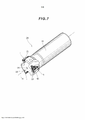
[0010] A Figura 7 é uma vista em perspectiva de uma ferramenta de corte sobre a qual o inserto de corte da Figura 1 está montado.[0010] Figure 7 is a perspective view of a cutting tool on which the cutting insert of Figure 1 is mounted.
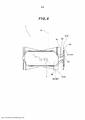
[0011] A Figura 8 é uma vista ampliada de um corpo de ferramenta da Figura 7.[0011] Figure 8 is an enlarged view of a tool body of Figure 7.
[0012] Uma modalidade da presente invenção será descrita a seguir com referência aos desenhos anexos. Um inserto de corte 1 de acordo com a presente modalidade é mostrado nas Figuras 1 a 6.[0012] An embodiment of the present invention will be described below with reference to the accompanying drawings. A
[0013] Conforme mostrado nas Figuras 1 a 4, o inserto de corte 1 inclui as superfícies de extremidade 2, 3 e uma superfície lateral periférica 4. As superfícies de extremidade 2, 3 incluem, respectivamente, em suas partes internas, partes planas 2a, 3a. As superfícies de extremidade 2, 3 são opostas entre si. Mais especificamente, as superfícies de extremidade 2, 3 são arranjadas de modo que a parte plana 2a e a parte plana 3a sejam paralelas entre si. A superfície lateral periférica 4 se estende de modo a conectar a superfície de extremidade 2 e a superfície de extremidade 3. No presente documento, a título de descrição, a superfície de extremidade 2 é chamada de “superfície superior 2”, e a superfície de extremidade 3 é chamada de uma “superfície inferior 3”. Além disso, uma direção na qual a superfície superior 2 e a superfície inferior 3 são opostas entre si é chamada de uma “direção de espessura”.[0013] As shown in Figures 1 to 4, the
[0014] Conforme mostrado na Figura 2, a superfície superior 2 tem um formato substancialmente triangular. O diâmetro do círculo inscrito do triângulo é de aproximadamente 10 mm. A superfície superior 2 inclui três bordas laterais e três cantos. No presente documento, o termo “borda lateral” se refere a, em uma superfície de extremidade, uma porção de borda da mesma que se estende entre os cantos. Mais especificamente, o termo “borda lateral” se refere a uma porção de uma borda da superfície superior que não é as partes curvas dos cantos. Uma borda de corte 5 está arranjada em cada canto e nas bordas laterais periféricas. Uma porção da superfície superior 2 que está conectada à borda de corte 5 funciona como uma superfície inclinada 7. Como mostrado na Figura 1, uma porção da superfície lateral periférica 4 que está conectada à borda de corte 5 funciona como um flanco 4a. Deve ser observado que o raio de curvatura do canto é de aproximadamente 0,8 mm.[0014] As shown in Figure 2, the
[0015] Conforme mostrado na Figura 3, a superfície inferior 3 tem um formato substancialmente triangular, de maneira similar à superfície superior 2. A superfície inferior 3 também inclui três bordas laterais e três cantos. Uma borda de corte 5 está arranjada em cada canto da superfície inferior 3 e das bordas laterais periféricas. Uma porção da superfície inferior 3 que está conectada à borda de corte 5 funciona como uma superfície inclinada 7. Uma porção da superfície lateral periférica 4 que está conectada à borda de corte 5 funciona como um flanco 4a.[0015] As shown in Figure 3, the
[0016] No inserto de corte 1, seis bordas de corte 5 são providas no total - três para a superfície superior 2 e três para a superfície inferior 3. Cada borda de corte 5 inclui uma borda de corte principal 6a, uma borda de corte de canto 6b e uma borda de corte menor 6c. A borda de corte principal 6a está arranjada em uma borda lateral e ocupa uma parte principal de uma borda lateral. Em outras palavras, no inserto de corte 1, uma parte principal de uma borda lateral pode ser usada como a borda de corte principal 6a. A borda de corte de canto 6b está arranjada em cada canto. A borda de corte menor 6c está arranjada no lado oposto à borda de corte principal 6a através da borda de corte de canto 6b. A borda de corte menor 6c está arranjada entre a borda de corte de canto 6b e a borda de corte principal 6a da borda de corte adjacente 5.[0016] On the cutting insert 1, six
[0017] Uma vez que as respectivas bordas de corte 5 incluem bordas de corte principais de formato diferente 6a e bordas de corte menores em formato diferente 6c, o inserto de corte 1 não tem simetria especular. Em outras palavras, a superfície superior 2 e a superfície inferior 3 não tem simetria especular entre si. Ou seja, conforme visto a partir de uma direção voltada para a superfície superior 2, quando um formato de contorno da superfície inferior 3 é projetada sobre a superfície superior 2, pelo menos parte do formato de contorno projetado da superfície inferior 3 não se sobrepõe a um formato de contorno da superfície superior 2. Tal porção que não envolve sobreposição é uma porção que corresponde principalmente à borda de corte menor 6c. O inserto de corte 1 é um inserto de corte de lado direito.[0017] Since the
[0018] Conforme mostrado na Figura 2, conforme visto a partir da direção voltada para a superfície superior 2, a borda de corte principal 6a é curvada de modo a protuberar para fora.[0018] As shown in Figure 2, as seen from the direction facing the
[0019] No presente documento, conforme mostrado nas Figuras 1 e 2, uma borda de corte 5 da superfície superior 2 é chamada de uma “primeira borda de corte 5a”. Além disso, conforme mostrado nas Figuras 1 e 3, uma borda de corte 5 da superfície inferior 3 é chamada de uma “segunda borda de corte 5b”. Mais especificamente, na vista plana da Figura 2, a borda de corte 5 arranjada no lado mais à direita é chamada de a “primeira borda de corte 5a”. Além disso, na vista inferior da Figura 3, a borda de corte 5 arranjada no lado mais alto é chamada de a “segunda borda de corte 5b”.[0019] In the present document, as shown in Figures 1 and 2, a
[0020] Conforme mostrado na Figura 4, quando o inserto de corte 1 é visto a partir de uma direção voltada para o flanco 4a, a primeira borda de corte 5a é curvada de modo a ser recuada para baixo. Em particular, a primeira borda de corte 5a é curvada de modo a criar inteiramente uma curva recuada uniformemente. Em contrapartida, a segunda borda de corte 5b é curvada de modo a ser recuada para cima.[0020] As shown in Figure 4, when the cutting
[0021] Conforme mostrado nas Figuras 1 a 3, o inserto de corte 1 é dotado de um furo de montagem 9 que penetra na superfície superior 2 e a superfície inferior 3. A superfície superior 2 tem simetria rotacional de 120 graus ao eixo geométrico central A do furo de montagem 9. De forma similar à superfície superior 2, a superfície inferior 3 tem simetria rotacional de 120 graus ao eixo geométrico central A do furo de montagem 9. O eixo geométrico central A do furo de montagem 9 é também chamado de um eixo geométrico de referência A do inserto de corte 1.[0021] As shown in Figures 1 to 3, the cutting
[0022] O inserto de corte 1 é análogo ao que se chama de um o que se chama de um inserto de corte de tipo negativo. Entretanto, na superfície lateral periférica 4 do inserto de corte 1, uma porção intermediária da mesma em uma direção de espessura se projeta para fora. Em outras palavras, conforme mostrado na Figura 1, a superfície lateral periférica 4 inclui uma porção de superfície lateral periférica intermediária 4b que está localizada mais para fora do que o flanco 4a.[0022] Cutting
[0023] No presente documento, um flanco 4a que está conectado à primeira borda de corte 5a da superfície superior 2 é chamado de um “primeiro flanco 4a1”, e um flanco 4a que está conectado à segunda borda de corte 5b da superfície inferior 3 é chamado de um “segundo flanco 4a2”.[0023] In the present document, a
[0024] A “porção de superfície lateral periférica intermediária 4b que se localiza mais para fora do que o flanco 4a” significa que, em uma vista plana, a porção de superfície lateral periférica intermediária 4b se localiza mais para fora do que o flanco 4a. Em outras palavras, conforme mostrado na Figura 5, quando o inserto de corte 1 é visto a partir da direção voltada para a superfície superior 2, a porção de superfície lateral periférica intermediária 4b está localizada mais para fora do que o primeiro flanco 4a1. Do mesmo modo, quando o inserto de corte 1 é visto a partir de uma direção voltada para a superfície inferior 3, a porção de superfície lateral periférica intermediária 4b está localizada mais para fora do que o segundo flanco 4a2 (não mostrado).[0024] The "intermediate peripheral
[0025] Na superfície lateral periférica 4, uma porção da mesma que está conectada à borda de corte principal 6a envolve uma pequena quantidade de protuberância para fora. No inserto de corte 1, a porção de superfície lateral periférica intermediária 4b está localizada mais para fora do que o flanco 4a, por toda a superfície lateral periférica 4.[0025] On the
[0026] O primeiro flanco 4a1 não recebe um ângulo de folga. Em outras palavras, o primeiro flanco 4a1 se estende em uma direção perpendicular à parte plana 3a da superfície inferior 3. A parte plana 2a da superfície superior 2 é paralela à parte plana 3a da superfície inferior 3. Portanto, o primeiro flanco 4a1 também se estende em uma direção perpendicular à parte plana 2a da superfície superior 2. Ou seja, um ângulo formado pelo primeiro flanco 4a1 e a parte plana 2a da superfície superior 2 é um ângulo reto. Do mesmo modo, o segundo flanco 4a2 se estende em uma direção perpendicular à superfície inferior 3. O flanco 4a se estende em uma direção perpendicular à parte plana 2a e à parte plana 3a, por toda a superfície lateral periférica 4.[0026] The first flank 4a1 does not receive a clearance angle. In other words, the first flank 4a1 extends in a direction perpendicular to the
[0027] Conforme mostrado na Figura 6, no que se refere a uma quantidade de protuberância da superfície lateral periférica intermediária 4b a partir do primeiro flanco 4a1, como denotado por B, a quantidade de protuberância B para a borda de corte principal 6a é de aproximadamente 0,5 mm. A quantidade de protuberância B para tanto a borda de corte de canto 6b quanto a borda de corte menor 6c tem um valor máximo de 2 mm.[0027] As shown in Figure 6, with regard to an amount of bulge of the intermediate
[0028] Na direção de espessura, uma distância da borda de corte 5a da superfície superior 2 até a borda de corte 5b da superfície inferior 3 tem um valor máximo de aproximadamente 6 mm. No presente documento, conforme mostrado na Figura 6, no que se refere a uma largura do primeiro flanco 4a1 na direção de espessura, conforme denotado por C, a largura C varia dependendo da posição. No primeiro flanco 4a1, a largura C de uma porção do mesmo que está conectada à borda de corte principal 6a tem um valor mínimo de 0,5 mm e um valor máximo de 2 mm; a largura C de uma porção do mesmo que está conectada à borda de corte de canto 6b tem um valor mínimo de 2 mm e um valor máximo de 3 mm; e a largura C de uma porção do mesmo que está conectada à borda de corte menor 6c tem um valor mínimo de 2 mm e um valor máximo de 3 mm.[0028] In the thickness direction, a distance from the cutting edge 5a of the
[0029] O formato da superfície inferior 3 é igual ao da superfície superior 2. Conforme mostrado nas Figuras 2 e 3, ao definir um eixo geométrico S de modo a ser ortogonal em relação ao eixo geométrico de referência A e penetrar a superfície lateral periférica 4, o inserto de corte 1 tem um formato de simetria rotacional de 180 graus em relação ao eixo geométrico S.[0029] The shape of the
[0030] Conforme descrito acima, o inserto de corte 1 inclui as três bordas de corte 5 no lado da superfície superior 2 e as três bordas de corte 5 no lado da superfície inferior 3. Todas as seis bordas de corte 5 têm o mesmo formato. Em outras palavras, o formato da segunda borda de corte 5b tem simetria rotacional de 180 graus com o formato da primeira borda de corte 5a. Portanto, o inserto de corte 1 é um inserto de corte com uso nos dois lados, significando que as seis bordas de corte 5 podem ser usadas para corte.[0030] As described above, cutting
[0031] Conforme descrito acima, a superfície superior 2 inclui a parte plana 2a, e a superfície inferior 3 inclui a parte plana 3a. A parte plana 2a e a parte plana 3a entram, cada uma, em contato com uma superfície de fundo 23 de uma peça de montagem de inserto 22 de um corpo de ferramenta 21 descrito abaixo. Conforme mostrado nas Figuras 2 e 3, a parte plana 2a e a parte plana 3a se estendem ao redor do furo de montagem 9. As bordas de corte 5 estão localizadas em um nível mais alto do que a parte plana 2a e a parte plana 3a. Em outras palavras, uma distância a partir de cada porção da primeira borda de corte 5a da superfície superior 2 até a superfície inferior 3 é mais longa do que uma distância a partir da parte plana 2a da superfície superior 2 até a superfície inferior 3. Do mesmo modo, uma distância a partir de cada porção da segunda borda de corte 5b da superfície inferior 3 até a superfície superior 2 é mais longa do que uma distância a partir da parte plana 3a da superfície inferior 3 até a superfície superior 2.[0031] As described above, the
[0032] A porção de superfície lateral periférica intermediária 4b do inserto de corte 1 entra em contato com uma superfície de parede da peça de montagem de inserto do corpo de ferramenta descrito abaixo.[0032] The intermediate peripheral
[0033] Os materiais usados para as bordas de corte 5 do inserto de corte 1 e suas áreas periféricas são materiais duros ou materiais obtidos pela aplicação de um revestimento, por CVD, PVD, etc., em materiais duros. Quanto a tais materiais duros, carboneto cimentado, cermet, cerâmica, um corpo sinterizado contendo nitreto de boro cúbico, um corpo sinterizado contendo diamante e diamante monocristalino podem ser usados. Os materiais para as porções que não sejam as bordas de corte 5 no inserto de corte 1 são, de preferência, os mesmos materiais duros como os descritos acima, etc.[0033] The materials used for the
[0034] A seguir, será feita uma descrição referente a uma ferramenta de corte 20 sobre a qual o inserto de corte 1 é montado, com referência às Figuras 7 e 8. A ferramenta de corte 20 inclui o inserto de corte 1 descrito acima e o corpo de ferramenta 21 tendo um formato substancialmente cilíndrico. Conforme mostrado na Figura 7, o inserto de corte 1 é montado sobre a peça de montagem de inserto 22 formada no corpo de ferramenta 21. O inserto de corte 1 é montado de forma removível por meio de um elemento de fixação que serve como um meio de montagem mecânica. A ferramenta de corte 20 inclui um parafuso de fixação 30 como um elemento de fixação. Deve-se observar que a ferramenta de corte 20 é adequada principalmente para a fresagem reta de rebordo.[0034] Next, a description will be made concerning a
[0035] O corpo de ferramenta 21 tem um eixo geométrico central D que se estende a partir de sua extremidade principal 26 para a sua extremidade de base. A extremidade principal 26 do corpo de ferramenta 21 é dotada de partes de montagem de inserto 22 para a montagem de insertos de corte 1. Um inserto de corte 1 pode ser montado de forma removível em cada peça de montagem de inserto 22. No corpo de ferramenta 21, três partes de montagem da inserção 22 estão arranjadas geralmente em distâncias iguais em uma direção circunferencial em torno do eixo geométrico central D. Entretanto, a presente invenção não é limitada à configuração acima, e um corpo de ferramenta pode ser dotado de partes de montagem de inserto, de modo que insertos de corte em vários formatos podem ser montados sobre o mesmo, partes de montagem de inserto podem não estar arranjadas a distâncias iguais e, adicionalmente, uma ferramenta de corte pode incluir um corpo de ferramenta que é dotado de uma única peça de montagem de inserto.[0035]
[0036] Conforme mostrado na Figura 8, a peça de montagem de inserto 22 inclui a superfície de fundo 23 e as superfícies de parede 24a, 24b, 24c. A superfície de fundo 23 e as superfícies de parede 24a, 24b, 24c são substancialmente planas. A superfície de fundo 23 é dotada de um furo rosqueado 25.[0036] As shown in Figure 8, the
[0037] As superfícies de parede 24a, 24b, 24c se estendem em uma direção substancialmente perpendicular à superfície de fundo 23. A superfície de parede 24a está arranjada de modo a ser direcionada para a extremidade de base do corpo de ferramenta 21, e as superfícies de parede 24b, 24c estão arranjadas de modo a serem orientadas em direção à extremidade principal 26 do corpo de ferramenta 21. A superfície de parede 24b e a superfície de parede 24c são arranjadas de modo a ficarem separadas uma da outra.[0037] The wall surfaces 24a, 24b, 24c extend in a direction substantially perpendicular to the
[0038] Quando o inserto de corte 1 está montado sobre a peça de montagem de inserto 22, a porção de superfície lateral periférica intermediária 4b da superfície lateral periférica 4 entra em contato com as superfícies de parede 24a, 24b, 24c e a parte plana 2a ou a parte plana 3a entra em contato com a superfície de fundo 23. O inserto de corte 1 é mantido entre a superfície de parede 24a e as superfícies de parede 24b, 24c.[0038] When the cutting
[0039] O furo rosqueado 25 se estende em uma direção perpendicular à superfície de fundo 23 e é aparafusado com o parafuso de fixação 30 acima descrito. Em outras palavras, a peça de montagem de inserto 22 tem um formato que é idêntico àquele de uma peça montagem de inserto sobre a qual é montado o que se chama de um inserto de corte de tipo negativo. Entretanto, a presente invenção não é limitada a tal configuração, e o formato da peça de montagem de inserto 22 pode ser qualquer formato, desde que a parte plana 2a ou 3a do inserto de corte 1 entre em contato com a superfície de fundo 23 e desde que o inserto de corte 1 possa ser fixado, e várias técnicas conhecidas são aplicáveis aqui.[0039] The threaded
[0040] O inserto de corte 1 é montado sobre a peça de montagem de inserto 22 de modo que uma das bordas de corte principais 6a esteja arranjada no lado periférico externo do corpo de ferramenta 21. Em mais detalhes, o inserto de corte 1 está montado sobre a peça de montagem de inserto 22 em uma posição na qual, ao girar a ferramenta de corte 20 em torno do eixo geométrico central D, uma trajetória rotacional da borda de corte principal 6a cria uma superfície cilíndrica que é geralmente paralela ao eixo geométrico central D. Assim, quando a ferramenta de corte 20 é vista a partir de uma direção voltada para a superfície de fundo 23 de uma peça de montagem de inserto 22, o inserto de corte 1 é montado de forma que a borda de corte principal 6a usada para corte fique substancialmente paralela ao eixo geométrico central D. Como resultado, a borda de corte simples 5 é usada para corte.[0040] Cutting
[0041] Além disso, a fim de impedir que a superfície lateral periférica 4 entre em contato com uma superfície de uma peça de trabalho, o inserto de corte 1 é montado de modo a estar inclinado para frente em uma direção de rotação da ferramenta de corte 20. Em outras palavras, o inserto de corte 1 é montado sobre a peça de montagem de inserto 22 de modo que, como no que se chama de inserto de corte de tipo negativo, ao flanco 4a é dado um ângulo de folga positivo apropriado. Deve ser observado que o mesmo se aplica à montagem do inserto de corte 1 no caso em que qualquer uma das outras cinco bordas de corte 5 seja usada para corte e, portanto, a sua descrição será omitida aqui.[0041] Furthermore, in order to prevent the
[0042] A seguir, será feita uma descrição com relação à operação e aos efeitos do inserto de corte 1 na presente modalidade e à ferramenta de corte 20 sobre a qual tal inserto de corte 1 é montado de forma removível. Uma descrição também será feita com relação às configurações preferenciais.[0042] In the following, a description will be made with respect to the operation and effects of the cutting
[0043] A ferramenta de corte 20 pode ser usada para cortar aço, etc., sendo fixada a uma ferramenta de usinagem tal como um centro de usinagem. A ferramenta de corte 20 é movida em relação a uma peça de trabalho enquanto é girada em torno do eixo geométrico central D. Isso permite que um corte como a fresagem reta de rebordo seja realizado.[0043] Cutting
[0044] A superfície lateral periférica 4 do inserto de corte 1 inclui a porção de superfície lateral periférica intermediária 4b que se projeta para fora. Tanto a borda de corte 5, que está localizada no lado oposto eixo geométrico à borda de corte 5 em uso para corte e que não está em uso para corte, quanto o flanco 4a estão cobertos pela porção de superfície lateral periférica intermediária 4b na direção de espessura. Assim, é possível suprimir o dano à borda de corte 5a que não está em uso para o corte e ao flanco 4a devido à colisão com o resíduo produzido durante o corte.[0044] The
[0045] Quando a quantidade de protuberância B da porção de superfície lateral periférica intermediária 4b do flanco 4a for menor do que 0,02 mm, o flanco 4a não é suficientemente coberto pela porção de superfície lateral periférica intermediária 4b. Como resultado, a área em torno da borda de corte 5 que não está em uso pode ser danificada. Além disso, se a quantidade de protuberância B for aumentada de modo a ficar acima de 3 mm, o efeito notável não pode ser obtido. Se a quantidade de protuberância B for excessivamente aumentada, haverá uma preocupação crescente de que a porção de superfície lateral periférica intermediária 4b entre em contato com uma peça de trabalho, durante a montagem do inserto de corte 1 na ferramenta de corte 20. Portanto, a quantidade de protuberância B é de preferência de 0,02 mm a 3 mm.[0045] When the amount of bulge B of the intermediate peripheral
[0046] A largura C do flanco 4a na direção de espessura é de preferência dez vezes ou mais do que a quantidade da protuberância B. Caso a largura C seja menor do que 0,2 mm, será difícil permitir que o flanco 4a funcione como um flanco. Além disso, um limite superior da largura C afeta a espessura do inserto de corte 1. Quando o flanco 4a é provido tanto no lado da superfície superior 2 quanto no lado da superfície inferior 3 de modo que a largura C exceda 4 mm e também quando a porção de superfície lateral periférica intermediária 4b é provida, o inserto de corte 1 se torna desnecessariamente espesso. Portanto, a largura C do flanco 4a na direção de espessura é de preferência entre 0,2 mm e 4 mm.[0046] The width C of the
[0047] Conforme descrito acima, esse inserto de corte 1 é um inserto de corte de lado direito. Em outras palavras, a superfície superior 2 e a superfície inferior 3 não constituem simetria especular. Caso tais superfície superior 2 e superfície inferior 3 tenham que ser conectadas por meio de uma superfície lateral periférica lisa, o inserto de corte teria uma forma diferente daquela do o que se chama de um inserto de corte de tipo negativo. Mais especificamente, em tal superfície lateral periférica, uma porção da mesma que é conectada à borda de corte menor 6c receberia um ângulo de folga negativo. Em tal caso, o ângulo de folga com relação somente ao inserto de corte pode variar de maneira complicada de acordo com a porção.[0047] As described above, this cutting
[0048] Em contrapartida, a superfície superior 2 e a superfície inferior 3 do inserto de corte 1 estão conectadas por meio da superfície lateral periférica 4 incluindo a porção de superfície lateral periférica intermediária 4b. A porção de superfície lateral periférica intermediária 4b se projeta a partir do flanco 4a. Assim, mesmo que a superfície superior 2 e a superfície inferior 3 não constituam simetria especular, o flanco 4a pode ter um ângulo de folga de zero, como no caso do que se chama de um inserto de corte de tipo negativo. Portanto, ao montar o inserto de corte 1 na ferramenta de corte 20, um ângulo de folga apropriado pode ser provido como no caso do que se chama de um inserto de corte de tipo negativo.[0048] In contrast, the
[0049] O formato da primeira borda de corte 5a sobre o lado da superfície superior 2 é o mesmo que o formato da segunda borda de corte 5b no lado da superfície inferior 3. Portanto, mudando a direção do inserto de corte 1, as posições das bordas de corte 5a, 5b são revertidas de modo que cada uma das bordas de corte 5a, 5b possa ser usada para corte. Entretanto, a presente invenção não é limitada a isso e também é aplicável a um inserto de corte que tenha bordas de corte de formatos diferentes entre o lado de superfície superior e o lado de superfície inferior. O efeito da presente invenção pode ser obtido, desde que uma porção de superfície lateral periférica intermediária se projete para fora a partir de um flanco que esteja conectado a uma borda de corte de pelo menos uma superfície de extremidade. Em outras palavras, a presente invenção é aplicável a um inserto de corte que é usado de uma maneira em que a área em torno de uma borda de corte que não esteja em uso está propensa a ser danificada.[0049] The shape of the first cutting edge 5a on the side of the
[0050] O inserto de corte 1 é o que se chama de um inserto de corte de tipo negativo. Em outras palavras, o primeiro flanco 4a1 e o segundo flanco 4a2 se estendem respectivamente em direções que são respectivamente perpendiculares à parte plana 2a da superfície superior 2 e à parte plana 3a da superfície inferior 3. Assim, no inserto de corte 1, não só a superfície superior 2 como também a superfície inferior 3 podem ser dotadas de bordas de corte 5, o que é econômico. Além disso, o uso do inserto de corte 1 é igual ao que se chama de um inserto de corte de tipo negativo. Em outras palavras, o inserto de corte 1 é fácil de usar. Só a característica na qual um ângulo de folga não é proporcionado em relação ao inserto de corte 1 já é vantajosa pelo fato de que, enquanto o dano à área em torno da borda de corte que não está em uso é suprimido, a porção de superfície lateral periférica intermediária 4b é impedida de entrar em contato com uma peça de trabalho. A razão para isto é que, se um ângulo de folga negativa for provido somente em relação ao inserto de corte 1, um ângulo de folga apropriado será provido quando o inserto de corte 1 for montado na ferramenta de corte, de modo que a superfície lateral periférica 4 fique bastante inclinada, por meio do que a protuberância da porção de superfície lateral periférica intermediária 4b terá relativamente menos probabilidade de fornecer o efeito. Por outro lado, caso seja for provido um ângulo de folga positivo somente em relação ao inserto de corte 1, a porção de superfície lateral periférica intermediária 4b terá uma relativa probabilidade de se projetar e, portanto, a parte de superfície lateral periférica intermediária 4b entrará facilmente em contato com uma peça de trabalho.[0050] Cutting
[0051] O inserto de corte 1 pode ser fabricado por métodos conhecidos. O inserto de corte 1 pode ser fabricado submetendo-se pó de metal, etc., a moldagem por pressão com o uso de um molde e, então, submetendo o produto resultante a sinterização, moagem, aplicação de um revestimento, etc. Deve-se observar, entretanto, que, com um molde para o que se chama de um inserto de corte negativo, é difícil obter, por meio de moldagem por pressão, uma parte principal do formato da superfície lateral periférica 4 na qual a parte intermediária se projeta, e, após a prensagem, é necessário dividir um molde de modo a retirar um corpo moldado de tal molde.[0051] Cutting
[0052] Quando a moldagem por pressão for realizada na direção de espessura utilizando-se um molde divisível (matriz), é vantajoso que, como na presente invenção, o primeiro flanco 4a1 próximo à borda de corte seja formado de modo a se estender na direção perpendicular à parte plana 2a da superfície superior 2 porque isso permite o ajuste de uma posição de moldagem servindo como uma das condições de moldagem. Se ao primeiro flanco 4a1 fosse dado um ângulo de folga positivo ou negativo, uma posição de moldagem na direção de espessura seria determinada pelo formato de um molde. Isso torna difícil permitir que o ajuste de uma posição de moldagem seja realizado. Em particular, quando tanto uma superfície superior quanto uma superfície inferior são dotadas de bordas de corte, o ajuste de uma posição de moldagem não pode ser realizado no lado de superfície inferior.[0052] When pressure molding is carried out in the thickness direction using a divisible mold (die), it is advantageous that, as in the present invention, the first flank 4a1 near the cutting edge is formed so as to extend in the direction perpendicular to the
[0053] Em contrapartida, no inserto de corte 1 da presente invenção, uma vez que a parte plana 2a da superfície superior 2 e o primeiro flanco 4a1 são ortogonais entre si, uma posição de moldagem na direção de espessura pode ser ajustada. Em outras palavras, o grau de liberdade para o ajuste das condições de moldagem é aumentado, de forma que a espessura entre a superfície superior 2 e a superfície inferior 3 no inserto de corte 1 pode ser ajustada com um alto grau de precisão. Deve-se notar que o molde pode ser dividido em dois na direção de espessura ou dividido em porções em uma direção lateral. No caso de dividir o molde na direção lateral, é preferível que o molde seja dividido em três. Entretanto, se o molde é dividido na direção lateral, é provável que o inserto de corte 1 envolva mais linhas divisórias nas bordas de corte 5 e, portanto, é mais preferível dividir o molde em dois na direção de espessura. No caso de divisão do molde na direção lateral, é preferível evitar a divisão do molde nas posições das bordas de corte 5 e dividir o molde nas posições das porções de conexão entre as bordas de corte 5.[0053] On the other hand, in the
[0054] Na ferramenta de corte 20 que permite a fresagem reta de rebordo, as aparas precisam ser descarregadas de modo a não danificarem uma superfície de parede que for usinada em uma peça de trabalho. Além disso, a resistência de corte precisa ser reduzida a fim de impedir a geração de trepidação. A fim de satisfazer tais requisitos, a ferramenta de corte 20 inclui o parafuso de fixação 30. Com o uso do parafuso de fixação 30, o inserto de corte 1 pode ser facilmente montado mesmo se sua parte plana 2a estiver localizada em um nível mais baixo do que a borda de corte 5, isto é, o inserto de corte 1 for formado de modo a ter o que se chama de uma borda de corte elevada. Além disso, as aparas podem ser descarregados facilmente, já que não há obstáculos, tais como cunhas ou peças pressionadoras, no lado da superfície inclinada 6.[0054] In the
[0055] Embora a modalidade da presente invenção tenha sido descrita acima, várias modificações podem ser feitas no inserto de corte e na ferramenta de corte da presente invenção. Por exemplo, o formato da superfície superior e da superfície inferior na modalidade acima descrita é um formato triangular, mas pode ser, em vez disso, um outro formato poligonal, tal como um formato quadrangular. Quando o formato da superfície superior do inserto de corte 1 for um formato triangular ou quadrangular, o inserto de corte pode ser projetado de modo a ser adequado para fresagem reta de rebordo, para a qual a descarga de aparas é importante. Nesse caso, o efeito de supressão de dano à área ao redor da borda de corte que não está em uso para corte é ainda mais aumentado.[0055] While the embodiment of the present invention has been described above, various modifications can be made to the cutting insert and cutting tool of the present invention. For example, the shape of the top surface and bottom surface in the above-described embodiment is a triangular shape, but may instead be another polygonal shape, such as a square shape. When the shape of the top surface of the cutting
[0056] A presente invenção não é limitada a uma ferramenta de corte rotativa substancialmente cilíndrica e é também aplicável a outras formas de ferramentas de corte, incluindo ferramentas de giro.[0056] The present invention is not limited to a substantially cylindrical rotary cutting tool and is also applicable to other forms of cutting tools, including turning tools.
[0057] Na modalidade acima descrita, a presente invenção foi descrita especificamente de uma determinada maneira, mas a presente invenção não é limitada à mesma. Deve ser reconhecido que várias alterações e mudanças podem ser feitas na presente invenção sem se afastar do espírito e escopo da invenção definida no escopo das reivindicações. Isto é, a presente invenção abrange todos os tipos de modificações, aplicações e equivalentes que são abrangidas pela ideia da presente invenção definida pelo escopo das reivindicações. Lista de Referências Numéricas[0057] In the above-described embodiment, the present invention has been specifically described in a certain manner, but the present invention is not limited thereto. It should be recognized that various alterations and changes may be made to the present invention without departing from the spirit and scope of the invention defined within the scope of the claims. That is, the present invention encompasses all types of modifications, applications and equivalents that are encompassed by the idea of the present invention defined by the scope of the claims. List of Numerical References
[0058] 1 Inserto de corte 2 Superfície superior (primeira superfície de extremidade) 2a Parte plana 3 Superfície inferior (segunda superfície de extremidade) 3a Parte plana 4 Superfície lateral periférica 4a Flanco 4a1 Primeiro flanco 4a2 Segundo flanco 4b Porção de superfície lateral periférica intermediária 5 Borda de corte 5a Primeira borda de corte 5b Segunda borda de corte 6a Borda de corte principal 6b Borda de corte de canto 6c Borda de corte menor 7 Superfície inclinada 9 Furo de montagem 20 Ferramenta de corte 21 Corpo de ferramenta 22 Parte de montagem de inserto 23 Superfície de fundo da parte de montagem de inserto 24a, 24b, 24c Superfície de parede da parte de montagem do inserto 25 Furo rosqueado 26 Terminação principal 30 Parafuso de fixação A Eixo geométrico de referência do inserto de corte (eixo geométrico central do furo de montagem) B Quantidade de protuberância da porção de superfície lateral periférica intermediária do primeiro flanco C Largura do primeiro flanco D Eixo geométrico central[0058] 1
Claims (6)
Applications Claiming Priority (3)
| Application Number | Priority Date | Filing Date | Title |
|---|---|---|---|
| JP2016-187701 | 2016-09-27 | ||
| JP2016187701 | 2016-09-27 | ||
| PCT/JP2016/088082 WO2018061227A1 (en) | 2016-09-27 | 2016-12-21 | Cutting insert and cutting tool |
Publications (2)
| Publication Number | Publication Date |
|---|---|
| BR112018004966A2 BR112018004966A2 (en) | 2018-10-02 |
| BR112018004966B1 true BR112018004966B1 (en) | 2022-03-15 |
Family
ID=59604781
Family Applications (1)
| Application Number | Title | Priority Date | Filing Date |
|---|---|---|---|
| BR112018004966-2A BR112018004966B1 (en) | 2016-09-27 | 2016-12-21 | CUTTING INSERT AND CUTTING TOOL |
Country Status (3)
| Country | Link |
|---|---|
| JP (1) | JP6179879B1 (en) |
| CN (1) | CN108136521B (en) |
| BR (1) | BR112018004966B1 (en) |
Families Citing this family (1)
| Publication number | Priority date | Publication date | Assignee | Title |
|---|---|---|---|---|
| JP6919824B2 (en) * | 2020-01-15 | 2021-08-18 | 株式会社タンガロイ | Cutting inserts and turning tools using the cutting inserts |
Family Cites Families (7)
| Publication number | Priority date | Publication date | Assignee | Title |
|---|---|---|---|---|
| SE525829C2 (en) * | 2002-06-26 | 2005-05-10 | Seco Tools Ab | Double sided inserts with bombed bisk cutting edge and manufacturing method for the insert |
| DE102008002486A1 (en) * | 2007-06-21 | 2008-12-24 | Ceramtec Ag | Negative insert with double positive clearance |
| DE102011107789B4 (en) * | 2011-07-18 | 2015-05-28 | Kennametal Inc. | Gear cutter cutting insert and gear cutter with such a gear cutter cutting insert |
| US8790049B2 (en) * | 2012-02-07 | 2014-07-29 | Iscar, Ltd. | Indexable double-negative cutting insert having protruding side abutment surfaces and cutting tool |
| US9925595B2 (en) * | 2012-09-27 | 2018-03-27 | Kyocera Corporation | Cutting insert and cutting tool |
| JP2014121772A (en) * | 2012-11-22 | 2014-07-03 | Mitsubishi Materials Corp | Cutting insert and cutting insert manufacturing method |
| EP3041632B1 (en) * | 2013-09-03 | 2023-06-07 | No Screw Ltd. | Mounting mechanism for a cutting insert, a cutting insert therefor and a cutting tool using said insert |
-
2016
- 2016-12-21 JP JP2017528593A patent/JP6179879B1/en active Active
- 2016-12-21 CN CN201680052177.3A patent/CN108136521B/en active Active
- 2016-12-21 BR BR112018004966-2A patent/BR112018004966B1/en active IP Right Grant
Also Published As
| Publication number | Publication date |
|---|---|
| JP6179879B1 (en) | 2017-08-16 |
| BR112018004966A2 (en) | 2018-10-02 |
| CN108136521B (en) | 2022-04-26 |
| CN108136521A (en) | 2018-06-08 |
| JPWO2018061227A1 (en) | 2018-09-27 |
Similar Documents
| Publication | Publication Date | Title |
|---|---|---|
| JP5988186B1 (en) | Cutting insert and cutting edge exchangeable rotary cutting tool | |
| US10239134B2 (en) | Tool body and cutting tool | |
| RU2519208C2 (en) | Insert and rotary cutting tool | |
| RU2648717C2 (en) | Rotary cutting tool and reversible cutting insert thereof | |
| KR102351870B1 (en) | Rotary cutting tool and reversible cutting insert having variable-width minor relief surfaces therefor | |
| US10343226B2 (en) | Cutting insert and cutting tool | |
| CN107000082B (en) | Cutting insert and cutting edge replaceable rotary cutting tool | |
| RU2677821C2 (en) | Double-sided indexable cutting insert and cutting tool therefor | |
| JP6119916B2 (en) | Cutting inserts and cutting tools | |
| JP6910293B2 (en) | Cutting inserts for turning tools and turning tools | |
| US10201855B2 (en) | Cutting insert, tool body and cutting tool | |
| US20170304911A1 (en) | Cutting insert having outwardly inclined side surface and inwardly inclined lower surface, and rotary cutting tool | |
| JP5991565B1 (en) | Cutting inserts, tool bodies and cutting tools | |
| CN107405699B (en) | Cutting insert and milling cutter | |
| JP4883430B2 (en) | Replaceable cutting tool | |
| WO2015137508A1 (en) | Cutting insert, tool body, and cutting tool | |
| BR112018004966B1 (en) | CUTTING INSERT AND CUTTING TOOL | |
| JP2016187836A (en) | Cutting insert and cutting edge replaceable cutting tool |
Legal Events
| Date | Code | Title | Description |
|---|---|---|---|
| B06U | Preliminary requirement: requests with searches performed by other patent offices: procedure suspended [chapter 6.21 patent gazette] | ||
| B07A | Application suspended after technical examination (opinion) [chapter 7.1 patent gazette] | ||
| B09A | Decision: intention to grant [chapter 9.1 patent gazette] | ||
| B16A | Patent or certificate of addition of invention granted [chapter 16.1 patent gazette] |
Free format text: PRAZO DE VALIDADE: 20 (VINTE) ANOS CONTADOS A PARTIR DE 21/12/2016, OBSERVADAS AS CONDICOES LEGAIS. |