BR112017027386B1 - MOORING MACHINE - Google Patents
MOORING MACHINE Download PDFInfo
- Publication number
- BR112017027386B1 BR112017027386B1 BR112017027386-1A BR112017027386A BR112017027386B1 BR 112017027386 B1 BR112017027386 B1 BR 112017027386B1 BR 112017027386 A BR112017027386 A BR 112017027386A BR 112017027386 B1 BR112017027386 B1 BR 112017027386B1
- Authority
- BR
- Brazil
- Prior art keywords
- wire
- unit
- rebar
- gripping member
- wires
- Prior art date
Links
- 238000005452 bending Methods 0.000 claims abstract description 100
- 230000033001 locomotion Effects 0.000 claims description 26
- 230000002452 interceptive effect Effects 0.000 claims description 3
- 230000007246 mechanism Effects 0.000 description 165
- 238000004804 winding Methods 0.000 description 35
- 230000000694 effects Effects 0.000 description 17
- 238000006073 displacement reaction Methods 0.000 description 14
- 230000004048 modification Effects 0.000 description 14
- 238000012986 modification Methods 0.000 description 14
- 230000002093 peripheral effect Effects 0.000 description 11
- 238000011144 upstream manufacturing Methods 0.000 description 10
- 230000005540 biological transmission Effects 0.000 description 9
- 238000003780 insertion Methods 0.000 description 8
- 230000037431 insertion Effects 0.000 description 8
- 238000009941 weaving Methods 0.000 description 8
- 238000000034 method Methods 0.000 description 6
- 238000010586 diagram Methods 0.000 description 5
- 230000000452 restraining effect Effects 0.000 description 4
- 230000008859 change Effects 0.000 description 2
- 238000012840 feeding operation Methods 0.000 description 2
- 239000000463 material Substances 0.000 description 2
- 230000009467 reduction Effects 0.000 description 2
- 230000003321 amplification Effects 0.000 description 1
- 230000008901 benefit Effects 0.000 description 1
- 230000033228 biological regulation Effects 0.000 description 1
- 238000009954 braiding Methods 0.000 description 1
- 239000003638 chemical reducing agent Substances 0.000 description 1
- 230000007423 decrease Effects 0.000 description 1
- 238000005265 energy consumption Methods 0.000 description 1
- 230000007257 malfunction Effects 0.000 description 1
- 239000002184 metal Substances 0.000 description 1
- 229910052751 metal Inorganic materials 0.000 description 1
- 238000003199 nucleic acid amplification method Methods 0.000 description 1
- 230000000149 penetrating effect Effects 0.000 description 1
Images


Classifications
-
- B—PERFORMING OPERATIONS; TRANSPORTING
- B21—MECHANICAL METAL-WORKING WITHOUT ESSENTIALLY REMOVING MATERIAL; PUNCHING METAL
- B21F—WORKING OR PROCESSING OF METAL WIRE
- B21F15/00—Connecting wire to wire or other metallic material or objects; Connecting parts by means of wire
- B21F15/02—Connecting wire to wire or other metallic material or objects; Connecting parts by means of wire wire with wire
- B21F15/06—Connecting wire to wire or other metallic material or objects; Connecting parts by means of wire wire with wire with additional connecting elements or material
-
- B—PERFORMING OPERATIONS; TRANSPORTING
- B21—MECHANICAL METAL-WORKING WITHOUT ESSENTIALLY REMOVING MATERIAL; PUNCHING METAL
- B21F—WORKING OR PROCESSING OF METAL WIRE
- B21F15/00—Connecting wire to wire or other metallic material or objects; Connecting parts by means of wire
- B21F15/02—Connecting wire to wire or other metallic material or objects; Connecting parts by means of wire wire with wire
- B21F15/04—Connecting wire to wire or other metallic material or objects; Connecting parts by means of wire wire with wire without additional connecting elements or material, e.g. by twisting
-
- B—PERFORMING OPERATIONS; TRANSPORTING
- B21—MECHANICAL METAL-WORKING WITHOUT ESSENTIALLY REMOVING MATERIAL; PUNCHING METAL
- B21F—WORKING OR PROCESSING OF METAL WIRE
- B21F7/00—Twisting wire; Twisting wire together
-
- B—PERFORMING OPERATIONS; TRANSPORTING
- B25—HAND TOOLS; PORTABLE POWER-DRIVEN TOOLS; MANIPULATORS
- B25B—TOOLS OR BENCH DEVICES NOT OTHERWISE PROVIDED FOR, FOR FASTENING, CONNECTING, DISENGAGING OR HOLDING
- B25B25/00—Implements for fastening, connecting or tensioning of wire or strip
-
- B—PERFORMING OPERATIONS; TRANSPORTING
- B65—CONVEYING; PACKING; STORING; HANDLING THIN OR FILAMENTARY MATERIAL
- B65B—MACHINES, APPARATUS OR DEVICES FOR, OR METHODS OF, PACKAGING ARTICLES OR MATERIALS; UNPACKING
- B65B13/00—Bundling articles
- B65B13/18—Details of, or auxiliary devices used in, bundling machines or bundling tools
- B65B13/24—Securing ends of binding material
- B65B13/28—Securing ends of binding material by twisting
- B65B13/285—Hand tools
-
- B—PERFORMING OPERATIONS; TRANSPORTING
- B65—CONVEYING; PACKING; STORING; HANDLING THIN OR FILAMENTARY MATERIAL
- B65B—MACHINES, APPARATUS OR DEVICES FOR, OR METHODS OF, PACKAGING ARTICLES OR MATERIALS; UNPACKING
- B65B27/00—Bundling particular articles presenting special problems using string, wire, or narrow tape or band; Baling fibrous material, e.g. peat, not otherwise provided for
- B65B27/10—Bundling rods, sticks, or like elongated objects
-
- E—FIXED CONSTRUCTIONS
- E04—BUILDING
- E04G—SCAFFOLDING; FORMS; SHUTTERING; BUILDING IMPLEMENTS OR AIDS, OR THEIR USE; HANDLING BUILDING MATERIALS ON THE SITE; REPAIRING, BREAKING-UP OR OTHER WORK ON EXISTING BUILDINGS
- E04G21/00—Preparing, conveying, or working-up building materials or building elements in situ; Other devices or measures for constructional work
- E04G21/12—Mounting of reinforcing inserts; Prestressing
- E04G21/122—Machines for joining reinforcing bars
- E04G21/123—Wire twisting tools
Landscapes
- Engineering & Computer Science (AREA)
- Mechanical Engineering (AREA)
- Architecture (AREA)
- Civil Engineering (AREA)
- Structural Engineering (AREA)
- Basic Packing Technique (AREA)
- Wire Processing (AREA)
- Hand Tools For Fitting Together And Separating, Or Other Hand Tools (AREA)
- Seal Device For Vehicle (AREA)
- Reinforcement Elements For Buildings (AREA)
Abstract
MÁQUINA DE AMARRAÇÃO. É provida uma máquina de amarração de varão para betão que permite que objetos de amarração, tais como varões para betão, sejam amarrados por arames com porções de extremidade dos arames direcionadas para o lado do objeto de amarração. A máquina de amarração de varão para betão (1A) inclui: um compartimento (2A) em que dois arames (W) são armazenados de maneira a serem retirados; uma unidade guia rotacional (5A) que enrola os arames justapostos (W) em torno dos varões para betão (S); uma unidade de alimentação de arame (3A) que enrola os arames (W) em torno dos varões para betão (S) com a unidade guia rotacional (5A) em uma operação de justaposição e alimentação dos arames (W) e enrola os arames (W), que são enrolados em torno dos varões para betão (S), em torno dos varões para betão (S); e uma unidade de amarração (7A) que entrelaça porções de cruzamento de um lado de extremidade e do outro lado de extremidade de cada um dos arames (W) enrolados em torno dos varões para betão (S). A unidade de amarração (7A) inclui uma porção de flexão (71) que dobra um lado de extremidade e o outro lado de extremidade (...).MOORING MACHINE. A concrete rod tying machine is provided which allows tying objects, such as concrete rods, to be tied by wires with end portions of the wires directed toward the side of the tying object. The concrete rod tying machine (1A) includes: a compartment (2A) in which two wires (W) are stored in order to be withdrawn; a rotational guide unit (5A) which wraps the juxtaposed wires (W) around the concrete bars (S); a wire feed unit (3A) which winds the wires (W) around the concrete bars (S) with the rotational guide unit (5A) in a juxtaposition and wire feed operation (W) and winds the wires ( W), which are wrapped around the concrete bars (S), around the concrete bars (S); and a tying unit (7A) which interweaves crossing portions of one end side and the other end side of each of the wires (W) wrapped around the concrete rods (S). The mooring unit (7A) includes a bending portion (71) that bends one end side and the other end side (...).
Description
[001] A presente invenção refere-se a uma máquina de amarração para amarração de um objeto de amarração, tal como vergalhões, com um arame.[001] The present invention relates to a tying machine for tying a tying object, such as rebar, with a wire.
[002] Na técnica relacionada, foi sugerida uma máquina de amarração denominada máquina de amarração de vergalhão que enrola um arame em torno de dois ou mais vergalhões e entrelaça o arame enrolado para amarrar os dois ou mais vergalhões.[002] In the related art, a tying machine called a rebar tying machine has been suggested which wraps a wire around two or more rebars and interweaves the wound wire to tie the two or more rebars together.
[003] Tal máquina de amarração de vergalhão convencional tem uma configuração em que um arame é alimentado e enrolado em torno de vergalhões e, então, é cortado, e uma porção, em que um lado de extremidade e o outro lado de extremidade do arame intersectam um ao outro, é entrelaçada para amarrar os vergalhões (por exemplo, ver Literatura de Patente 1).[003] Such a conventional rebar tying machine has a configuration in which a wire is fed and wound around rebars and then cut, and a portion, in which one end side and the other end side of the wire intersect each other, is interlaced to tie the rebars (for example, see Patent Literature 1).
[004] Na máquina de amarração de vergalhão convencional, o arame que amarra os vergalhões tem uma forma tal que uma extremidade e a outra extremidade do arame são direcionadas para o lado oposto aos vergalhões com relação aos vergalhões da porção em que os vergalhões são amarrados pelo arame. No entanto, no estado em que uma extremidade e a outra extremidade do arame após a amarração são direcionadas para o lado oposto aos vergalhões, o arame que amarra os vergalhões tem uma forma tal que porções de extremidade distais do arame são projetadas para serem maiores do que uma região entrelaçada do arame e, portanto, há um receio de interferir no trabalho.[004] In the conventional rebar tying machine, the wire that ties the rebars is shaped such that one end and the other end of the wire are directed away from the rebars with respect to the rebars of the portion where the rebars are tied by the wire. However, in the state where one end and the other end of the wire after tying are directed away from the rebars, the wire tying the rebars is shaped such that distal end portions of the wire are designed to be larger than than an intertwined region of the wire and, therefore, there is a fear of interfering with the work.
[005] Em contraste, uma técnica para dobrar uma extremidade distal de um arame em um lado do vergalhão sem que projetar a extremidade distal do arame é divulgada na Literatura de Patente 2.[005] In contrast, a technique for bending a distal end of a wire onto one side of the rebar without projecting the distal end of the wire is disclosed in Patent Literature 2.
[006] Uma técnica para dobrar uma extremidade de um arame em uma direção de entrelaçamento é divulgada na Literatura de Patente 3. LISTA DE CITAÇÃO LITERATURA DE PATENTE Literatura de Patente 1: Patente Japonesa N° 4747455 Literatura de Patente 2: Patente Japonesa N° 4570972 Literatura de Patente 3: Patente Japonesa N° 5674762[006] A technique for bending one end of a wire in a braiding direction is disclosed in
[007] No entanto, meios específicos relevantes para como e em que direção o arame é dobrado não são divulgados em nenhuma das Literaturas de Patente 2 e 3. Portanto, existe um receio de que, mesmo quando o arame é feito para ser dobrado de tal forma que as porções de extremidade do arame são localizadas mais próximo a uma parte de amarração do que o topo do arame, uma direção em que o arame é dobrado não seja fixada em uma direção desejada e o arame não possa ser dobrado de forma eficaz, de tal forma que as porções de extremidade do arame sejam direcionadas para o lado do vergalhão.[007] However, specific means relevant to how and in which direction the wire is bent are not disclosed in any of
[008] A presente invenção foi feita para solucionar tais problemas, e um objeto dela é prover uma máquina de amarração que é feita para dobrar de forma eficaz arames em uma direção desejada, de tal forma que porções de extremidade dos arames sejam localizadas mais próximo a objetos de amarração do que as porções de topo dos arames.[008] The present invention was made to solve such problems, and an object of it is to provide a tying machine that is made to efficiently bend wires in a desired direction, such that end portions of the wires are located closer to tying objects than the top portions of the wires.
[009] A fim de solucionar os problemas acima mencionados, a presente invenção provê uma máquina de amarração que inclui: uma unidade de alimentação que é capaz de enrolar arames em torno de objetos de amarração; uma unidade de preensão que prende os arames enrolados em torno dos objetos de amarração pela unidade de alimentação; e uma unidade de flexão que dobra os arames de tal forma que porções de extremidade dos arames presos pela unidade de preensão sejam localizadas mais próximo aos objetos de amarração do que porções de topo dos arames.[009] In order to solve the aforementioned problems, the present invention provides a tying machine that includes: a feeding unit that is capable of winding wires around tying objects; a gripping unit which secures the wires wrapped around the tying objects by the feed unit; and a bending unit which bends the wires such that end portions of the wires held by the gripping unit are located closer to the tying objects than top portions of the wires.
[010] Na presente invenção, é provida uma unidade de flexão para dobrar arames de forma tal que porções de extremidade dos arames presos por uma unidade de preensão sejam localizadas mais próximo a um objeto de amarração do que o topo do arame, e pelo que o arame pode ser dobrado de forma eficaz, de tal forma que as porções de extremidade do arame sejam localizadas mais próximo aos objetos de amarração do que o topo do arame.[010] In the present invention, a bending unit is provided for bending wires in such a way that end portions of the wires held by a gripping unit are located closer to a tying object than the top of the wire, and whereby the wire can be effectively bent such that the end portions of the wire are located closer to the tying objects than the top of the wire.
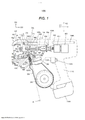
[011] A Figura 1 é uma vista de um exemplo de uma configuração global de uma máquina de amarração de vergalhão da presente modalidade conforme vista da parte lateral.[011] Figure 1 is a view of an example of an overall configuration of a rebar lashing machine of this embodiment as seen from the side.
[012] A Figura 2 é uma vista ilustrando um exemplo da configuração global da máquina de amarração de vergalhão da presente modalidade conforme vista da parte frontal.[012] Figure 2 is a view illustrating an example of the overall configuration of the rebar lashing machine of this embodiment as seen from the front.
[013] A Figura 3 é uma vista ilustrando um exemplo de um mecanismo de avanço de acordo com a presente modalidade.[013] Figure 3 is a view illustrating an example of an advance mechanism according to the present embodiment.
[014] A Figura 4A é uma vista ilustrando um exemplo de uma guia paralela da presente modalidade.[014] Figure 4A is a view illustrating an example of a parallel guide of the present embodiment.
[015] A Figura 4B é uma vista ilustrando um exemplo da guia paralela da presente modalidade.[015] Figure 4B is a view illustrating an example of the parallel guide of the present embodiment.
[016] A Figura 4C é uma vista ilustrando um exemplo da guia paralela da presente modalidade.[016] Figure 4C is a view illustrating an example of the parallel guide of the present embodiment.
[017] A Figura 4D é uma vista ilustrando um exemplo de arames paralelos.[017] Figure 4D is a view illustrating an example of parallel wires.
[018] A Figura 4E é uma vista ilustrando um exemplo de arames intersectados e entrelaçados.[018] Figure 4E is a view illustrating an example of intersecting and intertwined wires.
[019] A Figura 5 é uma vista ilustrando um exemplo de uma ranhura guia da presente modalidade.[019] Figure 5 is a view illustrating an example of a guide groove of the present embodiment.
[020] A Figura 6A é uma vista de partes principais de uma unidade de preensão da presente modalidade.[020] Figure 6A is a view of main parts of a gripping unit of the present embodiment.
[021] A Figura 6B é uma vista das partes principais da unidade de preensão da presente modalidade.[021] Figure 6B is a view of the main parts of the gripping unit of the present embodiment.
[022] A Figura 7 é uma vista explicativa de uma operação da máquina de amarração de vergalhão da presente modalidade.[022] Figure 7 is an explanatory view of an operation of the rebar lashing machine of the present embodiment.
[023] A Figura 8 é uma vista explicativa de uma operação da máquina de amarração de vergalhão da presente modalidade.[023] Figure 8 is an explanatory view of an operation of the rebar lashing machine of the present embodiment.
[024] A Figura 9 é uma vista explicativa de uma operação da máquina de amarração de vergalhão da presente modalidade.[024] Figure 9 is an explanatory view of an operation of the rebar lashing machine of the present embodiment.
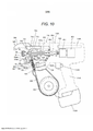
[025] A Figura 10 é uma vista explicativa de uma operação da máquina de amarração de vergalhão da presente modalidade.[025] Figure 10 is an explanatory view of an operation of the rebar lashing machine of the present embodiment.
[026] A Figura 11 é uma vista explicativa de uma operação da máquina de amarração de vergalhão da presente modalidade.[026] Figure 11 is an explanatory view of an operation of the rebar lashing machine of the present embodiment.
[027] A Figura 12 é uma vista explicativa de uma operação da máquina de amarração de vergalhão da presente modalidade.[027] Figure 12 is an explanatory view of an operation of the rebar lashing machine of the present embodiment.
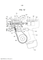
[028] A Figura 13 é uma vista explicativa de uma operação da máquina de amarração de vergalhão da presente modalidade.[028] Figure 13 is an explanatory view of an operation of the rebar lashing machine of the present embodiment.
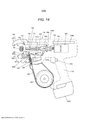
[029] A Figura 14 é uma vista explicativa de uma operação da máquina de amarração de vergalhão da presente modalidade.[029] Figure 14 is an explanatory view of an operation of the rebar lashing machine of the present embodiment.
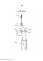
[030] A Figura 15A é uma vista explicativa de uma operação de enrolamento de um arame em torno de vergalhões.[030] Figure 15A is an explanatory view of a wire winding operation around rebar.
[031] A Figura 15B é uma vista explicativa de uma operação de enrolamento do arame em torno dos vergalhões.[031] Figure 15B is an explanatory view of a wire winding operation around the rebars.
[032] A Figura 15C é uma vista explicativa de uma operação de enrolamento do arame em torno dos vergalhões.[032] Figure 15C is an explanatory view of a wire winding operation around the rebars.
[033] A Figura 16A é uma vista explicativa de uma operação de flexão de um arame.[033] Figure 16A is an explanatory view of a wire bending operation.
[034] A Figura 16B é uma vista explicativa de uma operação de flexão do arame.[034] Figure 16B is an explanatory view of a wire bending operation.
[035] A Figura 16C é uma vista explicativa de uma operação de flexão do arame.[035] Figure 16C is an explanatory view of a wire bending operation.
[036] A Figura 17A é um exemplo de operação e efeitos da máquina de amarração de vergalhão da presente modalidade.[036] Figure 17A is an example of operation and effects of the rebar lashing machine of this embodiment.
[037] A Figura 17B é um exemplo de operação e problemas de uma máquina de amarração de vergalhão convencional.[037] Figure 17B is an example of operation and problems of a conventional rebar tying machine.
[038] A Figura 18A é um exemplo de operação e efeitos da máquina de amarração de vergalhão da presente modalidade.[038] Figure 18A is an example of operation and effects of the rebar lashing machine of this embodiment.
[039] A Figura 18B é um exemplo de operação e problemas da máquina de amarração de vergalhão convencional.[039] Figure 18B is an example of operation and problems of the conventional rebar tying machine.
[040] A Figura 19A é um exemplo de operação e efeitos da máquina de amarração de vergalhão da presente modalidade.[040] Figure 19A is an example of operation and effects of the rebar lashing machine of this modality.
[041] A Figura 19B é um exemplo de operação e problemas da máquina de amarração de vergalhão convencional.[041] Figure 19B is an example of operation and problems of the conventional rebar lashing machine.
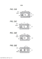
[042] A Figura 20A é um exemplo de operação e efeitos da máquina de amarração de vergalhão da presente modalidade.[042] Figure 20A is an example of operation and effects of the rebar lashing machine of this embodiment.
[043] A Figura 20B é um exemplo de operação e efeitos da máquina de amarração de vergalhão da presente modalidade.[043] Figure 20B is an example of operation and effects of the rebar lashing machine of this embodiment.
[044] A Figura 20C é um exemplo de operação e problemas da máquina de amarração de vergalhão convencional.[044] Figure 20C is an example of operation and problems of the conventional rebar lashing machine.
[045] A Figura 20D é um exemplo de operação e problemas da máquina de amarração de vergalhão convencional.[045] Figure 20D is an example of operation and problems of the conventional rebar lashing machine.
[046] A Figura 21A é um exemplo de operação e efeitos da máquina de amarração de vergalhão da presente modalidade.[046] Figure 21A is an example of operation and effects of the rebar lashing machine of this modality.
[047] A Figura 21B é um exemplo de operação e problemas da máquina de amarração de vergalhão convencional.[047] Figure 21B is an example of operation and problems of the conventional rebar lashing machine.
[048] A Figura 22A é uma vista explicativa ilustrando uma modificação da presente modalidade.[048] Figure 22A is an explanatory view illustrating a modification of the present embodiment.
[049] A Figura 22B é uma vista explicativa ilustrando uma modificação da presente modalidade.[049] Figure 22B is an explanatory view illustrating a modification of the present embodiment.
[050] A Figura 22C é uma vista explicativa ilustrando uma modificação da presente modalidade.[050] Figure 22C is an explanatory view illustrating a modification of the present embodiment.
[051] A Figura 23A é uma vista ilustrando uma modificação da guia paralela da presente modalidade.[051] Figure 23A is a view illustrating a modification of the parallel guide of the present embodiment.
[052] A Figura 23B é uma vista ilustrando uma modificação da guia paralela da presente modalidade.[052] Figure 23B is a view illustrating a modification of the parallel guide of the present embodiment.
[053] A Figura 23C é uma vista ilustrando uma modificação da guia paralela da presente modalidade.[053] Figure 23C is a view illustrating a modification of the parallel guide of the present embodiment.
[054] A Figura 23D é uma vista ilustrando uma modificação da guia paralela da presente modalidade.[054] Figure 23D is a view illustrating a modification of the parallel guide of the present embodiment.
[055] A Figura 23E é uma vista ilustrando uma modificação da guia paralela da presente modalidade.[055] Figure 23E is a view illustrating a modification of the parallel guide of the present embodiment.
[056] A Figura 24 é uma vista ilustrando uma modificação da ranhura guia da presente modalidade.[056] Figure 24 is a view illustrating a modification of the guide groove of the present embodiment.
[057] A Figura 25A é uma vista ilustrando uma modificação de uma unidade de alimentação de arame de acordo com a presente modalidade.[057] Figure 25A is a view illustrating a modification of a wire feed unit according to the present embodiment.
[058] A Figura 25B é uma vista ilustrando uma modificação da unidade de alimentação de arame de acordo com a presente modalidade.[058] Figure 25B is a view illustrating a modification of the wire feed unit according to the present embodiment.
[059] A Figura 26 é uma vista explicativa ilustrando uma configuração e uma operação da unidade de preensão de outra modalidade.[059] Figure 26 is an explanatory view illustrating a configuration and operation of the gripping unit of another embodiment.
[060] A Figura 27 é uma vista explicativa ilustrando uma configuração e uma operação da unidade de preensão de outra modalidade.[060] Figure 27 is an explanatory view illustrating a configuration and operation of the gripping unit of another embodiment.
[061] A Figura 28 é uma vista explicativa ilustrando uma configuração e uma operação da unidade de preensão de outra modalidade.[061] Figure 28 is an explanatory view illustrating a configuration and operation of the gripping unit of another embodiment.
[062] A Figura 29 é uma vista explicativa ilustrando uma configuração e uma operação da unidade de preensão de outra modalidade.[062] Figure 29 is an explanatory view illustrating a configuration and operation of the gripping unit of another embodiment.
[063] A Figura 30 é uma vista explicativa ilustrando uma configuração e uma operação da unidade de preensão de outra modalidade.[063] Figure 30 is an explanatory view illustrating a configuration and operation of the gripping unit of another embodiment.
[064] A Figura 31 é uma vista explicativa ilustrando uma configuração e uma operação da unidade de preensão de outra modalidade.[064] Figure 31 is an explanatory view illustrating a configuration and operation of the gripping unit of another embodiment.
[065] Doravante, um exemplo de uma máquina de amarração de vergalhão como uma modalidade de uma máquina de amarração da presente invenção será descrito com referência aos desenhos.[065] Hereinafter, an example of a rebar tying machine as an embodiment of a tying machine of the present invention will be described with reference to the drawings.
[066] A Figura 1 é uma vista de um exemplo da configuração global de uma máquina de amarração de vergalhão de acordo com a presente modalidade conforme vista de um lado, e a Figura 2 é uma vista ilustrando um exemplo da configuração global da máquina de amarração de vergalhão da presente modalidade conforme vista de uma parte frontal. Aqui, a Figura 2 esquematicamente ilustra a configuração interna da linha A-A na Figura 1.[066] Figure 1 is a view of an example of the global configuration of a rebar tying machine according to the present embodiment as seen from one side, and Figure 2 is a view illustrating an example of the global configuration of the rebar lashing machine rebar lashing of the present embodiment as seen from a front part. Here, Figure 2 schematically illustrates the internal configuration of the A-A line in Figure 1.
[067] Como ilustrado na Figura 1, a máquina de amarração de vergalhão 1A da presente modalidade é uma máquina de amarração portátil que pode ser transportada. A máquina de amarração de vergalhão 1A amarra vergalhões S, que são objetos de amarração, usando dois ou mais arames W tendo um pequeno diâmetro em comparação a um arame convencional tendo um grande diâmetro. Na máquina de amarração de vergalhão 1A, como será descrito abaixo, os vergalhões S são amarrados com os arames W por uma operação de enrolamento dos arames W em torno dos vergalhões S, uma operação de enrolamento dos arames W enrolados em torno dos vergalhões S para entrarem em contato próximo com os vergalhões S, uma operação de entrelaçamento dos arames enrolados em torno dos vergalhões S, e assim por diante. Na máquina de amarração de vergalhão 1A, uma vez que os arames W são dobrados por qualquer uma das operações descritas acima, os arames W tendo um diâmetro menor do que o arame convencional são usados. Assim, os arames podem ser enrolados em torno dos vergalhões S com pouca força, e os arames W pode ser entrelaçados com pouca força. Dois ou mais arames são usados e, assim, a resistência de amarração dos vergalhões S podem ser assegurada pelos arames W. Além disso, os dois ou mais arames W são configurados para serem dispostos e alimentados em paralelo e, assim, um tempo necessário para a operação de enrolamento dos arames W pode ser reduzido em comparação a uma operação de enrolamento dos vergalhões duas vezes ou mais com um arame. O enrolamento dos arames W em torno dos vergalhões S e o enrolamento dos arames W enrolados em torno dos vergalhões S para entrarem em contato próximo com os vergalhões S são coletivamente referidos como enrolamento dos arames W. Os arames W podem ser enrolados em torno de objetos de amarração que não os vergalhões S. Aqui, como os arames W, um arame simples ou um arame trançado formado de um metal que pode ser plasticamente deformado é usado.[067] As illustrated in Figure 1, the
[068] A máquina de amarração de vergalhão 1A inclui um compartimento 2A que é uma unidade de alojamento que aloja o arame W, uma unidade de alimentação de arame 3A que alimenta o arame W alojado no compartimento 2A, uma guia paralela 4A para dispor os arames W alimentados à unidade de alimentação de arame 3A e os arames W alimentados da unidade de alimentação de arame 3A em paralelo. A máquina de amarração de vergalhão 1A ainda inclui uma unidade guia rotacional 5A que enrola os arames W alimentados em paralelo em torno do vergalhão S, e uma unidade de corte 6A que corta o arame W enrolado em torno do vergalhão S. Além disso, a máquina de amarração de vergalhão 1A inclui uma unidade de amarração 7A que prende e entrelaça o arame W enrolado em torno do vergalhão S.[068] The
[069] O compartimento 2A é um exemplo de uma unidade de alojamento. Na modalidade, uma bobina 20 em que dois arames longos W são enrolados de maneira a serem retirados é alojada de forma removível. A bobina 20 é provida com uma porção de núcleo tubular 20a que pode enrolar os arames W e um par de flanges 20b que são providos em lados de extremidade opostos da porção de núcleo 20a em uma direção axial. Os flanges 20b têm um diâmetro maior do que a porção de núcleo 20a, e se projetam além dos lados de extremidade opostos da porção de núcleo 20a na direção axial. Dois ou mais arames W, neste exemplo, dois arames W são enrolados em torno da porção de núcleo 20a. Na máquina de amarração de vergalhão 1A, enquanto a bobina 20 alojada no compartimento 2A gira, os dois arames W são alimentados da bobina 20 através da operação de alimentação dos dois arames W pela unidade de alimentação de arame 3A e da operação de alimentação dos dois arames W manualmente. Neste momento, os dois arames W são enrolados em torno da porção de núcleo 24 de modo que os dois arames W são alimentados sem serem entrelaçados.[069]
[070] A unidade de alimentação de arame 3A é um exemplo de uma unidade de alimentação de arame constituindo uma unidade de alimentação e inclui um primeiro mecanismo de avanço 30L e um segundo mecanismo de avanço 30R como um par de membros de alimentação para alimentação dos arames paralelos W. O primeiro mecanismo de avanço 30L tem um formato de engrenagem cilíndrica que alimenta o arame W por uma operação de rotação, e o segundo mecanismo de avanço 30R também tem um formato de engrenagem cilíndrica que alterna o arame W com o primeiro mecanismo de avanço 30L. Embora os detalhes do primeiro mecanismo de avanço 30L e do segundo mecanismo de avanço 20 30R sejam descritos posteriormente, o primeiro mecanismo de avanço 30L e o segundo mecanismo de avanço 30R têm um formato de engrenagem cilíndrica em que dentes são formados na superfície periférica externa de um membro tipo disco. Apesar de o primeiro mecanismo de avanço 30L e o segundo mecanismo de avanço 30R são entrelaçados entre si, e a força de acionamento é transmitida de um mecanismo de avanço para o outro mecanismo de avanço, de modo que os dois arames W possam ser adequadamente alimentados, outros dispositivos de direção poderiam ser usados e o dispositivo não sendo necessariamente limitado a use de uma engrenagem cilíndrica.[070] The
[071] O primeiro mecanismo de avanço 30L e o segundo mecanismo de avanço 30R são, cada um, formados de um membro em formato de disco. Na unidade de alimentação de arame 3A, o primeiro mecanismo de avanço 30L e o segundo mecanismo de avanço 30R são providos de modo a alternar o percurso de alimentação do arame W, de modo que as superfícies periféricas externas do primeiro mecanismo de avanço 30L e do segundo mecanismo de avanço 30R sejam voltadas uma para a outra. O primeiro mecanismo de avanço 30L e o segundo mecanismo de avanço 30R alternam os dois arames paralelos W entre porções opostas à superfície periférica externa. O primeiro mecanismo de avanço 30L e o segundo mecanismo de avanço 30R alimentam dois arames W ao longo da direção de extensão do arame W em um estado em que os dois arames W são dispostos em paralelo entre si.[071] The
[072] A Figura 3 é uma vista de montagem ou operacional ilustrando um exemplo do mecanismo de avanço desta modalidade. A Figura 3 é uma vista seccional tomada ao longo da linha B-B da Figura 2. O primeiro mecanismo de avanço 30L inclui uma porção dentada 31L em sua superfície periférica externa. O segundo mecanismo de avanço 30R inclui uma porção dentada 31R em sua superfície periférica externa.[072] Figure 3 is an assembly or operational view illustrating an example of the advance mechanism of this modality. Figure 3 is a sectional view taken along line B-B of Figure 2. The
[073] O primeiro mecanismo de avanço 30L e o segundo mecanismo de avanço 30R são dispostos em paralelo entre si de modo que as porções dentadas 31L e 31R sejam voltadas uma para a outra. Em outras palavras, o primeiro mecanismo de avanço 30L e o segundo mecanismo de avanço 30R são dispostos em paralelo em uma direção ao longo da direção axial Ru1 de um laço Ru formado pelo arame W enrolado pela unidade guia rotacional 5A, ou seja, ao longo da direção axial do círculo virtual em que o laço Ru formado pelo arame W é considerado como um círculo. Na descrição a seguir, a direção axial Ru1 do laço Ru formado pelo arame W enrolado pela unidade guia rotacional 5A é também referida como a direção axial Ru1 do arame em laço W.[073] The
[074] O primeiro mecanismo de avanço 30L inclui uma primeira ranhura de alimentação 32L em sua superfície periférica externa. O segundo mecanismo de avanço 30R inclui uma segunda ranhura de alimentação 32R em sua superfície periférica externa. O primeiro mecanismo de avanço 30L e o segundo mecanismo de avanço 30R são dispostos de tal forma que a primeira ranhura de alimentação 32L e a segunda ranhura de alimentação 32R sejam voltadas uma para a outra e a primeira ranhura de alimentação 32L e a segunda ranhura de alimentação 32R formem uma porção de aperto.[074] The
[075] A primeira ranhura de alimentação 32L é formada em um formato de ranhura em V na superfície periférica externa do primeiro mecanismo de avanço 30L ao longo da direção de rotação do primeiro mecanismo de avanço 30L. A primeira ranhura de alimentação 32L tem uma primeira superfície inclinada 32La e uma segunda superfície inclinada 32Lb formando uma ranhura em V. A primeira ranhura de alimentação 32L tem uma seção transversal em V de modo que a primeira superfície inclinada 32La e a segunda superfície inclinada 32Lb sejam voltadas uma para a outra em um ângulo predeterminado. Quando os arames W são presos entre o primeiro mecanismo de avanço 30L e o segundo mecanismo de avanço 30R em paralelo, a primeira ranhura de alimentação 32L é configurada de tal forma que um arame entre os arames mais externos dos arames W dispostos em paralelo, neste exemplo, uma parte da superfície periférica externa de um arame W1 dos dois arames W dispostos em paralelo está em contato com a primeira superfície inclinada 32La e a segunda superfície inclinada 32Lb.[075] The
[076] A segunda ranhura de alimentação 32R é formada em um formato de ranhura em V na superfície periférica externa do segundo mecanismo de avanço 30R ao longo da direção de rotação do segundo mecanismo de avanço 30R. A segunda ranhura de alimentação 32R tem uma primeira superfície inclinada 32Ra e uma segunda superfície inclinada 32Rb que formam uma ranhura em V. Similar à primeira ranhura de alimentação 32L, a segunda ranhura de alimentação 32R tem um formato em corte transversal em V, e a primeira superfície inclinada 32Ra e a segunda superfície inclinada 32Rb são voltadas uma para a outra em um ângulo predeterminado. Quando o arame W é preso entre o primeiro mecanismo de avanço 30L e o segundo mecanismo de avanço 30R em paralelo, a segunda ranhura de alimentação 32R é configurada de tal forma que o outro arame entre os arames mais externos dos arames W dispostos em paralelo, neste exemplo, uma parte da superfície periférica externa do outro arame W2 dos dois arames W dispostos em paralelo está em contato com a primeira superfície inclinada 32Ra e com a segunda superfície inclinada 32Rb.[076] The
[077] Quando o arame W é apertado entre o primeiro mecanismo de avanço 30L e o segundo mecanismo de avanço 30R, a primeira ranhura de alimentação 32L é configurada com uma profundidade e um ângulo (entre a primeira superfície inclinada 32La e a segunda superfície inclinada 32Lb), de tal forma que uma parte, no lado faceando o segundo mecanismo de avanço 30R, de um arame W1 em contato com a primeira superfície inclinada 32La e a segunda superfície inclinada 32Lb se projeta do círculo inferior dentado 31La do primeiro mecanismo de avanço 30L.[077] When the wire W is clamped between the
[078] Quando o arame W é apertado entre o primeiro mecanismo de avanço 30L e o segundo mecanismo de avanço 30R, a segunda ranhura de alimentação 32R é configurada com uma profundidade e um ângulo (entre a primeira superfície inclinada 32Ra e a segunda superfície inclinada 32Rb), de tal forma que uma parte, no lado faceando o primeiro mecanismo de avanço 30L, do outro arame W2 em contato com a primeira superfície inclinada 32Ra e a segunda superfície inclinada 32Rb se projeta do círculo inferior dentado 31Ra do segundo mecanismo de avanço 30R.[078] When the wire W is clamped between the
[079] Como resultado, os dois arames W apertados entre o primeiro mecanismo de avanço 30L e o segundo mecanismo de avanço 30R são dispostos de tal forma que um arame W1 é comprimido contra a primeira superfície inclinada 32La e a segunda superfície inclinada 32Lb da primeira ranhura de alimentação 32L, e o outro arame W2 é comprimido contra a primeira superfície inclinada 32Ra e a segunda superfície inclinada 32Rb da segunda ranhura de alimentação 32R. Então, um arame W1 e o outro arame W2 são comprimidos um contra o outro. Portanto, por rotação do primeiro mecanismo de avanço 30L e do segundo mecanismo de avanço 30R, os dois arames W (um arame W1 e o outro arame W2) são simultaneamente alimentados entre o primeiro mecanismo de avanço 30L e o segundo mecanismo de avanço 30R estando, ao mesmo tempo, em contato entre si. Neste exemplo, a primeira ranhura de alimentação 32L e a segunda ranhura de alimentação 32R têm um formato em corte transversal em V, mas não necessariamente limitado ao formato de ranhura em V, e pode ser, por exemplo, um formato trapezoidal ou um formato arqueado. Além disso, a fim de transmitir a rotação do primeiro mecanismo de avanço 30L ao segundo mecanismo de avanço 30R, entre o primeiro mecanismo de avanço 30L e o segundo mecanismo de avanço 30R, um mecanismo de transmissão incluindo um número par de engrenagens ou semelhantes para girar o primeiro mecanismo de avanço 30L e o segundo mecanismo de avanço 30R em direções opostas entre si pode ser provido.[079] As a result, the two wires W clamped between the
[080] A unidade de alimentação de arame 3A inclui uma unidade de acionamento 33 para acionar o primeiro mecanismo de avanço 30L e uma unidade de deslocamento 34 para comprimir e separar o segundo mecanismo de avanço 30R em relação ao primeiro mecanismo de avanço 30L.[080] The
[081] A unidade de acionamento 33 inclui um motor de alimentação 33a para acionar o primeiro mecanismo de avanço 30L e um mecanismo de transmissão 33b incluindo uma combinação de uma engrenagem e semelhantes para transmitir a força de acionamento do motor de alimentação 33a ao primeiro mecanismo de avanço 30L.[081] The
[082] No primeiro mecanismo de avanço 30L, a operação de rotação do motor de alimentação 33a é transmitida através do mecanismo de transmissão 33b e o primeiro mecanismo de avanço 30L gira. No segundo mecanismo de avanço 30R, a operação de rotação do primeiro mecanismo de avanço 30L é transmitida à porção dentada 31R através da porção dentada 31L e o segundo mecanismo de avanço 30R gira de acordo com o primeiro mecanismo de avanço 30L.[082] In the
[083] Como resultado, pela rotação do primeiro mecanismo de avanço 30L e do segundo mecanismo de avanço 30R, devido à força de atrito gerada entre o primeiro mecanismo de avanço 30L e o arame W1, a força de atrito gerada entre o segundo mecanismo de avanço 30R e o outro arame W2, e a força de atrito gerada entre o arame W1 e o outro arame W2, os dois arames W são alimentados em um estado de serem dispostos em paralelo entre si.[083] As a result, by rotating the
[084] Por comutação das direções para frente e para trás da direção de rotação do motor de alimentação 33a, a unidade de alimentação de arame 3A comuta a direção de rotação do primeiro mecanismo de avanço 30L e a direção de rotação do segundo mecanismo de avanço 30R, e a direção para frente e para trás da direção de alimentação do arame W são comutadas.[084] By switching the forward and backward directions of the rotation direction of the feed motor 33a, the
[085] Na máquina de amarração de vergalhão 1A, por rotação para frente do primeiro mecanismo de avanço 30L e do segundo mecanismo de avanço 30R na unidade de alimentação de arame 3A, o arame W é alimentado na direção para frente indicada pela seta X1, ou seja, na direção da unidade guia rotacional 5A e é enrolado em torno do vergalhão S na unidade guia rotacional 5A. Além disso, após o arame W ser enrolado em torno do vergalhão S, o primeiro mecanismo de avanço 30L e o segundo mecanismo de avanço 30R são girados ao contrário, pelo que o arame W é alimentado na direção posterior indicada pela seta X2, ou seja, na direção do compartimento 2A (puxado para trás). O arame W é enrolado em torno do vergalhão S e, então, puxado para trás, pelo que o arame W é colocado em contato próximo com o vergalhão S.[085] On the
[086] A unidade de deslocamento 34 inclui um primeiro membro de deslocamento 35 que desloca o segundo mecanismo de avanço 30R em uma direção em que o segundo mecanismo de avanço 30R é colocado em contato próximo e separado com/do primeiro mecanismo de avanço 30L na operação de rotação com o eixo 34a como um fulcro e um segundo membro de deslocamento 36 que desloca o primeiro membro de deslocamento. O segundo mecanismo de avanço 30R é comprimido na direção do primeiro mecanismo de avanço 30L por uma mola, não mostrada, que inclina o segundo membro de deslocamento 36. Dessa forma, neste exemplo, os dois arames W são presos entre a primeira ranhura de alimentação 32L do primeiro mecanismo de avanço 30L e a segunda ranhura de alimentação 32R do segundo mecanismo de avanço 30R. Além disso, a porção dentada 31L do primeiro mecanismo de avanço 30L e a porção dentada 31R do segundo mecanismo de avanço 30R se entrelaçam uma com a outra. Aqui, na relação entre o primeiro membro de deslocamento 35 e o segundo membro de deslocamento 36, pelo deslocamento do segundo membro de deslocamento 36 para colocar o primeiro membro de deslocamento 35 em um estado livre, o segundo mecanismo de avanço 30R pode ser separado do primeiro mecanismo de avanço 30L. No entanto, o primeiro membro de deslocamento 35 e o segundo membro de deslocamento 36 podem ser interligados um com o outro.[086] The
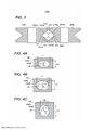
[087] As Figuras 4A, 4B e 4C são vistas ilustrando um exemplo da guia paralela de acordo com a presente modalidade. Aqui, as Figuras 4A, 4B e 4C são vistas em seção transversal tomadas ao longo da linha C-C da Figura 2 e mostram o formato seccional transversal da guia paralela 4A provida na posição de introdução P1. Além disso, a vista em seção transversal tomada ao longo de uma linha D-D da Figura 2 ilustrando o formato seccional da guia paralela 4A provida na posição intermediária P2, e a vista em seção transversal tomada ao longo de uma linha E-E da Figura 2 ilustrando o formato seccional da guia paralela 4A provida na posição de descarga de corte P3 mostram o mesmo formato. Além disso, a Figura 4D é uma vista ilustrando um exemplo de arames paralelos, e a Figura 4E é uma vista ilustrando um exemplo de arames entrelaçados intersectando um ao outro.[087] Figures 4A, 4B and 4C are views illustrating an example of the parallel guide according to the present embodiment. Here, Figures 4A, 4B and 4C are cross-sectional views taken along the line C-C of Figure 2 and show the cross-sectional shape of the
[088] A guia paralela 4A é um exemplo de uma unidade de restrição constituindo a unidade de alimentação e restringe a direção de uma pluralidade de (dois ou mais) arames W que foram enviados. Dois ou mais arames W entram e a guia paralela 4A alimenta os dois ou mais arames W em paralelo. Na guia paralela 4A, dois ou mais arames são dispostos em paralelo ao longo de uma direção ortogonal à direção de alimentação do arame W. Especificamente, dois ou mais arames W são dispostos em paralelo ao longo da direção axial do arame em laço W enrolado em torno do vergalhão S pela unidade guia rotacional 5A. A guia paralela 4A tem uma unidade de restrição de arame (por exemplo, uma abertura 4AW descrita posteriormente) que restringe as direções dos dois ou mais arames W e os torna paralelos. Neste exemplo, a guia paralela 4A tem um corpo guia principal 4AG, e o corpo guia principal 4AG é formado com uma abertura 4AW que é a unidade de restrição de arame para passar (inserir) uma pluralidade de arames W. A abertura 4AW penetra no corpo guia principal 4AG ao longo da direção de alimentação do arame W. Quando a pluralidade de arames enviados W passa através da abertura 4AW e após passar através da abertura 4AW, a sua configuração ou posicionamento relativo é determinado de modo que a pluralidade de arames W seja disposta em paralelo (cada um da pluralidade de arames W é alinhado adjacentes um ao outro em uma direção (direção radial) ortogonal à direção de alimentação do arame W (direção axial) e o eixo de cada um da pluralidade de arames W é substancialmente paralelo um ao outro na direção de alimentação). Portanto, a pluralidade de arames W que passou através da guia paralela 4A sai da guia paralela 4A em um estado de serem dispostos em paralelo. Desta forma, a guia paralela 4A restringe o movimento dos arames e o movimento relativo dos arames na direção radial (restringindo movimento nas direções ortogonais para a direção de alimentação) de modo que os dois arames W sejam dispostos em paralelo. Portanto, na abertura 4AW, uma direção ortogonal à direção de alimentação do arame W é maior do que a outra direção que é ortogonal à direção de alimentação do arame W ortogonal à direção. A abertura 4AW tem uma direção longitudinal (em que dois ou mais arames W podem ser justapostos) e é disposta ao longo de uma direção ortogonal à direção de alimentação do arame W, mais especificamente, ao longo da direção axial do arame W em laço pela unidade guia rotacional 5A. Como resultado, dois ou mais arames W inseridos através da abertura 4AW são alimentados em paralelo a cada um na direção de alimentação, com movimento relativo restrito. Além disso, o arame é deslocado relativamente ao outro arame em uma direção ortogonal à direção de alimentação do arame W, e no exemplo preferido, eixos dos arames são deslocados na direção axial Ru1 do arame em laço W.[088] The
[089] Na descrição a seguir, ao descrever o formato da abertura 4AW, um formato em seção transversal em uma direção ortogonal à direção de alimentação do arame W será descrito. O formato em seção transversal na direção ao longo da direção de alimentação do arame W será descrito em cada caso.[089] In the following description, when describing the shape of the 4AW aperture, a cross-sectional shape in a direction orthogonal to the W wire feed direction will be described. The cross-sectional shape in the direction along the wire feed direction W will be described in each case.
[090] Por exemplo, quando a abertura 4AW (a sua seção transversal) é um círculo tendo um diâmetro igual ou maior do que duas vezes o diâmetro do arame W, ou o comprimento de um lado é substancialmente um quadrado que é duas vezes ou mais o diâmetro do arame W, os dois arames W passando através da abertura 4AW estão em um estado em que podem se mover livremente na direção radial.[090] For example, when the aperture 4AW (its cross section) is a circle having a diameter equal to or greater than twice the wire diameter W, or the length of one side is substantially a square that is twice or plus the wire diameter W, the two wires W passing through aperture 4AW are in a state where they can move freely in the radial direction.
[091] Se os dois arames W passando através da abertura 4AW puderem se mover livremente na direção radial dentro da abertura 4AW, a direção em que os dois arames W são dispostos na direção radial não pode ser restrita, pelo que os dois arames W que saem da abertura 4AW não poderiam estar em paralelo, poderiam ser entrelaçados ou intersectados ou interferir um com o outro.[091] If the two W wires passing through the 4AW aperture can move freely in the radial direction within the 4AW aperture, the direction in which the two W wires are arranged in the radial direction cannot be restricted, whereby the two W wires that output from the 4AW aperture could not be parallel, could be intertwined or intersected or interfere with each other.
[092] Em vista disso, a abertura 4AW é formada de maneira que o comprimento na direção ou dimensão, ou seja, o comprimento L1 na direção longitudinal seja configurado para ser ligeiramente (n) vezes maior do que o diâmetro r do arame W na forma em que a pluralidade (n) de arames W são dispostos ao longo da direção radial, e o comprimento na outra direção, ou seja, o comprimento L2 na direção lateral seja configurado para ser ligeiramente (n) vezes maior do que o diâmetro r de um arame W. No presente exemplo, a abertura 4AW tem um comprimento L1 na direção longitudinal ligeiramente duas vezes maior do que um diâmetro r dos arames W, e um comprimento L2 na direção lateral ligeiramente mais longo do que um diâmetro r de um arame W. Na presente modalidade, a guia paralela 4A é configurada, de tal forma que a direção longitudinal da abertura 4AW é linear e a direção lateral é arqueada, mas a configuração não é assim limitada.[092] In view of this, the 4AW opening is formed so that the length in the direction or dimension, that is, the length L1 in the longitudinal direction is configured to be slightly (n) times greater than the diameter r of the wire W in the way in which the plurality (n) of wires W are arranged along the radial direction, and the length in the other direction, i.e. the length L2 in the lateral direction is configured to be slightly (n) times greater than the diameter r of a wire W. In the present example, the aperture 4AW has a length L1 in the longitudinal direction slightly longer than a diameter r of the wires W, and a length L2 in the lateral direction slightly longer than a diameter r of a wire W. W. In the present embodiment, the
[093] No exemplo ilustrado na Figura 4A, o comprimento L2 na direção lateral (ou direção de menor largura) da guia paralela 4A é configurado para um comprimento ligeiramente mais longo do que o diâmetro r de um arame W como um comprimento preferível. No entanto, uma vez que é suficiente que o arame W saia da abertura 4AW em um estado paralelo sem intersecção ou sem ser entrelaçado, na configuração em que a direção longitudinal (L1 ou direção de maior largura) da guia paralela 4A é orientada ao longo da direção axial Ru1 do laço do arame W enrolado em torno do vergalhão S na unidade guia rotacional 5A, o comprimento L2 da guia paralela 4A na direção lateral, como ilustrado na Figura 4B, pode estar dentro de uma faixa de um comprimento ligeiramente mais longo do que o diâmetro r de um arame W para um comprimento ligeiramente mais curto do que o diâmetro r de dois arames W.[093] In the example illustrated in Figure 4A, the length L2 in the lateral direction (or direction of smaller width) of the
[094] Além disso, na configuração em que a direção longitudinal da guia paralela 4A é orientada em uma direção ortogonal à direção axial Ru1 do laço do arame W enrolado em torno do vergalhão S na unidade guia rotacional 5A, como ilustrado na Figura 4C, o comprimento L2 na direção lateral da guia paralela 4A pode estar dentro de uma faixa de um comprimento ligeiramente mais longo do que o diâmetro r de um arame W para um comprimento mais curto do que o diâmetro r de dois arames W.[094] Furthermore, in the configuration in which the longitudinal direction of the
[095] Na guia paralela 4A, a direção longitudinal da abertura 4AW é orientada ao longo de uma direção ortogonal à direção de alimentação do arame W, neste exemplo, ao longo da direção axial Ru1 do laço formado pelo arame W enrolado em torno do vergalhão S na unidade guia rotacional 5A.[095] In the
[096] Como resultado, a guia paralela 4A pode passar dois arames em paralelo ao longo da direção axial Ru1 do laço formado pelo arame W.[096] As a result, the
[097] Na guia paralela 4A, quando o comprimento L2 na direção lateral da abertura 4AW é mais curto do que duas vezes o diâmetro r do arame W e ligeiramente mais longo do que o diâmetro r do arame W, mesmo se o comprimento L1 na direção longitudinal da abertura 4AW for suficientemente duas vezes ou mais vezes maior do que o diâmetro r de arame W, é possível alimentar os arames W em paralelo.[097] In the
[098] No entanto, quanto maior o comprimento L2 na direção lateral (por exemplo, o comprimento próximo a duas vezes o diâmetro r do arame W) e quanto maior o comprimento L1 na direção longitudinal, o arame W pode ainda se mover livremente na abertura 4AW. Então, os respectivos eixos dos dois arames W não se tornam paralelos na abertura 4AW, e existe uma alta possibilidade de os arames W serem entrelaçados ou intersectarem (interferirem) um ao outro após passarem através da abertura 4AW.[098] However, the greater the length L2 in the lateral direction (for example, the length close to twice the diameter r of the wire W) and the greater the length L1 in the longitudinal direction, the wire W can still move freely in the 4AW aperture. So, the respective axes of the two W wires do not become parallel in the 4AW aperture, and there is a high possibility that the W wires will be tangled or intersect (interfere) with each other after passing through the 4AW aperture.
[099] Portanto, é preferível que o comprimento longitudinal L1 da abertura 4AW seja ligeiramente mais longo do que duas vezes o diâmetro r do arame W, e o comprimento L2 na direção lateral seja também ligeiramente mais longo do que o diâmetro r do arame W de modo que os dois arames W sejam dispostos em paralelo na direção de alimentação e movimento relativo dos dois arames é liminado nas direções ortogonais à direção de alimentação ao longo da direção radial do arame.[099] Therefore, it is preferable that the longitudinal length L1 of the opening 4AW is slightly longer than twice the diameter r of the wire W, and the length L2 in the lateral direction is also slightly longer than the diameter r of the wire W so that the two wires W are arranged parallel in the feed direction and relative movement of the two wires is limited in directions orthogonal to the feed direction along the radial direction of the wire.
[0100] A guia paralela 4A é provida em posições predeterminadas no lado a montante e no lado a jusante do primeiro mecanismo de avanço 30L e do segundo mecanismo de avanço 30R (a unidade de alimentação de arame 3A) em relação à direção de alimentação para alimentação do arame W na direção para frente. Ao prover a guia paralela 4A no lado a montante do primeiro mecanismo de avanço 30L e do segundo mecanismo de avanço 30R, os dois arames W em um estado paralelo entram na unidade de alimentação de arame 3A. Portanto, a unidade de alimentação de arame 3A pode alimentar o arame W adequadamente (em paralelo). Além disso, ao prover a guia paralela 4A também no lado a jusante do primeiro mecanismo de avanço 30L e do segundo mecanismo de avanço 30R, mantendo ao mesmo tempo o estado paralelo dos dois arames W enviados da unidade de alimentação de arame 3A, o arame W pode ser ainda enviado para o lado a jusante.[0100] The
[0101] As guias paralelas 4A providas no lado a montante do primeiro mecanismo de avanço 30L e do segundo mecanismo de avanço 30R são providas na posição de introdução P1 entre o primeiro mecanismo de avanço 30L e o segundo mecanismo de avanço 30R e o compartimento 2A, de tal forma que os arames W alimentados à unidade de alimentação de arame 3A sejam dispostos em paralelo em uma direção predeterminada.[0101] The parallel guides 4A provided on the upstream side of the
[0102] Uma das guias paralelas 4A provida no lado a jusante do primeiro mecanismo de avanço 30L e do segundo mecanismo de avanço 30R é provida na posição intermediária P2 entre o primeiro mecanismo de avanço 30L e o segundo mecanismo de avanço 30R e a unidade de corte 6A, de tal forma que os arames W alimentados à unidade de corte 6A são dispostos em paralelo na direção predeterminada.[0102] One of the
[0103] Além disso, a outra das guias paralelas 4A provida no lado a jusante do primeiro mecanismo de avanço 30L e do segundo mecanismo de avanço 30R é provida na posição de descarga de corte P3 em que a unidade de corte 6A é disposta, de tal forma que os arames W alimentados à unidade guia rotacional 5A são dispostos em paralelo na direção predeterminada.[0103] In addition, the other of the
[0104] A guia paralela 4A provida na posição de introdução P1 tem o formato acima descrito em que pelo menos o lado a jusante da abertura 4AW restringe a direção radial do arame W em relação à direção de alimentação do arame W enviado na direção para frente. Por outro lado, a área de abertura do lado faceando o compartimento 2A (a unidade de introdução de arame), que é o lado a montante da abertura 4AW em relação à direção de alimentação do arame W enviado na direção para frente, tem uma maior área de abertura do que o lado a jusante. Especificamente, a abertura 4AW tem uma porção de orifício em formato de tubo que restringe a direção do arame W e uma porção de orifício cônica (em formato de funil, afunilada), em que uma área de abertura gradualmente aumenta a partir da extremidade do lado a montante da porção de orifício em formato de tubo para a porção de entrada da abertura 4AW como a porção de introdução de arame. Tornando a área de abertura da porção de introdução de arame maior e gradualmente reduzindo a área de abertura da mesma, é fácil permitir que o arame W entre na guia paralela 4. Portanto, o trabalho de introdução do arame W na abertura 4AW pode ser facilmente executado.[0104] The
[0105] A outra guia paralela 4A também tem a mesma configuração, e a abertura a jusante 4AW em relação à direção de alimentação do arame W enviado na direção para frente tem o formato acima descrito que restringe a direção do arame W na direção radial. Além disso, com relação à outra guia paralela 4, a área de abertura da abertura no lado a montante em relação à direção de alimentação do arame W enviado na direção para frente pode ser maior do que a área de abertura da abertura no lado a jusante.[0105] The other
[0106] A guia paralela 4A provida na posição de introdução P1, a guia paralela 4A provida na posição intermediária P2, e a guia paralela 4A provida na posição de descarga de corte P3 são dispostas de tal forma que a direção longitudinal (na direção de L1) da abertura 4AW ortogonal à direção de alimentação do arame W seja na direção ao longo da direção axial Ru1 do laço do arame W enrolado em torno do vergalhão S.[0106] The
[0107] Como resultado, como ilustrado na Figura 4D, os dois arames W enviados pelo primeiro mecanismo de avanço 30L e pelo segundo mecanismo de avanço 30R são enviados ao mesmo tempo em que se mantém um estado de serem dispostos em paralelo à direção de alimentação, com os dois arames deslocados em relação um ou outro na direção axial Ru1 do laço do arame W enrolado em torno do vergalhão S, e, como ilustrado na Figura 4E, os dois arames W são impedidos de se intersectarem ou interferirem e de serem entrelaçados durante a alimentação.[0107] As a result, as illustrated in Figure 4D, the two wires W sent by the
[0108] No presente exemplo, a abertura 4AW é um orifício em formato de tubo tendo uma profundidade predeterminada (uma distância ou profundidade predeterminada da entrada para a saída da abertura 4AW) da entrada para a saída da abertura 4AW (na direção de alimentação do arame W), mas o formato da abertura 4AW não é limitado a isso. Por exemplo, a abertura 4AW pode ser um orifício plano tendo quase nenhuma profundidade com que o corpo guia tipo placa principal 4AG é aberto. Além disso, a abertura 4AW pode ser uma guia em formato de ranhura (por exemplo, uma ranhura guia em U com uma porção superior aberta) em vez da porção de orifício que penetra através do corpo guia principal 4AG. Além disso, no presente exemplo, a área de abertura da porção de entrada da abertura 4AW como a porção de introdução de arame é maior do que a outra porção, mas pode não ser necessariamente maior do que a outra porção. O formato da abertura 4AW não é limitado a um formato específico desde que a pluralidade de arames que passou através da abertura 4AW e saiu da guia paralela 4A esteja em um estado paralelo.[0108] In the present example, the 4AW aperture is a tube-shaped hole having a predetermined depth (a predetermined distance or depth from the input to the output of the 4AW aperture) from the input to the output of the 4AW aperture (in the power supply direction of the W wire), but the 4AW aperture format is not limited to that. For example, the 4AW aperture may be a flat hole having almost no depth to which the main plate-type guide body 4AG opens. Furthermore, the opening 4AW can be a groove-shaped guide (for example, a U-shaped guide groove with an open top portion) instead of the orifice portion penetrating through the main guide body 4AG. Furthermore, in the present example, the opening area of the entrance portion of the 4AW opening as the wire introducing portion is larger than the other portion, but may not necessarily be larger than the other portion. The shape of the aperture 4AW is not limited to a specific shape as long as the plurality of wires which passed through the aperture 4AW and exited the
[0109] Até então, um exemplo em que a guia paralela 4A é provida no lado a montante (posição de introdução P1) e uma posição predeterminada (posição intermediária P2 e posição de descarga de corte P3) no lado a jusante do primeiro mecanismo de avanço 30L e do segundo mecanismo de avanço 30R é descrito. No entanto, a posição em que a guia paralela 4A é instalada não é necessariamente limitada a essas três posições. Ou seja, a guia paralela 4A pode ser instalada apenas na posição de introdução P1, apenas na posição intermediária P2, ou apenas na posição de descarga de corte P3, e apenas na posição de introdução P1 e a posição intermediária P2, apenas na posição de introdução P1 e na posição de descarga de corte P3, ou apenas na posição intermediária P2 e na posição de descarga de corte P3. Além disso, quatro ou mais guia paralelas 4A podem ser providas em qualquer posição entre a posição de introdução P1 e a unidade guia rotacional 5A no lado a jusante da posição de corte P3. A posição de introdução P1 também inclui a parte interna do compartimento 2A. Ou seja, a guia paralela 4A pode ser disposta nas imediações da saída da qual o arame W é puxado dentro do compartimento 2A.[0109] So far, an example in which the
[0110] A unidade guia rotacional 5A é um exemplo de unidade guia e forma um percurso de transporte para enrolar os dois arames W em torno dos vergalhões S em um laço. A unidade guia rotacional 5A inclui uma primeira unidade guia 50 para enrolar o arame W enviado pelo primeiro mecanismo de avanço 30L e pelo segundo mecanismo de avanço 30R e a segunda unidade guia 51 para guiar o arame W alimentado da primeira unidade guia 50 para a unidade de amarração 7A.[0110] The
[0111] Uma ponta da primeira unidade guia 50 e uma ponta da segunda unidade guia 51 são espaçadas entre si, e um espaço predeterminado (uma abertura) é formado em uma direção de alimentação dos arames W. Portanto, quando a operação de amarração dos vergalhões S é executada ou concluída, os vergalhões S podem ser colocados em ou através desse espaço. Entre as máquinas de amarração de vergalhões convencionais, existe uma máquina de amarração provida com uma unidade guia rotacional tendo um formato de anel (um círculo fechado) sem um espaço (por exemplo, a máquina de amarração divulgada na Literatura de Patente 2 mencionada acima). No entanto, nesta unidade guia rotacional, um mecanismo de abertura/fechamento guia rotacional para colocar e tirar o vergalhão S é necessário. Em contraste, de acordo com a unidade guia rotacional 5A tendo o espaço como neste exemplo, não existe a necessidade de prover esse mecanismo de abertura/fechamento guia rotacional.[0111] One end of the
[0112] A primeira unidade guia 50 inclui ranhuras guia 52 constituindo um percurso de alimentação do arame W e pinos guia 53 e 53b como um membro guia para enrolar o arame W em cooperação com a ranhura guia 52. A Figura 5 é uma vista ilustrando um exemplo da ranhura guia da presente modalidade. Aqui, a Figura 5 é uma vista seccional tomada ao longo da linha G-G da Figura 2.[0112] The
[0113] A ranhura guia 52 é para guiar os arames W. Neste exemplo, para restringir uma direção na direção radial dos arames W, que é ortogonal à direção de alimentação dos arames W junto com a guia paralela 4A, a ranhura guia 52 é configurada por uma abertura tendo um formato em que uma direção ortogonal à direção de alimentação dos arames W é maior do que outra direção que é igualmente ortogonal à direção de alimentação dos arames W e é ortogonal à direção.[0113] The
[0114] A ranhura guia 52 tem um comprimento longitudinal L1 ligeiramente duas vezes ou mais vezes maior do que o diâmetro r de um arame W em uma forma em que os arames W são dispostos ao longo da direção radial e um comprimento lateral L2 ligeiramente mais longo do que o diâmetro r de um arame W. Na presente modalidade, o comprimento L1 na direção longitudinal é ligeiramente duas vezes maior do que o diâmetro r do arame W. Na ranhura guia 52, a direção longitudinal da abertura é disposta na direção ao longo da direção axial Ru1 do laço do arame W. Deve-se notar que a ranhura guia 52 pode não necessariamente ter a função de restringir a direção do arame W na direção radial. Nesse caso, a dimensão (comprimento) na direção longitudinal e na direção lateral da ranhura guia 52 não é limitado ao tamanho descrito acima.[0114] The
[0115] O pino guia 53 é provido no lado da porção de introdução do arame W que é alimentado pelo primeiro mecanismo de avanço 30L e pelo segundo mecanismo de avanço 30R na primeira unidade guia 50 e é disposto dentro do laço Ru formado pelo arame W na direção radial em relação ao percurso de alimentação do arame W pela ranhura guia 52. O pino guia 53 restringe o percurso de alimentação do arame W de modo que o arame W alimentado ao longo da ranhura guia 52 não entra na parte interna do laço Ru formado pelo arame W na direção radial.[0115] The
[0116] O pino guia 53b é provido no lado da porção de descarga do arame W que é alimentado pelo primeiro mecanismo de avanço 30L e pelo segundo mecanismo de avanço 30R na primeira unidade guia 50 e é disposto no lado externo na direção radial do laço Ru formado pelo arame W em relação ao percurso de alimentação do arame W pela ranhura guia 52.[0116] The
[0117] No arame W enviado pelo primeiro mecanismo de avanço 30L e pelo segundo mecanismo de avanço 30R, a posição radial do laço Ru formado pelo arame W é restrita pelo menos em três pontos incluindo dois pontos no lado externo na direção radial do laço Ru formado pelo arame W e pelo menos um ponto no lado interno entre os dois pontos, de modo que o arame W seja enrolado.[0117] In the wire W sent by the
[0118] Neste exemplo, a posição radialmente externa do laço Ru formado pelo arame W é restrita em dois pontos da guia paralela 4A na posição de descarga de corte P3 provida no lado a montante do pino guia 53 em relação à direção de alimentação do arame W enviado na direção para frente e o pino guia 53b provido no lado a jusante do pino guia 53. Além disso, a posição radialmente interna do laço Ru formado pelo arame W é restrita pelo pino guia 53.[0118] In this example, the radially external position of the Ru loop formed by the wire W is restricted at two points of the
[0119] A unidade guia rotacional 5A inclui um mecanismo de recolhimento 53a para permitir que o pino guia 53 seja retirado de um percurso através do qual o arame W se move por uma operação de enrolamento do arame W em torno do vergalhão S. Após o arame W ser enrolado em torno do vergalhão S, o mecanismo de recolhimento 53a é deslocado em conjunto com a operação da unidade de amarração 7A, e retira o pino guia 53 do percurso em que o arame W se move antes do momento de enrolar o arame W em torno do vergalhão S.[0119] The
[0120] A segunda unidade guia 51 inclui uma unidade guia fixa 54 como uma terceira unidade guia para restringir a posição radial do laço Ru (movimento do arame W na direção radial do laço Ru) formado pelo arame W enrolado em torno do vergalhão S e a unidade guia móvel 55 servindo como uma quarta unidade guia para restringir a posição ao longo da direção axial Ru1 do laço Ru formado pelo arame W enrolado em torno do vergalhão S (movimento do arame W na direção axial Ru1 do laço Ru).[0120] The
[0121] A unidade guia fixa 54 é provida com uma superfície de parede 54a como uma superfície que se estende ao longo da direção de alimentação do arame W no lado externo na direção radial do laço Ru formado pelo arame W enrolado em torno do vergalhão S. Quando o arame W é enrolado em torno do vergalhão S, a superfície de parede 54a da unidade guia fixa 54 restringe a posição radial do laço Ru formado pelo arame W enrolado em torno do vergalhão S. A unidade guia fixa 54 é fixada ao corpo principal 10A da máquina de amarração de vergalhão 1A, e uma posição dela é fixa em relação à primeira unidade guia 50. A unidade guia fixa 54 pode ser integralmente formada com o corpo principal 10A. Além disso, na configuração em que a unidade guia fixa 54, que é um componente separado, é acoplada ao corpo principal 10A, a unidade guia fixa 54 não é perfeitamente fixada ao corpo principal 10A, mas na operação de formação do laço Ru, pode ser móvel a tal ponto que o movimento do arame W pode ser restrito.[0121] The fixed
[0122] A unidade guia móvel 55 é provida no lado de extremidade distal da segunda unidade guia 51 e inclui uma superfície de parede 55a que é provida em ambos os lados ao longo da direção axial Ru1 do laço Ru formado pelo arame W enrolado em torno do vergalhão S e é erguida internamente na direção radial do laço Ru a partir da superfície de parede 54a. Quando o arame W é enrolado em torno do vergalhão S, a unidade guia móvel 55 restringe a posição ao longo da direção axial Ru1 do laço Ru formado pelo arame W enrolado em torno do vergalhão S usando a superfície de parede 55a. A superfície de parede 55a da unidade guia móvel 55 tem um formato afunilado em que o espaço da superfície de paredes 55a é distribuído no lado de ponta em que o arame W enviado da primeira unidade guia 50 entra e se estreita em direção à unidade guia fixa 54b. Como resultado, a posição do arame W enviado da primeira unidade guia 50 na direção axial Ru1 do laço Ru enrolado em torno do vergalhão S é restrita pela superfície de parede 55a da unidade guia móvel 55, e guiada para a unidade guia fixa 54 pela unidade guia móvel 55.[0122] The
[0123] A unidade guia móvel 55 é suportada na unidade guia fixa 54 por um eixo 55b no lado oposto ao lado de ponta na qual o arame W enviado da primeira unidade guia 50 entra. Na unidade guia móvel 55, o seu lado de extremidade distal na qual o arame W alimentado da primeira unidade guia 50 entra é aberto e fechado na direção para entrar em contato e se separar da primeira unidade guia 50 pela operação de rotação do laço Ru formado pelo arame W enrolado em torno do vergalhão S ao longo da direção axial Ru1 com o eixo 55b como um fulcro.[0123] The
[0124] Na máquina de amarração de vergalhão, ao amarrar o vergalhão S, entre um par de membros guia provido para enrolar o arame W em torno do vergalhão S, neste exemplo, entre a primeira unidade guia 50 e a segunda unidade guia 51, um vergalhão é inserido (colocado) e, então, o trabalho de amarração é executado. Quando o trabalho de amarração é concluído, a fim de executar o trabalho de amarração seguinte, a primeira unidade guia 50 e a segunda unidade guia 51 são retiradas do vergalhão S após a conclusão da amarração. No caso de retirada da primeira unidade guia 50 e da segunda unidade guia 51 do vergalhão S, se a máquina de amarração de vergalhão 1A for movida na direção da seta Z3 (ver Figura 1) que é uma direção de separação do vergalhão S, o vergalhão S pode ser retirado da primeira unidade guia 50 e da segunda unidade guia 51 sem nenhum problema. No entanto, por exemplo, quando o vergalhão S é disposto em um intervalo predeterminado ao longo da seta Y2 e esses vergalhões S são sequencialmente amarrados, mover a máquina de amarração de vergalhão 1A na direção da seta Z3 em cada amarração é problemático, e se puder ser movida na direção da seta Z2, o trabalho de amarração pode ser realizado rapidamente. No entanto, na máquina de amarração de vergalhão convencional divulgada, por exemplo, na Patente Japonesa N° 4747456, uma vez que o membro guia correspondente ao segundo membro guia 51 no presente exemplo é fixo ao corpo da máquina de amarração, ao tentar mover a máquina de amarração de vergalhão na direção da seta Z2, o membro guia fica preso no vergalhão S. Portanto, na máquina de amarração de vergalhão 1A, a segunda unidade guia 51 (a unidade guia móvel 55) é feita móvel como descrito acima e a máquina de amarração de vergalhão 1A é movida na direção da seta Z2 de modo que o vergalhão S pode ser retirado de entre a primeira unidade guia 50 e a segunda unidade guia 51.[0124] In the rebar tying machine, when tying the rebar S, between a pair of guide members provided to wrap the wire W around the rebar S, in this example, between the
[0125] Portanto, a unidade guia móvel 55 gira em torno do eixo 55b como um fulcro e, assim, é aberta e fechada entre uma posição guia em que o arame W enviado da primeira unidade guia 50 pode ser guiado para a segunda unidade guia 51 e uma posição de recolhimento em que a máquina de amarração de vergalhão se move na direção da seta Z2 e, então, é retirada na operação de retirada da máquina de amarração de vergalhão 1A do vergalhão S.[0125] Therefore, the
[0126] A unidade guia móvel 55 é inclinada por uma unidade de inclinação (não mostrada), tal como uma mola, em uma direção em que um intervalo entre a extremidade distal da primeira unidade guia 50 e a extremidade distal da segunda unidade guia 51 é reduzido, e é mantida na posição guia por uma força da mola. Em uma operação de retirada da máquina de amarração de vergalhão 1A dos vergalhões S, a unidade guia móvel 55 é empurrada a partir da remoção dos vergalhões S e, assim, a unidade guia móvel 55 é aberta da posição guia para a posição de recolhimento.[0126] The
[0127] A unidade de corte 6A inclui uma unidade de lâmina fixa 60, uma unidade de lâmina rotativa 61 para cortar o arame W em cooperação com a unidade de lâmina fixa 60, e um mecanismo de transmissão 62 que transmite a operação da unidade de amarração 7A, neste exemplo, a operação de um membro móvel 83 (a ser descrito posteriormente) movendo em uma direção linear para a unidade de lâmina rotativa 61 e girando a unidade de lâmina rotativa 61. A unidade de lâmina fixa 60 é configurada ao prover uma porção de borda capaz de cortar o arame W na abertura através da qual o arame W passa. No presente exemplo, a unidade de lâmina fixa 60 inclui uma guia paralela 4A disposta na posição de descarga de corte P3.[0127] The
[0128] A unidade de lâmina rotativa 61 corta o arame W que passa através da guia paralela 4A da unidade de lâmina fixa 60 pela operação de rotação com o eixo 61a como um fulcro. O mecanismo de transmissão 62 é deslocado em conjunto com a operação da unidade de amarração 7A, e após o arame W ser enrolado em torno do vergalhão S, a unidade de lâmina rotativa 61 é girada de acordo com o tempo de entrelaçamento do arame W para cortar o arame W.[0128] The
[0129] A unidade de amarração 7A é um exemplo de uma unidade de amarração, e inclui uma unidade de preensão 70 que prende o arame W e uma unidade de flexão 71 configurada para dobrar um lado de extremidade WS e o outro lado de extremidade WE do arame W preso pela unidade de preensão 70 em direção ao vergalhão S.[0129] The
[0130] A unidade de preensão 70 é um exemplo de uma unidade de preensão, e inclui um membro de preensão fixo 70C, um primeiro membro de preensão móvel 70L, e um segundo membro de preensão móvel 70R como ilustrado na Figura 2. O primeiro membro de preensão móvel 70L e o segundo membro de preensão móvel 70R são dispostos na direção lateral através do membro de preensão fixo 70C. Especificamente, o primeiro membro de preensão móvel 70L é disposto em um lado ao longo da direção axial do arame W para ser ali enrolado, em relação ao membro de preensão fixo 70C, e o segundo membro de preensão móvel 70R é disposto no outro lado.[0130] The gripping
[0131] O primeiro membro de preensão móvel 70L é deslocado em uma direção para entrar em contato e se separar do membro de preensão fixo 70C. Além disso, o segundo membro de preensão móvel 70R é deslocado em uma direção para entrar em contato e se separar do membro de preensão fixo 70C.[0131] The first movable gripping
[0132] Conforme o primeiro membro de preensão móvel 70L se move em uma direção afastada do membro de preensão fixo 70C, na unidade de preensão 70, um percurso de alimentação através do qual o arame W passa entre o primeiro membro de preensão móvel 70L e o membro de preensão fixo 70C é formado. Por outro lado, conforme o primeiro membro de preensão móvel 70L se move em direção ao membro de preensão fixo 70C, o arame W é preso entre o primeiro membro de preensão móvel 70L e o membro de preensão fixo 70C.[0132] As the first movable gripping
[0133] Quando o segundo membro de preensão móvel 70R se move em uma direção afastada do membro de preensão fixo 70C, na unidade de preensão 70, um percurso de alimentação através do qual o arame W passa entre o segundo membro de preensão móvel 70R e o membro de preensão fixo 70C é formado. Por outro lado, conforme o segundo membro de preensão móvel 70R se move em direção ao membro de preensão fixo 70C, o arame W é preso entre o segundo membro de preensão móvel 70R e o membro de preensão fixo 70C.[0133] When the second movable gripping
[0134] O arame W enviado pelo primeiro mecanismo de avanço 30L e pelo segundo mecanismo de avanço 30R e passado através da guia paralela 4A na posição de descarga de corte P3 passa entre o membro de preensão fixo 70C e o segundo membro de preensão móvel 70R e é guiado para a unidade guia rotacional 5A. O arame W que foi enrolado pela unidade guia rotacional 5A passa entre o membro de preensão fixo 70C e o primeiro membro de preensão móvel 70L.[0134] The wire W sent by the
[0135] Portanto, uma primeira unidade de preensão para preensão de um lado de extremidade WS do arame W é constituída pelo par de membros de aperto do membro de preensão fixo 70C e do primeiro membro de preensão móvel 70L. Além disso, o membro de preensão fixo 70C e o segundo membro de preensão móvel 70R constituem uma segunda unidade de preensão para preensão do outro lado de extremidade WE do arame W cortado pela unidade de corte 6A.[0135] Therefore, a first gripping unit for gripping an end side WS of the wire W is constituted by the pair of gripping members of the fixed gripping
[0136] As Figuras 6A e 6B são vistas ilustrando partes principais da unidade de preensão desta modalidade. O primeiro membro de preensão móvel 70L inclui uma protuberância 70Lb que se projeta em direção ao membro de preensão fixo 70C em uma superfície faceando o membro de preensão fixo 70C. Por outro lado, o membro de preensão fixo 70C inclui um recesso 73, no qual a protuberância 70Lb do primeiro membro de preensão 70L é inserida, em uma superfície faceando o primeiro membro de preensão móvel 70L. Por conseguinte, quando o arame W é preso com o primeiro membro de preensão móvel 70L e o membro de preensão fixo 70C, o arame W é dobrado em direção ao primeiro membro de preensão móvel 70L.[0136] Figures 6A and 6B are views illustrating main parts of the gripping unit of this embodiment. The first movable gripping
[0137] Para ser específico, o membro de preensão fixo 70C inclui uma porção de flexão preliminar 72. A porção de flexão preliminar 72 é configurada de tal forma que uma protuberância que se projeta em direção ao primeiro membro de preensão móvel 70L é provida em uma extremidade a jusante ao longo da direção de alimentação do arame W alimentado na direção para frente na superfície faceando o primeiro membro de preensão móvel 70L do membro de preensão fixo 70C.[0137] To be specific, the fixed gripping
[0138] A fim de apertar o arame W entre o membro de preensão fixo 70C e o primeiro membro de preensão móvel 70L e evitar que o arame preso W seja retirado, a unidade de preensão 70 tem a porção de protuberância 72b e a porção de recesso 73 no membro de preensão fixo 70C. A porção de protuberância 72b é provida na extremidade a montante ao longo da direção de alimentação do arame W alimentado na direção para frente na superfície faceando o primeiro membro de preensão móvel 70L do membro de preensão fixo 70C e se projeta para o primeiro membro de preensão móvel 70L. A porção de recesso 73 é provida entre a porção de flexão preliminar 72 e a porção de protuberância 72b e tem um formato de recesso em uma direção oposta ao primeiro membro de preensão móvel 70L.[0138] In order to clamp the wire W between the fixed gripping
[0139] O primeiro membro de preensão móvel 70L tem uma porção de recesso 70La na qual a porção de flexão preliminar 72 do membro de preensão fixo 70C entra e uma porção de protuberância 70Lb que entra na porção de recesso 73 do membro de preensão fixo 70C.[0139] The first movable gripping
[0140] Como resultado, como ilustrado na Figura 6B, pela operação de preensão de um lado de extremidade WS do arame W entre o membro de preensão fixo 70C e o primeiro membro de preensão móvel 70L, o arame W é comprimido pela porção de flexão preliminar 72 no lado do primeiro membro de preensão móvel 70L, e uma extremidade WS do arame W é dobrada em uma direção afastada do arame W preso pelo membro de preensão fixo 70C e pelo segundo membro de preensão móvel 70R.[0140] As a result, as illustrated in Figure 6B, by the operation of gripping an end side WS of the wire W between the fixed gripping
[0141] A preensão do arame W com o membro de preensão fixo 70C e o segundo membro de preensão móvel 70R inclui um estado em que o arame W pode se mover livremente até certo ponto entre o membro de preensão fixo 70C e o segundo membro de preensão móvel 70R. Isso ocorre porque, na operação de enrolamento do arame W em torno do vergalhão S, é necessário mover o arame W entre o membro de preensão fixo 70C e o segundo membro de preensão móvel 70R.[0141] The gripping of the wire W with the fixed gripping
[0142] A porção de flexão 71 é um exemplo de uma unidade de flexão, e dobra os arames W de tal forma que as porções de extremidade dos arames W, após os arames W amarrarem os objetos de amarração, sejam localizadas mais próximo aos objetos de amarração do que as porções de topo dos arames W que se projetam totalmente (ou se projetam na maior parte) na direção separado dos objetos de amarração. A porção de flexão 71 é provida com partes de fulcro (partes antiderrapantes a serem descritas abaixo) 75 e 76 que se tornam fulcros quando os arames W são dobrados, e porções de flexão 71a e 71b que dobram os arames W usando as partes de fulcro 75 e 76 como os fulcros (ver Figura 16). Neste exemplo, a porção de flexão 71 dobra os arames W presos pela unidade de preensão 70 antes de os arames W serem entrelaçados pela unidade de preensão 70.[0142] The bending
[0143] As porções de flexão 71a e 71b são providas em torno da unidade de preensão 70 de modo a cobrir uma parte da unidade de preensão 70 e são providas para serem móveis ao longo da direção axial da unidade de preensão 70. Especificamente, as porções de flexão 71a e 71b são configuradas para se aproximarem do lado de extremidade WS de cada arame W preso pelo membro de preensão fixo 70C e pelo primeiro membro de preensão móvel 70L e o outro lado de extremidade WE de cada arame W preso pelo membro de preensão fixo 70C e pelo segundo membro de preensão móvel 70R, e são móveis na direção em que o lado de extremidade WS e o outro lado de extremidade WE de cada arame W são dobrados e na direção para frente/para trás que é a direção separada dos arames dobrados W.[0143] The
[0144] A porção de flexão 71a se move na direção para frente indicada por uma seta F, e assim dobra o lado de extremidade WS de cada arame W preso pelo membro de preensão fixo 70C e pelo primeiro membro de preensão móvel 70L para o lado do vergalhão S usando a parte de fulcro 75 localizada na posição de preensão como o fulcro. A porção de flexão 71b se move na direção para frente indicada pela seta F, e assim dobra o outro lado de extremidade WE de cada arame W entre o membro de preensão fixo 70C e o segundo membro de preensão móvel 70R para o lado do vergalhão S usando a parte de fulcro 76 localizada na posição de preensão como o fulcro.[0144] The bending
[0145] O arame W é dobrado pelo movimento das porções de flexão 71a e 71b, de modo que o arame W passando entre o segundo membro de preensão móvel 70R e o membro de preensão fixo 70C é comprimido pela porção de flexão 71b, e o arame W é impedido de deslizar entre o membro de preensão fixo 70C e o segundo membro de preensão móvel 70R.[0145] The wire W is bent by the movement of the bending
[0146] A unidade de amarração 7A inclui uma unidade de restrição de comprimento 74 que restringe a posição de uma extremidade WS do arame W. A unidade de restrição de comprimento 74 é constituída ao prover um membro contra o qual a extremidade WS do arame W se apoia no percurso de alimentação do arame W que passa entre o membro de preensão fixo 70C e o primeiro membro de preensão móvel 70L. A fim de assegurar uma distância predeterminada da posição de preensão do arame W pelo membro de preensão fixo 70C e pelo primeiro membro de preensão móvel 70L, a unidade de restrição de comprimento 74 é provida na primeira unidade guia 50 da unidade guia rotacional 5A neste exemplo.[0146] The
[0147] A máquina de amarração de vergalhão 1A inclui um mecanismo de acionamento da unidade de amarração 8A que aciona a unidade de amarração 7A. O mecanismo de acionamento da unidade de amarração 8A inclui um motor 80, um eixo rotativo 82 acionado pelo motor 80 através de um redutor de velocidade 81 que executa a desaceleração e amplificação de torque, um membro móvel 83 que é deslocado por uma operação de rotação do eixo rotativo 82, e um membro de restrição de rotação 84 que restringe a rotação do membro móvel 83 intertravando com a operação de rotação do eixo rotativo 82.[0147] The
[0148] No eixo rotativo 82 e no membro móvel 83, pela porção de parafuso provida no eixo rotativo 82 e a porção de porca provida no membro móvel 83, a operação de rotação do eixo rotativo 82 é convertida no movimento do membro móvel 83 ao longo do eixo rotativo 82 na direção para frente e para trás.[0148] On the
[0149] O membro móvel 83 é travado ao membro de restrição de rotação 84 na região de operação em que o arame W é preso pela unidade de preensão 70, e, então, o arame W é dobrado pela porção de flexão 71, de modo que o membro móvel 83 se move na direção para frente e para trás em um estado em que a operação de rotação é restrita pelo membro de restrição de rotação 84. Além disso, o membro móvel 83 é girado pela operação de rotação do eixo rotativo 82 saindo do bloqueio do membro de restrição de rotação 84.[0149] The
[0150] Neste exemplo, o membro móvel 83 é conectado ao primeiro membro de preensão móvel 70L e ao segundo membro de preensão móvel 70R através de um came (não ilustrado). O mecanismo de acionamento da unidade de amarração 8A é configurado tal que o movimento do membro móvel 83 na direção para frente e para trás é convertido na operação de deslocamento do primeiro membro de preensão móvel 70L na direção para entrar em contato e se separar do membro de preensão fixo 70C, e a operação de deslocamento do segundo membro de preensão móvel 70R na direção para entrar em contato e se separar do membro de preensão fixo 70C.[0150] In this example, the
[0151] Além disso, no mecanismo de acionamento da unidade de amarração 8A, a operação de rotação do membro móvel 83 é convertida na operação de rotação do membro de preensão fixo 70C, do primeiro membro de preensão móvel 70L e do segundo membro de preensão móvel 70R.[0151] Furthermore, in the drive mechanism of the
[0152] Além disso, no mecanismo de acionamento da unidade de amarração 8A, a porção de flexão 71 é provida integralmente com o membro móvel 83, de modo que a porção de flexão 71 se move na direção para frente e para trás pelo movimento do membro móvel 83 na direção para frente e para trás.[0152] Furthermore, in the drive mechanism of the
[0153] O mecanismo de recolhimento 53a do pino guia 53 é configurado por um mecanismo de ligação que converte o movimento do membro móvel 83 na direção para frente e para trás em deslocamento do pino guia 53. O mecanismo de transmissão 62 da porção de lâmina rotativa 61 é configurado por um mecanismo de ligação que converte o movimento do membro móvel 83 na direção para frente e para trás na operação de rotação da porção de lâmina rotativa 61.[0153] The
[0154] A máquina de amarração de vergalhão 1A de acordo com a presente modalidade tem uma forma usada por um trabalhador braçal e inclui um corpo principal 10A e uma porção de manuseio 11A. A máquina de amarração de vergalhão 1A incorpora uma unidade de amarração 7A e um mecanismo de acionamento da unidade de amarração 8A no corpo principal 10A e tem uma unidade guia rotacional 5A em um lado de extremidade do corpo principal 10A na direção longitudinal (primeira direção Y1). Além disso, a porção de manuseio 11A é provida de modo a se projetar do outro lado de extremidade na direção longitudinal do corpo principal 10A para uma direção 10 (segunda direção Y2) substancialmente ortogonal (intersectando) com a direção longitudinal. Além disso, a unidade de alimentação de arame 3A é provida no lado ao longo da segunda direção Y2 em relação à unidade de amarração 7A, e o compartimento 2A é provido no lado ao longo da segunda direção Y2 em relação à unidade de alimentação de arame 3A.[0154] The
[0155] Portanto, o compartimento 2A é provido em um lado ao longo da primeira direção Y1 em relação à parte de manuseio 11A. Um disparador 12A é provido em um lado da parte de manuseio 11A na primeira direção Y1, e a unidade de controle 14A controla o motor de alimentação 33a e o motor 80 de acordo com o estado do comutador 13A comprimido pela operação do disparador 12A. Além disso, uma bateria 15A é acoplada de forma removível a uma extremidade da parte de manuseio 11A em uma segunda direção Y2.[0155] Therefore, the
[0156] As Figuras 7 a 14 são diagramas para explicar a operação da máquina de amarração de vergalhão 1A de acordo com a presente modalidade, e as Figuras 15A, 15B e 15C são diagramas para explicar a operação de enrolamento do arame em torno do vergalhão. As Figuras 16A, 16B e 16C são vistas explicativas da operação de flexão do arame. A seguir, com referência aos desenhos, a operação de amarração do vergalhão S com o arame W pela máquina de amarração de vergalhão 1A desta modalidade será descrita.[0156] Figures 7 to 14 are diagrams to explain the operation of the
[0157] A Figura 7 ilustra o estado de origem, ou seja, o estado inicial em que o arame W não foi ainda enviado pela unidade de alimentação de arame 3A. No estado de origem, a ponta do arame W encontra-se na posição de descarga de corte P3. Como ilustrado na Figura 15A, o arame W aguardando na posição de descarga de corte P3 é disposto em paralelo em uma direção predeterminada que passa através da guia paralela 4A (porção de lâmina fixa 60) em que os dois arames W são providos na posição de descarga de corte P3, neste exemplo.[0157] Figure 7 illustrates the state of origin, that is, the initial state in which the wire W has not yet been sent by the
[0158] Os arames W entre a posição de descarga de corte P3 e o compartimento 2A são dispostos em paralelo em uma direção predeterminada pela guia paralela 4A na posição intermediária P2 e a guia paralela 4A na posição de introdução P1, o primeiro mecanismo de avanço 30L e o segundo mecanismo de avanço 30R.[0158] The wires W between the cutting discharge position P3 and the
[0159] A Figura 8 ilustra um estado em que o arame W é enrolado em torno do vergalhão S. Quando o vergalhão S é inserido entre a primeira unidade guia 50 e a segunda unidade guia 51 da unidade guia rotacional 5A e o disparador 12A é operado, o motor de alimentação 33a é acionado na direção de rotação normal e, assim, o primeiro mecanismo de avanço 30L gira na direção para frente e o segundo mecanismo de avanço 30R gira na direção para frente seguindo o primeiro mecanismo de avanço 30L.[0159] Figure 8 illustrates a state in which the wire W is wrapped around the rebar S. When the rebar S is inserted between the
[0160] Portanto, os dois arames W são alimentados na direção para frente pela força de atrito gerada entre o primeiro mecanismo de avanço 30L e o arame W1, a força de atrito gerada entre o segundo mecanismo de avanço 30R e o outro arame W2, e a força de atrito gerada entre um arame W1 e o outro arame W2.[0160] Therefore, the two wires W are fed in the forward direction by the friction force generated between the
[0161] Dois arames W que entram entre a primeira ranhura de alimentação 32L do primeiro mecanismo de avanço 30L e a segunda ranhura de alimentação 32R do segundo mecanismo de avanço 30R, e dois arames W descarregados do primeiro mecanismo de avanço 30L e do segundo mecanismo de avanço 30R são alimentados em paralelo entre si em uma direção predeterminada ao prover as guia paralelas 4A no lado a montante e no lado a jusante da unidade de alimentação de arame 3A em relação à direção de alimentação do arame W alimentado na direção para frente.[0161] Two wires W entering between the
[0162] Quando o arame W é alimentado na direção para frente, o arame W passa entre o membro de preensão fixo 70C e o segundo membro de preensão móvel 70R e passa através da ranhura guia 52 da primeira unidade guia 50 da unidade guia rotacional 5A. Como resultado, o arame W é curvado de modo a ser enrolados em torno do vergalhão S. Os dois arames W introduzidos na primeira unidade guia 50 são presos em um estado de serem dispostos em paralelo pela guia paralela 4A na posição de descarga de corte P3. Além disso, uma vez que os dois arames W são alimentados em um estado de serem comprimidos contra a superfície de parede externa da ranhura guia 52, os arames W que passam através da ranhura guia 52 são também presos em um estado de serem dispostos em paralelo em uma direção predeterminada.[0162] When the wire W is fed in the forward direction, the wire W passes between the fixed gripping
[0163] O arame W alimentado da primeira unidade guia 50 tem movimento restrito ao longo da direção axial Ru1 do laço Ru formado pelo arame para ser enrolado pela unidade guia móvel 55 da segunda unidade guia 51 para ser guiado para a unidade guia fixa 54 pela superfície de parede 55a enquanto é restrito/limitado em seu movimento. Na Figura 8, o movimento do arame W ao longo da direção radial do laço Ru, que é guiado para a unidade guia fixa 54, é restrito pela superfície de parede 54a da unidade guia fixa 54, e o arame W é guiado entre o membro de preensão fixo 70C e o primeiro membro de preensão móvel 70L. Então, quando a extremidade distal do arame W é alimentada a uma posição em que se apoia contra a unidade de restrição de comprimento 74, o acionamento do motor de alimentação 33a é interrompido.[0163] The wire W fed from the
[0164] Como resultado, o arame W é enrolado em um formato de laço em torno do vergalhão S. Neste momento, como ilustrado na Figura 15B, os dois arames W enrolados em torno do vergalhão S são presos em um estado em que eles são dispostos em paralelo entre si sem serem entrelaçados.[0164] As a result, the wire W is wound in a loop shape around the rebar S. At this time, as illustrated in Figure 15B, the two wires W wound around the rebar S are trapped in a state where they are arranged parallel to each other without being intertwined.
[0165] A Figura 9 ilustra um estado em que o arame W está preso pela unidade de preensão 70. Após interromper a alimentação do arame W, o motor 80 é acionado na direção de rotação normal, pelo que o motor 80 move o membro móvel 83 na direção da seta F que é a direção para frente. Ou seja, no membro móvel 83, a operação de rotação intertravada com a rotação do motor 80 é restrita pelo membro de restrição de rotação 84, e a rotação do motor 80 é convertida em um movimento linear. Como resultado, o membro móvel 83 se move na direção para frente. Em conjunto com a operação do membro móvel 83 movendo-se na direção para frente, o primeiro membro de preensão móvel 70L é deslocado em uma direção aproximando-se do membro de preensão fixo 70C, e um lado de extremidade WS do arame W é preso.[0165] Figure 9 illustrates a state in which the wire W is trapped by the gripping
[0166] Além disso, a operação do membro móvel 83 movendo-se na direção para frente é transmitida ao mecanismo de recolhimento 53a, e o pino guia 53 é retirado do percurso através do qual o arame W se move.[0166] Furthermore, the operation of the
[0167] A Figura 10 ilustra um estado em que o arame W é enrolado em torno do vergalhão S. Após um lado de extremidade WS do arame W ser preso entre o primeiro membro de preensão móvel 70L e o membro de preensão fixo 70C, e o motor de alimentação 33a ser acionado na direção de rotação reversa, o primeiro mecanismo de avanço 30L gira de forma reversa e o segundo mecanismo de avanço 30R gira de forma reversa seguindo o primeiro mecanismo de avanço 30L.[0167] Figure 10 illustrates a state in which the wire W is wrapped around the rebar S. After an end side WS of the wire W is clamped between the first mobile gripping
[0168] Portanto, os dois arames W são puxados para trás em direção ao compartimento 2A e são alimentados na direção oposta (posterior). Na operação de alimentação do arame W na direção posterior, o arame W é enrolado de modo a estar em contato próximo com o vergalhão S. Neste exemplo, como ilustrado na Figura 15C, uma vez que dois arames são dispostos em paralelo entre si, um aumento na resistência de alimentação devido a entrelaçamento dos arames W na operação de alimentação do arame W na direção oposta é suprimido. Além disso, no caso em que a mesma resistência de amarração deve ser obtida entre o caso em que o vergalhão S é amarrado com um arame simples como no caso convencional e o caso em que o vergalhão S é amarrado com os dois arames W como neste exemplo, o diâmetro de cada arame W pode ser mais fino usando dois arames W. Portanto, é fácil dobrar o arame W, e o arame W pode ser colocado em contato próximo com o vergalhão S com pouca força. Portanto, o arame W pode ser enrolado de forma eficaz em torno do vergalhão S em contato próximo com pouca força. Além disso, usando dois arames finos W, é fácil produzir o arame W em um formato de laço, e é também possível reduzir a carga no momento de cortar o arame W. Junto com isso, é possível reduzir o tamanho de cada motor da máquina de amarração de vergalhão 1A, e reduzir o tamanho de todo o corpo principal reduzindo o tamanho da seção mecânica. Além disso, é possível reduzir o consumo de energia reduzindo o tamanho do motor e reduzindo a carga.[0168] Therefore, the two W wires are pulled back towards
[0169] A Figura 11 ilustra um estado em que o arame W é cortado. Após enrolar o arame W em torno do vergalhão S, e interromper a alimentação do arame W, o motor 80 é acionado na direção de rotação normal, movendo assim o membro móvel 83 na direção para frente. Em conjunto com a operação do membro móvel 83 movendo-se na direção para frente, o segundo membro de preensão móvel 70R é deslocado em uma direção aproximando-se do membro de preensão fixo 70C, e o arame W é preso. Além disso, a operação do membro móvel 83 movendo-se na direção para frente é transmitida à unidade de corte 6A pelo mecanismo de transmissão 62, e o outro lado de extremidade WE do arame W preso pelo segundo membro de preensão móvel 70R e o membro de preensão fixo 70C é cortado pela operação da porção de lâmina rotativa 61.[0169] Figure 11 illustrates a state in which the wire W is cut. After winding the wire W around the rebar S, and interrupting the wire feed W, the
[0170] A Figura 12 ilustra um estado em que a extremidade do arame W é dobrada em direção ao lado do vergalhão S. Movendo o membro móvel 83 adicionalmente na direção para frente após cortar o arame W, as porções de flexão 71a, 71b da porção de flexão 71 se movem na direção para frente integralmente com o membro móvel 83.[0170] Figure 12 illustrates a state in which the end of the wire W is bent towards the side of the rebar S. By moving the
[0171] Como ilustrado nas Figuras 16B e 16C, a porção de flexão 71a se move em uma direção aproximando-se do vergalhão S que é uma direção para frente indicada por uma seta F, de modo que a porção de flexão seja colocada em contato com um lado de extremidade WS do arame W preso pelo membro de preensão fixo 70C e pelo primeiro membro de preensão móvel 70L. Além disso, a porção de flexão 71b se move na direção aproximando-se do vergalhão S que é a direção para frente indicada pela seta F, de modo que a porção de flexão 71b seja colocada em contato com o outro lado de extremidade WE do arame W preso pelo membro de preensão fixo 70C e pelo segundo membro de preensão móvel 70R.[0171] As illustrated in Figures 16B and 16C, the bending
[0172] A porção de flexão 71a se move uma distância predeterminada na direção para frente indicada pela seta F. Assim, um lado de extremidade WS de cada arame W preso pelo membro de preensão fixo 70C e pelo primeiro membro de preensão móvel 70L é comprimido para o lado do vergalhão S, e é dobrado em direção ao lado do vergalhão S usando a parte de fulcro 75 como o fulcro.[0172] The bending
[0173] Como ilustrado nas Figuras 16A e 16B, a parte de fulcro 75 é provida para a unidade de preensão 70. A unidade de preensão 70 é provida com a parte antiderrapante 75, que se projeta na direção do membro de preensão fixo 70C, na extremidade distal do primeiro membro de preensão móvel 70L. Neste exemplo, a parte antiderrapante 75 é configurada para servir como a parte de fulcro 75. Portanto, conforme a porção de flexão 71a se move na direção para frente indicada pela seta F, a extremidade WS de cada arame W preso pelo membro de preensão fixo 70C e pelo primeiro membro de preensão móvel 70L é dobrada para o lado do vergalhão S na posição de preensão gerada pelo membro de preensão fixo 70C e pelo primeiro membro de preensão móvel 70L usando a parte antiderrapante (a parte de fulcro) 75 como o fulcro. Na Figura 16B, o segundo membro de preensão móvel 70R não é ilustrado.[0173] As illustrated in Figures 16A and 16B, the
[0174] A porção de flexão 71b se move uma distância predeterminada na direção para frente indicada pela seta F. Assim, o outro lado de extremidade WE de cada arame W preso pelo membro de preensão fixo 70C e pelo segundo membro de preensão móvel 70R é comprimido para o lado do vergalhão S, e é dobrado em direção ao lado do vergalhão S usando a parte de fulcro 76 como o fulcro.[0174] The bending
[0175] Como ilustrado nas Figuras 16A e 16C, a parte de fulcro 76 é provida para a unidade de preensão 70. A unidade de preensão 70 é provida com a parte antiderrapante 76, que se projeta na direção do membro de preensão fixo 70C, na extremidade distal do segundo membro de preensão móvel 70R. Neste exemplo, a parte antiderrapante 76 é configurada para servir como a parte de fulcro 76. Portanto, conforme a porção de flexão 71b se move na direção para frente indicada pela seta F, a outra extremidade WE de cada arame W preso pelo membro de preensão fixo 70C e pelo segundo membro de preensão móvel 70R é dobrada para o lado do vergalhão S na posição de preensão gerada pelo membro de preensão fixo 70C e pelo segundo membro de preensão móvel 70R usando a parte antiderrapante (a parte de fulcro) 76 como o fulcro. Na Figura 16C, o primeiro membro de preensão móvel 70L não é ilustrado.[0175] As illustrated in Figures 16A and 16C, the
[0176] A Figura 13 ilustra um estado em que o arame W é entrelaçado. Após a extremidade do arame W ser dobrada em direção ao lado do vergalhão S, o motor 80 é adicionalmente acionado na direção de rotação normal, pelo que o motor 80 adicionalmente move o membro móvel 83 na direção da seta F que é a direção para frente. Quando o membro móvel 83 se move para uma posição predeterminada na direção da seta F, o membro móvel 83 sai do bloqueio do membro de restrição de rotação 84, e a regulação de rotação pelo membro de restrição de rotação 84 do membro móvel 83 é liberada. Como resultado, o motor 80 é adicionalmente acionado na direção de rotação normal, pelo que a unidade de preensão 70 prendendo o arame W gira e entrelaça o arame W. A unidade de preensão 70 é inclinada para trás por uma mola (não ilustrada), e entrelaça o arame W enquanto aplica tensão ao mesmo. Portanto, o arame W não é solto, e o vergalhão S é amarrado com o arame W.[0176] Figure 13 illustrates a state in which the wire W is intertwined. After the wire end W is bent towards the rebar side S, the
[0177] A Figura 14 ilustra um estado em que o arame entrelaçado W é liberado. Após o arame W ser entrelaçado, o motor 80 é acionado na direção de rotação reversa, de modo que o motor 80 move o membro móvel 83 na direção posterior indicada pela seta R. Ou seja, no membro móvel 83, a operação de rotação intertravada com a rotação do motor 80 é restrita pelo membro de restrição de rotação 84, e a rotação do motor 80 é convertida em um movimento linear. Como resultado, o membro móvel 83 se move na direção posterior. Em conjunto com a operação do membro móvel 83 movendo-se na direção posterior, o primeiro membro de preensão móvel 70L e o segundo membro de preensão móvel 70R são deslocados em uma direção afastada do membro de preensão fixo 70C, e a unidade de preensão 70 libera o arame W. Quando a amarração do vergalhão S é concluída e o vergalhão S é retirado da máquina de amarração de vergalhão 1A, convencionalmente, o vergalhão S pode ser preso pela unidade guia rotacional e pode ser difícil de remover, o que deteriora a capacidade de trabalho em alguns casos. Por outro lado, configurando a unidade guia móvel 55 da segunda unidade guia 51 para ser rotativa na direção H da seta, quando o vergalhão S é retirado da máquina de amarração de vergalhão 1A, a unidade guia móvel 55 da segunda unidade guia 51 não prende o vergalhão S e, assim, a capacidade de trabalho é melhorada. Operação e Efeitos da Máquina de Amarração de Vergalhão da Modalidade[0177] Figure 14 illustrates a state in which the braided wire W is released. After the wire W is intertwined, the
[0178] A Figura 17A é um exemplo de operação e efeitos da máquina de amarração de vergalhão da presente modalidade, e a Figura 17B é um exemplo de operação e problemas de uma máquina de amarração de vergalhão convencional. Doravante, em relação à forma do arame W amarrando os vergalhões S, um exemplo de operação e efeitos da máquina de amarração de vergalhão da presente modalidade será descrito em comparação à técnica relacionada.[0178] Figure 17A is an example of operation and effects of the rebar tying machine of the present embodiment, and Figure 17B is an example of operation and problems of a conventional rebar tying machine. Hereinafter, regarding the shape of the wire W tying the rebars S, an operation example and effects of the rebar tying machine of the present embodiment will be described in comparison with the related technique.
[0179] Como ilustrado na Figura 17B, uma extremidade WS e a outra extremidade WE do arame W são orientadas na direção oposta ao vergalhão S no arame W amarrado ao vergalhão S na máquina de amarração de vergalhão convencional. Portanto, uma extremidade WS e a outra extremidade WE do arame W, que são o lado de extremidade distal da porção entrelaçada do arame W amarrando o vergalhão S, se projetam amplamente do vergalhão S. Se o lado de extremidade distal do arame W se projeta excessivamente, existe uma possibilidade de que a porção de projeção interfira com a operação e prejudique o trabalho.[0179] As illustrated in Figure 17B, one end WS and the other end WE of the wire W are oriented in the opposite direction to the rebar S in the wire W tied to the rebar S in the conventional rebar tying machine. Therefore, one end WS and the other end WE of wire W, which are the distal end side of the braided portion of wire W tying rebar S, project widely from rebar S. If the distal end side of wire W protrudes excessively, there is a possibility that the projecting portion will interfere with the operation and harm the work.
[0180] Ainda, após os vergalhões S serem amarrados, o concreto 200 é vertido no lugar em que os vergalhões S estão assentados. Neste momento, a fim de evitar que a extremidade WS e a outra extremidade WE do arame W se projetem do concreto 200, a espessura da ponta do arame W amarrado ao vergalhão S, no exemplo da Figura 17B, a espessura da extremidade WS do arame W para a superfície 201 do concreto 200 que foi vertido é necessariamente mantida em uma dimensão predeterminada S1. Portanto, em uma configuração em que a extremidade WS e a outra extremidade WE do arame W são voltadas para a direção oposta ao vergalhão S, a espessura S12 da posição assentada do vergalhão S para a superfície 201 do concreto 200 se torna grossa.[0180] Also, after the rebars S are tied, the concrete 200 is poured in the place where the rebars S are seated. At this time, in order to prevent the end WS and the other end WE of the wire W protruding from the concrete 200, the thickness of the end of the wire W tied to the rebar S, in the example of Figure 17B, the thickness of the end WS of the wire W for the
[0181] Por outro lado, na máquina de amarração de vergalhão 1A da presente modalidade, o arame W é dobrado pela porção de flexão 71, de tal forma que uma extremidade WS do arame W enrolado em torno dos vergalhões S é localizada mais próximo aos vergalhões S do que a primeira região dobrada WS1 que é uma região dobrada do arame S e a outra extremidade WE do arame W enrolado em torno dos vergalhões S é localizada mais próximo aos vergalhões S do que uma segunda região dobrada WE1 que é uma região dobrada do arame W. Na máquina de amarração de vergalhão 1A da presente modalidade, o arame W é dobrado pela porção de flexão 71, de tal forma que uma de (i) uma região dobrada, dobrada pela porção de flexão preliminar 72 na operação de preensão do arame W com o primeiro membro de preensão móvel 70L e o membro de preensão fixo 70C e (ii) uma região dobrada, dobrada pelo membro de preensão fixo 70C e pelo segundo membro de preensão móvel 70R na operação de enrolamento do arame W em torno dos vergalhões S, se torna a porção de topo do arame W. A porção de topo é a porção que mais se projeta em uma direção em que o arame W é separado dos vergalhões S. Ou seja, na presente modalidade, pelo menos uma das regiões dobradas em um lado de extremidade WS e no outro lado de extremidade WE do arame W amarrando os vergalhões S se torna o topo.[0181] On the other hand, in the
[0182] Como resultado, como ilustrado na Figura 17A, o arame W amarrado ao vergalhão S na máquina de amarração de vergalhão 1A de acordo com a presente modalidade tem a primeira porção dobrada WS1 entre a porção entrelaçada WT e uma extremidade WS, e um lado de extremidade WS do arame W é dobrado em direção ao lado do vergalhão S de modo que uma extremidade WS do arame W é localizada mais próximo ao vergalhão S do que a primeira porção dobrada WS1. A segunda porção dobrada WE1 é formada entre a porção entrelaçada WT e a outra extremidade WE do arame W. O outro lado de extremidade WE do arame W é dobrado em direção ao lado do vergalhão S de modo que a outra extremidade WE do arame W é localizada mais próximo ao lado do vergalhão S do que a segunda porção dobrada WE1.[0182] As a result, as illustrated in Figure 17A, the wire W tied to the rebar S in the
[0183] No exemplo ilustrado na Figura 17A, duas porções dobradas, neste exemplo, a primeira porção dobrada WS1 e a segunda porção dobrada WE1, são formadas no arame W. Das duas, no arame W amarrado ao vergalhão S, a primeira porção dobrada WS1 que mais se projeta na direção afastada do vergalhão S (a direção oposta ao vergalhão S) é a porção de topo Wp. Ambas a extremidade WS e a outra extremidade WE do arame W são dobradas de modo a não se projetarem além da porção de topo Wp na direção oposta ao vergalhão S.[0183] In the example illustrated in Figure 17A, two bent portions, in this example, the first bent portion WS1 and the second bent portion WE1, are formed on the wire W. Of the two, on the wire W tied to the rebar S, the first bent portion WS1 that protrudes the most in the direction away from the S rebar (the opposite direction from the S rebar) is the top portion Wp. Both the WS end and the other WE end of the wire W are bent so that they do not protrude beyond the top portion Wp in the opposite direction to the rebar S.
[0184] Dessa forma, configurando-se uma extremidade WS e a outra extremidade WE do arame W de modo a não se projetarem além da porção de topo Wp constituída pela porção dobrada do arame W na direção oposta ao vergalhão S, é possível suprimir uma redução na capacidade de trabalho devido à protuberância da extremidade do arame W. Uma vez que um lado de extremidade WS do arame W é dobrado em direção ao lado do vergalhão S e o outro lado de extremidade WE do arame W é dobrado em direção ao lado do vergalhão S, a quantidade de protuberância no lado de extremidade distal da porção entrelaçada WT do arame W é menor do que o caso convencional. Portanto, a espessura S2 da posição assentada do vergalhão S para a superfície 201 do concreto 200 pode ser mais fina do que a convencional. Portanto, é possível reduzir a quantidade de concreto a ser usada.[0184] In this way, by configuring one end WS and the other end WE of the wire W so as not to project beyond the top portion Wp constituted by the bent portion of the wire W in the opposite direction to the rebar S, it is possible to suppress a reduction in workability due to bulging of the W wire end. Since one WS end side of the W wire is bent towards the rebar S side and the other WE end side of the W wire is bent towards the side of rebar S, the amount of protrusion at the distal end side of the braided portion WT of wire W is less than the conventional case. Therefore, the thickness S2 from the seated position of the rebar S to the
[0185] Na máquina de amarração de vergalhão 1A da presente modalidade, o arame W é enrolado em torno do vergalhão S por alimentação na direção para frente, e um lado de extremidade WS do arame W enrolado e acoplado em torno do vergalhão S por alimentação do arame W na direção oposta é dobrado em direção ao lado do vergalhão S pela porção de flexão 71 em um estado de ser presa pelo membro de preensão fixo 70C e pelo primeiro membro de preensão móvel 70L. Além disso, o outro lado de extremidade WE do arame W cortado pela unidade de corte 6A é dobrado em direção ao lado do vergalhão S pela porção de flexão 71 em um estado de ser preso pelo membro de preensão fixo 70C e pelo segundo membro de preensão móvel 70R.[0185] In the
[0186] Assim, o arame W pode ser dobrado usando uma posição de preensão gerada pelo membro de preensão fixo 70C e pelo primeiro membro de preensão móvel 70L como um fulcro 71c1, como ilustrado na Figura 16B, e usando uma posição de preensão gerada pelo membro de preensão fixo 70C e pelo segundo membro de preensão móvel 70R como um fulcro 71c2 como ilustrado na Figura 16C. Além disso, a porção de flexão 71 pode aplicar uma força para comprimir o arame W na direção dos vergalhões S podem deslocamento das porções de flexão 71a e 71b em uma direção em que as porções de flexão 71a e 71b se aproximam dos vergalhões S.[0186] Thus, the wire W can be bent using a gripping position generated by the fixed gripping
[0187] Desta forma, na máquina de amarração de vergalhão 1A da presente modalidade, uma vez que o arame W é firmemente preso na posição de preensão e é feito para ser dobrado pelas porções de flexão 71a e 71b e pelas partes de fulcro 75 e 76 usando os fulcros 71c1 e 71c2 como fulcros, a força para compressão do arame W não é dispersa em outras direções, e o lado de extremidade WS e o lado de extremidade WE do arame W podem ser dobrados de forma eficaz em uma direção desejada (para o lado do vergalhão S).[0187] In this way, in the
[0188] Por outro lado, por exemplo, na máquina de amarração convencional que aplica uma força em uma direção em que o arame W é entrelaçado em um estado em que o arame W não é preso, a extremidade do arame W pode ser dobrada em uma direção que entrelaça o arame W, mas uma força para dobrar o arame W é aplicada no estado em que o arame W não é preso, de modo que a direção de flexão do arame W não seja fixa e a extremidade do arame W possa se voltar para fora em oposição ao vergalhão S em alguns casos.[0188] On the other hand, for example, in the conventional tying machine that applies a force in one direction where the wire W is twisted in a state where the wire W is not clamped, the end of the wire W can be bent into a direction that intertwines the wire W, but a force to bend the wire W is applied in the state that the wire W is not clamped, so that the direction of bending of the wire W is not fixed and the end of the wire W can be back out as opposed to S rebar in some cases.
[0189] No entanto, na presente modalidade, como descrito acima, uma vez que o arame W é firmemente preso na posição de preensão e é feito para ser dobrado pelas porções de flexão 71a e 71b e as partes de fulcro 75 e 76 usando os fulcros 71c1 e 71c2 como fulcros, o lado de extremidade WS e o lado de extremidade WE do arame W podem ser confiavelmente direcionados para o lado do vergalhão S.[0189] However, in the present embodiment, as described above, once the wire W is firmly held in the gripping position and is made to be bent by the bending
[0190] Além disso, se a extremidade do arame W tiver que ser dobrada em direção ao lado do vergalhão S após entrelaçamento do arame W para amarrar o vergalhão S, existe uma possibilidade que o local de amarração em que o arame W é entrelaçado seja solto e a resistência de amarração diminui. Além disso, quando do entrelaçamento do arame W para amarrar o vergalhão S e, então, tentativa de dobrar a extremidade de arame aplicando uma força em uma direção em que o arame W é adicionalmente entrelaçado, existe uma possibilidade de que o local de amarração em que o arame W é entrelaçado seja danificado.[0190] In addition, if the end of the wire W has to be bent towards the side of the rebar S after weaving the wire W to tie the rebar S, there is a possibility that the tying place where the wire W is woven is loose and the binding strength decreases. Furthermore, when weaving wire W to tie rebar S and then attempting to bend the wire end by applying a force in a direction where wire W is further weaving, there is a possibility that the tying location at that the wire W is twisted is damaged.
[0191] Por outro lado, na presente modalidade, uma vez que o arame é dobrado no estado preso, o ponto de amarração em que o arame W é entrelaçado não é solto, e a resistência de amarração não é reduzida. Como uma forma mais preferida, uma vez que o arame W é feito para ser dobrado antes de o arame W ser entrelaçado para amarrar os vergalhões S e uma vez que nenhuma força é adicionalmente aplicada na direção em que o arame W é entrelaçado após o arame W ser entrelaçado para amarrar os vergalhões S, o ponto de amarração em que o arame W é entrelaçado não é danificado.[0191] On the other hand, in the present embodiment, once the wire is bent in the trapped state, the tying point where the wire W is intertwined is not released, and the tying strength is not reduced. As a more preferred form, since the wire W is made to be bent before the wire W is woven to tie the rebars S and since no force is further applied in the direction in which the wire W is woven after the wire W being woven to tie the S rebars, the tying point where the wire W is woven is not damaged.
[0192] Além disso, uma vez que um lado de extremidade WS e o outro lado de extremidade WE do arame W são dobrados para o lado do vergalhão S antes de o arame W ser entrelaçado para amarrar os vergalhões S, as porções de extremidade do arame W podem ser feitas para serem previamente direcionadas para o lado do vergalhão S mesmo quando a operação de entrelaçamento do arame W é interrompida no meio do caminho devido a qualquer mau funcionamento ou semelhantes.[0192] In addition, since one end side WS and the other end side WE of the wire W are bent to the side of the rebar S before the wire W is intertwined to tie the rebars S, the end portions of the W wire can be made to be pre-directed to the S rebar side even when the W wire weaving operation is stopped midway due to any malfunction or the like.
[0193] As Figuras 18A e 19A mostram exemplos de efeitos operacionais da máquina de amarração de vergalhão de acordo com a presente modalidade, e as Figuras 18B e 19B mostram exemplos das operações e problemas da máquina de amarração de vergalhão convencional. Doravante, um exemplo do efeito operacional da máquina de amarração de vergalhão de acordo com a presente modalidade em comparação com a convencional um será descrito em termos de impedir que o arame W saia da unidade de preensão na operação de enrolamento do arame W em torno do vergalhão S.[0193] Figures 18A and 19A show examples of operational effects of the rebar tying machine according to the present embodiment, and Figures 18B and 19B show examples of the operations and problems of the conventional rebar tying machine. Hereinafter, an example of the operational effect of the rebar tying machine according to the present embodiment compared to the conventional one will be described in terms of preventing the wire W from exiting the gripping unit in the operation of winding the wire W around the rebar s.
[0194] Como ilustrado na Figura 18B, a unidade de preensão convencional 700 da máquina de amarração de vergalhão inclui um membro de preensão fixo 700C, um primeiro membro de preensão móvel 700L e um segundo membro de preensão móvel 700R, e uma unidade de restrição de comprimento 701 contra a qual o arame W enrolado em torno do vergalhão S se apoia é provida no primeiro membro de preensão móvel 700L.[0194] As illustrated in Figure 18B, the conventional
[0195] Na operação de alimentação do arame W na direção posterior (puxar para trás) e enrolamento dele em torno do vergalhão S e na operação de entrelaçamento do arame W pela unidade de preensão 700, o arame W preso pelo membro de preensão fixo 700C e pelo primeiro membro de preensão móvel 700L é provável de sair quando a distância N2 da posição de preensão do arame W pelo membro de preensão fixo 700C e pelo primeiro membro de preensão móvel 700L para a unidade de restrição de comprimento 701 é curta.[0195] In the operation of feeding the wire W in the posterior direction (pull back) and winding it around the rebar S and in the operation of interlacing the wire W by the
[0196] A fim de dificultar que o arame preso W saia, é simplesmente necessário alongar a distância N2. No entanto, para esta finalidade, é necessário alongar a distância da posição de preensão do arame W no primeiro membro de preensão móvel 700L para a unidade de restrição de comprimento 701.[0196] In order to make it difficult for the trapped wire W to come out, it is simply necessary to lengthen the distance N2. However, for this purpose, it is necessary to elongate the distance from the wire gripping position W on the first movable gripping
[0197] No entanto, se a distância da posição de preensão do arame W no primeiro membro de preensão móvel 700L para a unidade de restrição de comprimento 701 for aumentada, o tamanho do primeiro membro de preensão móvel 700L é aumentado. Portanto, na configuração convencional, não é possível alongar a distância N2 da posição de preensão do arame W pelo membro de preensão fixo 700C e pelo primeiro membro de preensão móvel 700L para uma extremidade WS do arame W.[0197] However, if the distance from the wire gripping position W on the first movable gripping
[0198] Por outro lado, como ilustrado na Figura 18A, na unidade de preensão 70 da presente modalidade, a unidade de restrição de comprimento 74, em que o arame W se apoia, é configurada para ser um componente separado independente do primeiro membro de preensão móvel 70L.[0198] On the other hand, as illustrated in Figure 18A, in the gripping
[0199] Isso torna possível alongar a distância N1 da posição de preensão do arame W no primeiro membro de preensão móvel 70L para a unidade de restrição de comprimento 74 sem aumentar o tamanho do primeiro membro de preensão móvel 70L.[0199] This makes it possible to elongate the distance N1 from the wire gripping position W on the first movable gripping
[0200] Portanto, mesmo se o primeiro membro de preensão móvel 70L não for expandido, é possível evitar que o arame W preso pelo membro de preensão fixo 70C e pelo primeiro membro de preensão móvel 70L saia durante a operação de alimentação do arame W na direção posterior para enrolamento em torno do vergalhão S e a operação de entrelaçamento do arame W pela unidade de preensão 70.[0200] Therefore, even if the first mobile gripping
[0201] Como ilustrado na Figura 19B, a unidade de preensão convencional 700 da máquina de amarração de vergalhão é provida com, na superfície do primeiro membro de preensão móvel 700L faceando o membro de preensão fixo 700C, uma protuberância que se projeta em direção ao membro de preensão fixo 700C e um recesso no qual o membro de preensão fixo 700C é inserido, assim formando uma porção de flexão preliminar 702.[0201] As illustrated in Figure 19B, the conventional
[0202] Como resultado, na operação de preensão do arame W pelo primeiro membro de preensão móvel 700L e pelo membro de preensão fixo 700C, um lado de extremidade WS do arame W que se projeta da posição de preensão pelo primeiro membro de preensão móvel 700L e pelo membro de preensão fixo 700C é dobrado, e na operação de alimentação do arame W na direção posterior para enrolamento em torno do vergalhão S e na operação de entrelaçamento do arame W pela unidade de preensão 700, o efeito de evitar que o arame W saia pode ser obtido.[0202] As a result, in the operation of gripping the wire W by the first movable gripping
[0203] No entanto, uma vez que um lado de extremidade WS do arame W é dobrado para dentro em direção ao arame W passando entre o membro de preensão fixo 700C e o segundo membro de preensão móvel 700R, o lado de extremidade WS dobrado do arame W pode ser preso em contato com o arame W para ser alimentado na direção posterior para enrolamento em torno do vergalhão S.[0203] However, since one end side WS of the wire W is bent inwards towards the wire W passing between the fixed gripping
[0204] Quando o lado de extremidade WS dobrado do arame W fica preso pelo arame W que é alimentado na direção posterior para enrolamento em torno do vergalhão S, existe uma possibilidade de que o enrolamento do arame W se torne insuficiente ou o entrelaçamento do arame W seja insuficiente.[0204] When the bent WS end side of the W wire is trapped by the W wire that is fed in the rear direction for winding around the S rebar, there is a possibility that the winding of the W wire becomes insufficient or the wire interlacing W is insufficient.
[0205] Por outro lado, na unidade de preensão 70 da presente modalidade, como ilustrado na Figura 19A, na superfície faceando o primeiro membro de preensão móvel 70L do membro de preensão fixo 70C, uma protuberância que se projeta em direção ao primeiro membro de preensão móvel 70L e um recesso no qual o primeiro membro de preensão móvel 70L é inserido são providos para formar a porção de flexão preliminar 72.[0205] On the other hand, in the gripping
[0206] Assim, na operação de preensão do arame W com o primeiro membro de preensão móvel 70L e com o membro de preensão fixo 70C, um lado de extremidade WS do arame W que se projeta da posição de preensão gerada pelo primeiro membro de preensão móvel 70L e pelo membro de preensão fixo 70C é dobrado. Um lado de extremidade WS do arame W é alternado por três pontos da protuberância gerada pela porção de flexão preliminar 72 no membro de preensão fixo 70C, a protuberância gerada pelo primeiro membro de preensão móvel 70L que entra no recesso da porção de flexão preliminar 72, e a outra protuberância do membro de preensão fixo 70C. Portanto, na operação de alimentação do arame W na direção reversa para enrolar o arame W em torno dos vergalhões S e na operação de entrelaçamento do arame W com a unidade de preensão 70, um efeito de evitar o deslizamento do arame W é obtido.[0206] Thus, in the operation of gripping the wire W with the first movable gripping
[0207] Um lado de extremidade WS do arame W é dobrado para fora em oposição ao arame W passando entre o membro de preensão fixo 70C e o segundo membro de preensão móvel 70R, de modo que seja suprimido que o lado de extremidade WS dobrado do arame W esteja em contato com o arame W alimentado na direção posterior para enrolamento em torno do vergalhão S.[0207] One end side WS of the wire W is bent outwards opposite the wire W passing between the fixed gripping
[0208] Dessa forma, na operação de alimentação do arame W na direção posterior para enrolamento em torno do vergalhão S, é evitado que o arame W saia da unidade de preensão 70, assim seguramente enrolando o arame W, e na operação de entrelaçamento do arame W, é possível executar confiavelmente a amarração do arame W.[0208] In this way, in the operation of feeding the wire W in the posterior direction for winding around the rebar S, it is prevented that the wire W leaves the gripping
[0209] As Figuras 20A, 20B e 21A mostram exemplos de efeitos operacionais da máquina de amarração de vergalhão da presente modalidade, e as Figuras 20C, 20D e 21B são exemplos da operação e problemas da máquina de amarração de vergalhão convencional. Doravante, um exemplo dos efeitos operacionais da máquina de amarração de vergalhão de acordo com a presente modalidade em comparação com a técnica relacionada serão descritos em relação à operação de amarração do vergalhão S com o arame W.[0209] Figures 20A, 20B and 21A show examples of operational effects of the rebar tying machine of the present embodiment, and Figures 20C, 20D and 21B are examples of the operation and problems of the conventional rebar tying machine. Hereinafter, an example of the operational effects of the rebar tying machine according to the present embodiment in comparison with the related technique will be described in relation to the operation of tying rebar S with wire W.
[0210] Como ilustrado na Figura 20C, na configuração convencional em que um arame Wb tendo um diâmetro predeterminado (por exemplo, cerca de 1,6 mm a 2,5 mm) é enrolado em torno do vergalhão S, como ilustrado na Figura 20D, uma vez que a rigidez do arame Wb é alta, a menos que o arame Wb seja enrolado em torno do vergalhão S com uma força suficientemente alta, ocorre folga durante a operação de enrolamento do arame Wb, e um espaço é gerado entre o arame e o vergalhão S.[0210] As illustrated in Figure 20C, in the conventional configuration in which a wire Wb having a predetermined diameter (for example, about 1.6 mm to 2.5 mm) is wrapped around the rebar S, as illustrated in Figure 20D , since the stiffness of the wire Wb is high, unless the wire Wb is wound around the rebar S with a sufficiently high force, slack occurs during the winding operation of the wire Wb, and a gap is generated between the wire and rebar S.
[0211] Por outro lado, como ilustrado na Figura 20A, na presente modalidade em que dois arames W tendo um pequeno diâmetro (por exemplo, cerca de 0,5 mm a 1,5 mm) são enrolados em torno do vergalhão S em comparação com o caso convencional, como ilustrado na Figura 20B, uma vez que a rigidez do arame W é menor do que a do arame convencional, mesmo se o arame W for enrolado em torno do vergalhão S com uma força menor do que o caso convencional, folga no arame W ocorrendo durante a operação de enrolamento do arame W é suprimida, e o arame é seguramente enrolado em torno do vergalhão S na porção linear K. Considerando a função de amarração do vergalhão S com o arame W, a rigidez do arame W varia não apenas pelo diâmetro do arame W, mas também pelo seu material etc. Por exemplo, na presente modalidade, o arame W tendo um diâmetro de cerca de 0,5 mm a 1,5 mm é descrito como um exemplo. No entanto, se o material do arame W for também levado em consideração, entre o valor limite inferior e o valor limite superior do diâmetro do arame W, pelo menos uma diferença de tolerância pode ocorrer.[0211] On the other hand, as illustrated in Figure 20A, in the present embodiment where two wires W having a small diameter (for example, about 0.5 mm to 1.5 mm) are wound around the rebar S in comparison with the conventional case, as illustrated in Figure 20B, since the stiffness of the wire W is less than that of the conventional wire, even if the wire W is wound around the rebar S with a lower force than the conventional case, slack in the wire W occurring during the winding operation of the wire W is suppressed, and the wire is securely wrapped around the rebar S in the linear portion K. Considering the tying function of the rebar S with the wire W, the stiffness of the wire W varies not only by the diameter of the wire W, but also by its material, etc. For example, in the present embodiment, wire W having a diameter of about 0.5 mm to 1.5 mm is described as an example. However, if the wire material W is also taken into account, between the lower limit value and the upper limit value of the wire diameter W, at least one tolerance difference can occur.
[0212] Além disso, como ilustrado na Figura 21B, na configuração convencional em que um arame Wb tendo um diâmetro predeterminado é enrolado em torno do vergalhão S e entrelaçado, uma vez que a rigidez do arame Wb é alta, mesmo na operação de entrelaçamento do arame Wb, a folga do arame Wb não é eliminada, e um espaço L é gerado entre o arame e o vergalhão S.[0212] Furthermore, as illustrated in Figure 21B, in the conventional configuration in which a wire Wb having a predetermined diameter is wound around the rebar S and intertwined, since the stiffness of the wire Wb is high, even in the interlacing operation of the Wb wire, the Wb wire slack is not eliminated, and a gap L is generated between the wire and the rebar S.
[0213] Por outro lado, como ilustrado na Figura 21A, na presente modalidade em que dois arames W tendo um menor diâmetro são enrolados em torno do vergalhão S e entrelaçados em comparação com a técnica relacionada, a rigidez do arame W é menor em comparação com a convencional, pela operação de entrelaçamento do arame W, o espaço M entre o vergalhão S e o arame pode ser suprimido e pequeno em comparação com o caso convencional, pelo que a resistência de amarração do arame W é melhorada.[0213] On the other hand, as illustrated in Figure 21A, in the present embodiment where two wires W having a smaller diameter are wound around the rebar S and intertwined compared to the related technique, the stiffness of the wire W is lower compared with the conventional one, by the operation of interweaving the wire W, the space M between the rebar S and the wire can be suppressed and small compared with the conventional case, whereby the tying strength of the wire W is improved.
[0214] Usando os dois arames W, é possível equalizar a força de retenção do vergalhão em comparação com o caso convencional, e suprimir o desvio entre os vergalhões S após a amarração. Na presente modalidade, dois arames W são simultaneamente (em conjunto) alimentados e os vergalhões S são amarrados usando os dois arames W alimentados simultaneamente (em conjunto). A alimentação dos dois arames W ao mesmo tempo significa que, quando um arame W e o outro arame W são alimentados substancialmente na mesma velocidade, ou seja, quando a velocidade relativa do outro arame W para um arame W é substancialmente 0. Neste exemplo, o significado não é necessariamente limitado a este significado. Por exemplo, mesmo quando um arame W e o outro arame W são alimentados em diferentes velocidades (sincronismos), os dois arames W são avançados em paralelo no percurso de alimentação do arame W em um estado que os dois arames W são dispostos em paralelo entre si, assim, desde que o arame W seja configurado para ser enrolado em torno do vergalhão S no estado paralelo, isso significa que dois arames são alimentados ao mesmo tempo. Em outras palavras, a área total da área em seção transversal de cada um dos dois arames W é um fator determinante da força de retenção do vergalhão, assim, mesmo se os tempos de alimentação dos dois arames W forem desviados, em termos de assegurar a força de retenção do vergalhão, um mesmo resultado pode ser obtido. No entanto, em comparação à operação de mudança de sincronismo de alimentação dos dois arames W, uma vez que é possível encurtar o tempo necessário para alimentação da operação de alimentação simultânea (em conjunto) dos dois arames W, é preferível alimentar os dois arames W simultaneamente (em conjunto), resultando em melhoria da velocidade de amarração.[0214] Using the two W wires, it is possible to equalize the rebar holding force compared to the conventional case, and suppress the deviation between the S rebars after tying. In the present embodiment, two W wires are simultaneously (together) fed and the S rebars are strung using the two W wires simultaneously (together) fed. Feeding the two W wires at the same time means that when one W wire and the other W wire are fed at substantially the same speed, that is, when the relative speed of the other W wire to a W wire is substantially 0. In this example, the meaning is not necessarily limited to this meaning. For example, even when one W wire and the other W wire are fed at different speeds (timing), the two W wires are advanced in parallel in the W wire feed path in a state that the two W wires are laid parallel to each other. si, so as long as wire W is set to be wrapped around rebar S in parallel state, it means that two wires are fed at the same time. In other words, the total cross-sectional area of each of the two W wires is a determining factor of the rebar holding force, so even if the feed times of the two W wires are deviated, in terms of ensuring the rebar holding strength, the same result can be obtained. However, compared to the timing change operation of feeding the two W wires, since it is possible to shorten the time required for feeding the simultaneous (together) feeding operation of the two W wires, it is preferable to feed the two W wires simultaneously (together), resulting in improved tying speed.
[0215] Na máquina de amarração de vergalhão 1A da presente modalidade, a configuração em que os dois arames são usados foi descrita por meio de exemplo. No entanto, os vergalhões S podem ser amarrados com um arame ou os vergalhões S podem ser amarrados com dois ou mais arames. Além disso, a máquina de amarração de vergalhão 1A da presente modalidade é configurada de tal forma que a unidade de restrição de comprimento 74 é provida para a primeira unidade guia 50 da unidade guia rotacional 5A, mas pode ser provida em outro local desde que seja um componente, tal como o primeiro membro de preensão móvel 70L, independente da unidade de preensão 70. Por exemplo, a unidade de restrição de comprimento 74 pode ser provida para uma estrutura que suporta a unidade de preensão 70.[0215] In the
[0216] Além disso, a máquina de amarração de vergalhão 1A da presente modalidade é configurada de tal forma que o arame W é entrelaçado pela operação de rotação da unidade de preensão 70 após um lado de extremidade WS e o outro lado de extremidade WE do arame W serem dobrados para o lado do vergalhão S pela porção de flexão 71. No entanto, antes de a operação de flexão do arame W ser concluída, a operação de entrelaçamento do arame W pode ser iniciada. Após a operação de entrelaçamento do arame W ser iniciada pelo começo da operação de rotação da unidade de preensão 70, o arame W pode ser feito para ser dobrado antes de a operação de entrelaçamento do arame W ser concluída. Além disso, a operação de entrelaçamento do arame W é concluída, o arame W pode ser feito para ser dobrado (ao mesmo tempo em que se mantém o estado em que o arame W está preso).[0216] In addition, the
[0217] Além disso, a porção de flexão tem a configuração em que a porção de flexão 71 é integrada com o membro móvel 83, mas pode ter uma configuração em que a porção de flexão 71 é independente do membro móvel 83. A unidade de preensão 70 e a porção de flexão 71 podem ser configuradas para serem acionadas por uma unidade de acionamento independente, tal como um motor. Além disso, em vez da porção de flexão 71, a porção de flexão pode ser provida com o membro de preensão fixo 70C e a porção de flexão que é formada em um formato côncavo- convexo ou semelhantes e aplica a força, que dobra o arame W para o lado do vergalhão S na operação de preensão do arame W, para o primeiro membro de preensão móvel 70L e o segundo membro de preensão móvel 70R.[0217] Furthermore, the bending portion has the configuration that the bending
[0218] As Figuras 22A, 22B e 22C são vistas explicativas ilustrando uma modificação da presente modalidade. Na máquina de amarração de vergalhão 1A da presente modalidade, a porção de flexão 71 posiciona a extremidade WS do arame W no lado do vergalhão S além da primeira região dobrada WS1 do arame W, e posiciona a outra extremidade WE do arame W, que é enrolado em torno dos vergalhões S, no lado do vergalhão S além da segunda região dobrada WE1 do arame W. No exemplo ilustrado na Figura 22A, uma vez que a primeira região dobrada WS1, que é a região que se projeta totalmente na direção oposta aos vergalhões S, se torna o topo Wp, será feito se a extremidade WS e a outra extremidade WE do arame W forem impedidas de excederem o topo Wp formado na primeira região dobrada WS1 para se projetarem na direção oposta aos vergalhões S. Por esta razão, como ilustrado na Figura 22A, por exemplo, se um lado de extremidade WS do arame W é dobrado para o lado do vergalhão S na primeira região dobrada WS1, a extremidade WS do arame W não precisa ser voltada para o lado do vergalhão S, por exemplo, como mostrado na ponta ou extremidade livre WS.[0218] Figures 22A, 22B and 22C are explanatory views illustrating a modification of the present embodiment. In the
[0219] Como ilustrado na Figura 22B, uma porção de flexão para dobrar a primeira região dobrada WS2 e a segunda região dobrada WE2 para ter um formato curvo pode ser provida. Neste caso, uma região que se projeta totalmente em uma direção oposta aos vergalhões S se torna a primeira região dobrada WS2, e, portanto, a primeira região dobrada WS2 se torna o topo Wp, e uma extremidade WS e a outra extremidade WE do arame W são impedidas de excederem o topo Wp formado na primeira região dobrada WS2 para se projetarem na direção oposta aos vergalhões S.[0219] As illustrated in Fig. 22B, a bending portion for bending the first bent region WS2 and the second bent region WE2 to have a curved shape can be provided. In this case, a region that projects fully in a direction opposite the rebars S becomes the first bent region WS2, and therefore the first bent region WS2 becomes the top Wp, and one end WS and the other end WE of the wire W are prevented from exceeding the top Wp formed in the first bent region WS2 to project in the opposite direction of the S rebars.
[0220] Além disso, como ilustrado na Figura 22C, um lado de extremidade WS do arame W é dobrado para o lado do vergalhão S, de tal forma que uma extremidade WS do arame W é localizada mais próximo aos vergalhões S do que a primeira região dobrada WS1. Além disso, o outro lado de extremidade WE do arame W é dobrado para o lado do vergalhão S, de tal forma que a outra extremidade WE do arame W é localizada mais próximo aos vergalhões S do que uma segunda região dobrada WE1. No arame W amarrando os vergalhões S, uma segunda região dobrada WE1 que se projeta totalmente em uma direção oposta aos vergalhões S pode ser feita para se tornar o topo Wp. Qualquer uma da extremidade WS e da outra extremidade WE do arame W é dobrada de tal forma que seja evitado que excedam o topo Wp para se projetarem na direção oposta aos vergalhões S. Exemplo Modificado de Máquina de Amarração de Vergalhão na Modalidade[0220] In addition, as illustrated in Figure 22C, one end side WS of the wire W is bent to the side of the rebar S, in such a way that one end WS of the wire W is located closer to the rebars S than the first WS1 folded region. Furthermore, the other end side WE of the wire W is bent to the side of the rebar S, such that the other end WE of the wire W is located closer to the rebars S than a second bent region WE1. On the W wire tying the S rebars together, a second bent region WE1 that projects fully in an opposite direction to the S rebars can be made to become the top Wp. Either end WS and the other end WE of wire W is bent in such a way that it is prevented from exceeding the top Wp to project in the opposite direction of the rebars S. Modified Example of Rebar Tying Machine in Modality
[0221] As Figuras 23A, 23B, 23C, 23D e 23E são diagramas ilustrando exemplos modificados da guia paralela da presente modalidade. Como uma configuração para amarrar o vergalhão S por dois ou mais arames W, na guia paralela 4B ilustrada na Figura 23A, o formato em seção transversal da abertura 4BW, ou seja, o formato em seção transversal da abertura 4BW em uma direção ortogonal à direção de alimentação do arame W, é formado em um formato retangular, e a direção longitudinal (L1) e a direção lateral (L2) da abertura 4BW são formadas em um formato reto. Na guia paralela 4B, o comprimento L1 na direção longitudinal da abertura 4BW é ligeiramente duas vezes ou mais vezes maior do que o diâmetro r do arame W em uma forma em que os arames W são dispostos em paralelo ao longo da direção radial, e o comprimento L2 na direção lateral é ligeiramente mais longo do que o diâmetro r de um arame W. Na guia paralela 4B neste exemplo, o comprimento L1 da abertura 4BW na direção longitudinal é ligeiramente duas vezes maior do que o diâmetro r do arame W.[0221] Figures 23A, 23B, 23C, 23D and 23E are diagrams illustrating modified examples of the parallel guide of the present embodiment. As a configuration for tying rebar S by two or more wires W, in the
[0222] Na guia paralela 4C ilustrada na Figura 23B, a direção longitudinal da abertura 4CW é formada em um formato reto e a direção lateral é formada em um formato triangular. Na guia paralela 4C, a fim de que uma pluralidade de arames W seja disposta em paralelo na direção longitudinal da abertura 4CW e o arame W possa ser guiado por um plano inclinado na direção lateral, o comprimento longitudinal L1 da abertura 4CW é ligeiramente duas vezes ou mais vezes maior do que o diâmetro r do arame W na forma em que os arames W são dispostos ao longo da direção radial, e o comprimento lateral L2 é ligeiramente mais longo do que o diâmetro r de um arame W.[0222] In the
[0223] Na guia paralela 4D ilustrada na Figura 23C, a direção longitudinal da abertura 4DW é formada em um formato curvo que é curvado para dentro em um formato convexo e a direção lateral é formada em um formato de arco circular. Ou seja, o formato de abertura da abertura 4DW é formada em um formato que se conforma ao formato externo dos arames paralelos W. Na guia paralela 4D, o comprimento L1 na direção longitudinal da abertura 4DW é ligeiramente duas vezes ou mais vezes maior do que o diâmetro r do arame W na forma em que os arames W são dispostos ao longo da direção radial, o comprimento L2 na direção lateral é ligeiramente mais longo do que o diâmetro r de um arame W. Na guia paralela 4D, no presente exemplo, o comprimento L1 na direção longitudinal tem um comprimento ligeiramente duas vezes maior do que o diâmetro r do arame W.[0223] In the 4D parallel guide illustrated in Figure 23C, the longitudinal direction of the 4DW opening is formed in a curved shape that is curved inwards in a convex shape and the lateral direction is formed in a circular arc shape. That is, the opening shape of the opening 4DW is formed into a shape that conforms to the external shape of the parallel wires W. In the
[0224] Na guia paralela 4E ilustrada na Figura 23D, a direção longitudinal da abertura 4EW é formada em um formato curvo, curvado para fora em um formato convexo, e a direção lateral é formada em um formato de arco circular. Ou seja, o formato de abertura da abertura 4EW é formada em um formato elíptico. A guia paralela 4E tem um comprimento L1 na direção longitudinal da abertura 4EW que é ligeiramente duas vezes ou mais vezes maior do que o diâmetro r do arame W na forma em que os arames W são dispostos ao longo da direção radial, e um comprimento L2 na direção lateral é ligeiramente mais longo do que o diâmetro r de um arame W. Neste exemplo, a guia paralela 4E tem um comprimento L1 na direção longitudinal ligeiramente duas vezes maior do que o diâmetro r do arame W.[0224] In the
[0225] A guia paralela 4F ilustrada na Figura 23E inclui uma pluralidade de aberturas 4FW correspondentes ao número de arames W. Cada arame W é passado através de outra abertura 4FW um por um. Na guia paralela 4F, cada abertura 4FW tem um diâmetro (comprimento) L1 ligeiramente mais longo do que o diâmetro r do arame W, e pela direção em que as aberturas 4FW são dispostas, movimento relativo entre os dois arames em direções ortogonais à direção de alimentação é restrita ou limitada, e a pluralidade de arames W é disposta em paralelo.[0225] The
[0226] A Figura 24 é um diagrama ilustrando um exemplo modificado da ranhura guia desta modalidade. A ranhura guia 52B tem uma largura (comprimento) L1 e uma profundidade L2 ligeiramente mais longas do que o diâmetro r do arame W. Entre uma ranhura guia 52B através da qual um arame W passa e a outra ranhura guia 52B através da qual o outro arame W passa, uma porção de parede de seção é formada ao longo da direção de alimentação do arame W. A primeira unidade guia 50 restringe a direção de um movimento relativo de forma que a pluralidade de arames é disposta em paralelo entre si pela direção em que a pluralidade de ranhuras guia 52B é disposta.[0226] Figure 24 is a diagram illustrating a modified example of the guide groove of this modality. The
[0227] As Figuras 25A e 25B são diagramas ilustrando exemplos modificados da unidade de alimentação de arame de acordo com a presente modalidade. A unidade de alimentação de arame 3B ilustrada na Figura 25A inclui uma primeira unidade de alimentação de arame 35a e uma segunda unidade de alimentação de arame 35b que alimentam os arames W um por um. A primeira unidade de alimentação de arame 35a e a segunda unidade de alimentação de arame 35b são providas com um primeiro mecanismo de avanço 30L e um segundo mecanismo de avanço 30R, respectivamente.[0227] Figures 25A and 25B are diagrams illustrating modified examples of the wire feed unit according to the present embodiment. The
[0228] Cada arame W alimentado um por um pela primeira unidade de alimentação de arame 35a e pela segunda unidade de alimentação de arame 35b é disposto em paralelo em uma direção predeterminada pela guia paralela 4A ilustrada nas Figuras 4A, 4B ou 4C, ou as guias paralelas 4B a 4E ilustradas nas Figuras 23A, 23B, 23C ou 23D, e a ranhura guia 52 ilustrada na Figura 5.[0228] Each wire W fed one by one by the first
[0229] A unidade de alimentação de arame 3C ilustrada na Figura 25B inclui uma primeira unidade de alimentação de arame 35a e uma segunda unidade de alimentação de arame 35b que alimentam os arames W um por um. A primeira unidade de alimentação de arame 35a e a segunda unidade de alimentação de arame 35b são providas com um primeiro mecanismo de avanço 30L e um segundo mecanismo de avanço 30R, respectivamente.[0229] The
[0230] Cada um dos arames W alimentados um por um pela primeira unidade de alimentação de arame 35a e pela segunda unidade de alimentação de arame 35b é disposto em paralelo em uma direção predeterminada pela guia paralela 4F ilustrada na Figura 23E e pela ranhura guia 52B ilustrada na Figura 24B. Na unidade de alimentação de arame 30C, uma vez que os dois arames W são independentemente guiados, se a primeira unidade de alimentação de arame 35a e a segunda unidade de alimentação de arame 35b puderem ser independentemente acionadas, é também possível alterar o tempo de alimentação dos dois arames W. Mesmo se a operação de enrolamento do vergalhão S for realizada iniciando a alimentação do outro arame W a partir do meio da operação de enrolamento do vergalhão S com um dos dois arames W, os dois arames W são considerados para serem alimentados ao mesmo tempo. Ainda, embora a alimentação de dois arames W seja iniciada ao mesmo tempo, quando a velocidade de alimentação de um arame W é diferente da velocidade de alimentação do outro arame W, os dois arames W são considerados para serem também simultaneamente alimentados.[0230] Each of the wires W fed one by one by the first
[0231] As Figuras 26 a 31 são vistas explicativas ilustrando uma configuração e uma operação de uma unidade de preensão de outra modalidade. Outra modalidade de uma direção em que uma extremidade WS do arame W é dobrada será descrita.[0231] Figures 26 to 31 are explanatory views illustrating a configuration and operation of a gripping unit of another embodiment. Another embodiment of a direction in which an end WS of the wire W is bent will be described.
[0232] O arame W formado em um formato de arco circular pela primeira unidade guia 50 da unidade guia rotacional 5A é curvado, de tal forma que as posições de dois pontos fora do arco circular e um ponto dentro do arco circular são restritas em três pontos da porção de lâmina fixa 60 constituindo a guia paralela 4A na posição de descarga de corte P3 e os pinos guia 53 e 53b da primeira unidade guia 50, assim formando um laço substancialmente circular Ru.[0232] The wire W formed in a circular arc format by the
[0233] Na operação de alimentação do arame W na direção reversa com a unidade de alimentação de arame 3A para enrolar o arame W em torno dos vergalhões S, o arame W se move em uma direção em que um diâmetro do laço Ru é reduzido.[0233] In the operation of feeding the wire W in the reverse direction with the
[0234] Na modalidade acima mencionada, como ilustrado na Figura 19A, a extremidade WS do arame W é configurada para ser dobrada para fora em oposição ao arame W passando entre o membro de preensão fixo 70C e o segundo membro de preensão móvel 70R pela porção de flexão preliminar 72. Assim, a extremidade WS do arame W é retirada do percurso de movimento do arame W com base na operação de enrolamento do arame W em torno dos vergalhões S. Na forma ilustrada nas Figuras 26 e 27, quando dobrada para fora em oposição ao arame W passando entre o membro de preensão fixo 70C e o segundo membro de preensão móvel 70R, a extremidade WS do arame W é dobrada em direção à parte interna na direção radial do laço Ru formado pelo arame W. Na forma ilustrada nas Figuras 28 e 29, quando dobrada para fora em oposição ao arame W passando entre o membro de preensão fixo 70C e o segundo membro de preensão móvel 70R, a extremidade WS do arame W é dobrada em direção à parte externa na direção radial do laço Ru formado pelo arame W. Por esta razão, a unidade de preensão 70 é provida com a porção de flexão preliminar 72a que é enrolada em torno dos vergalhões S e dobra o arame W a partir do percurso de movimento Ru3 do arame W, ao longo do qual o arame W se move na direção em que o diâmetro do laço Ru do arame W é reduzido, na direção predeterminada em que a extremidade WS do arame W é retirada.[0234] In the aforementioned embodiment, as illustrated in Figure 19A, the end WS of the wire W is configured to be bent outwards in opposition to the wire W passing between the fixed gripping
[0235] Nas Figuras 26 e 27, a porção de flexão preliminar 72a é provida na superfície faceando o primeiro membro de preensão móvel 70L do membro de preensão fixo 70C, e se projeta na direção em que o arame W é dobrado em direção à parte interna na direção radial do laço Ru formado pelo arame W e na direção Ru2 correndo na direção ortogonal à direção de alimentação do arame W da guia paralela 4A.[0235] In Figures 26 and 27, the
[0236] Assim, na operação de preensão do arame W com o primeiro membro de preensão móvel 70L e o membro de preensão fixo 7C, a extremidade WS do arame W é dobrada em direção à parte interna na direção radial do laço Ru formado pelo arame W e na direção Ru2 correndo na direção ortogonal à direção de alimentação do arame W da guia paralela 4A. A extremidade WS do arame W é dobrada em direção à parte externa em oposição ao arame W passando entre o membro de preensão fixo 70C e o segundo membro de preensão móvel 70R na direção axial Ru1 do laço Ru formado pelo arame W, como ilustrado na Figura 19A.[0236] Thus, in the operation of gripping the wire W with the first movable gripping
[0237] Portanto, na operação de enrolamento do arame W em torno dos vergalhões S, a extremidade WS do arame W passando entre o primeiro membro de preensão móvel 70L e o membro de preensão fixo 70C não interfere com o arame W passando entre o membro de preensão fixo 70C e o segundo membro de preensão móvel 70R, e assim a extremidade WS do arame W é impedida de ser enrolada no arame W.[0237] Therefore, in the operation of winding the wire W around the rebars S, the end WS of the wire W passing between the first movable gripping
[0238] Nas Figuras 28 e 29, a porção de flexão preliminar 72a é provida na superfície faceando o primeiro membro de preensão móvel 70L do membro de preensão fixo 70C, e se projeta na direção em que o arame W é dobrado em direção à parte externa na direção radial do laço Ru formado pelo arame W e na direção Ru2 correndo na direção ortogonal à direção de alimentação do arame W da guia paralela 4A.[0238] In Figures 28 and 29, the
[0239] Assim, na operação de preensão do arame W com o primeiro membro de preensão móvel 70L e o membro de preensão fixo 7C, a extremidade WS do arame W é dobrada em direção à parte externa na direção radial do laço Ru formado pelo arame W e na direção Ru2 correndo na direção ortogonal à direção de alimentação do arame W da guia paralela 4A. A extremidade WS do arame W é dobrada em direção à parte externa em oposição ao arame W passando entre o membro de preensão fixo 70C e o segundo membro de preensão móvel 70R na direção axial Ru1 do laço Ru formado pelo arame W, como ilustrado na Figura 19A.[0239] Thus, in the operation of gripping the wire W with the first movable gripping
[0240] Portanto, na operação de enrolamento do arame W em torno dos vergalhões S, a extremidade WS do arame W passando entre o primeiro membro de preensão móvel 70L e o membro de preensão fixo 70C não interfere com o arame W passando entre o membro de preensão fixo 70C e o segundo membro de preensão móvel 70R, e assim a extremidade WS do arame W é impedida de ser enrolada no arame W.[0240] Therefore, in the operation of winding the wire W around the rebars S, the end WS of the wire W passing between the first movable gripping
[0241] Com relação à modalidade descrita nas Figuras 26 a 29, se a extremidade WS do arame W puder ser retiradas do percurso de movimento do arame W com base na operação de enrolamento do arame W em torno dos vergalhões S, a extremidade WS do arame W pode ser dobrada em direção ao arame W passando entre o membro de preensão fixo 70C e o segundo membro de preensão móvel 70R. Nas Figuras 30 e 31, a unidade de restrição de comprimento 74, que restringe a posição da extremidade WS do arame W provido na primeira unidade guia 50 da unidade guia rotacional 5A, é formada para guiar a extremidade WS do arame W para fora na direção radial do laço Ru formado pelo arame W e na direção Ru2 correndo na direção ortogonal à direção de alimentação do arame W da guia paralela 4A.[0241] Regarding the modality described in Figures 26 to 29, if the WS end of the wire W can be removed from the movement path of the wire W based on the operation of winding the wire W around the rebars S, the WS end of the wire W can be bent towards wire W by passing between the fixed
[0242] Assim, na operação de alimentação do arame W para encostar a extremidade WS do arame W contra a unidade de restrição de comprimento 74, a extremidade WS do arame W é dobrada em direção à parte externa na direção radial do laço Ru formado pelo arame W e na direção Ru2 correndo na direção ortogonal à direção de alimentação do arame W da guia paralela 4A.[0242] Thus, in the operation of feeding the wire W to bring the end WS of the wire W against the
[0243] Portanto, devido à forma em que a extremidade WS do arame W passando entre o primeiro membro de preensão móvel 70L e o membro de preensão fixo 70C é dobrada em direção ao arame W passando entre o membro de preensão fixo 70C e o segundo membro de preensão móvel 70R na direção axial Ru1 do laço Ru formado pelo arame W sem interferência, a extremidade WS do arame W é impedida de ser enrolada no arame W na operação de enrolamento do arame W em torno dos vergalhões S.[0243] Therefore, due to the way in which the end WS of the wire W passing between the first movable gripping
[0244] No lugar da configuração em que a pluralidade de arames é alimentada ao mesmo tempo, a outra modificação da presente modalidade pode ser configurada para alimentar e enrolar um arame W em torno dos vergalhões S em um momento, enrolar a pluralidade de arames, e, então, alimentar a pluralidade de arames na direção reversa para enrolar os arames em torno dos vergalhões S.[0244] In place of the configuration in which the plurality of wires are fed at the same time, the other modification of the present embodiment can be configured to feed and wind a wire W around the rebars S at a time, wind the plurality of wires, and then feeding the plurality of wires in the reverse direction to wrap the wires around the rebars S.
[0245] Um compartimento para alojar arames curtos W pode ser provido, e uma pluralidade de arames W pode ser fornecida em um momento.[0245] A compartment for housing short wires W can be provided, and a plurality of wires W can be provided at a time.
[0246] Além disso, o arame pode ser fornecido de uma porção de fornecimento de arame independente externa sem prover o compartimento na porção de corpo principal.[0246] In addition, the wire can be supplied from an external independent wire supply portion without providing the compartment in the main body portion.
[0247] A presente invenção também pode ser aplicada a uma máquina de amarração para amarração de tubos ou semelhantes como objetos de amarração com um arame(s).[0247] The present invention can also be applied to a tying machine for tying pipes or the like as tying objects with a wire(s).
[0248] Na presente modalidade, a máquina de amarração de vergalhão portátil 1A que pode ser transportada foi descrita por meio de exemplo, mas a presente invenção não é limitada a isso. Por exemplo, a máquina de amarração de vergalhão 1A pode ser uma máquina de amarração fixa.[0248] In the present embodiment, the transportable portable
[0249] Algumas ou todas as modalidades podem ser descritas conforme a seguir.[0249] Some or all of the modalities can be described as follows.
[0250] Uma máquina de amarração compreendendo: um alojamento (um compartimento) que é capaz de recolher um arame; uma unidade de alimentação de arame que alimenta os arames retirados do alojamento; uma guia rotacional que enrola o arame alimentado pela unidade de alimentação de arame e que enrola os arames em torno de um objeto de amarração; e uma unidade de amarração que prende e entrelaça os arames enrolados em torno de uma porção de amarração pela guia rotacional e assim amarra o objeto de amarração, em que a unidade de amarração inclui uma porção de flexão que dobra o arame de tal forma que porções de extremidade do arame após amarração do objeto de amarração são localizadas mais próximo ao objeto de amarração do que porções de ponta do arame, as porções de topo se projetando totalmente em uma direção em que o arame é separado do objeto de amarração.[0250] A tying machine, comprising: a housing (a compartment) capable of collecting a wire; a wire feed unit which feeds wires taken from the housing; a rotational guide that winds the wire fed from the wire feed unit and that winds the wires around a tying object; and a tying unit which secures and interweaves the wires wound around a tying portion by the rotational guide and thereby tying the tying object, wherein the tying unit includes a bending portion which bends the wire such that portions end portions of the wire after tying the tying object are located closer to the tying object than end portions of the wire, the top portions projecting fully in a direction in which the wire is separated from the tying object.
[0251] A máquina de amarração de acordo com (1), em que a porção de flexão inclui uma parte de fulcro que é um fulcro de flexão quando os arames são dobrados, e uma parte de flexão que dobra o arame usando a parte de fulcro como um fulcro.[0251] The tying machine according to (1), wherein the bending portion includes a fulcrum part which is a bending fulcrum when the wires are bent, and a bending part which bends the wire using the bending part fulcrum as a fulcrum.
[0252] A máquina de amarração de acordo com (2), em que a parte de flexão é provida para ser móvel, aproximando-se e afastando-se do objeto de amarração, move-se em direção ao objeto de amarração por uma distância predeterminada e, assim, dobra o arame para um lado do objeto de amarração usando a parte de fulcro como um fulcro.[0252] The mooring machine according to (2), in which the bending part is provided to be movable, approaching and moving away from the mooring object, moves towards the mooring object for a distance predetermined and thus bends the wire to one side of the tie object using the fulcrum part as a fulcrum.
[0253] A máquina de amarração de acordo com qualquer uma de (1) a (3), em que: a unidade de amarração inclui uma unidade de preensão que prende o arame; e a porção de flexão dobra o arame pres pela unidade de preensão.[0253] The tying machine according to any one of (1) to (3), wherein: the tying unit includes a gripping unit that holds the wire; and the bending portion bends the wire pres by the gripping unit.
[0254] A máquina de amarração de acordo com (4), em que a porção de flexão dobra o arame preso pela unidade de preensão antes do arame ser entrelaçado.[0254] The tying machine according to (4), wherein the bending portion bends the wire held by the gripping unit before the wire is intertwined.
[0255] A máquina de amarração de acordo com (4) ou (5), em que a parte de flexão é provida em torno da unidade de preensão, e é móvel em uma direção axial da unidade de preensão.[0255] The tying machine according to (4) or (5), wherein the bending part is provided around the gripping unit, and is movable in an axial direction of the gripping unit.
[0256] A máquina de amarração de acordo com (6), em que a parte de flexão é provida para cobrir pelo menos uma parte da unidade de preensão.[0256] The tying machine according to (6), wherein the bending part is provided to cover at least a part of the gripping unit.
[0257] A máquina de amarração de acordo com qualquer uma de (4) a (7), em que a parte de fulcro é provida para a unidade de preensão.[0257] The tying machine according to any one of (4) to (7), in which the fulcrum part is provided for the gripping unit.
[0258] A preensão também inclui um estado em que os arames são presos para ficarem imóveis por um par de membros de preensão, assim como um estado em que os arames são móveis entre o par de membros de preensão e que é chamado de bloqueio.[0258] Gripping also includes a state in which the wires are held to be immovable by a pair of gripping members, as well as a state in which the wires are movable between the pair of gripping members and which is called locking.
[0259] Este pedido baseia-se e reivindica o benefício de prioridade do Pedido de Patente Japonês N° 2015-145283, depositado em 22 de julho de 2015, e Pedido de Patente Japonês N°. 2016-136067, depositado em 8 de julho de 2016, todo o conteúdo dos quais é aqui incorporado por referência. LISTA DE SINAIS DE REFERÊNCIA 1A: máquina de amarração de vergalhão 2A: compartimento 20: bobina 3A: unidade de alimentação de arame (unidade de alimentação) 4A: guia paralela (unidade de alimentação) 5A: unidade guia rotacional (unidade de alimentação) 6A: unidade de corte 7A: porção de amarração (unidade de amarração) 8A: mecanismo de acionamento da unidade de amarração 30L: primeiro mecanismo de avanço 30R: segundo mecanismo de avanço 31L: porção dentada 31La: círculo inferior dentado 32L: primeira ranhura de alimentação 32La: primeira superfície inclinada 32Lb: segunda superfície inclinada 31R: porção dentada 31Ra: círculo inferior dentado 32R: segunda ranhura de alimentação 32Ra: primeira superfície inclinada 32Rb: segunda superfície inclinada 33: unidade de acionamento 33a: motor de alimentação 33b: mecanismo de transmissão 34: unidade de deslocamento 50: primeira unidade guia 51: segunda unidade guia 52: ranhura guia 53: pino guia 53a: mecanismo de recuo 54: unidade guia fixa 54a: superfície de parede 55: unidade guia móvel 55a: superfície de parede 55b: eixo 60: porção de lâmina fixa 61: porção de lâmina rotativa 61a: eixo 62: mecanismo de transmissão 70: unidade de preensão 70C: membro de preensão fixo (um membro de preensão) 70L: primeiro membro de preensão móvel (o outro membro de preensão) 70R: segundo membro de preensão móvel 71: porção de flexão (unidade de flexão) 71a, 71b: porção de flexão 80: motor 81: engrenagem de redução 82: eixo rotativo 83: membro móvel W: arame[0259] This application is based on and claims the priority benefit of Japanese Patent Application No. 2015-145283, filed on July 22, 2015, and Japanese Patent Application No. 2016-136067, filed July 8, 2016, all contents of which are incorporated herein by reference. REFERENCE SIGN LIST 1A: rebar tying machine 2A: compartment 20: coil 3A: wire feed unit (feed unit) 4A: parallel guide (feed unit) 5A: rotational guide unit (feed unit) 6A : cutting unit 7A: tying portion (tying unit) 8A: tying unit drive mechanism 30L: first feed mechanism 30R: second feed mechanism 31L: toothed portion 31La: toothed bottom circle 32L: first feed groove 32La: first inclined surface 32Lb: second inclined surface 31R: toothed portion 31Ra: lower toothed circle 32R: second feed groove 32Ra: first inclined surface 32Rb: second inclined surface 33: drive unit 33a: feeding motor 33b: transmission mechanism 34: displacement unit 50: first guide unit 51: second guide unit 52: guide groove 53: guide pin 53a: recoil mechanism 54: fixed guide unit 54 a: wall surface 55: movable guide unit 55a: wall surface 55b: shaft 60: fixed blade portion 61: rotary blade portion 61a: shaft 62: transmission mechanism 70: gripping unit 70C: fixed gripping member ( one gripping member) 70L: first movable gripping member (the other gripping member) 70R: second movable gripping member 71: bending portion (bending unit) 71a, 71b: bending portion 80: motor 81: gearing reduction 82: rotary shaft 83: movable member W: wire
Claims (11)
Applications Claiming Priority (5)
| Application Number | Priority Date | Filing Date | Title |
|---|---|---|---|
| JP2015145283 | 2015-07-22 | ||
| JP2015-145283 | 2015-07-22 | ||
| JP2016136067 | 2016-07-08 | ||
| JP2016-136067 | 2016-07-08 | ||
| PCT/JP2016/071416 WO2017014268A1 (en) | 2015-07-22 | 2016-07-21 | Binding machine |
Publications (2)
| Publication Number | Publication Date |
|---|---|
| BR112017027386A2 BR112017027386A2 (en) | 2018-08-21 |
| BR112017027386B1 true BR112017027386B1 (en) | 2022-11-22 |
Family
ID=57834404
Family Applications (1)
| Application Number | Title | Priority Date | Filing Date |
|---|---|---|---|
| BR112017027386-1A BR112017027386B1 (en) | 2015-07-22 | 2016-07-21 | MOORING MACHINE |
Country Status (14)
| Country | Link |
|---|---|
| US (3) | US10906086B2 (en) |
| EP (1) | EP3327220A4 (en) |
| JP (3) | JP6737274B2 (en) |
| KR (2) | KR102130394B1 (en) |
| CN (2) | CN112576043B (en) |
| AU (2) | AU2016296572B2 (en) |
| BR (1) | BR112017027386B1 (en) |
| CA (2) | CA2990150C (en) |
| CL (1) | CL2017003252A1 (en) |
| IL (2) | IL256417B (en) |
| NZ (1) | NZ738553A (en) |
| RU (1) | RU2689108C1 (en) |
| TW (3) | TWI642599B (en) |
| WO (1) | WO2017014268A1 (en) |
Families Citing this family (16)
| Publication number | Priority date | Publication date | Assignee | Title |
|---|---|---|---|---|
| NZ738556A (en) | 2015-07-22 | 2019-03-29 | Max Co Ltd | Binding machine |
| LT3327224T (en) | 2015-07-22 | 2021-04-26 | Max Co., Ltd. | Binding machine |
| JP6750354B2 (en) | 2015-07-22 | 2020-09-02 | マックス株式会社 | reel |
| JP6953979B2 (en) * | 2017-10-06 | 2021-10-27 | マックス株式会社 | Cable ties |
| JP6891799B2 (en) * | 2017-12-22 | 2021-06-18 | トヨタ自動車株式会社 | Molding equipment for coils |
| CN108678386B (en) * | 2018-07-11 | 2023-11-24 | 山东万世机械科技有限公司 | Reinforcing steel bar binding machine |
| JP7275506B2 (en) | 2018-09-07 | 2023-05-18 | マックス株式会社 | binding machine |
| JP7354687B2 (en) | 2018-09-07 | 2023-10-03 | マックス株式会社 | tying machine |
| EP3719239A3 (en) | 2019-03-11 | 2021-01-06 | Max Co., Ltd. | Binding machine |
| JP7367313B2 (en) * | 2019-03-11 | 2023-10-24 | マックス株式会社 | tying machine |
| CN110142721B (en) * | 2019-06-28 | 2021-04-27 | 东莞利富高塑料制品有限公司 | Automobile wire harness mounting and fixing mechanism |
| CN110984586B (en) * | 2019-11-22 | 2021-09-03 | 安徽省贵安建筑安装有限公司 | Reinforcing steel bar binding device for building reinforced concrete |
| TWI843936B (en) | 2020-02-10 | 2024-06-01 | 日商美克司股份有限公司 | Bundling Machine |
| JP7427992B2 (en) * | 2020-02-10 | 2024-02-06 | マックス株式会社 | Binding machine |
| JP7427994B2 (en) | 2020-02-10 | 2024-02-06 | マックス株式会社 | Binding machine |
| JP7528618B2 (en) | 2020-07-31 | 2024-08-06 | マックス株式会社 | Binding machine |
Family Cites Families (34)
| Publication number | Priority date | Publication date | Assignee | Title |
|---|---|---|---|---|
| US1684723A (en) | 1926-11-22 | 1928-09-18 | Ethel Strasmich | Wire tying or twisting device |
| US3570553A (en) | 1968-08-30 | 1971-03-16 | Battelle Development Corp | Tying mechanism |
| JPS60217920A (en) * | 1984-04-13 | 1985-10-31 | 東京電力株式会社 | Bundling device |
| US4865087A (en) * | 1988-05-03 | 1989-09-12 | Ingersoll-Rand Company | Wire tying mechanism |
| MY130074A (en) * | 1992-02-28 | 2007-05-31 | Bentac Co Ltd | Method and apparatus for tying one more articles |
| JPH06167115A (en) * | 1992-11-30 | 1994-06-14 | Takahashi Eng:Kk | Building device of bar member |
| DE4396373B4 (en) * | 1992-12-14 | 2006-11-02 | Ironbar Pty. Ltd., Brisbane | Binding device, magazine, apparatus and method for this purpose, and the binding device exhibiting reinforced concrete structure |
| JP3393684B2 (en) * | 1993-08-16 | 2003-04-07 | 株式会社エスディーコーポレーション | Article binding method and binding apparatus |
| AU4675896A (en) * | 1995-02-17 | 1996-09-04 | Bentac Co., Ltd. | Article binding method and apparatus |
| DE69610371T2 (en) | 1995-06-30 | 2001-01-25 | Max Co. Ltd., Tokio/Tokyo | Wire guiding device for a device for binding reinforcing bars and device for binding reinforcing bars |
| WO2003010048A1 (en) * | 2001-07-19 | 2003-02-06 | Max Co., Ltd. | Reinforcing steel bar tying machine |
| JP4747455B2 (en) * | 2001-07-30 | 2011-08-17 | マックス株式会社 | Binding wire clamp device for reinforcing bar binding machine |
| EP1418124B1 (en) * | 2001-07-25 | 2017-04-19 | Max Co., Ltd. | Reinforcing steel bar tying machine |
| JP4016784B2 (en) | 2001-09-28 | 2007-12-05 | マックス株式会社 | Reinforcing bar binding machine and reel used therefor |
| JP3624873B2 (en) * | 2001-10-29 | 2005-03-02 | マックス株式会社 | Binding wire twisting device for reinforcing bar binding machine |
| CN2652552Y (en) | 2003-10-17 | 2004-11-03 | 李国昌 | Steel bar bundling device |
| JP2005170489A (en) * | 2003-12-15 | 2005-06-30 | Sanyo Special Steel Co Ltd | Wire automatic bundling machine for bar steel and steel pipe |
| NZ552766A (en) | 2004-06-28 | 2010-01-29 | Cornelius Johannes Grieshaber | Wire tying implement where each the end of each jaw has a tie post and a hole |
| JP4570972B2 (en) * | 2005-01-26 | 2010-10-27 | 山陽特殊製鋼株式会社 | Automatic wire binding machine for steel bars and steel pipes |
| JP4710438B2 (en) * | 2005-07-01 | 2011-06-29 | マックス株式会社 | Rebar binding machine |
| JP5045547B2 (en) * | 2008-05-19 | 2012-10-10 | マックス株式会社 | Rebar binding machine |
| JP5532610B2 (en) | 2008-05-19 | 2014-06-25 | マックス株式会社 | Wire reel and rebar binding machine |
| TWI500843B (en) | 2008-05-19 | 2015-09-21 | Max Co Ltd | Reinforcing bar binding machine |
| JP5126101B2 (en) * | 2008-05-19 | 2013-01-23 | マックス株式会社 | Rebar binding machine |
| JP5149127B2 (en) * | 2008-11-08 | 2013-02-20 | 秀明 石橋 | Rebar binding machine |
| CN201329968Y (en) * | 2008-11-24 | 2009-10-21 | 杨祖玉 | Wire cable clamp |
| JP5309947B2 (en) * | 2008-12-12 | 2013-10-09 | マックス株式会社 | Wire end holding mechanism of reinforcing bar binding machine |
| TWI516415B (en) | 2008-12-12 | 2016-01-11 | 美克司股份有限公司 | Reinforcing bar binding machine |
| GB0908106D0 (en) | 2009-05-11 | 2009-06-24 | Tymatic Ltd | Machine for binding reinforcement bars |
| US9255415B2 (en) * | 2009-05-27 | 2016-02-09 | Jbj Mechantronic Aps | Binding apparatus |
| WO2013130655A1 (en) | 2012-02-27 | 2013-09-06 | Fractyl Laboratories, Inc. | Heat ablation systems, devices and methods for the treatment of tissue |
| DE102012216831A1 (en) | 2012-09-19 | 2014-03-20 | Wobben Properties Gmbh | Device and method for automatic twisting of metal wires, in particular for connecting adjacent, preferably crossing structural elements |
| NZ738556A (en) | 2015-07-22 | 2019-03-29 | Max Co Ltd | Binding machine |
| LT3327224T (en) | 2015-07-22 | 2021-04-26 | Max Co., Ltd. | Binding machine |
-
2016
- 2016-07-21 CA CA2990150A patent/CA2990150C/en active Active
- 2016-07-21 TW TW105123014A patent/TWI642599B/en active
- 2016-07-21 CA CA3047264A patent/CA3047264C/en active Active
- 2016-07-21 KR KR1020177036610A patent/KR102130394B1/en active IP Right Grant
- 2016-07-21 RU RU2017144209A patent/RU2689108C1/en active
- 2016-07-21 CN CN202011271519.5A patent/CN112576043B/en active Active
- 2016-07-21 KR KR1020207018851A patent/KR102414608B1/en active IP Right Grant
- 2016-07-21 NZ NZ738553A patent/NZ738553A/en unknown
- 2016-07-21 TW TW109121609A patent/TWI742739B/en active
- 2016-07-21 JP JP2017529926A patent/JP6737274B2/en active Active
- 2016-07-21 EP EP16827828.1A patent/EP3327220A4/en active Pending
- 2016-07-21 WO PCT/JP2016/071416 patent/WO2017014268A1/en active Application Filing
- 2016-07-21 US US15/577,301 patent/US10906086B2/en active Active
- 2016-07-21 AU AU2016296572A patent/AU2016296572B2/en active Active
- 2016-07-21 TW TW107127762A patent/TWI700220B/en active
- 2016-07-21 CN CN201680036159.6A patent/CN107735537B/en active Active
- 2016-07-21 BR BR112017027386-1A patent/BR112017027386B1/en active IP Right Grant
-
2017
- 2017-12-18 CL CL2017003252A patent/CL2017003252A1/en unknown
- 2017-12-19 IL IL256417A patent/IL256417B/en unknown
-
2019
- 2019-10-23 AU AU2019253850A patent/AU2019253850B2/en active Active
-
2020
- 2020-05-11 JP JP2020083232A patent/JP6919747B2/en active Active
- 2020-12-23 US US17/133,258 patent/US11779997B2/en active Active
- 2020-12-23 US US17/133,332 patent/US11779998B2/en active Active
-
2021
- 2021-07-21 JP JP2021120540A patent/JP7147937B2/en active Active
-
2022
- 2022-04-12 IL IL292178A patent/IL292178B2/en unknown
Also Published As
Similar Documents
| Publication | Publication Date | Title |
|---|---|---|
| BR112017027386B1 (en) | MOORING MACHINE | |
| BR112017027388B1 (en) | MOORING MACHINE | |
| BR112017027389B1 (en) | MOORING MACHINE | |
| JP7004029B2 (en) | Cable ties | |
| JP7004037B2 (en) | Cable ties | |
| BR122020021694B1 (en) | TYING MACHINE | |
| RU2799425C2 (en) | Strapping machine |
Legal Events
| Date | Code | Title | Description |
|---|---|---|---|
| B06U | Preliminary requirement: requests with searches performed by other patent offices: procedure suspended [chapter 6.21 patent gazette] | ||
| B350 | Update of information on the portal [chapter 15.35 patent gazette] | ||
| B06A | Patent application procedure suspended [chapter 6.1 patent gazette] | ||
| B09A | Decision: intention to grant [chapter 9.1 patent gazette] | ||
| B16A | Patent or certificate of addition of invention granted [chapter 16.1 patent gazette] |
Free format text: PRAZO DE VALIDADE: 20 (VINTE) ANOS CONTADOS A PARTIR DE 21/07/2016, OBSERVADAS AS CONDICOES LEGAIS |