BR112017027101B1 - METHOD FOR DETECTING DEFECTS ON THE SURFACE OF A TIRE, AND, DEVICE FOR ANALYZING TIRES. - Google Patents
METHOD FOR DETECTING DEFECTS ON THE SURFACE OF A TIRE, AND, DEVICE FOR ANALYZING TIRES. Download PDFInfo
- Publication number
- BR112017027101B1 BR112017027101B1 BR112017027101-0A BR112017027101A BR112017027101B1 BR 112017027101 B1 BR112017027101 B1 BR 112017027101B1 BR 112017027101 A BR112017027101 A BR 112017027101A BR 112017027101 B1 BR112017027101 B1 BR 112017027101B1
- Authority
- BR
- Brazil
- Prior art keywords
- pixel
- tire
- image
- parameter
- pattern
- Prior art date
Links
- 238000000034 method Methods 0.000 title claims abstract description 40
- 230000007547 defect Effects 0.000 claims abstract description 72
- 238000002310 reflectometry Methods 0.000 claims abstract description 12
- 230000003287 optical effect Effects 0.000 claims description 16
- 238000001514 detection method Methods 0.000 claims description 15
- 238000012545 processing Methods 0.000 claims description 14
- 239000011159 matrix material Substances 0.000 claims description 13
- 230000005855 radiation Effects 0.000 claims description 9
- 238000004519 manufacturing process Methods 0.000 claims description 8
- 238000011161 development Methods 0.000 description 16
- 238000007689 inspection Methods 0.000 description 8
- 238000000465 moulding Methods 0.000 description 6
- 238000004073 vulcanization Methods 0.000 description 6
- 239000003795 chemical substances by application Substances 0.000 description 4
- 238000005314 correlation function Methods 0.000 description 4
- 230000000007 visual effect Effects 0.000 description 4
- 230000004913 activation Effects 0.000 description 3
- 238000004422 calculation algorithm Methods 0.000 description 3
- 238000004364 calculation method Methods 0.000 description 3
- 230000002950 deficient Effects 0.000 description 3
- 230000010339 dilation Effects 0.000 description 3
- 238000007781 pre-processing Methods 0.000 description 3
- 230000008569 process Effects 0.000 description 3
- 238000003908 quality control method Methods 0.000 description 3
- 239000011324 bead Substances 0.000 description 2
- 230000008859 change Effects 0.000 description 2
- 239000003086 colorant Substances 0.000 description 2
- 150000001875 compounds Chemical class 0.000 description 2
- 238000001914 filtration Methods 0.000 description 2
- 238000009499 grossing Methods 0.000 description 2
- 230000000877 morphologic effect Effects 0.000 description 2
- 230000035945 sensitivity Effects 0.000 description 2
- 230000007704 transition Effects 0.000 description 2
- 238000012800 visualization Methods 0.000 description 2
- 230000001154 acute effect Effects 0.000 description 1
- 238000004458 analytical method Methods 0.000 description 1
- 238000005311 autocorrelation function Methods 0.000 description 1
- 230000015556 catabolic process Effects 0.000 description 1
- 238000004891 communication Methods 0.000 description 1
- 230000008878 coupling Effects 0.000 description 1
- 238000010168 coupling process Methods 0.000 description 1
- 238000005859 coupling reaction Methods 0.000 description 1
- 238000004132 cross linking Methods 0.000 description 1
- 238000005520 cutting process Methods 0.000 description 1
- 238000000354 decomposition reaction Methods 0.000 description 1
- 230000007812 deficiency Effects 0.000 description 1
- 238000006731 degradation reaction Methods 0.000 description 1
- 238000009795 derivation Methods 0.000 description 1
- 238000010586 diagram Methods 0.000 description 1
- 238000006073 displacement reaction Methods 0.000 description 1
- 238000009826 distribution Methods 0.000 description 1
- 239000013536 elastomeric material Substances 0.000 description 1
- 238000011156 evaluation Methods 0.000 description 1
- 239000011521 glass Substances 0.000 description 1
- 238000003384 imaging method Methods 0.000 description 1
- 238000005259 measurement Methods 0.000 description 1
- 239000000203 mixture Substances 0.000 description 1
- 230000006740 morphological transformation Effects 0.000 description 1
- 230000001681 protective effect Effects 0.000 description 1
- 230000009467 reduction Effects 0.000 description 1
- 230000006641 stabilisation Effects 0.000 description 1
- 238000011105 stabilization Methods 0.000 description 1
- 230000001131 transforming effect Effects 0.000 description 1
Images


Classifications
-
- G—PHYSICS
- G06—COMPUTING; CALCULATING OR COUNTING
- G06T—IMAGE DATA PROCESSING OR GENERATION, IN GENERAL
- G06T7/00—Image analysis
- G06T7/0002—Inspection of images, e.g. flaw detection
- G06T7/0004—Industrial image inspection
- G06T7/001—Industrial image inspection using an image reference approach
-
- G—PHYSICS
- G01—MEASURING; TESTING
- G01M—TESTING STATIC OR DYNAMIC BALANCE OF MACHINES OR STRUCTURES; TESTING OF STRUCTURES OR APPARATUS, NOT OTHERWISE PROVIDED FOR
- G01M17/00—Testing of vehicles
- G01M17/007—Wheeled or endless-tracked vehicles
- G01M17/02—Tyres
- G01M17/027—Tyres using light, e.g. infrared, ultraviolet or holographic techniques
-
- G—PHYSICS
- G06—COMPUTING; CALCULATING OR COUNTING
- G06T—IMAGE DATA PROCESSING OR GENERATION, IN GENERAL
- G06T7/00—Image analysis
- G06T7/10—Segmentation; Edge detection
- G06T7/12—Edge-based segmentation
-
- G—PHYSICS
- G06—COMPUTING; CALCULATING OR COUNTING
- G06T—IMAGE DATA PROCESSING OR GENERATION, IN GENERAL
- G06T7/00—Image analysis
- G06T7/10—Segmentation; Edge detection
- G06T7/136—Segmentation; Edge detection involving thresholding
-
- G—PHYSICS
- G06—COMPUTING; CALCULATING OR COUNTING
- G06T—IMAGE DATA PROCESSING OR GENERATION, IN GENERAL
- G06T2207/00—Indexing scheme for image analysis or image enhancement
- G06T2207/20—Special algorithmic details
- G06T2207/20021—Dividing image into blocks, subimages or windows
-
- G—PHYSICS
- G06—COMPUTING; CALCULATING OR COUNTING
- G06T—IMAGE DATA PROCESSING OR GENERATION, IN GENERAL
- G06T2207/00—Indexing scheme for image analysis or image enhancement
- G06T2207/20—Special algorithmic details
- G06T2207/20212—Image combination
- G06T2207/20216—Image averaging
-
- G—PHYSICS
- G06—COMPUTING; CALCULATING OR COUNTING
- G06T—IMAGE DATA PROCESSING OR GENERATION, IN GENERAL
- G06T2207/00—Indexing scheme for image analysis or image enhancement
- G06T2207/20—Special algorithmic details
- G06T2207/20212—Image combination
- G06T2207/20224—Image subtraction
-
- G—PHYSICS
- G06—COMPUTING; CALCULATING OR COUNTING
- G06T—IMAGE DATA PROCESSING OR GENERATION, IN GENERAL
- G06T2207/00—Indexing scheme for image analysis or image enhancement
- G06T2207/30—Subject of image; Context of image processing
- G06T2207/30108—Industrial image inspection
- G06T2207/30164—Workpiece; Machine component
Abstract
MÉTODO PARA DETECTAR DEFEITOS NA SUPERFÍCIE DE UM PNEU, E, APARELHO PARA ANALISAR PNEUS. Método e aparelho relacionado para detectar defeitos na superfície de um pneu, compreendendo: - prover o pneu (200); - adquirir pelo menos uma imagem digital de uma porção de superfície, em que cada pixel da imagem é associado a um valor de luminosidade representativo da refletividade e/ou difusividade e/ou cor de um ponto da superfície correspondente a cada dito pixel; - calcular, para cada pixel da imagem, um primeiro parâmetro representativo da segunda derivada calculada em dito pixel sobre ditos valores de luminosidade; - estabelecer se cada pixel pertence a um defeito proposto em função do dito primeiro parâmetro.METHOD FOR DETECTING DEFECTS ON THE SURFACE OF A TIRE, AND, DEVICE FOR ANALYZING TIRES. A method and related apparatus for detecting defects in the surface of a tire, comprising: - providing the tire (200); - acquiring at least one digital image of a surface portion, wherein each pixel of the image is associated with a luminosity value representative of the reflectivity and/or diffusivity and/or color of a point on the surface corresponding to each said pixel; - calculating, for each pixel of the image, a first parameter representative of the second derivative calculated in said pixel over said luminosity values; - establishing whether each pixel belongs to a proposed defect as a function of said first parameter.
Description
[001] A presente invenção refere-se a um método e a um aparelho para detectar a possível presença de defeitos na superfície de um pneu.[001] The present invention relates to a method and an apparatus for detecting the possible presence of defects on the surface of a tire.
[002] Pelo termo “defeito” entende-se qualquer desvio de uma condição desejada, independentemente do fato de que tal desvio dê origem a uma degradação do desempenho do pneu (que pode assim ser descartado ou rebaixado) ou consiste em uma simples anomalia (por exemplo, estética) que não faz com que o pneu seja descartado ou rebaixado. Os defeitos podem, por exemplo, ser porções com compostos não vulcanizados, alterações no formato, cortes, deformações na carcaça, presença de corpos estranhos na superfície, etc.[002] By the term "defect" is meant any deviation from a desired condition, regardless of whether such deviation gives rise to a degradation of the tire's performance (which can thus be discarded or lowered) or consists of a simple anomaly ( e.g. aesthetics) that does not cause the tire to be dropped or lowered. The defects can, for example, be portions with unvulcanized compounds, changes in shape, cuts, deformations in the carcass, presence of foreign bodies on the surface, etc.
[003] Por “pneu” entende-se o pneu acabado, isto é, após as etapas de moldagem e vulcanização. Uma vez que o pneu cru foi preparado, um tratamento de moldagem e vulcanização é tipicamente realizado para determinar a estabilização estrutural do pneu através da reticulação das composições elastoméricas, bem como para conferir um padrão de banda desejado no mesmo e quaisquer sinais de distinção ou informação gráfica nos costados.[003] By “tire” is meant the finished tire, that is, after the molding and vulcanization stages. Once the raw tire has been prepared, a molding and vulcanization treatment is typically performed to determine the structural stabilization of the tire through crosslinking the elastomeric compositions, as well as to impart a desired tread pattern thereon and any signs of distinction or information. graphics on the sides.
[004] De acordo com um método típico, durante a etapa de moldagem e vulcanização, uma bexiga adequada (tipicamente de um composto elastomérico) é inserida dentro do pneu e expandida (por exemplo, de modo pneumático) contra a superfície interna do mesmo, de modo a empurrar o pneu contra o molde externo e assegurar sua aderência adequada ao mesmo. Essa bexiga é tipicamente sulcada externamente com um padrão de sulcos de modo a facilitar o deslocamento mútuo local entre a superfície interna do pneu e a superfície externa da bexiga durante a vulcanização e a moldagem. Esse padrão pode facilitar a saída de ar captado entre a bexiga e o pneu e/ou facilitar o desprendimento entre a bexiga e o pneu no final da moldagem e vulcanização. Portanto, a superfície interna do pneu tem um “padrão” correspondente, tipicamente em relevo. Tipicamente, o padrão compreende uma série de extensões retilíneas e paralelas tipicamente distribuídas com periodicidade substancial ao longo da direção circunferencial e/ou uma rede densa de formatos geométricos contíguos (no jargão chamado ‘borda de seixo’).[004] According to a typical method, during the molding and vulcanization step, a suitable bladder (typically of an elastomeric compound) is inserted into the tire and expanded (e.g. pneumatically) against the inner surface of the tire, in order to push the tire against the external mold and ensure its proper adherence to it. This bladder is typically grooved externally with a pattern of grooves to facilitate local mutual displacement between the inner surface of the tire and the outer surface of the bladder during vulcanization and molding. This pattern can facilitate the escape of air captured between the bladder and the tire and/or facilitate the detachment between the bladder and the tire at the end of molding and vulcanization. Therefore, the inner surface of the tire has a corresponding “pattern”, typically embossed. Typically, the pattern comprises a series of rectilinear and parallel extensions typically distributed with substantial periodicity along the circumferential direction and/or a dense network of contiguous geometric shapes (in jargon called 'pebble edge').
[005] Na presente descrição e reivindicações, por “padrão”, mais geralmente significa um conjunto de elementos lineares colocados na superfície interna ou externa de um pneu, tais elementos lineares sendo gerados durante a etapa de moldagem e vulcanização do pneu e sendo tipicamente em relevo, podendo também estar em baixo relevo ou simplesmente bidimensionais, ou seja, no mesmo nível de elevação que o resto da superfície. Por exemplo, os sulcos de banda fazem parte da definição de padrão. Tais elementos lineares de superfície são tipicamente segmentos retilíneos interligados em uma rede contínua, mas podem geralmente ter qualquer formato e/ou distribuição de superfície. Tais elementos lineares de superfície tipicamente causam uma alteração de cor e/ou reflexividade/difusividade de uma luz incidente em comparação ao resto da superfície.[005] In the present description and claims, by "pattern", more generally means a set of linear elements placed on the inner or outer surface of a tire, such linear elements being generated during the tire molding and vulcanization step and being typically in relief, which can also be in low relief or simply two-dimensional, that is, at the same level of elevation as the rest of the surface. For example, band grooves are part of the pattern definition. Such linear surface elements are typically straight segments interconnected in a continuous network, but can generally have any shape and/or surface distribution. Such linear surface elements typically cause a change in color and/or reflectivity/diffusivity of incident light compared to the rest of the surface.
[006] Tipicamente, um pneu para rodas de veículo tem uma estrutura substancialmente toroidal em torno de um eixo geométrico de simetria que coincide com o eixo geométrico de rotação do mesmo durante a operação, e tem um plano de linha média axial ortogonal ao eixo geométrico de simetria, sendo o dito plano tipicamente um plano de simetria geométrico (substancial) (ignorando quaisquer pequenas assimetrias, como padrão de banda e/ou partes da estrutura interna).[006] Typically, a tire for vehicle wheels has a substantially toroidal structure around a geometric axis of symmetry that coincides with the geometric axis of rotation thereof during operation, and has an axial midline plane orthogonal to the geometric axis. of symmetry, said plane typically being a (substantial) plane of geometric symmetry (ignoring any small asymmetries such as band pattern and/or parts of the internal structure).
[007] Por “superfície interna” do pneu entende-se a superfície que se estende para dentro da dita estrutura toroidal de um talão para o outro (em outras palavras, a superfície não fica visível depois do acoplamento do pneu com o respectivo aro de montagem).[007] By “inner surface” of the tire is meant the surface that extends into said toroidal structure from one bead to the other (in other words, the surface is not visible after coupling the tire with the respective tire rim). mounting).
[008] A superfície interna normalmente pertence a uma camada de material elastomérico, geralmente chamado de “forro”, com características ideais de impermeabilidade ao ar. Certos defeitos na superfície interna, como cortes, juntas abertas, deformações, etc., podem prejudicar a impermeabilidade ao ar do pneu.[008] The inner surface normally belongs to a layer of elastomeric material, usually called "lining", with ideal characteristics of impermeability to air. Certain defects on the inner surface, such as cuts, open joints, deformations, etc., can impair the tire's air tightness.
[009] No contexto dos processos de produção de pneus para rodas de veículos, sentiu-se a necessidade de realizar inspeções de qualidade em produtos acabados, com o objetivo de evitar que os pneus defeituosos sejam colocados no mercado e/ou de ajustar progressivamente os aparelhos e máquinas usados de modo a melhorar e otimizar a execução das operações realizadas no processo de produção.[009] In the context of tire production processes for vehicle wheels, it was felt the need to carry out quality inspections on finished products, with the aim of preventing defective tires from being placed on the market and/or progressively adjusting the equipment and machines used in order to improve and optimize the execution of operations carried out in the production process.
[0010] Essas inspeções de qualidade incluem, por exemplo, as realizadas por operadores humanos que dedicam um tempo fixo a uma inspeção visual e tátil do pneu; se, à luz de sua própria experiência e sensibilidade, o operador suspeitasse que o pneu não atende a certos padrões de qualidade, o mesmo pneu é submetido a novas inspeções, através de uma inspeção humana mais detalhada e/ou equipamentos adequados para aprofundar a avaliação de quaisquer deficiências estruturais e/ou qualitativas.[0010] These quality inspections include, for example, those carried out by human operators who dedicate a fixed time to a visual and tactile inspection of the tire; if, in the light of his own experience and sensitivity, the operator suspects that the tire does not meet certain quality standards, the same tire is subjected to further inspections, through a more detailed human inspection and/or suitable equipment to further the evaluation. of any structural and/or qualitative deficiencies.
[0011] O documento WO2013/045594A1 descreve um método rápido de análise dos elementos em relevo na superfície interna de um pneu, compreendendo as etapas de: capturar uma imagem tridimensional da superfície que atribui um valor de nível de cinza a cada pixel da imagem proporcional à elevação topográfica desse ponto para obter uma imagem inicial, transformando a imagem capturada em um sistema de referência ortogonal (OXY) em que o eixo geométrico de abcissa (OX) representa os valores circunferenciais e o eixo geométrico de ordenada (OY) os valores radiais, atribuindo um valor do gradiente de altitude (f(p)) para cada pixel na superfície, comparando sua elevação com a elevação de um número discreto e pequeno de pontos colocados em uma linha reta passando pelos respectivos pixels (p) e orientados na direção circunferencial.[0011] The document WO2013/045594A1 describes a quick method of analyzing the embossed elements on the inner surface of a tire, comprising the steps of: capturing a three-dimensional image of the surface that assigns a gray level value to each pixel of the proportional image to the topographic elevation of that point to obtain an initial image, transforming the captured image into an orthogonal reference system (OXY) in which the abscissa geometry axis (OX) represents the circumferential values and the ordinate geometry axis (OY) the radial values , assigning an altitude gradient value (f(p)) to each pixel on the surface, comparing its elevation with the elevation of a small, discrete number of points placed in a straight line through the respective pixels (p) and oriented in the direction circumferential.
[0012] No domínio do controle da qualidade dos pneus, o Requerente estabeleceu o problema de detectar a possível presença de defeitos na superfície de um pneu através da aquisição óptica de imagens digitais e subsequente processamento da mesma. O Requerente observou que para o controle de qualidade seja usado “na linha” em uma fábrica para a produção de pneus, é necessário que as inspeções em si sejam realizadas em um tempo reduzido e com custos reduzidos. Neste contexto, o requisito computacional dos algoritmos de processamento desempenha um papel crucial, uma vez que quando é excessivo, os tempos de controle aumentam inaceitavelmente e/ou a capacidade computacional necessária torna inviável o controle.[0012] In the field of tire quality control, the Applicant established the problem of detecting the possible presence of defects on the surface of a tire through the optical acquisition of digital images and subsequent processing of the same. The Applicant noted that for quality control to be used “on the line” in a factory for the production of tires, it is necessary for the inspections themselves to be carried out in a reduced time and at reduced costs. In this context, the computational requirement of processing algorithms plays a crucial role, since when it is excessive, control times increase unacceptably and/or the necessary computational capacity makes control unfeasible.
[0013] Por “imagem digital”, ou equivalentemente “imagem”, geralmente se entende um conjunto de dados, tipicamente contido em um arquivo de computador, no qual cada tupla de coordenadas (tipicamente cada par de coordenadas) de um conjunto finito (tipicamente bidimensional e matriz, ou seja, N linhas x M colunas) de tuplas de coordenadas espaciais (cada tupla correspondente a um pixel) está associada a um conjunto correspondente de valores numéricos (que podem ser representativos de diferentes magnitudes). Por exemplo, em imagens monocromáticas (como aquelas em níveis de cinza ou “escala de cinza”), esse conjunto de valores consiste em um único valor em escala finita (normalmente 256 níveis ou tons), sendo esse valor, por exemplo, representativo do nível de luminosidade (ou intensidade) da tupla respectiva de coordenadas espaciais quando exibido. Um exemplo adicional é representado por imagens em cores, em que o conjunto de valores representa o nível de luminosidade de uma pluralidade de cores ou canais, tipicamente as cores primárias (por exemplo, vermelho, verde e azul na codificação RGB e ciano, magenta, amarelo e preto na codificação CMYK). O termo “imagem” não implica necessariamente a exibição real da mesma.[0013] By “digital image”, or equivalently “image”, is generally meant a set of data, typically contained in a computer file, in which each tuple of coordinates (typically each pair of coordinates) of a finite set (typically two-dimensional and matrix, that is, N rows x M columns) of tuples of spatial coordinates (each tuple corresponding to a pixel) is associated with a corresponding set of numerical values (which can be representative of different magnitudes). For example, in monochromatic images (such as those in grayscale or “grayscale”), this set of values consists of a single finite-scale value (typically 256 levels or tones), this value being, for example, representative of the level of luminosity (or intensity) of the respective tuple of spatial coordinates when displayed. A further example is represented by color images, where the set of values represents the brightness level of a plurality of colors or channels, typically the primary colors (e.g. red, green and blue in RGB encoding and cyan, magenta, yellow and black in CMYK encoding). The term “image” does not necessarily imply the actual display of the same.
[0014] Na presente descrição e reivindicações, qualquer referência a uma “imagem digital” específica (por exemplo, a imagem digital bidimensional inicialmente adquirida no pneu) inclui de forma mais geral qualquer imagem digital que pode ser obtida através de um ou mais processamento digital da dita imagem digital específica (como, por exemplo, filtragem, equalização, suavização, binarização, limiar, transformações morfológicas (abertura, etc.), cálculos derivados ou integrados, etc.).[0014] In the present description and claims, any reference to a specific "digital image" (e.g., the two-dimensional digital image initially acquired on the tire) more generally includes any digital image that can be obtained through one or more digital processing. of said specific digital image (such as filtering, equalization, smoothing, binarization, thresholding, morphological transformations (aperture, etc.), derived or integrated calculations, etc.).
[0015] O Requerente também observou que, nas imagens tridimensionais (onde cada pixel está associado a uma informação de altura da superfície obtida, por exemplo, por triangulação a laser), alguns defeitos bidimensionais (ou seja, não envolvem uma alteração da altura da superfície, como cortar em bordas correspondentes ou finas) são dificilmente detectáveis ou indetectáveis, usando o processamento de imagem.[0015] The Applicant also noted that in three-dimensional images (where each pixel is associated with a surface height information obtained, for example, by laser triangulation), some two-dimensional defects (i.e., do not involve a change in the height of the surface). surface, such as cutting into matching or thin edges) are hardly detectable or undetectable using image processing.
[0016] O Requerente percebeu assim que é vantajoso detectar e analisar imagens bidimensionais (além disso ou como alternativa às 3D), em que cada pixel está associado a informações representativas da cor e/ou difusividade/refletividade do respectivo ponto de superfície, como as imagens detectadas pelas câmeras digitais comuns ou câmeras de vídeo (por exemplo, CCD).[0016] The Applicant thus realized that it is advantageous to detect and analyze two-dimensional images (in addition to or as an alternative to 3D), in which each pixel is associated with information representative of the color and/or diffusivity/reflectivity of the respective surface point, such as the images detected by common digital cameras or video cameras (eg CCD).
[0017] Por “ponto da superfície” entende-se uma porção de superfície com uma extensão pequena (não zero) compatível com o tamanho de um pixel de uma imagem adquirida da superfície.[0017] By “surface point” is meant a surface portion with a small (non-zero) extent compatible with the size of a pixel of an image acquired from the surface.
[0018] O Requerente observou que os defeitos podem ser confundidos com elementos espúrios na imagem, por exemplo devido a irregularidades na refletividade/difusividade da superfície, e/ou com o ruído de fundo na imagem, por exemplo, resultantes do processo de aquisição óptica e eletrônica de imagem digital.[0018] The Applicant noted that the defects can be confused with spurious elements in the image, for example due to irregularities in surface reflectivity/diffusivity, and/or with background noise in the image, for example, resulting from the optical acquisition process and digital imaging electronics.
[0019] Além disso, de acordo com o Requerente, se houver um padrão na superfície do pneu, as seções de padrão podem ter, nas imagens, características semelhantes ou, de outro modo, que podem ser confundidas com os defeitos, particularmente com cortes.[0019] Furthermore, according to the Applicant, if there is a pattern on the surface of the tire, the pattern sections may have, in the images, similar or otherwise be confused with defects, particularly with cuts .
[0020] O Requerente, no contexto do controle da qualidade dos pneus (em particular para a detecção de defeitos na superfície dos pneus) com base na aquisição e processamento de imagens digitais em uma linha de produção de pneus industriais, com custos reduzidos e requisitos computacionais, confiáveis no resultado obtido e também com alto grau de sensibilidade na detecção de defeitos, em particular capaz de distinguir efetivamente defeitos de superfície (em particular, defeitos alongados tais como cortes) do fundo ruidoso ou de outro modo perturbado da imagem e/ou das seções de padrão, portanto, apresentou o problema de desenvolver um método para detectar defeitos na superfície de pneus substancialmente capaz de selecionar os pixels pertencentes aos defeitos, em particular aos cortes, do resto da imagem.[0020] The Applicant, in the context of tire quality control (in particular for the detection of tire surface defects) based on the acquisition and processing of digital images in an industrial tire production line, with reduced costs and requirements computational, reliable in the result obtained and also with a high degree of sensitivity in the detection of defects, in particular capable of effectively distinguishing surface defects (in particular, elongated defects such as cuts) from the noisy or otherwise disturbed background of the image and/or of pattern sections, therefore, presented the problem of developing a method for detecting tire surface defects substantially capable of selecting the pixels belonging to the defects, in particular the cuts, from the rest of the image.
[0021] Em um primeiro aspecto da mesma, a invenção refere-se a um método para detectar defeitos em uma superfície de um pneu, compreendendo: - prover o pneu com dita superfície; - adquirir pelo menos uma imagem digital de uma porção de dita superfície, em que cada pixel de dita imagem é associado a um valor de luminosidade representativo da refletividade e/ou difusividade e/ou cor de um ponto da superfície correspondente a cada dito pixel; - calcular, para cada pixel de dita imagem, um primeiro parâmetro representativo de uma segunda derivada calculada em dito pixel sobre ditos valores de luminosidade; - estabelecer se cada pixel pertence a um defeito proposto em função do dito primeiro parâmetro.[0021] In a first aspect thereof, the invention relates to a method for detecting defects in a surface of a tire, comprising: - providing the tire with said surface; - acquiring at least one digital image of a portion of said surface, wherein each pixel of said image is associated with a luminosity value representative of the reflectivity and/or diffusivity and/or color of a point on the surface corresponding to each said pixel; - calculating, for each pixel of said image, a first parameter representative of a second derivative calculated in said pixel over said luminosity values; - establishing whether each pixel belongs to a proposed defect as a function of said first parameter.
[0022] Observa-se que o significado do termo “valor de luminosidade” denota a natureza 2D da imagem, isto é, a natureza de uma fotografia normal cuja aquisição é simples e rápida.[0022] It is observed that the meaning of the term “luminosity value” denotes the 2D nature of the image, that is, the nature of a normal photograph whose acquisition is simple and fast.
[0023] O Requerente verificou que o método acima, em particular a decisão de se cada pixel pertence a um possível defeito com base em um primeiro parâmetro representativo de uma segunda derivada dos valores de luminosidade calculados no dito cada pixel, permite destacar uma importante categoria de defeitos, incluindo cortes. Os defeitos nesta categoria são finos e têm um formato alongado, portanto, para cada pixel que pertence ao defeito é possível identificar duas direções ortogonais entre si: uma direcionada de acordo com o desenvolvimento local do defeito (por exemplo, localmente tangente ao defeito) e o outro ortogonal ao mesmo. O Requerente percebeu que ao longo da direção ortogonal ao desenvolvimento do defeito ou corte, ao longo do qual os valores de luminosidade seguem um formato de vale ou de cume, a segunda derivada assume um valor particularmente alto. Em particular, no caso típico em que os pixels pertencentes ao corte são muito escuros, enquanto os pixels de fundo são mais claros, a segunda derivada ao longo da direção ortogonal ao corte assume um alto valor positivo. Decidindo com base na segunda derivada, é, portanto, possível destacar os pixels pertencentes à área central dos defeitos finos e alongados, como cortes na imagem adquirida, distinguindo-os de outros elementos da imagem sem esses recursos.[0023] The Applicant verified that the above method, in particular the decision of whether each pixel belongs to a possible defect based on a first parameter representative of a second derivative of the luminosity values calculated in said each pixel, allows to highlight an important category of defects, including cuts. The defects in this category are thin and have an elongated shape, so for each pixel that belongs to the defect it is possible to identify two orthogonal directions to each other: one directed according to the local development of the defect (for example, locally tangent to the defect) and the other orthogonal to it. The Applicant has realized that along the direction orthogonal to the development of the defect or cut, along which the luminosity values follow a valley or ridge shape, the second derivative takes on a particularly high value. In particular, in the typical case where the pixels belonging to the slice are very dark while the background pixels are lighter, the second derivative along the direction orthogonal to the slice takes on a high positive value. Deciding on the basis of the second derivative, it is therefore possible to highlight the pixels belonging to the central area of thin and elongated defects, such as cuts in the acquired image, distinguishing them from other image elements without these features.
[0024] Preferivelmente, é contemplado, para cada pixel, identificar uma possível direção de extensão local principal de uma possível estrutura passando através do dito pixel, em que o dito primeiro parâmetro é representativo da segunda derivada calculada ao longo de uma direção ortogonal à dita direção de extensão local principal. Desta forma, vantajosamente, a segunda derivada é analisada ao longo da direção que, idealmente, mostra a maior variação da segunda derivada, quando a dita estrutura está presente (por exemplo, um corte).[0024] Preferably, it is contemplated, for each pixel, to identify a possible principal local extension direction of a possible structure passing through said pixel, wherein said first parameter is representative of the second derivative calculated along a direction orthogonal to said main local extension direction. In this way, advantageously, the second derivative is analyzed along the direction that, ideally, shows the greatest variation of the second derivative, when said structure is present (for example, a cut).
[0025] Preferivelmente, o primeiro parâmetro é representativo de um autovalor principal de uma matriz Hessiana. O Requerente percebeu que, na presença de um corte, o autovetor secundário da matriz Hessiana é direcionado ao longo da dita direção de desenvolvimento local principal do corte, que o autovetor principal da matriz Hessiana é direcionado ao longo da direção ortogonal para a direção de desenvolvimento local principal e que o autovalor do último (chamado ‘autovalor principal’ ou ‘autovalor máximo’) representa o valor da segunda derivada ao longo desta direção. Portanto, calculando o autovalor principal da matriz Hessiana, a segunda derivada é analisada ao longo da direção potencialmente mais vantajosa, de forma confiável e consistente e com baixo consumo de recursos computacionais.[0025] Preferably, the first parameter is representative of a leading eigenvalue of a Hessian matrix. The Applicant realized that, in the presence of a cut, the secondary eigenvector of the Hessian matrix is directed along said main local development direction of the cut, whereas the primary eigenvector of the Hessian matrix is directed along the direction orthogonal to the direction of development principal location and that the eigenvalue of the latter (called 'principal eigenvalue' or 'maximum eigenvalue') represents the value of the second derivative along this direction. Therefore, by calculating the principal eigenvalue of the Hessian matrix, the second derivative is analyzed along the potentially most advantageous direction, reliably and consistently and with low consumption of computational resources.
[0026] Preferivelmente, calcular o dito primeiro parâmetro compreende calcular a dita matriz Hessiana e extrair da mesma o dito autovalor principal e um autovetor principal relativo, mais preferivelmente extrair do mesmo um autovalor secundário e um autovetor secundário relativo.[0026] Preferably, calculating said first parameter comprises calculating said Hessian matrix and extracting said major eigenvalue and a relative major eigenvector therefrom, more preferably extracting a minor eigenvalue and a relative minor eigenvector therefrom.
[0027] Preferivelmente, estabelecer se cada pixel pertence a um possível defeito compreende comparar o dito primeiro parâmetro com pelo menos um primeiro valor de limiar. Mais preferivelmente, é contemplado binarizar a dita pelo menos uma imagem com base na comparação entre o dito primeiro parâmetro e o dito primeiro valor de limiar.[0027] Preferably, establishing whether each pixel belongs to a possible defect comprises comparing said first parameter with at least a first threshold value. More preferably, it is contemplated to binarize said at least one image based on the comparison between said first parameter and said first threshold value.
[0028] Preferivelmente, é contemplado calcular, para cada pixel da dita imagem digital, um segundo parâmetro representativo de um módulo de gradiente no dito pixel.[0028] Preferably, it is contemplated to calculate, for each pixel of said digital image, a second parameter representative of a gradient module in said pixel.
[0029] Preferivelmente, é contemplado estabelecer se cada pixel pertence a um possível defeito também como uma função do dito segundo parâmetro, mais preferivelmente comparando o dito segundo parâmetro com um segundo valor de limiar. Mais preferivelmente, é contemplado binarizar a dita imagem digital também com base na comparação entre o dito segundo parâmetro e o dito segundo valor de limiar. Desta forma, vantajosamente, todos os pixels ou conjuntos de pixels que têm tanto segunda derivada alta (por exemplo, autovalor principal alto) como módulo de baixo gradiente podem ser identificados como pertencentes a possíveis defeitos. O Requerente de fato percebeu que os pixels pertencentes a defeitos tais como cortes, além de ter uma segunda derivada alta (em particular ao longo da dita direção ortogonal ao corte), também têm um módulo de gradiente baixo (já que os pixels que pertencem ao corte normalmente correspondem a mínimos locais dos valores de luminosidade). Por outro lado, os pixels com uma segunda derivada alta, mas um módulo de gradiente alto, são descartados, por exemplo, as áreas com grande faixa de luminosidade correspondente, por exemplo, às bordas dos pontos do agente de liberação ou às paredes dos segmentos de padrão.[0029] Preferably, it is contemplated to establish whether each pixel belongs to a possible defect also as a function of said second parameter, more preferably by comparing said second parameter to a second threshold value. More preferably, it is contemplated to binarize said digital image also based on the comparison between said second parameter and said second threshold value. In this way, advantageously, all pixels or sets of pixels that have both high second derivative (eg high principal eigenvalue) and low gradient modulus can be identified as belonging to possible defects. The Applicant has indeed realized that pixels belonging to defects such as cuts, in addition to having a high second derivative (in particular along said direction orthogonal to the cut), also have a low gradient modulus (since pixels belonging to the cutoff normally correspond to local minima of the brightness values). On the other hand, pixels with a high second derivative, but a high gradient modulus, are discarded, for example, areas with a large range of luminosity corresponding, for example, to edges of release agent points or walls of segments. of pattern.
[0030] Preferivelmente, é contemplado estabelecer se cada pixel pertence a um possível defeito também em função do respectivo valor de luminosidade, mais preferivelmente comparando o dito valor de luminosidade com um terceiro valor de limiar. Desta forma, vantajosamente, todos os pixels ou conjuntos de pixels que, além de terem uma segunda derivada alto e módulo de baixo gradiente, também têm um valor de luminosidade consistente com a natureza de defeito potencial do pixel, podem ser identificados como pertencentes a possíveis defeitos. O Requerente de fato percebeu que os pixels pertencentes a defeitos tais como cortes também têm baixo valor de luminosidade (isto é, são escuros). Por exemplo, desta forma, quaisquer linhas de pixels com um valor de luminosidade intermediário em um fundo muito claro (por exemplo, área de alta refletividade), devido, por exemplo, a arranhões superficiais que não são cortes, são vantajosamente não considerados como defeitos possíveis.[0030] Preferably, it is contemplated to establish whether each pixel belongs to a possible defect also as a function of the respective luminosity value, more preferably by comparing said luminosity value with a third threshold value. In this way, advantageously, all pixels or sets of pixels that, in addition to having a high second derivative and low gradient modulus, also have a luminosity value consistent with the potential defect nature of the pixel, can be identified as belonging to possible defects. The Applicant has indeed realized that pixels belonging to defects such as cropping also have a low brightness value (ie, they are dark). For example, in this way, any lines of pixels with an intermediate brightness value on a very light background (e.g. area of high reflectivity), due, for example, to surface scratches that are not cuts, are advantageously not considered as defects. possible.
[0031] Preferivelmente, é contemplado comparar os pixels propostos como sendo defeitos com um modelo digital da porção de superfície sem defeitos e detectar possíveis defeitos na dita porção de superfície em função da dita comparação.[0031] Preferably, it is contemplated to compare the proposed pixels as defects with a digital model of the defect-free surface portion and detect possible defects in said surface portion as a function of said comparison.
[0032] Preferivelmente, a dita porção de superfície é uma porção de superfície interna circunferencial, mais preferivelmente correspondente a um ângulo no centro que é maior ou igual a 30°, mais preferivelmente maior ou igual a 60°, tipicamente igual a pelo menos um ângulo redondo.[0032] Preferably, said surface portion is a circumferential inner surface portion, more preferably corresponding to an angle at the center that is greater than or equal to 30°, more preferably greater than or equal to 60°, typically equal to at least one round angle.
[0033] Preferivelmente, a dita porção de superfície interna circunferencial tem uma largura em um plano que passa pelo dito eixo geométrico, maior que ou igual a 50 mm, mais preferivelmente maior que ou igual a 80 mm e/ou menor que ou igual a 200 mm, mais preferivelmente menor que ou igual a 150 mm.[0033] Preferably, said circumferential inner surface portion has a width in a plane passing through said axis, greater than or equal to 50 mm, more preferably greater than or equal to 80 mm and/or less than or equal to 200 mm, more preferably less than or equal to 150 mm.
[0034] Preferivelmente, o método é repetido variando cada vez a dita porção de superfície interna circunferencial de modo que todas as porções de superfície componham pelo menos uma meia porção de superfície inteira que se estende desde o plano mediano até um talão.[0034] Preferably, the method is repeated with each time varying said circumferential inner surface portion so that all surface portions comprise at least a half-full surface portion extending from the median plane to a bead.
[0035] Preferivelmente, o método compreende a realização da análise descrita acima, mantendo o pneu em repouso sobre um dos costados. Preferivelmente, o método compreende inclinar o pneu de modo a apoiá-lo em um costado oposto e repetir as operações descritas acima.[0035] Preferably, the method comprises performing the analysis described above, keeping the tire at rest on one side. Preferably, the method comprises tilting the tire so as to rest it on an opposite side and repeating the operations described above.
[0036] De acordo com um segundo aspecto da mesma, a invenção refere-se a um aparelho para analisar pneus em uma linha de produção de pneus.[0036] According to a second aspect thereof, the invention relates to an apparatus for analyzing tires on a tire production line.
[0037] O aparelho compreende: - um suporte para um pneu, preferivelmente horizontal e preferivelmente adaptado para rotar em torno de um eixo geométrico perpendicular ao mesmo; - pelo menos uma fonte adaptada para emitir pelo menos uma radiação de luz para iluminar uma porção da superfície do pneu, quando ajustada no suporte e, a uma distância da dita fonte, um sistema de detecção adaptado para detectar uma intensidade óptica da radiação de luz refletida e/ou difundida pela dita porção da superfície; e - uma unidade de processamento configurada para atuar o método de acordo com o primeiro aspecto da presente invenção.[0037] The apparatus comprises: - a support for a tire, preferably horizontal and preferably adapted to rotate around a geometric axis perpendicular thereto; - at least one source adapted to emit at least one light radiation for illuminating a portion of the tire surface when fitted on the support and, at a distance from said source, a detection system adapted to detect an optical intensity of the light radiation reflected and/or diffused by said portion of the surface; and - a processing unit configured to operate the method according to the first aspect of the present invention.
[0038] Preferivelmente, o sistema de detecção compreende uma câmera linear com uma linha objetiva sobre um plano óptico que passa pela câmera linear.[0038] Preferably, the detection system comprises a linear camera with an objective line on an optical plane passing through the linear camera.
[0039] Preferivelmente, a dita pelo menos uma fonte inclui uma primeira fonte de luz, uma segunda fonte de luz e uma terceira fonte de luz adaptada para emitir uma primeira, uma segunda e uma terceira radiação de luz, respectivamente, para iluminar a dita porção de superfície, mais preferivelmente uma porção de superfície linear coincidente com ou perto da linha objetiva.[0039] Preferably, said at least one source includes a first light source, a second light source and a third light source adapted to emit first, second and third light radiation, respectively, to illuminate said surface portion, more preferably a linear surface portion coincident with or near the objective line.
[0040] Preferivelmente, a dita primeira fonte de luz e a segunda fonte de luz situam-se em lados opostos, respectivamente, em relação ao dito plano óptico.[0040] Preferably, said first light source and second light source are located on opposite sides, respectively, with respect to said optical plane.
[0041] Preferivelmente, cada uma das ditas primeira e segunda fontes de luz é adaptada para iluminar a dita linha objetiva com uma luz tangencial respectiva (isto é, que forma um ângulo agudo com o normal para a superfície em cada ponto da dita linha objetiva maior que 40°, mais preferivelmente maior que 55°), e a terceira fonte de luz é adaptada para iluminar a dita linha objetiva com luz difusa.[0041] Preferably, each of said first and second light sources is adapted to illuminate said objective line with a respective tangential light (i.e. forming an acute angle with the normal to the surface at each point of said objective line greater than 40°, more preferably greater than 55°), and the third light source is adapted to illuminate said objective line with diffused light.
[0042] Em uma modalidade, o sistema de detecção compreende um espelho que tem uma superfície refletora colocada na terceira fonte de luz perpendicular ao plano óptico e que intercepta o último (tipicamente na linha mediana do espelho) de maneira a refletir a dita linha objetiva no plano óptico em um ângulo maior ou igual a 30° ou menor ou igual a 135°. Desta forma, vantajosamente, durante a inspeção da superfície interna do pneu, a câmera linear permanece posicionada na área central do pneu enquanto o grupo com as fontes de luz trabalha perto da superfície interna.[0042] In one embodiment, the detection system comprises a mirror having a reflective surface placed on the third light source perpendicular to the optical plane and intercepting the latter (typically at the midline of the mirror) so as to reflect said objective line. in the optical plane at an angle greater than or equal to 30° or less than or equal to 135°. In this way, advantageously, during the inspection of the inner surface of the tire, the linear camera remains positioned in the central area of the tire while the group with the light sources works close to the inner surface.
[0043] Preferivelmente, o aparelho compreende uma unidade de comando e controle configurada para: - ativar, em sequência alternada, a primeira fonte de luz, a segunda fonte de luz e a terceira fonte de luz; e - acionar a dita câmera linear para adquirir respectivamente as ditas primeira, segunda e terceira imagens de forma síncrona com a ativação da dita primeira fonte de luz, segunda fonte de luz e terceira fonte de luz, respectivamente. Desta forma, é possível adquirir uma imagem em luz difusa e duas imagens em luz tangencial.[0043] Preferably, the apparatus comprises a command and control unit configured to: - activate, in alternating sequence, the first light source, the second light source and the third light source; and - driving said linear camera to respectively acquire said first, second and third images synchronously with the activation of said first light source, second light source and third light source, respectively. In this way, it is possible to acquire one image in diffuse light and two images in tangential light.
[0044] Preferivelmente, o aparelho inclui um membro de movimento adaptado para rotar o dito suporte, em torno de um eixo geométrico de rotação do mesmo, sendo a unidade de comando e controle configurada para controlar o dito membro de movimento.[0044] Preferably, the apparatus includes a movement member adapted to rotate said support about a geometric axis of rotation thereof, the command and control unit being configured to control said movement member.
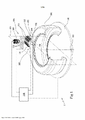
[0045] Outras características e vantagens se tornarão mais evidentes a partir da descrição detalhada de algumas modalidades exemplificativas, mas não limitativas de um método e um aparelho para analisar pneus em uma linha de produção de pneus, de acordo com a presente invenção. Essa descrição será dada a seguir com referência às figuras anexas, providas apenas para fins ilustrativos e, portanto, não limitativos, nos quais: - a figura 1 mostra um diagrama esquemático, em termos de blocos funcionais, de um aparelho para analisar a superfície de pneus de acordo com a presente invenção; - a figura 2 mostra uma vista esquemática de uma parte do aparelho de acordo com a presente invenção de acordo com uma variante de modalidade; - as figuras 3 a 14 mostram algumas etapas do método usando uma representação visual das respectivas imagens digitais; - a figura 15 mostra um fluxograma do método da presente invenção.[0045] Other features and advantages will become more evident from the detailed description of some exemplary, but not limiting embodiments of a method and apparatus for analyzing tires on a tire production line, in accordance with the present invention. This description will be given below with reference to the accompanying figures, provided for illustrative purposes only and, therefore, not limiting, in which: - figure 1 shows a schematic diagram, in terms of functional blocks, of an apparatus for analyzing the surface of tires according to the present invention; - figure 2 shows a schematic view of a part of the apparatus according to the present invention according to a variant embodiment; - figures 3 to 14 show some steps of the method using a visual representation of the respective digital images; - figure 15 shows a flowchart of the method of the present invention.
[0046] Com referência às figuras, o número de referência 1 geralmente indica um aparelho para analisar uma superfície de pneus em uma linha de produção de pneu de acordo com a presente invenção.[0046] With reference to the figures,
[0047] O aparelho 1 compreende um suporte 102 adaptado para suportar o pneu 200 em um costado e para rotar o mesmo em torno de um eixo geométrico de rotação 201 coincidindo com o eixo geométrico de rotação do pneu e tipicamente arranjados de acordo com a vertical. O suporte 102 é tipicamente operado por um membro de acionamento, não descrito adicionalmente e mostrado, uma vez que pode ser exemplificativamente de tipo conhecido.[0047]
[0048] O aparelho 1 compreende uma fonte 104 adaptada para emitir pelo menos uma radiação de luz para iluminar uma porção de superfície do conjunto de pneu no suporte e, a uma distância da dita fonte, um sistema de detecção 105 adaptado para detectar uma intensidade óptica da radiação de luz refletida e/ou difundida pela porção de superfície.[0048] The
[0049] O sistema de detecção 105 compreende uma câmera, preferivelmente linear e que tem uma linha objetiva 106 situada em um plano óptico 107 que passa pela câmera linear e pelo eixo geométrico de rotação 201.[0049] The
[0050] A fonte 104 compreende uma primeira fonte de luz 108, uma segunda fonte de luz 109 e uma terceira fonte de luz 110 adaptada para emitir uma primeira, uma segunda e uma terceira radiação de luz, respectivamente, para iluminar uma porção de superfície linear 211 do dito pneu coincidindo com a linha objetiva (por exemplo, quando a porção da superfície é planar) ou na proximidade da linha objetiva (devido à tendência curvilínea da superfície do pneu).[0050] The
[0051] O sistema de detecção 105 é adaptado para adquirir uma imagem digital bidimensional respectiva da porção de superfície linear da superfície iluminada por pelo menos uma das primeira, segunda e terceira radiação de luz.[0051] The
[0052] Tipicamente, o aparelho compreende um braço robótico (não mostrado) no qual a primeira, segunda e terceira fonte de luz e o sistema de detecção estão montados.[0052] Typically, the apparatus comprises a robotic arm (not shown) on which the first, second and third light sources and detection system are mounted.
[0053] Preferivelmente, a primeira fonte de luz 108 e a segunda fonte de luz 109 consistem cada uma em uma única subfonte respectiva 111 e 112. Preferivelmente, a terceira fonte de luz 110 consiste em quatro subfontes respectivas 113 distribuídas em ambos os lados do plano óptico 107 e simetricamente em relação a tal plano.[0053] Preferably, the first
[0054] Cada subfonte 111-113 tem uma respectiva direção principal de desenvolvimento que se desenvolve paralelamente ao plano óptico 107 e, portanto, à linha objetiva 106.[0054] Each subsource 111-113 has a respective main direction of development that develops parallel to the
[0055] Cada subfonte normalmente compreende uma pluralidade de fontes de luz LED colocadas alinhadas ao longo da direção principal de desenvolvimento.[0055] Each subsource normally comprises a plurality of LED light sources placed in a line along the main development direction.
[0056] Na figura 2, as subfontes de luz são mostradas esquematicamente com referência à sua respectiva superfície emissora (exemplificativamente de forma retangular), que pode, por exemplo, coincidir com um vidro transparente de proteção e/ou difusor. Exemplificativamente, as subfontes têm uma dimensão ao longo da direção principal de desenvolvimento igual a 6 cm e uma dimensão ao longo da direção ortogonal à direção principal de desenvolvimento igual a cerca de 1 cm.[0056] In figure 2, the light sources are schematically shown with reference to their respective emitting surface (eg rectangular shape), which can, for example, coincide with a transparent protective glass and/or diffuser. For example, sub-sources have a dimension along the main direction of development equal to 6 cm and a dimension along the direction orthogonal to the main direction of development equal to about 1 cm.
[0057] Preferivelmente, as subfontes 111 e 112 ficam em lados opostos, respectivamente, em relação ao plano óptico e são equidistantes a partir do mesmo.[0057] Preferably, the
[0058] Preferivelmente, a distância das subfontes 113 da terceira fonte de luz do plano óptico 107 é menor que a distância entre cada subfonte da dita primeira fonte de luz e segunda fonte de luz e o plano óptico.[0058] Preferably, the distance of the
[0059] Preferivelmente, a terceira fonte de luz 110 é adaptada para iluminar a linha objetiva com luz difusa (por exemplo, um ângulo respectivo tendo o seu vértice em cada ponto da linha objetiva e em um plano ortogonal à linha objetiva e subtendido pela terceira fonte de luz é igual a cerca de 80°).[0059] Preferably, the third
[0060] Em uma modalidade do aparelho particularmente adaptada para a inspeção da superfície interna do pneu, mostrada exemplificativamente na Fig. 2, o sistema de detecção inclui um espelho 150 (tipicamente também montado no braço robótico) tendo uma superfície refletora plana colocada na terceira fonte de luz perpendicular ao plano óptico e cruzando a última na linha mediana do espelho, de modo a refletir a linha objetiva no plano óptico em um ângulo exemplificativamente igual a 90°.[0060] In an embodiment of the apparatus particularly adapted for the inspection of the inner surface of the tire, shown as an example in Fig. 2, the detection system includes a mirror 150 (typically also mounted on the robotic arm) having a flat reflecting surface placed on the third light source perpendicular to the optical plane and crossing the last at the midline of the mirror so as to reflect the objective line. in the optical plane at an angle, for example, equal to 90°.
[0061] Preferivelmente, uma unidade de comando e controle 140 é constituída, configurada para ativar em uma sequência alternada a primeira, segunda e terceira fonte de luz, e controlar a câmera linear para adquirir uma primeira, segunda e terceira imagem, respectivamente, em sincronização com a ativação da primeira, segunda e terceira fonte de luz, respectivamente.[0061] Preferably, a command and
[0062] A unidade de comando e controle normalmente é configurada para controlar também o membro de manipulação do suporte 102.[0062] The command and control unit is normally configured to also control the
[0063] O aparelho compreende uma unidade de processamento (por exemplo integrada na unidade de comando e controle 140 ou em comunicação com a mesma ou com o sistema de detecção 105 para receber as ditas imagens adquiridas) configurada para implementar o método de acordo com a presente invenção.[0063] The apparatus comprises a processing unit (for example integrated in the command and
[0064] Em funcionamento, um pneu 200 é colocado no suporte 102 e submetido a uma rotação (preferivelmente completa) em torno de seu eixo geométrico de simetria 201 de modo a detectar uma imagem digital bidimensional de uma porção de superfície interna, preferivelmente ao longo de todo o desenvolvimento circunferencial.[0064] In operation, a
[0065] Durante a rotação, a unidade de comando e controle ativa ciclicamente, em sequência alternada rápida, a dita primeira, segunda e terceira fonte de luz e ativa a câmera linear para adquirir uma respectiva imagem digital linear bidimensional (colorida ou monocromática) da respectiva porção de superfície linear em sincronia com a ativação da primeira, segunda e terceira fonte de luz, respectivamente. A título de exemplo, cada imagem digital linear única compreende 1x2048 pixels no caso da câmera monocromática, ou 2x2048 pixels no caso de cores RGB ou câmeras bilineares.[0065] During rotation, the command and control unit cyclically activates, in rapid alternating sequence, said first, second and third light source and activates the linear camera to acquire a respective two-dimensional linear digital image (color or monochrome) of the respective portion of the linear surface in sync with the activation of the first, second and third light source, respectively. By way of example, each single linear digital image comprises 1x2048 pixels in the case of monochrome camera, or 2x2048 pixels in the case of RGB color or bilinear cameras.
[0066] A título de exemplo, o intervalo de tempo entre a aquisição da primeira e segunda imagem linear, bem como entre a segunda e a terceira imagem linear e, em seguida, ciclicamente entre a primeira e a terceira imagem linear, é inferior a 0,2 milissegundos.[0066] By way of example, the time interval between the acquisition of the first and second linear image, as well as between the second and third linear image and then cyclically between the first and third linear image, is less than 0.2 milliseconds.
[0067] Uma vez realizada a rotação desejada do pneu para escanear a porção de superfície desejada, preferivelmente pelo menos uma rotação total para adquirir todo o desenvolvimento circular, obtém-se uma imagem digital única, feita com todas as imagens digitais lineares da sequência de porções lineares, cada uma delas iluminada com as três fontes de luz.[0067] Once the desired tire rotation is performed to scan the desired surface portion, preferably at least one full rotation to acquire the entire circular development, a single digital image is obtained, made with all the linear digital images of the sequence of linear portions, each illuminated with the three light sources.
[0068] A unidade de processamento recebe essa imagem a partir do sistema de detecção e separa da mesma a primeira, segunda e terceira imagens correspondentes da totalidade da porção de superfície desejada.[0068] The processing unit receives this image from the detection system and separates from it the corresponding first, second and third images of the entire desired surface portion.
[0069] Tais imagens podem ser substancialmente sobrepostas, pixel por pixel, embora a porção de superfície linear real associada a uma única imagem linear não corresponda exatamente às três imagens, devido à rotação do pneu ocorrida enquanto isso. No entanto, a seleção da frequência de aquisição das imagens lineares e da velocidade de rotação é tal que as três imagens lineares estão mutuamente entrelaçadas e, portanto, podem ser comparadas pixel por pixel.[0069] Such images can be substantially superimposed, pixel by pixel, although the portion of the actual linear surface associated with a single linear image does not exactly match the three images, due to the tire rotation occurring in the meantime. However, the selection of the acquisition frequency of the linear images and the rotation speed is such that the three linear images are mutually interlaced and therefore can be compared pixel by pixel.
[0070] A Figura 3 mostra uma representação visual exemplificativa em escala de cinza de um exemplo da dita primeira imagem, isto é, de uma imagem digital bidimensional, adquirida na faixa de frequência visível, de uma porção de superfície interna de um pneu iluminado com luz difusa (totalmente semelhante a uma imagem em preto e branco comum). A direção circunferencial do pneu é colocada ao longo da direção horizontal na figura (linha reta 300).[0070] Figure 3 shows an exemplary visual representation in gray scale of an example of said first image, that is, a two-dimensional digital image, acquired in the visible frequency range, of a portion of the inner surface of a tire illuminated with diffused light (totally similar to an ordinary black and white image). The circumferential direction of the tire is placed along the horizontal direction in the figure (straight line 300).
[0071] No exemplo da figura 3, cada pixel da imagem digital está associado a um valor escalar (nível ou escala de cinza) em uma escala de 255 níveis diretamente representativa da refletividade e/ou difusividade e/ou cor do ponto de superfície interna correspondente para o pixel considerado. A presente invenção também pode ser aplicada a imagens digitais em que cada pixel está associado a um valor vetorial, como imagens coloridas digitais. Por exemplo, o método aqui descrito pode ser realizado em cada canal/cor ou combinações dos mesmos, ou em um canal selecionado (por exemplo, verde, o que vantajosamente proporciona uma melhor qualidade de imagem).[0071] In the example of figure 3, each pixel of the digital image is associated with a scalar value (level or gray scale) on a scale of 255 levels directly representative of the reflectivity and/or diffusivity and/or color of the inner surface point corresponding to the considered pixel. The present invention can also be applied to digital images where each pixel is associated with a vector value, such as digital color images. For example, the method described here can be performed on each channel/color or combinations thereof, or on a selected channel (e.g. green, which advantageously provides better image quality).
[0072] A imagem digital na qual o método aqui descrito é realizada pode coincidir com a imagem digital diretamente detectada pelo sistema de detecção ou, mais preferivelmente, pode ser submetida, antes de realizar o método aqui descrito, a um pré-processamento para melhorar a qualidade da mesma. O dito pré-processamento pode compreender uma ou mais filtragem, equilíbrio, reduções de ruído, suavização, por exemplo, como é conhecido na técnica. Daqui em diante, presume-se que esse pré-processamento não altera a natureza digital bidimensional da imagem, de modo que cada pixel está associado a um valor de luminosidade (ou tom) representativo da refletividade e/ou difusividade e/ou cor da superfície interna.[0072] The digital image on which the method described herein is performed may match the digital image directly detected by the detection system or, more preferably, may be subjected, before carrying out the method described herein, to a pre-processing to improve the quality of it. Said pre-processing may comprise one or more filtering, balancing, noise reductions, smoothing, for example, as is known in the art. Henceforth, it is assumed that this pre-processing does not alter the two-dimensional digital nature of the image, so that each pixel is associated with a luminosity (or tone) value representative of the reflectivity and/or diffusivity and/or surface color. internal.
[0073] Conforme observado na figura 3, a superfície interna do pneu é sulcada por uma pluralidade de relevos que formam um “padrão”. A presença dos relevos produz uma variação na refletividade da superfície interna detectada pela câmera. A presente invenção é também aplicável a padrões de baixo relevo ou simplesmente bidimensionais, isto é, consistindo apenas em uma variação de cor e/ou refletividade e desprovida de profundidade. Tipicamente, o padrão compreende uma série de seções retilíneas 301 substancialmente mutuamente paralelas, tipicamente distribuídas com periodicidade substancial ao longo da direção circunferencial, e uma rede densa (no jargão denominada “borda de seixo”) de segmentos substancialmente retilíneos 302 interconectados em uma rede substancialmente contínua, sendo o padrão tipicamente caracterizado por uma periodicidade substancial do mesmo ao longo da direção circunferencial. Nota-se que o padrão se desenvolve na superfície interna do pneu, que é provido com sua própria curvatura.[0073] As seen in figure 3, the inner surface of the tire is grooved by a plurality of reliefs that form a "pattern". The presence of the reliefs produces a variation in the reflectivity of the internal surface detected by the camera. The present invention is also applicable to low relief or simply two-dimensional patterns, that is, consisting only of a variation in color and/or reflectivity and devoid of depth. Typically, the pattern comprises a series of substantially mutually parallel
[0074] Preferivelmente, o padrão consiste em linhas tracejadas fechadas (polígonos) conectadas entre si. Tipicamente, o padrão consiste em polígonos adjacentes um ao outro (por exemplo, é desprovido de polígonos isolados).[0074] Preferably, the pattern consists of closed dashed lines (polygons) connected together. Typically, the pattern consists of polygons adjacent to each other (eg, it is devoid of isolated polygons).
[0075] O padrão tem um esquema que é repetido substancialmente igual ao mesmo em uma pluralidade de posições distribuídas ao longo da direção circunferencial, tipicamente com uma periodicidade circunferencial substancial (por exemplo, com uma variação do período local, em valor absoluto, ficando dentro de 5% do período médio calculado em toda a imagem), ainda mais tipicamente com continuidade ao longo de toda a imagem digital. No exemplo mostrado, a borda do seixo tem uma periodicidade circunferencial igual ao dobro da periodicidade do estriamento, pelo que a periodicidade geral do padrão é igual à da borda do seixo.[0075] The pattern has a pattern that is repeated substantially the same in a plurality of positions distributed along the circumferential direction, typically with substantial circumferential periodicity (e.g. with a local period variation, in absolute value, falling within 5% of the average period calculated over the entire image), even more typically with continuity throughout the entire digital image. In the example shown, the edge of the pebble has a circumferential periodicity equal to twice the periodicity of the striation, so the general periodicity of the pattern is equal to that of the edge of the pebble.
[0076] Como afirmado acima, os relevos 301, 302 são a impressão deixada pela bexiga pneumática. Na prática, o dito esquema é tipicamente repetido ao longo da direção circunferencial com pequenas variações na periodicidade e/ou formato e/ou orientação e/ou posição axial, permanecendo substancialmente igual, tais variações sendo devidas, por exemplo, à não uniformidade da expansão e/ou posicionamento da bexiga e/ou pequenas distorções do padrão impresso na própria bexiga e/ou fenômenos de distorção no processo de detecção de imagem (por exemplo, devido a uma centralização defeituosa do eixo geométrico de rotação do pneu, circularidade não perfeita do pneu, etc.).[0076] As stated above, the
[0077] Para mais clareza, a figura 3 mostra uma porção de imagem digital circunferencial longa, ao longo da direção 300, apenas duas vezes e meia em torno do período do padrão; no entanto, tipicamente a imagem digital processada corresponde a uma porção de superfície interna circunferencial compreendendo o dito esquema repetido pelo menos oito a dez vezes. Preferivelmente, a porção de superfície interna circunferencial processada abrange todo o desenvolvimento interno circunferencial do pneu.[0077] For clarity, Figure 3 shows a long circumferential digital image portion, along
[0078] Tipicamente, a imagem digital processada corresponde a uma porção da superfície interna com um comprimento na direção axial (a direção perpendicular à direção 300 na figura 3) de pelo menos 5 cm, preferivelmente igual a pelo menos metade do desenvolvimento axial global da coroa do pneu.[0078] Typically, the processed digital image corresponds to a portion of the inner surface with a length in the axial direction (the direction perpendicular to
[0079] A Figura 3 é mostrada como um defeito exemplificativo 303 (mostrado ampliado na figura 3a que mostra um detalhe rotado da figura 3) consistindo em um corte que atravessa pelo menos um segmento do padrão.[0079] Figure 3 is shown as an exemplary defect 303 (shown enlarged in Figure 3a showing a rotated detail of Figure 3) consisting of a cut through at least one segment of the pattern.
[0080] Preferivelmente, o método provê derivar um valor representativo do período de padrão através do processamento de imagem digital, por exemplo, buscando o máximo de uma função de autocorrelação (por exemplo, o coeficiente de correlação de Pearson calculado sobre os valores associados aos pixels da imagem) entre uma porção dada (no jargão chamado ‘suporte’) da imagem digital (tendo dimensões adequadas, por exemplo, comprimento circunferencial maior que o período e menor do que três vezes o período) e uma pluralidade de porções adicionais da imagem digital tendo dimensões iguais às dimensões da dita dada porção de imagem e arranjadas em posições distribuídas circunferencialmente. Preferivelmente, a autocorrelação circunferencial é calculada repetidamente com referência a vários suportes diferentes e parcialmente sobreposição na direção axial da imagem e tendo as mesmas dimensões, com o objetivo de selecionar o pico de autocorrelação mais confiável para identificar o período do padrão. Alternativamente, é provido para adquirir um valor predeterminado do período, por exemplo, a partir de uma medida e/ou das especificações da bexiga.[0080] Preferably, the method provides for deriving a value representative of the pattern period through digital image processing, for example, seeking the maximum of an autocorrelation function (for example, Pearson's correlation coefficient calculated on the values associated with the image pixels) between a given portion (in jargon called 'support') of the digital image (having suitable dimensions, e.g. circumferential length greater than the period and less than three times the period) and a plurality of additional portions of the image digital image having dimensions equal to the dimensions of said given image portion and arranged in circumferentially distributed positions. Preferably, the circumferential autocorrelation is calculated repeatedly with reference to several different supports and partially overlapping in the axial direction of the image and having the same dimensions, in order to select the most reliable autocorrelation peak to identify the period of the pattern. Alternatively, it is provided to acquire a predetermined period value, for example from a measurement and/or bladder specification.
[0081] O método envolve a identificação de uma primeira região 304 da imagem digital correspondente a uma subporção do esquema, por exemplo tendo um desenvolvimento circunferencial menor do que todo um desenvolvimento circunferencial do esquema (no exemplo igual a cerca de um terço do desenvolvimento circunferencial do esquema, coincidindo com o dito período). As dimensões da primeira região são vantajosamente consistentes com as dimensões típicas esperadas do defeito procurado.[0081] The method involves identifying a
[0082] É adicionalmente provido para identificar uma respectiva pluralidade de regiões 305, 306 da imagem digital homóloga à primeira região 304 e distribuída ao longo da direção circunferencial. Cada região homóloga contém uma respectiva subporção do esquema substancialmente idêntica à subporção do esquema da primeira região. Para este fim, uma função de correlação é calculada (por exemplo, o coeficiente de correlação de Pearson) entre a primeira região e uma porção do resto da imagem digital. Preferivelmente, uma primeira região homóloga 305 é primeiro identificada calculando a função de correlação entre a primeira região 304 e uma pluralidade de regiões com dimensões iguais à primeira região e arranjadas em uma vizinhança de um ponto da imagem digital distante circunferencialmente da primeira região por uma distância igual a um período P. Por exemplo, se as coordenadas do centro da primeira região 304 forem x0, y0, uma primeira região de dimensões iguais é identificada pela primeira vez, com as coordenadas x0, y0+P no centro. Então, a função de correlação é calculada entre a primeira região e todas as regiões das mesmas dimensões cujo centro está localizado na vizinhança de coordenadas x0±Δx, y0+P±Δy, com Δx, Δy iguais a um número apropriado de pixels, por exemplo, 5 a 10 pixels. A região com coordenadas x1, y1 no centro, em que a função de correlação exibe um máximo (pelo menos local), é identificada como a primeira região homóloga 305.[0082] It is further provided to identify a respective plurality of
[0083] O algoritmo é repetido a partir da primeira região homóloga 305 e buscando um máximo de correlação na vizinhança de coordenadas x1±Δx, y1+P±Δy, a fim de localizar a segunda região homóloga 306 (tendo no centro as coordenadas x2, y2), e assim por diante de forma iterativa, de modo a identificar uma sequência de regiões homólogas em sucessão. Em particular, uma tupla de coordenadas xn, yn é calculada, correspondente ao centro (ou qualquer outro ponto de referência) da tupla de regiões homólogas.[0083] The algorithm is repeated starting from the first
[0084] No exemplo aqui descrito, a aquisição do valor representativo do período de padrão processando a imagem digital e identificando essa tupla de coordenadas é realizada na imagem em luz difusa (do tipo mostrado na figura 3).[0084] In the example described here, the acquisition of the representative value of the pattern period by processing the digital image and identifying this tuple of coordinates is performed on the image in diffuse light (of the type shown in figure 3).
[0085] No entanto, o Requerente verificou que podem ser obtidos resultados ainda mais robustos se as operações de cálculo do período e/ou a identificação dessa tupla (por exemplo, a identificação de regiões homólogas através de autocorrelação) forem realizadas em uma imagem de diferença, na qual cada pixel é associado a um valor representativo da diferença dos valores de luminosidade correspondentes das segundas e terceiras imagens adquiridas em luz tangencial, conforme descrito acima.[0085] However, the Applicant has found that even more robust results can be obtained if the period calculation operations and/or the identification of this tuple (for example, the identification of homologous regions through autocorrelation) are performed on an image of difference, in which each pixel is associated with a value representative of the difference from the corresponding luminosity values of the second and third images acquired in tangential light, as described above.
[0086] Essa tupla de coordenadas é então mostrada na primeira imagem em luz difusa para identificar uma primeira região correspondente e uma pluralidade correspondente de regiões homólogas na dita primeira imagem.[0086] That tuple of coordinates is then shown in the first image in diffused light to identify a corresponding first region and a corresponding plurality of homologous regions in said first image.
[0087] É adicionalmente provida para calcular um modelo da subporção do esquema, em que cada pixel está associado a um valor médio dos valores associados aos pixels da primeira região e das respectivas regiões homólogas da primeira imagem que tem a mesmas coordenadas do dito cada pixel.[0087] It is additionally provided to calculate a model of the subportion of the scheme, in which each pixel is associated with an average value of the values associated with the pixels of the first region and of the respective homologous regions of the first image that have the same coordinates of said each pixel .
[0088] Para este fim, para fins de ilustração, a figura 4 mostra uma representação gráfica 3D de uma pilha 307 de regiões obtidas por sobreposição da primeira região (por exemplo, na base da pilha) e todas as suas respectivas regiões homólogas da primeira imagem em luz difusa. Como pode ser visto, cada pixel na base da pilha corresponde a um conjunto de valores estatísticos (escala escalar ou cinza) na coluna vertical correspondente. Esse conjunto estatístico tem uma variância intrínseca devido às deformações descritas acima.[0088] To this end, for purposes of illustration, Figure 4 shows a 3D graphical representation of a
[0089] Preferivelmente, o modelo digital 308 da subporção do esquema (mostrado na figura 5) associado à primeira região 304 é calculado considerando o valor médio do conjunto estatístico correspondente para cada pixel da base da pilha. Portanto, é gerado um modelo 308 que tem em cada pixel de coordenada relativo (i,j) o valor médio (por exemplo, nível de cinza) calculado em todos os pixels de coordenadas relativos (i,j) do conjunto da primeira região e das regiões homólogas. Como pode ser visto na figura 5, o modelo assim calculado não contém contribuições de quaisquer defeitos, além de apresentar uma alta qualidade de imagem (por exemplo, em termos de ruído e/ou nitidez).[0089] Preferably, the
[0090] Preferivelmente, um modelo digital da respectiva subporção do esquema é calculado de acordo com o apresentado acima para uma pluralidade de primeiras regiões, cada uma compreendendo a respectiva subporção do esquema. As primeiras regiões formam uma porção de imagem digital conectada com desenvolvimento circunferencial aproximadamente igual ao período. Desta forma, um modelo digital é calculado para todo o esquema que compõe o padrão. Preferivelmente, as primeiras regiões estão parcialmente sobrepostas na direção axial e/ou na direção circunferencial, de modo a melhorar a confiabilidade do método.[0090] Preferably, a digital model of the respective sub-portion of the scheme is calculated as presented above for a plurality of first regions, each comprising the respective sub-portion of the scheme. The first regions form a connected digital image portion with circumferential development approximately equal to the period. In this way, a digital model is calculated for the entire scheme that makes up the pattern. Preferably, the first regions are partially overlapping in the axial direction and/or in the circumferential direction, in order to improve the reliability of the method.
[0091] Uma vez que os modelos das respectivas subporções foram construídos, um modelo de padrão é obtido substituindo, na dita primeira imagem, o dito modelo da respectiva subporção de esquema para cada primeira região e para as respectivas regiões homólogas. Pelo procedimento de autoaprendizagem acima, obtém-se uma imagem que é um modelo global da porção de superfície sem defeitos, que é facilmente comparável à imagem real.[0091] Once the models of the respective sub-portions have been constructed, a pattern model is obtained by substituting, in said first image, said model of the respective schematic sub-portion for each first region and for the respective homologous regions. By the above self-learning procedure, an image is obtained which is a global model of the defect-free portion of the surface, which is easily comparable to the real image.
[0092] Para efeitos desta comparação, é vantajoso usar o módulo de gradiente e a orientação como se descreve a seguir.[0092] For the purposes of this comparison, it is advantageous to use the gradient module and orientation as described below.
[0093] Em uma modalidade, para cada pixel do modelo de padrão em valores de luminosidade calculados na primeira imagem, é contemplado calcular um valor de módulo e um valor de orientação de um gradiente dos valores de luminosidade associados aos pixels, obtendo assim um modelo de padrão em valores de módulo de gradiente e em valores de orientação de gradiente, respectivamente. Para reduzir o uso de recursos de computação, é preferível calcular esses valores de módulo de gradiente e orientação de gradiente em cada modelo de subporção de esquema em valores de luminosidade e, em seguida, proceder com a operação acima de obter um modelo de padrão por substituição.[0093] In one embodiment, for each pixel of the pattern model in luminosity values calculated in the first image, it is contemplated to calculate a module value and an orientation value of a gradient of the luminosity values associated with the pixels, thus obtaining a model pattern into gradient modulus values and gradient orientation values, respectively. To reduce the use of computing resources, it is preferable to calculate these gradient modulus and gradient orientation values in each schema sub-portion model in luminosity values and then proceed with the above operation to get a pattern model by replacement.
[0094] Em uma modalidade alternativa e preferida, as operações descritas acima para a identificação de regiões homólogas e o cálculo de um respectivo modelo de subporção do esquema (preferivelmente, através do uso de uma tupla de coordenadas identificadas na imagem de diferença) são conduzidos nos valores de módulo de gradiente e nos valores de orientação do gradiente calculados na primeira imagem em valores de luminosidade. Nesse caso, não é estritamente necessário calcular o modelo de padrão em valores de luminosidade na primeira imagem.[0094] In an alternative and preferred embodiment, the operations described above for the identification of homologous regions and the calculation of a respective model subportion of the schema (preferably, through the use of a tuple of coordinates identified in the difference image) are conducted in the gradient modulus values and in the gradient orientation values calculated in the first image in lightness values. In this case, it is not strictly necessary to calculate the pattern model in lightness values in the first image.
[0095] Para calcular o módulo de gradiente e os valores de orientação, o gradiente dos valores de luminosidade é calculado para cada pixel de imagem digital ao longo das duas coordenadas horizontais e verticais da imagem, obtendo assim um vetor com dois componentes: um módulo (por exemplo, a raiz da soma quadrática dos dois componentes) e uma orientação na imagem digital (por exemplo, o ângulo formado pelo vetor em relação à direção horizontal), normalizado na faixa [0 a 180°] ou [-90° a +90°].[0095] To calculate the gradient modulus and orientation values, the gradient of the luminosity values is calculated for each digital image pixel along the two horizontal and vertical coordinates of the image, thus obtaining a vector with two components: a module (for example, the root of the quadratic sum of the two components) and an orientation in the digital image (for example, the angle formed by the vector with respect to the horizontal direction), normalized in the range [0 to 180°] or [-90° to +90°].
[0096] Para calcular o módulo de gradiente e os valores de orientação, é, por exemplo, proceder da seguinte forma: sendo I(x,y) cada pixel da imagem de entrada (a notação (x,y) é omitida quando desnecessário), o seguinte é calculado: • Ix= I * Kx, onde ‘*’ é o operador de convolução, e Kx é um núcleo apropriado para o cálculo da primeira derivada em x (por exemplo, Kx = [ 1 -1 ] ) • Iy= I * Ky, onde ‘*’ é o operador de convolução, e Ky é um núcleo apropriado para o cálculo da primeira derivada em y (por exemplo, Ky = [ 1 -1 ] ) • Grad(x,y) = [ Ix; Iy ] = gradiente de I(x,y) • módulo de gradiente = sqrt( (Ix)A2 + (Iy)A2 ) • orientação de gradiente = arctan( Iy / Ix )[0096] To calculate the gradient modulus and orientation values, for example, proceed as follows: with I(x,y) being each pixel of the input image (the notation (x,y) is omitted when unnecessary ), the following is calculated: • Ix= I * Kx, where '*' is the convolution operator, and Kx is a suitable kernel for computing the first derivative in x (for example, Kx = [ 1 -1 ] ) • Iy= I * Ky, where '*' is the convolution operator, and Ky is a suitable kernel for computing the first derivative in y (eg, Ky = [ 1 -1 ] ) • Grad(x,y) = [ ix; Iy ] = gradient of I(x,y) • gradient modulus = sqrt( (Ix)A2 + (Iy)A2 ) • gradient orientation = arctan( Iy / Ix )
[0097] A Figura 6 mostra uma visualização exemplificativa de uma subporção de superfície correspondente a uma porção central da imagem na figura 3, em que cada pixel está associado a um nível de cinza representativo do (por exemplo, proporcional ao) módulo de gradiente no pixel considerado (por exemplo, pixels de luz correspondem a um módulo de gradiente alto e vice-versa).[0097] Figure 6 shows an exemplary visualization of a surface subportion corresponding to a central portion of the image in Figure 3, in which each pixel is associated with a gray level representative of (for example, proportional to) the gradient module in the image. considered pixel (for example, light pixels correspond to a high gradient modulus and vice versa).
[0098] A Figura 7 mostra uma visualização exemplificativa da mesma subporção de superfície na figura 6, na qual cada pixel está associado a um nível de cinza representativo unicamente da orientação do gradiente no pixel considerado.[0098] Figure 7 shows an exemplary visualization of the same surface sub-portion in figure 6, in which each pixel is associated with a gray level representative only of the gradient orientation in the considered pixel.
[0099] Uma comparação entre as figuras 6 e 7 mostra que as zonas de módulo de gradiente baixo do padrão são caracterizadas por um valor de orientação não significativo (variável desordenada).[0099] A comparison between figures 6 and 7 shows that the low gradient modulus zones of the pattern are characterized by a non-significant orientation value (disordered variable).
[00100] Como dito acima, executando as seguintes operações nas imagens digitais, como mostrado nas figuras 6 e 7: identificando uma pluralidade de primeiras regiões; para cada primeira região, identificando uma respectiva pluralidade de regiões homólogas; e calculando um modelo respectivo, o modelo de padrão é obtido em valores de módulo de gradiente e valores de orientação de gradiente, respectivamente.[00100] As stated above, performing the following operations on the digital images, as shown in figures 6 and 7: identifying a plurality of first regions; for each first region, identifying a respective plurality of homologous regions; and calculating a respective model, the pattern model is obtained in gradient modulus values and gradient orientation values, respectively.
[00101] Neste ponto, o modelo de padrão resultante (seja em valores de luminosidade e/ou valores de módulo e/ou valores de orientação de gradiente) é submetido à dilatação para introduzir uma tolerância que tenha em conta as deformações e/ou derivações do esquema no padrão.[00101] At this point, the resulting pattern model (either in luminosity values and/or modulus values and/or gradient orientation values) is subjected to dilation to introduce a tolerance that takes into account the deformations and/or derivations of the schema in the pattern.
[00102] Em uma primeira modalidade preferida, o modelo de padrão em valores de módulo de gradiente é primeiro binarizado (por exemplo, limitando com um único ou duplo limiar) para obter um modelo binário do padrão.[00102] In a first preferred embodiment, the pattern model in gradient modulus values is first binarized (eg, bounding with a single or double threshold) to obtain a binary model of the pattern.
[00103] Esse modelo binário do padrão é submetido à dilatação (por exemplo, por meio de uma operação de processamento morfológico) para obter um modelo binário de padrão dilatado em que os pixels têm um primeiro índice binário associado, cujo valor é indicativo de se o pixel pertence ou não aos padrões dilatados, respectivamente (para distinguir os pixels pertencentes ao plano de fundo dos pertencentes ao padrão dilatado da primeira imagem em comparação com tal modelo binário dilatado).[00103] This binary model of the pattern is subjected to dilatation (e.g., through a morphological processing operation) to obtain a binary model of the dilated pattern in which the pixels have a first associated binary index, whose value is indicative of whether the pixel belongs or does not belong to the dilated patterns, respectively (to distinguish the pixels belonging to the background from those belonging to the dilated pattern of the first image compared to such a dilated binary model).
[00104] Além disso, os valores de orientação do gradiente do modelo de padrão também são preferivelmente submetidos à dilatação. Preferivelmente, cada pixel do modelo binário de padrão dilatado pertencente ao padrão dilatado está associado a um segundo índice, cujo valor é representativo da orientação da seção de padrão dilatada passando pelo pixel: por exemplo, o valor de orientação do gradiente do pixel com um valor de módulo de gradiente máximo em uma vizinhança predeterminada (por exemplo igual a 5 a 10 pixels de raio) do dito cada pixel no dito modelo de padrão pode ser selecionado.[00104] In addition, the gradient orientation values of the pattern model are also preferably subjected to dilation. Preferably, each pixel of the dilated pattern binary model belonging to the dilated pattern is associated with a second index, whose value is representative of the orientation of the dilated pattern section passing through the pixel: for example, the pixel gradient orientation value with a value of maximum gradient modulus in a predetermined neighborhood (e.g. equal to 5 to 10 pixels in radius) of said each pixel in said pattern template can be selected.
[00105] Em uma segunda modalidade alternativa, os valores do módulo de gradiente e os valores de orientação do gradiente do modelo de padrão são primeiro submetidos à dilatação. Por exemplo, cada pixel do modelo de padrão dilatado é atribuído como valor de módulo de gradiente o valor máximo do módulo de gradiente em uma vizinhança predeterminada do dito pixel no modelo de padrão (sendo a dita vizinhança exemplificativamente um raio igual a 5 a 10 pixels) e como valor de orientação do gradiente que está associado ao pixel com o dito valor do módulo de gradiente máximo. Subsequentemente, o modelo de padrão assim obtido é binarizado com base no valor do módulo de gradiente, obtendo assim o valor do dito primeiro índice.[00105] In a second alternative embodiment, the gradient modulus values and the pattern template gradient orientation values are first subjected to dilation. For example, each pixel of the dilated pattern model is assigned as the gradient modulus value the maximum value of the gradient modulus in a predetermined neighborhood of said pixel in the pattern model (said neighborhood being, for example, a radius equal to 5 to 10 pixels ) and as an orientation value of the gradient that is associated with the pixel with said value of the maximum gradient modulus. Subsequently, the pattern model thus obtained is binarized based on the value of the gradient modulus, thus obtaining the value of said first index.
[00106] A Figura 8 mostra um exemplo de modelo de padrão obtido como resultado das ditas operações nas duas modalidades. Cada pixel da imagem na figura 8 que não pertence ao padrão dilatado, mas ao plano de fundo do padrão (por exemplo, com o valor do dito primeiro índice igual a zero) é mostrado em preto. Cada pixel pertencente ao padrão dilatado (por exemplo, com o valor do dito primeiro índice igual a um) é mostrado em um nível de cinza diferente de preto, onde cada nível de cinza biunicamente corresponde a um valor do segundo índice representativo da orientação do segmento correspondente do padrão dilatado passando pelo pixel considerado. Como pode ser visto, os pixels fora do padrão dilatado (pixels pretos) não têm um valor significativo associado ao segundo índice.[00106] Figure 8 shows an example of a pattern model obtained as a result of said operations in the two modalities. Each pixel of the image in figure 8 that does not belong to the dilated pattern, but to the background of the pattern (for example, with the value of said first index equal to zero) is shown in black. Each pixel belonging to the dilated pattern (for example, with the value of said first index equal to one) is shown in a gray level other than black, where each gray level biuniquely corresponds to a value of the second index representative of the segment orientation. corresponding to the dilated pattern passing through the considered pixel. As can be seen, pixels outside the dilated pattern (black pixels) do not have a significant value associated with the second index.
[00107] Antes de fazer a comparação entre a primeira imagem do pneu adquirida em luz difusa em valores de luminosidade e o modelo de padrão dilatado como obtido acima, é vantajoso processar essa primeira imagem para destacar os possíveis defeitos do resto da imagem.[00107] Before making the comparison between the first image of the tire acquired in diffused light in brightness values and the dilated pattern model as obtained above, it is advantageous to process this first image to highlight possible defects from the rest of the image.
[00108] Para apoiar a descrição do método para destacar defeitos em potencial, será feita referência aos números 9 a 12.[00108] To support the description of the method for highlighting potential defects, reference will be made to numbers 9 to 12.
[00109] A Figura 9 ilustra exemplificativamente uma representação visual em escala de cinza de um exemplo adicional de uma porção da primeira imagem, de natureza semelhante à mostrada nas figuras 3 e 3a, mostrando uma outra porção de superfície interna de um pneu iluminado com luz difusa, na qual um defeito 903 está presente, consistindo em um corte que atravessa alguns segmentos do padrão. Na porção de superfície da figura 9 havia vestígios de um agente de liberação usado na bexiga, em particular nas paredes dos segmentos de padrão. Uma vez que este agente de liberação é altamente reflexivo, tais paredes dos segmentos de padrão na imagem dão origem a um par de linhas paralelas muito brilhantes 904. Uma linha mais escura 905 está presente entre as duas linhas brilhantes que correspondem ao “topo” dos segmentos de padrão, menos sujos com o agente de liberação. Em tal situação, em princípio, os segmentos 905 podem ser confundidos com os cortes 903, pois apresentam características de luminosidade semelhantes.[00109] Figure 9 exemplifies a visual representation in grayscale of an additional example of a portion of the first image, similar in nature to that shown in Figures 3 and 3a, showing another inner surface portion of a tire illuminated with light diffuse, in which a 903 defect is present, consisting of a cut through some segments of the pattern. On the surface portion of Figure 9 there were traces of a release agent used in the bladder, in particular on the walls of the pattern segments. Since this release agent is highly reflective, such walls of pattern segments in the image give rise to a pair of very bright
[00110] Para destacar os defeitos potenciais do resto da imagem, é contemplado calcular um valor representativo do autovalor principal (ou autovalor máximo) da matriz Hessiana no dito pixel para cada pixel da primeira imagem em valores de luminosidade.[00110] To highlight potential defects from the rest of the image, it is contemplated to calculate a value representative of the main eigenvalue (or maximum eigenvalue) of the Hessian matrix in said pixel for each pixel of the first image in luminosity values.
[00111] A título de exemplo, a matriz Hessiana é calculada da seguinte forma. Sendo, como acima, l(x,y) cada pixel da imagem de entrada, o seguinte é calculado: • Ixx= I * Kxx, onde ‘*’ é o operador de convolução, e Kxx é um núcleo apropriado para o cálculo da segunda derivada em x (por exemplo, Kxx = [ 1 -2 1 ] vetor de linha) • Iyy= I * Kyy, onde ‘*’ é o operador de convolução, e Kyy é um núcleo apropriado para o cálculo da segunda derivada em y (por exemplo, Kyy = [ 1; -2; 1 ] vetor de coluna) • Ixy = Iyx = I * Kxy onde ‘*’ é o operador de convolução, e Kxy é um núcleo apropriado para o cálculo da derivada mista (por exemplo, a matriz Kxy = [ 1 0 -1 ; 0 0 0; -1 0 1 ] onde “;” é o separador de linha).[00111] As an example, the Hessian matrix is calculated as follows. Since, as above, l(x,y) is each pixel of the input image, the following is calculated: • Ixx= I * Kxx, where '*' is the convolution operator, and Kxx is an appropriate kernel for calculating the second derivative on x (eg Kxx = [ 1 -2 1 ] row vector) • Iyy= I * Kyy, where '*' is the convolution operator, and Kyy is a suitable kernel for computing the second derivative in y (for example, Kyy = [ 1; -2; 1 ] column vector) • Ixy = Iyx = I * Kxy where '*' is the convolution operator, and Kxy is a suitable kernel for computing the mixed derivative ( for example, the matrix Kxy = [ 1 0 -1 ; 0 0 0; -1 0 1 ] where “;” is the line separator).
[00112] A Hessiana H = [ Ixx Ixy; Iyx Iyy ] é assim obtida.[00112] The Hessian H = [ Ixx Ixy; Iyx Iyy ] is thus obtained.
[00113] A partir da matriz Hessiana H, os autovetores e os autovalores são calculados, por exemplo, pelo algoritmo EVD (Decomposição do Autovalor/vetor).[00113] From the Hessian matrix H, the eigenvectors and the eigenvalues are calculated, for example, by the EVD algorithm (Eigenvalue/vector Decomposition).
[00114] Preferivelmente, os principais valores do autovalor são binarizados por comparação com um primeiro valor de limiar, para identificar os pixels defeituosos propostos como os pixels cujo autovalor máximo associado está acima desse primeiro valor de limiar.[00114] Preferably, the main eigenvalues are binarized against a first threshold value, to identify the proposed defective pixels as those pixels whose associated maximum eigenvalue is above that first threshold value.
[00115] A Figura 10 mostra uma visualização exemplificativa da primeira porção de imagem substancialmente correspondente à mostrada na figura 9, binarizada com base no autovalor principal. Note-se que a dita binarização aumentou tanto os pixels pertencentes ao corte 903 como os pixels nas paredes 904 (mais precisamente das áreas de transição entre o plano de fundo do padrão e as paredes 904) e das áreas centrais 905 dos segmentos de padrão 905 onde o autovalor máximo é alto.[00115] Figure 10 shows an exemplary view of the first image portion substantially corresponding to that shown in Figure 9, binarized based on the principal eigenvalue. Note that said binarization increased both the pixels belonging to the
[00116] Para eliminar pelo menos os pixels nas áreas de transição entre o plano de fundo do padrão e as paredes dos segmentos de padrão dos defeitos propostos assim obtidos, bem como outros pixels espúrios, é contemplado comparar os valores de módulo de gradiente calculados sobre os valores de luminosidade da primeira imagem com um segundo valor de limiar e identificar os pixels com um valor de módulo de gradiente menor do que esse segundo valor de limiar como defeitos propostos.[00116] To eliminate at least the pixels in the transition areas between the pattern background and the walls of the pattern segments of the proposed defects thus obtained, as well as other spurious pixels, it is contemplated to compare the gradient modulus values calculated on the luminosity values of the first image with a second threshold value and identify pixels with a gradient modulus value less than that second threshold value as proposed defects.
[00117] A Figura 11 mostra substancialmente a mesma porção de imagem na figura 9 em que os pixels foram binarizados com base no módulo de gradiente (opcionalmente com operações de suavização de borda apropriadas). Os pixels brancos são aqueles com baixo valor de módulo de gradiente, isto é menor do que o segundo valor de limiar. Note-se que os pixels 904 nas bordas dos segmentos de padrão têm um alto valor de gradiente.[00117] Figure 11 shows substantially the same portion of the image as in Figure 9 where the pixels have been binarized based on the gradient module (optionally with appropriate anti-aliasing operations). White pixels are those with low gradient modulus value, ie less than the second threshold value. Note that the 904 pixels at the edges of the pattern segments have a high gradient value.
[00118] A Figura 12 mostra substancialmente a mesma porção de imagem na figura 10, em que os pixels brancos são os defeitos propostos obtidos a partir do limiar concorrente com os ditos dois valores de limiar (isto é, os pixels brancos tanto na figura 10 como na figura 11). É observado que alguns pixels 905 permanecem como defeitos propostos no centro de algumas seções de padrão, enquanto quase todos os pixels nas bordas das seções de padrão foram substancialmente filtrados pelo critério.[00118] Figure 12 shows substantially the same portion of the image in Figure 10, where the white pixels are the proposed defects obtained from the concurrent threshold with said two threshold values (i.e. the white pixels in both Figure 10 as in figure 11). It is observed that some 905 pixels remain as proposed defects in the center of some pattern sections, while almost all pixels at the edges of the pattern sections have been substantially filtered by the criterion.
[00119] A fim de selecionar adicionalmente os defeitos propostos, um terceiro critério de seleção é preferivelmente provido, preferivelmente usado em combinação com os ditos dois outros critérios, com base no valor de luminosidade na imagem adquirida em luz difusa. Em particular, esse valor de luminosidade é comparado com um terceiro valor de limiar e todos os pixels de defeitos propostos como identificados acima são selecionados, que também têm o valor de luminosidade abaixo do terceiro valor de limiar.[00119] In order to further select the proposed defects, a third selection criterion is preferably provided, preferably used in combination with said two other criteria, based on the brightness value in the image acquired in diffuse light. In particular, this luminosity value is compared with a third threshold value and all proposed defect pixels as identified above are selected, which also have the luminosity value below the third threshold value.
[00120] Nesse ponto, é possível fazer a comparação entre os pixels de defeito propostos assim selecionados com o modelo de padrão dilatado livre de defeitos conforme calculado acima, de modo a detectar quaisquer defeitos na porção de superfície em função dessa comparação.[00120] At this point, it is possible to compare the proposed defect pixels thus selected with the defect-free dilated pattern model as calculated above, in order to detect any defects in the surface portion as a function of this comparison.
[00121] Preferivelmente, um primeiro conjunto de pixels é identificado entre os ditos pixels de defeito propostos para os quais os pixels correspondentes no modelo de padrão dilatado não pertencem ao padrão dilatado (por exemplo, com referência à figura 8, as áreas de ‘plano de fundo’ preto), para identificar os defeitos (ou porções de defeito) localizados fora do padrão, ou seja, pertencendo ao ‘plano de fundo’ do padrão.[00121] Preferably, a first set of pixels is identified among said proposed defect pixels for which the corresponding pixels in the dilated pattern model do not belong to the dilated pattern (e.g. with reference to figure 8, the 'planar' areas 'background'), to identify defects (or portions of defects) located outside the pattern, i.e. belonging to the 'background' of the pattern.
[00122] Preferivelmente, é contemplado identificar um segundo conjunto de pixels entre os ditos pixels de defeito propostos que tenham o pixel correspondente no modelo de padrão pertencente ao padrão (por exemplo, os pixels em nível de cinza diferente do preto na figura 8), para os quais a pelo menos orientação local da seção de padrão que passa pelo dito modelo de padrão dilatado (representado pelo segundo valor, por exemplo, o valor de orientação do gradiente dilatado) é significativamente diferente (por exemplo, a diferença é maior que 20°) da orientação da seção formada pelos ditos defeitos propostos e passando pelo dito pixel. Nesse caso, tal seção de defeito proposta que passa pelo dito pixel é provavelmente um corte com uma porção que cruza com uma seção de padrão no dito modelo de padrão dilatado.[00122] Preferably, it is contemplated to identify a second set of pixels among said proposed defect pixels that have the corresponding pixel in the pattern model belonging to the pattern (for example, pixels in gray level other than black in figure 8), for which the at least local orientation of the pattern section passing through said dilated pattern model (represented by the second value, e.g. the dilated gradient orientation value) is significantly different (e.g. the difference is greater than 20 °) of the orientation of the section formed by said proposed defects and passing through said pixel. In that case, such a proposed defect section passing through said pixel is likely a cut with a portion that intersects with a pattern section in said dilated pattern model.
[00123] Em uma primeira modalidade, a orientação da seção formada pelos ditos defeitos propostos e passando pelo dito pixel é representada pelo valor de orientação do gradiente no dito pixel calculado como descrito acima nos valores de luminosidade na primeira imagem em luz difusa.[00123] In a first embodiment, the orientation of the section formed by said proposed defects and passing through said pixel is represented by the gradient orientation value in said pixel calculated as described above in the luminosity values in the first image in diffuse light.
[00124] Em uma segunda modalidade, a orientação da seção formada pelos ditos defeitos propostos e passando pelo dito pixel é representada pela orientação do autovetor principal da matriz Hessiana no dito pixel calculado como descrito acima nos valores de luminosidade na primeira imagem em luz difusa.[00124] In a second embodiment, the orientation of the section formed by said proposed defects and passing through said pixel is represented by the orientation of the main eigenvector of the Hessian matrix in said pixel calculated as described above in the luminosity values in the first image in diffuse light.
[00125] Preferivelmente, é contemplado fundir (em lógica OR) o primeiro e segundo conjunto de pixels para formar uma imagem final (tipicamente binária) representativa da dita porção de superfície em que os pixels correspondentes aos ditos primeiro e segundo conjuntos são distintos dos pixels restantes, como mostrado exemplificativamente na figura 13, onde se vê que tanto a porção de corte no plano de fundo do padrão como a porção cortada no padrão dilatado foram identificadas.[00125] Preferably, it is contemplated to merge (in OR logic) the first and second sets of pixels to form a final (typically binary) image representative of said surface portion wherein the pixels corresponding to said first and second sets are distinct from the pixels remainder, as shown by way of example in figure 13, where it can be seen that both the cut portion in the background of the pattern and the cut portion in the dilated pattern have been identified.
[00126] Preferivelmente, o processamento morfológico apropriado pode ser realizado nos ditos pixels para descartar falsos defeitos propostos. Por exemplo, os blocos de pixels isolados ou as regiões de pixels conectadas (‘mancha’) que não são compatíveis com os defeitos procurados são eliminados; em particular, a seleção pode ser feita por área e/ou comprimento. A Figura 14 mostra o resultado final de um processamento desse tipo realizado na imagem na figura 13.[00126] Preferably, appropriate morphological processing can be performed on said pixels to rule out false proposed defects. For example, blocks of isolated pixels or regions of connected pixels ('spot') that are not compatible with the defects sought are eliminated; in particular, the selection can be made by area and/or length. Figure 14 shows the final result of a processing of this type performed on the image in Figure 13.
[00127] A Figura 15 mostra um fluxograma do método da presente invenção em que a operação 1010 representa a operação de prover o pneu com a superfície a ser analisada.[00127] Figure 15 shows a flowchart of the method of the present invention in which
[00128] A operação 1020 representa a operação de adquirir pelo menos uma imagem digital de uma porção da dita superfície, em que cada pixel da dita imagem é associado a um valor de luminosidade representativo da refletividade e/ou difusividade e/ou cor de um ponto da superfície correspondente a dito cada pixel.[00128]
[00129] A operação 1030 representa a operação de calcular, para cada pixel de dita imagem, um primeiro parâmetro representativo de uma segunda derivada calculada em dito pixel sobre ditos valores de luminosidade.[00129]
[00130] A operação 1040 representa a operação de estabelecer se cada pixel pertence a um defeito proposto em função do dito primeiro parâmetro.[00130]
[00131] A operação 1050 representa a operação de comparar os pixels propostos como sendo defeitos com um modelo digital da porção de superfície sem defeitos e detectar possíveis defeitos na dita porção de superfície em função da dita comparação.[00131]
Claims (9)
Applications Claiming Priority (3)
| Application Number | Priority Date | Filing Date | Title |
|---|---|---|---|
| ITUB20151872 | 2015-06-30 | ||
| IT102015000028923 | 2015-06-30 | ||
| PCT/IB2016/053678 WO2017001968A1 (en) | 2015-06-30 | 2016-06-21 | Method and apparatus for detecting defects on the surface of tyres |
Publications (2)
| Publication Number | Publication Date |
|---|---|
| BR112017027101A2 BR112017027101A2 (en) | 2018-08-21 |
| BR112017027101B1 true BR112017027101B1 (en) | 2022-08-09 |
Family
ID=54200007
Family Applications (1)
| Application Number | Title | Priority Date | Filing Date |
|---|---|---|---|
| BR112017027101-0A BR112017027101B1 (en) | 2015-06-30 | 2016-06-21 | METHOD FOR DETECTING DEFECTS ON THE SURFACE OF A TIRE, AND, DEVICE FOR ANALYZING TIRES. |
Country Status (4)
| Country | Link |
|---|---|
| EP (1) | EP3317635A1 (en) |
| CN (1) | CN107750371B (en) |
| BR (1) | BR112017027101B1 (en) |
| WO (1) | WO2017001968A1 (en) |
Families Citing this family (8)
| Publication number | Priority date | Publication date | Assignee | Title |
|---|---|---|---|---|
| US20180374022A1 (en) * | 2017-06-26 | 2018-12-27 | Midea Group Co., Ltd. | Methods and systems for improved quality inspection |
| CN110646201B (en) * | 2018-06-08 | 2021-10-01 | 西门子股份公司 | Bearing defect detection system and method |
| CN109166109A (en) * | 2018-08-14 | 2019-01-08 | 珠海格力智能装备有限公司 | Defect inspection method, device, storage medium and processor |
| CN109377482A (en) * | 2018-09-29 | 2019-02-22 | 中国石油大学(华东) | A kind of tire angle nature examination method based on point cloud data |
| CN113167687A (en) * | 2018-12-21 | 2021-07-23 | 倍耐力轮胎股份公司 | Method and station for inspecting tyres |
| CN110827272B (en) * | 2019-11-13 | 2022-09-02 | 中国科学技术大学 | Tire X-ray image defect detection method based on image processing |
| CN111879791B (en) * | 2020-07-30 | 2023-06-20 | 西湖大学 | Machine vision system and method for enhancing raised features on pattern surface |
| CN112734756B (en) * | 2021-03-29 | 2021-08-06 | 高视科技(苏州)有限公司 | Detection method and system based on photometric stereo vision |
Family Cites Families (10)
| Publication number | Priority date | Publication date | Assignee | Title |
|---|---|---|---|---|
| JP4514007B2 (en) * | 1999-12-28 | 2010-07-28 | 株式会社ブリヂストン | Method and apparatus for inspecting appearance of subject |
| DE102005031490A1 (en) * | 2005-07-04 | 2007-02-01 | Massen Machine Vision Systems Gmbh | Cost-effective multi-sensor surface inspection |
| FR2925687B1 (en) * | 2007-12-19 | 2010-02-12 | Soc Tech Michelin | METHOD OF EVALUATION BY COMPARISON OF AN ACQUIRED IMAGE WITH A REFERENCE IMAGE. |
| CN102616421B (en) * | 2011-01-27 | 2016-10-26 | 环宇制罐株式会社 | The manufacture method of Bottle & Can and manufacture device and Bottle & Can |
| CN103364408B (en) * | 2013-07-10 | 2015-09-09 | 三峡大学 | A kind of underwater robot system that adopts is to the method for Hydro-concrete Structures underwater surface Crack Detection |
| CN103413314A (en) * | 2013-08-19 | 2013-11-27 | 合肥师范学院 | Textile defect detecting algorithm based on texture gradients |
| CN103453892B (en) * | 2013-09-24 | 2015-11-25 | 广东工业大学 | A kind of Bridge Crack Real-Time Monitoring and fast prior-warning device |
| CN104005325B (en) * | 2014-06-17 | 2016-01-20 | 武汉武大卓越科技有限责任公司 | Based on pavement crack checkout gear and the method for the degree of depth and gray level image |
| CN104280406A (en) * | 2014-09-16 | 2015-01-14 | 中国科学院广州能源研究所 | Machine vision system for detecting surface defects of copper part |
| CN104502409A (en) * | 2014-12-17 | 2015-04-08 | 西安交通大学 | Infrared nondestructive testing and imaging method based on array laser source and used for structure surface cracks |
-
2016
- 2016-06-21 CN CN201680034987.6A patent/CN107750371B/en active Active
- 2016-06-21 WO PCT/IB2016/053678 patent/WO2017001968A1/en active Application Filing
- 2016-06-21 EP EP16751638.4A patent/EP3317635A1/en active Pending
- 2016-06-21 BR BR112017027101-0A patent/BR112017027101B1/en active IP Right Grant
Also Published As
| Publication number | Publication date |
|---|---|
| CN107750371B (en) | 2021-10-19 |
| BR112017027101A2 (en) | 2018-08-21 |
| CN107750371A (en) | 2018-03-02 |
| WO2017001968A1 (en) | 2017-01-05 |
| EP3317635A1 (en) | 2018-05-09 |
Similar Documents
| Publication | Publication Date | Title |
|---|---|---|
| US10878558B2 (en) | Method and apparatus for detecting defects on the surface of tyres | |
| US10845271B2 (en) | Method and apparatus for analyzing a surface of a tyre | |
| BR112017027101B1 (en) | METHOD FOR DETECTING DEFECTS ON THE SURFACE OF A TIRE, AND, DEVICE FOR ANALYZING TIRES. | |
| EP2880415B1 (en) | Method for segmenting the surface of a tyre and apparatus operating according to said method | |
| JP4679073B2 (en) | Tire unevenness pattern inspection method and tire unevenness pattern inspection apparatus | |
| CN104024792B (en) | Tire shape inspection method and tire shape inspection device | |
| US20180197285A1 (en) | Optimised method for analysing the conformity of the surface of a tire | |
| CN107239742B (en) | Method for calculating scale value of instrument pointer | |
| JP7210873B2 (en) | Defect inspection method and defect inspection apparatus | |
| JP2011506989A (en) | Evaluation method of collected image by comparison with reference image | |
| CN109064481B (en) | Machine vision positioning method | |
| CN110400322A (en) | Fruit point cloud segmentation method based on color and three-dimensional geometric information | |
| RU2696343C2 (en) | Method and device for monitoring tires on production line | |
| BR112017013291B1 (en) | Apparatus for checking tires on a tire production line | |
| JP7058170B2 (en) | Tire mold side plate inspection method |
Legal Events
| Date | Code | Title | Description |
|---|---|---|---|
| B06U | Preliminary requirement: requests with searches performed by other patent offices: procedure suspended [chapter 6.21 patent gazette] | ||
| B350 | Update of information on the portal [chapter 15.35 patent gazette] | ||
| B09A | Decision: intention to grant [chapter 9.1 patent gazette] | ||
| B16A | Patent or certificate of addition of invention granted [chapter 16.1 patent gazette] |
Free format text: PRAZO DE VALIDADE: 20 (VINTE) ANOS CONTADOS A PARTIR DE 21/06/2016, OBSERVADAS AS CONDICOES LEGAIS |