BR112017019916B1 - CAPSULE - Google Patents
CAPSULE Download PDFInfo
- Publication number
- BR112017019916B1 BR112017019916B1 BR112017019916-5A BR112017019916A BR112017019916B1 BR 112017019916 B1 BR112017019916 B1 BR 112017019916B1 BR 112017019916 A BR112017019916 A BR 112017019916A BR 112017019916 B1 BR112017019916 B1 BR 112017019916B1
- Authority
- BR
- Brazil
- Prior art keywords
- capsule
- vaporizer
- applications
- temperature
- plant material
- Prior art date
Links
- 239000002775 capsule Substances 0.000 title claims description 312
- 239000000463 material Substances 0.000 claims abstract description 242
- 238000010438 heat treatment Methods 0.000 claims abstract description 166
- 241000196324 Embryophyta Species 0.000 claims description 151
- 239000000853 adhesive Substances 0.000 claims description 8
- 230000001070 adhesive effect Effects 0.000 claims description 8
- 241000208125 Nicotiana Species 0.000 claims description 4
- 235000002637 Nicotiana tabacum Nutrition 0.000 claims description 4
- 125000006850 spacer group Chemical group 0.000 claims description 4
- 239000006200 vaporizer Substances 0.000 abstract description 199
- 239000004480 active ingredient Substances 0.000 abstract description 77
- 230000004044 response Effects 0.000 abstract description 58
- 230000008016 vaporization Effects 0.000 abstract description 55
- 238000009834 vaporization Methods 0.000 abstract description 52
- 238000000034 method Methods 0.000 abstract description 26
- 238000001514 detection method Methods 0.000 abstract description 17
- 230000007246 mechanism Effects 0.000 description 69
- 241000218236 Cannabis Species 0.000 description 23
- 230000033001 locomotion Effects 0.000 description 19
- 239000011248 coating agent Substances 0.000 description 18
- 238000000576 coating method Methods 0.000 description 18
- 238000000197 pyrolysis Methods 0.000 description 13
- 238000000605 extraction Methods 0.000 description 10
- 239000012782 phase change material Substances 0.000 description 10
- 238000003825 pressing Methods 0.000 description 9
- 239000000126 substance Substances 0.000 description 9
- CYQFCXCEBYINGO-UHFFFAOYSA-N THC Natural products C1=C(C)CCC2C(C)(C)OC3=CC(CCCCC)=CC(O)=C3C21 CYQFCXCEBYINGO-UHFFFAOYSA-N 0.000 description 8
- QHMBSVQNZZTUGM-UHFFFAOYSA-N Trans-Cannabidiol Natural products OC1=CC(CCCCC)=CC(O)=C1C1C(C(C)=C)CCC(C)=C1 QHMBSVQNZZTUGM-UHFFFAOYSA-N 0.000 description 8
- QHMBSVQNZZTUGM-ZWKOTPCHSA-N cannabidiol Chemical compound OC1=CC(CCCCC)=CC(O)=C1[C@H]1[C@H](C(C)=C)CCC(C)=C1 QHMBSVQNZZTUGM-ZWKOTPCHSA-N 0.000 description 8
- 229950011318 cannabidiol Drugs 0.000 description 8
- ZTGXAWYVTLUPDT-UHFFFAOYSA-N cannabidiol Natural products OC1=CC(CCCCC)=CC(O)=C1C1C(C(C)=C)CC=C(C)C1 ZTGXAWYVTLUPDT-UHFFFAOYSA-N 0.000 description 8
- CYQFCXCEBYINGO-IAGOWNOFSA-N delta1-THC Chemical compound C1=C(C)CC[C@H]2C(C)(C)OC3=CC(CCCCC)=CC(O)=C3[C@@H]21 CYQFCXCEBYINGO-IAGOWNOFSA-N 0.000 description 8
- PCXRACLQFPRCBB-ZWKOTPCHSA-N dihydrocannabidiol Natural products OC1=CC(CCCCC)=CC(O)=C1[C@H]1[C@H](C(C)C)CCC(C)=C1 PCXRACLQFPRCBB-ZWKOTPCHSA-N 0.000 description 8
- 229960004242 dronabinol Drugs 0.000 description 8
- 230000003287 optical effect Effects 0.000 description 8
- 235000019504 cigarettes Nutrition 0.000 description 6
- 239000000284 extract Substances 0.000 description 5
- 239000002184 metal Substances 0.000 description 5
- 230000008569 process Effects 0.000 description 5
- 239000007787 solid Substances 0.000 description 5
- 229930003827 cannabinoid Natural products 0.000 description 4
- 239000003557 cannabinoid Substances 0.000 description 4
- 229940065144 cannabinoids Drugs 0.000 description 4
- 230000008859 change Effects 0.000 description 4
- 239000000470 constituent Substances 0.000 description 4
- 230000000977 initiatory effect Effects 0.000 description 4
- 230000003213 activating effect Effects 0.000 description 3
- 239000013543 active substance Substances 0.000 description 2
- 239000013078 crystal Substances 0.000 description 2
- 230000002209 hydrophobic effect Effects 0.000 description 2
- 230000003647 oxidation Effects 0.000 description 2
- 238000007254 oxidation reaction Methods 0.000 description 2
- 239000011253 protective coating Substances 0.000 description 2
- 230000001105 regulatory effect Effects 0.000 description 2
- 230000000630 rising effect Effects 0.000 description 2
- 230000000153 supplemental effect Effects 0.000 description 2
- 230000007704 transition Effects 0.000 description 2
- 239000002699 waste material Substances 0.000 description 2
- 208000030507 AIDS Diseases 0.000 description 1
- 206010011224 Cough Diseases 0.000 description 1
- 208000008238 Muscle Spasticity Diseases 0.000 description 1
- 206010047700 Vomiting Diseases 0.000 description 1
- 230000004308 accommodation Effects 0.000 description 1
- 230000009471 action Effects 0.000 description 1
- 239000002390 adhesive tape Substances 0.000 description 1
- 230000036528 appetite Effects 0.000 description 1
- 235000019789 appetite Nutrition 0.000 description 1
- 230000000903 blocking effect Effects 0.000 description 1
- 238000002512 chemotherapy Methods 0.000 description 1
- 230000000295 complement effect Effects 0.000 description 1
- 230000001276 controlling effect Effects 0.000 description 1
- 230000008878 coupling Effects 0.000 description 1
- 238000010168 coupling process Methods 0.000 description 1
- 238000005859 coupling reaction Methods 0.000 description 1
- 238000001704 evaporation Methods 0.000 description 1
- 230000008020 evaporation Effects 0.000 description 1
- 239000003517 fume Substances 0.000 description 1
- 230000004927 fusion Effects 0.000 description 1
- 239000003292 glue Substances 0.000 description 1
- 239000004615 ingredient Substances 0.000 description 1
- 230000002452 interceptive effect Effects 0.000 description 1
- 230000007794 irritation Effects 0.000 description 1
- 239000007788 liquid Substances 0.000 description 1
- 238000012986 modification Methods 0.000 description 1
- 230000004048 modification Effects 0.000 description 1
- 239000000668 oral spray Substances 0.000 description 1
- 238000012913 prioritisation Methods 0.000 description 1
- 230000005855 radiation Effects 0.000 description 1
- 230000006903 response to temperature Effects 0.000 description 1
- 230000000391 smoking effect Effects 0.000 description 1
- 230000005236 sound signal Effects 0.000 description 1
- 208000011117 substance-related disease Diseases 0.000 description 1
Images


Classifications
-
- A—HUMAN NECESSITIES
- A24—TOBACCO; CIGARS; CIGARETTES; SIMULATED SMOKING DEVICES; SMOKERS' REQUISITES
- A24F—SMOKERS' REQUISITES; MATCH BOXES; SIMULATED SMOKING DEVICES
- A24F40/00—Electrically operated smoking devices; Component parts thereof; Manufacture thereof; Maintenance or testing thereof; Charging means specially adapted therefor
- A24F40/40—Constructional details, e.g. connection of cartridges and battery parts
- A24F40/42—Cartridges or containers for inhalable precursors
-
- A—HUMAN NECESSITIES
- A24—TOBACCO; CIGARS; CIGARETTES; SIMULATED SMOKING DEVICES; SMOKERS' REQUISITES
- A24F—SMOKERS' REQUISITES; MATCH BOXES; SIMULATED SMOKING DEVICES
- A24F40/00—Electrically operated smoking devices; Component parts thereof; Manufacture thereof; Maintenance or testing thereof; Charging means specially adapted therefor
- A24F40/05—Devices without heating means
-
- A—HUMAN NECESSITIES
- A24—TOBACCO; CIGARS; CIGARETTES; SIMULATED SMOKING DEVICES; SMOKERS' REQUISITES
- A24F—SMOKERS' REQUISITES; MATCH BOXES; SIMULATED SMOKING DEVICES
- A24F40/00—Electrically operated smoking devices; Component parts thereof; Manufacture thereof; Maintenance or testing thereof; Charging means specially adapted therefor
- A24F40/20—Devices using solid inhalable precursors
-
- A—HUMAN NECESSITIES
- A24—TOBACCO; CIGARS; CIGARETTES; SIMULATED SMOKING DEVICES; SMOKERS' REQUISITES
- A24F—SMOKERS' REQUISITES; MATCH BOXES; SIMULATED SMOKING DEVICES
- A24F40/00—Electrically operated smoking devices; Component parts thereof; Manufacture thereof; Maintenance or testing thereof; Charging means specially adapted therefor
- A24F40/40—Constructional details, e.g. connection of cartridges and battery parts
- A24F40/46—Shape or structure of electric heating means
-
- A—HUMAN NECESSITIES
- A24—TOBACCO; CIGARS; CIGARETTES; SIMULATED SMOKING DEVICES; SMOKERS' REQUISITES
- A24F—SMOKERS' REQUISITES; MATCH BOXES; SIMULATED SMOKING DEVICES
- A24F40/00—Electrically operated smoking devices; Component parts thereof; Manufacture thereof; Maintenance or testing thereof; Charging means specially adapted therefor
- A24F40/50—Control or monitoring
- A24F40/51—Arrangement of sensors
-
- A—HUMAN NECESSITIES
- A24—TOBACCO; CIGARS; CIGARETTES; SIMULATED SMOKING DEVICES; SMOKERS' REQUISITES
- A24F—SMOKERS' REQUISITES; MATCH BOXES; SIMULATED SMOKING DEVICES
- A24F40/00—Electrically operated smoking devices; Component parts thereof; Manufacture thereof; Maintenance or testing thereof; Charging means specially adapted therefor
- A24F40/50—Control or monitoring
- A24F40/53—Monitoring, e.g. fault detection
-
- A—HUMAN NECESSITIES
- A24—TOBACCO; CIGARS; CIGARETTES; SIMULATED SMOKING DEVICES; SMOKERS' REQUISITES
- A24F—SMOKERS' REQUISITES; MATCH BOXES; SIMULATED SMOKING DEVICES
- A24F40/00—Electrically operated smoking devices; Component parts thereof; Manufacture thereof; Maintenance or testing thereof; Charging means specially adapted therefor
- A24F40/50—Control or monitoring
- A24F40/57—Temperature control
-
- A—HUMAN NECESSITIES
- A61—MEDICAL OR VETERINARY SCIENCE; HYGIENE
- A61K—PREPARATIONS FOR MEDICAL, DENTAL OR TOILETRY PURPOSES
- A61K36/00—Medicinal preparations of undetermined constitution containing material from algae, lichens, fungi or plants, or derivatives thereof, e.g. traditional herbal medicines
- A61K36/18—Magnoliophyta (angiosperms)
- A61K36/185—Magnoliopsida (dicotyledons)
-
- A—HUMAN NECESSITIES
- A61—MEDICAL OR VETERINARY SCIENCE; HYGIENE
- A61K—PREPARATIONS FOR MEDICAL, DENTAL OR TOILETRY PURPOSES
- A61K9/00—Medicinal preparations characterised by special physical form
- A61K9/0012—Galenical forms characterised by the site of application
- A61K9/007—Pulmonary tract; Aromatherapy
-
- A—HUMAN NECESSITIES
- A61—MEDICAL OR VETERINARY SCIENCE; HYGIENE
- A61M—DEVICES FOR INTRODUCING MEDIA INTO, OR ONTO, THE BODY; DEVICES FOR TRANSDUCING BODY MEDIA OR FOR TAKING MEDIA FROM THE BODY; DEVICES FOR PRODUCING OR ENDING SLEEP OR STUPOR
- A61M11/00—Sprayers or atomisers specially adapted for therapeutic purposes
- A61M11/04—Sprayers or atomisers specially adapted for therapeutic purposes operated by the vapour pressure of the liquid to be sprayed or atomised
- A61M11/041—Sprayers or atomisers specially adapted for therapeutic purposes operated by the vapour pressure of the liquid to be sprayed or atomised using heaters
- A61M11/042—Sprayers or atomisers specially adapted for therapeutic purposes operated by the vapour pressure of the liquid to be sprayed or atomised using heaters electrical
- A61M11/044—Sprayers or atomisers specially adapted for therapeutic purposes operated by the vapour pressure of the liquid to be sprayed or atomised using heaters electrical with electrodes immersed in the liquid
-
- A—HUMAN NECESSITIES
- A61—MEDICAL OR VETERINARY SCIENCE; HYGIENE
- A61M—DEVICES FOR INTRODUCING MEDIA INTO, OR ONTO, THE BODY; DEVICES FOR TRANSDUCING BODY MEDIA OR FOR TAKING MEDIA FROM THE BODY; DEVICES FOR PRODUCING OR ENDING SLEEP OR STUPOR
- A61M15/00—Inhalators
- A61M15/0001—Details of inhalators; Constructional features thereof
- A61M15/0003—Details of inhalators; Constructional features thereof with means for dispensing more than one drug
-
- A—HUMAN NECESSITIES
- A61—MEDICAL OR VETERINARY SCIENCE; HYGIENE
- A61M—DEVICES FOR INTRODUCING MEDIA INTO, OR ONTO, THE BODY; DEVICES FOR TRANSDUCING BODY MEDIA OR FOR TAKING MEDIA FROM THE BODY; DEVICES FOR PRODUCING OR ENDING SLEEP OR STUPOR
- A61M15/00—Inhalators
- A61M15/0028—Inhalators using prepacked dosages, one for each application, e.g. capsules to be perforated or broken-up
- A61M15/003—Inhalators using prepacked dosages, one for each application, e.g. capsules to be perforated or broken-up using capsules, e.g. to be perforated or broken-up
-
- A—HUMAN NECESSITIES
- A61—MEDICAL OR VETERINARY SCIENCE; HYGIENE
- A61M—DEVICES FOR INTRODUCING MEDIA INTO, OR ONTO, THE BODY; DEVICES FOR TRANSDUCING BODY MEDIA OR FOR TAKING MEDIA FROM THE BODY; DEVICES FOR PRODUCING OR ENDING SLEEP OR STUPOR
- A61M15/00—Inhalators
- A61M15/0028—Inhalators using prepacked dosages, one for each application, e.g. capsules to be perforated or broken-up
- A61M15/0063—Storages for pre-packed dosages
-
- A—HUMAN NECESSITIES
- A61—MEDICAL OR VETERINARY SCIENCE; HYGIENE
- A61M—DEVICES FOR INTRODUCING MEDIA INTO, OR ONTO, THE BODY; DEVICES FOR TRANSDUCING BODY MEDIA OR FOR TAKING MEDIA FROM THE BODY; DEVICES FOR PRODUCING OR ENDING SLEEP OR STUPOR
- A61M15/00—Inhalators
- A61M15/0085—Inhalators using ultrasonics
-
- A—HUMAN NECESSITIES
- A61—MEDICAL OR VETERINARY SCIENCE; HYGIENE
- A61M—DEVICES FOR INTRODUCING MEDIA INTO, OR ONTO, THE BODY; DEVICES FOR TRANSDUCING BODY MEDIA OR FOR TAKING MEDIA FROM THE BODY; DEVICES FOR PRODUCING OR ENDING SLEEP OR STUPOR
- A61M15/00—Inhalators
- A61M15/06—Inhaling appliances shaped like cigars, cigarettes or pipes
-
- G—PHYSICS
- G05—CONTROLLING; REGULATING
- G05D—SYSTEMS FOR CONTROLLING OR REGULATING NON-ELECTRIC VARIABLES
- G05D23/00—Control of temperature
- G05D23/19—Control of temperature characterised by the use of electric means
- G05D23/1902—Control of temperature characterised by the use of electric means characterised by the use of a variable reference value
- G05D23/1904—Control of temperature characterised by the use of electric means characterised by the use of a variable reference value variable in time
-
- A—HUMAN NECESSITIES
- A61—MEDICAL OR VETERINARY SCIENCE; HYGIENE
- A61M—DEVICES FOR INTRODUCING MEDIA INTO, OR ONTO, THE BODY; DEVICES FOR TRANSDUCING BODY MEDIA OR FOR TAKING MEDIA FROM THE BODY; DEVICES FOR PRODUCING OR ENDING SLEEP OR STUPOR
- A61M16/00—Devices for influencing the respiratory system of patients by gas treatment, e.g. mouth-to-mouth respiration; Tracheal tubes
- A61M16/0003—Accessories therefor, e.g. sensors, vibrators, negative pressure
- A61M2016/0015—Accessories therefor, e.g. sensors, vibrators, negative pressure inhalation detectors
- A61M2016/0018—Accessories therefor, e.g. sensors, vibrators, negative pressure inhalation detectors electrical
- A61M2016/0021—Accessories therefor, e.g. sensors, vibrators, negative pressure inhalation detectors electrical with a proportional output signal, e.g. from a thermistor
-
- A—HUMAN NECESSITIES
- A61—MEDICAL OR VETERINARY SCIENCE; HYGIENE
- A61M—DEVICES FOR INTRODUCING MEDIA INTO, OR ONTO, THE BODY; DEVICES FOR TRANSDUCING BODY MEDIA OR FOR TAKING MEDIA FROM THE BODY; DEVICES FOR PRODUCING OR ENDING SLEEP OR STUPOR
- A61M16/00—Devices for influencing the respiratory system of patients by gas treatment, e.g. mouth-to-mouth respiration; Tracheal tubes
- A61M16/0003—Accessories therefor, e.g. sensors, vibrators, negative pressure
- A61M2016/003—Accessories therefor, e.g. sensors, vibrators, negative pressure with a flowmeter
- A61M2016/0033—Accessories therefor, e.g. sensors, vibrators, negative pressure with a flowmeter electrical
- A61M2016/0039—Accessories therefor, e.g. sensors, vibrators, negative pressure with a flowmeter electrical in the inspiratory circuit
-
- A—HUMAN NECESSITIES
- A61—MEDICAL OR VETERINARY SCIENCE; HYGIENE
- A61M—DEVICES FOR INTRODUCING MEDIA INTO, OR ONTO, THE BODY; DEVICES FOR TRANSDUCING BODY MEDIA OR FOR TAKING MEDIA FROM THE BODY; DEVICES FOR PRODUCING OR ENDING SLEEP OR STUPOR
- A61M2205/00—General characteristics of the apparatus
- A61M2205/33—Controlling, regulating or measuring
- A61M2205/3306—Optical measuring means
- A61M2205/3313—Optical measuring means used specific wavelengths
-
- A—HUMAN NECESSITIES
- A61—MEDICAL OR VETERINARY SCIENCE; HYGIENE
- A61M—DEVICES FOR INTRODUCING MEDIA INTO, OR ONTO, THE BODY; DEVICES FOR TRANSDUCING BODY MEDIA OR FOR TAKING MEDIA FROM THE BODY; DEVICES FOR PRODUCING OR ENDING SLEEP OR STUPOR
- A61M2205/00—General characteristics of the apparatus
- A61M2205/33—Controlling, regulating or measuring
- A61M2205/3317—Electromagnetic, inductive or dielectric measuring means
-
- A—HUMAN NECESSITIES
- A61—MEDICAL OR VETERINARY SCIENCE; HYGIENE
- A61M—DEVICES FOR INTRODUCING MEDIA INTO, OR ONTO, THE BODY; DEVICES FOR TRANSDUCING BODY MEDIA OR FOR TAKING MEDIA FROM THE BODY; DEVICES FOR PRODUCING OR ENDING SLEEP OR STUPOR
- A61M2205/00—General characteristics of the apparatus
- A61M2205/33—Controlling, regulating or measuring
- A61M2205/3368—Temperature
-
- A—HUMAN NECESSITIES
- A61—MEDICAL OR VETERINARY SCIENCE; HYGIENE
- A61M—DEVICES FOR INTRODUCING MEDIA INTO, OR ONTO, THE BODY; DEVICES FOR TRANSDUCING BODY MEDIA OR FOR TAKING MEDIA FROM THE BODY; DEVICES FOR PRODUCING OR ENDING SLEEP OR STUPOR
- A61M2205/00—General characteristics of the apparatus
- A61M2205/36—General characteristics of the apparatus related to heating or cooling
- A61M2205/3653—General characteristics of the apparatus related to heating or cooling by Joule effect, i.e. electric resistance
-
- A—HUMAN NECESSITIES
- A61—MEDICAL OR VETERINARY SCIENCE; HYGIENE
- A61M—DEVICES FOR INTRODUCING MEDIA INTO, OR ONTO, THE BODY; DEVICES FOR TRANSDUCING BODY MEDIA OR FOR TAKING MEDIA FROM THE BODY; DEVICES FOR PRODUCING OR ENDING SLEEP OR STUPOR
- A61M2205/00—General characteristics of the apparatus
- A61M2205/82—Internal energy supply devices
- A61M2205/8206—Internal energy supply devices battery-operated
-
- G—PHYSICS
- G05—CONTROLLING; REGULATING
- G05D—SYSTEMS FOR CONTROLLING OR REGULATING NON-ELECTRIC VARIABLES
- G05D23/00—Control of temperature
- G05D23/19—Control of temperature characterised by the use of electric means
- G05D23/1927—Control of temperature characterised by the use of electric means using a plurality of sensors
Abstract
VAPORIZADOR PARA VAPORIZAR UM INGREDIENTE ATIVO. Aparelhos e métodos são descritos para uso com um vaporizador (20) que vaporiza pelo menos um ingrediente ativo de um material (82). Em resposta ao recebimento de uma primeira entrada para o vaporizador, o material é aquecido, em uma primeira etapa de aquecimento. Uma indicação da temperatura do material é detectada e, em resposta à detecção de uma indicação de que a temperatura do material está em uma primeira temperatura, a primeira etapa de aquecimento é terminada, impedindo-se um aumento adicional de temperatura do material. A primeira temperatura é menor que 95% da temperatura de vaporização do ingrediente ativo. Subsequentemente, uma segunda entrada é recebida no vaporizador. Em resposta a isso, o material é aquecido até a temperatura de vaporização, e uma segunda etapa de aquecimento. Outras aplicações também são descritas.VAPORIZER TO VAPORIZE AN ACTIVE INGREDIENT. Apparatus and methods are described for use with a vaporizer (20) that vaporizes at least one active ingredient of a material (82). In response to receiving a first input to the vaporizer, the material is heated, in a first heating step. An indication of the temperature of the material is detected and, in response to the detection of an indication that the temperature of the material is at a first temperature, the first heating step is terminated, preventing further temperature rise of the material. The first temperature is less than 95% of the vaporization temperature of the active ingredient. Subsequently, a second input is received at the vaporizer. In response to this, the material is heated to vaporization temperature, followed by a second heating step. Other applications are also described.
Description
[001] O presente pedido reivindica a prioridade e é uma continua ção em parte do Pedido de Patente no US 14/662.607 de Raichman, depositado em 19 de março de 2015, intitulado "Vaporizer for vaporizing an active ingredient".[001] The present application claims priority and is a continuation in part of Raichman's Patent Application US 14/662,607, filed March 19, 2015, entitled "Vaporizer for vaporizing an active ingredient".
[002] O pedido referido acima é incorporado ao presente docu mento a título de referência.[002] The above application is incorporated herein by reference.
[003] Algumas aplicações da presente invenção referem-se, em geral, a aparelho médico. Especificamente, alguns pedidos da presente invenção se referem a vaporizadores para a entrega de um ingrediente ativo a um indivíduo.[003] Some applications of the present invention generally refer to medical devices. Specifically, some applications of the present invention pertain to vaporizers for the delivery of an active ingredient to an individual.
[004] O uso médico de cannabis e seus canabinoides constitu intes, como tetra-hidrocanabinol (THC) e canabidiol (CBD), tem uma história longa. Nos tempos modernos, a cannabis é usada por pacientes que sofrem de AIDS, ou que são submetidos a tratamento de quimioterapia, in a fim de aliviar a náusea e o vômito associado a suas afecções. A cannabis também é usada de uma maneira medicinal a fim de fornecer alívio de dores, para tratar espasticidade muscular e para estimular o apetite.[004] The medical use of cannabis and its constituent cannabinoids such as tetrahydrocannabinol (THC) and cannabidiol (CBD) has a long history. In modern times, cannabis is used by patients suffering from AIDS, or undergoing chemotherapy treatment, in order to alleviate the nausea and vomiting associated with their ailments. Cannabis is also used in a medicinal way to provide pain relief, to treat muscle spasticity, and to stimulate appetite.
[005] A cannabis medicinal pode ser administrada com o uso de uma variedade de métodos, incluindo vaporizar ou fumar os botões secos, comer extratos, tomar cápsulas ou usar aspersões orais. A legalidade do uso médico de cannabis varia internacionalmente. No entanto, mesmo em países em que o uso médico de cannabis é legal, a provisão de cannabis para tais usuários é altamente regulada, e é o caso que em quase todos os países ocidentais, o uso recreativo de cannabis é ilegal.[005] Medical cannabis can be administered using a variety of methods, including vaping or smoking the dried buds, eating extracts, taking capsules, or using oral sprays. The legality of the medical use of cannabis varies internationally. However, even in countries where the medical use of cannabis is legal, the provision of cannabis to such users is highly regulated, and it is the case that in almost all Western countries, the recreational use of cannabis is illegal.
[006] De acordo com algumas aplicações da presente invenção, um vaporizador é usado para vaporizar o ingrediente ativo de um material, como um material vegetal, aquecendo-se o material. Por exemplo, o vaporizador pode ser usado para vaporizar os canabinoides constituintes de cannabis (por exemplo, tetra-hidrocanabinol (THC) e/ou canabidiol (CBD)). Alternativa ou adicionalmente, o vaporizador pode ser usado para vaporizar tabaco e/ou outra planta ou substâncias químicas que contêm um ingrediente ativo que se torna vaporizado mediante o fato de que a substância é aquecida.[006] In accordance with some applications of the present invention, a vaporizer is used to vaporize the active ingredient of a material, such as a plant material, by heating the material. For example, the vaporizer can be used to vaporize the constituent cannabinoids of cannabis (e.g. tetrahydrocannabinol (THC) and/or cannabidiol (CBD)). Alternatively or additionally, the vaporizer can be used to vaporize tobacco and/or other plant or chemical substances that contain an active ingredient that becomes vaporized upon heating the substance.
[007] Tipicamente, o vaporizador aloja uma pluralidade de cápsu las, sendo que cada uma das cápsulas inclui uma dada quantidade de um material vegetal que contém um ingrediente ativo. Para algumas aplicações, o vaporizador é configurado para definir primeiro e segundo receptáculos, cada um dos quais é configurado para alojar a pluralidade de cápsulas em configurações empilhadas. Embora cada uma das cápsulas seja disposta em um local de vaporização dentro do vaporizador, um elemento de aquecimento faz com que o ingrediente ativo do material vegetal dentro da cápsula se torne pelo menos parcialmente vaporizado aquecendo-se individualmente a cápsula. Para algumas aplicações, o elemento de aquecimento inclui um ou mais eletrodos que aquecem a cápsula por meio de aquecimento resistivo, acionando-se uma corrente para uma porção da cápsula (por exemplo, para uma malha metálica da cápsula), ou acionando-se uma corrente para um elemento de aquecimento interno que é alojado dentro do vaporizador. Tipicamente, um mecanismo de transferência de cápsula do vaporizador transfere individualmente cada uma das cápsulas do primeiro receptáculo para o local de vaporização e do local de vaporização para o segundo receptáculo.[007] Typically, the vaporizer houses a plurality of capsules, each capsule comprising a given amount of a plant material that contains an active ingredient. For some applications, the vaporizer is configured to define first and second receptacles, each of which is configured to house the plurality of capsules in stacked configurations. Although each of the capsules is arranged in a vaporization location within the vaporizer, a heating element causes the active ingredient of the plant material within the capsule to become at least partially vaporized by individually heating the capsule. For some applications, the heating element includes one or more electrodes that heat the capsule by means of resistive heating, either by driving a current to a portion of the capsule (e.g., to a metal mesh of the capsule), or by driving a current to an internal heating element that is housed inside the vaporizer. Typically, a vaporizer capsule transfer mechanism individually transfers each of the capsules from the first receptacle to the vaporization location and from the vaporization location to the second receptacle.
[008] Para algumas aplicações, um processo de aquecimento de duas etapas é aplicado ao material vegetal, conforme segue. Em resposta ao recebimento de uma primeira entrada no vaporizador, uma primeira etapa de aquecimento é iniciada. A primeira etapa de aquecimento é terminada, e o aquecimento adicional do material vegetal é impedido, em resposta à detecção de uma indicação de que a temperatura do material vegetal chegou a uma primeira temperatura que é tipicamente menor que 95% de uma temperatura de vaporização do ingrediente ativo. Subsequentemente, em resposta ao recebimento de uma segunda entrada no vaporizador (por exemplo, em resposta à detecção de que um usuário está inalando do vaporizador, ou em resposta ao usuário que pressiona um botão) o material vegetal é aquecido até a temperatura de vaporização do ingrediente ativo, em uma segunda etapa de aquecimento.[008] For some applications, a two-step heating process is applied to the plant material as follows. In response to receiving a first input to the vaporizer, a first heating step is initiated. The first heating step is terminated, and further heating of the plant material is prevented, in response to detection of an indication that the temperature of the plant material has reached a first temperature that is typically less than 95% of a vaporization temperature of the plant material. active ingredient. Subsequently, in response to receiving a second input from the vaporizer (e.g., in response to detection that a user is inhaling from the vaporizer, or in response to the user pressing a button) the plant material is heated to the vaporization temperature of the vaporizer. active ingredient, in a second heating step.
[009] Tipicamente, a primeira etapa de aquecimento é realizada em uma taxa de aquecimento mais rápida do que a segunda etapa de aquecimento. Para algumas aplicações, realizando-se o aquecimento no processo de dois estágios conforme descrito, um ou mais dos resultados a seguir são obtidos: 1) Impedindo-se o primeiro (rápido) estágio do aquecimento em resposta à temperatura da cápsula que chega a menos que 95 % da temperatura de vaporização, mesmo se o aquecimento exceder, o material vegetal não é pirolisado, uma vez que o material vegetal não é aquecido até uma temperatura que é maior que a temperatura de pirólise. 2) Uma vez que o segundo estágio do aquecimento é realizado lentamente, há excesso desprezível no segundo estágio do processo de aquecimento e, portanto, o material vegetal não fica pirolisado no segundo estágio do processo de aquecimento. 3) Uma vez que, durante o primeiro estágio do aquecimento, o material vegetal já foi aquecido até uma temperatura que é relativamente próxima da temperatura de vaporização, muito embora o segundo estágio do aquecimento seja lento, o tempo que é necessário para aquecer o material vegetal até a temperatura de vaporização, da iniciação do segundo estágio de aquecimento, é relativamente curto (por exemplo, menos de dois segundos). 4) Devido à baixa condução de calor do material vegetal, se o material vegetal for rapidamente aquecido, isso pode original o aquecimento não uniforme do material vegetal. Isso pode fazer com que algumas porções do material vegetal sejam pirolisadas, e/ou outras porções do material vegetal não sejam vaporizadas. Impedindo-se o aquecimento adicional do material vegetal após a primeira temperatura ter sido alcançada, e até que a segunda entrada seja recebida, o calor tem capacidade de se dissipar através do material vegetal (durante o período de ínterim entre o primeiro e o segundo estágios de aquecimento) antes de qualquer porção do material vegetal ter sido aquecida até a temperatura de vaporização. Ademais, uma vez que o aumento de temperatura durante o segundo estágio é relativamente pequeno, o aumento de temperatura tem capacidade de se dissipar através do material vegetal de modo relativamente rápido. Desse modo, o aquecimento uniforme do material vegetal é obtido, de modo que a maior parte do ingrediente ativo no material vegetal é vaporizado, enquanto não há substancialmente pirólise do material vegetal.[009] Typically, the first heating step is performed at a faster heating rate than the second heating step. For some applications, by carrying out heating in the two-stage process as described, one or more of the following results are obtained: 1) By preventing the first (rapid) stage of heating in response to the capsule temperature falling below than 95% of the vaporization temperature, even if heating exceeds, the plant material is not pyrolyzed, since the plant material is not heated to a temperature that is higher than the pyrolysis temperature. 2) Since the second stage of heating is carried out slowly, there is negligible excess in the second stage of the heating process and therefore the plant material is not pyrolyzed in the second stage of the heating process. 3) Since, during the first stage of heating, the plant material has already been heated to a temperature that is relatively close to the vaporization temperature, even though the second stage of heating is slow, the time it takes to heat the material until the vaporization temperature, from the initiation of the second heating stage, is relatively short (e.g. less than two seconds). 4) Due to the low heat conduction of the plant material, if the plant material is quickly heated, this may cause the plant material to become unevenly heated. This can cause some portions of the plant material to be pyrolyzed, and/or other portions of the plant material to not be vaporized. By preventing further heating of the plant material after the first temperature has been reached, and until the second input is received, the heat is able to dissipate through the plant material (during the interim period between the first and second stages heating) before any portion of the plant material has been heated to vaporization temperature. Furthermore, since the temperature rise during the second stage is relatively small, the temperature rise is able to dissipate through the plant material relatively quickly. In this way, uniform heating of the plant material is obtained, so that most of the active ingredient in the plant material is vaporized, while there is substantially no pyrolysis of the plant material.
[0010] Nota-se que algumas aplicações da presente invenção são descritas com referência a um material vegetal que contém um ingrediente ativo. No entanto, o escopo da presente invenção inclui o uso de qualquer material ou substância que contenha um ingrediente ativo, após devidas alterações.[0010] It is noted that some applications of the present invention are described with reference to a plant material that contains an active ingredient. However, the scope of the present invention includes the use of any material or substance that contains an active ingredient, after appropriate changes.
[0011] Portanto, fornece-se, de acordo com algumas aplicações da presente invenção, um método para uso com um vaporizador que vaporiza pelo menos um ingrediente ativo de um material, sendo que o método inclui receber uma primeira entrada no vaporizador; em resposta ao recebimento da primeira entrada, aquecer o material, em uma primeira etapa de aquecimento; detectar uma indicação de uma temperatura do material; em resposta à detecção de uma indicação de que a temperatura do material está em uma primeira temperatura, terminar a primeira etapa de aquecimento, impedindo-se causar mais aumento de temperatura do material, sendo que a primeira temperatura é menor que 95 % de uma temperatura de vaporização do ingrediente ativo; subsequentemente, receber uma segunda entrada no vaporizador; e em resposta ao recebimento da segunda entrada, aquecer o material até a temperatura de vaporização do ingrediente ativo, em uma segunda etapa de aquecimento.[0011] Therefore, there is provided, in accordance with some applications of the present invention, a method for use with a vaporizer that vaporizes at least one active ingredient of a material, the method comprising receiving a first inlet into the vaporizer; in response to receiving the first input, heating the material, in a first heating step; detect an indication of a material temperature; in response to detection of an indication that the material temperature is at a first temperature, terminate the first heating step, preventing further material temperature rise, with the first temperature being less than 95% of a temperature vaporizing the active ingredient; subsequently receiving a second inlet to the vaporizer; and in response to receiving the second input, heating the material to the vaporization temperature of the active ingredient, in a second heating step.
[0012] Para algumas aplicações, a detecção da indicação da temperatura do material inclui detectar a indicação da temperatura do material com o uso de um sensor de temperatura óptico.[0012] For some applications, detecting the material temperature indication includes detecting the material temperature indication using an optical temperature sensor.
[0013] Para algumas aplicações, o método inclui adicionalmente gerar uma indicação de que a primeira etapa de aquecimento terminou.[0013] For some applications, the method additionally includes generating an indication that the first heating step has ended.
[0014] Para algumas aplicações, a terminação da primeira etapa de aquecimento, impedindo-se um aumento adicional de temperatura do material inclui prevenir a pirólise do ingrediente ativo.[0014] For some applications, terminating the first heating step, preventing further temperature rise of the material, includes preventing pyrolysis of the active ingredient.
[0015] Para algumas aplicações, o método inclui adicionalmente, subsequente à segunda etapa de aquecimento, em resposta à detecção de que nenhum ar tenha sido inalado do vaporizador por um dado período de tempo, reduzir uma temperatura do material para abaixo da temperatura de vaporização do material.[0015] For some applications, the method additionally includes, subsequent to the second heating step, in response to the detection that no air has been inhaled from the vaporizer for a given period of time, reducing a material temperature to below the vaporization temperature. of material.
[0016] Para algumas aplicações, o método inclui adicionalmente detectar uma taxa de fluxo de ar através do vaporizador detectando-se uma indicação de uma quantidade de energia necessária para manter a temperatura do material constante.[0016] For some applications, the method additionally includes detecting an airflow rate through the vaporizer by detecting an indication of an amount of energy required to maintain a constant material temperature.
[0017] Para algumas aplicações, o aquecimento do material na primeira etapa de aquecimento inclui aquecer o material em uma primeira taxa de aquecimento, sendo que o material na segunda etapa de aquecimento inclui aquecer o material em uma segunda taxa de aquecimento, e a primeira taxa de aquecimento é maior que a segunda taxa de aquecimento.[0017] For some applications, heating the material in the first heating step includes heating the material at a first heating rate, where the material in the second heating step includes heating the material at a second heating rate, and the first heating rate is greater than the second heating rate.
[0018] Para algumas aplicações, o aquecimento do material na segunda taxa de aquecimento inclui aquecer o material em uma taxa menor que 50 graus Celsius por segundo.[0018] For some applications, heating the material at the second heating rate includes heating the material at a rate less than 50 degrees Celsius per second.
[0019] Para algumas aplicações, o aquecimento do material na taxa menor que 50 graus Celsius por segundo inclui prevenir a pirólise do ingrediente ativo.[0019] For some applications, heating the material at a rate less than 50 degrees Celsius per second includes preventing pyrolysis of the active ingredient.
[0020] Para algumas aplicações, o aquecimento do material na primeira taxa de aquecimento inclui aquecer o material em uma taxa maior que 50 graus Celsius por segundo.[0020] For some applications, heating the material at the first heating rate includes heating the material at a rate greater than 50 degrees Celsius per second.
[0021] Para algumas aplicações, o aquecimento do material na primeira taxa de aquecimento inclui aquecer o material em uma taxa maior que 100 graus Celsius por segundo.[0021] For some applications, heating the material at the first heating rate includes heating the material at a rate greater than 100 degrees Celsius per second.
[0022] Para algumas aplicações, o aquecimento do material na primeira taxa de aquecimento inclui aquecer o material em uma taxa maior que 50 graus Celsius por segundo.[0022] For some applications, heating the material at the first heating rate includes heating the material at a rate greater than 50 degrees Celsius per second.
[0023] Para algumas aplicações, o aquecimento do material na primeira taxa de aquecimento inclui aquecer o material em uma taxa maior que 100 graus Celsius por segundo.[0023] For some applications, heating the material at the first heating rate includes heating the material at a rate greater than 100 degrees Celsius per second.
[0024] Para algumas aplicações, o recebimento da segunda entrada inclui detectar que um usuário está inalando do vaporizador.[0024] For some applications, receiving the second input includes detecting that a user is inhaling from the vaporizer.
[0025] Para algumas aplicações, a detecção de que o usuário está inalando do vaporizador inclui detectar a indicação da temperatura do material.[0025] For some applications, detecting that the user is inhaling from the vaporizer includes detecting the material temperature indication.
[0026] Para algumas aplicações, a detecção de que o usuário está inalando do vaporizador inclui detectar uma indicação de uma quantidade de energia necessária para manter a temperatura do material constante.[0026] For some applications, detecting that the user is inhaling from the vaporizer includes detecting an indication of an amount of energy required to maintain a constant material temperature.
[0027] Para algumas aplicações, o material inclui cannabis e a terminação da primeira etapa de aquecimento inclui impedir um aumento adicional de temperatura do material em resposta à detecção de uma indicação de que a temperatura do material chegou a uma temperatura que é menor que 170 graus Celsius.[0027] For some applications, the material includes cannabis and termination of the first heating step includes preventing further temperature rise of the material in response to detection of an indication that the temperature of the material has reached a temperature that is less than 170 degrees Celsius.
[0028] Para algumas aplicações, a terminação da primeira etapa de aquecimento inclui impedir um aumento adicional de temperatura do material em resposta à detecção de uma indicação de que a temperatura do material chegou a uma temperatura que é menor que 160 graus Celsius.[0028] For some applications, termination of the first heating step includes preventing a further rise in temperature of the material in response to detection of an indication that the temperature of the material has reached a temperature that is less than 160 degrees Celsius.
[0029] Para algumas aplicações, a detecção da indicação da temperatura do material inclui detectar uma temperatura de uma cápsula em que o material é alojado.[0029] For some applications, detecting material temperature indication includes detecting a temperature of a capsule in which the material is housed.
[0030] Para algumas aplicações, a cápsula inclui uma malha metálica, e a detecção da temperatura da cápsula inclui detectar a resistência elétrica da malha.[0030] For some applications, the capsule includes a metal mesh, and sensing the temperature of the capsule includes detecting the electrical resistance of the mesh.
[0031] Fornece-se, adicionalmente, de acordo com algumas aplica ções da presente invenção, um aparelho para uso com um material que inclui pelo menos um ingrediente ativo, sendo que o aparelho inclui um vaporizador configurado para vaporizar o ingrediente ativo do material, sendo que o vaporizador inclui: um elemento de aquecimento configurado para aquecer o material; um sensor de temperatura configurado para detectar uma indicação de uma temperatura do material; e conjunto de circuitos de controle configurado para: receber uma primeira entrada; em resposta ao recebimento da primeira entrada, acionar o elemento de aquecimento para aquecer o material em uma primeira taxa de aquecimento, em uma primeira etapa de aquecimento; em resposta ao recebimento, a partir do sensor de temperatura, uma indicação de que a temperatura do material está em uma primeira temperatura, terminar a primeira etapa de aquecimento, impedindo-se um aumento adicional de temperatura do material pelo elemento de aquecimento, sendo que a primeira temperatura é menor que 95 % de uma temperatura de vaporização do ingrediente ativo; subsequentemente, receber uma segunda entrada no vaporizador; e em resposta ao recebimento da segunda entrada, acionar o elemento de aquecimento para aquecer o material para a temperatura de vaporização do ingrediente ativo em uma segunda taxa de aquecimento que é menor que a primeira taxa de aquecimento, em uma segunda etapa de aquecimento.[0031] Further provided, in accordance with some applications of the present invention, is an apparatus for use with a material that includes at least one active ingredient, the apparatus including a vaporizer configured to vaporize the active ingredient of the material, wherein the vaporizer includes: a heating element configured to heat the material; a temperature sensor configured to detect an indication of a material temperature; and control circuitry configured to: receive a first input; in response to receiving the first input, actuating the heating element to heat the material at a first heating rate, in a first heating step; in response to receiving an indication from the temperature sensor that the material temperature is at a first temperature, terminate the first heating step, preventing further material temperature rise by the heating element, whereby the first temperature is less than 95% of an active ingredient vaporization temperature; subsequently receiving a second inlet to the vaporizer; and in response to receiving the second input, driving the heating element to heat the material to the vaporization temperature of the active ingredient at a second heating rate which is less than the first heating rate, in a second heating step.
[0032] Para algumas aplicações, o conjunto de circuitos de controle é configurado para ser removido do vaporizador e acoplado a um segundo vaporizador.[0032] For some applications, the control circuitry is configured to be removed from the vaporizer and attached to a second vaporizer.
[0033] Para algumas aplicações, o aparelho inclui adicionalmente um material de alteração de fase que é acoplado à cápsula, sendo que o material de alteração de fase é configurado para sofrer uma alteração de fase em uma temperatura que está abaixo de uma temperatura de pirólise do material.[0033] For some applications, the apparatus additionally includes a phase change material that is coupled to the capsule, whereby the phase change material is configured to undergo a phase change at a temperature that is below a pyrolysis temperature. of material.
[0034] Para algumas aplicações, a cápsula inclui pelo menos um fio oco, e o material de alteração de fase é alojado dentro do fio oco.[0034] For some applications, the capsule includes at least one hollow wire, and the phase change material is housed within the hollow wire.
[0035] Fornece-se, adicionalmente, de acordo com algumas aplicações da presente invenção, o aparelho que inclui: um vaporizador configurado para definir pelo menos primeiro e segundo receptáculos, sendo que o vaporizador inclui: uma pluralidade de cápsulas, sendo que cada uma das cápsulas inclui um material que contém um ingrediente ativo, sendo que o primeiro e o segundo receptáculos é configurado para alojar a pluralidade de cápsulas em configurações empilhadas; um elemento de aquecimento configurado, enquanto cada uma das cápsulas é disposta em um local de vaporização dentro do vaporizador, para fazer com que o ingrediente ativo do material na cápsula se torne pelo menos parcialmente vaporizado aquecendo-se individualmente a cápsula; e um mecanismo de transferência de cápsula configurado para transferir individualmente cada uma das cápsulas do primeiro recepta- culo para o local de vaporização e do local de vaporização para o segundo receptáculo.[0035] There is additionally provided, in accordance with some applications of the present invention, apparatus which includes: a vaporizer configured to define at least first and second receptacles, the vaporizer including: a plurality of capsules, each one of the capsules includes a material containing an active ingredient, the first and second receptacles being configured to house the plurality of capsules in stacked configurations; a heating element configured, while each of the capsules is arranged in a vaporization location within the vaporizer, to cause the active ingredient of the material in the capsule to become at least partially vaporized by individually heating the capsule; and a capsule transfer mechanism configured to individually transfer each of the capsules from the first receptacle to the vaporization location and from the vaporization location to the second receptacle.
[0036] Para algumas aplicações, o mecanismo de transferência de cápsula inclui um mecanismo de transferência de cápsula giratório, configurado para transferir as cápsulas girando-se.[0036] For some applications, the capsule transfer mechanism includes a rotating capsule transfer mechanism, configured to transfer capsules by turning.
[0037] Para algumas aplicações, o primeiro e o segundo receptácu los e o local de vaporização são linearmente alinhados entre si, e o mecanismo de transferência de cápsula inclui um mecanismo de transferência de cápsula linear, configurado para mover cada uma das cápsulas movendo-se linearmente.[0037] For some applications, the first and second receptacles and the vaporization site are linearly aligned with each other, and the capsule transfer mechanism includes a linear capsule transfer mechanism, configured to move each of the capsules by moving them. if linearly.
[0038] Para algumas aplicações, o elemento de aquecimento inclui um ou mais eletrodos configurados para aquecer as cápsulas por meio de aquecimento resistivo, acionando-se uma corrente elétrica para a porção da cápsula.[0038] For some applications, the heating element includes one or more electrodes configured to heat the capsules through resistive heating, driving an electrical current to the capsule portion.
[0039] Para algumas aplicações, cada uma das cápsulas inclui uma ou mais malhas metálicas, e o um ou mais eletrodos são configurados para aquecer as cápsulas acionando-se a corrente elétrica para a uma ou mais malhas metálicas da cápsula.[0039] For some applications, each of the capsules includes one or more metal meshes, and the one or more electrodes are configured to heat the capsules by driving electrical current to the one or more metal meshes of the capsule.
[0040] Para algumas aplicações, uma largura do vaporizador é menor que 9 cm. Para algumas aplicações, uma profundidade do vaporizador é menor que 6 cm. Para algumas aplicações, uma altura do vaporizador é menor que 20 cm.[0040] For some applications, a vaporizer width is less than 9 cm. For some applications, a vaporizer depth is less than 6 cm. For some applications, a vaporizer height is less than 20 cm.
[0041] Fornece-se, adicionalmente, de acordo com algumas aplica ções da presente invenção, um método que inclui: fornecer um vaporizador configurado para definir pelo menos primeiro e segundo receptáculos, uma pluralidade de cápsulas que são alojadas em uma configuração empilhada dentro do primeiro receptáculo, e sendo que cada uma das cápsulas inclui um material que contém um ingrediente ativo; usar um mecanismo de transferência de cápsula que transfe-re individualmente uma primeira das cápsulas do primeiro receptáculo para um local de vaporização dentro do vaporizador; quando a primeira cápsula for disposta no local de vaporiza-ção dentro do vaporizador, fazer com que o ingrediente ativo dentro do material na primeira cápsula se torne pelo menos parcialmente vaporizado aquecendo-se individualmente a cápsula; e usar o mecanismo de transferência de cápsula que transfere individualmente a primeira cápsula do local de vaporização ao segundo receptáculo, sendo que o segundo receptáculo é configurado para alojar uma pluralidade das cápsulas em uma configuração empilhada.[0041] Further provided, in accordance with some applications of the present invention, is a method which includes: providing a vaporizer configured to define at least first and second receptacles a plurality of capsules which are housed in a stacked configuration within the first receptacle, and each of the capsules including a material containing an active ingredient; using a capsule transfer mechanism that individually transfers a first of the capsules from the first receptacle to a vaporization location within the vaporizer; when the first capsule is disposed at the vaporization location within the vaporizer, causing the active ingredient within the material in the first capsule to become at least partially vaporized by individually heating the capsule; and using the capsule transfer mechanism which individually transfers the first capsule from the vaporization location to the second receptacle, the second receptacle being configured to house a plurality of the capsules in a stacked configuration.
[0042] Fornece-se, adicionalmente, de acordo com algumas aplica ções da presente invenção, o aparelho que inclui: um vaporizador que inclui: pelo menos uma cápsula que inclui: malhas superior e inferior; e uma dada quantidade de um material alojado entre as malhas superior e inferior, sendo que o material contém pelo menos um ingrediente ativo; conjunto de circuitos de controle; e primeiro, segundo, terceiro e quarto eletrodos, sendo que o conjunto de circuitos de controle é configurado para vaporizar o pelo menos um ingrediente ativo do material: acionando-se uma corrente do primeiro eletrodo para o segundo eletrodo por meio da malha inferior, e acionando-se uma corrente do terceiro eletrodo para o quarto eletrodo por meio da malha superior.[0042] Further provided, in accordance with certain applications of the present invention, is apparatus which includes: a vaporizer which includes: at least one capsule which includes: upper and lower meshes; and a given amount of a material housed between the upper and lower meshes, the material containing at least one active ingredient; set of control circuits; and first, second, third and fourth electrodes, the control circuitry being configured to vaporize the at least one active ingredient of the material: driving a current from the first electrode to the second electrode through the lower mesh, and driving a current from the third electrode to the fourth electrode through the upper mesh.
[0043] Fornece-se, adicionalmente, de acordo com algumas aplica ções da presente invenção, um método que inclui: fornecer uma cápsula que inclui malhas superior e inferior, e uma dada quantidade de um material alojado entre as malhas superior e inferior, sendo que o material contém pelo menos um ingrediente ativo; e vaporizar o pelo menos um ingrediente ativo do material: acionando-se uma corrente de um primeiro eletrodo para um segundo eletrodo por meio da malha inferior, e acionando-se uma corrente de um terceiro eletrodo para um quarto eletrodo por meio da malha superior.[0043] There is additionally provided, in accordance with some applications of the present invention, a method which includes: providing a capsule that includes upper and lower meshes, and a given amount of a material housed between the upper and lower meshes, being that the material contains at least one active ingredient; and vaporizing the at least one active ingredient of the material: driving a current from a first electrode to a second electrode through the lower mesh, and driving a current from a third electrode to a fourth electrode through the upper mesh.
[0044] Fornece-se, adicionalmente, de acordo com algumas aplicações da presente invenção, o aparelho que inclui: um vaporizador que inclui: pelo menos uma cápsula, sendo que a cápsula inclui um material que contém pelo menos um ingrediente ativo; um elemento de aquecimento configurado, para fazer com que o ingrediente ativo dentro do material na cápsula se torne pelo menos parcialmente vaporizado aquecendo-se a cápsula; e um vibrador configurado para vibrar a cápsula.[0044] Further provided, in accordance with some applications of the present invention, is apparatus which includes: a vaporizer which includes: at least one capsule, the capsule including a material which contains at least one active ingredient; a heating element configured to cause the active ingredient within the material in the capsule to become at least partially vaporized by heating the capsule; and a vibrator configured to vibrate the capsule.
[0045] Para algumas aplicações, o vibrador inclui um vibrador selecionado a partir do grupo que consiste em: um motor de vibração, um cristal piezoelétrico, um vibrador sônico e um vibrador ultrassônico.[0045] For some applications, the vibrator includes a vibrator selected from the group consisting of: a vibration motor, a piezoelectric crystal, a sonic vibrator and an ultrasonic vibrator.
[0046] Para algumas aplicações, o vibrador é configurado para aumentar o fluxo de ar através da cápsula vibrando-se a cápsula.[0046] For some applications, the vibrator is configured to increase airflow through the capsule by vibrating the capsule.
[0047] Para algumas aplicações, o vibrador é configurado para misturar o material na cápsula vibrando-se a cápsula.[0047] For some applications, the vibrator is configured to mix the material in the capsule by vibrating the capsule.
[0048] Para algumas aplicações, o vibrador é configurado para aumentar uma uniformidade do aquecimento do material dentro da cápsula vibrando-se a cápsula.[0048] For some applications, the vibrator is configured to increase the uniformity of heating the material within the capsule by vibrating the capsule.
[0049] Fornece-se, adicionalmente, de acordo com algumas aplica ções da presente invenção, um método que inclui: fornecer um vaporizador que inclui pelo menos uma cápsula, sendo que a cápsula inclui um material que contém pelo menos um ingrediente ativo; ativar um elemento de aquecimento dentro do vaporizador para fazer com que o ingrediente ativo dentro do material se torne pelo menos parcialmente vaporizado aquecendo-se a cápsula; e ativar um vibrador dentro do vaporizador para vibrar a cápsula.[0049] Further provided, in accordance with some applications of the present invention, is a method which includes: providing a vaporizer that includes at least one capsule, wherein the capsule includes a material that contains at least one active ingredient; activating a heating element within the vaporizer to cause the active ingredient within the material to become at least partially vaporized by heating the capsule; and activate a vibrator inside the vaporizer to vibrate the capsule.
[0050] Fornece-se, adicionalmente, de acordo com algumas aplica ções da presente invenção, o aparelho que inclui: um vaporizador configurado para definir pelo menos um receptáculo, sendo que o vaporizador inclui: uma pluralidade de cápsulas, sendo que cada uma das cápsulas inclui um material que contém um ingrediente ativo, sendo que o receptáculo é configurado para alojar a pluralidade de cápsulas em uma configuração empilhada, em uma superfície de sustentação; um parafuso, sendo que a superfície de sustentação é acoplada de modo rosqueado ao parafuso, de modo que, em resposta ao parafuso que gira em uma dada direção, a superfície de sustentação é configurada para empurrar uma cápsula para fora de uma abertura do receptáculo pela superfície de sustentação avançando na direção da abertura.[0050] There is additionally provided, in accordance with some applications of the present invention, apparatus which includes: a vaporizer configured to define at least one receptacle, the vaporizer including: a plurality of capsules, each of which capsules includes a material containing an active ingredient, the receptacle being configured to house the plurality of capsules in a stacked configuration on a support surface; a screw, the bearing surface being threadedly coupled to the screw such that, in response to the screw turning in a given direction, the bearing surface is configured to push a capsule out of an opening in the receptacle by the support surface advancing towards the opening.
[0051] Para algumas aplicações, o aparelho inclui adicionalmente um mecanismo de transferência de cápsula configurado para transferir individualmente cada uma das cápsulas da abertura do receptáculo para um local de vaporização em que o vaporizador é configurado para vaporizar o ingrediente ativo do material.[0051] For some applications, the apparatus additionally includes a capsule transfer mechanism configured to individually transfer each of the capsules from the receptacle opening to a vaporization location where the vaporizer is configured to vaporize the active ingredient of the material.
[0052] Fornece-se, adicionalmente, de acordo com algumas aplica ções da presente invenção, o aparelho que inclui: um vaporizador que inclui: pelo menos uma cápsula que inclui: pelo menos uma malha que define pelo menos uma porção de uma superfície externa da cápsula; e material alojado dentro da cápsula, sendo que o material contém pelo menos um ingrediente ativo; pelo menos um eletrodo; conjunto de circuitos de controle configurado para vaporizar o pelo menos um ingrediente ativo do material acionando-se uma corrente para a malha por meio do eletrodo; e um mecanismo de movimento de eletrodo configurado para mover o eletrodo em relação à malha.[0052] Further provided, in accordance with some applications of the present invention, is apparatus which includes: a vaporizer which includes: at least one capsule which includes: at least one mesh defining at least a portion of an outer surface of the capsule; and material housed within the capsule, the material containing at least one active ingredient; at least one electrode; control circuitry configured to vaporize the at least one active ingredient of the material by driving a current to the mesh through the electrode; and an electrode movement mechanism configured to move the electrode relative to the mesh.
[0053] Para algumas aplicações, o aparelho inclui adicionalmente um revestimento disposto em pelo menos uma porção da superfície externa da cápsula que é definido pela malha, e o mecanismo de movimento de eletrodo é configurado para fazer com que o eletrodo penetre no revestimento, movendo-se o eletrodo em relação à malha.[0053] For some applications, the apparatus additionally includes a coating disposed on at least a portion of the outer surface of the capsule that is defined by the mesh, and the electrode movement mechanism is configured to cause the electrode to penetrate the coating, moving the electrode in relation to the mesh.
[0054] Para algumas aplicações, o mecanismo de movimento de eletrodo inclui um botão configurado para ser pressionado por um usuário, e o mecanismo de movimento de eletrodo é configurado para mover o eletrodo em relação à malha em resposta ao usuário que pressiona o botão.[0054] For some applications, the electrode movement mechanism includes a button configured to be pressed by a user, and the electrode movement mechanism is configured to move the electrode relative to the mesh in response to the user pressing the button.
[0055] Para algumas aplicações, o mecanismo de movimento de eletrodo inclui uma dobradiça.[0055] For some applications, the electrode movement mechanism includes a hinge.
[0056] Para algumas aplicações, o mecanismo de movimento de eletrodo é configurado para remover um revestimento da malha movendo-se o eletrodo em relação à malha.[0056] For some applications, the electrode movement mechanism is configured to remove a coating from the mesh by moving the electrode relative to the mesh.
[0057] Para algumas aplicações, o mecanismo de movimento de eletrodo é configurado para fazer com que o eletrodo penetre em um revestimento na malha movendo-se o eletrodo em relação à malha.[0057] For some applications, the electrode movement mechanism is configured to cause the electrode to penetrate a coating on the mesh by moving the electrode relative to the mesh.
[0058] Para algumas aplicações, o mecanismo de movimento de eletrodo é configurado para deslizar o eletrodo através da superfície externa da cápsula que é definida pela malha, enquanto o eletrodo está em contato com a malha.[0058] For some applications, the electrode movement mechanism is configured to slide the electrode across the outer surface of the capsule that is defined by the mesh, while the electrode is in contact with the mesh.
[0059] Para algumas aplicações, o eletrodo é configurado para definir uma ponta aguda.[0059] For some applications, the electrode is configured to define a sharp tip.
[0060] Para algumas aplicações, o eletrodo é configurado para definir uma lâmina.[0060] For some applications, the electrode is configured to define a blade.
[0061] Fornece-se, adicionalmente, de acordo com algumas aplica ções da presente invenção, o aparelho que inclui: um vaporizador configurado para acomodar uma massa de material que contém um ingrediente ativo, sendo que o vaporizador inclui: uma superfície; um mecanismo de extração configurado, em resposta a ser ativado, para extrair uma dada dose volumétrica do material a partir da massa de material e colocar a dose volumétrica na superfície; e um elemento de aquecimento configurado para vaporizar o pelo menos um ingrediente ativo da dose volumétrica do material aquecendo-se a superfície enquanto a dose volumétrica está disposta na superfície.[0061] Further provided, in accordance with some applications of the present invention, is apparatus which includes: a vaporizer configured to accommodate a mass of material containing an active ingredient, the vaporizer including: a surface; an extraction mechanism configured, in response to being activated, to extract a given volumetric dose of material from the mass of material and place the volumetric dose on the surface; and a heating element configured to vaporize the at least one active ingredient of the volumetric dose of the material by heating the surface while the volumetric dose is disposed on the surface.
[0062] Para algumas aplicações, o vaporizador é configurado para definir pelo menos um receptáculo que é configurado para acomodar a massa de material.[0062] For some applications, the vaporizer is configured to define at least one receptacle that is configured to accommodate the mass of material.
[0063] Para algumas aplicações, a superfície inclui uma malha, e o elemento de aquecimento inclui um ou mais eletrodos e conjunto de circuitos de controle, sendo que o conjunto de circuitos de controle é configurado para vaporizar o pelo menos um ingrediente ativo da dose volumétrica do material acionando-se uma corrente para a malha por meio do um ou mais eletrodos.[0063] For some applications, the surface includes a mesh, and the heating element includes one or more electrodes and control circuitry, with the control circuitry configured to vaporize the at least one active ingredient in the dose. volumetric flow of the material by driving a current to the mesh through one or more electrodes.
[0064] Para algumas aplicações, a massa de material inclui um cigarro contendo o material, e o mecanismo de extração inclui uma lâmina que é configurada para extrair a dada dose volumétrica do material da massa de material cortando-se uma porção do cigarro.[0064] For some applications, the mass of material includes a cigarette containing the material, and the extraction mechanism includes a blade that is configured to extract the given volumetric dose of the material from the mass of material by cutting a portion of the cigarette.
[0065] A presente invenção será compreendida mais completamente a partir da descrição detalhada a seguir das modalidades da mesma, tomadas juntamente com os desenhos, em que: BREVE DESCRIÇÃO DOS DESENHOS[0065] The present invention will be understood more fully from the following detailed description of the modalities thereof, taken together with the drawings, in which: BRIEF DESCRIPTION OF THE DRAWINGS
[0066] As Figuras 1A a C são ilustrações esquemáticas de respec tivas vistas do exterior de um vaporizador, de acordo com algumas aplicações da presente invenção;[0066] Figures 1A to C are schematic illustrations of respective exterior views of a vaporizer, in accordance with some applications of the present invention;
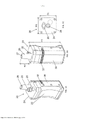
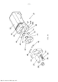
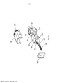
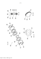
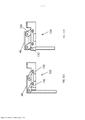
[0067] As Figuras 2A a B são vistas explodidas do vaporizador das Figuras 1A a C, de acordo com algumas aplicações da presente invenção;[0067] Figures 2A to B are exploded views of the vaporizer of Figures 1A to C, according to some applications of the present invention;
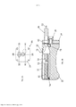
[0068] A Figura 3A é uma vista superior e as Figuras 3B a D são respectivas vistas em corte transversal do vaporizador das Figuras 1A a C, de acordo com algumas aplicações da presente invenção;[0068] Figure 3A is a top view and Figures 3B to D are respective cross-sectional views of the vaporizer of Figures 1A to C, in accordance with some applications of the present invention;
[0069] As Figuras 4A a D são ilustrações esquemáticas de respectivas vistas de uma cápsula que contém material vegetal que inclui um ingrediente ativo, de acordo com algumas aplicações da presente invenção;[0069] Figures 4A to D are schematic illustrations of respective views of a capsule containing plant material that includes an active ingredient, in accordance with some applications of the present invention;
[0070] A Figura 5 é uma ilustração esquemática dos eletrodos do vaporizador em contato com uma malha de uma cápsula que contém material vegetal que inclui um ingrediente ativo, de acordo com algumas aplicações da presente invenção;[0070] Figure 5 is a schematic illustration of vaporizer electrodes in contact with a mesh of a capsule containing plant material that includes an active ingredient, in accordance with some applications of the present invention;
[0071] As Figuras 6A a C são ilustrações esquemáticas de respectivas configurações dos eletrodos do vaporizador, de acordo com algumas aplicações da presente invenção;[0071] Figures 6A to C are schematic illustrations of the respective configurations of the vaporizer electrodes, according to some applications of the present invention;
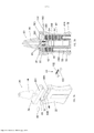
[0072] As Figuras 7A a B são uma ilustração esquemática de respectivas vistas de um vaporizador que inclui um mecanismo de transferência de cápsula linear, de acordo com algumas aplicações da presente invenção;[0072] Figures 7A to B are a schematic illustration of respective views of a vaporizer that includes a linear capsule transfer mechanism, in accordance with some applications of the present invention;
[0073] A Figura 8 é um gráfico que ilustra uma técnica para aquecer o material vegetal com o uso de um vaporizador, de acordo com algumas aplicações da presente invenção;[0073] Figure 8 is a graph illustrating a technique for heating plant material using a vaporizer, in accordance with some applications of the present invention;
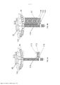
[0074] As Figuras 9A a C são ilustrações esquemáticas das porções de um vaporizador, de acordo com algumas aplicações da presente invenção;[0074] Figures 9A to C are schematic illustrations of portions of a vaporizer, according to some applications of the present invention;
[0075] A Figura 10A é uma ilustração esquemática de um eletrodo, de acordo com algumas aplicações da presente invenção;[0075] Figure 10A is a schematic illustration of an electrode, according to some applications of the present invention;
[0076] As Figuras 10B é uma ilustração esquemática de um mecanismo de movimento de eletrodo, de acordo com algumas aplicações da presente invenção;[0076] Figures 10B is a schematic illustration of an electrode movement mechanism, according to some applications of the present invention;
[0077] As Figuras 11A ou D são ilustrações esquemáticas de um mecanismo de movimento de eletrodo, de acordo com algumas aplicações da presente invenção;[0077] Figures 11A or D are schematic illustrations of an electrode movement mechanism, according to some applications of the present invention;
[0078] As Figuras 12A ou B são ilustrações esquemáticas de um mecanismo de movimento de eletrodo, de acordo com algumas aplicações da presente invenção;[0078] Figures 12A or B are schematic illustrations of an electrode movement mechanism, according to some applications of the present invention;
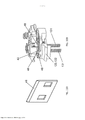
[0079] As Figuras 13A a C são ilustrações esquemáticas de um vaporizador que é configurado para extrair automaticamente uma dada dose volumétrica de um material vegetal a partir de uma massa do material vegetal que é disposta em um receptáculo do vaporizador, de acordo com algumas aplicações da presente invenção; e[0079] Figures 13A to C are schematic illustrations of a vaporizer that is configured to automatically extract a given volumetric dose of plant material from a mass of plant material that is disposed in a vaporizer receptacle, according to some applications. of the present invention; and
[0080] As Figuras 14A a C são ilustrações esquemáticas de um vaporizador que é configurado para extrair automaticamente uma dada dose volumétrica de um material vegetal a partir de uma massa do material vegetal que é disposta em um receptáculo do vaporizador, de acordo com algumas aplicações da presente invenção. DESCRIÇÃO DETALHADA DAS MODALIDADES[0080] Figures 14A to C are schematic illustrations of a vaporizer that is configured to automatically extract a given volumetric dose of plant material from a mass of plant material that is disposed in a vaporizer receptacle, according to some applications. of the present invention. DETAILED DESCRIPTION OF MODALITIES
[0081] Faz-se referência, agora, às Figuras 1A a C, que são ilustrações esquemáticas de respectivas vistas do exterior de um vaporizador 20, de acordo com algumas aplicações da presente invenção. Tipicamente, o vaporizador 20 é usado para vaporizar o ingrediente ativo de um material, como um material vegetal. Por exemplo, o vaporizador 20 pode ser usado para vaporizar os canabinoides constituintes de cannabis (por exemplo, tetra-hidrocanabinol (THC) e/ou canabidiol (CBD)). Alternativa ou adicionalmente, o vaporizador pode ser usado para vaporizar tabaco e/ou outras substâncias vegetais ou químicas que contêm um ingrediente ativo que se torna vaporizado na substância que é aquecida. Nota-se que algumas aplicações da presente invenção são descritas com referência a um material vegetal que contém um ingrediente ativo. No entanto, o escopo da presente invenção inclui usar qualquer substância que contenha um ingrediente ativo, após devidas alterações.[0081] Reference is now made to Figures 1A to C, which are schematic illustrations of respective exterior views of a
[0082] O vaporizador 20 inclui um corpo principal 22, que aloja cápsulas e conjunto de circuitos de controle do vaporizador, conforme descrito em mais detalhes no presente documento abaixo. O conjunto de circuitos de controle é configurado para agir como uma unidade de controle, que controla o funcionamento do vaporizador. Tipicamente, o vaporizador inclui adicionalmente uma cobertura superior 24, da qual um bocal 26 se projeta. Durante o uso, o usuário inala, tipicamente, o ingrediente ativo vaporizado por meio do bocal.[0082] The
[0083] Tipicamente, o vaporizador 20 é configurado para ser portátil e, durante o uso, o vaporizador é configurado para ser mantido em uma única mão de um usuário. As dimensões do vaporizador são tipicamente conforme segue:[0083] Typically, the
[0084] Uma altura H1 do corpo principal 22 do vaporizador (excluindo o bocal 26) é tipicamente mais de 8 cm (por exemplo, mais de 10 cm) e/ou menos de 15 cm (por exemplo, menos de 12 cm), por exemplo, entre 8 cm e 15 cm, ou entre 10 e 12 cm.[0084] A height H1 of the vaporizer main body 22 (excluding nozzle 26) is typically more than 8 cm (e.g. more than 10 cm) and/or less than 15 cm (e.g. less than 12 cm), for example, between 8 cm and 15 cm, or between 10 and 12 cm.
[0085] Uma altura H2 do bocal 26 é tipicamente mais de 2 cm (por exemplo, mais de 2,5 cm) e/ou menos de 6 cm (por exemplo, menos de 3,5 cm), por exemplo, entre 2 cm e 6 cm, ou entre 2,5 e 3,5 cm.[0085] A height H2 of
[0086] Tipicamente, a altura total do vaporizador, incluindo o bocal, é menor que 20 cm, por exemplo, menor que 15 cm.[0086] Typically, the total height of the vaporizer, including the mouthpiece, is less than 20 cm, for example, less than 15 cm.
[0087] Uma largura W1 do vaporizador é tipicamente mais de 3 cm (por exemplo, mais de 4 cm) e/ou menos de 9 cm (por exemplo, menos de 6 cm), por exemplo, entre 3 cm e 9 cm, ou entre 4 e 6 cm.[0087] A vaporizer width W1 is typically more than 3 cm (e.g. more than 4 cm) and/or less than 9 cm (e.g. less than 6 cm), e.g. between 3 cm and 9 cm, or between 4 and 6 cm.
[0088] Uma profundidade D1 do vaporizador é tipicamente mais de 2 cm (por exemplo, mais de 3 cm) e/ou menos de 6 cm (por exemplo, menos de 5 cm), por exemplo, entre 2 cm e 6 cm, ou entre 3 e 5 cm.[0088] A vaporizer depth D1 is typically more than 2 cm (e.g. more than 3 cm) and/or less than 6 cm (e.g. less than 5 cm), e.g. between 2 cm and 6 cm, or between 3 and 5 cm.
[0089] Para algumas aplicações, uma roda de transferência de cápsula 28 é disposta no lado de fora da cobertura superior. A roda de transferência de cápsula controla um mecanismo de transferência de cápsula 44 (Figura 2A). Conforme descrito em mais detalhes no presente documento abaixo, o mecanismo de transferência de cápsula é configurado para (a) transferir individualmente as cápsulas não usadas de um primeiro receptáculo 40A (Figura 2A) dentro do corpo principal do vaporizador para um local de vaporização 46 (Figura 2A), no qual a cápsula é aquecida como para vaporizar o ingrediente ativo, e (b) para transferir individualmente as cápsulas usadas a partir do local de vaporização para um segundo receptáculo 40B (Figura 2A) no corpo principal do vaporizador. Para algumas aplicações, o mecanismo de transferência de cápsula é um mecanismo giratório, por exemplo, um disco giratório, conforme mostrado na Figura 2A. Para algumas tais aplicações, a roda de transferência de cápsula é girada por um usuário a fim de controlar o mecanismo de transferência de cápsula giratório. Alternativa ou adicionalmente, o mecanismo de transferência de cápsula giratório (ou qualquer outro mecanismo de transferência de cápsula descrito no presente documento) é controlado por um motor elétrico (não mostrado).[0089] For some applications, a
[0090] Para algumas aplicações, uma cobertura traseira removível 30 é disposta no corpo principal 22 do vaporizador 20. Conforme mostrado, para algumas aplicações, a cobertura traseira define uma grade 32. A grade 32 é configurada para permitir o fluxo de ar para o corpo principal do vaporizador, conforme descrito em mais detalhes no presente documento abaixo.[0090] For some applications, a removable
[0091] Para algumas aplicações, a superfície interna do bocal 26 (e/ou outras porções do vaporizador) inclui um revestimento lipofóbico ou hidrofóbico 27 que é configurado para impedir que os produtos da vaporização do ingrediente ativo grudem na superfície interna do bocal. Alternativa ou adicionalmente, a carga elétrica é acionada para as superfícies do vaporizador (como a superfície interna do bocal 26), de modo que a carga se acumule nas superfícies e repele os produtos da vaporização do ingrediente ativo das superfícies.[0091] For some applications, the inner surface of the nozzle 26 (and/or other portions of the vaporizer) includes a lipophobic or
[0092] Faz-se referência, agora, às Figuras 2A a B, que são vistas explodidas do vaporizador 20, de acordo com algumas aplicações da presente invenção.[0092] Reference is now made to Figures 2A to B, which are exploded views of
[0093] Com referência à Figura 2A, tipicamente, o vaporizador 20 inclui o primeiro e o segundo receptáculos 40A e 40B, que são configurados para alojar cápsulas 42, que incluem um material vegetal que contém um ingrediente ativo. As cápsulas não usadas são tipicamente alojadas em uma configuração empilhada dentro do primeiro receptáculo, e as cápsulas usadas são alojadas em uma configuração empilhada dentro do segundo receptáculo.[0093] Referring to Figure 2A, typically, the
[0094] O mecanismo de transferência de cápsula 44 é configurado para transferir as cápsulas do primeiro receptáculo para o segundo receptáculo. Para algumas aplicações, o mecanismo de transferência de cápsula é um mecanismo de transferência de cápsula giratório (por exemplo, um disco giratório), conforme mostrado na Figura 2A. Tipicamente, o mecanismo de transferência de cápsula é configurado para (a) transferir individualmente as cápsulas não usadas do primeiro receptáculo 40A para o local de vaporização 46 em que a cápsula é aquecida como para vaporizar o ingrediente ativo, e (b) para transferir individualmente as cápsulas usadas do local de vaporização para o segundo receptáculo 40B.[0094]
[0095] Para algumas aplicações, o vaporizador 20 inclui um ou mais elementos de aquecimento, que são configurados para aquecer o material vegetal na cápsula (como para vaporizar o ingrediente ativo no material vegetal). Para algumas aplicações, os eletrodos 48 são configurados para agir como elementos de aquecimento, aquecendo-se o material vegetal dentro da cápsula, adicionando-se uma corrente elétrica para a cápsula 42. Para algumas aplicações, a cápsula 42 inclui uma ou mais malhas metálicas 84 (Figura 4A). Os eletrodos aquecem o material vegetal aquecendo-se a uma ou mais malhas por meio do aquecimento resistivo, acionando-se uma corrente para a uma ou mais malhas. Alternativa ou adicionalmente, os eletrodos aquecem um elemento de aquecimento interno que é alojado no vaporizador, acionando-se uma corrente para o elemento de aquecimento interno. Tipicamente, a corrente elétrica que é acionada é fixa, de modo que, por exemplo, o aquecimento das cápsulas não é afetado por variações no grau de contato entre os eletrodos e das malhas das cápsulas.[0095] For some applications, the
[0096] Para algumas aplicações, uma mola 49 com um elemento de pressionamento 51 é disposta sob uma porção 25 da cobertura superior 24. A mola é configurada para pressiona as cápsulas usadas no segundo receptáculo 40B.[0096] For some applications, a
[0097] Para algumas aplicações, uma porção da cápsula 42 é revestida ou preenchida com um material de alteração de fase 47. O material de alteração de fase é selecionado como para manter a cápsula abaixo da temperatura de pirólise do material vegetal e, desse modo, impede que o material vegetal seja pirolisado. Por exemplo, o material de alteração de fase pode ser submetido a uma alteração de fase de sólido para líquido em uma temperatura que está entre a temperatura de vaporização e a temperatura de pirólise do material vegetal, de modo que o material de alteração de fase absorva calor como calor latente de fusão nessa temperatura. Para algumas aplicações, uma porção do vaporizador (por exemplo, local de vaporização 46, receptáculo 40A e/ou receptáculo 40B) é revestido com material de alteração de fase 47.[0097] For some applications, a portion of the
[0098] Com referência, agora, à Figura 2B, tipicamente, um forneci mento de energia 50 (por exemplo, uma bateria) e conjunto de circuitos de controle 52 são alojados dentro do corpo principal do vaporizador 20. Tipicamente, a fonte de alimentação e/ou o conjunto de circuitos de controle são acoplados ao corpo principal do vaporizador por um elemento de acoplamento 53, como um adesivo, um parafuso, um clipe e/ou um pino. Para algumas aplicações, o conjunto de circuitos de controle é configurado para acionar uma corrente para a cápsula por meio de eletrodos 48, com o uso de energia fornecida pela fonte de alimentação.[0098] Referring now to Figure 2B, typically, a power supply 50 (e.g., a battery) and
[0099] Para algumas aplicações, a cobertura traseira 30 é removível e reutilizável, e o conjunto de circuitos de controle 52, o fornecimento de energia 50 e/ou o sensor de temperatura 54 são acoplados à cobertura traseira (por exemplo, ao ser alojado na cobertura traseira). Tipicamente, para tais aplicações, após todas as cápsulas no vaporizador terem sido vaporizadas, a cobertura traseira é removida, juntamente com os componentes que são acoplados à cobertura traseira. A cobertura traseira e os componentes são, então, transferidos e acoplados a um vaporizador diferente que inclui cápsulas não usadas.[0099] For some applications, the
[00100] Para algumas aplicações, o vaporizador 20 inclui um sensor de temperatura 54 que é configurado para medir uma indicação da temperatura do material vegetal que está sendo aquecido, por exemplo, medindo-se a temperatura da cápsula que está sendo aquecida. Por exemplo, o sensor de temperatura pode ser um sensor de temperatura óptico, como um sensor de temperatura infravermelho, que é configurado para medir a temperatura da cápsula sem entrar em contato com a cápsula. Dessa maneira, o sensor de temperatura infravermelho mede a temperatura da cápsula, sem afetar a temperatura da cápsula extraindo-se calor da cápsula. Para algumas aplicações, o sensor de temperatura é coberto com um revestimento lipofóbico ou hidrofóbico 56 que protege o sensor de temperatura contra produtos da vaporização que são depositados no sensor de temperatura. Para algumas aplicações, um sensor de temperatura diferente é usado. Por exemplo, o conjunto de circuitos de controle pode detectar a temperatura da cápsula detectando-se alterações na resistência de componentes da cápsula (por exemplo, malha 84 da cápsula) com o uso de eletrodos 48.[00100] For some applications, the
[00101] Conforme descrito no presente documento acima, tipicamente as cápsulas não usadas são alojadas dentro do primeiro receptáculo 40A e as cápsulas usadas são alojadas dentro do receptáculo 40B. Tipicamente, as molas 58 e os elementos de pressionamento 60 são acoplados a uma cobertura inferior 62 do vaporizador. As molas e os elementos de pressionamento são configurados para manter as configurações empilhadas das cápsulas dentro dos receptáculos empurrando-se as cápsulas par o topo do vaporizador.[00101] As described in the present document above, typically unused capsules are housed within the
[00102] Faz-se referência, agora, às Figuras 3A a D. As Figuras 3B a D são vistas em corte transversal esquemáticas do vaporizador 20, de acordo com algumas aplicações da presente invenção. A Figura 3A é uma vista superior do vaporizador 20, de acordo com algumas aplicações da presente invenção. A Figura 3A inclui linhas que indicam os locais das seções transversais que são mostradas, respectivamente, nas Figuras 3B, 3C e 3D.[00102] Reference is now made to Figures 3A to D. Figures 3B to D are schematic cross-sectional views of
[00103] Com referência à Figura 3B, para algumas aplicações, o vaporizador 20 inclui um vibrador 70 que é configurado para vibrar a cápsula 42, enquanto a cápsula está sendo aquecida. Durante o uso do vaporizador, o usuário inala por meio do bocal 26. Isso faz com que o ar flua através da grade 32 para o bocal por meio da cápsula, conforme indicado pelas setas de fluxo de ar 72. Devido ao aquecimento da cápsula o ingrediente ativo dentro do material vegetal da cápsula ser é vaporizado e é introduzido no ar que está fluindo através do vaporizador. Para algumas aplicações, vibrando-se a cápsula, o vibrador reduz o bloqueio de fluxo de ar através da cápsula e/ou aumenta o fluxo de ar através da cápsula em relação ao fato de se a cápsula não fosse vibrada. Para algumas aplicações, devido à vibração da cápsula, uma quantidade maior do ingrediente ativo vaporizar e entrar no fluxo de ar do que se a cápsula não fosse vibrada. Alternativa ou adicionalmente, a vibração da cápsula aprimora a distribuição de calor através da cápsula e/ou mistura o material vegetal na cápsula.[00103] Referring to Figure 3B, for some applications, the
[00104] De acordo com a respectiva aplicação, o vibrador 70 inclui um motor de vibração, um cristal piezoelétrico, um vibrador sônico, um vibrador ultrassônico e/ou um tipo diferente de vibrador. Para algumas aplicações, um ou mais parâmetros da vibração aplicada pelo vibrador é variada como para aumentar a eficiência da vaporização do ingrediente ativo, para aumentar o fluxo de ar através da cápsula, para reduzir o bloqueio de fluxo de ar, para aprimorar a distribuição de calor através da cápsula e/ou para misturar o material vegetal na cápsula. Por exemplo, a frequência, a amplitude e/ou a direção da vibração podem ser variadas.[00104] According to the respective application, the
[00105] Para algumas aplicações, o vaporizador 20 inclui uma porta 74 por meio da qual o vaporizador é conectado a uma fonte externa de energia e/ou entrada de dados. Por exemplo, o fornecimento de energia 50 pode ser configurado para ser recarregado conectando-se o vaporizador a uma fonte de alimentação externa por meio da porta 74. Alternativa ou adicionalmente, o conjunto de circuitos de controle 52 pode receber dados, por exemplo, instruções de programação, por meio da porta 74.[00105] For some applications, the
[00106] Para algumas aplicações, um profissional da área de saúde (por exemplo, um farmacêutico ou um médico) pode inserir instruções no conjunto de circuitos de controle que controla a taxa de aquecimento que é aplicada a uma dada quantidade de fluxo de ar através da cápsula. Controlando-se a taxa de aquecimento por unidade de fluxo de ar, a quantidade do ingrediente ativo que é vaporizado por unidade de fluxo de ar através do vaporizador pode ser controlada. Alternativa ou adicionalmente, o profissional da área de saúde pode inserir instruções no conjunto de circuitos de controle que controla a quantidade de fluxo de ar através do vaporizador que é permitido durante cada uso do vaporizador e/ou a quantidade de fluxo de ar através do vaporizador que é permitida em um dado período de tempo (por exemplo, por hora ou por dia). Dessa maneira, o profissional da área da saúde pode controlar a dosagem do ingrediente ativo que o usuário é capaz de receber durante casa uso do vaporizador, e/ou no dado período de tempo. Para algumas aplicações, o conjunto de circuitos de controle é configurado para determinar automaticamente a taxa e/ou o volume do fluxo de ar através do vaporizador, conforme descrito em mais detalhes no presente documento abaixo.[00106] For some applications, a healthcare professional (e.g., a pharmacist or a physician) may enter instructions into the control circuitry that controls the rate of heating that is applied to a given amount of airflow through of the capsule. By controlling the rate of heating per unit of airflow, the amount of active ingredient that is vaporized per unit of airflow through the vaporizer can be controlled. Alternatively or additionally, the healthcare professional may enter instructions into the control circuitry that controls the amount of airflow through the vaporizer that is allowed during each use of the vaporizer and/or the amount of airflow through the vaporizer. that is allowed in a given period of time (for example, per hour or per day). In this way, the healthcare professional can control the dosage of active ingredient that the user is able to receive during each use of the vaporizer, and/or in the given period of time. For some applications, the control circuitry is configured to automatically determine the rate and/or volume of airflow through the vaporizer, as described in more detail in this document below.
[00107] Com referência, agora, à Figura 3C, conforme mostrado, as cápsulas 42 que não são usadas (isto é, cápsulas, o ingrediente ativo do material vegetal das quais o mesmo não foi vaporizado) são alojadas, em uma configuração empilhada (isto é, de modo que quando o vaporizador estiver em uma orientação vertical, as cápsulas são dispostas uma acima da outra), dentro do receptáculo 40A. As cápsulas usadas são alojadas, em uma configuração empilhada, dentro do receptáculo 40B. Conforme descrito no presente documento acima, para algumas aplicações, as molas 58 e os elementos de pressiona- mento 60 são acoplados a uma cobertura inferior 62 do vaporizador e são configurados para manter as configurações empilhadas das cápsulas dentro dos receptáculos empurrando-se as cápsulas para o topo do vaporizador. Para algumas aplicações, armazenando-se as cápsulas em configurações empilhadas, as dimensões da largura e da profundidade do vaporizador 20 podem ser tais que o vaporizador pode ser segurado confortavelmente por um usuário (por exemplo, em uma única mão do usuário).[00107] Referring now to Figure 3C, as shown,
[00108] A mola 49 e o elemento de pressionamento 51 tipicamente empurram as cápsulas usadas para o receptáculo 40B, de modo que as cápsulas usadas sejam mantidas abaixo de um plano de movimento do mecanismo de transferência de cápsula 44. Dessa maneira, as cápsulas que foram colocadas dentro do receptáculo 40B permanecem dentro do receptáculo 40B, mesmo quando o mecanismo de transferência de cápsula é movido.[00108]
[00109] Para algumas aplicações, as cápsulas 42 têm cortes transversais circulares, e os receptáculos 40A e 40B definem tubos cilíndricos que alojam as cápsulas. Alternativamente, as cápsulas 42 podem ter um formato diferente, e os receptáculos 40A e 40B podem definir espaços ocos que são configurados de modo a se conformar com os formados das cápsulas.[00109] For some applications, the
[00110] Com referência à Figura 3D, conforme descrito no presente documento acima, para algumas aplicações, o sensor de temperatura 54 é um sensor de temperatura óptico, como um sensor de temperatura infravermelho, que é configurado para medir a temperatura da cápsula sem entrar em contato com a cápsula. A Figura 3D mostra o sensor 54 que recebe feixes 80 de luz óptica da cápsula 42, sendo que a cápsula foi aquecida. O sensor 54 é configurado para medir a temperatura da cápsula 42, com base na luz recebida.[00110] Referring to Figure 3D, as described in the present document above, for some applications, the
[00111] Conforme mostrado na Figura 3D, para algumas aplicações, o eletrodo 48 inclui pelo menos quatro eletrodos 48A, 48B, 48C e 48D. O material vegetal contido dentro da cápsula é aquecido acionando-se uma corrente do primeiro eletrodo 48A para o segundo eletrodo 48B por meio de uma malha inferior da cápsula 42. Alternativa ou adicionalmente, o material vegetal contido na cápsula é aquecido acionando-se uma corrente do terceiro eletrodo 48C para o quarto eletrodo 48D por meio de uma malha superior da cápsula 42. Para algumas aplicações, aquecendo-se o material vegetal da maneira mencionada anteriormente, o material vegetal dentro da cápsula é aquecido mais uniformemente do que se, por exemplo, um eletrodo monopolar tivesse que acionar uma corrente para um local na malha superior ou inferior. Para algumas aplicações, a cápsula 42 inclui um elemento de aquecimento interno (por exemplo, uma malha interna (não mostrada)), como uma alternativa ou adicionalmente às malhas superior e inferior. O elemento de aquecimento interno é configurado para ser aquecido de uma maneira semelhante àquela descrita com referência às malhas superior e inferior.[00111] As shown in Figure 3D, for some applications,
[00112] Faz-se referência, agora, às Figuras 4A a D, que são ilustrações esquemáticas de respectivas vistas da cápsula 42, a cápsula contendo material vegetal 82 que inclui um ingrediente ativo, de acordo com algumas aplicações da presente invenção. Conforme descrito no presente documento acima, para algumas aplicações, o material vegetal é cannabis, e o ingrediente ativo são os canabinoides constituintes de cannabis (por exemplo, tetra-hidrocanabinol (THC) e/ou canabidiol (CBD)). Alternativa ou adicionalmente, o material vegetal pode ser tabaco e/ou outras substâncias vegetais ou químicas que contêm um ingrediente ativo que se torne vaporizado mediante ao fato de a substância ser aquecida.[00112] Reference is now made to Figures 4A to D, which are schematic illustrations of respective views of the
[00113] Para algumas aplicações, o material vegetal 82 é alojado entre as malhas metálicas superior e inferior 84. Para algumas aplicações, cada uma das malhas tem aberturas de mais de 15 mícron (por exemplo, mais de 20 mícrones) e/ou menos de 80 mícron (por exemplo, menos de 50 mícron), por exemplo, de 15 a 60 mícron ou de 20 a 50 mícron. Tipicamente, as malhas são acopladas a uma porção central 86 da cápsula (por exemplo, um disco central, conforme mostrado), a porção central que define um orifício. Por exemplo, as malhas podem ser acopladas à porção central por meio de um adesivo 88, como uma cola resistente a alta temperatura, ou adesivo dupla face. Tipicamente, o adesivo é configurado de modo que o adesivo não emita fumos, mesmo quando o adesivo for submetido a uma alta temperatura, como uma temperatura maior que 200 graus Celsius. Tipicamente, o material vegetal é alojado entre as malhas e dentro do orifício definido pela porção central da cápsula.[00113] For some applications, the
[00114] Tipicamente, o material vegetal 82 é triturado, de modo que (a) o material vegetal esteja em pedaços suficientemente pequenos para que o material se encaixe na cápsula, e uma área de superfície grande do material vegetal é exposta ao fluxo de ar através do vaporizador (b) os pedaços do material vegetal sejam suficientemente grandes para que não passem através das malhas, e (c) o ingrediente ativo retenha sua potência. Para algumas aplicações, o material vegetal é criogenicamente triturado e/ou transformado em pó.[00114] Typically, the
[00115] Para algumas aplicações, os elementos de espaçamento 90 são acoplados ao lado de fora de uma ou ambas as malhas. Os elementos de espaçamento são configurados de modo que, quando as cápsulas forem dispostas na configuração empilhada dentro do vaporizador, há um espaço entre a malha superior de uma cápsula e a malha inferior da cápsula adjacente. Os elementos de espaçamento são configurados como para realizar a função mencionada anteriormente sem bloquear o fluxo de ar através das malhas e/ou do material vegetal, e sem interferir com o contato entre os eletrodos 48 e as malhas 84. Para algumas aplicações, o elemento de espaçamento é uma fita adesiva de única face. Para algumas aplicações, um material de revestimento antiadesivo é usado como o elemento de espaçamento. O material de revestimento antiadesivo é configurado para impedir que as cápsulas não usadas fiquem presas umas às outras quando as cápsulas não usadas forem alojadas no receptáculo 40A.[00115] For some applications, the
[00116] Para algumas aplicações, a porção central 86 da cápsula 42 é produzida a partir de um material que tem uma alta capacidade térmica e/ou baixa condutividade térmica para que isso reduza a perda de calor da cápsula para a área circundante e reduza o aquecimento da área circundante durante o processo de evaporação. Para algumas aplicações, pelo menos um dos fios das malhas 84 é oco, e um material de alteração de fase é disposto dentro do fio oco. O material de alteração de fase reduz a perda de calor da cápsula, fazendo-se com que a cápsula absorva, de preferência, o calor em relação às áreas ao redor da cápsula. Alternativa ou adicionalmente, um material de alteração de fase é acoplado à cápsula de uma maneira diferente, por exemplo, revestindo-se a cápsula. Conforme descrito no presente documento acima, tipicamente, o material de alteração de fase é selecionado como para manter a cápsula abaixo da temperatura de pirólise do material vegetal, e para, desse modo, impedir que o material vegetal seja pirolisado.[00116] For some applications, the
[00117] Faz-se referência, agora, à Figura 5, que é uma ilustração esquemática de eletrodos 48 de vaporizador 20 em contato com malhas 84 da cápsula 42, de acordo com algumas aplicações da presente invenção. Conforme mostrado, os eletrodos 48 fazem contato com as malhas mesmo quando os elementos de espaçamento 90 são dispostos nos lados de fora das malhas.[00117] Reference is now made to Figure 5, which is a schematic illustration of
[00118] Faz-se referência, agora, às Figuras 6A a D, que são ilustrações esquemáticas de respectivas configurações de eletrodos 48 do vaporizador 20, de acordo com algumas aplicações da presente invenção. A Figura 6A mostra exemplos de eletrodos 48A e 48B, de acordo com algumas aplicações da presente invenção. Conforme mostrado, para algumas aplicações, uma superfície 92 do eletrodo age como um contato elétrico, por meio do qual o contato elétrico é feito com uma malha da cápsula. As Figuras 6B a 6D mostram exemplos de eletrodo 48B, de acordo com as respectivas aplicações da presente invenção. Para algumas aplicações, os eletrodos incluem contatos 94 que se projetam a partir da superfície 92 do eletrodo. Conforme mostrado, o contato pode ser configurado como uma placa plana (Figura 6B), ou como uma pluralidade de pontos, por exemplo, dois pontos (Figura 6C), ou três pontos (Figura 3D).[00118] Reference is now made to Figures 6A to D, which are schematic illustrations of respective configurations of
[00119] Faz-se referência, agora, às Figuras 7A a B, que são ilustrações esquemáticas de respectivas vistas de vaporizador 20, o mecanismo de transferência de cápsula 44 do vaporizador que é um mecanismo linear, de acordo com algumas aplicações da presente invenção.[00119] Reference is now made to Figures 7A to B, which are schematic illustrations of respective views of
[00120] Conforme mostrado nas Figuras 7A a B, de acordo com algumas aplicações, as cápsulas 42 são conformadas em um formato que não é circular. Por exemplo, conforme mostrado nas Figuras 7A a B, a cápsula pode ter um corte transversal em formato de pista de corrida. Para tais aplicações, os receptáculos 40A e 40B definem espaços ocos que são configurados de modo a se conformarem ao formato das cápsulas.[00120] As shown in Figures 7A to B, according to some applications, the
[00121] Para algumas aplicações, o topo do receptáculo 40A, o topo do receptáculo 40B e o local de vaporização, no qual as cápsulas são aquecidas, são alinhadas entre si (por exemplo, através da largura do vaporizador, conforme mostrado nas Figuras 7A a B). Um mecanismo de transferência de cápsula linear 44 é configurado para empurrar as cápsulas não usadas do receptáculo 40A para o local de vaporização 46 no qual a cápsula é aquecida, e do local de vaporização para o segundo receptáculo 40B. Para algumas aplicações, o mecanismo de transferência de cápsula linear inclui um empurrador 100 que é configurado para transferir as cápsulas da maneira acima descrita, pelo empurrador que é empurrado axialmente em uma dada direção. Para algumas aplicações, uma mola 102 é acoplada ao empurrador, sendo que a mola é configurada para aplicar uma força ao empurrador que opõe o movimento do empurrador na dada direção.[00121] For some applications, the top of the
[00122] Com referência à Figura 7B, para algumas aplicações, uma bomba 200 (mostrada esquematicamente na Figura 7B) é usada para controlar o fluxo de ar através do vaporizador. Para algumas aplicações, o vaporizador é configurado para definir um canal de fluxo de ar complementar 201, que fornece fluxo de ar para fora do bocal, mas não por meio da cápsula que é vaporizada. Dessa maneira, em resposta a uma grande inalação pelo usuário, o vaporizador tem capacidade de fornecer ar ao usuário, sem aumentar a dosagem do ingrediente ativo que é fornecida para o usuário. Para algumas aplicações, uma válvula 203 (mostrada esquematicamente na Figura 7B) é disposta dentro do canal de fluxo de ar complementar e é configurada para controlar o fluxo de ar através do canal de fluxo de ar complementar.[00122] Referring to Figure 7B, for some applications, a pump 200 (shown schematically in Figure 7B) is used to control the flow of air through the vaporizer. For some applications, the vaporizer is configured to define a
[00123] Para algumas aplicações, o vaporizador 20 inclui um fluxo de ar sensor, por exemplo, uma válvula 202(mostrada esquematicamente na Figura 7B). A válvula é configurada para medir o fluxo de ar através do vaporizador. Para algumas aplicações, o fluxo de ar medido é recebido como uma entrada para o conjunto de circuitos de controle, e o conjunto de circuitos de controle varia como um parâmetro do aquecimento em resposta ao fluxo de ar detectado.[00123] For some applications, the
[00124] Com exceção das diferenças descritas nos parágrafos acima, o vaporizador 20 e as porções do mesmo mostradas nas Figuras 7A a B são, geralmente, semelhantes ao vaporizador e as porções do mesmo descritos com referência às Figuras 1A a 6D. O escopo da presente invenção inclui combinar recursos do vaporizador e porções dos mesmos descritos com referência às Figuras 7A a B, com os recursos do vaporizador e as porções do mesmo descritos com referência às Figuras 1A a 6D, e vice-versa.[00124] With the exception of the differences described in the paragraphs above, the
[00125] Faz-se referência, agora, à Figura 8, que é um gráfico que ilustra as respectivas técnicas para aquecer o material vegetal com o uso de um vaporizador, como vaporizador 20, de acordo com algumas aplicações da presente invenção. O eixo geométrico x do gráfico indica tempo (medido em segundos), e o eixo geométrico y indica a temperatura (medida em graus Celsius) de uma cápsula que contém um material vegetal (e, portanto, indica a temperatura do material vegetal na cápsula), conforme descrito no presente documento.[00125] Reference is now made to Figure 8, which is a graph illustrating respective techniques for heating plant material using a vaporizer, such as
[00126] Conforme descrito no presente documento acima, para algumas aplicações, o vaporizador 20 é usado para vaporizar ingredientes ativos na cannabis. Cannabis tem, tipicamente, uma temperatura de vaporização de 180 graus Celsius, e começa a se tornar pirolisado a 220 graus Celsius. Portanto, é tipicamente desejável aquecer a cannabis até uma temperatura entre 190 graus Celsius e 210 graus Celsius. As delimitações superior e inferior da faixa de temperatura desejada às quais para aquecer cannabis são denotados no gráfico da Figura 8, por duas linhas horizontais sólidas a 190 graus Celsius e 210 graus Celsius. Adicionalmente de modo típico, é desejável não aquecer a cannabis até uma temperatura que é maior que a temperatura descrita, a fim de impedir a pirólise da cannabis. Tipicamente, quando o vaporizador for usado com materiais vegetais além de cannabis, considerações semelhantes são aplicáveis, embora a temperatura desejada até a qual o material vegetal deve ser aquecido irá variar dependendo das características do material vegetal que está sendo usado com o vaporizador.[00126] As described in the present document above, for some applications the
[00127] Um modo possível de aquecer o material vegetal até a temperatura desejada é por meio de aquecimento gradual, conforme denotado pela linha diagonal tracejada, que mostra o material vegetal que é aquecido até a temperatura desejada em um período de mais de 8 segundos. Um outro modo possível de aquecer o material vegetal é por meio de aquecimento rápido, conforme denotado pela curva pontilhada na Figura 8. Tipicamente, se o material vegetal for aquecido rapidamente, então, inicialmente há um excesso na temperatura até a qual o material vegetal é aquecido. Por exemplo, isso se deve ao fato de que há um intervalo entre quando o material vegetal chega à temperatura desejada e quando o conjunto de circuitos de controle detecta que a temperatura desejada foi obtida e impede o aumento adicional de temperatura do material vegetal em resposta à temperatura detectada. Isso é indicado na Figura 8, que mostra que a curva pontilhada sobe inicialmente acima de 220 graus Celsius, antes de chegar ao platô na faixa de temperatura desejada. Devido ao excesso, uma parte do material vegetal pode se tornar pirolisada.[00127] One possible way to heat plant material to the desired temperature is through gradual heating, as denoted by the dashed diagonal line, which shows plant material being heated to the desired temperature over a period of more than 8 seconds. Another possible way of heating plant material is through rapid heating, as denoted by the dotted curve in Figure 8. Typically, if plant material is heated rapidly, then initially there is an excess in temperature to which the plant material is heated. heated. For example, this is due to the fact that there is a gap between when the plant material reaches the desired temperature and when the control circuitry detects that the desired temperature has been achieved and prevents the plant material from further increasing the temperature in response to the change. temperature detected. This is indicated in Figure 8, which shows that the dotted curve initially rises above 220 degrees Celsius, before reaching the plateau in the desired temperature range. Due to excess, some of the plant material can become pyrolyzed.
[00128] De acordo com algumas aplicações da presente invenção, um processo de aquecimento de dois estágios é aplicado ao material vegetal dentro de um vaporizador, por exemplo, conforme indicado pela curva sólida mostrada na Figura 8. Tipicamente, em resposta ao recebimento de uma primeira entrada no vaporizador (por exemplo, em resposta ao pressionamento do usuário de um comutador ativado no vaporizador), o conjunto de circuitos de controle do vaporizador inicia uma primeira etapa de aquecimento. Tipicamente, a primeira etapa de aquecimento é uma etapa de aquecimento rápido (por exemplo, uma etapa de aquecimento em que a cápsula que contém o material vegetal é aquecida em uma taxa de mais de 50 graus Celsius por segundo, ou mais de 100 graus Celsius por segundo). Adicionalmente de modo típico, o conjunto de circuitos de controle do vaporizador é configurado para terminar a primeira etapa de aquecimento, impedindo-se o aumento adicional da temperatura da cápsula, em resposta à detecção de que a temperatura da cápsula (que é indicativa da temperatura do material vegetal) chegou a uma primeira temperatura. Tipicamente, a primeira temperatura é menor que 95 %, por exemplo, menor que 90 %, ou menor que 80 %, da temperatura de vaporização do material vegetal. Por exemplo, quando o vaporizador é usado para vaporizar a cannabis, o conjunto de circuitos de controle do vaporizador pode ser configurado para impedir o aumento adicional da temperatura da cápsula, em resposta à detecção de que a temperatura da cápsula chegou a uma primeira temperatura que é menor que 170 graus Celsius (por exemplo, menor que 160 graus Celsius), por exemplo, uma temperatura que é entre 140 e 170 graus Celsius, ou entre 150 e 160 graus Celsius.[00128] In accordance with some applications of the present invention, a two-stage heating process is applied to plant material within a vaporizer, for example, as indicated by the solid curve shown in Figure 8. Typically, in response to receiving a first entry into the vaporizer (for example, in response to the user pressing an activated switch on the vaporizer), the vaporizer control circuitry initiates a first heating step. Typically, the first heating step is a rapid heating step (e.g. a heating step in which the capsule containing the plant material is heated at a rate of over 50 degrees Celsius per second, or over 100 degrees Celsius per second). Additionally, typically, the vaporizer control circuitry is configured to terminate the first heating step, preventing the capsule temperature from increasing further in response to detection that the capsule temperature (which is indicative of the of plant material) has reached a first temperature. Typically, the first temperature is less than 95%, for example less than 90%, or less than 80%, of the vaporization temperature of the plant material. For example, when the vaporizer is used to vaporize cannabis, the vaporizer's control circuitry can be configured to prevent the capsule temperature from rising further in response to the detection that the capsule temperature has reached a first temperature that is less than 170 degrees Celsius (for example, less than 160 degrees Celsius), for example a temperature that is between 140 and 170 degrees Celsius, or between 150 and 160 degrees Celsius.
[00129] Configurando-se o conjunto de circuitos de controle para terminar o primeiro estágio de aquecimento rápido conforme descrito, mesmo se houver excesso, e a temperatura da cápsula sobe acima da temperatura em que o primeiro estágio de aquecimento foi programado para ser terminado, a temperatura da cápsula não irá, tipicamente, subir acima da temperatura de pirólise do material vegetal. Por exemplo, conforme mostrado na Figura 8, o conjunto de circuitos de controle foi configurado para impedir o aumento adicional da temperatura da cápsula em resposta à detecção de que a temperatura da cápsula chegou aproximadamente à 160 graus Celsius. Inicialmente (em aproximadamente 0,5 segundo), há um excesso, e a temperatura da cápsula chega aproximadamente a 180 graus Celsius. No entanto, a temperatura da cápsula chega, então, a um platô de aproximadamente 160 graus Celsius, em cerca de 1 segundo. Para algumas aplicações, o conjunto de circuitos de controle do vaporizador gera uma saída para o usuário para indicar que o primeiro estágio do aquecimento terminou. Por exemplo, o conjunto de circuitos de controle pode iluminar uma luz indicadora, pode fazer com que o vaporizador vibre, e/ou pode emitir um sinal de áudio (por exemplo, um bipe).[00129] By configuring the control circuitry to terminate the first stage of rapid heating as described, even if there is excess, and the capsule temperature rises above the temperature at which the first stage of heating was programmed to terminate, the temperature of the capsule will typically not rise above the pyrolysis temperature of the plant material. For example, as shown in Figure 8, the control circuitry has been configured to prevent the capsule temperature from increasing further in response to the detection that the capsule temperature has reached approximately 160 degrees Celsius. Initially (in approximately 0.5 second) there is an overflow, and the temperature of the capsule reaches approximately 180 degrees Celsius. However, the capsule temperature then reaches a plateau of approximately 160 degrees Celsius in about 1 second. For some applications, the vaporizer's control circuitry generates an output to the user to indicate that the first stage of heating has ended. For example, the control circuitry may illuminate an indicator light, may cause the vaporizer to vibrate, and/or may emit an audio signal (e.g., a beep).
[00130] Subsequentemente, em resposta a uma segunda entrada para o vaporizador, o conjunto de circuitos de controle do vaporizador inicia uma segunda etapa de aquecimento (mostrada, na curva sólida na Figura 8, para começar em aproximadamente 3 segundos). Tipicamente, entre a extremidade do primeiro estágio do processo de aquecimento, e a iniciação do segundo estágio do processo de aquecimento, o conjunto de circuitos de controle mantém a temperatura da cápsula na primeira temperatura. Para algumas aplicações, o segundo estágio do aquecimento é iniciado automaticamente em resposta à inalação de ar do vaporizador por um usuário. Alternativamente, o segundo estágio do processo de aquecimento pode ser iniciado em resposta a uma entrada diferente pelo usuário (por exemplo, o usuário que pressiona o botão ligado pela segunda vez).[00130] Subsequently, in response to a second input to the vaporizer, the vaporizer control circuitry initiates a second heating step (shown, in solid curve in Figure 8, to start in approximately 3 seconds). Typically, between the end of the first stage of the heating process, and the initiation of the second stage of the heating process, the control circuitry maintains the temperature of the capsule at the first temperature. For some applications, the second stage of heating is automatically initiated in response to a user inhaling air from the vaporizer. Alternatively, the second stage of the heating process can be initiated in response to a different input by the user (eg the user pressing the power button a second time).
[00131] Durante a segunda etapa de aquecimento, o conjunto de circuitos de controle aquece tipicamente a cápsula em uma taxa mais lenta do que durante o primeiro estágio do processo de aquecimento. Por exemplo, durante o segundo estágio do processo de aquecimento, as malhas das cápsulas do vaporizador podem ser aquecidas em uma taxa menor que 50 graus Celsius por segundo, por exemplo, menor que 40 graus Celsius por segundo. Conforme mostrado na Figura 8, durante o estágio do processo de aquecimento (de 3 segundos a 5 segundos) a cápsula é aquecida de aproximadamente 160 graus Celsius a 200 graus Celsius.[00131] During the second stage of heating, the control circuitry typically heats the capsule at a slower rate than during the first stage of the heating process. For example, during the second stage of the heating process, the vaporizer pod meshes can be heated at a rate of less than 50 degrees Celsius per second, for example, less than 40 degrees Celsius per second. As shown in Figure 8, during the heating process stage (from 3 seconds to 5 seconds) the capsule is heated from approximately 160 degrees Celsius to 200 degrees Celsius.
[00132] No segundo estágio do processo de aquecimento, o conjunto de circuitos de controle é configurado para impedir o aumento adicional de temperatura da cápsula em resposta à detecção de que a temperatura da cápsula está entre a temperatura de vaporização do material vegetal e a temperatura de pirólise do material vegetal. Por exemplo, quando o vaporizador for usado para vaporizar a cannabis, o conjunto de circuitos de controle do vaporizador é configurado para impedir o aumento adicional de temperatura da cápsula, em resposta à detecção de que a temperatura da cápsula chegou a uma segunda temperatura que é mais de 180 graus Celsius (por exemplo, mais de 190 graus Celsius), e/ou menos de 220 graus Celsius (por exemplo, menos de 210 graus Celsius), por exemplo, uma temperatura que está entre 180 e 220 graus Celsius, ou entre 190 e 210 graus Celsius.[00132] In the second stage of the heating process, the control circuitry is configured to prevent further temperature rise of the capsule in response to the detection that the temperature of the capsule is between the vaporization temperature of the plant material and the temperature pyrolysis of plant material. For example, when the vaporizer is used to vaporize cannabis, the vaporizer's control circuitry is configured to prevent the capsule from rising further in temperature in response to the detection that the capsule temperature has reached a second temperature which is more than 180 degrees Celsius (for example, more than 190 degrees Celsius), and/or less than 220 degrees Celsius (for example, less than 210 degrees Celsius), for example, a temperature that is between 180 and 220 degrees Celsius, or between 190 and 210 degrees Celsius.
[00133] Para algumas aplicações, realizando-se o aquecimento no processo de dois estágios descrito no presente documento acima, um ou mais dos resultados a seguir são obtidos: 1) Terminando-se o primeiro (rápido) estágio do aquecimento em resposta à temperatura da cápsula que chega a menos que 95 % da temperatura de vaporização, mesmo se o aquecimento exceder, o material vegetal não é pirolisado, uma vez que o material vegetal não é aquecido até uma temperatura que é maior que a temperatura de pirólise. 2) Uma vez que o segundo estágio do aquecimento é realizado lentamente, há excesso desprezível no segundo estágio do processo de aquecimento e, portanto, o material vegetal não fica pirolisado no segundo estágio do processo de aquecimento. 3) Uma vez que, durante o primeiro estágio do aquecimento, o material vegetal já foi aquecido até uma temperatura que é relativamente próxima da temperatura de vaporização, muito embora o segundo estágio do aquecimento seja lento, o tempo que é necessário para aquecer o material vegetal até a temperatura de vaporização, da iniciação do segundo estágio de aquecimento, é relativamente curto (por exemplo, menos de dois segundos). 4) Devido à baixa condução de calor do material vegetal, se o material vegetal for rapidamente aquecido, isso pode originar o aquecimento não uniforme do material vegetal. Isso pode fazer com que as porções do material vegetal que estão próximas do elemento (ou elementos) de aquecimento (por exemplo, o eletrodo (ou eletrodos) sejam pirolisados e/ou as porções do material vegetal que são adicionais ao elemento (ou elementos) de aquecimento não sejam vaporizadas. Impedindo-se o aquecimento adicional do material vegetal após a primeira temperatura ter sido alcançada, e até que a segunda entrada seja recebida, o calor tem capacidade de se dissipar através do material vegetal (durante o período de ínterim entre o primeiro e o segundo estágios de aquecimento) antes de qualquer porção do material vegetal ter sido aquecida até a temperatura de vaporização. Ademais, uma vez que o aumento de temperatura durante o segundo estágio é relativamente pequeno, o aumento de temperatura tem capacidade de se dissipar através do material vegetal de modo relativamente rápido. Desse modo, o aquecimento uniforme do material vegetal é obtido, de modo que a maior parte do ingrediente ativo no material vegetal é vaporizado, enquanto não há substancialmente pirólise do material vegetal.[00133] For some applications, by performing the heating in the two-stage process described in the present document above, one or more of the following results are obtained: 1) Terminating the first (rapid) stage of heating in response to temperature of the capsule reaching less than 95% of the vaporization temperature, even if heating exceeds, the plant material is not pyrolyzed, since the plant material is not heated to a temperature that is greater than the pyrolysis temperature. 2) Since the second stage of heating is carried out slowly, there is negligible excess in the second stage of the heating process and therefore the plant material is not pyrolyzed in the second stage of the heating process. 3) Since, during the first stage of heating, the plant material has already been heated to a temperature that is relatively close to the vaporization temperature, even though the second stage of heating is slow, the time it takes to heat the material until the vaporization temperature, from the initiation of the second heating stage, is relatively short (e.g. less than two seconds). 4) Due to the low heat conduction of the plant material, if the plant material is heated quickly, it may lead to non-uniform heating of the plant material. This can cause portions of plant material that are close to the heating element (or elements) (e.g. the electrode (or electrodes) to be pyrolyzed and/or portions of plant material that are additional to the element (or elements)). by preventing further heating of the plant material after the first temperature has been reached, and until the second input is received, the heat is able to dissipate through the plant material (during the interim period between the first and second heating stages) before any portion of the plant material has been heated to vaporization temperature. Furthermore, since the temperature rise during the second stage is relatively small, the temperature rise is able to dissipate through the plant material relatively quickly. In this way, uniform heating of the plant material is achieved, so that most of the ingredient active substance in the plant material is vaporized, while there is substantially no pyrolysis of the plant material.
[00134] Para algumas aplicações, a inalação do vaporizador pelo usuário é automaticamente detectada pelo conjunto de circuitos de controle. Após o primeiro estágio do aquecimento, há tipicamente uma grande diferença entre a temperatura ambiente e a temperatura da cápsula que contém o material vegetal. Conforme descrito no presente documento acima, entre a extremidade do primeiro estágio do processo de aquecimento, e a iniciação do segundo estágio do processo de aquecimento, o conjunto de circuitos de controle mantém a temperatura da cápsula na primeira temperatura. Uma vez que há uma grande diferença entre a temperatura ambiente e a temperatura da cápsula, a energia que é necessária para manter a cápsula (e o material vegetal na mesma) em uma temperatura constante é maior quando o usuário estiver inalando do vaporizador do que quando o usuário não estiver inalando. Portanto, para algumas aplicações, o conjunto de circuitos de controle detecta que o usuário está inalando do vaporizador detectandose uma indicação de uma quantidade de energia que é necessária para manter constante a temperatura da cápsula (e o material vegetal na mesma). Por exemplo, o conjunto de circuitos de controle pode detectar variações no ciclo de trabalho que é usado para aquecer a cápsula (e o material vegetal na mesma). Alternativa ou adicionalmente, o conjunto de circuitos de controle pode detectar automaticamente que o usuário está inalando do vaporizador detectando-se diretamente a temperatura da cápsula. Uma vez que, após o primeiro estágio do aquecimento, há uma grande diferença entre a temperatura ambiente e a temperatura da cápsula, o fluxo de ar através da cápsula pode fazer com que uma alteração mensurável na temperatura da cápsula. Conforme descrito no presente documento acima, para algumas aplicações, o segundo estágio do processo de aquecimento é iniciado automaticamente em resposta à detecção de inalação do vaporizador pelo usuário.[00134] For some applications, inhalation of the vaporizer by the user is automatically detected by the control circuitry. After the first stage of heating, there is typically a large difference between the ambient temperature and the temperature of the capsule containing the plant material. As described in the present document above, between the end of the first stage of the heating process, and the initiation of the second stage of the heating process, the control circuitry maintains the temperature of the capsule at the first temperature. Since there is a big difference between room temperature and capsule temperature, the energy that is required to keep the capsule (and the plant material in it) at a constant temperature is greater when the user is inhaling from the vaporizer than when the user is not inhaling. Therefore, for some applications, the control circuitry detects that the user is inhaling from the vaporizer by detecting an indication of an amount of energy that is required to maintain a constant temperature of the capsule (and the plant material in it). For example, the control circuitry can detect variations in the duty cycle that is used to heat the capsule (and the plant material in it). Alternatively or additionally, the control circuitry can automatically detect that the user is inhaling from the vaporizer by directly sensing the capsule temperature. Since, after the first stage of heating, there is a large difference between the ambient temperature and the capsule temperature, the flow of air through the capsule can cause a measurable change in the temperature of the capsule. As described in the present document above, for some applications, the second stage of the heating process is automatically initiated in response to the user's detection of inhalation from the vaporizer.
[00135] Com o uso de uma técnica geralmente semelhante àquela descrita no presente documento acima, para algumas aplicações, o conjunto de circuitos de controle detecta uma taxa e/ou volume de fluxo de ar através do vaporizador, detectando-se uma indicação de uma quantidade de energia que é necessária para manter constante a temperatura da cápsula (e o material vegetal na mesma). Para algumas aplicações, em resposta à taxa de fluxo de ar detectada através do vaporizador, o conjunto de circuitos de controle calcula aquela dosagem da substância ativa que foi administrada ao indivíduo. Conforme descrito no presente documento acima, para algumas aplicações, um profissional da área da saúde pode inserir instruções no conjunto de circuitos de controle que controla a quantidade de fluxo de ar através do vaporizador que é permitida durante cada uso do vaporizador e/ou a quantidade de fluxo de ar através do vaporizador que é permitido em um dado período de tempo (por exemplo, por hora ou por dia). Alternativa ou adicionalmente, o conjunto de circuitos de controle pode controlar a taxa de aquecimento por unidade de fluxo de ar, conforme descrito no presente documento acima.[00135] Using a technique generally similar to that described in this document above, for some applications, the control circuitry detects a rate and/or volume of airflow through the vaporizer, detecting an indication of an amount of energy that is needed to keep the temperature of the capsule (and the plant material in it) constant. For some applications, in response to the rate of airflow detected through the vaporizer, the control circuitry calculates that dose of active substance that has been administered to the individual. As described in the present document above, for some applications, a healthcare professional may insert instructions into the control circuitry that controls the amount of airflow through the vaporizer that is allowed during each use of the vaporizer and/or the amount of airflow through the vaporizer that is allowed in a given period of time (for example, per hour or per day). Alternatively or additionally, the control circuitry may control the rate of heating per unit of airflow, as described herein above.
[00136] Para algumas aplicações, em resposta à detecção de que nenhuma inalação ocorreu em um dado período de tempo (por exemplo, um período de tempo entre 0,5 segundo e 3 segundos), a temperatura da cápsula é reduzida para abaixo da temperatura de vaporização do material vegetal. Por exemplo, durante o uso do vaporizador, o usuário pode para de inalar por um dado período de tempo, devido à tosse e/ou devido à irritação causada pelo material vegetal. Reduzindo-se a temperatura para abaixo da temperatura de vaporização, o desperdício do ingrediente ativo durante esse período é reduzido, de modo que o usuário é capaz de receber a dosagem prescrita do ingrediente ativo.[00136] For some applications, in response to the detection that no inhalation has occurred in a given period of time (e.g., a period of time between 0.5 second and 3 seconds), the capsule temperature is reduced to below the temperature vaporization of plant material. For example, while using the vaporizer, the user may stop inhaling for a given period of time, due to coughing and/or due to irritation caused by plant material. By lowering the temperature below the vaporization temperature, the waste of the active ingredient during this period is reduced so that the user is able to receive the prescribed dosage of the active ingredient.
[00137] Conforme indicado pela curva sólida na Figura 8, entre aproximadamente 7 segundos e 9,5 segundos o conjunto de circuitos de controle faz com que a temperatura da cápsula seja diminuída para abaixo da temperatura de vaporização. Isso pode ser realizado em resposta à detecção de que nenhuma inalação ocorreu em um dado período de tempo (conforme descrito no presente documento acima), e/ou em resposta a uma entrada de usuário (por exemplo, em resposta ao pressionamento do usuário de um botão). A partir de aproximadamente 9,5 segundos a 12,5 segundos, a cápsula é aquecida de volta para a temperatura de vaporização. Isso pode ser realizado em resposta à detecção de que a inalação foi continuada e/ou em resposta a uma entrada de usuário (por exemplo, em resposta ao pressionamento do usuário de um botão). Entre aproximadamente 14 segundos e 16 segundos o conjunto de circuitos de controle novamente faz com que a temperatura da cápsula seja diminuída para abaixo da temperatura de vaporização. Isso pode ser realizado em resposta à detecção de que nenhuma inalação ocorreu em um dado período de tempo e/ou em resposta a uma entrada de usuário (por exemplo, em resposta ao pressionamento do usuário de um botão).[00137] As indicated by the solid curve in Figure 8, between approximately 7 seconds and 9.5 seconds the control circuitry causes the capsule temperature to drop below the vaporization temperature. This may be done in response to the detection that no inhalation has occurred in a given period of time (as described in this document above), and/or in response to user input (e.g. in response to user pressing a button). From approximately 9.5 seconds to 12.5 seconds, the capsule is heated back to vaporization temperature. This can be done in response to detection that inhalation has been continued and/or in response to user input (eg, in response to the user pressing a button). Between approximately 14 seconds and 16 seconds the control circuitry again causes the capsule temperature to drop below the vaporization temperature. This can be done in response to the detection that no inhalation has occurred in a given period of time and/or in response to user input (eg, in response to the user pressing a button).
[00138] Embora o vaporizador 20 tenha sido descrito como usando o aquecimento resistivo do eletrodo (ou eletrodos) 48 para aquecer a cápsula 42, para algumas aplicações, os elementos de aquecimento alternativos ou adicionais e as técnicas de aquecimento são usados para aquecer a cápsula. Por exemplo, um emissor de laser pode agir como um elemento de aquecimento direcionando-se um feixe de laser na cápsula, a fim de aquecer a cápsula. Para algumas aplicações, um elemento de aquecimento separado que é alojado dentro do vaporizador é aquecido em proximidade com o local de vaporização, a fim de fornecer condução, convecção e/ou aquecimento por radiação para a cápsula.[00138] Although the
[00139] Para algumas aplicações, o vaporizador inclui um indicador que indica para o usuário como muitas cápsulas não usadas são alojadas no vaporizador. Tipicamente, o vaporizador é configurado de modo que o mesmo possa apenas ser aberto e/ou preenchido novamente por um profissional da área da saúde (por exemplo, um médico ou um farmacêutico). Para algumas aplicações, em vez do vaporizador que é configurado para ser preenchido novamente, alguns dos componentes de controle do vaporizador são recicláveis e são transferíveis para um vaporizador não usado, conforme descrito no presente documento acima. Para algumas aplicações, o tamanho das cápsulas e/ou a quantidade de material vegetal em cada cápsula que deve ser fornecida a um dado usuário pode ser determinada por um profissional da área da saúde. Além disso, conforme descrito no presente documento acima, o vaporizador é tipicamente programável, de modo que apenas uma determinada dosagem do ingrediente ativo possa ser liberada por uso ou dentro de um dado período de tempo. Dessa maneira, se o material vegetal que é usado dentro do vaporizador for uma substância regulada (por exemplo, cannabis), o controle sobre o uso da substância pode ser mantido. Para algumas aplicações, o vaporizador e/ou as cápsulas incluem identificar marcas ou etiquetas (por exemplo, uma RFID ou um código de barras), como para facilitar a regulação e o controle do uso do vaporizador e da cápsula.[00139] For some applications, the vaporizer includes an indicator that indicates to the user how many unused capsules are housed in the vaporizer. Typically, the vaporizer is configured so that it can only be opened and/or refilled by a healthcare professional (eg, a physician or pharmacist). For some applications, instead of the vaporizer being configured to be refilled, some of the vaporizer control components are recyclable and transferable to an unused vaporizer as described in this document above. For some applications, the size of the capsules and/or the amount of plant material in each capsule that must be supplied to a given user may be determined by a healthcare professional. Furthermore, as described herein above, the vaporizer is typically programmable so that only a certain dosage of the active ingredient can be released per use or within a given period of time. In this way, if the plant material that is used inside the vaporizer is a regulated substance (e.g. cannabis), control over substance use can be maintained. For some applications, the vaporizer and/or pods include identifying tags or labels (eg, an RFID or a barcode), such as to facilitate regulation and control of the vaporizer and pod usage.
[00140] Faz-se referência, agora, às Figuras 9A a B, que são ilustrações esquemáticas de porções do vaporizador 20, de acordo com algumas aplicações da presente invenção. Para algumas aplicações, as cápsulas não usadas 42 são armazenadas em uma configuração empilhada dentro do receptáculo 40A, mediante uma superfície de sustentação 110. As Figuras 9A e 9B mostram a superfície de sustentação na ausência das paredes do receptáculo, para fins ilustrativos. A Figura 9A mostra a superfície de sustentação na ausência de qualquer cápsula, e a Figura 9B mostra a superfície de sustentação com uma pilha de cápsulas dispostas na mesma.[00140] Reference is now made to Figures 9A to B, which are schematic illustrations of portions of
[00141] Tipicamente, uma mola 112 é disposta sob a superfície de sustentação. Para algumas aplicações, em resposta a giro do usuário de uma roda de transferência de cápsula 114 em uma dada direção (por exemplo, no sentido horário ou sentido anti-horário), um parafuso 113, que é acoplado à roda de transferência de cápsula, é girado na dada direção. Tipicamente, a superfície de sustentação é (direta ou indiretamente) acoplada de modo rosqueado ao parafuso. Por exemplo, conforme mostrado, a superfície de sustentação 110 pode ser acoplada a uma segunda superfície 116 por meio da mola 112, sendo que a segunda superfície é diretamente acoplada ao parafuso com rosqueamento. Em resposta ao giro do parafuso na dada direção, a superfície de sustentação avança para a abertura do receptáculo 40A empurrando, desse modo, a cápsula de topo para fora da abertura do receptáculo.[00141] Typically, a
[00142] Nota-se que a roda de transferência de cápsula 114 é conformada diferentemente do formato da roda de transferência de cápsula 28 descrita no presente documento acima. Tipicamente, conforme descrito em relação à roda de transferência de cápsula 28, a roda de transferência de cápsula 114 é configurada para controlar o mecanismo de transferência de cápsula, que, por sua vez, é configurado para (a) transferir individualmente cápsulas não usadas do receptáculo 40A para o local de vaporização 46, em que a cápsula é aquecida como para vaporizar o ingrediente ativo, e (b) transferir individualmente as cápsulas usadas do local de vaporização para o segundo receptáculo 40B.[00142] It is noted that the
[00143] Nota-se que, tipicamente, com o uso do mecanismo mostrado nas Figuras 9A a B os resultados na força com a qual as cápsulas são avançadas através do receptáculo 40A são substancialmente constantes, independente do qual completo o receptáculo é. Para algumas aplicações, o uso do mecanismo mostrado nas Figuras 9A a B, uma mola menor pode ser usada para empurrar a cápsula para fora do primeiro receptáculo 40A do que é tipicamente usado com um primeiro receptáculo configurado conforme mostrado nas Figuras 3C e 7B, por exemplo. Isso se deve ao fato de que, como o primeiro receptáculo se torna mais vazio, a superfície de sustentação 110 avança para cima através do primeiro receptáculo. Em contrapartida, para as aplicações mostradas nas Figuras 3C e 7B, por exemplo, a mola 58 deve ser grande o bastante de modo que quando o primeiro receptáculo for relativamente vazio, a mola se estende quase a maior parte da altura do primeiro receptáculo e exerce pressão nas cápsulas não usadas. Portanto, para algumas aplicações, com o uso do mecanismo mostrado nas Figuras 9A a B, um número maior de cápsulas pode ser acomodado dentro de um receptáculo de uma dada altura do que seria possível se outros mecanismos fossem usados.[00143] It is noted that typically using the mechanism shown in Figures 9A to B results in the force with which the capsules are advanced through the
[00144] Para algumas aplicações, às vezes, é o caso que, em resposta à rotação da roda de transferência de cápsula, uma cápsula não sai do receptáculo 40A, por exemplo, devido à adesão entre uma ou mais das cápsulas e as paredes do receptáculo 40A. Para algumas aplicações, em alguns casos, a roda de transferência de cápsula 114 é adicionalmente girada. Isso aumenta tipicamente a força que é exercida na pilha de cápsulas por mola 112 liberando, desse modo, as cápsulas.[00144] For some applications, it is sometimes the case that, in response to the rotation of the capsule transfer wheel, a capsule does not come out of the
[00145] Faz-se referência, agora, às Figuras 10A a B, 11A a D e 12A a B, que são ilustrações esquemáticas de eletrodos 48 e mecanismos para uso com os mesmos, de acordo com algumas aplicações da presente invenção. Conforme descrito no presente documento acima, para algumas aplicações, as superfícies externas das cápsulas são definidas por uma ou mais malhas. Os eletrodos 48 aquecem o material vegetal dentro das cápsulas 42 aquecendo-se a uma ou mais malhas das cápsulas por meio de aquecimento resistivo, acionando-se uma corrente nas ou mais malhas. Tipicamente, para tais aplicações, um contato elétrico de alta qualidade e baixa resistência entre os eletrodos e as malhas das cápsulas é desejável. No entanto, para algumas aplicações, um revestimento não condutivo se desenvolve nas superfícies das malhas antes de a cápsula ser usada. Por exemplo, isso pode ser devido à emissão de vapores pelo ingrediente ativo no material vegetal e/ou devido à oxidação. Para algumas aplicações, pelo menos uma porção das superfícies externas das malhas é coberta com um revestimento protetor penetrável, macio (como cera). O revestimento reduz (por exemplo, impede) o desenvolvimento do revestimento não condutor (por exemplo, devido à oxidação) na superfície da malha.[00145] Reference is now made to Figures 10A to B, 11A to D and 12A to B, which are schematic illustrations of
[00146] Para algumas aplicações, os eletrodos e mecanismos para uso com os mesmos mostrados nas Figuras 10A a B, 11A a D e 12A a B facilitam o contato elétrico de alta qualidade e baixa resistência entre os eletrodos e as malhas das cápsulas aumentando-se a pressão que os eletrodos exercem sobre as malhas em relação a outras configurações possíveis (por exemplo, aumentando-se a força que os eletrodos exercem nas malhas e/ou reduzindo-se a área de contato entre os eletrodos e as malhas). Para algumas aplicações, os eletrodos e mecanismos para uso com os mesmos mostrados nas Figuras 10A a B, 11A a D e 12A a B facilitam o contato elétrico de alta qualidade e baixa resistência entre os eletrodos e as malhas das cápsulas fazendo-se com que os eletrodos penetrem em um revestimento que foi desenvolvido nas superfícies das malhas e/ou um revestimento protetor com o qual as superfícies da malha foram cobertas, conforme descrito no presente documento acima.[00146] For some applications, the electrodes and mechanisms for use with them shown in Figures 10A to B, 11A to D, and 12A to B facilitate high-quality, low-resistance electrical contact between electrodes and capsule meshes by increasing and the pressure that the electrodes exert on the meshes in relation to other possible configurations (for example, increasing the force that the electrodes exert on the meshes and/or reducing the contact area between the electrodes and the meshes). For some applications, the electrodes and mechanisms for use with them shown in Figures 10A to B, 11A to D, and 12A to B facilitate high-quality, low-resistance electrical contact between electrodes and capsule meshes, causing electrodes penetrate a coating that has been developed on the surfaces of the meshes and/or a protective coating with which the surfaces of the mesh have been covered, as described herein above.
[00147] Com referência, agora, às Figuras 10A a B, para algumas aplicações, um ou mais dos eletrodos 48 têm pontas agudas. Por exemplo, conforme mostrado na Figura 10A, os eletrodos podem ser configurados como lâminas. Tipicamente, as pontas das lâminas têm uma espessura de mais de 0,05 mm (por exemplo, mais de 0,1 mm), e/ou menos de 0,4 mm (por exemplo, menos de 0,3 mm), por exemplo, entre 0,05 mm e 0.4 mm, ou entre 0,1 mm e 0,3 mm.[00147] Referring now to Figures 10A to B, for some applications one or more of the
[00148] Para algumas aplicações, um mecanismo de movimento de eletrodo 120 é configurado para mover pelo menos uma porção dos eletrodos em relação a uma malha da cápsula 42. Por exemplo, o mecanismo de movimento de eletrodo pode mover os eletrodos para mais próximo da malha e/ou pode mover os eletrodos em relação à malha (por exemplo, deslizando-se os eletrodos através da superfície da malha), enquanto os eletrodos estão em contato com a malha. Dessa maneira, os eletrodos removem tipicamente pelo menos uma porção de um revestimento que foi desenvolvido na superfície da malha e/ou penetra no revestimento.[00148] For some applications, an
[00149] Para algumas aplicações, o mecanismo de movimento de eletrodo 120 inclui molas 131, que empurram pelo menos alguns dos eletrodos para uma malha da cápsula. Os eletrodos também são conectados a um botão 122. Para algumas aplicações, o usuário desliza os eletrodos através da superfície da malha das cápsulas, enquanto as molas estão empurrando os eletrodos contra a malha, como para remover o revestimento da malha. Alternativa ou adicionalmente, com o uso do botão, o usuário empurra os eletrodos para baixo (contra a força aplicada aos eletrodos pela mola). Quando o botão for liberado, os eletrodos são puxados para cima com força, em direção à malha, pelas molas. Para algumas aplicações, o usuário empurra repetidamente o botão 122 para baixo, de modo que as molas apliquem, repetidamente, os eletrodos com força contra a malha, em uma ação de priorização.[00149] For some applications, the
[00150] Para algumas aplicações, os eletrodos superiores permanecem estacionários e são configurados para penetrar em qualquer revestimento na superfície da malha que fazem contato, devido à pressão que os eletrodos exercem sobre a superfície da malha. Por exemplo, no exemplo mostrado na Figura 10B, os eletrodos superiores podem penetrar em qualquer revestimento na superfície da malha superior da cápsula, devido à malha superior da cápsula ser empurrada contra as pontas agudas dos eletrodos. Para algumas aplicações, o botão 122 é adicionalmente configurado para fazer com que o vaporizador opere ao ser pressionado. Por exemplo, o botão 122 pode ser configurado para ativar um comutador de operação ao ser pressionado, o que pode fazer com que o conjunto de circuitos de controle aqueça as malhas da cápsula com o uso de técnicas conforme descrito no presente documento.[00150] For some applications, the top electrodes remain stationary and are configured to penetrate any coating on the mesh surface they make contact, due to the pressure the electrodes exert on the mesh surface. For example, in the example shown in Figure 10B, the top electrodes can penetrate any coating on the surface of the top mesh of the capsule, due to the top mesh of the capsule being pushed against the sharp edges of the electrodes. For some applications,
[00151] Com referência, agora, às Figuras 11A a D, para algumas aplicações, o mecanismo de movimento de eletrodo 120 inclui uma ou mais dobradiças 130 e um botão 132. Para algumas tais aplicações, os eletrodos 48 são configurados conforme descrito no presente documento acima, com referência à Figura 10A. A Figura 11A mostra o mecanismo disposto dentro de uma porção do vaporizador 20, a Figura 11B é uma ilustração esquemática tridimensional do mecanismo na ausência de qualquer uma das porções adicionais do vaporizador, e as Figuras 11C a D mostram perfis bidimensionais do mecanismo, quando o mecanismo estiver, respectivamente, nessas configurações não ativa e ativa.[00151] Referring now to Figures 11A through D, for some applications,
[00152] Para algumas aplicações, o mecanismo de transferência de cápsula do vaporizador é configurado para empurrar o botão 132. Por exemplo, um mecanismo de transferência de cápsula giratório (conforme mostrado na Figura 2A) pode ser configurado para pressionar automaticamente o botão 132, durante o curso de sua rotação. Em resposta ao botão que é pressionado, os eletrodos 48 se articulam ao redor das dobradiças 130 de modo que os eletrodos sejam (a) movidos mais próximos da malha da cápsula (por exemplo, na direção ascendente, no exemplo mostrado) e/ou (b) movidos ao longo da malha da cápsula (por exemplo, em um movimento deslizante) enquanto os eletrodos estão em contato com a malha. A transição do mecanismo que resulta do botão 132 que é pressionado é mostrada na transição da Figura 11C para a Figura 11D.[00152] For some applications, the vaporizer's capsule transfer mechanism is configured to push
[00153] Com referência, agora, às Figuras 12A a B, para algumas aplicações, um tipo diferente de mecanismo de movimento de eletrodo baseado em dobradiça 120 é usado. No exemplo mostrado nas Figuras 12A a B, em resposta ao usuário que pressiona um botão 140 para baixo, uma dobradiça 142 gira, desse modo, fazendo com que o eletrodo 48 se mova para cima em direção à malha inferior de uma cápsula. Alternativa ou adicionalmente, uma mola (não mostrada) é configurada para pressionar o botão 140 para baixo automaticamente, e o usuário libera ativamente o botão 140, por exemplo, a fim de liberar a cápsula. A Figura 12A mostra o mecanismo disposto em uma porção de vaporizador 20, e a Figura 12B é uma ilustração esquemática tridimensional do mecanismo na ausência de quaisquer porções adicionais do vaporizador. Para algumas aplicações, o botão 140 é adicionalmente configurado para fazer com que o vaporizador opere ao ser pressionado. Por exemplo, o botão 140 pode ser configurado para ativar um comutador de operação, ao ser pressionado, o que pode fazer com que o conjunto de circuitos de controle aqueça as malhas da cápsula com o uso de técnicas conforme descrito no presente documento.[00153] Referring now to Figures 12A to B, for some applications, a different type of hinge-based
[00154] Para algumas aplicações, os mecanismos conforme descrito com referência às Figuras 10A a 12B são usados para intensificar o contato entre os eletrodos e a malha de uma cápsula. Alternativa ou adicionalmente, as técnicas são usadas a fim de garantir que uma conexão elétrica adequada fosse feita entre os eletrodos e as malhas da cápsula. Por exemplo, o conjunto de circuitos de controle pode medir a resistência da malha da cápsula, em resposta à corrente que é acionada para a malha. Em resposta à resistência que excede uma resistência limite, o conjunto de circuitos de controle pode determinar que há um problema com a conexão elétrica entre os eletrodos e as malhas, e pode gerar uma indicação em resposta à mesma. Alternativa ou adicionalmente, o conjunto de circuitos de controle pode acionar um pequeno pulso de corrente para uma malha da cápsula e medir o aumento de temperatura resultante da cápsula. Em resposta ao aumento de temperatura que é menor que uma temperatura limite, o conjunto de circuitos de controle pode determinar que há um problema com a conexão elétrica entre o eletrodo e a malha, e pode gerar uma indicação em resposta a isso.[00154] For some applications, the mechanisms as described with reference to Figures 10A to 12B are used to enhance contact between electrodes and the mesh of a capsule. Alternatively or additionally, techniques are used in order to ensure that a proper electrical connection is made between the electrodes and the capsule meshes. For example, the control circuitry can measure the resistance of the capsule loop in response to the current that is driven into the loop. In response to resistance exceeding a threshold resistance, the control circuitry may determine that there is a problem with the electrical connection between the electrodes and the loops, and may generate an indication in response to this. Alternatively or additionally, the control circuitry may drive a small pulse of current to a loop of the capsule and measure the resulting temperature rise of the capsule. In response to a temperature rise that is less than a threshold temperature, the control circuitry may determine that there is a problem with the electrical connection between the electrode and the mesh, and may generate an indication in response.
[00155] Faz-se referência, agora, às Figuras 13A a C, que são ilustrações esquemáticas de um vaporizador 150 que é configurado para extrair automaticamente uma dada dose volumétrica de material vegetal 82 (que, conforme descrito no presente documento acima, contém um ingrediente ativo) de uma massa do material vegetal que é disposta no vaporizador (por exemplo, em um receptáculo 152 do vaporizador), de acordo com algumas aplicações da presente invenção. Tipicamente, a massa de material vegetal contém uma pluralidade de doses volumétricas do material vegetal dispostas em um único corpo, e não é separada em doses volumétricas (por exemplo, sendo que as doses volumétricas são dispostas dentro das respectivas cápsulas individuais, conforme descrito no presente documento acima). Por exemplo, conforme mostrado na Figura 13B, que mostra uma vista em corte transversal do receptáculo 152, um cigarro 154 contendo o material vegetal pode ser colocado dentro do receptáculo.[00155] Reference is now made to Figures 13A to C, which are schematic illustrations of a
[00156] O vaporizador 150 tipicamente inclui um mecanismo de extração 156. Em resposta a um usuário que ativa o mecanismo de extração, o mecanismo de extração é configurado para extrair uma dada dose volumétrica do material vegetal a partir da massa de material vegetal. Por exemplo, conforme mostrado nas Figuras 13A a C, o mecanismo de extração pode incluir um botão 158 e uma lâmina 160. Quando o botão for pressionado pelo usuário, isso faz com que a lâmina gire e corte a dose volumétrica da massa de material vegetal.[00156] The
[00157] Com referência à Figura 13C, para algumas aplicações, quando o botão 158 é avançado através da distância X1, isso confere uma força a uma dobradiça 162 à qual a lâmina está conectada, por meio de uma mola 164. A força faz com que a dobradiça gire de modo que a lâmina gire e corte a dose volumétrica da massa de material vegetal. No exemplo e na orientação do vaporizador mostrado na Figura 13C, o avanço do botão através da distância X1 faria com que a lâmina girasse na direção do sentido horário para o receptáculo de acomodação de dose volumétrica 166. Tipicamente, subsequente à extração da dose volumétrica do material vegetal, a lâmina sustenta o lado de baixo da dose volumétrica no receptáculo 166.[00157] Referring to Figure 13C, for some applications, when the
[00158] O avanço adicional do botão 158 tipicamente faz com que a dose volumétrica extraída avance para uma superfície 168, que age como um local de vaporização conforme descrito no presente documento acima. Um elemento de aquecimento é configurado para vaporizar o pelo menos um ingrediente ativo da dose volumétrica do material vegetal aquecendo-se a superfície enquanto a dose volumétrica é disposta na superfície. Tipicamente, a superfície 168 é uma malha, que é aquecida com o uso do conjunto de circuitos de controle que aciona uma corrente para a malha por meio de um ou mais eletrodos, conforme descrito no presente documento acima. Para algumas aplicações, uma malha superior 170 é disposta acima da dose volumétrica extraída, e é aquecida de uma maneira semelhante. Para algumas aplicações, outras técnicas para aquecer o material vegetal (por exemplo, conforme descrito no presente documento acima) são usadas. Para algumas aplicações, um sensor é usado para monitorar a temperatura do material vegetal. Por exemplo, um sensor de temperatura óptico (por exemplo, um sensor de temperatura infravermelho) conforme descrito no presente documento acima pode ser usado. Para algumas aplicações, um processo de duas etapas é usado para aquecer o material vegetal, conforme descrito no presente documento acima.[00158] Further advancement of
[00159] Muito embora o ingrediente ativo esteja sendo vaporizado, um usuário tipicamente inala ar por meio de um tubo aéreo 172 e por meio de um bocal 174. O ar passa através do material vegetal, e o vapor do material vegetal vaporizado entra no ar. Para algumas aplicações, subsequente ao aquecimento do material vegetal, o botão 158 é adicionalmente avançado. Isso pressiona a dose volumétrica usada de material vegetal para um receptáculo de refugo 176. Subsequentemente, o botão 158 é retraído (manual ou automáticamente) para sua posição de partida. Uma mola 178 pressiona, então, a próxima dose volumétrica do material vegetal para a posição a ser cortada pela lâmina 160. Para algumas aplicações, a mola pressiona um elemento de pressionamento 180 contra o lado de baixo do cigarro 154, que contém o material vegetal.[00159] Even though the active ingredient is being vaporized, a user typically inhales air through an
[00160] Para algumas aplicações, o botão 158 é adicionalmente configurado para fazer com que o vaporizador opere ao ser pressionado. Por exemplo, o botão 158 pode ser configurado para ativar um comutador de operação ao ser pressionado, que pode fazer com que o conjunto de circuitos de controle aqueça as malhas da cápsula com o uso de técnicas conforme descrito no presente documento. (Nota- se que, embora o conjunto de circuitos de controle do vaporizador 150 não seja mostrado, o conjunto de circuitos de controle como aquele mostrado na Figura 14A é tipicamente alojado dentro do alojamento do vaporizador 150.)[00160] For some applications,
[00161] Faz-se referência, agora, às Figuras 14A a C, que são ilustrações esquemáticas de um vaporizador 182 que é configurado para extrair automaticamente uma dada dose volumétrica de material vegetal 82 de uma massa do material vegetal (por exemplo, cigarro 154) que é disposta no vaporizador (por exemplo, em um receptáculo 183 do vaporizador), de acordo com algumas aplicações da presente invenção. O vaporizador 182 é geralmente semelhante ao vaporizador 150 descrito com referência às Figuras 13A a C, exceto pelas diferenças descritas abaixo.[00161] Reference is now made to Figures 14A to C, which are schematic illustrations of a
[00162] O vaporizador 182 tipicamente inclui um mecanismo de extração 184. Em resposta a um usuário que ativa o mecanismo de extração, o mecanismo de extração é configurado para extrair uma dada dose volumétrica a partir da massa de material vegetal. Por exemplo, conforme mostrado nas Figuras 14A a C, o vaporizador pode incluir um botão 185 e uma lâmina 186. Quando o botão for pressionado pelo usuário, isso faz com que a lâmina avance e corte uma dose volumétrica da massa de material vegetal. O pressionamento adicional do botão empurra a dose volumétrica acima de uma superfície 187, que age como um local de vaporização, conforme descrito no presente documento acima. Um elemento de aquecimento é configurado para vaporizar o pelo menos um ingrediente ativo da dose volumétrica do material vegetal aquecendo-se a superfície enquanto a dose volumétrica é disposta na superfície. Tipicamente, a superfície 187 é uma malha, que é aquecida com o uso de conjunto de circuitos de controle 188 que aciona uma corrente para a malha por meio de um ou mais eletrodos, conforme descrito no presente documento acima. Para algumas aplicações, uma malha superior 189 é disposta acima da dose volume- trica extraída, e é aquecida de uma maneira semelhante. Para algumas aplicações, outras técnicas para aquecer o material vegetal (por exemplo, conforme descrito no presente documento acima) são usadas. Para algumas aplicações, um sensor é usado para monitorar a temperatura do material vegetal. Por exemplo, um sensor de temperatura óptico (por exemplo, um sensor de temperatura infravermelho) 190, conforme descrito no presente documento acima, pode ser usado. Para algumas aplicações, um processo de duas etapas é usado para aquecer o material vegetal, conforme descrito no presente documento acima.[00162] The
[00163] Muito embora o ingrediente ativo esteja sendo vaporizado, um usuário inala tipicamente ar por meio de um tubo aéreo 191 e por meio de um bocal 192. O ar passa através do material vegetal e o vapor do material vegetal vaporizado entra no ar. Subsequente à dose volumétrica que é avançada para a superfície 187, o botão 185 é retraído (tipicamente, automaticamente pela mola de retorno 193) para sua posição de partida. Uma mola 194 empurra, então, a próxima dose volumétrica do material vegetal para a posição a ser cortada pela lâmina 186. Para algumas aplicações, a mola empurra um elemento de pressionamento 195 contra o lado de baixo do cigarro 154, que contém o material vegetal. Tipicamente, a dose volumétrica usada é removida da superfície, a próxima vez que o vaporizador for usado, pela próxima dose volumétrica que empurra a dose volumétrica usada para fora da superfície, e para um receptáculo de refugo 196.[00163] Even though the active ingredient is being vaporized, a user typically inhales air through an
[00164] Para algumas aplicações, o botão 185 é adicionalmente configurado para fazer com que o vaporizador opere ao ser pressionado. Por exemplo, conforme mostrado, o botão 185 pode ser configurado para pressionar contra um comutador de operação 197, ao ser pressionado, que pode fazer com que o conjunto de circuitos de controle aqueça as malhas da cápsula com o uso de técnicas conforme descrito no presente documento.[00164] For some applications,
[00165] Nota-se que as aplicações descritas com referência às Figuras 13A a C e 14A a C, de acordo com as quais uma dose volumétrica do material vegetal é extraída de uma massa do material vegetal, pode ser combinada com qualquer uma das aplicações descritas no presente documento acima com referência a qualquer uma das outras Figuras, após devidas alterações. Por exemplo, a captação de temperatura óptica (por exemplo, captação de temperatura óptica) e/ou um processo de aquecimento de duas etapas conforme descrito no presente documento acima, pode ser usada com os vaporizadores mostrados nas Figuras 13A a C e 14A a C.[00165] It is noted that the applications described with reference to Figures 13A to C and 14A to C, according to which a volumetric dose of plant material is extracted from a mass of plant material, can be combined with any of the applications described in the present document above with reference to any of the other Figures, after appropriate changes. For example, optical temperature capture (e.g. optical temperature capture) and/or a two-step heating process as described herein above can be used with the vaporizers shown in Figures 13A to C and 14A to C .
[00166] Será observado pelas pessoas versadas na técnica que a presente invenção não se limita ao que foi particularmente mostrado e descrito no presente documento acima. Em vez disso, o escopo da presente invenção inclui ambas as combinações e subcombinações dos vários recursos descritos no presente documento acima, assim como as variações e modificações das mesmas que não estão na técnica anterior, que ocorreriam às pessoas versadas na técnica mediante a leitura da descrição anterior.[00166] It will be appreciated by those skilled in the art that the present invention is not limited to what has been particularly shown and described in the present document above. Rather, the scope of the present invention includes both combinations and subcombinations of the various features described herein above, as well as variations and modifications thereof that are not in the prior art, which would occur to persons skilled in the art upon reading the previous description.
Claims (12)
Applications Claiming Priority (3)
| Application Number | Priority Date | Filing Date | Title |
|---|---|---|---|
| US14/662,607 US10179215B2 (en) | 2015-03-19 | 2015-03-19 | Vaporizer for vaporizing a constituent of a plant material |
| US14/662,607 | 2015-03-19 | ||
| PCT/IL2016/050293 WO2016147188A1 (en) | 2015-03-19 | 2016-03-17 | Vaporizer for vaporizing an active ingredient |
Publications (2)
| Publication Number | Publication Date |
|---|---|
| BR112017019916A2 BR112017019916A2 (en) | 2018-06-19 |
| BR112017019916B1 true BR112017019916B1 (en) | 2022-08-16 |
Family
ID=56919516
Family Applications (1)
| Application Number | Title | Priority Date | Filing Date |
|---|---|---|---|
| BR112017019916-5A BR112017019916B1 (en) | 2015-03-19 | 2016-03-17 | CAPSULE |
Country Status (14)
| Country | Link |
|---|---|
| US (8) | US10179215B2 (en) |
| EP (1) | EP3270992A4 (en) |
| JP (2) | JP7144144B2 (en) |
| KR (1) | KR102583164B1 (en) |
| CN (2) | CN107847691B (en) |
| AU (2) | AU2016231790B2 (en) |
| BR (1) | BR112017019916B1 (en) |
| CA (1) | CA2980260C (en) |
| IL (1) | IL254353B (en) |
| PH (1) | PH12017501698A1 (en) |
| RU (1) | RU2708220C2 (en) |
| SG (2) | SG11201707526UA (en) |
| WO (1) | WO2016147188A1 (en) |
| ZA (1) | ZA201706227B (en) |
Families Citing this family (99)
| Publication number | Priority date | Publication date | Assignee | Title |
|---|---|---|---|---|
| US20160345631A1 (en) | 2005-07-19 | 2016-12-01 | James Monsees | Portable devices for generating an inhalable vapor |
| CA3114582A1 (en) | 2010-12-22 | 2012-06-28 | Syqe Medical Ltd. | Method and system for drug delivery |
| US10638792B2 (en) | 2013-03-15 | 2020-05-05 | Juul Labs, Inc. | Securely attaching cartridges for vaporizer devices |
| US10279934B2 (en) | 2013-03-15 | 2019-05-07 | Juul Labs, Inc. | Fillable vaporizer cartridge and method of filling |
| US10058129B2 (en) | 2013-12-23 | 2018-08-28 | Juul Labs, Inc. | Vaporization device systems and methods |
| US20160366947A1 (en) | 2013-12-23 | 2016-12-22 | James Monsees | Vaporizer apparatus |
| USD842536S1 (en) | 2016-07-28 | 2019-03-05 | Juul Labs, Inc. | Vaporizer cartridge |
| US10159282B2 (en) | 2013-12-23 | 2018-12-25 | Juul Labs, Inc. | Cartridge for use with a vaporizer device |
| USD825102S1 (en) | 2016-07-28 | 2018-08-07 | Juul Labs, Inc. | Vaporizer device with cartridge |
| PT3504991T (en) | 2013-12-23 | 2021-03-01 | Juul Labs Int Inc | Vaporization device systems and methods |
| US10076139B2 (en) | 2013-12-23 | 2018-09-18 | Juul Labs, Inc. | Vaporizer apparatus |
| US10136674B2 (en) | 2014-02-28 | 2018-11-27 | Beyond Twenty Ltd. | Electronic vaporiser system |
| US11085550B2 (en) | 2014-02-28 | 2021-08-10 | Ayr Ltd. | Electronic vaporiser system |
| GB201413028D0 (en) | 2014-02-28 | 2014-09-03 | Beyond Twenty Ltd | Beyond 5 |
| US10207914B2 (en) | 2014-02-28 | 2019-02-19 | Beyond Twenty Ltd. | Electronic vaporiser system |
| US10588176B2 (en) | 2014-02-28 | 2020-03-10 | Ayr Ltd. | Electronic vaporiser system |
| GB2542926A (en) | 2014-02-28 | 2017-04-05 | Beyond Twenty Ltd | Electronic vaporiser system |
| US10091839B2 (en) | 2014-02-28 | 2018-10-02 | Beyond Twenty Ltd. | Electronic vaporiser system |
| MX2017000057A (en) | 2014-06-30 | 2017-06-30 | Syqe Medical Ltd | Method and device for vaporization and inhalation of isolated substances. |
| AU2015283590B2 (en) | 2014-06-30 | 2020-04-16 | Syqe Medical Ltd. | Methods, devices and systems for pulmonary delivery of active agents |
| US11298477B2 (en) | 2014-06-30 | 2022-04-12 | Syqe Medical Ltd. | Methods, devices and systems for pulmonary delivery of active agents |
| EP3656427A1 (en) | 2014-06-30 | 2020-05-27 | Syqe Medical Ltd. | Flow regulating inhaler device |
| CN106573123B (en) | 2014-06-30 | 2021-08-31 | Syqe医药有限公司 | Methods, devices, and systems for pulmonary delivery of active agents |
| PT3160552T (en) | 2014-06-30 | 2019-08-26 | Syqe Medical Ltd | Drug dose cartridge for an inhaler device |
| US10299513B2 (en) | 2014-10-02 | 2019-05-28 | Digirettes, Inc. | Disposable tank electronic cigarette, method of manufacture and method of use |
| WO2016090303A1 (en) | 2014-12-05 | 2016-06-09 | Pax Labs, Inc. | Calibrated dose control |
| US10765821B2 (en) | 2015-03-19 | 2020-09-08 | Altria Client Services Llc | Vaporizer for vaporizing a constituent of a plant material |
| US10179215B2 (en) | 2015-03-19 | 2019-01-15 | Altria Client Services Llc | Vaporizer for vaporizing a constituent of a plant material |
| EP3297711A4 (en) * | 2015-05-22 | 2019-01-16 | Compressed Perforated Puck Technologies Inc. | Vaporizer apparatus for compressed tablet and loose fill plant source materials |
| USD792020S1 (en) * | 2015-07-29 | 2017-07-11 | All About Vapor, Inc. | Vaporizer |
| USD792642S1 (en) * | 2015-07-29 | 2017-07-18 | All About Vapor, Inc. | Vaporizer |
| PL3344315T3 (en) | 2015-09-01 | 2023-10-02 | Ayr Ltd | Electronic vaporiser system |
| USD804718S1 (en) | 2015-09-15 | 2017-12-05 | Nicoventures Holdings Limited | Electronic cigarette vaporizer |
| USD790766S1 (en) * | 2015-10-29 | 2017-06-27 | Shenzhen Innokin Technology Co., Limited. | Electronic cigarette |
| EP3851102A1 (en) | 2016-01-06 | 2021-07-21 | Syqe Medical Ltd. | Low dose therapeutic treatment |
| USD788363S1 (en) * | 2016-01-08 | 2017-05-30 | Smiss Technology Co., Ltd. | Dry herb vaporizer |
| USD788364S1 (en) * | 2016-01-08 | 2017-05-30 | Smiss Technology Co., Ltd. | Dry herb vaporizer |
| USD789598S1 (en) * | 2016-01-08 | 2017-06-13 | Smiss Technology Co., Ltd. | Dry herb vaporizer |
| DE202017007467U1 (en) | 2016-02-11 | 2021-12-08 | Juul Labs, Inc. | Fillable vaporizer cartridge |
| US10506829B2 (en) | 2016-02-26 | 2019-12-17 | Freelander Innovations USA, LLC | System and method for a vaporizer |
| US10405582B2 (en) | 2016-03-10 | 2019-09-10 | Pax Labs, Inc. | Vaporization device with lip sensing |
| US11207478B2 (en) | 2016-03-25 | 2021-12-28 | Rai Strategic Holdings, Inc. | Aerosol production assembly including surface with micro-pattern |
| USD783895S1 (en) * | 2016-05-31 | 2017-04-11 | Smiss Technology Co., Ltd. | Dry herb vaporizer |
| USD809191S1 (en) * | 2016-06-07 | 2018-01-30 | Yong-Sheng Li | E-cigarette |
| USD849996S1 (en) | 2016-06-16 | 2019-05-28 | Pax Labs, Inc. | Vaporizer cartridge |
| US10881140B2 (en) * | 2016-06-20 | 2021-01-05 | Altria Client Services Llc | Vaporiser assembly for an aerosol-generating system |
| USD851830S1 (en) | 2016-06-23 | 2019-06-18 | Pax Labs, Inc. | Combined vaporizer tamp and pick tool |
| USD836541S1 (en) | 2016-06-23 | 2018-12-25 | Pax Labs, Inc. | Charging device |
| JP6854299B2 (en) * | 2016-06-27 | 2021-04-07 | チャイナ タバコ フーナン インダストリアル カンパニー リミテッド | Electronic Cigarette |
| EP3493869B1 (en) * | 2016-08-05 | 2023-06-21 | Juul Labs, Inc. | Anemometric-assisted control of a vaporizer |
| US11006661B2 (en) * | 2016-08-15 | 2021-05-18 | Mamood Valadi | Cigarette-like device for administration of substances |
| AU2017328499A1 (en) | 2016-09-14 | 2019-04-04 | Altria Client Services Llc | Smoking device |
| US10757978B2 (en) | 2016-09-15 | 2020-09-01 | Altria Client Services Llc | Electronic aerosol-generating smoking device |
| CN109983112A (en) * | 2016-11-22 | 2019-07-05 | M·弗洛德 | Smoke creating cabin |
| EP3562341B1 (en) | 2016-12-30 | 2022-10-19 | JT International S.A. | Electrically operated aerosol generation system |
| CA3046157A1 (en) | 2016-12-30 | 2018-07-05 | Jt International S.A. | Electrically operated aerosol generation system |
| EA201991611A1 (en) * | 2016-12-30 | 2019-11-29 | ELECTRICALLY CONTROLLED AEROSOL GENERATION SYSTEM | |
| CN110139686B (en) * | 2016-12-30 | 2022-07-26 | Jt国际公司 | Electrically operated aerosol-generating system |
| USD816895S1 (en) * | 2017-01-20 | 2018-05-01 | Qiuming Ren | Electronic hookah |
| US10932497B2 (en) * | 2017-03-30 | 2021-03-02 | Markham Biotech Inc. | Cannabinoid formulations for aerosol devices and methods thereof |
| US11297876B2 (en) * | 2017-05-17 | 2022-04-12 | Rai Strategic Holdings, Inc. | Aerosol delivery device |
| CN207040877U (en) * | 2017-05-26 | 2018-02-27 | 深圳市合元科技有限公司 | Electronic smoke atomizer and electronic cigarette with anti-pollution structure |
| WO2019005526A1 (en) * | 2017-06-28 | 2019-01-03 | Altria Client Services Llc | Vaporizing devices and methods for delivering a compound using the same |
| US10349674B2 (en) | 2017-07-17 | 2019-07-16 | Rai Strategic Holdings, Inc. | No-heat, no-burn smoking article |
| USD887632S1 (en) | 2017-09-14 | 2020-06-16 | Pax Labs, Inc. | Vaporizer cartridge |
| US20190082732A1 (en) * | 2017-09-21 | 2019-03-21 | Anthony D. Bautista | Smoking pipe with pod |
| CN111373229B (en) * | 2017-10-03 | 2024-03-29 | 菲利普莫里斯生产公司 | Aerosol generating device and system comprising a pyrometer |
| WO2019090200A1 (en) * | 2017-11-03 | 2019-05-09 | Cannakorp, Inc. | Method and apparatus for vaporization of material |
| US11850353B2 (en) * | 2018-01-19 | 2023-12-26 | Ventus Medical Limited | Methods, inhalation device, and computer program |
| JP2021511893A (en) * | 2018-02-02 | 2021-05-13 | アレクザ・ファーマシューティカルズ・インコーポレイテッドAlexza Pharmaceuticals, Inc. | Electric condensed aerosol device |
| US20200245680A1 (en) * | 2018-03-29 | 2020-08-06 | Nwt Holdings Llc | Portable vaporizer |
| EP3793747B1 (en) * | 2018-05-16 | 2022-07-06 | Philip Morris Products S.A. | An aerosol-generating device comprising two atomiser assemblies |
| JP7425749B2 (en) * | 2018-05-16 | 2024-01-31 | フィリップ・モーリス・プロダクツ・ソシエテ・アノニム | Atomizer assembly with vibration chamber |
| IT201800006391A1 (en) * | 2018-06-18 | 2019-12-18 | SYSTEM FOR MOLECULAR VAPORIZATION OF A LIQUID SUBSTANCE | |
| EP3846886A4 (en) | 2018-09-06 | 2022-06-08 | Bergstrom Innovations, LLC | Vaporizer apparatuses and vaporizing methods |
| JP2022506502A (en) | 2018-11-05 | 2022-01-17 | ジュール・ラブズ・インコーポレイテッド | Cartridge for vaporizer device |
| CN109602091B (en) * | 2019-01-17 | 2023-09-15 | 云南中烟工业有限责任公司 | Atomizing device supporting multiple suction modes and application method thereof |
| US11096419B2 (en) | 2019-01-29 | 2021-08-24 | Rai Strategic Holdings, Inc. | Air pressure sensor for an aerosol delivery device |
| GB201904847D0 (en) * | 2019-04-05 | 2019-05-22 | Nicoventures Trading Ltd | Aerosol provision system |
| GB201904844D0 (en) * | 2019-04-05 | 2019-05-22 | Nicoventures Trading Ltd | Aerosol generating system |
| GB201904842D0 (en) * | 2019-04-05 | 2019-05-22 | Nicoventures Trading Ltd | Aerosol provision system |
| USD898187S1 (en) * | 2019-05-21 | 2020-10-06 | Receptor Holdings, Inc. | Inhaler device |
| US11458262B2 (en) * | 2019-06-25 | 2022-10-04 | Altria Client Services Llc | Capsules, heat-not-burn (HNB) aerosol-generating devices, and methods of generating an aerosol |
| US10690553B1 (en) * | 2019-06-28 | 2020-06-23 | All Zack Everything Llc | Vaporizable substance application tool having an integrated ideal temperature indicator |
| CN110547511B (en) * | 2019-08-01 | 2022-10-11 | 深圳葭南科技有限公司 | Electronic cigarette control method for better restoring tobacco tar taste and electronic cigarette |
| WO2021016994A1 (en) * | 2019-08-01 | 2021-02-04 | 深圳葭南科技有限公司 | Electronic cigarette control method used for better restoring taste of e-liquids and electronic cigarette |
| US11207711B2 (en) | 2019-08-19 | 2021-12-28 | Rai Strategic Holdings, Inc. | Detachable atomization assembly for aerosol delivery device |
| AU2020340604A1 (en) | 2019-09-03 | 2022-03-17 | Trudell Medical International Inc. | Medical device with energy harvesting system |
| US11889861B2 (en) * | 2019-09-23 | 2024-02-06 | Rai Strategic Holdings, Inc. | Arrangement of atomization assemblies for aerosol delivery device |
| US11785991B2 (en) | 2019-10-04 | 2023-10-17 | Rai Strategic Holdings, Inc. | Use of infrared temperature detection in an aerosol delivery device |
| US20210108967A1 (en) | 2019-10-14 | 2021-04-15 | Justin Thrash | TempTech |
| US11304451B2 (en) | 2019-10-18 | 2022-04-19 | Rai Strategic Holdings, Inc. | Aerosol delivery device with dual reservoir |
| USD917093S1 (en) * | 2020-01-15 | 2021-04-20 | 2334271 Ontario Ltd. | Capsule for use in a vaporizer device |
| US11882872B2 (en) | 2020-04-02 | 2024-01-30 | Altria Client Services Llc | Capsules, heat-not-burn (HNB) aerosol-generating devices, and methods of generating an aerosol |
| US11800897B2 (en) * | 2020-05-01 | 2023-10-31 | Tom Peterson | Concentrate or extract sublimation device with air-vapor mixture modulation capability |
| US11187586B2 (en) | 2020-08-17 | 2021-11-30 | SoCal Dab Tools, LLC | Temperature sensing system |
| US11856986B2 (en) * | 2020-10-19 | 2024-01-02 | Rai Strategic Holdings, Inc. | Customizable panel for aerosol delivery device |
| US11789476B2 (en) | 2021-01-18 | 2023-10-17 | Altria Client Services Llc | Heat-not-burn (HNB) aerosol-generating devices including intra-draw heater control, and methods of controlling a heater |
| US11910826B2 (en) | 2021-01-18 | 2024-02-27 | Altria Client Services Llc | Heat-not-burn (HNB) aerosol-generating devices and capsules |
Family Cites Families (106)
| Publication number | Priority date | Publication date | Assignee | Title |
|---|---|---|---|---|
| US1934887A (en) | 1933-11-14 | Electric vaporizer | ||
| US855984A (en) | 1905-09-02 | 1907-06-04 | Fred J Russell | Medicine-receptacle. |
| US1071389A (en) | 1912-07-08 | 1913-08-26 | Joseph W Blosser | Vaporizer and inhaler. |
| DE2730855B2 (en) | 1977-07-08 | 1979-12-13 | Globol-Werk Gmbh, 8858 Neuburg | Device for vaporizing active substances stored in cellulose plates or other solid carrier materials |
| US4564748A (en) | 1982-10-29 | 1986-01-14 | Respiratory Care, Inc. | Variable temperature heating control system for inhalation therapy apparatus |
| AU591152B2 (en) | 1985-07-30 | 1989-11-30 | Glaxo Group Limited | Devices for administering medicaments to patients |
| US4947874A (en) | 1988-09-08 | 1990-08-14 | R. J. Reynolds Tobacco Company | Smoking articles utilizing electrical energy |
| US4947875A (en) | 1988-09-08 | 1990-08-14 | R. J. Reynolds Tobacco Company | Flavor delivery articles utilizing electrical energy |
| GB8909891D0 (en) | 1989-04-28 | 1989-06-14 | Riker Laboratories Inc | Device |
| US5665262A (en) | 1991-03-11 | 1997-09-09 | Philip Morris Incorporated | Tubular heater for use in an electrical smoking article |
| CA2069687A1 (en) * | 1991-06-28 | 1992-12-29 | Chandra Kumar Banerjee | Tobacco smoking article with electrochemical heat source |
| US5337740A (en) | 1991-08-01 | 1994-08-16 | New England Pharmaceuticals, Inc. | Inhalation devices |
| DE4142238A1 (en) | 1991-12-20 | 1993-06-24 | Boehringer Ingelheim Kg | POWDER INHALATOR WITH POWDER SUPPORT FROM REGULAR MICROSTRUCTURES |
| AU5358694A (en) | 1992-10-28 | 1994-05-24 | Charles A. Rosen | Method and devices for delivering drugs by inhalation |
| US5441060A (en) | 1993-02-08 | 1995-08-15 | Duke University | Dry powder delivery system |
| CA2157584C (en) | 1993-03-03 | 1999-05-04 | Paul Mulhauser | Dry powder medicament inhalator |
| US5372128A (en) | 1993-04-14 | 1994-12-13 | Habley Medical Technology Corporation | Fluidizing powder inhaler |
| US5388572A (en) | 1993-10-26 | 1995-02-14 | Tenax Corporation (A Connecticut Corp.) | Dry powder medicament inhalator having an inhalation-activated piston to aerosolize dose and deliver same |
| US5388573A (en) | 1993-12-02 | 1995-02-14 | Tenax Corporation | Dry powder inhalator medicament carrier |
| US5647347A (en) | 1994-10-21 | 1997-07-15 | Glaxo Wellcome Inc. | Medicament carrier for dry powder inhalator |
| AU725348B2 (en) | 1996-01-03 | 2000-10-12 | Glaxo Group Limited | Inhalation device |
| US6470884B2 (en) | 1996-01-29 | 2002-10-29 | Aventis Pharma Limited | Capsule opening arrangement for use in a powder inhaler |
| US6006747A (en) | 1997-03-20 | 1999-12-28 | Dura Pharmaceuticals, Inc. | Dry powder inhaler |
| US6250301B1 (en) | 1997-08-28 | 2001-06-26 | Hortal Harm B.V. | Vaporizer for inhalation and method for extraction of active ingredients from a crude natural product or other matrix |
| US6095153A (en) | 1998-06-19 | 2000-08-01 | Kessler; Stephen B. | Vaporization of volatile materials |
| ES2187402T3 (en) | 1999-02-17 | 2003-06-16 | Johnson & Son Inc S C | DEVICE FOR DISPENSING VOLATILE MATERIALS. |
| GB2377218A (en) | 2001-05-04 | 2003-01-08 | Gw Pharmaceuticals Ltd | Process and apparatus for extraction of active substances and enriched extracts from natural products |
| GB2381450B (en) | 2001-10-31 | 2006-05-31 | Gw Pharma Ltd | Compositions for administration of natural or synthetic cannabinoids by vaporisation |
| GB0126150D0 (en) * | 2001-10-31 | 2002-01-02 | Gw Pharma Ltd | A device method and resistive element for vaporising a substance |
| ES2203320B1 (en) | 2002-04-12 | 2005-07-01 | DBK ESPAñA, S.A. | EVAPORATOR DEVICE FOR ACTIVE SUBSTANCES. |
| US7878193B2 (en) | 2003-01-14 | 2011-02-01 | Boehringer Ingelheim International Gmbh | Capsule for taking an active substance which can be inhaled |
| GB0315509D0 (en) | 2003-07-02 | 2003-08-06 | Meridica Ltd | Dispensing device |
| US7997280B2 (en) | 2004-01-30 | 2011-08-16 | Joshua Rosenthal | Portable vaporizer |
| EP1848483B1 (en) | 2005-02-02 | 2014-03-12 | Oglesby&Butler Research&Development Limited | A device for vaporising vaporisable matter |
| US7186958B1 (en) | 2005-09-01 | 2007-03-06 | Zhao Wei, Llc | Inhaler |
| US20070102013A1 (en) | 2005-09-30 | 2007-05-10 | Philip Morris Usa Inc. | Electrical smoking system |
| MX2008013404A (en) | 2006-04-19 | 2008-12-03 | Organon Nv | Drug delivery device. |
| JP2008035742A (en) * | 2006-08-03 | 2008-02-21 | British American Tobacco Pacific Corporation | Evaporating apparatus |
| WO2008029381A2 (en) * | 2006-09-05 | 2008-03-13 | Oglesby & Butler Research & Development Limited | A container comprising vaporisable matter for use in a vaporising device for vaporising a vaporisable constituent thereof |
| US7518123B2 (en) * | 2006-09-25 | 2009-04-14 | Philip Morris Usa Inc. | Heat capacitor for capillary aerosol generator |
| EP2086618A2 (en) * | 2006-11-19 | 2009-08-12 | Aespira Ltd. | Dry-powder inhaler |
| IL191190A0 (en) * | 2008-05-01 | 2009-08-03 | Dan Adler | Dry powder inhaler |
| US20090293892A1 (en) | 2008-05-30 | 2009-12-03 | Vapor For Life | Portable vaporizer for plant material |
| US20090293888A1 (en) * | 2008-05-30 | 2009-12-03 | Vapor For Life | Portable vaporizer for plant material |
| EP2145643A1 (en) | 2008-07-19 | 2010-01-20 | Markus Storz | Portioned medicine |
| CA2732842C (en) | 2008-09-26 | 2018-01-09 | Oriel Therapeutics, Inc. | Inhalers with airway disks having discrete airway channels and related disks and methods |
| AT507187B1 (en) * | 2008-10-23 | 2010-03-15 | Helmut Dr Buchberger | INHALER |
| MX336432B (en) * | 2009-03-17 | 2016-01-19 | Philip Morris Products Sa | Tobacco-based nicotine aerosol generation system. |
| EP2253233A1 (en) | 2009-05-21 | 2010-11-24 | Philip Morris Products S.A. | An electrically heated smoking system |
| US8488952B2 (en) | 2009-06-22 | 2013-07-16 | Magic-Flight General Manufacturing, Inc. | Aromatic vaporizer |
| US8490627B2 (en) | 2009-09-29 | 2013-07-23 | Steven Elliot Levin | Vaporizer with foil heat exchanger |
| EP2327318A1 (en) * | 2009-11-27 | 2011-06-01 | Philip Morris Products S.A. | An electrically heated smoking system with internal or external heater |
| EP2525853A1 (en) | 2010-01-20 | 2012-11-28 | Koninklijke Philips Electronics N.V. | Aerosol delivery system with temperature-based aerosol detector |
| US20110192399A1 (en) | 2010-02-11 | 2011-08-11 | Lance Alexander Wilke | Vaporizer with improved heating chamber and related methods |
| US8910630B2 (en) | 2010-06-28 | 2014-12-16 | Palliatech, Inc. | Cannabis drug delivery and monitoring system |
| EP2588149A4 (en) | 2010-06-28 | 2014-08-20 | Palliatech | Cannabis drug delivery and monitoring system |
| SI3508081T1 (en) | 2010-08-24 | 2021-11-30 | Jt International S.A. | Inhalation device including substance usage controls |
| CA3114582A1 (en) | 2010-12-22 | 2012-06-28 | Syqe Medical Ltd. | Method and system for drug delivery |
| EP2518499B1 (en) | 2011-03-09 | 2015-06-10 | Sensa Bues AB | A portable sampling device and method for drug detection from exhaled breath |
| US11273099B2 (en) | 2011-05-16 | 2022-03-15 | The Technology Partnership, Plc. | Dose container |
| US20120325227A1 (en) | 2011-06-24 | 2012-12-27 | Alexander Robinson | Portable vaporizer |
| TWI546023B (en) * | 2011-10-27 | 2016-08-21 | 菲利浦莫里斯製品股份有限公司 | An electrically operated aerosol generating system having aerosol production control |
| RS58160B1 (en) | 2011-10-27 | 2019-03-29 | Philip Morris Products Sa | Aerosol generating system with improved aerosol production |
| EP2609820A1 (en) * | 2011-12-30 | 2013-07-03 | Philip Morris Products S.A. | Detection of aerosol-forming substrate in an aerosol generating device |
| PL2797445T3 (en) | 2011-12-30 | 2016-11-30 | Aerosol generating device with improved temperature distribution | |
| US20130233312A1 (en) | 2012-03-09 | 2013-09-12 | Harris Cohn | Portable Sublimation Device |
| KR101319228B1 (en) | 2012-03-19 | 2013-10-16 | 권순홍 | Cartridge for electronics tobacco having a control stopple |
| US20130255702A1 (en) | 2012-03-28 | 2013-10-03 | R.J. Reynolds Tobacco Company | Smoking article incorporating a conductive substrate |
| DE102012103482A1 (en) | 2012-04-20 | 2013-10-24 | Alfred Von Schuckmann | Device for inhaling powdery substances |
| US20140041655A1 (en) | 2012-08-11 | 2014-02-13 | Grenco Science, Inc | Portable Vaporizer |
| US8881737B2 (en) | 2012-09-04 | 2014-11-11 | R.J. Reynolds Tobacco Company | Electronic smoking article comprising one or more microheaters |
| JP6521866B2 (en) * | 2012-12-27 | 2019-05-29 | ブレイワ、ザ サード ジョージ アール.BREIWA,III George R. | Tubular volatilizer |
| CN203152482U (en) * | 2013-01-17 | 2013-08-28 | 刘秋明 | Electronic cigarette |
| US9993023B2 (en) | 2013-02-22 | 2018-06-12 | Altria Client Services Llc | Electronic smoking article |
| WO2014127446A1 (en) | 2013-02-25 | 2014-08-28 | 9208-8699 Québec Inc. | Handheld electronic vaporization device |
| RU2642520C2 (en) * | 2013-03-15 | 2018-01-25 | Филип Моррис Продактс С.А. | Aerosol generating device containing several materials with solid-to-liquid phase transition |
| US10039321B2 (en) | 2013-11-12 | 2018-08-07 | Vmr Products Llc | Vaporizer |
| GB201320231D0 (en) | 2013-11-15 | 2014-01-01 | British American Tobacco Co | Aerosol generating material and devices including the same |
| WO2015116934A1 (en) | 2014-01-31 | 2015-08-06 | Bourque Michale Patrick | Methods and apparatus for producing herbal vapor |
| US10238764B2 (en) * | 2014-08-19 | 2019-03-26 | Vapium Inc. | Aromatherapy vaporization device |
| US20150223521A1 (en) | 2014-02-07 | 2015-08-13 | Alan Menting | Flavor dial vapor device |
| KR20240032162A (en) * | 2014-02-10 | 2024-03-08 | 필립모리스 프로덕츠 에스.에이. | An aerosol-generating system having a heater assembly and a cartridge for an aerosol-generating system having a fluid permeable heater assembly |
| EP3528592B1 (en) | 2014-02-10 | 2022-07-20 | Philip Morris Products S.A. | Fluid permeable heater assembly for an aerosol-generating system and method for assembling a fluid permeable heater for an aerosol-generating system |
| US9380813B2 (en) | 2014-02-11 | 2016-07-05 | Timothy McCullough | Drug delivery system and method |
| DE202014001718U1 (en) * | 2014-02-27 | 2015-05-28 | Xeo Holding GmbH | smoking device |
| GB201500582D0 (en) * | 2015-01-14 | 2015-02-25 | British American Tobacco Co | Apparatus for heating or cooling a material contained therein |
| KR102459896B1 (en) | 2014-06-30 | 2022-10-27 | 사이키 메디컬 엘티디. | Methods, devices and systems for pulmonary delivery of active agents |
| CN106573123B (en) | 2014-06-30 | 2021-08-31 | Syqe医药有限公司 | Methods, devices, and systems for pulmonary delivery of active agents |
| PT3160552T (en) * | 2014-06-30 | 2019-08-26 | Syqe Medical Ltd | Drug dose cartridge for an inhaler device |
| EP3656427A1 (en) | 2014-06-30 | 2020-05-27 | Syqe Medical Ltd. | Flow regulating inhaler device |
| AU2015283590B2 (en) | 2014-06-30 | 2020-04-16 | Syqe Medical Ltd. | Methods, devices and systems for pulmonary delivery of active agents |
| MX2017000057A (en) | 2014-06-30 | 2017-06-30 | Syqe Medical Ltd | Method and device for vaporization and inhalation of isolated substances. |
| CN115363275A (en) | 2014-07-11 | 2022-11-22 | 菲利普莫里斯生产公司 | Aerosol-forming cartridge with protective foil |
| CA2951105A1 (en) * | 2014-07-11 | 2016-01-14 | Philip Morris Products S.A. | Aerosol-forming cartridge comprising a tobacco-containing material |
| TR201809782T4 (en) | 2014-07-11 | 2018-07-23 | Philip Morris Products Sa | Aerosol generating system containing a removable heater. |
| US10201186B2 (en) * | 2014-08-22 | 2019-02-12 | Fontem Holdings 4 B.V. | Method, system and device for controlling a heating element |
| CN104223359A (en) * | 2014-08-22 | 2014-12-24 | 云南中烟工业有限责任公司 | Novel cigarette heater provided with aerogel heat-insulating layer |
| CN203986136U (en) | 2014-08-27 | 2014-12-10 | 湖北中烟工业有限责任公司 | With the electrically heated cigarette smoking device of biswitch control circuit |
| CA2920941C (en) | 2015-02-17 | 2021-10-05 | Mark Krietzman | A vaporizer system with a disposal cartridge |
| US10765821B2 (en) * | 2015-03-19 | 2020-09-08 | Altria Client Services Llc | Vaporizer for vaporizing a constituent of a plant material |
| US10179215B2 (en) | 2015-03-19 | 2019-01-15 | Altria Client Services Llc | Vaporizer for vaporizing a constituent of a plant material |
| US10039324B2 (en) * | 2015-08-14 | 2018-08-07 | Tuanfang Liu | Electronic cigarette |
| US10058125B2 (en) | 2015-10-13 | 2018-08-28 | Rai Strategic Holdings, Inc. | Method for assembling an aerosol delivery device |
| BR112018012051B1 (en) | 2015-12-15 | 2022-07-19 | Nota Nota Fze | PERFUME MIXING APPARATUS AND PERFUME MIXING PROCESS WHICH USES THE SAME |
| AU2017328499A1 (en) | 2016-09-14 | 2019-04-04 | Altria Client Services Llc | Smoking device |
| US11154086B2 (en) * | 2019-01-21 | 2021-10-26 | Altria Client Services Llc | Capsules, heat-not-burn (HNB) aerosol-generating devices, and methods of generating an aerosol |
-
2015
- 2015-03-19 US US14/662,607 patent/US10179215B2/en active Active
-
2016
- 2016-03-17 SG SG11201707526UA patent/SG11201707526UA/en unknown
- 2016-03-17 JP JP2017549079A patent/JP7144144B2/en active Active
- 2016-03-17 EP EP16764346.9A patent/EP3270992A4/en active Pending
- 2016-03-17 CN CN201680022671.5A patent/CN107847691B/en active Active
- 2016-03-17 AU AU2016231790A patent/AU2016231790B2/en active Active
- 2016-03-17 BR BR112017019916-5A patent/BR112017019916B1/en active IP Right Grant
- 2016-03-17 WO PCT/IL2016/050293 patent/WO2016147188A1/en active Application Filing
- 2016-03-17 SG SG10202103269YA patent/SG10202103269YA/en unknown
- 2016-03-17 KR KR1020177030137A patent/KR102583164B1/en active IP Right Grant
- 2016-03-17 RU RU2017132703A patent/RU2708220C2/en active
- 2016-03-17 CA CA2980260A patent/CA2980260C/en active Active
- 2016-03-17 CN CN202110468811.4A patent/CN113289170A/en active Pending
-
2017
- 2017-09-06 IL IL254353A patent/IL254353B/en unknown
- 2017-09-13 ZA ZA2017/06227A patent/ZA201706227B/en unknown
- 2017-09-15 PH PH12017501698A patent/PH12017501698A1/en unknown
-
2018
- 2018-12-20 US US16/227,026 patent/US11058834B2/en active Active
-
2019
- 2019-04-02 US US16/372,816 patent/US11058835B2/en active Active
-
2020
- 2020-02-20 US US16/796,253 patent/US11696598B2/en active Active
- 2020-02-25 US US16/800,319 patent/US11696599B2/en active Active
- 2020-04-17 US US16/851,791 patent/US11825878B2/en active Active
-
2021
- 2021-01-29 AU AU2021200615A patent/AU2021200615B2/en active Active
- 2021-06-29 US US17/361,492 patent/US11889864B2/en active Active
- 2021-09-10 JP JP2021147504A patent/JP7235819B2/en active Active
-
2023
- 2023-07-10 US US18/349,477 patent/US20230347082A1/en active Pending
Also Published As
Similar Documents
| Publication | Publication Date | Title |
|---|---|---|
| BR112017019916B1 (en) | CAPSULE | |
| US11696989B2 (en) | Vaporizer for vaporizing an active ingredient | |
| US11707089B2 (en) | Smoking device | |
| AU2018292003A1 (en) | Vaporizing devices and methods for delivering a compound using the same | |
| OA18419A (en) | Vaporizer for vaporizing an active ingredient. |
Legal Events
| Date | Code | Title | Description |
|---|---|---|---|
| B25A | Requested transfer of rights approved |
Owner name: ALTRIA CLIENT SERVICES LLC (US) |
|
| B06U | Preliminary requirement: requests with searches performed by other patent offices: procedure suspended [chapter 6.21 patent gazette] | ||
| B09A | Decision: intention to grant [chapter 9.1 patent gazette] | ||
| B16A | Patent or certificate of addition of invention granted [chapter 16.1 patent gazette] |
Free format text: PRAZO DE VALIDADE: 20 (VINTE) ANOS CONTADOS A PARTIR DE 17/03/2016, OBSERVADAS AS CONDICOES LEGAIS |