BR112017011595B1 - PNEUMATICALLY OPERATED VACUUM PUMP TO PROVIDE VACUUM, AIR SYSTEM FOR A TURBO-POWERED ENGINE AND AIR SYSTEM FOR A NATURALLY Aspirated ENGINE - Google Patents
PNEUMATICALLY OPERATED VACUUM PUMP TO PROVIDE VACUUM, AIR SYSTEM FOR A TURBO-POWERED ENGINE AND AIR SYSTEM FOR A NATURALLY Aspirated ENGINE Download PDFInfo
- Publication number
- BR112017011595B1 BR112017011595B1 BR112017011595-6A BR112017011595A BR112017011595B1 BR 112017011595 B1 BR112017011595 B1 BR 112017011595B1 BR 112017011595 A BR112017011595 A BR 112017011595A BR 112017011595 B1 BR112017011595 B1 BR 112017011595B1
- Authority
- BR
- Brazil
- Prior art keywords
- venturi
- vacuum pump
- vacuum
- venturi opening
- engine
- Prior art date
Links
Images


Classifications
-
- F—MECHANICAL ENGINEERING; LIGHTING; HEATING; WEAPONS; BLASTING
- F04—POSITIVE - DISPLACEMENT MACHINES FOR LIQUIDS; PUMPS FOR LIQUIDS OR ELASTIC FLUIDS
- F04F—PUMPING OF FLUID BY DIRECT CONTACT OF ANOTHER FLUID OR BY USING INERTIA OF FLUID TO BE PUMPED; SIPHONS
- F04F5/00—Jet pumps, i.e. devices in which flow is induced by pressure drop caused by velocity of another fluid flow
- F04F5/14—Jet pumps, i.e. devices in which flow is induced by pressure drop caused by velocity of another fluid flow the inducing fluid being elastic fluid
- F04F5/16—Jet pumps, i.e. devices in which flow is induced by pressure drop caused by velocity of another fluid flow the inducing fluid being elastic fluid displacing elastic fluids
- F04F5/20—Jet pumps, i.e. devices in which flow is induced by pressure drop caused by velocity of another fluid flow the inducing fluid being elastic fluid displacing elastic fluids for evacuating
-
- F—MECHANICAL ENGINEERING; LIGHTING; HEATING; WEAPONS; BLASTING
- F02—COMBUSTION ENGINES; HOT-GAS OR COMBUSTION-PRODUCT ENGINE PLANTS
- F02M—SUPPLYING COMBUSTION ENGINES IN GENERAL WITH COMBUSTIBLE MIXTURES OR CONSTITUENTS THEREOF
- F02M25/00—Engine-pertinent apparatus for adding non-fuel substances or small quantities of secondary fuel to combustion-air, main fuel or fuel-air mixture
- F02M25/08—Engine-pertinent apparatus for adding non-fuel substances or small quantities of secondary fuel to combustion-air, main fuel or fuel-air mixture adding fuel vapours drawn from engine fuel reservoir
- F02M25/0854—Details of the absorption canister
-
- B—PERFORMING OPERATIONS; TRANSPORTING
- B60—VEHICLES IN GENERAL
- B60T—VEHICLE BRAKE CONTROL SYSTEMS OR PARTS THEREOF; BRAKE CONTROL SYSTEMS OR PARTS THEREOF, IN GENERAL; ARRANGEMENT OF BRAKING ELEMENTS ON VEHICLES IN GENERAL; PORTABLE DEVICES FOR PREVENTING UNWANTED MOVEMENT OF VEHICLES; VEHICLE MODIFICATIONS TO FACILITATE COOLING OF BRAKES
- B60T17/00—Component parts, details, or accessories of power brake systems not covered by groups B60T8/00, B60T13/00 or B60T15/00, or presenting other characteristic features
- B60T17/02—Arrangements of pumps or compressors, or control devices therefor
-
- F—MECHANICAL ENGINEERING; LIGHTING; HEATING; WEAPONS; BLASTING
- F01—MACHINES OR ENGINES IN GENERAL; ENGINE PLANTS IN GENERAL; STEAM ENGINES
- F01M—LUBRICATING OF MACHINES OR ENGINES IN GENERAL; LUBRICATING INTERNAL COMBUSTION ENGINES; CRANKCASE VENTILATING
- F01M13/00—Crankcase ventilating or breathing
- F01M13/02—Crankcase ventilating or breathing by means of additional source of positive or negative pressure
- F01M13/021—Crankcase ventilating or breathing by means of additional source of positive or negative pressure of negative pressure
- F01M13/022—Crankcase ventilating or breathing by means of additional source of positive or negative pressure of negative pressure using engine inlet suction
-
- F—MECHANICAL ENGINEERING; LIGHTING; HEATING; WEAPONS; BLASTING
- F02—COMBUSTION ENGINES; HOT-GAS OR COMBUSTION-PRODUCT ENGINE PLANTS
- F02M—SUPPLYING COMBUSTION ENGINES IN GENERAL WITH COMBUSTIBLE MIXTURES OR CONSTITUENTS THEREOF
- F02M25/00—Engine-pertinent apparatus for adding non-fuel substances or small quantities of secondary fuel to combustion-air, main fuel or fuel-air mixture
- F02M25/06—Engine-pertinent apparatus for adding non-fuel substances or small quantities of secondary fuel to combustion-air, main fuel or fuel-air mixture adding lubricant vapours
-
- F—MECHANICAL ENGINEERING; LIGHTING; HEATING; WEAPONS; BLASTING
- F02—COMBUSTION ENGINES; HOT-GAS OR COMBUSTION-PRODUCT ENGINE PLANTS
- F02M—SUPPLYING COMBUSTION ENGINES IN GENERAL WITH COMBUSTIBLE MIXTURES OR CONSTITUENTS THEREOF
- F02M25/00—Engine-pertinent apparatus for adding non-fuel substances or small quantities of secondary fuel to combustion-air, main fuel or fuel-air mixture
- F02M25/08—Engine-pertinent apparatus for adding non-fuel substances or small quantities of secondary fuel to combustion-air, main fuel or fuel-air mixture adding fuel vapours drawn from engine fuel reservoir
- F02M25/0872—Details of the fuel vapour pipes or conduits
-
- F—MECHANICAL ENGINEERING; LIGHTING; HEATING; WEAPONS; BLASTING
- F02—COMBUSTION ENGINES; HOT-GAS OR COMBUSTION-PRODUCT ENGINE PLANTS
- F02M—SUPPLYING COMBUSTION ENGINES IN GENERAL WITH COMBUSTIBLE MIXTURES OR CONSTITUENTS THEREOF
- F02M35/00—Combustion-air cleaners, air intakes, intake silencers, or induction systems specially adapted for, or arranged on, internal-combustion engines
- F02M35/10—Air intakes; Induction systems
- F02M35/1015—Air intakes; Induction systems characterised by the engine type
- F02M35/10157—Supercharged engines
-
- F—MECHANICAL ENGINEERING; LIGHTING; HEATING; WEAPONS; BLASTING
- F02—COMBUSTION ENGINES; HOT-GAS OR COMBUSTION-PRODUCT ENGINE PLANTS
- F02M—SUPPLYING COMBUSTION ENGINES IN GENERAL WITH COMBUSTIBLE MIXTURES OR CONSTITUENTS THEREOF
- F02M35/00—Combustion-air cleaners, air intakes, intake silencers, or induction systems specially adapted for, or arranged on, internal-combustion engines
- F02M35/10—Air intakes; Induction systems
- F02M35/10209—Fluid connections to the air intake system; their arrangement of pipes, valves or the like
- F02M35/10222—Exhaust gas recirculation [EGR]; Positive crankcase ventilation [PCV]; Additional air admission, lubricant or fuel vapour admission
-
- F—MECHANICAL ENGINEERING; LIGHTING; HEATING; WEAPONS; BLASTING
- F02—COMBUSTION ENGINES; HOT-GAS OR COMBUSTION-PRODUCT ENGINE PLANTS
- F02M—SUPPLYING COMBUSTION ENGINES IN GENERAL WITH COMBUSTIBLE MIXTURES OR CONSTITUENTS THEREOF
- F02M35/00—Combustion-air cleaners, air intakes, intake silencers, or induction systems specially adapted for, or arranged on, internal-combustion engines
- F02M35/10—Air intakes; Induction systems
- F02M35/10209—Fluid connections to the air intake system; their arrangement of pipes, valves or the like
- F02M35/10229—Fluid connections to the air intake system; their arrangement of pipes, valves or the like the intake system acting as a vacuum or overpressure source for auxiliary devices, e.g. brake systems; Vacuum chambers
-
- F—MECHANICAL ENGINEERING; LIGHTING; HEATING; WEAPONS; BLASTING
- F04—POSITIVE - DISPLACEMENT MACHINES FOR LIQUIDS; PUMPS FOR LIQUIDS OR ELASTIC FLUIDS
- F04D—NON-POSITIVE-DISPLACEMENT PUMPS
- F04D19/00—Axial-flow pumps
-
- F—MECHANICAL ENGINEERING; LIGHTING; HEATING; WEAPONS; BLASTING
- F04—POSITIVE - DISPLACEMENT MACHINES FOR LIQUIDS; PUMPS FOR LIQUIDS OR ELASTIC FLUIDS
- F04D—NON-POSITIVE-DISPLACEMENT PUMPS
- F04D19/00—Axial-flow pumps
- F04D19/02—Multi-stage pumps
- F04D19/04—Multi-stage pumps specially adapted to the production of a high vacuum, e.g. molecular pumps
-
- F—MECHANICAL ENGINEERING; LIGHTING; HEATING; WEAPONS; BLASTING
- F04—POSITIVE - DISPLACEMENT MACHINES FOR LIQUIDS; PUMPS FOR LIQUIDS OR ELASTIC FLUIDS
- F04D—NON-POSITIVE-DISPLACEMENT PUMPS
- F04D21/00—Pump involving supersonic speed of pumped fluids
-
- F—MECHANICAL ENGINEERING; LIGHTING; HEATING; WEAPONS; BLASTING
- F04—POSITIVE - DISPLACEMENT MACHINES FOR LIQUIDS; PUMPS FOR LIQUIDS OR ELASTIC FLUIDS
- F04F—PUMPING OF FLUID BY DIRECT CONTACT OF ANOTHER FLUID OR BY USING INERTIA OF FLUID TO BE PUMPED; SIPHONS
- F04F5/00—Jet pumps, i.e. devices in which flow is induced by pressure drop caused by velocity of another fluid flow
- F04F5/44—Component parts, details, or accessories not provided for in, or of interest apart from, groups F04F5/02 - F04F5/42
- F04F5/46—Arrangements of nozzles
- F04F5/466—Arrangements of nozzles with a plurality of nozzles arranged in parallel
-
- F—MECHANICAL ENGINEERING; LIGHTING; HEATING; WEAPONS; BLASTING
- F02—COMBUSTION ENGINES; HOT-GAS OR COMBUSTION-PRODUCT ENGINE PLANTS
- F02B—INTERNAL-COMBUSTION PISTON ENGINES; COMBUSTION ENGINES IN GENERAL
- F02B37/00—Engines characterised by provision of pumps driven at least for part of the time by exhaust
-
- Y—GENERAL TAGGING OF NEW TECHNOLOGICAL DEVELOPMENTS; GENERAL TAGGING OF CROSS-SECTIONAL TECHNOLOGIES SPANNING OVER SEVERAL SECTIONS OF THE IPC; TECHNICAL SUBJECTS COVERED BY FORMER USPC CROSS-REFERENCE ART COLLECTIONS [XRACs] AND DIGESTS
- Y02—TECHNOLOGIES OR APPLICATIONS FOR MITIGATION OR ADAPTATION AGAINST CLIMATE CHANGE
- Y02T—CLIMATE CHANGE MITIGATION TECHNOLOGIES RELATED TO TRANSPORTATION
- Y02T10/00—Road transport of goods or passengers
- Y02T10/10—Internal combustion engine [ICE] based vehicles
- Y02T10/12—Improving ICE efficiencies
Landscapes
- Engineering & Computer Science (AREA)
- Mechanical Engineering (AREA)
- General Engineering & Computer Science (AREA)
- Chemical & Material Sciences (AREA)
- Combustion & Propulsion (AREA)
- Physics & Mathematics (AREA)
- Fluid Mechanics (AREA)
- Transportation (AREA)
- Jet Pumps And Other Pumps (AREA)
- Valves And Accessory Devices For Braking Systems (AREA)
Abstract
BOMBA DE VÁCUO ACIONADA PNEUMATICAMENTE PARA PROVER VÁCUO, SISTEMA DE AR PARA UM MOTOR TURBO-ALIMENTADO E SISTEMA DE AR PARA UM MOTOR NORMALMENTE ASPIRADO. É descrita uma bomba de vácuo acionada pneumaticamente. A bomba de vácuo acionada pneumaticamente inclui um corpo. O corpo define pelo menos duas seções motrizes convergentes, cada uma tendo uma extremidade de saída, pelo menos duas seções de descarga divergentes possuindo, cada uma, uma extremidade de entrada, e pelo menos uma abertura de Venturi. A abertura de Venturi está localizada entre as extremidades de saída de pelo menos duas seções motrizes convergentes e as extremidades de entrada de pelo menos duas seções de descarga divergentes.PNEUMATICALLY OPERATED VACUUM PUMP TO PROVIDE VACUUM, AIR SYSTEM FOR A TURBO POWERED ENGINE AND AIR SYSTEM FOR A NORMALLY Aspirated ENGINE. A pneumatically driven vacuum pump is described. The pneumatically driven vacuum pump includes a body. The body defines at least two converging drive sections each having an outlet end, at least two diverging discharge sections each having an inlet end, and at least one venturi opening. The Venturi opening is located between the outlet ends of at least two converging drive sections and the inlet ends of at least two diverging discharge sections.
Description
[001] A presente invenção se refere a um sistema operacional que gera vácuo utilizando um evacuador, e refere-se em particular a um evacuador incluindo múltiplas portas motrizes e de descarga que proporcionam diferentes características de vácuo de sucção e taxas de fluxo de sucção.[001] The present invention relates to an operating system that generates vacuum using an evacuator, and relates in particular to an evacuator including multiple driving and discharge ports that provide different suction vacuum characteristics and suction flow rates.
[002] Em alguns veículos, o vácuo é utilizado para operar ou auxiliar na operação de vários dispositivos. Por exemplo, o vácuo pode ser usado para ajudar um motorista a acionar os freios do veículo, ajudar na operação do turbo-alimentador, na purga de vapor de combustível, na atuação do sistema de aquecimento e de ventilação, e na atuação dos componentes da transmissão. Se o veículo não produzir vácuo naturalmente, tal como a partir do coletor de admissão, então uma fonte de vácuo separada é necessária para operar tais dispositivos. Por exemplo, em alguns motores de impulsionamento reforçado, onde as pressões do coletor de admissão são frequentemente superiores à pressão atmosférica, o vácuo do coletor de admissão pode ser substituído ou aumentado com o vácuo proveniente de um evacuador.[002] In some vehicles, the vacuum is used to operate or assist in the operation of various devices. For example, vacuum can be used to help a driver set the vehicle's brakes, assist with turbocharger operation, purging fuel vapor, actuating the heating and ventilation system, and actuating engine components. streaming. If the vehicle does not naturally produce vacuum, such as from the intake manifold, then a separate vacuum source is required to operate such devices. For example, on some high-boost engines, where intake manifold pressures are often greater than atmospheric pressure, the intake manifold vacuum can be replaced or augmented with vacuum from an evacuator.
[003] Conforme aqui utilizado, um evacuador é definido como um conjunto de bocal convergente e divergente com três conexões, uma porta motriz, uma porta de descarga, e uma porta de sucção conectada a um dispositivo que requer vácuo. O evacuador pode ser um ejetor ou um aspirador, dependendo das pressões nas portas motriz e de descarga. Especificamente, se a pressão na porta motriz do evacuador for igual à pressão atmosférica, e se a pressão na porta de descarga for inferior à pressão atmosférica, então o evacuador pode operar como um aspirador. Se a pressão na porta motriz do evacuador for maior do que a pressão atmosférica, e a pressão na porta de descarga do evacuador for menor que a pressão na porta motriz mas pelo menos igual à pressão atmosférica, então o evacuador opera como um ejetor. Uma região de baixa pressão pode ser criada no interior do evacuador, para que o ar possa ser extraído de um reservatório de vácuo ou possa atuar diretamente em um dispositivo que requer vácuo, reduzindo assim a pressão dentro do reservatório de vácuo ou do dispositivo que requer vácuo.[003] As used herein, an evacuator is defined as a converging and diverging nozzle assembly with three connections, a driving port, a discharge port, and a suction port connected to a device that requires vacuum. The evacuator can be an ejector or an aspirator, depending on the pressures at the motive and discharge ports. Specifically, if the pressure at the evacuator's motive port is equal to atmospheric pressure, and if the pressure at the discharge port is less than atmospheric pressure, then the evacuator can operate as an aspirator. If the pressure at the evacuator's motive port is greater than atmospheric pressure, and the pressure at the evacuator's discharge port is less than the pressure at the motive port but at least equal to atmospheric pressure, then the evacuator operates as an ejector. A low pressure region can be created inside the evacuator, so that air can be drawn from a vacuum reservoir or can act directly on a device that requires vacuum, thus reducing the pressure inside the vacuum reservoir or device that requires it. vacuum.
[004] Os especialistas na matéria compreendem prontamente que os vários dispositivos que consomem vácuo em um veículo tipicamente incluem requisitos diferentes para o vácuo de sucção, bem como para a taxa de fluxo de sucção. Por exemplo, um recipiente de purga de vapor de combustível produz um fluxo contínuo que requer um nível de vácuo relativamente baixo durante um período de tempo mais longo, quando comparado com um recipiente de reforço de freio. Contudo, o recipiente de reforço de freio requer tipicamente um vácuo de sucção relativamente mais elevado, quando comparado com o recipiente de purga de vapor de combustível. Além disso, um sistema de ventilação de cárter precisa ser purgado continuamente, e portanto requer um fornecimento constante de vácuo. Em contraste, o recipiente de purga de vapor de combustível pode necessitar de purga apenas durante um período de tempo especificado após a partida do motor do veículo.[004] Those skilled in the art readily understand that the various vacuum consuming devices in a vehicle typically include different requirements for suction vacuum as well as suction flow rate. For example, a fuel vapor purge canister produces a continuous flow that requires a relatively low vacuum level over a longer period of time when compared to a brake booster canister. However, the brake booster container typically requires a relatively higher suction vacuum as compared to the fuel vapor purge container. Furthermore, a crankcase ventilation system needs to be vented continuously, and therefore requires a constant supply of vacuum. In contrast, the fuel vapor purge canister may need purging only for a specified period of time after starting the vehicle's engine.
[005] Alguns veículos existentes podem fornecer vácuo a cada um dos dispositivos que requerem vácuo (isto é, o recipiente de reforço de freio, o recipiente de purga de vapor de combustível, etc.) separadamente. Esta abordagem atual para fornecer vácuo resulta em um aumento do número de peças, da complexidade, e do custo para o veículo. Logo, existe uma necessidade contínua, na técnica, por uma abordagem melhorada e de baixo custo para prover tanto um alto vácuo de sucção como uma elevada taxa de fluxo de sucção para múltiplos dispositivos que consomem vácuo dentro de um veículo.[005] Some existing vehicles can supply vacuum to each of the devices that require vacuum (ie, brake booster canister, fuel vapor bleed canister, etc.) separately. This current approach to providing vacuum results in an increased number of parts, complexity, and cost for the vehicle. Thus, there is a continuing need in the art for an improved, low cost approach to providing both a high suction vacuum and a high suction flow rate to multiple vacuum consuming devices within a vehicle.
[006] Em uma forma de realização, é descrita uma bomba de vácuo acionada pneumaticamente. A bomba de vácuo acionada pneumaticamente inclui um corpo. O corpo define pelo menos duas seções motrizes convergentes, cada uma tendo uma extremidade de saída, pelo menos duas seções de descarga divergentes possuindo, cada uma, uma extremidade de entrada, e pelo menos uma abertura de Venturi. A abertura de Venturi está localizada entre as extremidades de saída de pelo menos duas seções motrizes convergentes e as extremidades de entrada de pelo menos duas seções de descarga divergentes.[006] In one embodiment, a pneumatically driven vacuum pump is described. The pneumatically driven vacuum pump includes a body. The body defines at least two converging drive sections each having an outlet end, at least two diverging discharge sections each having an inlet end, and at least one venturi opening. The Venturi opening is located between the outlet ends of at least two converging drive sections and the inlet ends of at least two diverging discharge sections.
[007] Em outra forma de realização, é descrito um sistema de ar para um motor turbo- alimentado. O sistema de ar do motor turbo-alimentado inclui pelo menos dois dispositivos que requerem vácuo, um turbo-alimentador tendo um compressor fluidicamente conectado com um coletor de admissão de um motor, e um evacuador. O evacuador define pelo menos duas seções motrizes, pelo menos duas seções de descarga, e pelo menos duas portas de sucção. Pelo menos duas seções de descarga do evacuador estão fluidicamente conectadas ao coletor de admissão do motor em um local a jusante do compressor, e cada uma dentre pelo menos duas entradas de sucção do evacuador está fluidicamente conectada com um dentre pelo menos dois dispositivos que requerem vácuo.[007] In another embodiment, an air system for a turbocharged engine is described. The turbocharged engine air system includes at least two devices requiring vacuum, a turbocharger having a compressor fluidly connected with an intake manifold of an engine, and an exhauster. The evacuator defines at least two drive sections, at least two discharge sections, and at least two suction ports. At least two evacuator discharge sections are fluidly connected to the engine intake manifold at a location downstream of the compressor, and each of at least two evacuator suction inlets is fluidly connected to one of at least two devices requiring vacuum. .
[008] Em ainda outra forma de realização é descrito um sistema de ar para um motor normalmente aspirado, incluindo um motor e um acelerador localizado a montante de um coletor de admissão do motor. O sistema inclui pelo menos dois dispositivos que requerem vácuo e um evacuador. O evacuador define pelo menos duas seções motrizes, pelo menos duas seções de descarga, e pelo menos duas portas de sucção. Pelo menos duas seções de descarga estão fluidicamente conectadas ao coletor de admissão do motor em um local a jusante do acelerador, e cada uma dentre pelo menos duas entradas de sucção está fluidicamente conectada com um dentre pelo menos dois dispositivos que requerem vácuo. Breve Descrição Dos Desenhos - A fig. 1 é um diagrama esquemático incluindo caminhos de fluxo e direções de fluxo de uma forma de realização de um sistema turbo de um motor de combustão interna que inclui um evacuador; - A fig. 2 é um diagrama esquemático do evacuador ilustrado na fig. 1; - A fig. 3 é uma vista em perspectiva do evacuador da fig. 2; - A fig. 4 é uma vista explodida do evacuador ilustrado na fig. 3; - A fig. 5 é uma vista explodida do evacuador ilustrado na fig. 2, tomada ao longo da linha de corte B-B na fig. 4; - A fig. 6 é uma vista ampliada de uma porção do evacuador ilustrado na fig. 3, tomada ao longo da linha de corte B-B na fig. 4; - A fig. 7 é uma vista de extremidade do evacuador quando observado a partir da porta de descarga; - A fig. 8 é uma vista em corte longitudinal de outra forma de realização de um evacuador; - A fig. 9 é uma vista explodida em corte longitudinal de uma forma de realização de um evacuador; - A fig. 10 é uma ilustração de um elemento de válvula de retenção para uso no evacuador ilustrado na fig. 9; - A fig. 11 é um diagrama esquemático incluindo caminhos de fluxo e direções de fluxo de outra forma de realização de um sistema turbo de um motor de combustão interna que inclui um evacuador de múltiplas portas; - A fig. 12 é uma vista em elevação do evacuador ilustrado na fig. 11; - A fig. 13 é uma vista em corte do evacuador, tomada ao longo da linha de corte C-C na fig. 12; - A fig. 14 é uma forma de realização alternativa do evacuador ilustrado na fig. 12; - A fig. 15 é um diagrama esquemático incluindo caminhos de fluxo e direções de fluxo de um sistema de um motor de combustão interna normalmente aspirado incluindo o evacuador ilustrado em qualquer uma das figs. 11 ou 14.[008] In yet another embodiment, an air system for a normally aspirated engine is described, including an engine and an accelerator located upstream of an engine intake manifold. The system includes at least two devices that require a vacuum and an evacuator. The evacuator defines at least two drive sections, at least two discharge sections, and at least two suction ports. At least two discharge sections are fluidly connected to the engine intake manifold at a location downstream of the throttle, and each of at least two suction ports is fluidly connected to one of at least two devices requiring vacuum. Brief Description Of The Drawings - Fig. 1 is a schematic diagram including flow paths and flow directions of an embodiment of a turbo system of an internal combustion engine that includes an evacuator; - fig. 2 is a schematic diagram of the evacuator illustrated in fig. 1; - fig. 3 is a perspective view of the evacuator of fig. two; - fig. 4 is an exploded view of the evacuator illustrated in fig. 3; - fig. 5 is an exploded view of the evacuator shown in fig. 2, taken along section line B-B in fig. 4; - fig. 6 is an enlarged view of a portion of the evacuator illustrated in FIG. 3, taken along section line B-B in fig. 4; - fig. 7 is an end view of the evacuator as viewed from the discharge port; - fig. 8 is a longitudinal sectional view of another embodiment of an evacuator; - fig. 9 is an exploded view in longitudinal section of an embodiment of an evacuator; - fig. 10 is an illustration of a check valve element for use in the evacuator illustrated in FIG. 9; - fig. 11 is a schematic diagram including flow paths and flow directions of another embodiment of a turbo system of an internal combustion engine that includes a multi-port evacuator; - fig. 12 is an elevation view of the evacuator illustrated in fig. 11; - fig. 13 is a cross-sectional view of the evacuator, taken along section line C-C in FIG. 12; - fig. 14 is an alternative embodiment of the evacuator illustrated in FIG. 12; - fig. 15 is a schematic diagram including flow paths and flow directions of a normally aspirated internal combustion engine system including the evacuator illustrated in any one of Figs. 11 or 14.
[009] A descrição detalhada a seguir ilustra os princípios gerais da invenção, cujos exemplos estão ilustrados adicionalmente nos desenhos anexos. Nos desenhos, números de referência semelhantes indicam elementos idênticos ou funcionalmente semelhantes. Conforme aqui utilizado, o termo fluido pode incluir qualquer líquido, suspensão, colóide, gás, plasma, ou suas combinações.[009] The following detailed description illustrates the general principles of the invention, examples of which are further illustrated in the accompanying drawings. In the drawings, like reference numerals indicate identical or functionally similar elements. As used herein, the term fluid may include any liquid, suspension, colloid, gas, plasma, or combinations thereof.
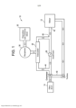
[010] Fazendo agora referência à fig. 1, é descrito um sistema de ar de um motor turbo- alimentado exemplificativo 10 para prover vácuo a um sistema de vácuo de um veículo. O sistema de ar do motor 10 pode incluir um motor de combustão interna 12, um filtro de ar 14, um evacuador 20, um compressor 24, uma turbina 26, um acelerador 28, um reservatório ou recipiente de vácuo 30, e um dispositivo que consume vácuo 32. O motor de combustão 12 pode ser, por exemplo, um motor de ignição por faísca (SI - Spark Ignited), ou um motor de ignição por compressão (CI - Compression Ignited). Em uma forma de realização, o motor de combustão interna 12 pode estar incluído em um sistema de motor elétrico/bateria que faz parte de um veículo híbrido. Na forma de realização ilustrada na fig. 1, o motor de combustão interna 12 é de impulsionamento reforçado. Isto significa que o compressor 24 e a turbina 26 podem fazer parte de um turbo-alimentador para melhorar a potência de saída e a eficiência geral do motor de combustão interna 12. A turbina 26 pode incluir uma roda de turbina (não ilustrada na figura 1) que arrasta e converte a energia de exaustão em trabalho mecânico, através de um eixo comum 40 para girar uma roda de compressor (não ilustrada na fig. 1) do compressor 24. A roda de compressor ingere, comprime e alimenta o ar a pressões de operação elevadas para o coletor de admissão 42 do motor de combustão interna 12.[010] Referring now to fig. 1, an exemplary turbocharged
[011] O recipiente de vácuo 30 pode ser suprido com vácuo proveniente do evacuador 20. O evacuador 20 é suprido com ar do compressor 24. Especificamente, o ar limpo na pressão atmosférica sai do filtro de ar 14 e pode ser comprimido pelo compressor 24, antes de passar pelo evacuador 20. Como explicado abaixo em maiores detalhes, o evacuador 20 pode ser utilizado para fornecer vácuo ao recipiente de vácuo 30. Em particular, a quantidade de vácuo fornecida pelo evacuador 20 pode ser ajustada com base nas condições de operação específicas do sistema de ar do motor 10, que é explicado abaixo em maiores detalhes.[011] The
[012] O acelerador 28 pode estar localizado a jusante do filtro de ar 14 e do compressor 24, e a montante de um coletor de admissão 42 do motor de combustão interna 12. O acelerador 28 pode ser aberto quando um operador pressiona um pedal de acelerador (não ilustrado). Quando o acelerador 28 é aberto, o ar comprimido do compressor 24 fica livre para encher o coletor de admissão 42 do motor de combustão interna 12, aumentando desse modo a pressão no coletor de admissão 42. Os especialistas na técnica entenderão que o acelerador 28 pode ficar posicionado em uma pluralidade de posições parcialmente abertas, com base na quantidade de pressionamento do acelerador (não ilustrado). Como o sistema de ar do motor 10 é turbo-alimentado, a pressão no coletor de admissão 42 pode aumentar para uma pressão que está acima da pressão atmosférica à medida que o acelerador 28 é aberto.[012] The
[013] O evacuador 20 pode incluir uma primeira conexão de ar do motor 44, uma segunda conexão de ar do motor 46, e uma bomba de vácuo acionada pneumaticamente 50, ilustrada na fig. 2. A primeira conexão de ar do motor 44 do evacuador 20 pode estar fluidicamente conectada ao sistema de ar do motor 10 em um local a montante do acelerador 28 e a jusante do compressor 24. A conexão de ar do motor 46 do evacuador 20 pode estar fluidicamente conectada ao sistema de ar do motor 10 em um local a montante do coletor de admissão 42 e a jusante do acelerador 28. A bomba de vácuo acionada pneumaticamente 50 pode ser utilizada para fornecer vácuo ao recipiente de vácuo 30. Especificamente, a quantidade de vácuo fornecida pela bomba de vácuo acionada pneumaticamente 50 pode ser ajustada com base nas condições de operação específicas do sistema de ar do motor 10, explicado abaixo em maiores detalhes. Embora o evacuador 20 seja ilustrado fornecendo de vácuo ao recipiente de vácuo 30, os especialistas na técnica compreenderão que em uma forma de realização alternativa o evacuador 20 pode fornecer vácuo diretamente ao dispositivo que consume vácuo 32.[013] The
[014] O dispositivo que consume vácuo 32 pode ser um dispositivo que requer vácuo, tal como um reforçador de frenagem. Em uma forma de realização, o dispositivo que consume vácuo 32 também pode incluir consumidores de vácuo adicionais, tais como, por exemplo, atuadores de válvulas de descarga de turbo-alimentadores, atuadores de aquecimento e de ventilação, atuadores de linha de transmissão (por exemplo, atuadores de tração nas quatro rodas), sistemas de purga de vapor de combustível, ventilação do cárter do motor, e sistemas de teste de vazamento do sistema de combustível.[014] The
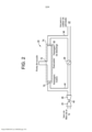
[015] A fig. 2 é um diagrama esquemático de uma forma de realização do evacuador 20 ilustrado na fig. 1, ilustrando a bomba de vácuo acionada pneumaticamente 50. A bomba de vácuo acionada pneumaticamente 50 pode atuar tanto como um aspirador como um ejetor, dependendo da pressão no coletor de admissão 42. Especificamente, um aspirador é um evacuador com sua pressão motriz fixada na pressão atmosférica, e sua descarga abaixo da pressão atmosférica. Um ejetor é um evacuador com sua pressão motriz acima da pressão atmosférica, e sua descarga fixada na pressão atmosférica.[015] Fig. 2 is a schematic diagram of an embodiment of the
[016] Com referência às figs. 1 e 2, conforme aqui utilizado, a bomba de vácuo pneumaticamente acionada 50 pode ser um conjunto de bocal divergente e convergente, com três ou mais conexões. A bomba de vácuo acionada pneumaticamente 50 pode incluir uma porta motriz 70 fluidicamente conectada à primeira conexão de ar do motor 44, uma porta de descarga 74 fluidicamente conectada à conexão de ar do motor 46, e uma ou mais portas de sucção 72 fluidicamente conectadas ao recipiente de vácuo 30 ou a um ou mais dispositivos que requerem vácuo 32. Quando uma pluralidade de portas de sucção 72 estiverem presentes, conforme mostrado em uma primeira forma de realização na fig. 3, em uma segunda forma de realização na fig. 8, e em uma terceira forma de realização na fig. 9, as portas de sucção 72' podem estar conectadas coletivamente ao mesmo dispositivo que requer vácuo 32, ou ao mesmo recipiente de vácuo 30, ou podem estar individualmente conectadas a diferentes dispositivos que requerem vácuo 32a e 32b, incluindo o recipiente de vácuo 30 como um possível dispositivo que requer vácuo.[016] With reference to figs. 1 and 2, as used herein, the pneumatically driven
[017] Especificamente, a porta motriz 70 do aspirador 50 pode estar fluidicamente conectada ao sistema de ar do motor 10 a jusante do compressor 24, e a porta de descarga 74 do aspirador 50 pode estar fluidicamente conectada ao sistema de ar do motor 10 a montante do coletor de admissão 42. Os especialistas na técnica compreenderão prontamente que como o evacuador 20 está conectado ao sistema de ar do motor 10 a jusante do compressor 24, isto geralmente elimina a necessidade de uma válvula de retenção entre o compressor 24 e a porta motriz 70 da bomba de vácuo acionada pneumaticamente 50. Isto ocorre porque a pressão na conexão de ar do motor 44, que está a montante do acelerador 28, deve ser sempre maior do que a pressão na conexão de ar do motor 46, que está a jusante do acelerador 28.[017] Specifically, the
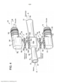
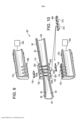
[018] A fig. 3 é uma vista em perspectiva da bomba de vácuo acionada pneumaticamente 50, a fig. 4 é uma vista explodida da bomba de vácuo acionada pneumaticamente 50 ilustrada na fig. 3, e a fig. 5 é uma vista explodida em corte da bomba de vácuo pneumaticamente acionada 50 ilustrada na fig. 4. Com referência às figs. 3, 4 e 5, um corpo 78 da bomba de vácuo pneumaticamente acionada 50 pode definir uma passagem 80 (mostrada na figura 5) que se estende ao longo de um eixo longitudinal A-A. Na forma de realização ilustrada nas figs. 3 a 5, o corpo 78 da bomba de vácuo pneumaticamente acionada 50 inclui quatro portas que podem ser conectadas a subsistemas do motor de combustão interna 12 (figura 1). Especificamente, a bomba de vácuo acionada pneumaticamente 50 pode incluir a porta motriz 70, a porta de descarga 74, e duas portas de sucção 72. Na forma de realização não limitativa ilustrada, a bomba de vácuo acionada pneumaticamente 50 inclui duas portas de sucção 72, com uma das portas de sucção 72 estando localizada ao longo de uma porção superior 84 da bomba de vácuo acionada pneumaticamente 50, e a porta de sucção 72 restante estando localizada ao longo de uma porção inferior 86 da bomba de vácuo acionada pneumaticamente 50. No entanto, deve ser entendido que em outra forma de realização apenas uma porta de sucção 72 localizada ao longo da porção superior 84 ou da porção inferior 86 da bomba de vácuo pneumaticamente acionada 50 também pode ser utilizada. Ou, em outra forma de realização, como mostrado na fig. 8, as duas portas de sucção 72' podem ambas estar dispostas ao longo de uma porção superior 84' da bomba de vácuo acionada pneumaticamente 50', conforme será descrito abaixo em maiores detalhes.[018] Fig. 3 is a perspective view of the pneumatically driven
[019] Com referência à fig. 5, a passagem 80 da bomba de vácuo acionada pneumaticamente 50 pode incluir uma primeira porção afunilada 92 (também referida como cone motriz) em uma seção motriz 90 da passagem 80. A passagem 80 também pode incluir uma segunda porção afunilada 93 (também referida como cone de descarga) em uma seção de descarga 95 da passagem 80. A primeira porção afunilada 92 da passagem 80 pode incluir uma extremidade de entrada 94 e uma extremidade de saída 96. De modo semelhante, a segunda porção afunilada 93 da passagem 80 também pode incluir uma extremidade de entrada 98 e uma extremidade de saída 100.[019] With reference to fig. 5, the
[020] Como visto na fig. 5, a primeira porção afunilada 92 da bomba de vácuo pneumaticamente acionada 50 pode ser fluidicamente acoplada à segunda porção afunilada 93 por meio de uma abertura de Venturi 102A. A abertura de Venturi 102A pode ser uma junção estanque que coloca as portas de sucção 72 em comunicação com a seção motriz 90 e com a seção de descarga 95 da bomba de vácuo acionada pneumaticamente 50. Como melhor observado na fig. 6, a abertura de Venturi 102A pode ser a distância linear L1 medida entre a extremidade de saída 96 da primeira porção afunilada 92 e a extremidade de entrada 98 da segunda porção afunilada 93. Com base na identificação da extremidade de entrada 98 da seção de descarga 95, como mostrado nas figuras, as segunda, terceira e quarta aberturas de Venturi 102B, 102C e 102D são todas consideradas parte da seção de descarga 95, em particular como parte da segunda porção afunilada 93 divergindo para longe da seção motriz 90. A extremidade de saída 96 da primeira porção afunilada 92 da bomba de vácuo pneumaticamente acionada 50 representa a entrada da abertura de Venturi 102A. De modo semelhante, a extremidade de entrada 98 da segunda porção afunilada 93 da bomba de vácuo pneumaticamente acionada 50 representa a saída da abertura de Venturi 102A.[020] As seen in fig. 5, the first tapered
[021] Voltando à fig. 5, as extremidades de entrada 94, 98 e as extremidades de saída 96, 100 da passagem 80 da bomba de vácuo pneumaticamente acionada 50 podem incluir qualquer tipo de perfil, tal como, mas não limitado a, um formato circular, um formato elíptico, ou outro formato poligonal. Além disso, o diâmetro interno gradual e continuamente afunilado, que se estende a partir das extremidades de entrada 94, 98 e das extremidades de saída 96, 100 da passagem 80, pode definir um hiperbolóide ou um cone. Algumas configurações exemplificativas para a extremidade de saída 96 da primeira porção afunilada 92 e para a extremidade de entrada 98 da segunda porção afunilada 93 são apresentadas nas figs. 4 a 6 do pedido de patente co-pendente N° U.S. 14 / 294.727, depositado em 3 de junho de 2014, o qual está aqui incorporado como referência na sua totalidade.[021] Going back to fig. 5, the inlet ends 94, 98 and outlet ends 96, 100 of the
[022] Fazendo referência novamente às figs. 3 a 5, o corpo 78 da bomba de vácuo pneumaticamente acionada 50 pode definir um alojamento 110. O alojamento 110 pode circundar ou definir uma porção da segunda porção afunilada 93 da bomba de vácuo pneumaticamente acionada 50, e em particular pode definir as aberturas de Venturi 102A, 102B, 102C, 102D. Na forma de realização ilustrada, o alojamento 110 pode incluir um perfil geralmente retangular, contudo o alojamento 110, em especial com referência à sua aparência externa, não está limitado a tal perfil retangular.[022] Referring again to figs. 3-5, the
[023] Conforme ilustrado nas figs. 4, 5, 6 e 8, uma pluralidade de aberturas de Venturi adicionais 102B, 102C, 102D estão localizadas a jusante da abertura de Venturi 102A, dentro do alojamento 110. Nas formas de realização ilustradas nas figuras, a bomba de vácuo pneumaticamente acionada 50 inclui um total de quatro aberturas de Venturi. Deve ser entendido que essas ilustrações são meramente formas de realização exemplificativas da bomba de vácuo pneumaticamente acionada 50, e que pode ser possível haver qualquer número de aberturas de Venturi. Para uma forma de realização de uma porta de sucção dupla, tal como mostrado na fig. 8, são necessárias pelo menos duas aberturas de Venturi 102A e 102C, para que pelo menos a abertura de Venturi 102A possa estar em comunicação com a primeira porta de sucção 72'a, e pelo menos a outra abertura de Venturi 102B possa estar em comunicação com a segunda porta de sucção 72'b. Com relação a cada porta de sucção, uma pluralidade de aberturas de Venturi podem estar posicionadas para ficarem alinhadas e em comunicação com cada respectiva porta de sucção, provendo novamente um total de três, quatro ou mais aberturas de Venturi. Conforme ilustrado na fig. 8, as aberturas de Venturi 102A e 102B estão em comunicação com a primeira porta de sucção 72'a, e as aberturas de Venturi 102C e 102D estão em comunicação com a segunda porta de sucção 72'b. Em uma forma de realização com três ou quatro aberturas de sucção (não ilustradas), tendo potencialmente duas aberturas de sucção 72'a, 72'b na superfície superior 130 do alojamento 110, como mostrado na fig. 8, e uma ou duas portas de sucção adicionais na superfície inferior 132 do alojamento 110, um mínimo de três ou quatro aberturas de Venturi estariam presentes.[023] As illustrated in figs. 4, 5, 6 and 8, a plurality of
[024] Cada abertura de Venturi 102A, 102B, 102C, 102D pode ser um espaço vazio localizado dentro do alojamento 110. Especificamente, as aberturas de Venturi 102A, 102B, 102C, 102D podem ser, cada uma, semelhantes a uma seção transversal interna do alojamento 110. Por exemplo, como visto na fig. 5, a abertura de Venturi 102A pode incluir um perfil geralmente retangular que corresponde substancialmente à seção transversal interna do alojamento 110. O fluxo de ar motriz através da primeira porção afunilada 92 da bomba de vácuo acionada pneumaticamente 50 pode aumentar de velocidade, mas cria uma baixa pressão estática. Esta baixa pressão estática extrai ar das portas de sucção 72, 72’a para dentro da abertura de Venturi 102A. As aberturas de Venturi 102B, 102C, 102D restantes, localizadas a jusante da abertura de Venturi 102A, também podem ser utilizadas para adicionalmente extraírem ar de uma ou mais portas de sucção. Nas figs. 3 a 5, as aberturas de Venturi 102B, 102C e 102D extraem ao ar de duas aberturas de sucção 72 ao mesmo tempo. Na fig. 8, a abertura de Venturi 102B é utilizada para adicionalmente extrair ar da primeira porta de sucção 72'a, e as aberturas de Venturi 102C e 102D extraem ar da segunda porta de sucção 72'b. Do mesmo modo, na forma de realização da fig. 9, para o evacuador 50'', as aberturas de Venturi 102A e 102B extraem ar apenas de uma primeira porta de sucção 72'c, já que uma primeira obstrução 202 impede a extração de ar da segunda porta de sucção 72'd, e as aberturas de Venturi 102C e 102D extraem ar apenas da segunda porta de sucção 72'd, uma vez que uma segunda obstrução 204 impede a extração de ar da primeira porta de sucção 72'c.[024] Each Venturi opening 102A, 102B, 102C, 102D can be an empty space located within the
[025] Com referência às figs. 4 e 5, o alojamento 110 pode incluir uma superfície superior 130 e uma superfície inferior 132. Um elemento de válvula de retenção superior 134 e uma peça de sucção superior 136 podem ficar posicionados contra a superfície superior 130, e um elemento de válvula de retenção inferior 140 e uma peça de sucção inferior 142 podem ficar posicionados contra a superfície inferior 132, quando a bomba de vácuo acionada pneumaticamente 50 está montada (conforme ilustrado na figura 3). Embora o elemento de válvula de retenção superior 134 e o elemento de válvula de retenção inferior 140 sejam ilustrados, deve ser entendido que em outra forma de realização o alojamento 110 pode incluir apenas o elemento de válvula de retenção superior 134 ou o elemento de válvula de retenção inferior 140. Especificamente, o elemento de válvula de retenção superior 134 pode ficar posicionado entre a peça de sucção superior 136 e a superfície superior 130 do alojamento 110, e o elemento de válvula de retenção inferior 140 pode ficar posicionado entre a peça de sucção inferior 142 e a superfície inferior 132 do alojamento 110. Em uma forma de realização, a peça de sucção superior 136 e a peça de sucção inferior 142 podem incluir, cada uma, barbatanas 150 para acoplamento com uma mangueira (não ilustrada) que conecta as portas de sucção 72 com o recipiente de vácuo 30 (figura 1). Para as formas de realização mostradas nas figs. 8 e 9, as peças ou partes que são iguais ou semelhantes àquelas identificadas e descritas para as figs. 3 a 5 recebem o mesmo número de referência.[025] With reference to figs. 4 and 5, the
[026] O elemento de válvula de retenção superior 134 e o elemento de válvula de retenção inferior 140 podem ser construídos com um material relativamente flexível, tal como, por exemplo, um elastômero. O material flexível permite que o elemento de válvula de retenção superior 134 e o elemento de válvula de retenção inferior 140 se dobrem ou deformem durante a operação da bomba de vácuo acionada pneumaticamente 50.[026] The upper
[027] Voltando agora à fig. 4, o elemento de válvula de retenção superior 134 pode incluir uma primeira seção 160, e o elemento de válvula de retenção inferior 140 pode incluir uma primeira seção 162. As primeiras seções 160, 162 do elemento de válvula de retenção superior 134 e do elemento de válvula de retenção inferior 140 são, cada uma, substancialmente paralelas ao eixo A-A da bomba de vácuo acionada pneumaticamente 50. Uma pluralidade de linguetas ou abas 166A, 166B, 166C, 166D que se projetam para fora podem estender-se em uma direção geralmente transversal em relação à primeira seção 160 do elemento de válvula de retenção superior 134. Do mesmo modo, uma pluralidade de linguetas ou abas 170A, 170B, 170C, 170D que se projetam para fora estendem-se em uma direção geralmente transversal em relação à primeira seção 162 do elemento de válvula de retenção inferior 140. Cada uma dentre a pluralidade de abas pode estender-se a partir de um lado da primeira seção 160 ou a partir de ambos os lados dessa primeira seção, tipicamente alinhadas em oposição entre si.[027] Returning now to fig. 4, the upper
[028] Cada uma das abas 166A, 166B, 166C, 166D do elemento de válvula de retenção superior 134 pode corresponder a, e está fluidicamente conectada a, uma das aberturas de Venturi 102A, 102B, 102C, 102D. De modo semelhante, cada uma das abas 170A, 170B, 170C, 170D do elemento de válvula de retenção inferior 140 também pode corresponder a, e está fluidicamente conectada a, uma das aberturas de Venturi 102A, 102B, 102C, 102D. Conforme observado na fig. 4, um recesso 174 pode estar localizado ao longo de uma superfície superior 176 da tampa de sucção inferior 142. O recesso 174 pode incluir um perfil que corresponde geralmente ao elemento de válvula de retenção inferior 140. Assim, o elemento de válvula de retenção inferior 140 pode ficar assentado dentro do recesso 174 da peça ou tampa de sucção inferior 142. Deve ser entendido que um recesso semelhante (que não está visível nas figuras) também pode estar localizado ao longo de uma superfície inferior 180 da peça ou tampa de sucção superior 146, incluindo um perfil que corresponde geralmente ao elemento de válvula de retenção superior 134.[028] Each of the
[029] Fazendo referência especificamente à fig. 4, quando a pressão localizada na porta de sucção superior 72 da bomba de vácuo acionada pneumaticamente 50 é igual ou inferior à pressão nas aberturas de Venturi 102A, 102B, 102C, 102D, o elemento de válvula de retenção superior 134 pode ficar assentado nivelado dentro da tampa de sucção superior 136, e as abas 166A, 166B, 166C, 166D não ficam dobradas. De modo semelhante, quando a pressão localizada na porta de sucção inferior 72 da bomba de vácuo acionada pneumaticamente 50 é igual ou inferior à pressão nas aberturas de Venturi 102A, 102B, 102C, 102D, o elemento de válvula de retenção inferior 140 pode ficar assentado nivelado dentro da tampa de sucção inferior 142, e as abas 170A, 170B, 170C, 17D não ficam dobradas. Quando as válvulas de retenção 134, 140 estão na posição fechada, o ar proveniente das portas de sucção superior e inferior 72 da bomba de vácuo acionada pneumaticamente 50 não pode ser aspirado para dentro das aberturas de Venturi 102A, 102B, 102C, 102D.[029] Referring specifically to fig. 4, when the pressure located in the
[030] Quando a pressão localizada na porta de sucção superior 72 da bomba de vácuo pneumaticamente acionada 50 é maior do que a pressão nas aberturas de Venturi 102A, 102B, 102C, 102D, o elemento de válvula de retenção superior 134 pode se abrir. Especificamente, a válvula de retenção superior 134 é flexível o suficiente para que as abas 166A, 166B, 166C, 166D possam se dobrar para dentro ao longo da primeira porção 160 e em direção às aberturas de Venturi 102A, 102B, 102C, 102D, permitindo deste modo que o ar proveniente da porta de sucção superior 72 seja aspirado para dentro das aberturas de Venturi 102A, 102B, 102C, 102D. De modo semelhante, quando a pressão localizada na porta de sucção inferior 72 da bomba de vácuo pneumaticamente acionada 50 é maior do que a pressão nas aberturas de Venturi 102A, 102B, 102C, 102D, o elemento de válvula de retenção inferior 140 pode se abrir. Especificamente, a válvula de retenção inferior 140 é flexível o suficiente para que as abas 170A, 170B, 170C, 170D possam dobrar-se para dentro ao longo da primeira porção 162 e em direção às aberturas de Venturi 102A, 102B, 102C, 102D, permitindo assim que o ar proveniente da porta de sucção inferior 72 seja aspirado para dentro das aberturas de Venturi 102A, 102B, 102C, 102D.[030] When the pressure located in the
[031] Os especialistas na técnica compreenderão facilmente que cada uma das abas 166A, 166B, 166C, 166D do elemento de válvula de retenção superior 134 pode dobrar-se independentemente uma da outra. De modo semelhante, cada uma das abas 170A, 170B, 170C, 170D do elemento de válvula de retenção inferior 140 também pode dobrar-se independentemente uma da outra. Deste modo, durante algumas condições de operação da bomba de vácuo acionada pneumaticamente 50, apenas uma porção das aberturas de Venturi 102A, 102B, 102C, 102D pode ter suas respectivas válvulas de retenção abertas, para permitir que o ar seja aspirado para fora do recipiente de vácuo 30 (fig. 1), enquanto que as aberturas restantes 102A, 102B, 102C, 102D podem ter suas correspondentes válvulas de retenção fechadas. Os especialistas na técnica compreenderão prontamente que as válvulas de retenção 134, 140 ilustradas nas figuras são uma forma de realização da presente descrição, e que outros tipos de válvulas de retenção também podem ser utilizados.[031] Those skilled in the art will readily understand that each of the
[032] A fig. 6 é uma vista em corte ampliada das aberturas de Venturi 102A, 102B, 102C, 102D localizadas no interior do alojamento 110 da bomba de vácuo acionada pneumaticamente 50. Conforme mencionado acima, a abertura de Venturi 102A pode ser definida como a distância linear L1 medida entre a extremidade de saída 96 da primeira porção afunilada 92 (vista na figura 5) e a extremidade de entrada 98 da segunda porção afunilada 93 (observada na figura 5). As aberturas de Venturi 102B, 102C, 102D restantes também incluem respectivas distâncias lineares L2, L3, L4. Estas distâncias lineares são medidas, cada uma, a partir de uma respectiva parede de entrada e uma parede de saída de cada abertura. Especificamente, a abertura de Venturi 102B é medida entre uma superfície de entrada 182 e uma superfície de saída 184, a abertura de Venturi 102C é medida entre uma superfície de entrada 186 e uma superfície de saída 188, e a abertura de Venturi 102D é medida entre uma superfície de entrada 190 e uma superfície de saída 192. As superfícies de entrada 182, 186 e 190 e as superfícies de saída 184, 188 e 192 são todas definidas pelo alojamento 110 da bomba de vácuo acionada pneumaticamente 50.[032] Fig. 6 is an enlarged cross-sectional view of the
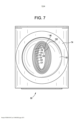
[033] A fig. 7 é uma ilustração da bomba de vácuo pneumaticamente acionada 50 vista a partir da porta de descarga 74. Com referência às figs. 6 e 7, o perfil divergente da segunda porção afunilada 93 da bomba de vácuo acionada pneumaticamente 50 cria um desvio ou diferença nas aberturas de entrada e de saída de cada abertura de Venturi 102A, 102B, 102C e 102D. Como visto nas figs. 5, 7, 8 e 9, as aberturas de entrada e de saída das aberturas de Venturi 102A, 102B, 102C, 102D incluem cada uma um perfil substancialmente elíptico. No entanto, conforme explicado acima, em outra forma de realização as aberturas de entrada e de saída podem incluir outro tipo de perfil. Conforme indicado na fig. 7, mas também aplicável às figs. 5, 8 e 9, a extremidade de saída 96 da primeira porção afunilada 92 (que representa a entrada da abertura de Venturi 102A) inclui uma abertura O1, e a extremidade de entrada 98 da segunda porção afunilada 93 (que representa a saída da abertura de Venturi 102A) inclui uma abertura O2. O perfil da abertura O2 da saída da abertura de Venturi 102A é dimensionado para ser maior do que o da abertura O1 da entrada da mesma abertura de Venturi. Em outras palavras, existe um desvio entre as aberturas de entrada e de saída da abertura de Venturi 102A. Um primeiro desvio 1 representa a diferença entre as aberturas de entrada e de saída da abertura de Venturi 102A. Em uma forma de realização não limitativa, o primeiro desvio 1 pode ser de cerca de 0,25 milímetros.[033] Fig. 7 is an illustration of the pneumatically driven
[034] Continuando com a referência a ambas as figs. 6 e 7, uma abertura O3 está associada com a superfície de entrada 182 da abertura de Venturi 102B, e uma abertura O4 está associada com a superfície de saída 184 da segunda abertura de Venturi 102B. De maneira semelhante à abertura de Venturi 102A, a abertura O4 da superfície de saída 184 é maior do que a abertura O3 da superfície de entrada 182. Um segundo desvio 2 representa a diferença entre a superfície de entrada 182 e a superfície de saída 184 da segunda abertura de Venturi 102B. De modo similar, uma abertura O5 está associada com a superfície de entrada 186 da abertura de Venturi 102C, e uma abertura O6 está associada à saída 188 da abertura de Venturi 102C. Um terceiro desvio 3 representa a diferença entre a superfície de entrada 186 e a superfície de saída 188 da abertura de Venturi 102C. Finalmente, uma abertura O7 está associada com a superfície de entrada 190 da abertura de Venturi 102D, e uma abertura O8 está associada à saída 192 da abertura de Venturi 102D. Um quarto desvio 4 representa a diferença entre a superfície de entrada 190 e a superfície de saída 192 da abertura de Venturi 102D.[034] Continuing with the reference to both figs. 6 and 7, an opening O3 is associated with the
[035] Fazendo referência em geral às figs. 5 e 6, durante a operação pode ser criada uma área de pressão mínima dentro do corpo 78 da bomba de vácuo pneumaticamente acionada 50. Em particular, a área de pressão mínima pode estar localizada adjacente ou dentro de uma ou mais das aberturas de Venturi 102A, 102B, 102C, 102D da bomba de vácuo acionada pneumaticamente 50. A área de pressão mínima também representa uma área de velocidade máxima dentro da bomba de vácuo acionada pneumaticamente 50. Os especialistas na técnica compreenderão prontamente que se a bomba de vácuo acionada pneumaticamente 50 estiver operando como um ejetor, então, à medida que a pressão motriz da bomba de vácuo acionada pneumaticamente 50 aumenta, a localização da pressão mínima dentro da bomba de vácuo acionada pneumaticamente 50 pode se deslocar ou se mover para jusante dentro da segunda porção afunilada 73. Como a localização da pressão mínima no interior da bomba de vácuo acionada pneumaticamente 50 se move para jusante da abertura de Venturi 102A, as aberturas de Venturi 102B, 102C, 102D podem ser utilizadas para aspirar ar para fora do recipiente de vácuo 30. Os especialistas na técnica entenderão também que se a bomba de vácuo acionada pneumaticamente 50 estiver operando como um aspirador, então, à medida que a pressão na porta de descarga 74 diminui, a localização da pressão mínima também pode se deslocar ou se mover para jusante.[035] Making general reference to figs. 5 and 6, during operation an area of minimum pressure may be created within the
[036] Continuando com a referência à fig. 6, as distâncias lineares L1, L2, L3, L4 de cada uma das aberturas de Venturi 102A, 102B, 102C, 102D localizadas no interior do alojamento 110 da bomba de vácuo pneumaticamente acionada 50 podem ser “sintonizadas” ou ajustadas de maneira personalizada, de modo a acomodarem a localização da pressão mínima dentro da bomba de vácuo pneumaticamente acionada 50. Especificamente, uma das distâncias lineares L1, L2, L3, L4 de uma das aberturas de Venturi 102A, 102B, 102C, 102D localizadas dentro do alojamento 110 da bomba de vácuo pneumaticamente acionada 50 pode ser concebida para ser de comprimento menor ou mais estreito, se for desejado um vácuo de sucção mais alto (isto é, pressões de sucção mais baixas) em um conjunto específico de condições de operação.[036] Continuing with the reference to fig. 6, the linear distances L1, L2, L3, L4 of each of the
[037] Além da diminuição do comprimento de uma das aberturas de Venturi 102A, 102B, 102C, 102D, as distâncias de desvio (isto é, o primeiro desvio 1, o segundo desvio 2, o terceiro desvio 3 ou o quarto desvio 4) também podem ser diminuídas, a fim de ser produzido um vácuo de sucção mais alto (isto é, pressões de sucção mais baixas) em um conjunto específico de condições de operação. Em outras palavras, se uma abertura de Venturi específica dentre as aberturas de Venturi diminuir de comprimento, então a diferença entre a respectiva abertura de entrada e saída daquela abertura de Venturi específica também deve diminuir. De um modo semelhante, uma das distâncias lineares L1, L2, L3, L4 de uma das aberturas de Venturi 102A, 102B, 102C, 102D localizadas dentro do alojamento 110 da bomba de vácuo pneumaticamente acionada 50 pode ser concebida para ser de comprimento maior ou mais largo, se for desejada uma taxa de fluxo de sucção mais elevada em um conjunto específico de condições de operação. Além do aumento do comprimento de uma das aberturas de Venturi 102A, 102B, 102C, 102D, a distância de desvio associada com uma das aberturas de Venturi (isto é, o primeiro desvio 1, o segundo desvio 2, o terceiro desvio 3 ou o quarto desvio 4) também deve ser aumentada para produzir uma taxa de fluxo de sucção mais alta em um conjunto específico de condições operacionais. Em outras palavras, se uma abertura de Venturi específica dentre as aberturas de Venturi aumentar de comprimento, então a diferença entre as respectivas aberturas de entrada e saída daquela abertura de Venturi específica também deve aumentar.[037] In addition to decreasing the length of one of the
[038] Um conjunto específico de condições de operação pode ser definido pelas pressões tanto na porta motriz 70 como na porta de descarga 74 da bomba de vácuo pneumaticamente acionada 50. Por exemplo, durante um conjunto de condições de operação a porta motriz 70 está na pressão atmosférica, e a porta de descarga 74 está a cerca de oitenta por cento da pressão atmosférica. Durante este conjunto de condições de operação, a bomba de vácuo acionada pneumaticamente 50 opera como um aspirador. Neste exemplo, a localização da pressão mínima dentro da bomba de vácuo pneumaticamente acionada 50 pode ser assumida ou determinada como estando na abertura de Venturi 102A. Se o motor 12 (ilustrado na fig. 1) operar para produzir essas condições exemplificativas durante um período de tempo significativo, então um projetista ou engenheiro pode determinar que é geralmente vantajoso ajustar a distância linear L1 da abertura de Venturi 102A em conformidade (isto é, a distância linear L1 da abertura de Venturi 102A deve ser alargada ou estreitada, dependendo dos requisitos). Além do ajuste da distância linear L1, deve ser entendido que o segundo desvio 2 também pode ser ajustado adequadamente. Por exemplo, se a distância linear L1 da abertura de Venturi 102A for aumentada, então o segundo desvio 2 também pode aumentar. Similarmente, se a distância linear L1 da abertura de Venturi 102A for diminuída, então o segundo desvio 2 também pode diminuir.[038] A specific set of operating conditions can be defined by the pressures in both the
[039] Em outro exemplo ilustrativo, se a pressão da porta motriz 70 for superior à da pressão atmosférica (por exemplo, de aproximadamente 168 quilopascais, ou 17.131,0 kgf/m2), e se a pressão da porta de descarga 74 também for superior à da pressão atmosférica mas inferior à da porta motriz 70 (por exemplo, de cerca de 135 quilopascais, ou 13.765,9 kgf/m2), então a bomba de vácuo acionada pneumaticamente 50 está operando como um ejetor. Neste exemplo, a localização da pressão mínima dentro da bomba de vácuo pneumaticamente acionada 50 é assumida ou determinada como estando na abertura de Venturi 102C. Se o motor 12 (ilustrado na figura 1) operar para produzir estas condições exemplificativas durante um período de tempo significativo, então um projetista ou engenheiro pode determinar que é geralmente vantajoso ajustar a distância linear L3 da abertura de Venturi 102C em conformidade (isto é, a abertura de Venturi 102C deve ser alargada ou estreitada). Além do ajuste da distância linear L3 da abertura de Venturi 102C, deve ser entendido que o terceiro desvio 3 também pode ser ajustado em conformidade. Por exemplo, se a distância linear L3 da abertura de Venturi 102C for aumentada, então o terceiro desvio 3 também pode aumentar. Similarmente, se a distância linear L3 da abertura de Venturi 102C for diminuída, então o terceiro desvio 3 também pode diminuir.[039] In another illustrative example, if the pressure of the
[040] Com referência agora às figs. 8 e 9, são providas duas formas de realização alternativas nas quais as primeira e segunda aberturas de Venturi 102A e 102B estão em comunicação com uma primeira porta de sucção 72'a, 72'c, respectivamente, e as segunda e terceira aberturas de Venturi 102C e 102D são em comunicação com a segunda porta de sucção 72'b, 72'd, respectivamente. A comunicação é controlada pela presença de um elemento de válvula de retenção 134 e/ou 140, caso esteja presente. As primeiras portas de sucção 72'a, 72'c estão conectadas a um primeiro dispositivo que requer vácuo 32a, e as segundas portas de sucção 72'b, 72'd estão conectadas a um segundo dispositivo que requer vácuo 32b.[040] With reference now to figs. 8 and 9, two alternative embodiments are provided in which first and
[041] Nesta primeira forma de realização de porta de sucção dedicada, o primeiro dispositivo que requer vácuo 32a é um recipiente de reforço de freio e o segundo dispositivo que requer vácuo 32b é um recipiente de purga de vapor de combustível. Para esta primeira forma de realização, tal como mostrado nas figs. 8 e 9, as primeira e segunda aberturas de Venturi 102A e 102B estão posicionadas mais próximas da saída motriz. Esta posição das aberturas de Venturi é vantajosa para um vácuo de sucção mais elevado, o que é desejável para um sistema de reforço de freio, em comparação com as aberturas de Venturi mais próximas da extremidade de saída 100 da seção de descarga 95. Além disso, como explicado acima, as primeira e segunda aberturas de Venturi 102A e 102B podem ser “sintonizadas” para uma sucção de vácuo mais elevada, diminuindo-se a distância linear L1 e/ou diminuindo-se o primeiro desvio 1 e/ou o segundo desvio 2. Nesta terceira forma de realização, as terceira e quarta aberturas de Venturi 102C e 102D estão posicionadas mais próximas da extremidade de saída 100 da seção de descarga 95. Esta posição das aberturas de Venturi é vantajosa para uma taxa de fluxo de sucção mais elevada, tipicamente durante um tempo mais longo, o que é desejável para um recipiente de purga de vapor de combustível, em comparação com as primeira e segunda aberturas de Venturi 102A e 102B. Além disso, como explicado acima, as terceira e quarta aberturas de Venturi 102C e 102D podem ser “sintonizadas” para taxas de fluxo de sucção mais elevadas, aumentando-se a distância linear L3 e/ou L4 e/ou aumentando-se o terceiro desvio 3 e/ou o quarto desvio 4.[041] In this first embodiment of a dedicated suction port, the first vacuum-requiring
[042] Em outra forma de realização de porta de sucção dedicada, o primeiro dispositivo que requer vácuo 32a é um acionador pneumático de bypass (desvio) de um turbo- alimentador, e o segundo dispositivo que requer vácuo 32b é um recipiente de purga de vapor de combustível. Aqui, como mostrado nas figs. 8 e 9, as primeira e segunda aberturas de Venturi 102A e 102B estão conectadas ao primeiro dispositivo que requer vácuo, e estão posicionadas mais próximas da saída motriz. Esta posição das aberturas de Venturi é vantajosa para um vácuo de sucção mais elevado, o que é desejável para um atuador pneumático de bypass de um turbo-alimentador. Além disso, como explicado acima, as primeira e segunda aberturas de Venturi 102A e 102B podem ser “sintonizadas” para um vácuo de sucção mais elevado, diminuindo-se a distância linear L1 e/ou diminuindo-se o primeiro desvio 1 e/ou o segundo desvio 2. Além disso, se vácuo adicional for necessário para operar o atuador pneumático de bypass do turbo-alimentador, a terceira abertura de Venturi 102C também pode estar em comunicação apenas com a primeira porta de sucção 72'a, 72'c. Consequentemente, as terceira e quarta aberturas de Venturi 102C e 102D, ou a quarta abertura de Venturi 102D sozinha, ou a quarta abertura de Venturi 102D e uma ou mais aberturas de Venturi adicionais (não ilustradas), podem estar em comunicação com o segundo dispositivo que requer vácuo 32b. Esta posição das aberturas de Venturi, mais próximas da extremidade de saída 100 da seção de descarga 95, é vantajosa para uma taxa de fluxo de sucção mais elevada, tipicamente durante um período de tempo mais longo, o que é desejável para um recipiente de purga de vapor de combustível. Além disso, como explicado acima, estas aberturas de Venturi podem ser ajustadas para taxas de fluxo de sucção mais elevadas, aumentando-se suas respectivas distâncias lineares e/ou aumentando-se seus respectivos desvios 3.[042] In another embodiment of a dedicated suction port, the first device that requires
[043] Deve ser entendido que são possíveis várias combinações de dispositivos para os primeiro e segundo dispositivos que requerem vácuo 32a, 32b, e além disso um terceiro e/ou quarto dispositivo que requer vácuo podem ser conectados ao mesmo evacuador, inclusive através de portas de sucção adicionais, tal como explicado acima. Dependendo do número de dispositivos que requerem vácuo, e do tipo desses dispositivos, as aberturas de Venturi 102A, 102B, 102C, 102D conectadas aos respectivos dispositivos devem ser escolhidas dependendo da necessidade do dispositivo por alto ou baixo vácuo de sucção, ou alta ou baixa taxa de fluxo de sucção, e elas podem ser “sintonizadas” ou ajustadas de maneira personalizada de acordo com essas necessidades. Por exemplo, em uma forma de realização, uma das aberturas de Venturi 102A, 102B, 102C, 102D pode ser aumentada em comprimento para prover uma taxa de fluxo de sucção mais elevada, em um primeiro conjunto de condições de operação, e as aberturas de Venturi 102A, 102B, 102C, 102D restantes podem ter seus comprimentos reduzidos para proverem um vácuo de sucção mais elevado, em outro conjunto de condições de operação.[043] It should be understood that various combinations of devices are possible for the first and second devices that require
[044] Fazendo referência novamente à fig. 9, a comunicação entre as aberturas de Venturi 102A a 102D é controlada pela presença de elementos de válvula de retenção 134, 140. Aqui, uma vez que apenas as primeira e segunda aberturas de Venturi 102A e 102B se fluidicamente comunicam com a primeira porta de sucção 72'c, existe uma obstrução 204 que obstrui (impede) a comunicação entre quaisquer aberturas de Venturi a jusante e a primeira porta de sucção 72'c. De modo semelhante, uma vez que apenas as terceira e quarta aberturas de Venturi 102C e 102D se fluidicamente comunicam com a segunda porta de sucção 72’d, existe uma obstrução 202 que obstrui ou impede a comunicação entre quaisquer aberturas de Venturi a montante e a segunda porta de aspiração 72’d.[044] Referring again to fig. 9, communication between the
[045] Em uma forma de realização alternativa, conforme ilustrado na fig. 10, em vez de existirem as obstruções 202 ou 204 coordenadas com aberturas de Venturi selecionadas, é provido um elemento de válvula de retenção 208 que inclui abas selecionadas que são rígidas, incluídas na seção direita 212, e outras abas selecionadas que são elasticamente flexíveis, incluídas na seção esquerda 210, de modo a se deslocarem entre uma posição fechada e uma posição aberta. Embora o elemento de válvula de retenção 208 esteja ilustrado metade com abas rígidas e metade com abas flexíveis, as abas rígidas e flexíveis podem estar dispersas conforme requerido de modo a se coordenarem com as aberturas de Venturi selecionadas e suas respectivas portas de sucção.[045] In an alternative embodiment, as illustrated in fig. 10, instead of existing
[046] Como observado na fig. 8, um inserto do tipo flecha 220 pode ser incluído em qualquer uma das formas de realização aqui explicadas. O inserto do tipo flecha 220 está descrito no pedido de patente provisório co-pendente e em co-propriedade n° U.S. 62/042.569, depositado em 27 de agosto de 2014, que é aqui incorporado como referência na sua totalidade.[046] As seen in fig. 8, an arrow-
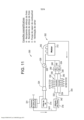
[047] Fazendo agora referência à fig. 11, é descrito um sistema de ar para um motor turbo-alimentado exemplificativo 300, para prover vácuo. O sistema de ar para o motor 300 pode incluir um motor de combustão interna 312, um filtro de ar 314, uma válvula de fluxo 316, um evacuador de múltiplas portas 330, um compressor 324, uma turbina (não ilustrada), um acelerador 328, e um recipiente de vapor de combustível 331. Conforme explicado abaixo em mais detalhes, o evacuador de múltiplas portas 330 pode prover vácuo para uma pluralidade de dispositivos que consomem vácuo, tais como um recipiente de reforço de freio (não ilustrado na figura 11), o recipiente de vapor de combustível 331, e um sistema de ventilação de cárter 352.[047] Referring now to fig. 11, an air system for an exemplary
[048] De modo semelhante à forma de realização ilustrada na fig. 1, o motor de combustão interna 312 pode ser, por exemplo, um motor de ignição por faísca (SI), um motor de ignição por compressão (CI), ou parte de um sistema de motor elétrico / bateria em um veículo híbrido. O compressor 324 e a turbina podem fazer parte de um turbo-alimentador para melhorar a potência de saída e a eficiência geral do motor de combustão interna 312. A turbina pode incluir uma roda de turbina (não ilustrada na figura 11) que arrasta e converte a energia de exaustão em trabalho mecânico, através de um eixo comum para girar uma roda de compressor (não ilustrada na fig. 11) do compressor 324. A roda de compressor ingere, comprime e alimenta o ar a pressões de operação elevadas para o coletor de admissão 342 do motor de combustão interna 312. O acelerador 328 está localizado a jusante do filtro de ar 314 e do compressor 324, e a montante do coletor de admissão 342 do motor de combustão interna 312.[048] Similar to the embodiment illustrated in fig. 1, the
[049] O evacuador 330 inclui uma primeira entrada motriz 332, uma segunda entrada motriz 334, uma primeira saída de descarga 336, uma segunda saída de descarga 338, e uma bomba de vácuo acionada pneumaticamente 340. Na forma de realização ilustrada na fig. 11, a primeira entrada motriz 332 do evacuador 330 está fluidicamente conectada com o recipiente de vapor de combustível 331, conforme representado pela linha de conduto 343. A válvula de fluxo 316 está localizada dentro da linha de conduto 343. A válvula de fluxo 316 pode ser uma válvula de fechamento, sendo usada para controlar o vácuo provido ao recipiente de vapor de combustível 331. Os especialistas na técnica compreenderão prontamente que o recipiente de vapor de combustível 331 pode necessitar de purga somente durante um período de tempo especificado após a partida do motor de um veículo. Um exemplo não limitativo da válvula de fluxo está descrito no pedido de patente provisório co-pendente e em co-propriedade n° U.S. 61 / 914.658, depositado em 11 de dezembro de 2013, que é aqui incorporado como referência na sua totalidade.[049] The
[050] Continuando com a referência à fig. 11, a segunda entrada motriz 334 do evacuador 330 está fluidicamente conectada com o sistema de ventilação de cárter 352, conforme representado pela linha de conduto 344. Ambas as saídas de descarga 336, 338 do evacuador 330 estão fluidicamente conectadas ao sistema de ar do motor 300 em um local a montante do coletor de admissão 342 e a jusante de uma saída 329 do acelerador 328. Especificamente, uma primeira válvula de retenção 350 pode ser incluída em uma linha de conduto 348 entre a primeira saída de descarga 336 do evacuador 330 e junção entre o acelerador 328 e o coletor de admissão 342. Da mesma forma, uma segunda válvula de retenção 354 pode ser incluída em uma linha de conduto 349 entre a segunda saída de descarga 338 do evacuador 330 e a junção entre o acelerador 328 e o coletor de admissão 342.[050] Continuing with the reference to fig. 11, the
[051] A bomba de vácuo acionada pneumaticamente 340 pode fornecer vácuo para uma pluralidade de dispositivos que consomem vácuo. Em particular, a bomba de vácuo acionada pneumaticamente 340 fornece vácuo ao recipiente de reforço de freio (não ilustrado), ao recipiente de vapor de combustível 331, e ao sistema de ventilação de cárter 352. Conforme explicado abaixo em mais detalhes, a bomba de vácuo acionada pneumaticamente 340 está fluidicamente conectada ao recipiente de reforço de freio, ao recipiente de vapor de combustível 331 e ao sistema de ventilação de cárter 352 através de uma pluralidade de portas de sucção superiores A1, B1, C1, D1. A bomba de vácuo acionada pneumaticamente 340 também está fluidicamente conectada ao recipiente de reforço de freio, ao recipiente de vapor de combustível 331 e ao sistema de ventilação de cárter 352 através de uma pluralidade de portas de sucção inferiores A2, B2, C2, D2. Os especialistas na técnica entenderão prontamente que, enquanto o recipiente de reforço de freio, o recipiente de vapor de combustível 331 e o sistema de ventilação de cárter 352 são ilustrados ou descritos na fig. 11, a bomba de vácuo acionada pneumaticamente 340 pode incluir portas de sucção adicionais para também prover vácuo a outros dispositivos que consomem vácuo dentro de um veículo. Alternativamente, a bomba de vácuo acionada pneumaticamente 340 pode prover vácuo para diferentes dispositivos que consomem vácuo dentro de um veículo.[051] The pneumatically driven
[052] O evacuador 330 pode operar para produzir vácuo para os vários sistemas que requerem vácuo, se a pressão nas entradas motrizes 332, 334 do evacuador 330 for igual à pressão atmosférica e a pressão nas saídas de descarga 336, 338 for inferior à pressão nas entradas motrizes 332, 334. Em outras palavras, o evacuador 330 funciona como um aspirador durante a operação do motor 312.[052] The
[053] Como ilustrado na fig. 11, o evacuador 330 inclui múltiplas portas de sucção conectadas aos múltiplos dispositivos que requerem vácuo. Especificamente, a primeira porta de sucção superior A1, localizada mais próxima da primeira entrada motriz 332 do evacuador 330, está fluidicamente conectada ao sistema de reforço de freio. A segunda porta de sucção superior B1, que está localizada imediatamente adjacente à primeira porta de sucção A1 do evacuador 330, também está fluidicamente conectada ao sistema de reforço de freio. Conforme explicado acima, a proximidade das primeira e segunda portas de sucção superiores A1, B1 com a primeira entrada motriz 332 do evacuador 330 facilita uma sucção de vácuo mais elevada, que é requerida pelos sistemas de reforço de freio. De modo semelhante, a primeira porta de sucção inferior A2, localizada mais próxima da segunda entrada motriz 334 do evacuador 330, também está fluidicamente conectada ao sistema de reforço de freio. A segunda porta de sucção inferior B2, que está localizada imediatamente adjacente à porta de sucção A2 do evacuador 330, está fluidicamente conectada ao sistema de reforço de freio. A proximidade das primeira e segunda portas de sucção inferiores A2, B2 com a segunda entrada motriz 334 do evacuador 330 também facilita uma sucção de vácuo mais elevada.[053] As illustrated in fig. 11, the
[054] Continuando com a referência à fig. 11, a terceira porta de sucção superior C1, que é imediatamente adjacente à segunda porta de sucção superior B1 do evacuador 330, está fluidicamente conectada ao recipiente de vapor de combustível 331. A quarta porta de sucção superior D1, que é imediatamente adjacente à primeira saída de descarga 336 do evacuador 330, está fluidicamente conectada ao sistema de ventilação de cárter 352. Conforme explicado acima, a proximidade das terceira e quarta portas de sucção superiores C1, D1 com a saída de descarga 336 do evacuador 330 facilita uma taxa de fluxo de sucção mais elevada. De maneira semelhante, a terceira porta de sucção inferior C2, que é imediatamente adjacente à segunda porta de sucção inferior B2 do evacuador 330, também está fluidicamente conectada ao recipiente de vapor de combustível 331. A quarta porta de sucção inferior D2, que é imediatamente adjacente à segunda saída de descarga 338 do evacuador 330, está fluidicamente conectada ao sistema de ventilação de cárter 352. A proximidade das terceira e quarta portas de sucção inferiores C2, D2 com a segunda saída de descarga 338 do evacuador 330 também facilita uma taxa de fluxo de sucção mais elevada.[054] Continuing with the reference to fig. 11, the third upper suction port C1, which is immediately adjacent the second upper suction port B1 of the
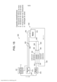
[055] A fig. 12 é uma vista em elevação da bomba de vácuo acionada pneumaticamente 340, e a fig. 13 é uma vista em corte da bomba de vácuo acionada pneumaticamente 340 tomada ao longo da linha de corte C-C na fig. 12. Com referência às figs. 12 e 13, a bomba de vácuo acionada pneumaticamente 340 pode definir duas passagens 480, 482. Especificamente, uma primeira passagem ou passagem superior 480 pode definir a primeira entrada motriz 332 e a primeira saída de descarga 336. A passagem superior 480 pode incluir uma primeira porção afunilada 492 (também referida como cone motriz) em uma seção motriz 490 da passagem superior 480. A passagem superior 480 também pode incluir uma segunda porção afunilada 493 (também referida como cone de descarga) em uma seção de descarga 495 da passagem superior 480. A primeira porção afunilada 492 da passagem 480 pode incluir uma extremidade motriz de entrada 494 e uma extremidade motriz de saída 496. De modo semelhante, a segunda porção afunilada 493 da passagem superior 480 também pode incluir uma extremidade de entrada de descarga 498 e uma extremidade de saída de descarga 500.[055] Fig. 12 is an elevational view of the pneumatically operated
[056] Uma segunda passagem ou passagem inferior 482 pode definir a segunda entrada motriz 334 e a segunda saída de descarga 338. A passagem inferior 482 pode incluir uma primeira porção afunilada 492' em uma seção motriz 490' da passagem inferior 482. A passagem inferior 482 também pode incluir uma segunda porção afunilada 493' em uma seção de descarga 495' da passagem inferior 482. A primeira porção afunilada 492' da passagem inferior 482 pode incluir uma extremidade motriz de entrada 494' e uma extremidade motriz de saída 496'. De maneira semelhante, a segunda porção afunilada 493' da passagem inferior 482 também pode incluir uma extremidade de entrada de descarga 498' e uma extremidade de saída de descarga 500'. Deve ser entendido que enquanto as figuras ilustram o evacuador 330 incluindo duas entradas motrizes e duas saídas motrizes, o evacuador 330 também pode incluir mais do que duas entradas motrizes. Além disso, o evacuador 330 também pode incluir mais do que duas saídas de descarga. No entanto, deve ser entendido que o número de entradas motrizes do evacuador 330 deve ser igual ao número de saídas de descarga.[056] A second passageway or
[057] Como observado na fig. 13, as primeiras porções afuniladas 492, 492' da bomba de vácuo acionada pneumaticamente 340 podem ser fluidicamente acopladas às segundas porções afuniladas 493, 493' por meio de uma abertura de Venturi 502A. Em particular, a abertura de Venturi 502A pode estar localizada entre as extremidades motrizes de saída 496, 496' das primeiras porções afuniladas 492, 492' e as extremidades de entrada 498, 498' das segundas porções afuniladas 493, 493'. Um corpo 508 da bomba de vácuo acionada pneumaticamente 340 pode definir um alojamento 510. O alojamento 510 pode circundar ou definir uma porção das segundas porções afuniladas 493 493' da bomba de vácuo acionada pneumaticamente 340. Em particular, o alojamento 508 pode definir a abertura de Venturi 502A, bem como uma pluralidade de aberturas de Venturi 502B, 502C, 502D adicionais. Na forma de realização ilustrada, o alojamento 510 pode incluir um perfil geralmente retangular, contudo deve ser entendido que esta forma de realização é de natureza meramente exemplificativa, e o alojamento 510 não está limitado a um perfil retangular.[057] As seen in fig. 13, the first
[058] As aberturas de Venturi 502B, 502C, 502D estão localizadas a jusante da abertura de Venturi 502A, dentro do alojamento 508. Nas formas de realização ilustradas nas figuras, a bomba de vácuo acionada pneumaticamente 340 inclui um total de quatro aberturas de Venturi. Deve ser entendido que estas ilustrações são apenas formas de realização exemplificativas da bomba de vácuo acionada pneumaticamente 340, e que é possível qualquer número de aberturas de Venturi. Em particular, em outra forma de realização, o evacuador 330 pode incluir apenas uma única abertura de Venturi utilizada para acoplar fluidicamente as primeiras porções afuniladas 492, 492' da bomba de vácuo acionada pneumaticamente 340 com as segundas porções afuniladas 493, 493'. No entanto, os especialistas na técnica compreenderão prontamente que, na forma de realização ilustrada na fig. 11, são necessárias pelo menos quatro aberturas de Venturi, para que pelo menos as aberturas de Venturi 502A, 502B possam estar em comunicação com o recipiente de reforço de freio, a abertura de Venturi 502C possa estar em comunicação com o recipiente de vapor de combustível 331 (figura 11), e a abertura de Venturi 502D possa estar em comunicação com o sistema de ventilação de cárter 352 (figura 11).[058] The
[059] Conforme observado na fig. 13, um inserto do tipo flecha 516 pode estar disposto dentro da primeira porção afunilada 492 do evacuador 330, e pode estender-se dentro de uma ou mais das aberturas de Venturi 502A, 502B, 502C, 502D. De modo semelhante, um inserto do tipo flecha 516' pode estar disposto dentro da primeira porção afunilada 492' do evacuador 330, e também pode estender-se dentro de uma ou mais das aberturas de Venturi 502A, 502B, 502C, 502D.[059] As seen in fig. 13, an arrow-
[060] Cada abertura de Venturi 502A, 502B, 502C, 502D pode ser um espaço vazio localizado dentro do alojamento 508. Especificamente, as aberturas de Venturi 502A, 502B, 502C, 502D podem ser, cada uma, semelhantes a uma seção transversal interna do alojamento 508. Por exemplo, a abertura de Venturi 502A pode incluir um perfil geralmente retangular que corresponde substancialmente à seção transversal interna do alojamento 508. Em particular, a primeira porta de sucção superior A1 pode corresponder com a abertura de Venturi 502A do evacuador 330, a segunda porta de sucção superior B1 pode corresponder com a abertura de Venturi 502B do evacuador 330, a terceira porta de sucção superior C1 pode corresponder com a abertura de Venturi 502C do evacuador 330, e finalmente a quarta porta de sucção superior D1 pode corresponder com a abertura de Venturi 502D do evacuador 330.[060] Each Venturi opening 502A, 502B, 502C, 502D can be an empty space located within the
[061] De forma semelhante, a primeira porta de sucção inferior A2 pode corresponder com a abertura de Venturi 502A do evacuador 330, a segunda porta de sucção inferior B2 pode corresponder com a abertura de Venturi 502B do evacuador 330, a terceira porta de sucção inferior C2 pode corresponder com a abertura de Venturi 502C do evacuador 330, e finalmente a quarta porta de sucção inferior D2 pode corresponder com a abertura de Venturi 502D do evacuador 330. Embora as aberturas de sucção inferiores A2, B2, C2, D2 não estejam visíveis nas figs. 12 e 13, deve ser entendido que o alojamento 510 inclui uma superfície superior 512 (visível na figura 12) e uma superfície inferior 514. A superfície inferior 514 (que não está totalmente visível nas figuras) tem um formato e uma geometria substancialmente idênticos aos da superfície superior 512 do alojamento 510.[061] Similarly, the first lower suction port A2 can correspond with the Venturi opening 502A of the
[062] Com referência às figs. 11 a 13, as aberturas de Venturi 502A e 502B extraem ar das primeira e segunda portas de sucção superiores A1, B1, bem como das primeira e segunda portas de sucção inferiores A2, B2, todas ao mesmo tempo. A abertura de Venturi 502C é utilizada para extrair ar da terceira porta de sucção superior C1, bem como da terceira porta de sucção inferior C2. Finalmente, a abertura de Venturi 502D é utilizada para extrair ar da quarta porta de sucção superior D1, bem como da quarta porta de sucção inferior D2. De maneira semelhante às formas de realização acima discutidas e ilustradas nas figs. 2 a 10, as aberturas de Venturi 502A, 502B, 502C, 502D podem ser “sintonizadas” ou ajustadas com base no número de dispositivos que requerem vácuo, bem como com base no tipo específico de dispositivos que requerem vácuo. Por exemplo, em uma forma de realização, as aberturas de Venturi 502A, 502B podem ter seu comprimento aumentado para proverem um vácuo de sucção mais elevado em um primeiro conjunto de condições operacionais, e as aberturas de Venturi 502C, 502D restantes podem ter seu comprimento diminuído para proverem uma maior taxa de fluxo de sucção em outro conjunto de condições de operação.[062] With reference to figs. 11-13,
[063] Continuando com a referência às figs. 11 a 13, a comunicação entre as aberturas de Venturi 502A a 502D e os vários dispositivos que requerem vácuo pode ser controlada pela presença de elementos de válvula de retenção (não ilustrados nas figuras 12 e 13). Especificamente, um elemento de válvula de retenção, semelhante ao elemento de válvula de retenção 134 mostrado na fig. 4, pode ficar disposto ao longo da superfície superior 512 do alojamento 510 do evacuador 330. Contudo, deve ser entendido que o elemento de válvula de retenção disposto ao longo da superfície superior 512 do alojamento 510 deve ser conformado para corresponder com a geometria específica das aberturas de Venturi 502A a 502D. De modo semelhante, um elemento de válvula de retenção, semelhante ao elemento de válvula de retenção 140 mostrado na fig. 4, pode ficar disposto ao longo da superfície inferior 514 do alojamento 510 do evacuador 330. O elemento de válvula de retenção disposto ao longo da superfície inferior 514 do alojamento 510 deve ser conformado para corresponder com a geometria específica das aberturas de Venturi 502A a 502D.[063] Continuing with the reference to figs. 11-13, the communication between the
[064] Na forma de realização ilustrada nas figs. 12 e 13, as aberturas de Venturi 502A, 502B, 502C, 502D estão, cada uma, em comunicação com a primeira entrada motriz 332, com a segunda entrada motriz 334, com a primeira saída de descarga 336, e com a segunda saída de descarga 338. Em outras palavras, o evacuador 330 opera como um único dispositivo de evacuação unitário. Voltando agora à fig. 14, é descrita uma forma de realização alternativa de um evacuador 330' para prover vácuo. O evacuador 330' inclui todos os componentes do evacuador 330 ilustrado nas figs. 12 e 13, e os números de referência das partes semelhantes referem-se aos mesmos componentes; portanto, sua descrição não será duplicada aqui. No entanto, ao contrário da forma de realização ilustrada nas figs. 11 e 12, o evacuador 330' inclui uma parede divisória 320', localizada dentro do alojamento 510 e estendendo-se em uma direção que é substancialmente paralela às entradas motrizes 32, 334 e às saídas de descarga 336, 338. Em outras palavras, a parede divisória 320' estende-se em uma direção substancialmente paralela ao fluxo de fluido dentro do evacuador 330.[064] In the embodiment illustrated in figs. 12 and 13, the
[065] A parede divisória 320' pode ser utilizada para seccionar ou isolar porções das aberturas Venturi, de modo a que o fluido só possa fluir a partir de uma das entradas motrizes 332, 334 para uma saída respectiva dentre as saídas de descarga 336, 338. Especificamente, como visto na fig. 14, a parede divisória 320' cria uma pluralidade de primeiras aberturas de Venturi 502A', 502B', 502C', 502D', bem como uma pluralidade de segundas aberturas de Venturi 502A'', 502B'', 502C'', 502D''. Cada uma das primeiras aberturas de Venturi 502A', 502B', 502C', 502D' está fluidicamente conectada à primeira entrada motriz 332 e à primeira saída de descarga 336. Assim, o fluido que passa através da primeira entrada motriz 332 pode sair somente através da primeira saída de descarga 336 do evacuador 330'. De modo semelhante, cada uma das segundas aberturas de Venturi 502A'', 502B'', 502C'', 502D'' está fluidicamente conectada à segunda entrada motriz 334 e à segunda saída de descarga 338.[065] The dividing wall 320' can be used to section or isolate portions of the Venturi openings, so that the fluid can only flow from one of the driving
[066] Deve ser compreendido que a parede divisória 320' permite que o evacuador 330' opere como dois evacuadores distintos dentro do mesmo componente. Em outras palavras, a primeira entrada motriz 332, a primeira saída de descarga 336 e as primeiras aberturas de Venturi 502A', 502B', 502C', 502D' cooperam conjuntamente para operarem como um primeiro evacuador, e a segunda entrada motriz 334, a segunda saída de descarga 338 e as segundas aberturas de Venturi 502A'', 502B'', 502C'' também cooperam em conjunto para operarem como um segundo evacuador. Os especialistas na técnica entenderão prontamente que o evacuador 330' descrito pode ser moldado como uma única peça unitária, reduzindo assim o custo e a complexidade associados com a moldagem de dois componentes separados.[066] It should be understood that the dividing wall 320' allows the evacuator 330' to operate as two separate evacuators within the same component. In other words, the
[067] Embora um sistema de ar para um motor turbo-alimentado 300 seja descrito na fig. 11, deve ser entendido que qualquer um dos evacuadores 330, 330' descritos também pode ser utilizado em um motor de impulsionamento não reforçado. A fig. 15 ilustra um sistema de ar para um motor normalmente aspirado 600. O sistema de ar para o motor 600 pode incluir um motor de combustão interna 612, um filtro de ar 614, uma válvula de fluxo 616, o evacuador 330, um acelerador 628, e um recipiente de vapor de combustível 631. De maneira similar à forma de realização mostrada na fig. 11, o evacuador 330 pode prover vácuo para uma pluralidade de dispositivos que consomem vácuo, tais como um recipiente de reforço de freio (não ilustrado na figura 15), o recipiente de vapor de combustível 631, e um sistema de ventilação de cárter 652.[067] Although an air system for a
[068] O motor de combustão interna 612 pode ser, por exemplo, um motor de ignição por faísca (SI), um motor de ignição por compressão (CI), ou parte de um sistema de motor elétrico/bateria em um veículo híbrido. No entanto, deve ser observado que, ao contrário da forma de realização ilustrada na fig. 11, o motor de combustão interna 612 é normalmente aspirado e não tem impulsionamento reforçado (isto é, nenhum turbo- alimentador está incluído). O acelerador 628 está localizado a jusante do filtro de ar 614 e a montante de um coletor de admissão 642 do motor de combustão interna 612.[068] The
[069] Na forma de realização ilustrada na fig. 15, a primeira entrada motriz 332 do evacuador 330 está fluidicamente conectada ao recipiente de vapor de combustível 331, conforme representado pela linha de conduto 643. A válvula de fluxo 616 está localizada dentro da linha de conduto 643. A segunda entrada motriz 334 do evacuador 330 está fluidicamente conectada ao sistema de ventilação de cárter 652, conforme representado pela linha de conduto 644. Ambas as saídas de descarga 336, 338 do evacuador 330 estão fluidicamente conectadas ao sistema de ar do motor 600 em um local a montante do coletor de admissão 642 e a jusante de uma saída 629 do acelerador 628. Uma linha de conduto 648 pode fluidamente conectar a primeira saída de descarga 336 do evacuador 330 com uma junção entre o acelerador 628 e o coletor de admissão 642. Da mesma forma, uma linha de conduto 649 pode fluidamente conectar a segunda saída de descarga 338 do evacuador 330 com uma junção entre o acelerador 628 e o coletor de admissão 642.[069] In the embodiment illustrated in fig. 15, the
[070] Fazendo referência geral às figs. 11 a 15, os sistemas de ar para motor descritos proporcionam uma abordagem relativamente simples e rentável para fornecer vácuo a vários dispositivos dentro de um veículo. Em particular, os evacuadores descritos podem ser utilizados para proporcionarem uma abordagem de baixo custo, para prover tanto um alto vácuo de sucção como uma taxa de fluxo de sucção elevada a múltiplos dispositivos que consomem vácuo dentro de um veículo. Além disso, deve ser entendido que as entradas motrizes do evacuador descrito podem estar fluidicamente conectadas tanto ao sistema de ventilação de cárter como ao recipiente de vapor de combustível. Deste modo, o ar do motor consumido pelo sistema de ventilação de cárter e pelo recipiente de vapor de combustível pode ser utilizado para gerar o vácuo que é utilizado por esses mesmos sistemas.[070] Making general reference to figs. 11-15, the engine air systems described provide a relatively simple and cost-effective approach to providing vacuum to various devices within a vehicle. In particular, the evacuators described can be used to provide a low cost approach to providing both a high suction vacuum and a high suction flow rate to multiple vacuum consuming devices within a vehicle. Furthermore, it should be understood that the driving inputs of the described evacuator can be fluidly connected both to the crankcase ventilation system and to the fuel vapor container. In this way, the engine air consumed by the crankcase ventilation system and the fuel vapor container can be used to generate the vacuum that is used by these same systems.
[071] As formas de realização desta invenção ilustradas nos desenhos e descritas acima são exemplos de numerosas formas de realização que podem ser realizadas dentro do escopo das reivindicações anexas. É contemplado que podem ser criadas numerosas outras configurações da invenção, aproveitando a abordagem divulgada. Em suma, a intenção do Requerente é que o escopo da patente da presente invenção seja limitado apenas pelo âmbito das reivindicações anexas.[071] The embodiments of this invention illustrated in the drawings and described above are examples of numerous embodiments that can be carried out within the scope of the appended claims. It is contemplated that numerous other embodiments of the invention can be created by taking advantage of the disclosed approach. In summary, the Applicant's intention is that the scope of the patent of the present invention be limited only by the scope of the appended claims.
Claims (18)
Applications Claiming Priority (3)
| Application Number | Priority Date | Filing Date | Title |
|---|---|---|---|
| US14/556,279 US9828953B2 (en) | 2014-12-01 | 2014-12-01 | Evacuator system having multi-port evacuator |
| US14/556,279 | 2014-12-01 | ||
| PCT/US2015/061488 WO2016089604A1 (en) | 2014-12-01 | 2015-11-19 | Evacuator system having multi-port evacuator |
Publications (2)
| Publication Number | Publication Date |
|---|---|
| BR112017011595A2 BR112017011595A2 (en) | 2018-03-06 |
| BR112017011595B1 true BR112017011595B1 (en) | 2023-04-11 |
Family
ID=56078900
Family Applications (1)
| Application Number | Title | Priority Date | Filing Date |
|---|---|---|---|
| BR112017011595-6A BR112017011595B1 (en) | 2014-12-01 | 2015-11-19 | PNEUMATICALLY OPERATED VACUUM PUMP TO PROVIDE VACUUM, AIR SYSTEM FOR A TURBO-POWERED ENGINE AND AIR SYSTEM FOR A NATURALLY Aspirated ENGINE |
Country Status (7)
| Country | Link |
|---|---|
| US (1) | US9828953B2 (en) |
| EP (1) | EP3227150B1 (en) |
| JP (1) | JP6511538B2 (en) |
| KR (1) | KR102256162B1 (en) |
| CN (1) | CN107000724B (en) |
| BR (1) | BR112017011595B1 (en) |
| WO (1) | WO2016089604A1 (en) |
Families Citing this family (14)
| Publication number | Priority date | Publication date | Assignee | Title |
|---|---|---|---|---|
| US9574677B2 (en) | 2013-05-31 | 2017-02-21 | Dayco Ip Holdings, Llc | Solenoid-powered gate valve |
| EP3922888A1 (en) | 2013-05-31 | 2021-12-15 | Dayco IP Holdings, LLC | Sprung gate valves movable by an actuator |
| CN104603509B (en) | 2013-08-30 | 2017-03-08 | 戴科知识产权控股有限责任公司 | The elastic gate valve that can be moved by solenoid actuator |
| US10221867B2 (en) | 2013-12-10 | 2019-03-05 | Dayco Ip Holdings, Llc | Flow control for aspirators producing vacuum using the venturi effect |
| US9666349B2 (en) * | 2013-12-11 | 2017-05-30 | Dayco Ip Holdings, Llc | Magnetically actuated shut-off valve |
| US9599246B2 (en) | 2015-08-05 | 2017-03-21 | Dayco Ip Holdings, Llc | Magnetically actuated shut-off valve |
| EP3341615B1 (en) * | 2015-08-28 | 2021-09-29 | Dayco IP Holdings, LLC | Restrictors using the venturi effect |
| US10571030B2 (en) * | 2016-09-21 | 2020-02-25 | Dayco Ip Holdings, Llc | Valve gate within a Venturi gap of a Venturi device for producing vacuum |
| EP3339621B1 (en) * | 2016-12-22 | 2020-04-01 | Ningbo Geely Automobile Research & Development Co. Ltd. | Purge ejector assembly for an engine |
| US11034342B2 (en) | 2017-02-21 | 2021-06-15 | Dlhbowles, Inc. | Vacuum generator/amplifier for gas applications and brake booster generation method |
| US10280875B2 (en) * | 2017-08-01 | 2019-05-07 | Ford Global Technologies, Llc | Methods and system for controlling engine airflow with an auxiliary throttle arranged in series with a venturi and in parallel with a main intake throttle |
| EP3685041B1 (en) * | 2017-09-21 | 2023-05-10 | Dayco IP Holdings, LLC | Solenoid activated vacuum pump for an engine system and system having same |
| EP3908740B1 (en) * | 2019-01-11 | 2024-09-18 | Dayco IP Holdings, LLC | Crankcase ventilation system with constant restriction in the flow direction and free flow in an opposite direction |
| RU189929U1 (en) * | 2019-02-27 | 2019-06-11 | Федеральное государственное автономное образовательное учреждение высшего образования "Уральский федеральный университет имени первого Президента России Б.Н. Ельцина" | GAS BOTTLE EJECTOR |
Family Cites Families (58)
| Publication number | Priority date | Publication date | Assignee | Title |
|---|---|---|---|---|
| US1137767A (en) * | 1906-07-26 | 1915-05-04 | Expl Des Procedes Westinghouse Leblanc Sa | Ejector. |
| US1415406A (en) * | 1917-06-01 | 1922-05-09 | British Westinghouse Electric | Elastic-fluid-operated ejector |
| US1845969A (en) | 1928-04-02 | 1932-02-16 | Trico Products Corp | Suction augmenting device |
| GB875610A (en) * | 1958-10-30 | 1961-08-23 | Hick Hargreaves & Company Ltd | Improvements in and relating to ejectors |
| US3234932A (en) | 1960-09-19 | 1966-02-15 | Forrest M Bird | Respirator |
| US3689237A (en) * | 1970-02-19 | 1972-09-05 | North American Utility Constru | Fuel gas pipeline system |
| US3635601A (en) | 1970-08-10 | 1972-01-18 | Economics Lab | Fail-safe multiple product aspirator |
| US3754841A (en) | 1971-05-14 | 1973-08-28 | Bendix Corp | Vacuum intensified brake booster system |
| FR2233511A1 (en) * | 1973-05-29 | 1975-01-10 | Centre Techn Ind Mecanique | Ejector type jet pump - has hyperboloid walls with spiral inlet and centre jets |
| DE2717685C3 (en) | 1977-04-21 | 1981-04-02 | Audi Nsu Auto Union Ag, 7107 Neckarsulm | Internal combustion engine for motor vehicles |
| FR2478736A1 (en) | 1980-03-21 | 1981-09-25 | Semt | METHOD AND SYSTEM FOR POWER GENERATION BY SUPERIOR INTERNAL COMBUSTION ENGINE |
| JPS58110853A (en) | 1981-12-25 | 1983-07-01 | Honda Motor Co Ltd | Vaporized fuel controlling apparatus for internal-combustion engine with supercharger |
| US4499034A (en) | 1982-09-02 | 1985-02-12 | The United States Of America As Represented By The United States Department Of Energy | Vortex-augmented cooling tower-windmill combination |
| AU545569B2 (en) | 1982-09-16 | 1985-07-18 | Honda Giken Kogyo Kabushiki Kaisha | Vacuum source device |
| US4554786A (en) | 1982-09-16 | 1985-11-26 | Nissin Kogyo Kabushiki Kaisha | Vacuum source device for vacuum booster for vehicles |
| US4519423A (en) | 1983-07-08 | 1985-05-28 | University Of Southern California | Mixing apparatus using a noncircular jet of small aspect ratio |
| IL74282A0 (en) * | 1985-02-08 | 1985-05-31 | Dan Greenberg | Multishaft jet suction device |
| US5080078A (en) | 1989-12-07 | 1992-01-14 | Ford Motor Company | Fuel vapor recovery control system |
| US5108266A (en) | 1991-05-29 | 1992-04-28 | Allied-Signal Inc. | Check valve with aspirating function |
| US5188141A (en) | 1991-12-03 | 1993-02-23 | Siemens Automotive Limited | Vacuum boost valve |
| DE9210497U1 (en) * | 1992-08-06 | 1993-12-09 | Volkmann, Thilo, 59514 Welver | Ejector |
| US5291916A (en) | 1992-12-28 | 1994-03-08 | Excel Industries, Inc. | Check valve |
| DE4310761C2 (en) | 1993-04-01 | 1995-10-12 | Kayser A Gmbh & Co Kg | Jet pump |
| AU693263B2 (en) | 1995-02-23 | 1998-06-25 | Ecolab Inc. | Apparatus and method for dispensing a viscous use solution |
| US6035881A (en) | 1997-05-15 | 2000-03-14 | Walter Alfmeier Ag Prazisions-Baugruppenelemente | Checkvalve unit |
| SE516446C2 (en) | 2000-05-22 | 2002-01-15 | Scania Cv Ab | Process and apparatus for exhaust gas recirculation in an internal combustion engine and such overcharged diesel engine |
| DE20120138U1 (en) * | 2001-12-12 | 2002-02-28 | Festo AG & Co, 73734 Esslingen | Vacuum generator device |
| JP2004360461A (en) | 2003-06-02 | 2004-12-24 | Aisan Ind Co Ltd | Vaporized fuel treating device of engine with supercharger |
| US20050061378A1 (en) | 2003-08-01 | 2005-03-24 | Foret Todd L. | Multi-stage eductor apparatus |
| US20060016477A1 (en) | 2004-07-23 | 2006-01-26 | Algis Zaparackas | Vacuum enhancing check valve |
| US7076952B1 (en) | 2005-01-02 | 2006-07-18 | Jan Vetrovec | Supercharged internal combustion engine |
| SE528482C2 (en) | 2005-05-25 | 2006-11-28 | Gm Global Tech Operations Inc | Brake booster system for vehicle, has valve arrangement, interposed in by-pass of flow line between intake manifold and brake booster, which moves to closing position at speed allowing pressure balance between manifold and booster |
| JP2007327453A (en) | 2006-06-09 | 2007-12-20 | Advics:Kk | Ejector for negative pressure type booster |
| KR100767486B1 (en) | 2006-06-26 | 2007-10-17 | 현대자동차주식회사 | Vehicle brake vacuum intensifier |
| JP2008128150A (en) | 2006-11-23 | 2008-06-05 | Aisan Ind Co Ltd | Ejector and negative pressure supply device for brake booster using the same |
| EP2055924B1 (en) | 2007-10-29 | 2011-08-10 | Magneti Marelli S.p.A. | Intake manifold with integrated canister circuit for a supercharged internal combustion engine |
| CN201109426Y (en) | 2007-12-04 | 2008-09-03 | 上海汽车制动系统有限公司 | Vacuum enhancement one-way valve |
| IT1392874B1 (en) | 2009-02-27 | 2012-04-02 | Magneti Marelli Spa | INTAKE MANIFOLD WITH INTEGRATED CANISTER CIRCUIT FOR AN OVERALLY OVERLOADED COMBUSTION ENGINE |
| US7886727B2 (en) | 2009-05-26 | 2011-02-15 | Ford Global Technologies, Llc | Variable venturi system and method for engine |
| DE202009019074U1 (en) * | 2009-11-24 | 2016-05-23 | J. Schmalz Gmbh | Compressed air operated vacuum generator |
| US20110186151A1 (en) | 2010-02-04 | 2011-08-04 | Bernard Joseph Sparazynski | Check valve |
| US7966996B1 (en) * | 2010-03-03 | 2011-06-28 | Ford Global Technologies, Llc | Vacuum supply system |
| US8925520B2 (en) | 2010-03-10 | 2015-01-06 | Ford Global Technologies, Llc | Intake system including vacuum aspirator |
| EP2554848B1 (en) * | 2010-03-31 | 2017-12-20 | Nabtesco Automotive Corporation | Vacuum pump |
| IL215426A (en) * | 2011-09-27 | 2017-10-31 | Dan Geva | Multi-stage vacuum pump |
| US10337628B2 (en) | 2012-02-20 | 2019-07-02 | Nyloncraft Incorporated | High mass flow check valve aspirator |
| US8924133B2 (en) | 2012-02-28 | 2014-12-30 | Chrysler Group Llc | Turbocharged engine canister system and diagnostic method |
| US9022007B2 (en) | 2012-03-09 | 2015-05-05 | Ford Global Technologies, Llc | Throttle valve system for an engine |
| US8783231B2 (en) | 2012-03-12 | 2014-07-22 | Ford Global Technologies, Llc | Venturi for vapor purge |
| US9027536B2 (en) * | 2012-06-26 | 2015-05-12 | Ford Global Technologies, Llc | Crankcase ventilation and vacuum generation |
| US9347368B2 (en) | 2012-10-25 | 2016-05-24 | Ford Global Technologies, Llc | Method and system for fuel vapor management |
| US9435300B2 (en) * | 2012-12-13 | 2016-09-06 | Ford Global Technologies, Llc | Method and system for vacuum generation |
| US9827963B2 (en) | 2013-06-11 | 2017-11-28 | Dayco Ip Holdings, Llc | Aspirators for producing vacuum using the Venturi effect |
| CN103407441A (en) | 2013-08-16 | 2013-11-27 | 河北亚大汽车塑料制品有限公司 | Venturi valve and vacuum power assisting device |
| US9328702B2 (en) | 2013-10-24 | 2016-05-03 | Ford Global Technologies, Llc | Multiple tap aspirator |
| US9382882B2 (en) | 2013-10-29 | 2016-07-05 | Ford Global Technologies, Llc | Aspirator motive flow control for vacuum generation and compressor bypass |
| US9297341B2 (en) * | 2014-01-20 | 2016-03-29 | Ford Global Technologies, Llc | Multiple tap aspirator with leak passage |
| US9669815B2 (en) * | 2014-08-19 | 2017-06-06 | Dayco Ip Holdings, Llc | Dual aspirator system with aspirator shut-off valve |
-
2014
- 2014-12-01 US US14/556,279 patent/US9828953B2/en active Active
-
2015
- 2015-11-19 EP EP15866068.8A patent/EP3227150B1/en active Active
- 2015-11-19 WO PCT/US2015/061488 patent/WO2016089604A1/en active Application Filing
- 2015-11-19 KR KR1020177013473A patent/KR102256162B1/en active IP Right Grant
- 2015-11-19 BR BR112017011595-6A patent/BR112017011595B1/en active IP Right Grant
- 2015-11-19 CN CN201580065105.8A patent/CN107000724B/en active Active
- 2015-11-19 JP JP2017547379A patent/JP6511538B2/en active Active
Also Published As
| Publication number | Publication date |
|---|---|
| US9828953B2 (en) | 2017-11-28 |
| EP3227150A4 (en) | 2018-05-30 |
| CN107000724A (en) | 2017-08-01 |
| JP6511538B2 (en) | 2019-05-15 |
| JP2017538895A (en) | 2017-12-28 |
| WO2016089604A1 (en) | 2016-06-09 |
| KR20170091596A (en) | 2017-08-09 |
| CN107000724B (en) | 2018-12-14 |
| BR112017011595A2 (en) | 2018-03-06 |
| EP3227150B1 (en) | 2020-12-30 |
| US20160153472A1 (en) | 2016-06-02 |
| KR102256162B1 (en) | 2021-05-25 |
| EP3227150A1 (en) | 2017-10-11 |
Similar Documents
| Publication | Publication Date | Title |
|---|---|---|
| BR112017011595B1 (en) | PNEUMATICALLY OPERATED VACUUM PUMP TO PROVIDE VACUUM, AIR SYSTEM FOR A TURBO-POWERED ENGINE AND AIR SYSTEM FOR A NATURALLY Aspirated ENGINE | |
| US10480537B2 (en) | Low-cost evacuator for an engine having tuned Venturi gaps | |
| BR112017011487B1 (en) | TURBO-POWERED ENGINE AIR SYSTEMS | |
| KR102080968B1 (en) | Turbocharger compressor recirculation system | |
| JP6543695B2 (en) | Pneumatically operated vacuum pump with multiple venturi gaps and check valves | |
| BR112016016803A2 (en) | DRAWER VALVE COMPRISING AN IMPROVED SEALING ELEMENT AND VACUUM CLEANER COMPRISING THE DRAWER VALVE | |
| BR112017018218B1 (en) | EVACUATOR, AIR SYSTEM OF A TURBO-FED ENGINE AND AIR SYSTEM OF A NON-BOOTED ENGINE | |
| US20160061164A1 (en) | Vacuum producer including an aspirator and an ejector | |
| CN109311466B (en) | Bypass valve in device for generating vacuum | |
| BR112017012297B1 (en) | AIR SYSTEM OF A TURBO-POSED ENGINE | |
| WO2022140799A1 (en) | Devices for producing vacuum using the venturi effect having a hollow fletch |
Legal Events
| Date | Code | Title | Description |
|---|---|---|---|
| B06U | Preliminary requirement: requests with searches performed by other patent offices: procedure suspended [chapter 6.21 patent gazette] | ||
| B06A | Patent application procedure suspended [chapter 6.1 patent gazette] | ||
| B09A | Decision: intention to grant [chapter 9.1 patent gazette] | ||
| B16A | Patent or certificate of addition of invention granted [chapter 16.1 patent gazette] |
Free format text: PRAZO DE VALIDADE: 20 (VINTE) ANOS CONTADOS A PARTIR DE 19/11/2015, OBSERVADAS AS CONDICOES LEGAIS |