BR112017010967B1 - Method of performing a leak test - Google Patents
Method of performing a leak test Download PDFInfo
- Publication number
- BR112017010967B1 BR112017010967B1 BR112017010967-0A BR112017010967A BR112017010967B1 BR 112017010967 B1 BR112017010967 B1 BR 112017010967B1 BR 112017010967 A BR112017010967 A BR 112017010967A BR 112017010967 B1 BR112017010967 B1 BR 112017010967B1
- Authority
- BR
- Brazil
- Prior art keywords
- gas
- test
- film chamber
- test object
- carrier gas
- Prior art date
Links
Images
Classifications
-
- G—PHYSICS
- G01—MEASURING; TESTING
- G01M—TESTING STATIC OR DYNAMIC BALANCE OF MACHINES OR STRUCTURES; TESTING OF STRUCTURES OR APPARATUS, NOT OTHERWISE PROVIDED FOR
- G01M3/00—Investigating fluid-tightness of structures
- G01M3/02—Investigating fluid-tightness of structures by using fluid or vacuum
- G01M3/26—Investigating fluid-tightness of structures by using fluid or vacuum by measuring rate of loss or gain of fluid, e.g. by pressure-responsive devices, by flow detectors
- G01M3/32—Investigating fluid-tightness of structures by using fluid or vacuum by measuring rate of loss or gain of fluid, e.g. by pressure-responsive devices, by flow detectors for containers, e.g. radiators
- G01M3/3281—Investigating fluid-tightness of structures by using fluid or vacuum by measuring rate of loss or gain of fluid, e.g. by pressure-responsive devices, by flow detectors for containers, e.g. radiators removably mounted in a test cell
-
- G—PHYSICS
- G01—MEASURING; TESTING
- G01M—TESTING STATIC OR DYNAMIC BALANCE OF MACHINES OR STRUCTURES; TESTING OF STRUCTURES OR APPARATUS, NOT OTHERWISE PROVIDED FOR
- G01M3/00—Investigating fluid-tightness of structures
- G01M3/02—Investigating fluid-tightness of structures by using fluid or vacuum
- G01M3/26—Investigating fluid-tightness of structures by using fluid or vacuum by measuring rate of loss or gain of fluid, e.g. by pressure-responsive devices, by flow detectors
- G01M3/32—Investigating fluid-tightness of structures by using fluid or vacuum by measuring rate of loss or gain of fluid, e.g. by pressure-responsive devices, by flow detectors for containers, e.g. radiators
- G01M3/3218—Investigating fluid-tightness of structures by using fluid or vacuum by measuring rate of loss or gain of fluid, e.g. by pressure-responsive devices, by flow detectors for containers, e.g. radiators for flexible or elastic containers
Landscapes
- Physics & Mathematics (AREA)
- General Physics & Mathematics (AREA)
- Examining Or Testing Airtightness (AREA)
- Investigating Or Analyzing Non-Biological Materials By The Use Of Chemical Means (AREA)
Abstract
TESTE DE ESTANQUEIDADE COM GÁS DE TRANSPORTE EM UMA CÂMARA DE PELÍCULA. Por tratar a invenção de um método para a execução de um teste de estanqueidade de um objeto de teste (16) em uma câmara de película (10) que apresenta pelo menos uma região de paredes flexíveis (12), (14), o método compreendendo as seguintes etapas: utilização de um gás ou componentes de gases contidos no objeto de teste (16) como o gás de teste para o teste de estanqueidade; introdução do objeto de teste (16) na câmara de película (10); evacuação da câmara de película (10) para uma pressão inferior à pressão do gás de teste no interior do objeto de teste (16) com pressão atmosférica, e; medição da concentração do gás de teste na mistura de gases que se forma na câmara de película (10) na região externa ao objeto de teste (16).LIGHT TEST WITH TRANSPORT GAS IN A FILM CHAMBER. By treating the invention of a method for performing a leak test of a test object (16) in a film chamber (10) that has at least a region of flexible walls (12), (14), the method comprising the following steps: using a gas or components of gases contained in the test object (16) as the test gas for the leak test; introducing the test object (16) into the film chamber (10); evacuating the film chamber (10) to a pressure lower than the test gas pressure within the test object (16) at atmospheric pressure, and; measuring the concentration of the test gas in the gas mixture that forms in the film chamber (10) in the region external to the test object (16).
Description
[001] A presente invenção se refere a um método para executar um teste de estanqueidade de um objeto de teste em uma câmara de película.[001] The present invention relates to a method for performing a leak test of a test object in a film chamber.
[002] É conhecido o processo de enchimento de objetos de teste, por exemplo de embalagens de alimentos, com um gás de teste e de colocá-los em uma câmara de película que é então evacuada para a subsequente detecção do gás de teste escapando do objeto de teste ao interior da câmara de película. Em muitos casos, o gás já presente nos objetos de teste (sacos de embalagens) pode ser utilizado como o gás de teste. Este gás pode ser um gás protetor ou componentes de gases presentes no ar, como por exemplo nitrogênio, oxigênio ou dióxido de carbono. As substâncias aromáticas dos alimentos embalados, por exemplo café, contidas nas embalagens também podem ser utilizadas como o gás de teste. Alternativamente, outros gases podem ser utilizados como o gás de teste, que são produzidos nas embalagens pelos próprios alimentos embalados, tal como o dióxido de carbono que é produzido em uma embalagem de café algumas horas após o processo de embalagem.[002] It is known to fill test objects, for example food packages, with a test gas and place them in a film chamber which is then evacuated for the subsequent detection of test gas escaping from the test gas. test object inside the film chamber. In many cases, the gas already present in the test objects (packaging bags) can be used as the test gas. This gas can be a protective gas or gas components present in the air, such as nitrogen, oxygen or carbon dioxide. Flavor substances from packaged foods, eg coffee, contained in the packages can also be used as the test gas. Alternatively, other gases can be used such as test gas, which are produced in the packages by the packaged food itself, such as carbon dioxide which is produced in a coffee package a few hours after the packaging process.
[003] Em função do fato de a pressão na câmara de película ser mais baixa na região do objeto de teste do que no interior do objeto de teste, o gás de teste irá escapar através de um possível vazamento no objeto de teste. Nos métodos conhecidos, o desenvolvimento do aumento da pressão na câmara de película é monitorado para permitir uma conclusão sobre um possível vazamento. Se o aumento da pressão exceder um valor definido, este fato pode ser considerado como sendo uma indicação da existência de um vazamento no objeto de teste.[003] Due to the fact that the pressure in the film chamber is lower in the region of the test object than inside the test object, the test gas will escape through a possible leak in the test object. In the known methods, the development of pressure build-up in the film chamber is monitored to allow a conclusion about a possible leak. If the pressure rise exceeds a defined value, this fact can be considered to be an indication of the existence of a leak in the test object.
[004] Além disso é conhecido, por exemplo do documento WO 2005/054806 A1, a passagem de um fluxo de gás de transporte através de uma câmara de teste contendo um objeto de teste. Neste caso, a câmara de teste é lavada com o gás de transporte. O gás de teste escapando do objeto de teste é transportado para fora da câmara de teste em conjunto com o fluxo do gás de transporte, sendo fornecido a um sensor de teste de gases. No entanto, um teste de estanqueidade com a utilização de um gás de transporte não foi realizado até a presente data com a utilização de câmaras de película evacuadas. Pelo contrário, até a presente data o fluxo de gás de transporte foi fornecido a uma câmara de teste rígida com uma câmara de teste de volume constante. Neste caso, o fluxo do gás de transporte deve ser suficientemente grande para lavar o gás de teste para fora do volume predeterminado da câmara de teste, e transportá-lo para o sensor. Este processo apresenta a desvantagem de que a concentração do gás de teste, que é obtida com a medição do fluxo do gás a uma razão predeterminada de vazamento do objeto de teste, é menor, quanto maior for o fluxo do gás de transporte escolhido. Assim sendo, o limite de detecção do gás de teste depende da magnitude do fluxo do gás de transporte. Consequentemente, a sensibilidade da detecção do gás de vazamento não pode ser aumentada aleatoriamente por meio da redução do fluxo do gás de transporte.[004] Furthermore, it is known, for example from WO 2005/054806 A1, to pass a flow of carrier gas through a test chamber containing a test object. In this case, the test chamber is flushed with carrier gas. Test gas escaping from the test object is transported out of the test chamber together with the flow of carrier gas and supplied to a gas test sensor. However, a tightness test using a carrier gas has not been carried out to date using evacuated film chambers. On the contrary, to date the carrier gas stream has been supplied to a rigid test chamber with a constant volume test chamber. In this case, the carrier gas flow must be large enough to wash the test gas out of the predetermined volume of the test chamber and transport it to the sensor. This process has the disadvantage that the concentration of the test gas, which is obtained by measuring the flow of gas at a predetermined rate of leakage from the test object, is lower the higher the flow of the chosen carrier gas is. Therefore, the test gas detection limit depends on the magnitude of the carrier gas flow. Consequently, the sensitivity of leak gas detection cannot be randomly increased by reducing the flow of carrier gas.
[005] Um dos objetivos da presente invenção é o de revelar um método mais sensível para realizar um teste de estanqueidade.[005] One of the objectives of the present invention is to reveal a more sensitive method to perform a leak test.
[006] De acordo com a presente invenção, este objetivo é alcançado com as características da reivindicação 1, com a colocação do objeto de teste em uma câmara de película, funcionando como câmara de teste, na qual o gás de teste é introduzido. A câmara de película é caracterizada por compreender pelo menos uma região de paredes flexíveis, a qual, após a evacuação, é puxada até o objeto de teste, reduzindo o volume da câmara de película. A este respeito, as câmaras de película cujas paredes são inteiramente produzidas de uma película flexível são particularmente vantajosas. Na medida em que a câmara de teste é evacuada, a película encosta contra o objeto de teste. O volume da câmara de película na região externa ao objeto de teste se torna reduzido. Consequentemente, um menor fluxo de gás de transporte pode ser fornecido à câmara de película do que no caso convencional de uma câmara de teste rígida tendo um volume invariável. Em função do menor fluxo de gás de transporte, o limite de detecção é aumentado em comparação com um teste de estanqueidade que utiliza uma câmara de teste com paredes rígidas.[006] According to the present invention, this objective is achieved with the characteristics of
[007] O fluxo do volume de gás de transporte fornecido é preferencialmente uma vez o conteúdo de gás da câmara por segundo. A pressão no interior da câmara de película na região externa ao objeto de teste deve ser de no máximo 700 mbar durante a medição da concentração do gás de teste. O gás de teste é fornecido ao objeto de teste antes e/ou durante a medição da proporção do gás de teste na mistura do gás de transporte e do gás de teste formado. A pressão do gás de teste no objeto de teste deve ser sempre superior à pressão da câmara de película durante a medição. Preferencialmente, a pressão do gás de teste no objeto de teste deve ser de pelo menos 1.000 mbar.[007] The flow of the volume of carrier gas supplied is preferably once the gas content of the chamber per second. The pressure inside the film chamber in the region external to the test object must be a maximum of 700 mbar during the measurement of the test gas concentration. The test gas is supplied to the test object before and/or during the measurement of the proportion of test gas in the mixture of carrier gas and test gas formed. The test gas pressure on the test object must always be higher than the film chamber pressure during measurement. Preferably, the test gas pressure on the test object should be at least 1000 mbar.
[008] Antes de ser colocado na câmara de teste, o objeto de teste pode ser enchido ativamente com um gás de teste em separado. Alternativamente, podem ser utilizados como gases de teste componentes de gases ou gases já contidos no objeto de teste. Estes gases podem ser componentes do ar, como por exemplo nitrogênio, oxigênio ou dióxido de carbono. Também é possível utilizar como gás de teste os gases que contêm substâncias aromáticas de um produto contido no objeto de teste ou produzidos pelo mesmo. O produto contido no objeto de teste pode ser um produto alimentício, por exemplo, café. A este respeito, é possível utilizar substâncias aromáticas do café como sendo o gás de teste. Outra possibilidade é a de utilizar gases ou componentes de gases como gás de teste, que são produzidos no interior do objeto de teste por um produto (por exemplo um produto alimentício) contido no objeto de teste. Por exemplo, depois de algumas horas embalado, o café produz o gás CO2 em uma embalagem de café, que pode ser utilizado como gás de teste.[008] Before being placed in the test chamber, the test object can be actively filled with a separate test gas. Alternatively, components of gases or gases already contained in the test object can be used as test gases. These gases can be components of air, such as nitrogen, oxygen or carbon dioxide. It is also possible to use as test gas the gases that contain aromatic substances of a product contained in the test object or produced by the same. The product contained in the test object can be a food product, for example, coffee. In this regard, it is possible to use coffee aroma substances as the test gas. Another possibility is to use gases or gas components as test gas, which are produced inside the test object by a product (for example a food product) contained in the test object. For example, after a few hours of packaging, the coffee produces CO2 gas in a coffee package, which can be used as a test gas.
[009] Os gases de teste adequados são SF6, gás de formação ou He. O CO2 é um gás de teste particularmente vantajoso. Como gás de transporte pode ser utilizado o ar. O nitrogênio é particularmente vantajoso como um gás de transporte.[009] Suitable test gases are SF6, formation gas or He. CO2 is a particularly advantageous test gas. Air can be used as a carrier gas. Nitrogen is particularly advantageous as a carrier gas.
[010] O fluxo do gás de transporte pode ser fornecido continuamente à câmara de película durante a medição, através de um meio transportador do gás de transporte (bomba transportadora). Alternativamente, também pode ser utilizado como gás de transporte o efeito da permeação natural de componentes de gases liberados para fora das superfícies dos lados internos das paredes da câmara de película em função da presença do vácuo. Estes componentes de gases são liberados constantemente, dependendo da pressão da câmara de película. A quantidade de componentes liberados define, desta maneira, o fluxo do volume de gás de transporte fornecido para a câmara de película. Durante a medição da concentração do gás de teste, a quantidade do gás de teste é determinada e ajustada proporcionalmente à quantidade do gás de transporte, isto é, dos componentes liberados, no fluxo do gás medido.[010] The flow of carrier gas can be continuously supplied to the film chamber during measurement, through a carrier gas carrier medium (carrier pump). Alternatively, the effect of natural permeation of gas components released out of the surfaces of the inner sides of the walls of the film chamber due to the presence of vacuum can also be used as a carrier gas. These gas components are constantly released, depending on the film chamber pressure. The quantity of components released thus defines the flow of the volume of carrier gas supplied to the film chamber. During the test gas concentration measurement, the test gas amount is determined and adjusted proportionally to the amount of carrier gas, ie the released components, in the measured gas stream.
[011] Se a concentração do gás de teste exceder um valor predeterminado de, por exemplo, 5 ppm, este fato serve como indicação de um vazamento no objeto de teste.[011] If the test gas concentration exceeds a predetermined value of, for example, 5 ppm, this fact serves as an indication of a leak in the test object.
[012] Alternativamente, é concebível que um volume predeterminado de gás de transporte seja fornecido para a câmara de película apenas uma vez, antes da medição da concentração do gás de teste. O volume do gás de transporte pode ser fornecido para a câmara de película antes ou após o tempo decorrido de acumulação. Considera-se que o tempo decorrido de acumulação é o tempo decorrido após a evacuação da câmara de película e antes da medição da concentração do gás de teste, de tal maneira que uma quantidade mensurável do gás de teste possa escapar do objeto de teste através de um possível vazamento.[012] Alternatively, it is conceivable that a predetermined volume of carrier gas is supplied to the film chamber only once, prior to measuring the test gas concentration. The carrier gas volume can be supplied to the film chamber before or after the elapsed accumulation time. The elapsed accumulation time is considered to be the time elapsed after evacuating the film chamber and before measuring the concentration of the test gas, such that a measurable amount of the test gas can escape from the test object through a possible leak.
[013] A alternativa oferece a vantagem de que a sensibilidade da medição pode ser aumentada com o aumento do tempo decorrido de acumulação, sem a redução da quantidade do gás de transporte.[013] The alternative offers the advantage that the measurement sensitivity can be increased with increasing elapsed accumulation time, without reducing the amount of carrier gas.
[014] O método da presente invenção apresenta a vantagem básica de que o limite de detecção para o teste de estanqueidade pode ser abaixado por meio da redução do volume da câmara de teste (volume da câmara de película na região externa ao objeto de teste). Para ser lavado com o gás de transporte, o volume menor da câmara de película também requer uma quantidade menor de gás e um tempo menor, em comparação com uma câmara de teste rígida com um volume predeterminado. Se os componentes dos gases liberados para fora da película por permeação natural forem utilizados como gás de transporte, existe uma vantagem adicional de que nenhum gás de transporte em separado necessita ser ativamente fornecido para a câmara de película.[014] The method of the present invention has the basic advantage that the detection limit for the tightness test can be lowered by reducing the volume of the test chamber (volume of the film chamber in the region external to the test object) . In order to be flushed with the carrier gas, the smaller volume of the film chamber also requires a smaller amount of gas and a shorter time compared to a rigid test chamber with a predetermined volume. If the gas components released out of the film by natural permeation are used as carrier gas, there is an additional advantage that no separate carrier gas needs to be actively supplied to the film chamber.
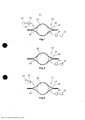
[015] As modalidades de execução da presente invenção serão explicadas com mais detalhes a seguir, com referência às Figuras. Nas Figuras: - a Figura 1 ilustra uma modalidade de execução da presente invenção com um fornecimento contínuo de gás de transporte através de um meio transportador; - a Figura 2 ilustra uma modalidade de execução da presente invenção na qual os componentes liberados para fora da película são utilizados como um fluxo contínuo de gás de transporte, e; - a Figura 3 ilustra uma modalidade de execução da presente invenção para o fornecimento único de uma quantidade predeterminada de gás de transporte.[015] The embodiments of the present invention will be explained in more detail below, with reference to the Figures. In the Figures: - Figure 1 illustrates an embodiment of the present invention with a continuous supply of carrier gas through a conveyor means; - Figure 2 illustrates an embodiment of the present invention in which the components released from the film are used as a continuous flow of carrier gas, and; - Figure 3 illustrates an embodiment of the present invention for the single supply of a predetermined amount of carrier gas.
[016] Em cada uma das modalidades de execução da presente invenção, a câmara de película (10) é formada por duas camadas de películas (12), (14). As películas (12), (14) podem consistir de películas flexíveis colocadas umas sobres as outras de forma estanque nas suas regiões das bordas externas. O objeto de teste (16) encontra-se contido na câmara de película (10). O volume (18) da câmara de película na região externa ao objeto de teste (16) encontra-se conectado em um modo de transporte de gás a uma bomba de vácuo (20) para a evacuação da câmara de película. A quantidade de gás evacuado pela bomba de vácuo (20) é fornecida a um sensor de gás (22) para determinar a concentração do gás de teste na mistura do gás evacuado. O sensor de gás (22) pode consistir, por exemplo, de um espectrômetro de massa.[016] In each of the embodiments of the present invention, the film chamber (10) is formed by two layers of films (12), (14). The films (12), (14) may consist of flexible films placed on top of each other in a watertight manner in their outer edge regions. The test object (16) is contained in the film chamber (10). The volume (18) of the film chamber in the region external to the test object (16) is connected in a gas transport mode to a vacuum pump (20) for evacuating the film chamber. The amount of gas evacuated by the vacuum pump (20) is fed to a gas sensor (22) to determine the concentration of test gas in the evacuated gas mixture. The gas sensor (22) may consist, for example, of a mass spectrometer.
[017] Na primeira modalidade de execução da presente invenção ilustrada na Figura 1, o volume (18) da câmera de película encontra-se adicionalmente conectado em um modo de transporte de gás a uma bomba transportadora (24) e a uma fonte (26) de gás de transporte. A bomba transportadora (24) e as fontes (26) de gás de transporte formam um meio transportador (25) para o gás de transporte, para o fornecimento de um fluxo contínuo de gás de transporte para a câmara de película. A bomba transportadora (24) transporta o gás de transporte contido na fonte (26) de gás de transporte para o interior da câmara de película (10). Alternativamente, pode ser utilizado um regulador de pressão ao invés de uma bomba transportadora (24).[017] In the first embodiment of the present invention illustrated in Figure 1, the volume (18) of the film camera is additionally connected in a gas transport mode to a conveyor pump (24) and a source (26). ) of carrier gas. The carrier pump (24) and the carrier gas sources (26) form a carrier means (25) for the carrier gas to supply a continuous flow of carrier gas to the film chamber. The carrier pump (24) transports the carrier gas contained in the carrier gas source (26) into the film chamber (10). Alternatively, a pressure regulator may be used instead of a conveyor pump (24).
[018] A modalidade de execução ilustrada na Figura 2 difere da primeira modalidade de execução pelo fato de que nenhum meio de transporte para o gás de transporte é providenciado. Após a evacuação da câmara de película (10), os componentes de gases liberados das superfícies internas das paredes (12), (14) da câmara de película em função da permeação natural, são utilizados como gás de transporte. A permeação destes componentes de gases ocorre de forma constante.[018] The execution modality illustrated in Figure 2 differs from the first execution modality in that no means of transport for the transport gas is provided. After evacuating the film chamber (10), the gas components released from the inner surfaces of the walls (12), (14) of the film chamber as a function of natural permeation are used as carrier gas. The permeation of these gas components occurs constantly.
[019] A terceira modalidade de execução ilustrada na Figura 3 difere da primeira modalidade de execução pelo fato de o volume (18) da câmara de película não estar conectado a um meio transportador de gás, mas sim, conectado a uma fonte (28) de gás de transporte que apresenta um volume constante de gás de transporte (por exemplo, sob pressão atmosférica). Após a evacuação da câmara de película (10) com a utilização da bomba de vácuo (20), a válvula (30) presente na conexão de transporte de gás entre a fonte (28) de gás de transporte e a câmara de película (10) é aberta, fazendo com que o volume de gás de transporte flua abruptamente para o interior da câmara de película (10).[019] The third execution modality illustrated in Figure 3 differs from the first execution modality in that the volume (18) of the film chamber is not connected to a gas carrier medium, but connected to a source (28) of carrier gas that has a constant volume of carrier gas (e.g. under atmospheric pressure). After evacuating the film chamber (10) using the vacuum pump (20), the valve (30) present in the gas transport connection between the transport gas source (28) and the film chamber (10) ) is opened, causing the volume of carrier gas to flow abruptly into the film chamber (10).
[020] Para as três modalidades de execução, o método da presente invenção é executado da maneira descrita a seguir.[020] For the three embodiments, the method of the present invention is performed as described below.
[021] Na primeira modalidade de execução, o volume (18) da câmara de película é reduzido por meio da evacuação da câmara de película (10) com a utilização da bomba de vácuo (20). Subsequentemente, um fluxo reduzido de gás de transporte é fornecido continuamente para a câmara de película (10) utilizando o meio transportador (25) para o gás de transporte, enquanto o fluxo de gás retirado da câmara de película (10) por meio da bomba de vácuo (20) é analisado pelo sensor (22). O sensor (22) determina a concentração do gás de teste no fluxo de gás medido. No caso de um vazamento, o fluxo do gás medido contém uma mistura do gás de transporte e do gás de teste. A concentração c do gás de teste no fluxo do gás de transporte é de:
[022] Aqui, o primeiro termo representa a concentração do gás de teste através do vazamento, e o segundo termo representa a substituição da concentração inicialmente existente do gás de teste pelo gás de teste do vazamento. Pode-se escrever também:
[023] Na segunda modalidade de execução, o volume (18) da câmara de película é reduzido pela evacuação da câmara de película (10) com a utilização da bomba de vácuo (20). Em cada uma das modalidades de execução, o objeto de teste (16) foi enchido previamente com um gás de teste. Com a utilização da bomba de vácuo (20), um fluxo aproximadamente contínuo de gás é fornecido ao sensor (22). Neste caso, o gás escapando para o interior através da permeação das películas (12), (14) é utilizado como o gás de transporte. A proporção do gás de transporte neste fluxo de gás é determinada com a utilização do sensor (22).[023] In the second embodiment, the volume (18) of the film chamber is reduced by evacuating the film chamber (10) using the vacuum pump (20). In each of the execution modes, the test object (16) was previously filled with a test gas. Using the vacuum pump (20), an approximately continuous flow of gas is supplied to the sensor (22). In this case, the gas escaping inwards through the permeation of the films (12), (14) is used as the carrier gas. The proportion of carrier gas in this gas stream is determined using the sensor (22).
[024] Na terceira modalidade de execução da presente invenção, a válvula (30) é aberta após a evacuação da câmara de película (10). O volume do gás de transporte contido na fonte (28) de gás de transporte flui então para o interior da câmara de película (10). Depois de decorrido um tempo predeterminado de acumulação, no qual o gás de teste pode escapar para o volume (18) da câmara de película através de um possível vazamento no objeto de teste (16), o sensor (22) determina a concentração do gás de teste. O volume do gás de transporte proveniente da fonte (28) de gás de transporte pode ser fornecido ao volume (18) da câmara de película antes, durante ou após o tempo decorrido de acumulação.[024] In the third embodiment of the present invention, the valve (30) is opened after evacuating the film chamber (10). The volume of carrier gas contained in the carrier gas source (28) then flows into the film chamber (10). After a predetermined accumulation time has elapsed, in which the test gas can escape into the volume (18) of the film chamber through a possible leak in the test object (16), the sensor (22) determines the concentration of the gas. of test. The volume of carrier gas from the carrier gas source (28) may be supplied to the film chamber volume (18) before, during or after the elapsed accumulation time.
Claims (14)
Applications Claiming Priority (3)
| Application Number | Priority Date | Filing Date | Title |
|---|---|---|---|
| DE102014224799.3A DE102014224799A1 (en) | 2014-12-03 | 2014-12-03 | Leak test with carrier gas in foil chamber |
| DE102014224799.3 | 2014-12-03 | ||
| PCT/EP2015/077636 WO2016087280A1 (en) | 2014-12-03 | 2015-11-25 | Leak-tightness test with carrier gas in foil chamber |
Publications (2)
| Publication Number | Publication Date |
|---|---|
| BR112017010967A2 BR112017010967A2 (en) | 2018-02-14 |
| BR112017010967B1 true BR112017010967B1 (en) | 2022-06-07 |
Family
ID=54697598
Family Applications (1)
| Application Number | Title | Priority Date | Filing Date |
|---|---|---|---|
| BR112017010967-0A BR112017010967B1 (en) | 2014-12-03 | 2015-11-25 | Method of performing a leak test |
Country Status (9)
| Country | Link |
|---|---|
| US (1) | US11199468B2 (en) |
| EP (1) | EP3227655B1 (en) |
| JP (1) | JP6653703B2 (en) |
| CN (1) | CN107003204B (en) |
| AU (1) | AU2015357410B2 (en) |
| BR (1) | BR112017010967B1 (en) |
| DE (1) | DE102014224799A1 (en) |
| RU (1) | RU2699960C2 (en) |
| WO (1) | WO2016087280A1 (en) |
Families Citing this family (9)
| Publication number | Priority date | Publication date | Assignee | Title |
|---|---|---|---|---|
| DE102014205032A1 (en) * | 2014-03-18 | 2015-09-24 | Inficon Gmbh | Density increase measurement in foil chamber |
| DE102014224799A1 (en) | 2014-12-03 | 2016-06-09 | Inficon Gmbh | Leak test with carrier gas in foil chamber |
| US9915581B2 (en) * | 2016-03-31 | 2018-03-13 | Glttek Co., Ltd | Seal detecting device and means thereof |
| DE102017201004A1 (en) * | 2017-01-23 | 2018-07-26 | Inficon Gmbh | Foil chamber with double foil |
| AT16562U1 (en) | 2017-02-24 | 2020-01-15 | Mits Gmbh | Method for checking the tightness of a flexible container |
| GB201813448D0 (en) * | 2018-08-17 | 2018-10-03 | Cascade Tech Holdings Limited | Leak detection system and method |
| DE102019121462B4 (en) | 2019-08-08 | 2021-12-09 | Inficon Gmbh | Procedure for leak testing a liquid-filled test object |
| GB2599667B (en) * | 2020-10-08 | 2022-11-02 | Mccarthy Martin | Puncture detection |
| DE102021100147A1 (en) | 2021-01-07 | 2022-07-07 | Inficon Gmbh | Foil chamber with carrier gas supply and method |
Family Cites Families (33)
| Publication number | Priority date | Publication date | Assignee | Title |
|---|---|---|---|---|
| US3888111A (en) * | 1973-11-21 | 1975-06-10 | Gen Motors Corp | Sealed beam headlamp unit leak detection system |
| DE2533830A1 (en) * | 1975-07-29 | 1977-02-10 | Leybold Heraeus Gmbh & Co Kg | DEVICE FOR DETECTING LEAKS ON DUTIES WITH EASILY DEFORMABLE WALLS |
| JPS62112027A (en) * | 1985-11-11 | 1987-05-23 | Shinkosumosu Denki Kk | Detecting method for leak in container |
| JPH01227037A (en) * | 1988-03-08 | 1989-09-11 | Yamaha Corp | Vessel for leak tester |
| DE19642099A1 (en) * | 1996-10-12 | 1998-04-16 | Leybold Vakuum Gmbh | Testing the tightness of packaging |
| JP3688083B2 (en) * | 1996-12-26 | 2005-08-24 | 東洋自動機株式会社 | Seal inspection method and apparatus |
| US6082184A (en) * | 1997-05-27 | 2000-07-04 | Martin Lehmann | Method for leak testing and leak testing apparatus |
| DE19935293A1 (en) * | 1999-07-27 | 2001-02-01 | Leybold Vakuum Gmbh | Foil leak detection chamber |
| US6584828B2 (en) * | 1999-12-17 | 2003-07-01 | Atc, Inc. | Method and apparatus of nondestructive testing a sealed product for leaks |
| DE50015394D1 (en) * | 1999-12-22 | 2008-11-20 | Inficon Gmbh | METHOD FOR OPERATING A FOIL LEAK DETECTOR AND FILM LEAK DETECTOR SUITABLE FOR CARRYING OUT THIS PROCEDURE |
| KR100828963B1 (en) | 2000-08-11 | 2008-05-14 | 로베르트 보쉬 게엠베하 | Knock recognition in internal combustion engines with modifications by changing filter characteristics or cylinder specific changes |
| DE10040074A1 (en) * | 2000-08-16 | 2002-02-28 | Inficon Gmbh | Method and device for leak testing a gas generator |
| US6513366B1 (en) * | 2001-10-11 | 2003-02-04 | Packaging Technologies & Inspection Llc | Method and apparatus for package leak testing |
| JP2003240668A (en) * | 2002-02-20 | 2003-08-27 | Honda Motor Co Ltd | Leakage testing device |
| US20040159144A1 (en) * | 2003-02-14 | 2004-08-19 | Thomas Abelen | Method and device for performing a leak test on a gas generator |
| JP4374241B2 (en) * | 2003-12-05 | 2009-12-02 | アディクセン スカンディナビア エービー | System and method for measuring the sealability of an object |
| EP1709412B1 (en) * | 2003-12-05 | 2008-04-16 | Adixen Sensistor AB | System and method for determining the leakproofness of an object |
| DE102007057944A1 (en) * | 2007-12-01 | 2009-06-04 | Inficon Gmbh | Method and device for leak testing |
| JP5370107B2 (en) | 2009-12-01 | 2013-12-18 | 凸版印刷株式会社 | Product pass / fail judgment device and product pass / fail judgment method |
| JP2011179975A (en) * | 2010-03-01 | 2011-09-15 | Ts:Kk | Device and method for inspecting leakage |
| US20120037795A1 (en) * | 2010-08-10 | 2012-02-16 | Martin Lehmann | Method and apparatuses for quality evaluation and leak testing |
| JP2012047651A (en) * | 2010-08-30 | 2012-03-08 | Anest Iwata Corp | Leak detector |
| US8806919B2 (en) * | 2011-07-29 | 2014-08-19 | Vacuum Technology Inc. | Leak detection apparatus and method |
| US10845266B2 (en) * | 2011-11-16 | 2020-11-24 | Inficon Gmbh | Quick leak detection on dimensionally stable/slack packaging without the addition of test gas |
| DE102011086486B4 (en) * | 2011-11-16 | 2023-01-19 | Inficon Gmbh | Device and method for rapid leak detection on dimensionally stable/slack packaging without the addition of tracer gas |
| DE102012200063A1 (en) * | 2012-01-03 | 2013-07-04 | Inficon Gmbh | Procedure for leak detection on a non-rigid specimen |
| DE102012220483A1 (en) * | 2012-11-09 | 2014-05-15 | Inficon Gmbh | Leak tester |
| DE102013217288A1 (en) * | 2013-08-29 | 2015-03-05 | Inficon Gmbh | Tightness test during the evacuation of a foil chamber |
| DE102013219464A1 (en) * | 2013-09-26 | 2015-03-26 | Inficon Gmbh | Evacuation of a foil chamber |
| CN103822761B (en) * | 2014-01-03 | 2017-01-04 | 中国空间技术研究院 | Device for detecting sealability and method |
| DE102014205032A1 (en) * | 2014-03-18 | 2015-09-24 | Inficon Gmbh | Density increase measurement in foil chamber |
| DE102014211228A1 (en) * | 2014-06-12 | 2015-12-17 | Inficon Gmbh | Differential pressure measurement with foil chamber |
| DE102014224799A1 (en) | 2014-12-03 | 2016-06-09 | Inficon Gmbh | Leak test with carrier gas in foil chamber |
-
2014
- 2014-12-03 DE DE102014224799.3A patent/DE102014224799A1/en not_active Withdrawn
-
2015
- 2015-11-25 JP JP2017529332A patent/JP6653703B2/en active Active
- 2015-11-25 BR BR112017010967-0A patent/BR112017010967B1/en active IP Right Grant
- 2015-11-25 EP EP15798484.0A patent/EP3227655B1/en active Active
- 2015-11-25 WO PCT/EP2015/077636 patent/WO2016087280A1/en active Application Filing
- 2015-11-25 US US15/532,423 patent/US11199468B2/en active Active
- 2015-11-25 RU RU2017122386A patent/RU2699960C2/en active
- 2015-11-25 AU AU2015357410A patent/AU2015357410B2/en active Active
- 2015-11-25 CN CN201580064453.3A patent/CN107003204B/en active Active
Also Published As
| Publication number | Publication date |
|---|---|
| JP2018501475A (en) | 2018-01-18 |
| EP3227655A1 (en) | 2017-10-11 |
| JP6653703B2 (en) | 2020-02-26 |
| US20170268957A1 (en) | 2017-09-21 |
| CN107003204B (en) | 2020-03-03 |
| RU2017122386A (en) | 2019-01-09 |
| CN107003204A (en) | 2017-08-01 |
| WO2016087280A1 (en) | 2016-06-09 |
| AU2015357410B2 (en) | 2020-08-27 |
| EP3227655B1 (en) | 2020-01-08 |
| RU2017122386A3 (en) | 2019-03-12 |
| DE102014224799A1 (en) | 2016-06-09 |
| RU2699960C2 (en) | 2019-09-11 |
| AU2015357410A1 (en) | 2017-06-15 |
| US11199468B2 (en) | 2021-12-14 |
| BR112017010967A2 (en) | 2018-02-14 |
Similar Documents
| Publication | Publication Date | Title |
|---|---|---|
| BR112017010967B1 (en) | Method of performing a leak test | |
| ES2665764T3 (en) | Vacuum state at rest for procedure and tightness test system by means of vacuum reduction measurement | |
| JP6457813B2 (en) | Rapid detection of dimensionally stable / loose package leaks without the addition of a test gas | |
| US10670489B2 (en) | Device and method for calibrating a film chamber for leak detection | |
| US11105704B2 (en) | Method and apparatus for an integrity test of a flexible container with inspection fluid | |
| JP6602852B2 (en) | Film chamber with volumetric function for gross leak detection | |
| JP6492084B2 (en) | Sealing test method when evacuating film chamber | |
| US10514317B2 (en) | Gas density increase measurement in a film chamber | |
| US7571636B2 (en) | Detecting and reporting the location of a leak in hermetically sealed packaging | |
| PT1626275E (en) | Method for determining the shelf-life of a packed product | |
| JP2016529503A5 (en) | ||
| JP6732536B2 (en) | Evaluation method and evaluation device for sealed inspection target | |
| US20180372579A1 (en) | Gross leak measurement in an incompressible test item in a film chamber | |
| TW201734424A (en) | Leakage inspection method and leakage inspection device for container to be inspected | |
| US20150276541A1 (en) | Method for Testing a Leakage Detection System | |
| Kossinna et al. | Helium leak testing of packages for oral drug products | |
| KR20150079973A (en) | Device and method for estimating a flow of gas in an enclosure maintained at reduced pressure in relation to the gas | |
| JP2003294570A (en) | Air leak measuring device | |
| JP5555923B2 (en) | Gas concentration measurement method for packaging machines | |
| JP2004157035A (en) | Gas permeation speed measuring device of barrier film-coated plastic container, gas permeation speed measuring method of barrier film-coated plastic container, gas permeation speed measuring device of barrier film-coated plastic sheet, and gas pearmeation speed measuring method of barrier film-coated plastic sheet | |
| US6634215B1 (en) | Method for integrally detecting leaks in test pieces with relatively thin walls | |
| EP1178297A1 (en) | A method for the continous detection of micro-leaks in packages of products in modified atmosphere and a device for said detection | |
| Fu et al. | Non-destructive detection technology for air-tightness of cigarette packets and the application in the research of moisture migration behavior | |
| JP2007121012A (en) | Pinhole inspection device of sealed package | |
| BR102023002997A2 (en) | AN APPARATUS FOR DETECTING A GAS LEAK AND A METHOD AND SYSTEM THEREOF |
Legal Events
| Date | Code | Title | Description |
|---|---|---|---|
| B06U | Preliminary requirement: requests with searches performed by other patent offices: procedure suspended [chapter 6.21 patent gazette] | ||
| B09A | Decision: intention to grant [chapter 9.1 patent gazette] | ||
| B16A | Patent or certificate of addition of invention granted [chapter 16.1 patent gazette] |
Free format text: PRAZO DE VALIDADE: 20 (VINTE) ANOS CONTADOS A PARTIR DE 25/11/2015, OBSERVADAS AS CONDICOES LEGAIS |