BR112017008423B1 - MITRAL VALVE REPLACEMENT SYSTEMS FOR A HEART AND PROSTHETIC MITRAL VALVE SYSTEM - Google Patents
MITRAL VALVE REPLACEMENT SYSTEMS FOR A HEART AND PROSTHETIC MITRAL VALVE SYSTEM Download PDFInfo
- Publication number
- BR112017008423B1 BR112017008423B1 BR112017008423-6A BR112017008423A BR112017008423B1 BR 112017008423 B1 BR112017008423 B1 BR 112017008423B1 BR 112017008423 A BR112017008423 A BR 112017008423A BR 112017008423 B1 BR112017008423 B1 BR 112017008423B1
- Authority
- BR
- Brazil
- Prior art keywords
- valve
- assembly
- anchor assembly
- anchor
- mitral valve
- Prior art date
Links
Images


Classifications
-
- A—HUMAN NECESSITIES
- A61—MEDICAL OR VETERINARY SCIENCE; HYGIENE
- A61F—FILTERS IMPLANTABLE INTO BLOOD VESSELS; PROSTHESES; DEVICES PROVIDING PATENCY TO, OR PREVENTING COLLAPSING OF, TUBULAR STRUCTURES OF THE BODY, e.g. STENTS; ORTHOPAEDIC, NURSING OR CONTRACEPTIVE DEVICES; FOMENTATION; TREATMENT OR PROTECTION OF EYES OR EARS; BANDAGES, DRESSINGS OR ABSORBENT PADS; FIRST-AID KITS
- A61F2/00—Filters implantable into blood vessels; Prostheses, i.e. artificial substitutes or replacements for parts of the body; Appliances for connecting them with the body; Devices providing patency to, or preventing collapsing of, tubular structures of the body, e.g. stents
- A61F2/02—Prostheses implantable into the body
- A61F2/24—Heart valves ; Vascular valves, e.g. venous valves; Heart implants, e.g. passive devices for improving the function of the native valve or the heart muscle; Transmyocardial revascularisation [TMR] devices; Valves implantable in the body
- A61F2/2442—Annuloplasty rings or inserts for correcting the valve shape; Implants for improving the function of a native heart valve
- A61F2/2445—Annuloplasty rings in direct contact with the valve annulus
- A61F2/2448—D-shaped rings
-
- A—HUMAN NECESSITIES
- A61—MEDICAL OR VETERINARY SCIENCE; HYGIENE
- A61F—FILTERS IMPLANTABLE INTO BLOOD VESSELS; PROSTHESES; DEVICES PROVIDING PATENCY TO, OR PREVENTING COLLAPSING OF, TUBULAR STRUCTURES OF THE BODY, e.g. STENTS; ORTHOPAEDIC, NURSING OR CONTRACEPTIVE DEVICES; FOMENTATION; TREATMENT OR PROTECTION OF EYES OR EARS; BANDAGES, DRESSINGS OR ABSORBENT PADS; FIRST-AID KITS
- A61F2/00—Filters implantable into blood vessels; Prostheses, i.e. artificial substitutes or replacements for parts of the body; Appliances for connecting them with the body; Devices providing patency to, or preventing collapsing of, tubular structures of the body, e.g. stents
- A61F2/02—Prostheses implantable into the body
- A61F2/24—Heart valves ; Vascular valves, e.g. venous valves; Heart implants, e.g. passive devices for improving the function of the native valve or the heart muscle; Transmyocardial revascularisation [TMR] devices; Valves implantable in the body
- A61F2/2403—Heart valves ; Vascular valves, e.g. venous valves; Heart implants, e.g. passive devices for improving the function of the native valve or the heart muscle; Transmyocardial revascularisation [TMR] devices; Valves implantable in the body with pivoting rigid closure members
-
- A—HUMAN NECESSITIES
- A61—MEDICAL OR VETERINARY SCIENCE; HYGIENE
- A61F—FILTERS IMPLANTABLE INTO BLOOD VESSELS; PROSTHESES; DEVICES PROVIDING PATENCY TO, OR PREVENTING COLLAPSING OF, TUBULAR STRUCTURES OF THE BODY, e.g. STENTS; ORTHOPAEDIC, NURSING OR CONTRACEPTIVE DEVICES; FOMENTATION; TREATMENT OR PROTECTION OF EYES OR EARS; BANDAGES, DRESSINGS OR ABSORBENT PADS; FIRST-AID KITS
- A61F2/00—Filters implantable into blood vessels; Prostheses, i.e. artificial substitutes or replacements for parts of the body; Appliances for connecting them with the body; Devices providing patency to, or preventing collapsing of, tubular structures of the body, e.g. stents
- A61F2/02—Prostheses implantable into the body
- A61F2/24—Heart valves ; Vascular valves, e.g. venous valves; Heart implants, e.g. passive devices for improving the function of the native valve or the heart muscle; Transmyocardial revascularisation [TMR] devices; Valves implantable in the body
- A61F2/2409—Support rings therefor, e.g. for connecting valves to tissue
-
- A—HUMAN NECESSITIES
- A61—MEDICAL OR VETERINARY SCIENCE; HYGIENE
- A61F—FILTERS IMPLANTABLE INTO BLOOD VESSELS; PROSTHESES; DEVICES PROVIDING PATENCY TO, OR PREVENTING COLLAPSING OF, TUBULAR STRUCTURES OF THE BODY, e.g. STENTS; ORTHOPAEDIC, NURSING OR CONTRACEPTIVE DEVICES; FOMENTATION; TREATMENT OR PROTECTION OF EYES OR EARS; BANDAGES, DRESSINGS OR ABSORBENT PADS; FIRST-AID KITS
- A61F2/00—Filters implantable into blood vessels; Prostheses, i.e. artificial substitutes or replacements for parts of the body; Appliances for connecting them with the body; Devices providing patency to, or preventing collapsing of, tubular structures of the body, e.g. stents
- A61F2/02—Prostheses implantable into the body
- A61F2/24—Heart valves ; Vascular valves, e.g. venous valves; Heart implants, e.g. passive devices for improving the function of the native valve or the heart muscle; Transmyocardial revascularisation [TMR] devices; Valves implantable in the body
- A61F2/2412—Heart valves ; Vascular valves, e.g. venous valves; Heart implants, e.g. passive devices for improving the function of the native valve or the heart muscle; Transmyocardial revascularisation [TMR] devices; Valves implantable in the body with soft flexible valve members, e.g. tissue valves shaped like natural valves
- A61F2/2418—Scaffolds therefor, e.g. support stents
-
- A—HUMAN NECESSITIES
- A61—MEDICAL OR VETERINARY SCIENCE; HYGIENE
- A61F—FILTERS IMPLANTABLE INTO BLOOD VESSELS; PROSTHESES; DEVICES PROVIDING PATENCY TO, OR PREVENTING COLLAPSING OF, TUBULAR STRUCTURES OF THE BODY, e.g. STENTS; ORTHOPAEDIC, NURSING OR CONTRACEPTIVE DEVICES; FOMENTATION; TREATMENT OR PROTECTION OF EYES OR EARS; BANDAGES, DRESSINGS OR ABSORBENT PADS; FIRST-AID KITS
- A61F2/00—Filters implantable into blood vessels; Prostheses, i.e. artificial substitutes or replacements for parts of the body; Appliances for connecting them with the body; Devices providing patency to, or preventing collapsing of, tubular structures of the body, e.g. stents
- A61F2/02—Prostheses implantable into the body
- A61F2/24—Heart valves ; Vascular valves, e.g. venous valves; Heart implants, e.g. passive devices for improving the function of the native valve or the heart muscle; Transmyocardial revascularisation [TMR] devices; Valves implantable in the body
- A61F2/2427—Devices for manipulating or deploying heart valves during implantation
- A61F2/2436—Deployment by retracting a sheath
-
- A—HUMAN NECESSITIES
- A61—MEDICAL OR VETERINARY SCIENCE; HYGIENE
- A61F—FILTERS IMPLANTABLE INTO BLOOD VESSELS; PROSTHESES; DEVICES PROVIDING PATENCY TO, OR PREVENTING COLLAPSING OF, TUBULAR STRUCTURES OF THE BODY, e.g. STENTS; ORTHOPAEDIC, NURSING OR CONTRACEPTIVE DEVICES; FOMENTATION; TREATMENT OR PROTECTION OF EYES OR EARS; BANDAGES, DRESSINGS OR ABSORBENT PADS; FIRST-AID KITS
- A61F2/00—Filters implantable into blood vessels; Prostheses, i.e. artificial substitutes or replacements for parts of the body; Appliances for connecting them with the body; Devices providing patency to, or preventing collapsing of, tubular structures of the body, e.g. stents
- A61F2/02—Prostheses implantable into the body
- A61F2/24—Heart valves ; Vascular valves, e.g. venous valves; Heart implants, e.g. passive devices for improving the function of the native valve or the heart muscle; Transmyocardial revascularisation [TMR] devices; Valves implantable in the body
- A61F2/2427—Devices for manipulating or deploying heart valves during implantation
- A61F2/2439—Expansion controlled by filaments
-
- A—HUMAN NECESSITIES
- A61—MEDICAL OR VETERINARY SCIENCE; HYGIENE
- A61F—FILTERS IMPLANTABLE INTO BLOOD VESSELS; PROSTHESES; DEVICES PROVIDING PATENCY TO, OR PREVENTING COLLAPSING OF, TUBULAR STRUCTURES OF THE BODY, e.g. STENTS; ORTHOPAEDIC, NURSING OR CONTRACEPTIVE DEVICES; FOMENTATION; TREATMENT OR PROTECTION OF EYES OR EARS; BANDAGES, DRESSINGS OR ABSORBENT PADS; FIRST-AID KITS
- A61F2230/00—Geometry of prostheses classified in groups A61F2/00 - A61F2/26 or A61F2/82 or A61F9/00 or A61F11/00 or subgroups thereof
- A61F2230/0063—Three-dimensional shapes
- A61F2230/0073—Quadric-shaped
- A61F2230/0078—Quadric-shaped hyperboloidal
-
- A—HUMAN NECESSITIES
- A61—MEDICAL OR VETERINARY SCIENCE; HYGIENE
- A61F—FILTERS IMPLANTABLE INTO BLOOD VESSELS; PROSTHESES; DEVICES PROVIDING PATENCY TO, OR PREVENTING COLLAPSING OF, TUBULAR STRUCTURES OF THE BODY, e.g. STENTS; ORTHOPAEDIC, NURSING OR CONTRACEPTIVE DEVICES; FOMENTATION; TREATMENT OR PROTECTION OF EYES OR EARS; BANDAGES, DRESSINGS OR ABSORBENT PADS; FIRST-AID KITS
- A61F2250/00—Special features of prostheses classified in groups A61F2/00 - A61F2/26 or A61F2/82 or A61F9/00 or A61F11/00 or subgroups thereof
- A61F2250/0058—Additional features; Implant or prostheses properties not otherwise provided for
- A61F2250/006—Additional features; Implant or prostheses properties not otherwise provided for modular
- A61F2250/0063—Nested prosthetic parts
Abstract
A presente invenção refere-se às válvulas mitrais prostésicas, que podem ser implementadas utilizando um sistema de administração de válvula mitral transcatéter e uma técnica para interagir e ancorar em cooperação com as estruturas anatômicas de uma válvula mitral nativa. Este pedido de patente descreve a prótese de válvulas cardíacas que interagem com as estruturas da válvula mitral nativa para criar um selo de fluido, minimizando assim a regurgitação mitral e os vazamentos paravalvulares. Este documento também descreve projetos protésicos de válvulas cardíacas e técnicas para gerenciar o fluxo sanguíneo através do trato de saída do ventrículo esquerdo. Além disso, este documento descreve protótipos de válvulas cardíacas e técnicas que reduzem o risco de interferência entre as válvulas protéticas e as cordas tendíneas.The present invention relates to prosthetic mitral valves, which can be implemented using a transcatheter mitral valve delivery system and a technique for interacting and anchoring in cooperation with the anatomical structures of a native mitral valve. This patent application describes prosthetic heart valves that interact with native mitral valve structures to create a fluid seal, thereby minimizing mitral regurgitation and paravalvular leaks. This document also describes prosthetic heart valve designs and techniques for managing blood flow through the left ventricular outflow tract. In addition, this document describes heart valve prototypes and techniques that reduce the risk of interference between prosthetic valves and chordae tendineae.
Description
[0001] Este pedido reivindica o benefício do Pedido U.S. Número de Série 62/067.907, depositado em 23 de outubro de 2014, Pedido U.S. Número de Série 14/671.577, depositado em 27 de março de 2015, Pedido U.S. Número de Série 14/673.055, depositado em 30 de Março de 2015, e Pedido U.S. Número de Série 14/674.349, depositado em 31 de Março 2015. A descrição dos pedidos anteriores é considerada parte da e está incorporada por referência na descrição deste pedido.[0001] This application claims the benefit of the U.S. Serial Number 62/067,907, filed October 23, 2014, U.S.
[0002] Este documento refere-se a válvulas cardíacas protéticas, tais como válvulas mitrais protéticas que podem ser implantadas utilizando técnicas de transcateter.[0002] This document relates to prosthetic heart valves, such as prosthetic mitral valves that can be implanted using transcatheter techniques.
[0003] O efeito clínico de longo prazo de regurgitação de válvula é reconhecido como um contribuidor significativo para morbidez e mortalidade relativas cardiovasculares. Assim, para muitas terapias destinadas a tratar a válvula mitral, um objetivo primário é significativamente reduzir ou eliminar a regurgitação. Eliminando a regurgitação na válvula mitral, os efeitos de sobrecarga de volume destrutivos sobre o ventrículo esquerdo podem ser atenuados. A sobrecarga de volume de regurgitação mitral (MR) refere-se à excessiva energia cinética requerida durante a contração isotônica para gerar o volume de batida total em uma tentativa de manter o volume de batida direto e rendimento cardíaco. Esta também refere-se à dissipação de energia potencial de pressão da válvula que vaza durante a maior porção de consumo de energia do ciclo cardíaco, a contração isovolumétrica. Além disso, as terapias para redução de MR podem ter o efeito de reduzir as pressões elevadas no átrio esquerdo e vasculatura pulmonar reduzindo o edema pulmonar (congestão) e sintomatologia de encurtamento de respiração. Tais terapias para redução de MR podem também ter um efeito positivo sobre o perfil de enchimento do ventrículo esquerdo (LV) e a fisiologia de LV restritiva que pode resultar com a MR. Estes problemas patofisiológicos indicam os benefícios potenciais de terapia de MR, mas também indicam a complexidade do sistema e a necessidade de uma terapia focalizar além do nível ou grau de MR.[0003] The long-term clinical effect of valve regurgitation is recognized as a significant contributor to cardiovascular relative morbidity and mortality. Thus, for many therapies aimed at treating the mitral valve, a primary goal is to significantly reduce or eliminate regurgitation. By eliminating mitral valve regurgitation, the destructive effects of volume overload on the left ventricle can be mitigated. Mitral regurgitation (MR) volume overload refers to the excessive kinetic energy required during isotonic contraction to generate total beat volume in an attempt to maintain direct beat volume and cardiac output. This also refers to the dissipation of pressure potential energy from the valve that leaks during the largest energy-consuming portion of the cardiac cycle, the isovolumetric contraction. In addition, MR-lowering therapies may have the effect of reducing elevated pressures in the left atrium and pulmonary vasculature by reducing pulmonary edema (congestion) and shortness of breath symptomatology. Such MR-lowering therapies may also have a positive effect on the left ventricular (LV) filling profile and restrictive LV physiology that can result with MR. These pathophysiological issues indicate the potential benefits of MR therapy, but also indicate the complexity of the system and the need for a therapy to focus beyond the level or grade of MR.
[0004] Algumas terapias para tratar a MR podem piorar outras doenças patológicas existentes (não MR) ou criar novas doenças patológicas. Uma das doenças a serem gerenciadas é a estenose mitral ou criação de um gradiente de influxo. Isto é, se um sistema de válvula protética for utilizado que não permite um suficiente Influxo de LV sem elevadas pressões de enchimento, então alguns benefícios de redução de MR podem ser dissipados ou perdidos. Uma doença adicional a ser gerenciada é a obstrução de trato de efluxo ventricular esquerdo (LVOT) ou a criação de altos gradientes de pressão de LVOT. Isto é, se um sistema de válvula protética for utilizado que significativamente obstrui o LVOT, então alguns benefícios de redução de MR podem ser dissipados ou perdidos. Também, se o procedimento resultar em danos ao tecido atrial na cirurgia, isto pode aumentar a probabilidade do efeito fisiológico negativo de fibrilação atrial. Ainda, alguns sistemas de válvula protética podem aumentar o risco de tensão de parede de LV mais alta através de um aumento no tamanho de LV (geometria de LV). Devido à relação integral da válvula mitral com a geometria de LV através do aparelho papilar ou cordal, os níveis de tensão de parede de LV podem ser diretamente afetados resultando em alterações da mecânica de enchimento e contração de LV. Consequentemente, em algumas circunstâncias, um sistema de válvula protética que piora a geometria do LV pode ir contra os benefícios de redução de MR devido à alteração de fisiologia contrátil.[0004] Some therapies to treat MR may worsen other existing (non-MR) pathological diseases or create new pathological diseases. One of the diseases to be managed is mitral stenosis or creating an inflow gradient. That is, if a prosthetic valve system is used that does not allow sufficient LV Inflow without high filling pressures, then some MR reduction benefits may be dissipated or lost. An additional disease to manage is left ventricular outflow tract (LVOT) obstruction or the creation of high LVOT pressure gradients. That is, if a prosthetic valve system is used that significantly obstructs the LVOT, then some MR reduction benefits may be dissipated or lost. Also, if the procedure results in damage to atrial tissue in surgery, this may increase the likelihood of the negative physiological effect of atrial fibrillation. Also, some prosthetic valve systems may increase the risk of higher LV wall tension through an increase in LV size (LV geometry). Due to the integral relationship of the mitral valve to the LV geometry through the papillary or chordal apparatus, the LV wall tension levels can be directly affected resulting in changes in the mechanics of LV filling and contraction. Consequently, in some circumstances, a prosthetic valve system that worsens LV geometry may counteract the MR reduction benefits due to altered contractile physiology.
[0005] Este documento descreve válvulas cardíacas protéticas, tal como válvulas mitrais protéticas que podem ser implantadas utilizando técnicas de transcateter. Por exemplo, algumas modalidades de um sistema e método de aplicação de válvula mitral de transcateter aqui descritos podem ser posicionados para interfacear e ancorar em cooperação com as estruturas anatômicas nativas de uma válvula mitral. Além disso, este documento descreve sistemas de válvula cardíaca protética que interfaceiam com estruturas de válvula mitral nativa para criar uma vedação de fluido, por meio disto minimizando a MR e vazamentos paravalvulares após a implantação. Ainda, este documento descreve sistemas e técnicas de válvula cardíaca protética e que, em modalidades específicas, estão configurados para gerenciar o fluxo sanguíneo através do trato de efluxo ventricular esquerdo (LVOT) e para por meio disto reduzir o risco de bloqueios totais ou parciais do LVOT. Além disso, algumas modalidades dos sistemas e técnicas de válvula cardíaca protética aqui descritas podem estar configuradas para reduzir o risco de interferência entre as válvulas protéticas e as chordae tendineae dos folículos de válvula mitral nativa, o que pode vantajosamente facilitar ou preservar a geometria do LV.[0005] This document describes prosthetic heart valves such as prosthetic mitral valves that can be implanted using transcatheter techniques. For example, some embodiments of a transcatheter mitral valve delivery system and method described herein may be positioned to interface and anchor in cooperation with the native anatomical structures of a mitral valve. In addition, this document describes prosthetic heart valve systems that interface with native mitral valve structures to create a fluid seal, thereby minimizing MR and paravalvular leakage after implantation. Furthermore, this document describes prosthetic heart valve systems and techniques that, in specific modalities, are configured to manage blood flow through the left ventricular outflow tract (LVOT) and thereby reduce the risk of total or partial blockage of the heart. LVOT In addition, some modalities of the prosthetic heart valve systems and techniques described herein may be configured to reduce the risk of interference between the prosthetic valves and the chordae tendineae of native mitral valve follicles, which may advantageously facilitate or preserve LV geometry. .
[0006] Modalidades específicas aqui descritas incluem um sistema de substituição de válvula mitral para um coração. O sistema pode incluir um conjunto de âncora expansível configurado para implante em uma válvula mitral nativa, e o conjunto de âncora expansível pode incluir uma primeira estrutura expansível que é ajustável de uma condição de aplicação para uma condição expandida. O sistema pode também incluir uma bainha de aplicação de primeiro dispositivo que tem uma extremidade mais distante inserível em um átrio esquerdo e sendo configurado para expelir o conjunto de âncora para fora da extremidade mais distante de modo que o conjunto de âncora expanda dentro do átrio esquerdo para a condição expandida. Opcionalmente, o sistema pode ainda incluir um instrumento empurrador liberavelmente fixável na estrutura de âncora expansível e sendo configurado para longitudinalmente avançar o conjunto de âncora dentro do átrio esquerdo na direção de um ânulo da válvula mitral nativa enquanto o conjunto de âncora está na condição expandida. Também, o sistema pode incluir um conjunto de válvula artificial que compreende uma segunda estrutura expansível que é ajustável de uma condição comprimida para uma condição posicionada para seletivamente acoplar com o conjunto de âncora enquanto o conjunto de âncora está na condição expandida.[0006] Specific modalities described herein include a mitral valve replacement system for a heart. The system may include an expandable anchor assembly configured for implantation into a native mitral valve, and the expandable anchor assembly may include a first expandable structure that is adjustable from an application condition to an expanded condition. The system may also include a first device delivery sheath having a distal end insertable into a left atrium and being configured to expel the anchor assembly out of the distal end so that the anchor assembly expands into the left atrium. for the expanded condition. Optionally, the system may further include a pusher instrument releasably attachable to the expandable anchor structure and being configured to longitudinally advance the anchor assembly within the left atrium towards a native mitral valve annulus while the anchor assembly is in the expanded condition. Also, the system may include an artificial valve assembly comprising a second expandable structure that is adjustable from a compressed condition to a positioned condition to selectively engage with the anchor assembly while the anchor assembly is in the expanded condition.
[0007] Algumas modalidades aqui descritas incluem um método para posicionar um sistema de válvula mitral protética dentro de uma válvula mitral nativa de um paciente. O método pode incluir navegar uma primeira bainha de aplicação dentro do paciente de modo que uma extremidade mais distante da primeira bainha de aplicação esteja posicionada dentro de um átrio esquerdo. O método pode também incluir expelir um conjunto de âncora do sistema de válvula cardíaca protética da extremidade mais distante da primeira bainha de aplicação de modo que o conjunto de âncora pelo menos parcialmente expanda enquanto localizado dentro do átrio esquerdo. Ainda, o método pode incluir, após expelir o conjunto de âncora dentro do átrio esquerdo, mover o conjunto de âncora na direção de um ânulo da válvula mitral nativa.[0007] Some embodiments described herein include a method for positioning a prosthetic mitral valve system within a patient's native mitral valve. The method may include navigating a first delivery sheath within the patient so that a distal end of the first delivery sheath is positioned within a left atrium. The method may also include expelling a prosthetic heart valve system anchor assembly from the far end of the first delivery sheath so that the anchor assembly at least partially expands while located within the left atrium. Further, the method may include, after expelling the anchor assembly into the left atrium, moving the anchor assembly towards a native mitral valve annulus.
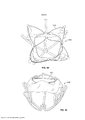
[0008] Várias modalidades aqui descritas incluem um sistema de válvula mitral protética. O sistema pode incluir um conjunto de válvula, o qual pode incluir um membro de estrutura que define um perfil externo e um espaço de membro de estrutura interno, e um oclusor disposto dentro do espaço de membro de estrutura interno. O oclusor pode ter uma configuração aberta e uma configuração fechada. O membro de estrutura compreende uma porção de estrutura de extremidade mais próxima e uma porção de estrutura de extremidade mais distante. Opcionalmente, uma periferia externa da porção de estrutura de extremidade mais distante pode incluir uma região geralmente plana e uma região geralmente redonda, e pelo menos algumas porções da região geralmente plana podem estender na direção do espaço de membro de estrutura interno.[0008] Various embodiments described herein include a prosthetic mitral valve system. The system may include a valve assembly, which may include a frame member defining an outer profile and an inner frame member space, and an occluder disposed within the inner frame member space. The occluder can have an open configuration and a closed configuration. The frame member comprises a nearer end frame portion and a far end frame portion. Optionally, an outer periphery of the far-end frame portion may include a generally flat region and a generally round region, and at least some portions of the generally flat region may extend toward the inner frame member space.
[0009] Modalidades específicas aqui descritas incluem um método para utilizar um sistema de válvula mitral protética. O método pode incluir avançar um conjunto de válvula do sistema de válvula mitral protética na direção de um ânulo de uma válvula mitral nativa. Opcionalmente, o conjunto de válvula pode incluir um membro de estrutura que define um perfil externo e um espaço de membro de estrutura interno, e um oclusor disposto dentro do espaço de membro de estrutura interno. O membro de estrutura pode incluir uma porção de estrutura de extremidade mais próxima e uma porção de estrutura de extremidade mais distante. Uma periferia externa da porção de estrutura de extremidade mais distante pode opcionalmente incluir uma região geralmente plana e uma região geralmente redonda, e pelo menos algumas porções da região geralmente plana estendem na direção do espaço de membro de estrutura interno. O método pode também incluir ancorar o conjunto de válvula na válvula mitral nativa de modo que a região geralmente plana fique adjacente a um folículo nativo anterior da válvula mitral nativa.[0009] Specific embodiments described herein include a method for utilizing a prosthetic mitral valve system. The method may include advancing a valve assembly of the prosthetic mitral valve system toward an annulus of a native mitral valve. Optionally, the valve assembly may include a frame member defining an outer profile and an inner frame member space, and an occluder disposed within the inner frame member space. The frame member may include a nearer end frame portion and a far end frame portion. An outer periphery of the far-end frame portion may optionally include a generally flat region and a generally round region, and at least some portions of the generally flat region extend toward the inner frame member space. The method may also include anchoring the valve assembly to the native mitral valve so that the generally flat region is adjacent to a native follicle anterior to the native mitral valve.
[00010] Algumas modalidades aqui descritas incluem um sistema de válvula mitral protética que é implantável em uma válvula mitral nativa. O sistema de válvula mitral protética pode incluir um conjunto de âncora que define um espaço de conjunto de âncora interno e eixo geométrico longitudinal. O conjunto de âncora pode incluir uma estrutura de âncora expansível que inclui um cubo e um braço de suporte subanular que estende do cubo. O braço de suporte subanular pode estender para um pé de âncora que tem uma superfície configurada para acoplamento com uma canaleta subanular da válvula mitral nativa. O sistema pode ainda incluir um conjunto de válvula que inclui uma estrutura de válvula expansível que define um perfil externo e um espaço de membro de estrutura interno, e um oclusor disposto dentro do espaço de membro de estrutura interno. O conjunto de válvula pode ser acoplável liberável com o conjunto de âncora dentro do espaço de conjunto de âncora interno. Opcionalmente, uma distância medida paralela ao eixo geométrico longitudinal de uma extremidade mais distante do conjunto de âncora para a superfície é pelo menos 14 milímetros.[00010] Some embodiments described herein include a prosthetic mitral valve system that is implantable in a native mitral valve. The prosthetic mitral valve system may include an anchor assembly that defines an internal anchor assembly space and longitudinal axis. The anchor assembly may include an expandable anchor structure that includes a hub and a sub-annular support arm extending from the hub. The subannular support arm may extend to an anchor foot that has a surface configured for engagement with a subannular groove of the native mitral valve. The system may further include a valve assembly that includes an expandable valve frame defining an outer profile and an inner frame member space, and an occluder disposed within the inner frame member space. The valve assembly may be releasably attachable with the anchor assembly within the internal anchor assembly space. Optionally, a distance measured parallel to the longitudinal axis of the furthest end of the anchor assembly to the surface is at least 14 millimeters.
[00011] Várias modalidades aqui descritas incluem um método para utilizar um sistema de válvula mitral protética. O método pode incluir avançar um conjunto de âncora do sistema de válvula mitral protética na direção de um ânulo de uma válvula mitral nativa. O conjunto de âncora pode ter um espaço de conjunto de âncora interno e um eixo geométrico longitudinal, e o conjunto de âncora pode incluir uma estrutura de âncora expansível que inclui um cubo e um ou mais braços de suporte subanulares que estendem do cubo. Cada um dos um ou mais braços de suporte subanulares pode estender para um pé de âncora configurado para acoplar com uma canaleta subanular da válvula mitral nativa. O método pode ainda incluir acoplar o conjunto de âncora do sistema de válvula mitral protética com o tecido próximo da válvula mitral nativa de modo que cada pé de âncora seja acoplado com a canaleta subanular, e (opcionalmente) de modo que o cubo fique posicionado mais distante da área de coaptação mais distante entre folículos anterior e posterior da válvula mitral nativa.[00011] Various embodiments described herein include a method of utilizing a prosthetic mitral valve system. The method may include advancing a prosthetic mitral valve system anchor assembly toward an annulus of a native mitral valve. The anchor assembly can have an internal anchor assembly space and a longitudinal axis, and the anchor assembly can include an expandable anchor structure that includes a hub and one or more sub-annular support arms extending from the hub. Each of the one or more subannular support arms may extend to an anchor foot configured to mate with a subannular channel of the native mitral valve. The method may further include mating the prosthetic mitral valve system anchor assembly with tissue near the native mitral valve so that each anchor foot is mated with the subannular groove, and (optionally) so that the hub is positioned further distant from the most distant area of coaptation between anterior and posterior follicles of the native mitral valve.
[00012] Modalidades específicas aqui descritas incluem um método para vedar entre um sistema de válvula mitral protética e folículos nativos de uma válvula mitral. O método pode incluir ancorar um conjunto de âncora do sistema de válvula mitral protética com o tecido mais próximo de um ânulo de uma válvula mitral nativa. Opcionalmente, o conjunto de âncora define um espaço de conjunto de âncora interno e um eixo geométrico longitudinal, e o conjunto de âncora pode incluir uma estrutura de âncora expansível que inclui um cubo e um ou mais braços de suporte subanulares que estendem do cubo. Cada um dos um ou mais braços de suporte subanular pode estender para um pé de âncora que acopla com uma canaleta subanular da válvula mitral nativa. O método pode ainda incluir aplicar um conjunto de válvula do sistema de válvula mitral protética para acoplar com o conjunto de âncora. Opcionalmente, o conjunto de válvula pode incluir: uma estrutura de válvula expansível que define um perfil externo e um espaço de membro de estrutura interno, uma camada de tecido disposta sobre pelo menos uma porção do perfil externo, e um oclusor disposto dentro do espaço de membro de estrutura interno. A camada de tecido do conjunto de válvula pode topar com os folículos nativos da válvula mitral enquanto cada pé de âncora do conjunto de âncora está acoplado com a canaleta subanular.[00012] Specific embodiments described herein include a method for sealing between a prosthetic mitral valve system and native follicles of a mitral valve. The method may include anchoring a prosthetic mitral valve system anchor assembly with tissue closest to an annulus of a native mitral valve. Optionally, the anchor assembly defines an internal anchor assembly space and a longitudinal axis, and the anchor assembly may include an expandable anchor structure that includes a hub and one or more sub-annular support arms extending from the hub. Each of the one or more subannular support arms can extend to an anchor foot that mates with a subannular channel of the native mitral valve. The method may further include applying a valve assembly from the prosthetic mitral valve system to mate with the anchor assembly. Optionally, the valve assembly may include: an expandable valve structure that defines an external profile and an internal structure member space, a tissue layer disposed over at least a portion of the external profile, and an occluder disposed within the cavity space. internal structure member. The tissue layer of the valve assembly can abut the native follicles of the mitral valve while each anchor foot of the anchor assembly is coupled with the subannular channel.
[00013] Algumas modalidades aqui descritas incluem um sistema de válvula mitral protética. O sistema pode incluir um conjunto de âncora que compreende uma estrutura de âncora expansível e um conjunto de pés de âncora subanulares configurado para acoplar com a canaleta subanular da válvula mitral nativa. O sistema pode ainda incluir um conjunto de válvula que inclui: uma estrutura de válvula expansível que define um perfil externo e um espaço de membro de estrutura interno, uma camada de tecido disposta sobre pelo menos uma porção do perfil externo, e um oclusor montado dentro do espaço de membro de estrutura interno. Opcionalmente, uma periferia que faceia para fora da camada de tecido ao longo do conjunto de válvula está posicionada para topar nos folículos nativos da válvula mitral quando o conjunto de pés de âncora do conjunto de âncora está acoplado com a canaleta subanular.[00013] Some embodiments described herein include a prosthetic mitral valve system. The system may include an anchor assembly comprising an expandable anchor structure and a set of subannular anchor feet configured to mate with the subannular groove of the native mitral valve. The system may further include a valve assembly that includes: an expandable valve structure that defines an external profile and an internal structure member space, a tissue layer disposed over at least a portion of the external profile, and an occluder mounted inside. of the inner frame member space. Optionally, an outward facing periphery of the tissue layer along the valve assembly is positioned to abut the native follicles of the mitral valve when the anchor feet assembly of the anchor assembly is coupled with the subannular channel.
[00014] Várias modalidades aqui descritas incluem um método para posicionar um sistema de válvula mitral protética dentro de uma válvula mitral nativa de um paciente. O método pode compreender navegar uma bainha de aplicação de modo que uma extremidade mais distante da bainha de aplicação seja posicionada dentro de um átrio esquerdo do paciente. Também, o método pode incluir expelir, dentro do átrio esquerdo, um conjunto de âncora do sistema de válvula mitral protética. Um instrumento empurrador mais distante pode estar acoplado liberável com o conjunto de âncora. O método pode ainda incluir acoplar o conjunto de âncora com a válvula mitral nativa enquanto o instrumento empurrador mais distante permanece acoplado com o conjunto de âncora. O método pode também incluir expelir, dentro do átrio esquerdo, um conjunto de válvula do sistema de válvula mitral protética. Opcionalmente, o conjunto de válvula pode ser acoplado deslizante com um exterior do instrumento empurrador mais distante. O método pode ainda incluir mover o conjunto de válvula para dentro de um espaço interno definido pelo conjunto de âncora. O movimento pode opcionalmente incluir deslizar o conjunto de válvula ao longo do exterior do cateter empurrador mais distante enquanto o cateter empurrador mais distante permanece acoplado com o conjunto de âncora. O método pode também incluir, após mover o conjunto de válvula, montar o conjunto de válvula com o conjunto de âncora. Ainda, o método pode incluir, após montar o conjunto de válvula, desacoplar o instrumento empurrador mais distante do conjunto de âncora.[00014] Various embodiments described herein include a method for positioning a prosthetic mitral valve system within a patient's native mitral valve. The method may comprise navigating a delivery sheath so that a distal end of the delivery sheath is positioned within a patient's left atrium. Also, the method may include expelling, into the left atrium, a prosthetic mitral valve system anchor assembly. A more distant pushing instrument may be releasably coupled with the anchor assembly. The method may further include coupling the anchor assembly with the native mitral valve while the farthest pushing instrument remains coupled with the anchor assembly. The method may also include expelling, into the left atrium, a valve assembly of the prosthetic mitral valve system. Optionally, the valve assembly may be slip-coupled with a farther exterior of the pusher instrument. The method may further include moving the valve assembly into an internal space defined by the anchor assembly. The movement may optionally include sliding the valve assembly along the exterior of the furthest pusher catheter while the furthest pusher catheter remains coupled with the anchor assembly. The method may also include, after moving the valve assembly, assembling the valve assembly with the anchor assembly. Further, the method may include, after assembling the valve assembly, decoupling the pusher instrument furthest from the anchor assembly.
[00015] Modalidades específicas aqui descritas incluem um sistema de aplicação de dispositivo médico implantável. O sistema pode incluir um primeiro cateter flexionável que define um primeiro lúmen através do mesmo, e uma porção de extremidade mais distante do primeiro cateter flexionável pode ser controlavelmente lateralmente flexionável. O sistema pode também incluir uma primeira bainha de aplicação de dispositivo disponível deslizante dentro do primeiro lúmen, e a primeira bainha de aplicação de dispositivo pode definir um segundo lúmen através da mesma. O sistema pode ainda incluir uma bainha de controle de primeiro dispositivo disponível deslizante dentro do segundo lúmen, e a bainha de controle de primeiro dispositivo pode definir um terceiro lúmen através da mesma e um ou mais lúmens de fio de controle de primeiro dispositivo. O sistema pode também incluir um segundo cateter flexionável disponível deslizante dentro do terceiro lúmen, e o segundo cateter flexionável pode definir um quarto lúmen através do mesmo. Uma porção de extremidade mais distante do segundo cateter flexionável pode ser controlavelmente lateralmente flexionável. O sistema pode ainda incluir um cateter empurrador de dispositivo disponível deslizante dentro do quarto lúmen, e o cateter empurrador de dispositivo pode definir um quinto lúmen através do mesmo. Uma porção de extremidade mais distante DO cateter empurrador de dispositivo pode estar configurada para acoplar liberável com um primeiro dispositivo médico implantável.[00015] Specific embodiments described herein include an implantable medical device delivery system. The system may include a first flexible catheter defining a first lumen therethrough, and a distal end portion of the first flexible catheter may be controllably laterally flexible. The system may also include a first available device delivery sheath sliding within the first lumen, and the first delivery device sheath may define a second lumen therethrough. The system may further include a first available device control sheath sliding within the second lumen, and the first device control sheath may define a third lumen therethrough and one or more first device control wire lumens. The system may also include a second flexible catheter available sliding within the third lumen, and the second flexible catheter may define a fourth lumen therethrough. A distal end portion of the second flexible catheter may be controllably laterally flexible. The system may further include an available device-pusher catheter slidable within the fourth lumen, and the device-pusher catheter may define a fifth lumen therethrough. A distal end portion of the device pushing catheter may be configured to releasably couple with a first implantable medical device.
[00016] Algumas modalidades aqui descritas incluem um método para posicionar um sistema de válvula mitral protética dentro de uma válvula mitral nativa de um paciente. O método pode incluir expandir um conjunto de âncora do sistema de válvula cardíaca protética dentro de um átrio esquerdo, enquanto o conjunto de âncora está preso liberável em um primeiro cateter de aplicação, de modo que o conjunto de âncora pelo menos parcialmente expande enquanto localizado dentro do átrio esquerdo. O método pode opcionalmente incluir, após expelir o conjunto de âncora dentro do átrio esquerdo, girar ou rodar o conjunto de âncora dentro do átrio esquerdo articulando uma porção de ponta do primeiro cateter de aplicação.[00016] Some embodiments described herein include a method for positioning a prosthetic mitral valve system within a patient's native mitral valve. The method may include expanding a prosthetic heart valve system anchor assembly within a left atrium, while the anchor assembly is releasably attached to a first delivery catheter such that the anchor assembly at least partially expands while located within of the left atrium. The method may optionally include, after expelling the anchor assembly within the left atrium, rotating or rotating the anchor assembly within the left atrium articulating a tip portion of the first delivery catheter.
[00017] Várias modalidades aqui descritas incluem um método para posicionar um sistema de válvula mitral protética dentro de uma válvula mitral nativa de um paciente. O método pode incluir expelir um conjunto de válvula do sistema de válvula cardíaca protética dentro de um átrio esquerdo, enquanto o conjunto de válvula está preso liberável em um cateter de aplicação de válvula, de modo que o conjunto de válvula pelo menos parcialmente expande enquanto localizado dentro do átrio esquerdo. O método pode opcionalmente incluir, após expelir o conjunto de válvula dentro do átrio esquerdo, girar ou rodar o conjunto de válvula dentro do átrio esquerdo articulando uma porção de ponta do cateter de aplicação de válvula.[00017] Various embodiments described herein include a method for positioning a prosthetic mitral valve system within a patient's native mitral valve. The method may include expelling a valve assembly from the prosthetic heart valve system into a left atrium while the valve assembly is releasably attached to a valve delivery catheter such that the valve assembly at least partially expands while located. inside the left atrium. The method may optionally include, after expelling the valve assembly into the left atrium, rotating or rotating the valve assembly into the left atrium by articulating a tip portion of the valve delivery catheter.
[00018] Algumas ou todas as modalidades aqui descritas podem prover uma ou mais das seguintes vantagens. Primeiro, algumas modalidades dos sistemas de válvula mitral protética aqui providos podem ser utilizadas em um procedimento de substituição mitral completamente percutâneo / transcateter que é seguro, confiável, e repetível por cirurgiões de uma variedade de diferentes níveis de perícia. Por exemplo, em algumas implementações o sistema de válvula mitral protética pode estabelecer uma âncora / substrato confiável e consistente no qual a estrutura de válvula / oclusor subsequentemente acopla. Assim, o sistema de válvula mitral protética pode ser especificamente projetado para fazer uso da geometria / mecânica da válvula mitral nativa para criar uma suficiente capacidade de retenção. Em um aspecto específico, a canaleta anatômica encontrada abaixo de um ânulo de válvula mitral nativa pode ser utilizada como um local para ancorar o sistema de válvula mitral protética, no entanto a estrutura de ancoragem pode ser posicionada em uma matéria que contém a função de folículo nativo da válvula mitral, por meio disto provendo a capacidade de completamente separar e preparar a implantação dos componentes do sistema de válvula mitral protética. Consequentemente, algumas modalidades dos sistemas de válvula mitral protética aqui descritas estão configuradas para serem implantadas em um procedimento confiável, repetível, e simplificado que é amplamente aplicável a uma variedade de pacientes e médicos, enquanto empregando um método significativamente menos invasivo.[00018] Some or all of the modalities described herein may provide one or more of the following advantages. First, some modalities of the prosthetic mitral valve systems provided herein can be utilized in a completely percutaneous/transcatheter mitral replacement procedure that is safe, reliable, and repeatable by surgeons of a variety of different levels of expertise. For example, in some implementations the prosthetic mitral valve system can establish a reliable and consistent anchor/substrate to which the valve/occluder structure subsequently attaches. Thus, the prosthetic mitral valve system can be specifically designed to make use of the geometry/mechanics of the native mitral valve to create sufficient retention capacity. In a specific aspect, the anatomical groove found below a native mitral valve annulus can be used as a site to anchor the prosthetic mitral valve system, however the anchor structure can be positioned in a material that contains the follicle function. native to the mitral valve, thereby providing the ability to completely separate and prepare for implantation of the components of the prosthetic mitral valve system. Consequently, some modalities of the prosthetic mitral valve systems described herein are configured to be implanted in a reliable, repeatable, and simplified procedure that is broadly applicable to a variety of patients and clinicians, while employing a significantly less invasive method.
[00019] Segundo, algumas modalidades dos sistemas de válvula mitral protética aqui descritas facilitam uma redução de MR de longa duração efetiva sem criar consequências fisiológicas negativas para o sistema cardiopulmonar (coração, pulmões, vasculatura periférica) incluindo estenose, tensão de parede de LV, e fibrilação atrial. Também, o sistema pode prover um efeito de ancoragem seguro e durável na válvula mitral nativa para prover uma terapia de regurgitação mitral efetiva assim como provendo estruturas que proveem benefícios de vedação e evitam um prejuízo significativo da interface cordal dos folículos de válvula mitral nativa.[00019] Second, some modalities of the prosthetic mitral valve systems described here facilitate effective long-term MR reduction without creating negative physiological consequences for the cardiopulmonary system (heart, lungs, peripheral vasculature) including stenosis, LV wall tension, and atrial fibrillation. Also, the system can provide a secure and durable docking effect on the native mitral valve to provide effective mitral regurgitation therapy as well as providing structures that provide sealing benefits and prevent significant impairment of the chordal interface of native mitral valve follicles.
[00020] Terceiro, em modalidades específicas, o sistema de válvula mitral protética pode ser aplicado na válvula mitral nativa utilizando uma técnica na qual uma estrutura expansível do componente de âncora é pelo menos parcialmente expandida dentro do átrio esquerdo antes de atingir a localização da válvula mitral. Como tal, além de facilitar a aplicação da âncora, o cirurgião cardíaco ou outro usuário pode visualizar o componente expandido (e sua orientação) dentro do coração antes deste ser avançado para o ânulo da válvula mitral (por meio disto permitindo o usuário a oportunidade de lateralmente articular (rodar, girar, reorientar) o componente expandido antes de atingir o ânulo).[00020] Third, in specific embodiments, the prosthetic mitral valve system can be applied to the native mitral valve using a technique in which an expandable anchor component structure is at least partially expanded within the left atrium before reaching the valve location mitral. As such, in addition to facilitating anchor application, the cardiac surgeon or other user can visualize the expanded component (and its orientation) within the heart before it is advanced into the mitral valve annulus (thus allowing the user the opportunity to laterally articulate (rotate, rotate, reorient) the expanded component before reaching the annulus).
[00021] Quarto, algumas modalidades do sistemas de válvula mitral protética aqui descritas podem estar configuradas para parcialmente estender para dentro do ventrículo esquerdo após a implantação, porém podem incluir uma forma de perfil que está configurada para reduzir a probabilidade de obstruir o fluxo sanguíneo através do LVOT. Consequentemente, apesar de algumas porções dos sistemas de válvula mitral protética estenderem para dentro do átrio esquerdo acima do ânulo de válvula mitral (supra-anular) e outras porções estenderem para dentro do ventrículo esquerdo abaixo do ânulo de válvula mitral (subanular), o sistema de válvula mitral protética está projetado para levar em conta o LVOT natural e por meio disto reduzir o risco de bloqueios totais ou parciais do LVOT.[00021] Fourth, some modalities of the prosthetic mitral valve systems described here may be configured to partially extend into the left ventricle after implantation, but may include a profile shape that is configured to reduce the likelihood of obstructing blood flow through the left ventricle. of the LVOT. Consequently, although some portions of the prosthetic mitral valve systems extend into the left atrium above the mitral valve annulus (supra-annular) and other portions extend into the left ventricle below the mitral valve annulus (subannular), the system The prosthetic mitral valve is designed to take into account the natural LVOT and thereby reduce the risk of total or partial LVOT blockage.
[00022] Quinto, em modalidades específicas, o sistema de válvula mitral protética pode incluir dois diferentes componentes expansíveis (por exemplo, um conjunto de âncora e um conjunto de válvula) que são separadamente aplicados no local de implantação, e ambos os componentes podem topar e acoplar com o tecido cardíaco nativo na válvula mitral. Por exemplo, o primeiro componente (por exemplo, o conjunto de âncora) pode estar configurado para acoplar com o tecido cardíaco que está no ou próximo do ânulo da válvula mitral nativa, e o segundo componente (por exemplo, o conjunto de válvula) pode estar configurado para prover uma interface de vedação com os folículos de válvula nativa da válvula mitral.[00022] Fifth, in specific embodiments, the prosthetic mitral valve system may include two different expandable components (e.g., an anchor assembly and a valve assembly) that are separately applied at the implantation site, and both components may collide. and coupling with native cardiac tissue in the mitral valve. For example, the first component (e.g., the anchor assembly) may be configured to mate with cardiac tissue that is at or near the annulus of the native mitral valve, and the second component (e.g., the valve assembly) may be configured to provide a sealing interface with the valve follicles native to the mitral valve.
[00023] Os detalhes de uma ou mais modalidades da invenção estão apresentados nos desenhos acompanhantes e na descrição abaixo. Outras características, objetos, e vantagens da invenção serão aparentes da descrição e desenhos, e das reivindicações.[00023] Details of one or more embodiments of the invention are shown in the accompanying drawings and description below. Other features, objects, and advantages of the invention will be apparent from the description and drawings, and from the claims.
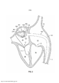
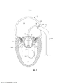
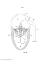
[00024] Figura 1 é uma vista em perspectiva de uma porção de um sistema de posicionamento de válvula mitral protética em uma vista em seção transversal de um coração humano nativo, de acordo com algumas modalidades.[00024] Figure 1 is a perspective view of a portion of a prosthetic mitral valve positioning system in a cross-sectional view of a native human heart, in accordance with some embodiments.
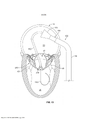
[00025] Figura 2 mostra uma vista em perspectiva de um conjunto de âncora de válvula mitral protética dentro do átrio esquerdo do coração após o conjunto de âncora ter emergido de uma bainha de aplicação de âncora do sistema de posicionamento da Figura 1.[00025] Figure 2 shows a perspective view of a prosthetic mitral valve anchor assembly within the left atrium of the heart after the anchor assembly has emerged from an anchor delivery sheath of the positioning system of Figure 1.
[00026] Figura 3 mostra uma vista em perspectiva do conjunto de âncora da Figura 2 após ser girado dentro do átrio esquerdo de modo a orientar o conjunto de âncora geralmente perpendicular à válvula mitral nativa.[00026] Figure 3 shows a perspective view of the anchor assembly of Figure 2 after being rotated within the left atrium so as to orient the anchor assembly generally perpendicular to the native mitral valve.
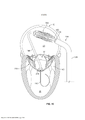
[00027] Figura 4 mostra uma vista em perspectiva do conjunto de âncora da Figura 3 após ser parcialmente avançado através da válvula mitral nativa de modo a posicionar projeções do conjunto de âncora abaixo de uma canaleta subanular da válvula mitral nativa.[00027] Figure 4 shows a perspective view of the anchor assembly of Figure 3 after being partially advanced through the native mitral valve in order to position projections of the anchor assembly below a subannular channel of the native mitral valve.
[00028] Figura 5 mostra uma vista em perspectiva do conjunto de âncora em uma disposição similar como mostrada na Figura 4, mas em uma vista em seção transversal comissural do coração (do lado esquerdo do coração).[00028] Figure 5 shows a perspective view of the anchor assembly in a similar arrangement as shown in Figure 4, but in a commissural cross-sectional view of the heart (on the left side of the heart).
[00029] Figura 6 mostra uma vista em perspectiva do conjunto de âncora da Figura 5 após ser retraído de modo a posicionar as projeções do conjunto de âncora dentro da canaleta subanular da válvula mitral nativa.[00029] Figure 6 shows a perspective view of the anchor assembly of Figure 5 after being retracted to position the projections of the anchor assembly within the subannular channel of the native mitral valve.
[00030] Figura 7 mostra uma vista em perspectiva do conjunto de âncora da Figura 6 após a retração de alguns membros do sistema de posicionamento.[00030] Figure 7 shows a perspective view of the anchor assembly of Figure 6 after retraction of some members of the positioning system.
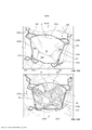
[00031] Figura 8 é uma vista de topo de uma válvula mitral nativa e apresenta um perímetro de canaleta da canaleta subanular da Figura 7 (sem o conjunto de âncora).[00031] Figure 8 is a top view of a native mitral valve and shows a channel perimeter of the subannular channel of Figure 7 (without the anchor assembly).
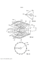
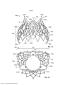
[00032] Figura 9 mostra uma vista em perspectiva de topo de um conjunto de âncora exemplar das Figuras 2-6 de acordo com algumas modalidades.[00032] Figure 9 shows a top perspective view of an exemplary anchor assembly of Figures 2-6 in accordance with some embodiments.
[00033] Figura 10 mostra uma vista em perspectiva do conjunto de âncora da Figura 9 com um material de cobertura disposto sobre porções da estrutura de âncora.[00033] Figure 10 shows a perspective view of the anchor assembly of Figure 9 with a covering material disposed over portions of the anchor structure.
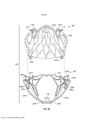
[00034] Figura 11A mostra uma vista em perspectiva de topo do conjunto de âncora da Figura 9 implantado dentro de uma válvula mitral nativa (com os folículos de válvula mitral nativa em um estado fechado), e Figura 11B mostra uma vista de topo anatômica correspondente do conjunto de âncora da Figura 11A.[00034] Figure 11A shows a top perspective view of the anchor assembly of Figure 9 implanted within a native mitral valve (with the native mitral valve follicles in a closed state), and Figure 11B shows a corresponding anatomical top view of the anchor assembly of Figure 11A.
[00035] Figura 12A mostra uma vista em perspectiva de topo do conjunto de âncora da Figura 9 implantado dentro da válvula mitral nativa da Figura 11A (com os folículos de válvula mitral nativa em um estado aberto), e Figura 12B mostra uma vista de topo anatômica correspondente do conjunto de âncora da Figura 12A.[00035] Figure 12A shows a top perspective view of the anchor assembly of Figure 9 implanted within the native mitral valve of Figure 11A (with the native mitral valve follicles in an open state), and Figure 12B shows a top view anatomy of the anchor set of Figure 12A.
[00036] Figura 13 mostra uma vista em perspectiva do conjunto de âncora da Figura 7 implantado dentro do válvula mitral nativa e uma bainha de aplicação de conjunto de válvula estendendo para dentro do átrio esquerdo.[00036] Figure 13 shows a perspective view of the anchor assembly of Figure 7 implanted within the native mitral valve and a valve assembly application sheath extending into the left atrium.
[00037] Figura 14 mostra uma vista em perspectiva de um conjunto de válvula dentro do átrio esquerdo após a emergência parcial da bainha de aplicação de conjunto de válvula da Figura 13. O conjunto de válvula está configurado em uma primeira disposição (parcialmente expandida).[00037] Figure 14 shows a perspective view of a valve assembly within the left atrium after partial emergence of the valve assembly application sheath of Figure 13. The valve assembly is configured in a first (partially expanded) arrangement.
[00038] Figura 15 mostra uma vista em perspectiva do conjunto de válvula da Figura 14 com o sistema de posicionamento de válvula sendo manipulado em preparação para a instalação do conjunto de válvula dentro do conjunto de âncora.[00038] Figure 15 shows a perspective view of the valve assembly of Figure 14 with the valve positioning system being manipulated in preparation for installing the valve assembly within the anchor assembly.
[00039] Figura 16 mostra uma vista em perspectiva do conjunto de válvula da Figura 15 (enquanto ainda na primeira disposição (parcialmente expandida)) sendo posicionado dentro do conjunto de âncora.[00039] Figure 16 shows a perspective view of the valve assembly of Figure 15 (while still in the first (partially expanded) arrangement) being positioned within the anchor assembly.
[00040] Figura 17 mostra uma vista em perspectiva do conjunto de válvula da Figura 16, o conjunto de válvula expandido dentro do conjunto de âncora e destacado do sistema de posicionamento.[00040] Figure 17 shows a perspective view of the valve assembly of Figure 16, the valve assembly expanded within the anchor assembly and detached from the positioning system.
[00041] Figura 18 mostra uma vista lateral anterior de uma estrutura de válvula de um conjunto de válvula da Figura 17, de acordo com algumas modalidades.[00041] Figure 18 shows a front side view of a valve structure of a valve assembly of Figure 17, in accordance with some embodiments.
[00042] Figura 19 mostra uma vista de fundo da estrutura de válvula da Figura 18.[00042] Figure 19 shows a bottom view of the valve structure of Figure 18.
[00043] Figura 20 é uma vista lateral posterior explodida de um conjunto de âncora e conjunto de válvula da Figura 17, de acordo com algumas modalidades.[00043] Figure 20 is an exploded rear side view of an anchor assembly and valve assembly of Figure 17, in accordance with some embodiments.
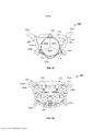
[00044] Figura 21 é uma vista de topo de um sistema de válvula mitral protética exemplar que inclui um conjunto de válvula acoplado com um conjunto de âncora, de acordo com algumas modalidades.[00044] Figure 21 is a top view of an exemplary prosthetic mitral valve system that includes a valve assembly coupled with an anchor assembly, in accordance with some embodiments.
[00045] Figura 22 é uma vista de fundo do sistema de válvula mitral protética exemplar da Figura 21.[00045] Figure 22 is a bottom view of the exemplary prosthetic mitral valve system of Figure 21.
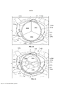
[00046] Figura 23 mostra uma vista de topo do sistema de válvula mitral protética da Figura 21 implantado dentro de uma válvula mitral nativa. A porção de oclusor do sistema de válvula mitral protética está mostrada em um estado fechado.[00046] Figure 23 shows a top view of the prosthetic mitral valve system of Figure 21 implanted within a native mitral valve. The occluder portion of the prosthetic mitral valve system is shown in a closed state.
[00047] Figura 24 mostra uma vista de topo do sistema de válvula mitral protética da Figura 21 implantado dentro de uma válvula mitral nativa. A porção de oclusor do sistema de válvula mitral protética está mostrada em um estado aberto.[00047] Figure 24 shows a top view of the prosthetic mitral valve system of Figure 21 implanted within a native mitral valve. The occluder portion of the prosthetic mitral valve system is shown in an open state.
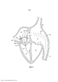
[00048] Figura 25 é uma vista de topo em seção transversal lateral de um coração que mostra as válvulas mitral, aórtica, tricúspide e pulmonar.[00048] Figure 25 is a lateral cross-sectional top view of a heart showing the mitral, aortic, tricuspid, and pulmonary valves.
[00049] Figura 26 é um diagrama esquemático de uma seção transversal de uma válvula mitral nativa que inclui o ânulo de válvula mitral.[00049] Figure 26 is a schematic diagram of a cross-section of a native mitral valve that includes the mitral valve annulus.
[00050] Figura 27 é uma vista lateral anterior de um conjunto de válvula, de acordo com algumas modalidades. Uma região de vedação do lado anterior do conjunto de válvula está demarcada sobre o conjunto de válvula.[00050] Figure 27 is a front side view of a valve assembly, in accordance with some embodiments. A sealing region on the front side of the valve assembly is marked over the valve assembly.
[00051] Figura 28 é uma vista lateral posterior de um conjunto de válvula, de acordo com algumas modalidades. Uma região de vedação do lado posterior do conjunto de válvula está demarcada sobre o conjunto de válvula.[00051] Figure 28 is a rear side view of a valve assembly, in accordance with some embodiments. A sealing region on the rear side of the valve assembly is marked over the valve assembly.
[00052] Figura 29 é uma vista lateral de um conjunto de válvula, de acordo com algumas modalidades. Uma região de vedação do lado lateral do conjunto de válvula está demarcada sobre o conjunto de válvula.[00052] Figure 29 is a side view of a valve assembly, according to some embodiments. A sealing region on the side of the valve assembly is marked on the valve assembly.
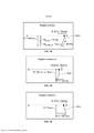
[00053] Figura 30 é uma apresentação esquemática de uma porção anterior de um conjunto de válvula em relação ao ânulo da válvula mitral nativa.[00053] Figure 30 is a schematic presentation of an anterior portion of a valve assembly in relation to the native mitral valve annulus.
[00054] Figura 31 é uma apresentação esquemática de uma porção de região comissural de um conjunto de válvula em relação ao ânulo da válvula mitral nativa.[00054] Figure 31 is a schematic presentation of a portion of the commissural region of a valve assembly in relation to the native mitral valve annulus.
[00055] Figura 32 é uma apresentação esquemática de uma porção posterior de um conjunto de válvula em relação ao ânulo da válvula mitral nativa.[00055] Figure 32 is a schematic presentation of a posterior portion of a valve assembly in relation to the native mitral valve annulus.
[00056] Figura 33 é uma vista em seção transversal do lado esquerdo de um coração que mostra um conjunto de válvula exemplar em relação ao ânulo da válvula mitral nativa e ao ânulo da raiz aórtica.[00056] Figure 33 is a cross-sectional view of the left side of a heart showing an exemplary valve assembly in relation to the native mitral valve annulus and aortic root annulus.
[00057] Figura 34 é uma imagem fluoroscópica de uma válvula mitral nativa com uma válvula protética exemplar na mesma, uma válvula aórtica, e um trato de efluxo ventricular esquerdo de um coração. A imagem também mostra o sangue fluindo do ventrículo esquerdo para a aorta através do trato de efluxo ventricular esquerdo.[00057] Figure 34 is a fluoroscopic image of a native mitral valve with an exemplary prosthetic valve in it, an aortic valve, and a left ventricular outflow tract of a heart. The image also shows blood flowing from the left ventricle into the aorta through the left ventricular outflow tract.
[00058] Figura 35 é outra imagem fluoroscópica de uma válvula mitral nativa com uma válvula protética exemplar na mesma, uma válvula aórtica, e um trato de efluxo ventricular esquerdo de um coração. A imagem também mostra o sangue fluindo do ventrículo esquerdo para a aorta através do trato de efluxo ventricular esquerdo.[00058] Figure 35 is another fluoroscopic image of a native mitral valve with an exemplary prosthetic valve in it, an aortic valve, and a left ventricular outflow tract of a heart. The image also shows blood flowing from the left ventricle into the aorta through the left ventricular outflow tract.
[00059] Figura 36 é uma apresentação esquemática do ânulo da válvula mitral nativa e do ânulo da raiz aórtica.[00059] Figure 36 is a schematic presentation of the native mitral valve annulus and aortic root annulus.
[00060] Figura 37 é uma vista em seção transversal comissural de um coração que mostra um conjunto de âncora de uma válvula mitral protética acoplada na canaleta subanular da válvula mitral nativa. Chordae tendineae no ventrículo esquerdo estão também apresentadas.[00060] Figure 37 is a commissural cross-sectional view of a heart showing an anchor assembly of a prosthetic mitral valve attached to the subannular groove of the native mitral valve. Chordae tendineae in the left ventricle are also shown.
[00061] Figura 38 é uma seção transversal lateral de um ventrículo esquerdo de um coração que mostra um conjunto de âncora de uma válvula mitral protética acoplado na canaleta subanular da válvula mitral nativa. Chordae tendineae no ventrículo esquerdo estão também apresentadas.[00061] Figure 38 is a lateral cross-section of a left ventricle of a heart showing a prosthetic mitral valve anchor assembly coupled to the subannular channel of the native mitral valve. Chordae tendineae in the left ventricle are also shown.
[00062] Figura 39 é uma vista em perspectiva de um conjunto de âncora que mostra fios de controle que são enfiados através de porções do conjunto de âncora.[00062] Figure 39 is a perspective view of an anchor assembly showing control wires being threaded through portions of the anchor assembly.
[00063] Figura 40 é outra vista em perspectiva de um conjunto de âncora que mostra fios de controle que são enfiados através de porções do conjunto de âncora.[00063] Figure 40 is another perspective view of an anchor assembly showing control wires being threaded through portions of the anchor assembly.
[00064] Figura 41 é uma vista lateral de uma estrutura de conjunto de válvula que mostra fios de controle que são enfiados através de porções da estrutura de conjunto de válvula.[00064] Figure 41 is a side view of a valve assembly structure showing control wires that are threaded through portions of the valve assembly structure.
[00065] Figura 42 é um diagrama esquemático de um padrão de enfiamento de um fio de controle mais próximo que corresponde à modalidade de estrutura de conjunto de válvula da Figura 41.[00065] Figure 42 is a schematic diagram of a closest control wire threading pattern that corresponds to the valve assembly structure embodiment of Figure 41.
[00066] Figura 43 é um diagrama esquemático de um padrão de enfiamento de um fio de controle de corpo médio que corresponde à modalidade de estrutura de conjunto de válvula da Figura 41.[00066] Figure 43 is a schematic diagram of a mid-body control wire threading pattern corresponding to the valve assembly structure embodiment of Figure 41.
[00067] Símbolos de referência iguais nos vários desenhos indicam elementos iguais.[00067] Equal reference symbols in the various drawings indicate equal elements.
[00068] Esta descrição descreve as modalidades de um sistema de válvula cardíaca protética, tal como sistemas de válvula mitral protética, e sistemas transcateter e métodos para implementar sistemas de válvula cardíaca protética. Em algumas modalidades, o sistema de válvula mitral protética pode ser posicionado para interfacear e ancorar em cooperação com as estruturas anatômicas nativas de uma válvula mitral (e, opcionalmente, em um modo que permita a função natural de chordae tendineae dos folículos de válvula mitral nativa mesmo após o componente de âncora ser posicionado). Como aqui descrito, o sistema de válvula mitral protética pode ser posicionado em um modo que interfaceia com as estruturas de válvula mitral nativa para criar uma vedação de fluido, por meio disto minimizando a MR e vazamentos paravalvulares após a implantação como abaixo descrito em mais detalhes, as Figuras 1-17 e 39-43 descrevem um sistema de aplicação de válvula mitral de transcateter e um método pelo qual o sistema de válvula mitral protética pode ser posicionado para interfacear e ancorar em cooperação com as estruturas anatômicas de uma válvula mitral nativa. Também, nas Figuras 18-32, características de válvula mitral protética estão descritas pelas quais as válvulas protéticas interfaceiam com as estruturas de válvula mitral nativa para criar uma vedação de fluido, por meio disto reduzindo a probabilidade de MR e vazamentos paravalvulares. Nas Figuras 33-36, as características e técnicas de válvula mitral protética estão descritas para gerenciar o fluxo sanguíneo através do trato de efluxo ventricular esquerdo (LVOT). Nas Figuras 37 38, as características e técnicas de válvula mitral protética estão descritas para reduzir o risco de interferência entre as válvulas protéticas e chordae tendineae.[00068] This description describes modalities of a prosthetic heart valve system, such as prosthetic mitral valve systems, and transcatheter systems and methods for implementing prosthetic heart valve systems. In some embodiments, the prosthetic mitral valve system may be positioned to interface and anchor in cooperation with the native anatomical structures of a mitral valve (and, optionally, in a manner that allows for the natural function of chordae tendineae of native mitral valve follicles even after the anchor component is positioned). As described herein, the prosthetic mitral valve system can be positioned in a manner that interfaces with native mitral valve structures to create a fluid seal, thereby minimizing MR and paravalvular leakage after implantation as described in more detail below. , Figures 1-17 and 39-43 describe a transcatheter mitral valve delivery system and a method by which the prosthetic mitral valve system can be positioned to interface and anchor in cooperation with the anatomical structures of a native mitral valve. Also, in Figures 18-32, prosthetic mitral valve features are depicted whereby prosthetic valves interface with native mitral valve structures to create a fluid seal, thereby reducing the likelihood of MR and paravalvular leaks. In Figures 33-36, prosthetic mitral valve features and techniques are described for managing blood flow through the left ventricular outflow tract (LVOT). In Figures 37-38, prosthetic mitral valve characteristics and techniques are described to reduce the risk of interference between the prosthetic valves and chordae tendineae.
[00069] Referindo à Figura 1, um sistema e método de aplicação de válvula mitral de transcateter exemplar 100 pode ser navegado através da vasculatura de um paciente para obter acesso ao coração do paciente 10. O sistema de aplicação de transcateter 100 facilita a implantação de uma válvula mitral protética em um coração que bate 10 utilizando uma técnica percutânea, de corte de vaso, ou minimamente invasiva (sem cirurgia de peito aberto). Em algumas implementações, o sistema de aplicação de transcateter 100 é utilizado em conjunto com uma ou mais modalidades de imagem tais como fluoroscopia de raios- x, ecocardiografia, imagem de ressonância magnética, tomografia computadorizada (CT), e similares.[00069] Referring to Figure 1, an exemplary transcatheter mitral valve delivery system and
[00070] O coração 10 (apresentado em seção transversal de uma perspectiva posterior) inclui um átrio direito 12, um ventrículo direito 14, um átrio esquerdo 16, e um ventrículo esquerdo 18. Uma válvula tricúspide 13 separa o átrio direito 12 do ventrículo direito 14. Uma válvula mitral 17 separa o átrio esquerdo 16 do ventrículo esquerdo 18. Um septo atrial 15 separa o átrio direito 12 do átrio esquerdo 16. Uma veia cava inferior 11 está confluente com o átrio direito 12. Deve ser compreendido que esta apresentação do coração 10 está um tanto estilizada. O mesmo é verdade para as Figuras 2-4. As Figuras 1-4 proveem apresentações gerais da proposta para a válvula mitral 17 que é utilizada em algumas implementações. Mas, as vistas em seção transversal comissural da Figura 5 e posteriores mais precisamente apresentam a orientação das válvulas mitrais protéticas em relação ao coração 10.[00070] Heart 10 (shown in cross-section from a posterior perspective) includes a
[00071] Na modalidade apresentada, o sistema de aplicação 100 inclui um fio de guia 110, um cateter flexionável primário 120, e uma bainha de aplicação de âncora 130. Componentes adicionais do sistema de aplicação 100 serão adicionalmente abaixo descritos. A bainha de aplicação de âncora 130 está deslizavelmente (e rotacionalmente) disposta dentro de um lúmen do cateter flexionável primário 120. O fio de guia 110 está disposto deslizável dentro de um lúmen da bainha de aplicação de âncora 130. Nesta apresentação a bainha de aplicação de âncora 130 foi parcialmente estendida em relação ao cateter flexionável primário 120, permitindo que uma porção alargada 132 expanda para fora, como adicionalmente abaixo descrito.[00071] In the presented embodiment, the
[00072] Na implementação apresentada, o fio de guia 110 é instalado dentro do coração 10 antes dos outros componentes do sistema de aplicação 100. Em algumas modalidades, o fio de guia 110 tem um diâmetro de aproximadamente 0,89 mm (aproximadamente 0,035 polegadas). Em algumas modalidades, o fio de guia 110 tem um diâmetro em uma faixa de aproximadamente 0,8 mm a aproximadamente 0,97 mm (aproximadamente 0,032 polegadas a aproximadamente 0,038 polegadas). Em algumas modalidades, o fio de guia 110 tem um diâmetro menor do que 0,80 mm (aproximadamente 0,032 polegadas) ou maior do que 0,97 mm (aproximadamente 0,038 polegadas). Em algumas modalidades, o fio de guia 110 é feito de materiais tais como, mas não limitados a, nitinol, aço inoxidável, aço inoxidável de alta resistência à tração, e similares, e suas combinações. O fio de guia 110 pode incluir vários projetos de ponta (por exemplo, ponta J, ponta reta, etc.), afinamentos, revestimentos, coberturas, marcadores radiopacos (RO), e outras características.[00072] In the implementation shown, the
[00073] Em algumas implementações, o fio de guia 110 é percutaneamente inserido em uma veia femoral do paciente. O fio de guia 110 é roteado para a veia cava inferior 11 e para dentro do átrio direito 12. Após criar uma abertura no septo atrial 15 (por exemplo, uma perfuração transseptal da fossa ovalis), o fio de guia 110 é roteado para dentro do átrio esquerdo 16. Finalmente, o fio de guia 110 é roteado através da válvula mitral 17 e para dentro do ventrículo esquerdo 18. Em algumas implementações, o fio de guia 110 pode ser instalado dentro do coração 10 ao longo de outros percursos anatômicos. O fio de guia 110 posteriormente serve como um trilho sobre o qual outros componentes do sistema de aplicação 100 são passados.[00073] In some implementations, the
[00074] Na implementação apresentada, o cateter flexionável primário 120 é instalado empurrando-o sobre o fio de guia 110. Em algumas implementações, uma ponta dilatadora é utilizada em conjunto com o cateter flexionável primário 120 conforme o cateter flexionável primário 120 é avançado sobre o fio de guia 110. Alternativamente, um cateter de balão poderia ser utilizado como o meio de dilatação inicial. Após a extremidade mais distante do cateter flexionável primário 120 alcançar o átrio esquerdo 16, a ponta dilatadora pode ser retirada. Em algumas modalidades, a porção de extremidade mais distante do cateter flexionável primário 120 é dirigível. Utilizando direcionamento, a porção de extremidade mais distante do cateter flexionável primário 120 pode ser orientada como desejado de modo a navegar a anatomia do paciente. Por exemplo, o cateter flexionável primário 120 pode ser inclinado dentro do átrio direito 12 para navegar o cateter flexionável primário 120 da veia cava inferior 11 para o septo atrial 15.[00074] In the implementation shown, the
[00075] Em algumas modalidades, o cateter flexionável primário 120 tem um diâmetro externo de aproximadamente 28 Fr (aproximadamente 9,3 mm). Em algumas modalidades, o cateter flexionável primário 120 tem um diâmetro externo na faixa de aproximadamente 26 Fr a aproximadamente 34 Fr (aproximadamente 8,7 mm a aproximadamente 11,3 mm). Em algumas modalidades, o cateter flexionável primário 120 tem um diâmetro externo na faixa de aproximadamente 20 Fr a aproximadamente 28 Fr (aproximadamente 6,7 mm a aproximadamente 9,3 mm).[00075] In some embodiments, the
[00076] O cateter flexionável primário 120 pode compreender um material polimérico ou metálico tubular. Por exemplo, em algumas modalidades o cateter flexionável primário 120 pode ser feito de materiais poliméricos, tais como, mas não limitados a, politetrafluoroetileno (PTFE), propileno etileno fluorado (FEP), HYTREL®, nylon, PICOFLEX®, PEBAX®, TECOFLEX®, e similares, e suas combinações. Em modalidades alternativas, o cateter flexionável primário 120 pode ser feito de materiais metálicos tais como, mas não limitados a, nitinol, aço inoxidável, ligas de aço inoxidável, titânio, ligas de titânio, e similares, e suas combinações. Em algumas modalidades, o cateter flexionável primário 120 pode ser feito de combinações de tais materiais poliméricos e metálicos (por exemplo, camadas de polímero com trança metálica, reforço de espiras, membros de enrijecimento, e similares, e suas combinações).[00076] The primary
[00077] O sistema de aplicação exemplar 100 também inclui a bainha de aplicação de âncora 130. Em algumas implementações, após o cateter flexionável primário 120 ser posicionado com sua extremidade mais distante dentro do átrio esquerdo 16, a bainha de aplicação de âncora 130 é instalada dentro de um lúmen do cateter flexionável primário 120 (sobre o fio de guia 110) e avançada através do cateter flexionável primário 120. Como adicionalmente abaixo descrito, em algumas modalidades a bainha de aplicação de âncora 130 é pré- carregada com um conjunto de âncora de válvula protética e outros componentes do sistema de aplicação 100.[00077] The
[00078] Em algumas modalidades, a bainha de aplicação de âncora 130 pode ser feita dos materiais acima descritos com referência ao cateter flexionável primário 120. Em algumas modalidades, a bainha de aplicação de âncora 130 tem um diâmetro externo na faixa de aproximadamente 20 Fr a aproximadamente 28 Fr (aproximadamente 6,7 mm a aproximadamente 9,3 mm). Em algumas modalidades, a bainha de aplicação de âncora 130 tem um diâmetro externo na faixa de aproximadamente 14 Fr a aproximadamente 24 Fr (aproximadamente 4,7 mm a aproximadamente 8,0 mm).[00078] In some embodiments, the anchoring
[00079] Na modalidade apresentada, a bainha de aplicação de âncora 130 inclui uma porção de extremidade mais distante alargada 132. Em algumas modalidades, nenhuma tal porção de extremidade mais distante alargada 132 está incluída. A porção de extremidade mais distante alargada 132 pode colapsar para um perfil mais baixo quando constrita dentro do cateter flexionável primário 120. Quando a porção de extremidade mais distante alargada 132 é expelida do cateter flexionável primário 120, a porção de extremidade mais distante alargada 132 pode autoexpandir para a forma alargada. Em algumas modalidades, o material da porção de extremidade mais distante alargada 132 inclui pregas ou dobras, pode ser uma extremidade alargada contínua ou pode ser separada em seções tais como pétalas de flor, e pode incluir um ou mais elementos resilientes que tensionam a porção de extremidade mais distante alargada 132 para assumir a configuração alargada na ausência de forças de restrição (tal como da contenção dentro do cateter flexionável primário 120). A porção de extremidade mais distante alargada 132 pode ser vantajosa, por exemplo, para recapturar o conjunto de âncora dentro do lúmen da bainha de aplicação de âncora 130 após o conjunto de âncora ter sido expelido porção de extremidade mais distante alargada 132.[00079] In the embodiment shown, the anchoring
[00080] Em algumas modalidades, o diâmetro externo máximo da porção de extremidade mais distante alargada 132 está em uma faixa de aproximadamente 30 Fr a aproximadamente 34 Fr (aproximadamente 10,0 mm a aproximadamente 11,3 mm). Em algumas modalidades, o diâmetro externo máximo da porção de extremidade mais distante alargada 132 está em uma faixa de aproximadamente 32 Fr a aproximadamente 44 Fr (aproximadamente 10,7 mm a aproximadamente 14,7 mm). Em algumas modalidades, o diâmetro externo máximo da porção de extremidade mais distante alargada 132 está em uma faixa de aproximadamente 24 Fr a aproximadamente 30 Fr (aproximadamente 8,0 mm a aproximadamente 10,0 mm). Em algumas modalidades, o diâmetro externo máximo da porção de extremidade mais distante alargada 132 é menor do que aproximadamente 24 Fr (aproximadamente 8,0 mm) ou maior do que aproximadamente 44 Fr (aproximadamente 14,7 mm).[00080] In some embodiments, the maximum outside diameter of the flared
[00081] Referindo à Figura 2, componentes adicionais do sistema de aplicação exemplar 100 podem incluir uma bainha de controle mais próxima 140, um cateter flexionável secundário 150, e um cateter empurrador mais distante 160. A bainha de controle mais próxima 140 está disposta deslizante dentro de um lúmen da bainha de aplicação de âncora 130. O cateter flexionável secundário 150 está disposto deslizante dentro de um lúmen da bainha de controle mais próxima 140. O cateter empurrador mais distante 160 está disposto deslizante dentro de um lúmen do cateter flexionável secundário 150. Estes componentes do sistema de aplicação 100 podem ser manipulados por um operador clínico para controlar a posição e orientação de um conjunto de âncora 200. O conjunto de âncora 200 está disposto deslizante sobre o fio de guia 110.[00081] Referring to Figure 2, additional components of the
[00082] Em algumas implementações do sistema de aplicação 100, uma ou mais da bainha de controle mais próxima 140, do cateter flexionável secundário 150, do cateter empurrador mais distante 160, e do conjunto de âncora 200 foram carregados dentro da bainha de aplicação de âncora 130 antes do avanço da bainha de aplicação de âncora 130 para dentro do cateter flexionável primário 120 como mostrado na Figura 1. Isto é, em alguns casos a bainha de controle mais próxima 140, o cateter flexionável secundário 150, o cateter empurrador mais distante 160, e/ou o conjunto de âncora 200 já estão instalados dentro da bainha de aplicação de âncora 130 conforme a bainha de aplicação de âncora 130 é avançada mais distante para dentro do cateter flexionável primário 120 para atingir a disposição mostrada na Figura 1. Em outras implementações, uma ou mais da bainha de controle mais próxima 140, do cateter flexionável secundário 150, do cateter empurrador mais distante 160, e do conjunto de âncora 200 são avançados mais distantes para dentro da bainha de aplicação de âncora 130 após a bainha de aplicação de âncora 130 ter sido avançada para dentro do cateter flexionável primário 120 para atingir a disposição mostrada na Figura 1.[00082] In some implementations of the
[00083] O cateter empurrador mais distante 160 está acoplado liberável com um cubo 210 do conjunto de âncora 200. Uma extremidade mais próxima do conjunto de âncora 200 está também acoplável liberável na bainha de controle mais próxima 140 por um ou mais fios de controle 142. Apesar da modalidade apresentada incluir um fio de controle 142, em algumas modalidades dois, três, quatro, cinco, ou mais do que cindo fios de controle estão incluídos.[00083] The
[00084] Referindo às Figuras 39 e 40, o fio de controle 142 está mostrado em um padrão de acoplamento exemplar com o conjunto de âncora 200. Na modalidade apresentada, o fio de controle 142 está enfiado através de uma pluralidade de porções mais próximas do conjunto de âncora 200. Na modalidade apresentada, o fio de controle 142 está configurado em uma disposição de laço. Consequentemente, um tensionamento do fio de controle 142 fará com que pelo menos a extremidade mais próxima do conjunto de âncora 200 contraia. Ao contrário, uma remoção de tensão do fio de controle 142 permitirá que o conjunto de âncora 200 expanda. Em algumas modalidades, o fio de controle 142 é enfiado através de olhais que estão dispostos sobre várias posições no conjunto de âncora 200. Em algumas modalidades, o fio de controle 142 está enfiado através de características de fixação que estão dispostas em várias posições sobre a cobertura ou estrutura do conjunto de âncora 200. O fio de controle 142 pode ser tensionado ou relaxado para chegar a uma extensão de expansão desejada da extremidade mais próxima do conjunto de âncora 200 (por exemplo, as características de retenção atrial 240a, 240b, 240c, e 240d, e/ou o anel supra-anular ondulante 250). Múltiplos fios de controle 142 poderiam também ser utilizados para conseguir uma expansão assimétrica, controlada do conjunto de âncora 200.[00084] Referring to Figures 39 and 40, the
[00085] Referindo novamente à Figura 2, a posição do conjunto de âncora 200 pode ser controlada manipulando as posições do cateter empurrador mais distante 160 e/ou da bainha de controle mais próxima 140. Por exemplo, na modalidade apresentada o conjunto de âncora 200 pode ser expelido para fora da bainha de aplicação de âncora 130 (como mostrado na Figura 2) movendo o cateter empurrador mais distante 160 e/ou a bainha de controle mais próxima 140 para mais distante em relação à bainha de aplicação de âncora 130. Em algumas implementações, o expulsão do conjunto de âncora 200 é causada puxando de volta para mais próximo a bainha de aplicação de âncora 130 enquanto geralmente mantendo as posições do cateter empurrador mais distante 160 e/ou da bainha de controle mais próxima 140. Em algumas implementações, a expulsão do conjunto de âncora 200 é causada por uma combinação de puxar de volta para mais próximo a bainha de aplicação de âncora 130 enquanto estendendo para mais distante as posições do cateter empurrador mais distante 160 e/ou da bainha de controle mais próxima 140.[00085] Referring again to Figure 2, the position of the
[00086] Como o conjunto de âncora 200 emerge dos confins da bainha de aplicação de âncora 130, o conjunto de âncora 200 expande de uma configuração de aplicação de baixo perfil para uma configuração parcialmente expandida (como mostrado na Figura 2). A extensão de expansão do conjunto de âncora 200 pode ser pelo menos parcialmente controlada pelo posicionamento relativo da bainha de controle mais próxima 140 em relação ao cateter empurrador mais distante 160. Por exemplo, conforme a bainha de controle mais próxima 140 é movida para mais próximo em relação ao cateter empurrador mais distante 160, o conjunto de âncora 200 é axialmente alongado e radialmente contraído. Ao contrário, conforme a bainha de controle mais próxima 140 é movida para mais distante em relação ao cateter empurrador mais distante 160, o conjunto de âncora 200 é axialmente encurtado e radialmente expandido. Em algumas implementações, este controle do tamanho radial do conjunto de âncora é utilizado por um clínico durante o processo de posicionar o conjunto de âncora 200 dentro da válvula mitral nativa 17, como adicionalmente abaixo descrito. Como adicionalmente abaixo descrito, o fio de controle 142 pode também ser utilizado para controlar alguma expansão radial do conjunto de âncora 300 (sem mudar a distância relativa da bainha de controle mais próxima 140 em relação ao cateter empurrador mais distante 160).[00086] As the
[00087] Deve ser compreendido que as válvulas mitrais protéticas aqui providas são compreendidas de um conjunto de âncora 200 e um conjunto de válvula separável (por exemplo, referir às Figuras 14-20). O conjunto de âncora 200 é posicionado para uma disposição que interfaceia dentro do válvula mitral nativa 17 antes do posicionamento do conjunto de válvula. Dito diferentemente, após implantar o conjunto de âncora 200 dentro da válvula mitral nativa 17, o conjunto de válvula pode então ser posicionado dentro do conjunto de âncora 200 e dentro do válvula mitral nativa 17 (como adicionalmente abaixo descrito). Portanto, pode ser dito que as válvulas mitrais protéticas aqui providas são posicionadas utilizando um método de implantação em estágios. Isto é, o conjunto de âncora 200 é posicionado em um estágio, e o conjunto de válvula é posicionado em um estágio subsequente. Em algumas implementações, o posicionamento do conjunto de válvula acontece logo após o posicionamento do conjunto de âncora 200 (por exemplo, durante o mesmo procedimento médico). Em algumas implementações, o posicionamento do conjunto de válvula acontece horas, dias, semanas, ou mesmo meses após o posicionamento do conjunto de âncora 200 (por exemplo, durante um procedimento médico subsequente).[00087] It should be understood that the prosthetic mitral valves provided herein are comprised of an
[00088] O método de implantação em estágios das válvulas mitrais protéticas aqui providas é facilitado pelo fato que quando o próprio conjunto de âncora 200 é implantado dentro do válvula mitral nativa 17, a válvula mitral nativa 17 continua a funcionar essencialmente como antes da implantação do conjunto de âncora 200 sem um impacto significativo sobre a fisiologia cardiovascular. Este é o caso porque, como adicionalmente abaixo descrito, o conjunto de âncora 200 interfaceia e ancora dentro de aspectos estruturais da válvula mitral nativa 17 sem substancialmente interferir com os folículos ou chordae tendineae da válvula mitral nativa 17.[00088] The method of staged implantation of the prosthetic mitral valves provided herein is facilitated by the fact that when the
[00089] Ainda referindo à Figura 2, na disposição apresentada a porção de extremidade mais distante do cateter flexionável secundário 150 está localizado pelo menos parcialmente internamente dentro do conjunto de âncora 200. O cateter flexionável secundário 150 pode ser manipulado por um operador clínico para reversivelmente dobrar a porção de extremidade mais distante do cateter flexionável secundário 150. Conforme o cateter flexionável secundário 150 é dobrado pelo clínico, outros componentes do sistema de aplicação 100 podem dobrar juntamente com o cateter flexionável secundário 150. Por exemplo, um ou mais do empurrador mais distante 160 e da bainha de controle mais próxima 140 podem dobrar em resposta ao dobramento do cateter flexionável 150. Como o conjunto de âncora 200 está acoplado no empurrador mais distante 160 e na bainha de controle mais próxima 140, o conjunto de âncora 200 pode, por sua vez, ser girado dobrando o cateter flexionável secundário 150.[00089] Still referring to Figure 2, in the arrangement shown the distal end portion of the secondary
[00090] Referindo à Figura 3, como acima descrito, o cateter flexionável secundário 150 pode ser articulado (também referido como dirigido, defletido, dobrado, curvado, etc.) para articular lateralmente (girar, rodar, etc.) o conjunto de âncora 200 enquanto o conjunto de âncora 200 está dentro do átrio esquerdo 16. Tal rotação do conjunto de âncora 200 é vantajosa, por exemplo, para orientar o conjunto de âncora 200 em uma relação desejada com a válvula mitral nativa 17 em preparação para implantar o conjunto de âncora 200 dentro do válvula mitral nativa 17. Em algumas implementações, é desejável orientar o conjunto de âncora 200 de modo que o seu eixo geométrico longitudinal fique geralmente perpendicular à válvula mitral nativa 17. A articulação lateral do conjunto de âncora 200 parcialmente ou totalmente expandido dentro do átrio 16 pode ser vantajoso versus precisar articular lateralmente o conjunto de âncora 200 enquanto este está ainda constrito dentro da bainha de aplicação, já que o último conjunto é um conjunto de cateter relativamente grande e rígido.[00090] Referring to Figure 3, as described above, the secondary
[00091] Na preparação para acoplar o conjunto de âncora 200 com a válvula mitral nativa 17, o operador clínico pode manipular o tamanho radial da estrutura de âncora 200 de modo que a estrutura de âncora 200 possa ser passada através válvula mitral nativa 17 sem danificar a válvula mitral nativa 17. Por exemplo, o clínico pode mover a bainha de controle mais próxima 140 para mais próximo em relação ao cateter empurrador mais distante 160 para radialmente contrair o conjunto de âncora 200. Com o conjunto de âncora 200 radialmente contraído, a estrutura de âncora 200 pode ser seguramente passada através da válvula mitral nativa 17 sem danificar a válvula mitral nativa 17.[00091] In preparation for coupling the
[00092] Referindo à Figura 4, enquanto o cateter flexionável secundário 150 está retido na sua configuração como descrito com referência à Figura 3, o cateter empurrador mais distante 160 e a bainha de controle mais próxima 140 podem ser simultaneamente avançados. Como o cateter empurrador mais distante 160 está acoplado liberável no cubo 210 do conjunto de âncora 200, e como a bainha de controle mais próxima 140 está acoplada liberável na extremidade mais próxima do conjunto de âncora 200 através dos um ou mais fios 142a e 142b, um avanço simultâneo do cateter empurrador mais distante 160 e da bainha de controle mais próxima 140 resulta no avanço do conjunto de âncora 200. O conjunto de âncora 200 é avançado de modo que a extremidade mais distante do conjunto de âncora 200 fique dentro do ventrículo esquerdo 18 enquanto a extremidade mais próxima do conjunto de âncora 200 fique dentro do átrio esquerdo 16. Com isto, algumas porções do conjunto de âncora 200 estão em cada lado da válvula mitral nativa 17.[00092] Referring to Figure 4, while the secondary
[00093] Na modalidade apresentada, o conjunto de âncora 200 inclui quatro pés de âncora: um pé anterior esquerdo 220a, um pé posterior esquerdo 220b, um pé posterior direito 220c, e um pé anterior direito 220d. Em algumas modalidades, menos ou mais pés de âncora podem estar incluídos (por exemplo, dois, três, cinco, seis, ou mais do que seis). Em algumas modalidades, os pés de âncora 220a, 220b, 220c, e 220d são porções do conjunto de âncora 200 que estão configuradas para contato com a canaleta subanular 19 da válvula mitral nativa 17, sem penetrar no tecido da válvula mitral nativa 17. Consequentemente, os pés de âncora 220a, 220b, 220c, e 220d têm superfícies atraumáticas que são geralmente comparáveis a pés. No entanto, em algumas modalidades um ou mais dos pés de âncora 220a, 220b, 220c, e 220d estão configurados para penetrar no tecido e podem ter características de âncora tais como farpas, espiras, ganchos, e similares.[00093] In the embodiment shown, the
[00094] Na disposição da Figura 4, os pés de âncora 220a, 220b, 220c, e 220d estão posicionados abaixo da canaleta subanular 19. Nesta disposição, o tamanho radial do conjunto de âncora 200 pode ser aumentado para alinhar os pés de âncora 220a, 220b, 220c, e 220d com a canaleta subanular 19. Por exemplo, o clínico pode mover a bainha de controle mais próxima 140 para mais distante em relação ao cateter empurrador mais distante 160 para radialmente expandir o conjunto de âncora 200 para alinhar os pés de âncora 220a, 220b, 220c, e 220d com a canaleta subanular 19. Tal alinhamento pode ser executado em preparação para assentar os pés de âncora 220a, 220b, 220c, e 220d dentro do canaleta subanular 19.[00094] In the arrangement of Figure 4, the
[00095] Referindo à Figura 5, uma vista em seção transversal comissural do coração 10 provê outra perspective do conjunto de âncora 200 na mesma disposição em relação à válvula mitral nativa 17 como mostrado na Figura 4. Esta vista em seção transversal comissural do coração 10 é uma vista em seção transversal feita através da válvula mitral 17 ao longo de um plane através do átrio esquerdo 16 e ventrículo esquerdo 18 que é paralela à linha que intersecta as duas comissuras da válvula mitral 17 (como descrito ainda abaixo com referência à Figura 8). Nas seguintes Figuras 5-7 e 13-17, a vista em seção transversal comissural do coração 10 será utilizada para descrever o sistema de aplicação 100 e métodos para posicionar as válvulas mitrais protéticas aqui providas. A vista nas Figuras 5-7 e 13-17 está ligeiramente inclinada de modo que uma melhor visualização do conjunto de âncora 200 seja provida.[00095] Referring to Figure 5, a commissural cross-sectional view of the
[00096] Os pés de âncora 220a, 220b, 220c, e 220d estão posicionados abaixo da canaleta subanular 19. Nesta posição, os pés de âncora 220a, 220b, 220c, e 220d estão posicionados sob as excursões sistólica e diastólica dos folículos da válvula mitral nativa 17. Nesta orientação, os pés de âncora 220a, 220b, 220c, e 220d podem estar alinhados com a canaleta subanular 19 em preparação para assentar os pés de âncora 220a, 220b, 220c, e 220d dentro do canaleta subanular 19.[00096]
[00097] Referindo à Figura 6, o empurrador mais distante 160 e a bainha de controle mais próxima 140 podem ser simultaneamente retraídos em relação ao cateter flexionável secundário 150 e ao cateter flexionável primário 120. Como um resultado, os pés de âncora 220a, 220b, 220c, e 220d tornam-se assentados dentro da canaleta subanular 19. Nesta posição, os pés de âncora 220a, 220b, 220c, e 220d estão posicionados sob as excursões sistólica e diastólica dos folículos da válvula mitral nativa 17, e as outras estruturas do conjunto de âncora 200 não inibem os movimentos do folículos. Portanto, com o conjunto de âncora 200 acoplado nas estruturas da válvula mitral 17 como descrito, a válvula mitral 17 pode continuar a funcionar como fazia antes da colocação do conjunto de âncora 200. Além disso, o modo no qual o conjunto de âncora 200 interfaceia com a válvula mitral nativa 17 não resulta em deformação da válvula mitral nativa 17. Portanto, a válvula mitral nativa 17 pode continuar a funcionar como fazia antes da colocação do conjunto de âncora 200.[00097] Referring to Figure 6, the
[00098] Referindo à Figura 7, com o conjunto de âncora 200 acoplado dentro da válvula mitral nativa 17, os componentes do sistema de aplicação 100 podem ser retirados do conjunto de âncora 200. Por exemplo, o fio de controle 142 pode ser destacado da extremidade mais próxima do conjunto de âncora 200. Posteriormente, a bainha de controle mais próxima 140 pode ser retirada. O cateter flexionável secundário 150 pode também ser retirado. De fato, se assim desejado, a bainha de controle mais próxima 140, o cateter flexionável secundário 150, e a bainha de aplicação de âncora 130 podem ser completamente retirados do cateter flexionável primário 120. Em contraste, em algumas implementações o cateter empurrador mais distante 160 é vantajosamente deixado preso no cubo 210 do conjunto de âncora 200. Como será ainda abaixo descrito, em algumas implementações o cateter empurrador mais distante 160 pode ser utilizado como um trilho sobre o qual um conjunto de válvula é posicionados no interior do conjunto de âncora 200. No entanto, em algumas implementações o conjunto de âncora 200 é completamente destacado do sistema de aplicação 100, e o sistema de aplicação 100 é removido do paciente. Após um período de horas, dias, semanas, ou meses, subsequente ao posicionamento do conjunto de âncora 200, um conjunto de válvula pode ser instalado dentro do conjunto de âncora 200 para completar a instalação da válvula mitral protética.[00098] Referring to Figure 7, with the
[00099] Referindo às Figuras 8 e 9, a anatomia da válvula mitral nativa 17 inclui algumas características estruturais consistentes e previsíveis através de pacientes que podem ser utilizadas para acoplar o conjunto de âncora 200 nesta. Por exemplo, a válvula mitral nativa 17 inclui a acima mencionada canaleta subanular 19. Além disso, a válvula mitral nativa 17 inclui um ânulo em forma de D 28, uma comissura anterolateral 30a, uma comissura posteromedial 30b, um trígono fibroso esquerdo 134a, e a trígono fibroso direito 134b. Ainda, a válvula mitral nativa 17 inclui um folículo anterior 20 e um folículo posterior em três partes 22. O folículo posterior 22 inclui uma concha lateral 24a, uma concha do meio 24b, e uma concha medial 24c. As bordas livres do folículo posterior 22 e do folículo anterior 20 encontram-se ao longo de uma linha de coaptação 32.[00099] Referring to Figures 8 and 9, the anatomy of the native
[000100] O ânulo em forma de D 28 define a estrutura da qual o folículo anterior 20 e o folículo posterior 22 estendem e articulam. Os trígonos fibrosos esquerdo e direito 134a e 134b estão localizados próximos das extremidades esquerda e direita do folículo anterior 20 e geralmente adjacentes às concha lateral e medial 24a e 24c do folículo posterior 22. A canaleta subanular 19 corre ao longo do ânulo 28 entre os trígonos fibroso esquerdo e direito 134a e 134b ao longo do folículo posterior 22.[000100] The D-shaped
[000101] As regiões nos ou próximas dos trígonos anulares de alto colágeno 134a e 134b podem geralmente ser confiáveis para prover localizações de ancoragem fortes, estáveis. O tecido muscular nas regiões nos ou próximas dos trígonos 134a e 134b também provê um bom substrato de encravamento de tecido para estabilidade e resistência de migração adicionais do conjunto de âncora 200. Portanto, as regiões nos ou próximas dos trígonos 134a e 134b definem uma zona de âncora anterior esquerda 34a e uma zona de âncora anterior direita 34b respectivamente. A zona de âncora anterior esquerda 34a e a zona de âncora anterior direita 34b proveem localizações alvo vantajosas para a colocação do pé anterior esquerdo 220a e do pé anterior direito 220d respectivamente.[000101] The regions at or near the high collagen
[000102] A modalidade apresentada do conjunto de âncora 200 também inclui o pé posterior esquerdo 220b e o pé posterior direito 220c. Como anteriormente descrito, o pé posterior esquerdo 220b e o pé posterior direito 220c podem também ser vantajosamente posicionados dentro da canaleta subanular 19 de modo a prover um acoplamento balanceado e atraumático do conjunto de âncora 200 na válvula mitral nativa 17. Portanto, uma zona de âncora posterior esquerda 34b e uma zona de âncora anterior direita 34c são definidas na canaleta subanular 19. A zona de âncora posterior esquerda 34b e a zona de âncora anterior direita 34c podem receber o pé posterior esquerdo 220b e o pé posterior direito 220c respectivamente. Em algumas implementações, as localizações da zona de âncora posterior esquerda 34b e da zona de âncora anterior direita 34c podem varias das localizações apresentadas enquanto ainda permanecendo dentro do canaleta subanular 19. Deve ser compreendido que o conjunto de âncora 200 apresentado é meramente um exemplo não limitante dos conjuntos de âncora providos dentro do escopo desta descrição.[000102] The shown embodiment of the
[000103] Em algumas modalidades, o conjunto de âncora 200 inclui estruturas supra-anulares e estruturas subanulares. Por exemplo, as estruturas subanulares do conjunto de âncora 200 incluem os acima mencionados pés de âncora 220a, 220b, 220c, e 220d, e o cubo 210. Em algumas modalidades, como acima descrito, o cubo 210 funciona como uma estrutura de conexão para o sistema de aplicação 100 (por exemplo, referir à Figura 2). Além disso, o cubo 210 pode funcionar como um componente estrutural estabilizante do qual um braço de suporte subanular anterior esquerdo 230a, um braço de suporte subanular posterior esquerdo 230b, um braço de suporte subanular posterior direito 230c, e um braço de suporte subanular anterior direito 230d estendem para o pés de âncora 220a, 220b, 220c, e 220d respectivamente.[000103] In some embodiments, the
[000104] Em algumas modalidades, tal como a modalidade apresentada, as estruturas supra-anulares do conjunto de âncora 200 incluem: uma característica de retenção atrial anterior esquerda 240a, uma característica de retenção atrial posterior esquerda 240b, uma característica de retenção atrial posterior direita 240c, e uma característica de retenção atrial anterior direita 240d; um arco de âncora anterior 250a, um arco de âncora esquerdo 250b, um arco de âncora posterior 250c, e um arco de âncora direito 250d; e pontes de conexão 260. O arco de âncora anterior 250a, o arco de âncora esquerdo 250b, o arco de âncora posterior 250c, e o arco de âncora direito 250d estão unidos uns com os outros para formar um anel supra-anular ondulante 250 que atua como um elemento estrutural supra-anular para o conjunto de âncora 200. Como será ainda abaixo descrito, o anel supra-anular 250 também define uma abertura para um espaço no interior do conjunto de âncora 200 que está configurado para receber e acoplar com um conjunto de válvula. As características de retenção atrial 240a, 240b, 240c, e 240d estão configuradas para contactar a superfície de tecido supra-anular como prateleira acima do ânulo de válvula mitral, e para por meio disto estabilizar o conjunto de âncora 200 em áreas supra-anulares que estão geralmente opostas aos pés de âncora 220a, 220b, 220c, e 220d respectivamente.[000104] In some embodiments, such as the one shown, the supra-annular structures of the
[000105] Em algumas modalidades, pontes de conexão 260 proveem uma estabilidade e resistência à fadiga melhoradas de forças verticalmente orientadas sobre um conjunto de válvula artificial companheira quando a válvula (não mostrada) está fechada e bloqueando o sangue pressurizado durante a sístole. O conjunto de âncora 200 pode também incluir um ou mais furos 226 em porções de estruturas adjacentes aos pés, os quais são pontos de controle adicionais para aplicação e recuperação do conjunto, ou poderiam ser utilizados para prender uma estrutura de aplicação posicional.[000105] In some embodiments, connecting
[000106] Em algumas modalidades, tal como a modalidade apresentada, as estruturas supra-anulares e estruturas subanulares do conjunto de âncora 200 estão interconectadas por uma conexão interanular anterior lateral 270a, uma conexão interanular posterior lateral 270b, a conexão interanular posterior medial 270c, e a conexão interanular anterior medial 270d. Por exemplo, a conexão interanular anterior lateral 270a conecta o pé de âncora anterior lateral 220a com a característica de retenção atrial anterior lateral 240a. Além disso, a conexão interanular anterior lateral 270a conecta o pé de âncora anterior lateral 220a com o arco de âncora anterior 250a e o arco de âncora esquerdo 250b. Na modalidade apresentada, cada uma das outras conexões interanulares 270b, 270c, e 270d interconectam as porções da estruturas supra-anulares e das estruturas subanulares em modos análogos àquele da conexão interanular anterior lateral 270a. Por exemplo, a conexão interanular anterior lateral 270b conecta o pé de âncora anterior lateral 220b com o arco de âncora esquerdo 250b e o arco de âncora posterior 250c; a conexão interanular anterior lateral 270c conecta o pé de âncora anterior lateral 220c com o arco de âncora posterior 250c e o arco de âncora direito 250d; e a conexão interanular anterior lateral 270d conecta o pé de âncora anterior lateral 220d com o arco de âncora direito 250d e o arco de âncora anterior 250a.[000106] In some embodiments, such as the embodiment shown, the supra-annular structures and sub-annular structures of the
[000107] Em algumas modalidades, os membros alongados do conjunto de âncora 200 estão formados de uma única peça de precursor material (por exemplo, chapa ou tubo) que é cortado, expandido, e conectado no cubo 210. Por exemplo, algumas modalidades são fabricadas de um tubo que é cortado a laser (ou usinado, quimicamente gravado, cortado com jato de água, etc.) e então expandido e ajustado por calor no seu tamanho e forma expandido final. Em algumas modalidades, o conjunto de âncora 200 é criado compostamente de múltiplos membros alongados (por exemplo, fios ou membros cortados) que são unidos juntos com o cubo 210 e uns com os outros para formar o conjunto de âncora 200.[000107] In some embodiments, the elongate members of the
[000108] Os membros alongados do conjunto de âncora 200 podem ser compreendidos de vários materiais e combinações de materiais. Em algumas modalidades, o nitinol (NiTi) é utilizado como o material dos membros alongados do conjunto de âncora 200, mas outros materiais tais como aço inoxidável, aço L605, polímeros, aço MP35N, aços inoxidáveis, titânio, liga de cobalto / cromo, materiais poliméricos, Pyhnox, Elgiloy, ou qualquer outro material biocompatível apropriado e suas combinações podem ser utilizados. As propriedades superelásticas de NiTi o tornam um material candidato especificamente bom para os membros alongados do conjunto de âncora 200 porque, por exemplo, o NiTi pode ser ajustado por calor em uma forma desejada. Isto é, o NiTi pode ser ajustado por calor de modo que o conjunto de âncora 200 tenda a autoexpandir em uma forma desejada quando o conjunto de âncora 200 não está constrito, tal como quando o conjunto de âncora 200 é posicionado para fora da bainha de aplicação de âncora 130. Um conjunto de âncora 200 feito de NiTi, por exemplo, pode ter uma natureza de mola que permite o conjunto de âncora 200 ser elasticamente colapsado ou "esmagado" para uma configuração de aplicação de baixo perfil e então reconfigurar para a configuração expandida como mostrado na Figura 9. O conjunto de âncora 200 pode ser geralmente conformável, resistente à fadiga, e elástico de modo que o conjunto de âncora 200 possa conformar com a topografia do tecido circundante quando o conjunto de âncora 200 é posicionado dentro de uma válvula mitral nativa de um paciente.[000108] The elongate members of the
[000109] Em algumas modalidades, o diâmetro ou largura / espessura de um ou mais dos membros alongados que formam o conjunto de âncora 200 pode estar dentro de uma faixa de aproximadamente 0,20 mm a aproximadamente 0,40 mm (aproximadamente 0,008" a aproximadamente 0,015") , ou aproximadamente 0,23 mm a aproximadamente 0,76 mm (aproximadamente 0,009" a aproximadamente 0,030") , ou aproximadamente 0,25 mm a aproximadamente 1,52 mm (aproximadamente 0,01" a aproximadamente 0,06"), ou aproximadamente 0,51 mm a aproximadamente 2,54 mm (aproximadamente 0,02" a aproximadamente 0,10"), ou aproximadamente 1,52 mm a aproximadamente 5,08 mm (aproximadamente 0,06" a aproximadamente 0,20"). Em algumas modalidades, os membros alongados que formam o conjunto de âncora 200 podem ter diâmetros ou larguras / espessuras menores ou maiores. Em algumas modalidades, cada um dos membros alongados que formam o conjunto de âncora 200 tem essencialmente o mesmo diâmetro ou largura / espessura. Em algumas modalidades, um ou mais dos membros alongados que formam o conjunto de âncora 200 têm um diferente diâmetro ou largura / espessura do que um ou mais dos outros membros alongados do conjunto de âncora 200. Em algumas modalidades, uma ou mais porções de um ou mais dos membros alongados que formam o conjunto de âncora 200 podem ser afinados, alargados, estreitados, curvos, em raio, ondulados, espiralados, inclinados, e/ou de outro modo não lineares e/ou não consistente ao longo do comprimento inteiro dos membros alongados do conjunto de âncora 200. Tais características e técnicas podem também ser incorporadas com os conjuntos de válvula das válvulas mitrais protéticas aqui providas.[000109] In some embodiments, the diameter or width/thickness of one or more of the elongate members forming the
[000110] Em algumas modalidades, os membros alongados que formam o conjunto de âncora 200 podem variar em diâmetro, espessura e/ou largura de modo a facilitar variações nas forças que são exercidas pelo conjunto de âncora 200 em suas regiões específicas, para aumentar ou diminuir a flexibilidade do conjunto de âncora 200 em certas regiões, para melhorar a resistência de migração, e/ou para controlar o processo de compressão (esmagamento) na preparação para o posicionamento e o processo de expansão durante posicionamento do conjunto de âncora 200.[000110] In some embodiments, the elongated members that form the
[000111] Em algumas modalidades, um ou mais dos membros alongados que formam o conjunto de âncora 200 podem ter uma seção transversal circular. Em algumas modalidades, um ou mais dos membros alongados que formam o conjunto de âncora 200 podem ter uma forma de seção transversal retangular, ou outra forma de seção transversal que não é retangular. Exemplos de formas de seção transversal que os membros alongados que formam o conjunto de âncora 200 podem ter incluem circular, em forma de C, quadrada, ovular, retangular, elíptica, triangular, em forma de D, trapezoidal, incluindo formas de seção transversal irregulares formadas por uma construção trançada ou de fios, e similares. Em algumas modalidades, um ou mais dos membros alongados que formam o conjunto de âncora 200 podem ser essencialmente planos (isto é, de modo que a razão de largura para espessura seja aproximadamente 2:1, aproximadamente 3:1, aproximadamente 4:1, aproximadamente 5:1, ou maior do que aproximadamente 5:1). Em alguns exemplos, um ou mais dos membros alongados que formam o conjunto de âncora 200 podem ser formados utilizando uma técnica de esmerilhamento sem centro, de modo que o diâmetro dos membros alongados varie ao longo do comprimento dos membros alongados.[000111] In some embodiments, one or more of the elongate members forming the
[000112] O conjunto de âncora 200 pode incluir características que estão direcionadas para melhorar uma ou mais características de desempenho funcional desejáveis dos dispositivos de válvula mitral protética. Por exemplo, algumas características do conjunto de âncora 200 podem ser direcionadas para melhorar a conformabilidade dos dispositivos válvula mitral protética. Tais características podem facilitar um desempenho aperfeiçoado dos dispositivos de válvula mitral protética permitindo os dispositivos conformarem a topografias de tecido irregulares e/ou topografias de tecido dinamicamente variáveis, por exemplo. Tais características de conformabilidade podem ser vantajosas para prover um desempenho efetivo e durável dos dispositivos de válvula mitral protética. Em algumas modalidades do conjunto de âncora 200, algumas porções do conjunto de âncora 200 estão projetadas para serem mais conformáveis do que outras porções do mesmo conjunto de âncora 200. Isto é, a conformabilidade de um único conjunto de âncora 200 pode ser projetada para ser diferente em várias áreas do conjunto de âncora 200.[000112]
[000113] Em algumas modalidades, o conjunto de âncora 200 inclui características para visibilidade radiográfica in vivo melhorada. Em algumas modalidades, porções do conjunto de âncora 200, tal como um ou mais dos pés de âncora 220a, 220b, 220c, e 220d, podem ter um ou mais marcadores radiopacos presos a estes. Em algumas modalidades, algumas ou todas as porções do conjunto de âncora 200 estão revestidas (por exemplo, revestidas por crepitação) com um revestimento radiopaco.[000113] In some embodiments, the
[000114] Ainda referindo às Figuras 8 e 9, como acima descrito os pés de âncora 220a, 220b, 220c, e 220d estão dimensionados e formados para acoplar a canaleta subanular 19 da válvula mitral 17. Em algumas modalidades, os pés anteriores 220a e 220d estão espaçados um do outro por uma distância na faixa de aproximadamente 30 mm a aproximadamente 45 mm, ou aproximadamente 20 mm a aproximadamente 35 mm, ou aproximadamente 40 mm a aproximadamente 55 mm. Em algumas modalidades, Os pés posterior 220b e 220c estão espaçados um do outro por uma distância em uma faixa de aproximadamente 20 mm a aproximadamente 30 mm, ou aproximadamente 10 mm a aproximadamente 25 mm, ou aproximadamente 25 mm a aproximadamente 40 mm.[000114] Still referring to Figures 8 and 9, as described above, the
[000115] Em algumas modalidades, os pés de âncora 220a, 220b, 220c, e 220d têm uma altura que varia de aproximadamente 8 mm a aproximadamente 12 mm, ou mais do que aproximadamente 12 mm. Em algumas modalidades, os pés de âncora 220a, 220b, 220c, e 220d tem uma área de superfície de acoplamento de canaleta (quando cobertos com tecido) que varia de aproximadamente 6 mm2 a aproximadamente 24 mm2. Em algumas modalidades, os pés de âncora 220a, 220b, 220c, e 220d cada um tem essencialmente a mesma área de superfície de acoplamento de canaleta. Em modalidades específicas, um ou mais dos pés de âncora 220a, 220b, 220c, e 220d têm uma diferente área de superfície de acoplamento de canaleta do que um ou mais dos outros pés de âncora 220a, 220b, 220c, e 220d. Os pés de âncora 220a, 220b, 220c, e 220d podem ter larguras que variam dentro de aproximadamente 1,5 mm a aproximadamente 4,0 mm ou mais, e comprimentos que variam dentro de aproximadamente 3 mm a aproximadamente 6 mm ou mais. Os pés de âncora 220a, 220b, 220c, e 220d estão dimensionados e formados de modo que o conjunto de âncora 200 não significativamente prejudique a função natural chordae tendineae de válvula mitral, dos folículos de válvula mitral nativa, e músculos papilares mesmo após o conjunto de âncora se ancorado no local de válvula mitral.[000115] In some embodiments, the
[000116] Como anteriormente descrito, o conjunto de âncora 200 está projetado para evitar interferência com o funcionamento da válvula mitral nativa 17. Portanto, o conjunto de âncora 200 pode implantado dentro da válvula mitral nativa 17 algum tempo antes do posicionamento neste de um conjunto de válvula substituição, sem degradação da função da válvula 17 durante o período de tempo entre a implantação de âncora e a implantação de válvula (sendo este tempo na ordem de minutos, ou mesmo diversos dias ou meses). Para evitar tal interferência entre o conjunto de âncora 200 e a válvula mitral nativa 17, as conexões interanulares 270a, 270b, 270c, e 270d passam através da linha de coaptação 32 aproximadamente. Mais especificamente, a conexão interanular anterior esquerda 270a passa através da linha de coaptação 32 adjacente à comissura anterolateral 30a. Em modo semelhante, a conexão interanular anterior direita 270d passa através da linha de coaptação 32 adjacente à comissura posteromedial 30b. Em algumas implementações, a conexão interanular posterior esquerda 270b e a conexão interanular posterior direita 270c passam através da válvula mitral nativa 17 em localizações que são posteriormente tensionadas da linha de coaptação natural 32. O folículo posterior 22 tenderá a conformadamente enrolar ao redor conexão interanular posterior esquerda 270b e da conexão interanular posterior direita 270c para facilitar a vedação da válvula mitral 17, com o conjunto de âncora 200 acoplado a esta.[000116] As previously described, the
[000117] Em referência à Figura 10, em algumas modalidades o conjunto de âncora 200 inclui um material de cobertura 270 disposto sobre uma ou mais porções do conjunto de âncora 200. O material de cobertura 270 pode prover vários benefícios. Por exemplo, em algumas implementações o material de cobertura 270 pode facilitar o encravamento de tecido e/ou endotelialização, por meio disto melhorando a resistência à migração do conjunto de âncora 200 e impedindo a formação de trombos sobre elementos de contato de sangue. Em outro exemplo, como adicionalmente abaixo descrito, o material de cobertura 270 pode ser utilizado para facilitar o acoplamento entre o conjunto de âncora 200 e um conjunto de válvula que é recebido no mesmo. O material de cobertura 270 também impede ou minimiza a abrasão e/ou atrito entre o conjunto de âncora 200 e o conjunto de válvula 300. O material de cobertura 270 também impede válvula um desgaste relativo à abrasão de tecido externo de válvula.[000117] Referring to Figure 10, in some embodiments the
[000118] Na modalidade apresentada, o material de cobertura 270 está disposto essencialmente sobre o conjunto de âncora inteiro 200. Em algumas modalidades, o material de cobertura 270 está disposto sobre uma ou mais porções do conjunto de âncora 200, enquanto uma ou mais outras porções do conjunto de âncora 200 não têm o material de cobertura 270 disposto nestas. Apesar da modalidade apresentada incluir o material de cobertura 270, o material de cobertura 270 não é requerido em todas as modalidades. Em algumas modalidades, duas ou mais porções de material de cobertura 270, as quais podem ser separadas e/ou distintas umas das outras, podem estar dispostas sobre o conjunto de âncora 200. Isto é, em algumas modalidades um tipo específico de material de cobertura 270 está disposto sobre algumas áreas do conjunto de âncora 200 e um diferente tipo de material de cobertura 270 está disposto sobre outras áreas do conjunto de âncora 200.[000118] In the embodiment shown, the covering
[000119] Em algumas modalidades, o material de cobertura 270, ou suas porções, compreende um fluoropolímero, tal como um polímero de politetrafluoroetileno expandido (ePTFE). Em algumas modalidades, o material de cobertura 270, ou suas porções, compreende um poliéster, um silicone, um uretano, ELAST-EON™ (um polímero de silicone e uretano), outro polímero biocompatível, DACRON®, tereftalato de polietileno (PET), copolímeros, ou suas combinações e subcombinações. Em algumas modalidades, o material de cobertura 270 é fabricado utilizando técnicas tais como, mas não limitadas a, extrusão, expansão, tratamento térmico, sinterização, malharia, trançado, tecido, tratamento químico, e similares.[000119] In some embodiments, the
[000120] Em algumas modalidades, o material de cobertura 270, ou suas porções, compreende um tecido biológico. Por exemplo, em algumas modalidades o material de cobertura 270 pode incluir tecidos naturais tais como, mas não limitados a, pericárdio bovino, suíno, ovino, ou equino. Em algumas tais modalidades, os tecidos são quimicamente tratados utilizando soluções de glutaraldeído, formaldeído, ou triglicidilamina (TGA), ou outros agentes de ligação cruzada de tecido adequados.[000120] In some embodiments, the covering
[000121] Na modalidade apresentada, o material de cobertura 270 está disposto no interior e no exterior do conjunto de âncora 200. Em algumas modalidades, o material de cobertura 270 está disposto sobre apenas o exterior do conjunto de âncora 200. Em algumas modalidades, o material de cobertura 270 está disposto sobre apenas o interior do conjunto de âncora 200. Em algumas modalidades, algumas porções do conjunto de âncora 200 são cobertas pelo material de cobertura 270 em um modo diferente do que outras porções do conjunto de âncora 200.[000121] In the embodiment shown, the covering
[000122] Em algumas modalidades, o material de cobertura 270 está preso a pelo menos algumas porções do conjunto de âncora 200 utilizando um adesivo. Em algumas modalidades, FEP (etileno propileno fluorado) é utilizado como um adesivo para prender o material de cobertura 270 no conjunto de âncora 200, ou suas porções. Por exemplo, um revestimento de FEP pode ser aplicado a algumas ou todas as porções do conjunto de âncora 200, e o FEP pode atuar como um agente de ligação para aderir o material de cobertura 270 no conjunto de âncora 200. Em algumas modalidades, enrolamento, costura, atadura, bandagem, e/ou clipes, e similares podem ser utilizados para prender o material de cobertura 270 no conjunto de âncora 200. Em algumas modalidades, uma combinação de técnicas é utilizada para prender o material de cobertura 270 no conjunto de âncora 200.[000122] In some embodiments, the
[000123] Em algumas modalidades, o material de cobertura 270, ou suas porções, tem uma estrutura microporosa que provê uma plataforma de encravamento de tecido para vedação durável e/ou força de ancoragem suplementar do conjunto de âncora 200. Em algumas modalidades, o material de cobertura 270 é feita de um material membranoso que inibe ou reduz a passagem de sangue através do material de cobertura 270. Em algumas modalidades, o material de cobertura 270, ou suas porções, tem uma composição de material e/ou configuração que inibe ou impede o encravamento de tecido e/ou endotelialização no material de cobertura 270.[000123] In some embodiments, the
[000124] Em algumas modalidades, o material de cobertura 270 pode ser modificado por um ou mais processos químicos ou físicos que melhoram certas propriedades físicas do material de cobertura 270. Por exemplo, um revestimento hidrofílico pode ser aplicado no material de cobertura 270 para aperfeiçoar a molhabilidade e translucidez de eco do material de cobertura 270. Em algumas modalidades, o material de cobertura 270 pode ser modificado com metades químicas que promovem ou inibem uma ou mais de fixação de célula endotelial, migração de célula endotelial, proliferação de célula endotelial, e resistência à trombose. Em algumas modalidades, o material de cobertura 270 pode ser modificado com heparina covalentemente anexada ou impregnado com uma ou mais substâncias de droga que são liberadas in situ.[000124] In some embodiments, the
[000125] Em algumas modalidades, o material de cobertura 270 é pré- perfurado para modular o fluxo de fluido através do material de cobertura 270 e/ou afetar a propensão para encravamento de tecido no material de cobertura 270. Em algumas modalidades, o material de cobertura 270 é tratado para tornar o material de cobertura 270 mais rígido ou para adicionar uma textura de superfície. Por exemplo, em algumas modalidades o material de cobertura 270 é tratado com pó de FEP para prover um material de cobertura enrijecido 270 ou superfície áspera sobre o material de cobertura 270. Em algumas modalidades, porções selecionadas do material de cobertura 270 são assim tratadas, enquanto outras porções do material de cobertura 270 não são assim tratadas. Outras técnicas de tratamento de material de material de cobertura 270 podem também ser empregadas para propriedades mecânicas benéficas e interações de resposta de tecido. Em algumas modalidades, porções do material de cobertura 270 têm um ou mais marcadores radiopacos presos a estas para melhorar a visualização radiográfica in vivo.[000125] In some embodiments, the
[000126] Referindo agora às Figuras 11A e 12A, o conjunto de âncora 200 está mostrado implantado dentro de uma válvula mitral nativa 17. As Figuras 11B e 12B são fotografias que correspondem As Figuras 11A e 12A respectivamente. Na Figura 11A, a válvula mitral 17 está mostrada em um estado fechado. Na Figura 12A, a válvula mitral 17 está mostrada em um estado aberto. Estas ilustrações são da perspectiva do átrio esquerdo olhando na direção da válvula mitral 17. Por exemplo, na Figura 12A as chordae tendineae 40 são visíveis através dos folículos abertos da válvula mitral 17.[000126] Referring now to Figures 11A and 12A, the
[000127] Estas figuras ilustram as estruturas supra-anulares e estruturas subanulares do conjunto de âncora 200 e suas relações com a válvula mitral nativa 17. Por exemplo, o estado fechado da válvula mitral nativa 17 na Figura 11A permite a visibilidade das estruturas supra-anulares tal com a característica de retenção atrial anterior esquerda 240a, a característica de retenção atrial posterior esquerda 240b, a característica de retenção atrial posterior direita 240c, e a característica de retenção atrial anterior direita 240d. Além disso, o arco de âncora anterior 250a, o arco de âncora esquerdo 250b, o arco de âncora posterior 250c, o arco de âncora direito 250d, e as pontes de conexão 260 são visíveis. No entanto, as estruturas subanulares não são visíveis in Figura 11A porque tais estruturas estão obstruídas da vista pelo folículo anterior 20 e o folículo posterior em três partes 24a, 24b, e 24c.[000127] These figures illustrate the supra-annular structures and sub-annular structures of the
[000128] Em contraste, na Figura 12A certas estruturas subanulares do conjunto de âncora 200 são visíveis porque a válvula mitral nativa 17 está aberta. Por exemplo, os braços de suporte subanulares 230a, 230b, 230c, e 230d e o cubo 210 estão em vista através da válvula mitral aberta 17. Apesar de tudo, os pés de âncora 220a, 220b, 220c, e 220d permanecem fora de vista devido à sua localização dentro da canaleta subanular da válvula mitral 17.[000128] In contrast, in Figure 12A certain subannular structures of the
[000129] Referindo à Figura 13, após a implantação do conjunto de âncora 200 dentro da válvula mitral nativa 17 (como executada, por exemplo, de acordo com as Figuras 1-7 acima descritas), uma bainha de aplicação de válvula 170 do sistema de aplicação 100 pode ser utilizada para posicionar um conjunto de válvula dentro do conjunto de âncora 200. Como acima descrito com referência à Figura 7, com o cateter empurrador mais distante 160 acoplado com o cubo 210 do conjunto de âncora 200, o cateter empurrador mais distante 160 pode ser utilizado para guiar o conjunto de válvula para o interior do conjunto de âncora 200.[000129] Referring to Figure 13, after implantation of the
[000130] Em algumas implementações, com o cateter flexionável primário 120 posicionado com a sua extremidade mais distante dentro do átrio esquerdo 16, a bainha de aplicação de válvula 170 está instalada dentro de um lúmen do cateter flexionável primário 120 (sobre o cateter empurrador mais distante 160) e avançada através do cateter flexionável primário 120. Como adicionalmente abaixo descrito, em algumas modalidades a bainha de aplicação de válvula 170 é pré- carregada com um conjunto de válvula e outros componentes do sistema de aplicação 100. O cateter flexionável primário 120 pode ser o mesmo cateter que foi utilizado para aplicar o conjunto de âncora 200, ou pode ser um diferente cateter (mais ainda aqui referido como o cateter flexionável primário 120 para o bem da simplicidade).[000130] In some implementations, with the primary
[000131] Em algumas modalidades, a bainha de aplicação de válvula 170 pode ser feita dos materiais acima descritos com referência ao cateter flexionável primário 120. Em algumas modalidades, a bainha de aplicação de válvula 170 tem um diâmetro externo na faixa de aproximadamente 20 Fr a aproximadamente 28 Fr (aproximadamente 6,7 mm a aproximadamente 9,3 mm). Em algumas modalidades, a bainha de aplicação de válvula 170 tem um diâmetro externo na faixa de aproximadamente 14 Fr a aproximadamente 24 Fr (aproximadamente 4,7 mm a aproximadamente 8,0 mm).[000131] In some embodiments, the
[000132] Na modalidade apresentada, a bainha de aplicação de válvula 170 inclui uma porção de extremidade mais distante alargada 172. Em algumas modalidades, nenhuma tal porção de extremidade mais distante alargada 172 está incluída. A porção de extremidade mais distante alargada 172 pode colapsar para um perfil mais baixo quando constrita dentro do cateter flexionável primário 120. Quando a porção de extremidade mais distante alargada 172 é expelida do cateter flexionável primário 120, a porção de extremidade mais distante alargada 172 pode autoexpandir para a forma alargada. Em algumas modalidades, o material da porção de extremidade mais distante alargada 172 inclui pregas ou dobras, pode ser uma extremidade alargada contínua ou pode ser separada em seções, tais como pétalas de flor, e pode um ou mais elementos resilientes que tensionam a porção de extremidade mais distante alargada 172 para assumir a configuração alargada na ausência de forças de restrição (tal como da contenção dentro do cateter flexionável primário 120). A porção de extremidade mais distante alargada 172 pode ser vantajosa, por exemplo, para recapturar o conjunto de válvula dentro do lúmen da bainha de aplicação de válvula 170 após o conjunto de válvula ter sido expelido da porção de extremidade mais distante alargada 172.[000132] In the embodiment shown, the
[000133] Em algumas modalidades, o diâmetro externo máximo da porção de extremidade mais distante alargada 172 está em uma faixa de aproximadamente 30 Fr a aproximadamente 34 Fr (aproximadamente 10,0 mm a aproximadamente 11,3 mm). Em algumas modalidades, o diâmetro externo máximo da porção de extremidade mais distante alargada 172 está em uma faixa de aproximadamente 32 Fr a aproximadamente 44 Fr (aproximadamente 10,7 mm a aproximadamente 14,7 mm). Em algumas modalidades, o diâmetro externo máximo da porção de extremidade mais distante alargada 172 está em uma faixa de aproximadamente 24 Fr a aproximadamente 30 Fr (aproximadamente 8,0 mm a aproximadamente 10,0 mm). Em algumas modalidades, o diâmetro externo máximo da porção de extremidade mais distante alargada 172 é menor do que aproximadamente 24 Fr (aproximadamente 8,0 mm) ou maior do que aproximadamente 44 Fr (aproximadamente 14,7 mm).[000133] In some embodiments, the maximum outside diameter of the flared furthest end portion 172 is in a range of approximately 30 Fr to approximately 34 Fr (approximately 10.0 mm to approximately 11.3 mm). In some embodiments, the maximum outside diameter of the flared furthest end portion 172 is in a range of approximately 32 Fr to approximately 44 Fr (approximately 10.7 mm to approximately 14.7 mm). In some embodiments, the maximum outside diameter of the flared furthest end portion 172 is in a range of approximately 24 Fr to approximately 30 Fr (approximately 8.0 mm to approximately 10.0 mm). In some embodiments, the maximum outside diameter of the flared distal end portion 172 is less than approximately 24 Fr (approximately 8.0 mm) or greater than approximately 44 Fr (approximately 14.7 mm).
[000134] Referindo à Figura 14, em algumas implementações a bainha de aplicação de válvula 170 pode ser recuada para dentro do cateter flexionável primário 120 enquanto um cateter de aplicação de válvula 180 é mantido substancialmente estacionário para expelir um conjunto de válvula 300 de um lúmen da bainha de aplicação de válvula 170. A bainha de aplicação de válvula 170 e o cateter de aplicação de válvula 180 são componentes adicionais em algumas modalidades do sistema de aplicação exemplar 100.[000134] Referring to Figure 14, in some implementations the
[000135] O conjunto de válvula 300 pode ser acoplado liberável no cateter de aplicação de válvula 180 e retido em uma configuração de baixo perfil. Em algumas modalidades, ambas as extremidade mais distante e mais próximas do conjunto de válvula 300 estão acopladas liberáveis no cateter de aplicação de válvula 180. Em algumas modalidades, apenas uma da extremidade mais distante ou da extremidade mais próxima do conjunto de válvula 300 está acoplada liberável no cateter de aplicação de válvula 180. Em modalidades específicas, um ou mais fios de controle podem estar incluídos para acoplar liberável uma ou mais porções do conjunto de válvula 300 no cateter de aplicação de válvula 180.[000135]
[000136] Referindo às Figuras 41-43, o conjunto de válvula 300 está acoplado liberável no cateter de aplicação de válvula 180 através de um fio de controle mais próximo 342a e um fio de controle de meio corpo 342b. Os fios de controle 342a e 342b são enfiados através de um ou mais lúmens dentro do cateter de aplicação de válvula 180. Os fios de controle 342a e 342b saem do cateter de aplicação de válvula 180 e passam através de olhais sobre as porções de extremidade mais próxima e meio corpo do conjunto de válvula 300 respectivamente. Os fios de controle 342a e 342b são então enfiados de volta dentro do cateter de aplicação de válvula 180. Manipulando os fios de controle 342a e 342b, um operador clínico pode controlar o conjunto de válvula 300. Por exemplo, a expansão e contração do conjunto de válvula 300 podem ser controladas, e o destacamento do conjunto de válvula 300 do cateter de aplicação de válvula pode ser controlado, manipulando a tensão e posição do fios de controle 342a e 342b dentro do cateter de aplicação 180.[000136] Referring to Figures 41-43, the
[000137] Referindo novamente à Figura 14, um lúmen do cateter de aplicação de válvula 180 pode circundar deslizante o cateter empurrador mais distante 160. Portanto, o avanço do cateter de aplicação de válvula 180 resulta no avanço do conjunto de válvula 300 sobre o cateter empurrador mais distante 160 na direção do conjunto de âncora 200.[000137] Referring again to Figure 14, a lumen of the
[000138] Referindo às Figuras 15 e 16, o sistema de aplicação 100 pode ser manipulado por um operador clínico para executar uma articulação lateral (giro, rotação, etc.) do conjunto de válvula 300 dentro do átrio esquerdo 16. A rotação do conjunto de válvula 300 muda o alinhamento do conjunto de válvula 300 de ser geralmente axial com a porção de extremidade mais distante do cateter flexionável primário 120 para ser geralmente axial com o conjunto de âncora 200 (em preparação para instalação do conjunto de válvula 300 no interior do conjunto de âncora 200).[000138] Referring to Figures 15 and 16, the
[000139] Em algumas implementações, a acima mencionada rotação do conjunto de válvula 300 pode ser executada como segue. Como mostrado na Figura 15, devido à influência do cateter flexionável primário 120 sobre o cateter de aplicação de válvula 180, o eixo geométrico do conjunto de válvula 300 está inicialmente em alinhamento geral com o eixo geométrico da porção de extremidade mais distante do cateter flexionável primário 120. Desta disposição, um simultâneo contra movimento entre o cateter empurrador mais distante 160 e o cateter de aplicação de válvula 180 pode ser executado pelo clínico para girar o conjunto de válvula 300. Isto é, conforme o cateter empurrador mais distante 160 é puxado para mais próximo, o cateter de aplicação de válvula 180 é empurrado para mais distante. Como um resultado deste contra movimento, o conjunto de válvula 300 gira em um raio relativamente apertado, como requerido pelos confins do átrio esquerdo 16. Posteriormente, o cateter de aplicação de válvula 180 pode ser avançado adicionalmente de modo que o conjunto de válvula 300 fique coaxialmente posicionado no interior do conjunto de âncora 200 como mostrado na Figura 16.[000139] In some implementations, the aforementioned rotation of
[000140] Referindo agora também à Figura 17, em algumas modalidades o conjunto de válvula 300 e o conjunto de âncora 200 tornam-se alinhados um com o outro coaxialmente, linearmente (ao longo de seus eixos), e rotacionalmente antes da ou durante a expansão do conjunto de válvula 300, resultando no acoplamento entre o conjunto de válvula 300 e o conjunto de âncora 200. Posteriormente, o sistema de aplicação 100 pode ser retirado do coração 10 e a válvula mitral protética pode executar a sua função.[000140] Referring now also to Figure 17, in some embodiments the
[000141] O alinhamento coaxial entre o conjunto de válvula 300 e o conjunto de âncora 200, como acima descrito, é conseguido em virtude do cateter de aplicação de válvula 180 ser disposto deslizante sobre o cateter empurrador mais distante 160. O alinhamento linear entre o conjunto de válvula 300 e o conjunto de âncora 200 pode ser conseguido pela interação de uma característica de extremidade mais distante 182 do cateter de aplicação de válvula 180 e o cubo 210 do conjunto de âncora 200. Por exemplo, em algumas modalidades um topamento da característica de extremidade mais distante 182 e do cubo 210 pode resultar em um alinhamento linear apropriado entre o conjunto de válvula 300 e o conjunto de âncora 200.[000141] Coaxial alignment between the
[000142] O alinhamento rotacional relativo entre o conjunto de válvula 300 e o conjunto de âncora 200 (ao redor seus eixos) pode ser conseguido em vários modos. Por exemplo, em algumas modalidades o cateter de aplicação de válvula 180 está mecanicamente chavetado no cateter empurrador mais distante 160 para fixar deslizante um alinhamento rotacional desejado entre o conjunto de válvula 300 e o conjunto de âncora 200. Em algumas modalidades, outros tipos de características mecânicas (por exemplo, pinos / furos, protrusões / receptáculos, etc.) podem ser incluídas para facilitar um alinhamento rotacional / de giro desejado entre o conjunto de válvula 300 e o conjunto de âncora 200. Alternativamente, ou além disso, marcadores radiopacos podem estar incluídos sobre o conjunto de válvula 300 e sobre o conjunto de âncora 200 em localizações e/ou padrões que são indicativos da orientação rotacional relativa (ao redor de seus eixos) do conjunto de válvula 300 e do conjunto de âncora 200. Em algumas modalidades, (por exemplo, quando o cateter de aplicação de válvula 180 "torqueável") o cateter de aplicação de válvula 180 pode ser girado ao redor de seu eixo geométrico até que os marcadores estejam em posição apropriada em relação ao conjunto de âncora 200, antes da expansão final do conjunto de válvula 300. Fluoroscopia pode ser utilizada para atingir uma orientação relativa desejada dos marcadores radiopacos, e do conjunto de válvula 300 e o conjunto de âncora 200 correspondentemente.[000142] Relative rotational alignment between the
[000143] Referindo às Figuras 18 e 19, um conjunto de válvula exemplar 300 está mostrado sem nenhuma cobertura ou folículos de válvula / oclusor. Com isto, uma estrutura de conjunto de válvula 301 do conjunto de válvula 300 está mostrada. A Figura 18 mostra uma vista lateral anterior da estrutura de conjunto de válvula 301, e a Figura 19 mostra uma vista de fundo da estrutura de conjunto de válvula 301. O conjunto de válvula 300 pode ser construído utilizando qualquer um dos vários materiais e técnicas de fabricação acima descritos com referência à estrutura de âncora 200 (por exemplo, referir à Figura 9). Deve ser compreendido que o conjunto de válvula 300 apresentado é meramente um exemplo não limitante dos conjuntos de válvula providos dentro do escopo desta descrição.[000143] Referring to Figures 18 and 19, an
[000144] O conjunto de válvula 300 inclui uma porção de extremidade mais próxima 302 e uma porção de extremidade mais distante 304. O conjunto de válvula inclui uma porção de saia externa alargada 303 que define uma porção de orifício interno 305. Quando o conjunto de válvula 300 é implantado em uma válvula mitral nativa, a porção de extremidade mais próxima 302 está localizada supra-anular (dentro do átrio esquerdo) e a porção de extremidade mais distante 304 está localizada subanular (dentro do ventrículo esquerdo). A porção de extremidade mais próxima 302 define o orifício de entrada geralmente circular do conjunto de válvula 300, como adicionalmente abaixo descrito.[000144] The
[000145] Na modalidade apresentada, o conjunto de válvula 300 geralmente alarga para fora ao longo de uma direção mais distante. Dito diferentemente, a porção de extremidade mais distante 304 está alargada para fora em comparação com a porção de extremidade mais próxima 302. Consequentemente, a porção de extremidade mais próxima 302 define um menor perfil externo em comparação com a porção de extremidade mais distante 304. No entanto, algumas regiões da porção de extremidade mais distante 304 arqueiam para dentro. Especificamente, por exemplo, um canto comissural posteromedial 330a e um canto comissural anterolateral 330b do conjunto de válvula 300 podem arquear para dentro. Deve ser compreendido que o alargamento para fora da porção de extremidade mais distante 304 em comparação com a porção de extremidade mais próxima 302 é meramente uma configuração exemplar para um perfil do conjunto de válvula 300. Em algumas modalidades, por exemplo, um ressalto (uma porção do conjunto de válvula 300 que tem a maior periferia externa) está localizado próximo do meio do conjunto de válvula 300.[000145] In the embodiment shown, the
[000146] O conjunto de válvula 300 também inclui um lado anterior 306 entre o canto comissural posteromedial 330a e o canto comissural anterolateral 330b. Quando o conjunto de válvula 300 é implantado em uma válvula mitral nativa, o lado anterior 306 faceia o folículo anterior da válvula mitral nativa. O lado anterior 306 da porção de extremidade mais distante 304 define uma superfície geralmente plana, enquanto que os outros lados da porção de extremidade mais distante 304 são arredondados. Com isto, a periferia da porção de extremidade mais distante 304 é geralmente em forma de D. A periferia em forma de D da porção de extremidade mais distante 304 provê o conjunto de válvula 300 com um vantajoso perfil externo para interfacear e vedar com a válvula mitral nativa. Como adicionalmente abaixo descrito, a vedação é obtida pela coaptação entre a periferia em forma de D da porção de extremidade mais distante 304 e os folículos da válvula mitral nativa, e, em algumas modalidades, entre a periferia em forma de D na região da saia 303 com o ânulo de válvula nativa.[000146] The
[000147] Na modalidade apresentada, a porção de extremidade mais próxima 302 do conjunto de válvula 300 inclui três arcos de folículo atriais 310a, 310b, e 310c que juntamente definem um anel ondulante na porção de extremidade mais próxima 302. Cada um dos arcos de folículo 310a, 310b, e 310c inclui um vértice que tem um furo de fixação 312a, 312b, e 312c respectivamente. Em algumas modalidades, os furos de fixação 312a, 312b, e 312c são utilizados para acoplar a extremidade mais próxima do conjunto de válvula 300 a um cateter de aplicação (por exemplo, cateter de aplicação de válvula 180 das Figuras 14-16).[000147] In the embodiment shown, the
[000148] O conjunto de válvula 300 também inclui três postes comissurais 320a, 320b, e 320c que cada um estendem mais distante das interseções dos três arcos de folículo 310a, 310b, e 310c. Os postes comissurais 320a, 320b, e 320c estão dispostos a aproximadamente 120° afastados uns dos outros. Os postes comissurais 320a, 320b, e 320c cada um tem uma série de furos que podem ser utilizados para fixação de folículos, tal como por sutura. Os três arcos de folículo 310a, 310b, e 310c e os três postes comissurais 320a, 320b, e 320c são áreas sobre o conjunto de válvula 300 nas quais três folículos de válvula protética tornam-se presos para compreender um oclusor de tri-folículo (por exemplo, referir as Figuras 22-25).[000148] The
[000149] Como melhor visto na Figura 19, os três arcos de folículo 310a, 310b, e 310c e os postes comissurais 320a, 320b, e 320c definem uma estrutura geralmente cilíndrica para a construção de oclusor de tri- folículo. Como tal, o conjunto de válvula 300 provê uma configuração de estrutura provada e vantajosa para o oclusor de tri-folículo. O oclusor de tri-folículo provê um fluxo aberto durante a diástole e oclusão de fluxo durante a sístole.[000149] As best seen in Figure 19, the three
[000150] Referindo à Figura 20, uma apresentação explodida de uma válvula protética exemplar mitral 400 inclui um conjunto de âncora 200 e um conjunto de válvula 300. Estas figuras proveem uma vista lateral posterior do conjunto de âncora 200 e do conjunto de válvula 300.[000150] Referring to Figure 20, an exploded view of an exemplary prosthetic
[000151] O conjunto de válvula 300 inclui uma cobertura 340. A cobertura 340 pode ser feita de qualquer um dos materiais e construída utilizando qualquer uma das técnicas acima descritas em referência à cobertura 270. Além disso, em algumas modalidades a cobertura 340 pode compreender tecidos naturais tais como, mas não limitados a, pericárdio bovino, suíno, ovino, ou equino. Em algumas tais modalidades, os tecidos são quimicamente ligados cruzados utilizando uma solução de glutaraldeído, formaldeído, ou triglicidilamina ou outros agentes de ligação cruzada adequados.[000151] The
[000152] Quando o conjunto de válvula 300 e o conjunto de âncora 200 estão acoplados juntos, o conjunto de válvula 300 está geometricamente intertravado no interior do conjunto de âncora 200 (por exemplo, em algumas modalidades em virtude da forma afinada do conjunto de válvula 300 dentro do anel supra-anular e espaço interno do conjunto de âncora 200). Especificamente, em algumas modalidades o conjunto de válvula 300 está contido dentro do espaço interno entre o anel supra-anular 250 e os braços de suporte subanulares 230a, 230b, 230c, e 230d. Como acima descrito, a disposição intertravada entre o conjunto de válvula 300 e o conjunto de âncora 200 é conseguida posicionando um conjunto de válvula 300 em uma configuração de baixo perfil no interior do conjunto de âncora 200 e então permitindo a expansão do conjunto de válvula 300 no interior do conjunto de âncora 200 (por exemplo, referir às Figuras 16 e 17).[000152] When the
[000153] Referindo às Figuras 21 e 22, uma configuração posicionada da válvula protética exemplar mitral 400 inclui o conjunto de válvula 300 acoplado com o conjunto de âncora 200. A Figura 21 mostra uma vista de topo (atrial) da válvula mitral protética 400, e a Figura 22 mostra uma vista de fundo (ventrículo) da válvula mitral protética 400.[000153] Referring to Figures 21 and 22, a positioned configuration of exemplary prosthetic
[000154] Em algumas modalidades, tal como a modalidade apresentada, conjunto de válvula 300 inclui três folículos 350a, 350b, e 350c que executam a função de oclusão da válvula mitral protética 400. Os cúspide dos três folículos 350a, 350b, e 350c estão fixos nos três arcos de folículo atrial 310a, 310b, e 310c, e nos três postes comissurais 320a, 320b, e 320c (referir às Figuras 18 e 19). As bordas livres dos três folículos 350a, 350b, e 350c podem vedar por coaptação uns com os outros durante a sístole e abrir durante a diástole.[000154] In some embodiments, such as the embodiment shown,
[000155] Os três folículos 350a, 350b, e 350c podem ser compreendidos de materiais naturais ou sintéticos. Por exemplo, os três folículos 350a, 350b, e 350c podem ser compreendidos de qualquer dos materiais acima descritos com referência à cobertura 340, incluindo os tecidos naturais tais como, mas não limitados a, pericárdio bovino, suíno, ovino, ou equino. Em algumas tais modalidades, os tecidos são quimicamente ligados cruzados utilizando uma solução de glutaraldeído, formaldeído, ou triglicidilamina, ou outros agentes de ligação cruzada adequados. Em algumas modalidades, os folículos 350a, 350b, e 350c têm uma espessura em uma faixa de aproximadamente 0,13 mm a aproximadamente 0,51 mm (aproximadamente 0,005" a aproximadamente 0,020"), ou aproximadamente 0,20 mm a aproximadamente 0,31 mm (aproximadamente 0,008" a aproximadamente 0,012"). Em algumas modalidades, os folículos 350a, 350b, e 350c tem uma espessura que é menor do que aproximadamente 0,13 mm (aproximadamente 0,005") ou maior do que aproximadamente 0,51 mm (aproximadamente 0,020").[000155] The three
[000156] Em algumas modalidades, a função de oclusão da válvula mitral protética 400 pode ser executada configurações outras que um oclusor de tri-folículo. Por exemplo, construções de bifolículo, quadrifolículo, ou de válvula mecânica podem ser utilizadas em algumas modalidades.[000156] In some embodiments, the occlusion function of the prosthetic
[000157] Referindo às Figuras 23 e 24, a válvula mitral protética 400 está mostrada implantada dentro de uma válvula mitral nativa 17. Na Figura 23, a válvula mitral protética 400 está mostrada em um estado fechado (ocluso). Na Figura 24, a válvula mitral protética 400 está mostrada em um estado aberto. Estas ilustrações são da perspectiva do átrio esquerdo olhando na direção da válvula mitral 17. Por exemplo, na Figura 24 o cubo 210 e os braços de suporte subanulares 230a, 230b, 230c, e 230d do conjunto de âncora 200 são visíveis através dos folículos abertos 350a, 350b, e 350c da válvula mitral protética 400, enquanto que na Figura 23 o cubo 210 e o braços de suporte subanulares 230a, 230b, 230c, e 230d não são visíveis porque os folículos fechados 350a, 350b, e 350c bloqueiam o cubo 210 da visão.[000157] Referring to Figures 23 and 24, the prosthetic
[000158] As Figuras 25-33 descrevem aspectos adicionais referentes à vedação entre as estruturas de válvula mitral nativa e as válvulas mitrais protéticas implantáveis aqui descritas. Durante a sístole, a vedação de ventrículo para átrio é relevante de modo que a efetivamente tratar a MR através de implantação de uma válvula mitral protética. Além disso, durante a diástole, a vedação de átrio para ventrículo entre as estruturas de válvula mitral nativa e as válvulas mitrais protéticas aqui descritas é relevante para impedir ou reduzir o vazamento paravalvular, e para boa cura e estabilidade crônica. As válvulas mitrais protéticas aqui descritas estão projetadas para terem várias características que proveem uma efetiva vedação com as estruturas de válvula mitral nativa.[000158] Figures 25-33 describe additional aspects regarding the seal between the native mitral valve structures and the implantable prosthetic mitral valves described herein. During systole, sealing from ventricle to atrium is relevant in order to effectively treat MR through implantation of a prosthetic mitral valve. In addition, during diastole, atrial-to-ventricular sealing between the native mitral valve structures and the prosthetic mitral valves described herein is relevant to preventing or reducing paravalvular leakage, and to good healing and chronic stability. The prosthetic mitral valves described herein are designed to have several features that provide an effective seal with native mitral valve structures.
[000159] Uma característica que melhora a vedação das válvulas mitrais protéticas aqui providas refere-se à forma da estrutura de válvula protética em relação à forma da válvula mitral nativa. Como acima descrito, o ânulo de uma válvula mitral nativa é geralmente em forma de D (por exemplo, referir à Figura 8). Além disso, como acima descrito, as porções de extremidade mais distante das válvulas mitrais protéticas aqui descritas são em forma de D (por exemplo, referir à Figura 19). Em outras palavras, a porção da válvula protética que está projetada para interfacear com o ânulo de válvula nativa tem um perfil em forma de D que é similar à forma do ânulo. Esta similaridade de formas pode prover uma específica eficácia de vedação nas áreas da concha lateral 24a e da concha medial 24c dos folículos posteriores 22 (referir à Figura 8).[000159] One feature that improves the sealing of the prosthetic mitral valves provided herein relates to the shape of the prosthetic valve structure relative to the shape of the native mitral valve. As described above, the annulus of a native mitral valve is generally D-shaped (eg, refer to Figure 8). Furthermore, as described above, the distal end portions of the prosthetic mitral valves described herein are D-shaped (eg, refer to Figure 19). In other words, the portion of the prosthetic valve that is designed to interface with the native valve annulus has a D-shaped profile that is similar to the annulus shape. This similarity of shape may provide specific sealing effectiveness in the
[000160] Outra característica que melhora a vedação das válvulas mitrais protéticas aqui providas refere-se ao tamanho da válvula protética selecionada em relação ao tamanho da válvula mitral nativa, especialmente durante a sístole. Em algumas implementações, uma válvula protética selecionada intencionalmente terá um perfil externo (quando não constrita) que é igual a ou ligeiramente maios do que o tamanho do ânulo da válvula mitral nativa. Isto é, na área sobre a superfície de válvula que pretende estar adjacente ao ânulo de válvula nativa, o tamanho da válvula pode resultar em um ajuste de linha para linha ou um ligeiro ajuste de interferência com o ânulo de válvula nativa. Com isto, em algumas implementações a vedação de átrio para ventrículo durante a diástole é provida pelo ajuste de linha para linha ou ligeiro ajuste de interferência entre a válvula e o ânulo de válvula nativa.[000160] Another feature that improves the sealing of the prosthetic mitral valves provided here relates to the size of the prosthetic valve selected in relation to the size of the native mitral valve, especially during systole. In some implementations, an intentionally selected prosthetic valve will have an external profile (when not constricted) that is equal to or slightly larger than the annulus size of the native mitral valve. That is, in the area on the valve surface that is intended to be adjacent to the native valve annulus, the size of the valve may result in a line-to-line fit or a slight interference fit with the native valve annulus. Thus, in some implementations atrial-to-ventricle sealing during diastole is provided by line-to-line adjustment or slight interference adjustment between the valve and the native valve annulus.
[000161] Outra característica que melhora a vedação das válvulas mitrais protéticas aqui providas refere-se à orientação geométrica relativa de superfícies de vedação sobre a válvula protética em relação ao ânulo da válvula mitral nativa. Enquanto em algumas implementações, alguma vedação é provida pelo ajuste mecânico entre o perfil externo da válvula e a estrutura de recepção da válvula mitral nativa, em algumas implementações uma substancial vedação é provida pela coaptação entre os folículos nativos e as superfícies de vedação sobre o perímetro da válvula protética (para por meio disto criar uma vedação de contato durante a diástole e uma vedação pressurizada de ventrículo esquerdo durante a sístole). Este tipo de vedação pode ser aqui referido como uma vedação de folículo para corpo de válvula. Como adicionalmente abaixo descrito, as válvulas mitrais protéticas aqui providas têm superfícies de vedação que estão geometricamente orientadas em relação ao ânulo de válvula nativa de modo que uma vedação de folículo para corpo de válvula é provida. Apesar da vedação de folículo para corpo de válvula não ser inteiramente um tipo de vedação mecanicamente compressivo ou um tipo de vedação de fixação sobre o tecido nativo (fixação ativa), em algumas modalidades tais tipos de vedação mecânica ou de fixação podem alternativamente ou além disso ser incorporadas.[000161] Another feature that improves the sealing of the prosthetic mitral valves provided herein refers to the relative geometric orientation of sealing surfaces on the prosthetic valve in relation to the annulus of the native mitral valve. While in some implementations some sealing is provided by the mechanical fit between the valve's outer profile and the native mitral valve receiving structure, in some implementations substantial sealing is provided by coaptation between the native follicles and the sealing surfaces on the perimeter. of the prosthetic valve (to thereby create a contact seal during diastole and a pressurized left ventricular seal during systole). This type of seal may be referred to herein as a valve body follicle seal. As further described below, the prosthetic mitral valves provided herein have sealing surfaces that are geometrically oriented with respect to the native valve annulus so that a follicle-to-valve body seal is provided. Although the valve body follicle seal is not entirely a mechanically compressive seal type or a native tissue fixation type of seal (active fixation), in some embodiments such mechanical seal or fixation types may alternatively or in addition be incorporated.
[000162] Em algumas implementações, uma vedação de folículo para corpo de válvula efetiva (não baseada inteiramente em compressão ou fixação) pode necessitar algum movimento de folículo nativo para a superfície de vedação do corpo de válvula. Com isto, uma forma de corpo de válvula que simula a forma da válvula mitral nativa é vantajosa. Como acima descrito, em algumas modalidades a periferia externa dos conjuntos de válvula aqui providos tem uma periferia em forma de D que geralmente correlaciona com o ânulo em forma de D de válvulas mitrais nativas. Consequentemente, a distância de movimento dos folículos de válvula nativa para a superfície de vedação do corpo de válvula pode ser minimizada (ou essencialmente eliminada em algumas implementações), e a vedação pode meio disto ser melhorada.[000162] In some implementations, an effective follicle-to-valve body seal (not based entirely on compression or fixation) may require some native follicle movement to the valve body sealing surface. Thus, a valve body shape that simulates the shape of the native mitral valve is advantageous. As described above, in some embodiments the outer periphery of valve assemblies provided herein has a D-shaped periphery that generally correlates with the D-shaped annulus of native mitral valves. Consequently, the distance of movement from the native valve follicles to the valve body sealing surface can be minimized (or essentially eliminated in some implementations), and sealing can thereby be improved.
[000163] Além disso, uma vedação de folículo para corpo de válvula efetiva exibe uma coaptação contígua entre os folículos nativos e o corpo de válvula protética ao redor da periferia inteira do corpo de válvula protética. Como adicionalmente abaixo descrito, os perfis das válvulas mitrais protéticas aqui providas são projetados para interfacear com os folículos nativos de modo a prover uma coaptação contígua ao redor da periferia inteira da válvula protética. Para conseguir isto, em algumas modalidades o perfil de algumas regiões das válvulas mitrais protéticas é diferente do que o perfil de outras regiões da mesma válvula (por exemplo, em correspondência com diferentes características anatômicas em várias porções da válvula mitral nativa).[000163] In addition, an effective follicle-to-valve body seal exhibits contiguous coaptation between the native follicles and the prosthetic valve body around the entire periphery of the prosthetic valve body. As further described below, the prosthetic mitral valve profiles provided herein are designed to interface with native follicles so as to provide contiguous coaptation around the entire periphery of the prosthetic valve. To achieve this, in some embodiments the profile of some regions of the prosthetic mitral valves is different than the profile of other regions of the same valve (eg, in correspondence with different anatomical features in various portions of the native mitral valve).
[000164] Referindo à Figura 25, uma vista atrial em seção transversal lateral de um coração 10 mostra a válvula mitral 17, a válvula aórtica 510, a válvula tricúspide 520, e a válvula pulmonar 530. Como acima descrito com referência à Figura 8, a válvula mitral 17 inclui o folículo anterior 20, o folículo posterior 22 (que inclui a concha medial 24a, a concha do meio 24b, e a concha lateral 24c), o trígono fibroso esquerdo 134a, e o trígono fibroso direito 134b.[000164] Referring to Figure 25, a lateral cross-sectional atrial view of a
[000165] Com relação à vedação entre uma válvula mitral protética e uma válvula mitral nativa, as diferentes características anatômicas de várias porções da válvula mitral nativa 17 torna vantajoso considerar a válvula mitral 17 como tendo três distintas regiões de vedação que juntas compreender a totalidade da válvula mitral 17. As três distintas regiões de vedação são: uma região anterior 25a, uma região posterior 25b, e duas regiões comissurais 25c. A região anterior 25a estende geralmente linearmente entre os trígonos esquerdo e direito 134a e 134b. A região posterior 25b compreende a concha do meio 24b e porções posteriores da concha lateral 24a e da concha medial 24c. As regiões comissurais 25c estendem entre a região anterior 25a e a região posterior 25b. As regiões comissurais 25c geralmente abrangem as comissuras 30a e 30b, e as porções anteriores da concha lateral 24a e da concha medial 24c. Estas três regiões de vedação 25a, 25b, e 25c serão novamente referenciadas com relação às Figuras 28-33.[000165] With respect to the seal between a prosthetic mitral valve and a native mitral valve, the different anatomical characteristics of various portions of the native
[000166] Referindo à Figura 26, um diagrama esquemático de uma seção transversal de uma válvula mitral nativa 17 indica a localização do ânulo de válvula mitral 28. Três variáveis geométricas (S, W, e H) que podem ser utilizadas para quantificar uma orientação geométrica relativa de superfícies de vedação sobre a válvula protética em relação ao ânulo 28 da válvula mitral nativa 17 estão também indicadas. Como aqui utilizado, o termo "superfícies de vedação" é definido como áreas de superfície sobre a válvula protética que estão destinadas a fazer um contato de vedação com estruturas da válvula mitral nativa 17 (especialmente os folículos da válvula mitral nativa 17). Com isto, as superfícies de vedação são as áreas sobre a válvula protética que são utilizadas para facilitar a vedação de folículo para corpo de válvula.[000166] Referring to Figure 26, a schematic diagram of a cross-section of a native
[000167] A variável geométrica S quantifica a distância radial do ânulo 28 para a superfície de estrutura de válvula protética adjacente. Um valor de S negativo indica que o ânulo 28 e a superfície de válvula protética adjacente estão espaçados um do outro. Por exemplo, um valor de S negativo de 2 mm indica que existe um espaço de 2 mm entre o ânulo 28 e a superfície de válvula protética adjacente. Quando S é igual a zero, isto indica que o ânulo 28 e a superfície de válvula protética adjacente estão em contato um com o outro em uma relação de ajuste de linha para linha. Quando S é um número positivo, este indica que o ânulo 28 e a superfície de válvula protética adjacente estão em uma relação de ajuste com interferência. Em outras palavras, quando S é um número positivo alguma força compressiva está sendo aplicada no ânulo 28 pela superfície de válvula protética adjacente.[000167] The geometric variable S quantifies the radial distance from the
[000168] A variável geométrica H quantifica a distância do limite superior (borda superior) para o limite inferior (borda inferior) da superfície de vedação da válvula protética. Os valores H são medidos para baixo (em referência à ilustração). Por exemplo, um valor de H de 10 mm indica que, para uma região de vedação específica, a superfície de vedação da válvula protética termina 10 mm abaixo do limite superior da superfície de vedação. Em outro exemplo, quando o limite superior está no ânulo 28, um valor de H de 7 mm indica que o limite inferior da superfície de vedação está 7 mm abaixo do ânulo 28. Em geral, o limite superior da superfície de vedação sobre a válvula protética está no, ligeiramente acima, ou ligeiramente abaixo do ânulo 28 (por exemplo, aproximadamente 2 mm acima ou aproximadamente 2 mm abaixo do ânulo 28 em algumas modalidades).[000168] The geometric variable H quantifies the distance from the upper limit (upper edge) to the lower limit (lower edge) of the sealing surface of the prosthetic valve. H values are measured downwards (referring to the illustration). For example, an H value of 10 mm indicates that, for a specific sealing region, the sealing surface of the prosthetic valve ends 10 mm below the upper boundary of the sealing surface. In another example, when the upper limit is at
[000169] A variável geométrica W quantifica a distância radial do limite superior da superfície de vedação para o limite inferior da superfície de vedação sobre a válvula protética. Um valor de W negativo indica que o limite inferior da superfície de vedação está posicionado radialmente para dentro em comparação com o limite superior da superfície de vedação (por exemplo, pelo menos uma porção da superfície de vedação está alargada ou arqueada para dentro na extremidade mais distante). Um valor de W positivo indica que o limite inferior da superfície de vedação está posicionado radialmente para fora em comparação com o limite superior da superfície de vedação (por exemplo, pelo menos uma porção da superfície de vedação está alargada ou arqueada para fora na extremidade mais distante). Um valor de W de zero indica que o limite inferior da superfície de vedação está posicionado na mesma posição radial que o limite superior da superfície de vedação.[000169] The geometric variable W quantifies the radial distance from the upper limit of the sealing surface to the lower limit of the sealing surface on the prosthetic valve. A negative W value indicates that the lower edge of the sealing surface is positioned radially inward compared to the upper edge of the sealing surface (e.g., at least a portion of the sealing surface is flared or inwardly arched at the farthest end). distant). A positive W value indicates that the lower edge of the sealing surface is positioned radially outward compared to the upper edge of the sealing surface (e.g., at least a portion of the sealing surface is flared or arched outward at the farthest edge). distant). A W value of zero indicates that the lower edge of the sealing surface is positioned in the same radial position as the upper edge of the sealing surface.
[000170] Referindo à Figura 27, uma vista lateral anterior de um conjunto de válvula 300 inclui uma superfície de vedação anterior 360a de acordo com algumas modalidades. Na modalidade apresentada, a superfície de vedação anterior 360a abrange a porção inferior do lado anterior do conjunto de válvula 300. A superfície de vedação anterior 360a compreende a área de superfície sobre o lado anterior do conjunto de válvula protética 300 que está destinado a fazer um contato de vedação com estruturas da válvula mitral nativa. A superfície de vedação anterior 360a consiste um suporte estrutural da estrutura de válvula 301 assim como uma superfície de tecido 361a. A superfície de tecido anterior 361a provê uma altura de interface de vedação (H) mas sua natureza flexível reduz a quantidade de obstrução de LVOT, como será posteriormente descrito. Por exemplo, pelo menos uma porção da superfície de vedação anterior 360a está destinada a fazer um contato de vedação com o folículo anterior da válvula mitral nativa.[000170] Referring to Figure 27, a front side view of a
[000171] Referindo à Figura 28, uma vista lateral posterior de um conjunto de válvula 300 inclui uma superfície de vedação posterior 360b de acordo com algumas modalidades. Na modalidade apresentada, a superfície de vedação posterior 360b abrange a porção inferior do lado posterior do conjunto de válvula 300. A superfície de vedação posterior 360b compreende a área de superfície sobre o lado posterior do conjunto de válvula protética 300 que está destinado a fazer um contato de vedação com estruturas da válvula mitral nativa. Por exemplo, pelo menos uma porção da superfície de vedação posterior 360b que está destinado a fazer um contato de vedação com o folículo posterior da válvula mitral nativa.[000171] Referring to Figure 28, a rear side view of a
[000172] Referindo à Figura 29, uma vista de lado comissural (lateral) de um conjunto de válvula 300 inclui uma superfície de vedação comissural 360c de acordo com algumas modalidades. Esta vista está ligeiramente inclinada para o lado anterior do conjunto de válvula 300. Na modalidade apresentada, a superfície de vedação comissural 360c abrange a porção inferior do lado comissural do conjunto de válvula 300. A superfície de vedação comissural 360c compreende a área de superfície sobre o lado lateral do conjunto de válvula protética 300 que está destinado a fazer um contato de vedação com estruturas da válvula mitral nativa. Por exemplo, pelo menos uma porção da superfície de vedação comissural 360c está destinada a fazer um contato de vedação com a concha medial ou a concha lateral do folículo posterior da válvula mitral nativa, e com o tecido de folículo nas regiões comissurais da válvula mitral nativa.[000172] Referring to Figure 29, a commissural side (side) view of a
[000173] Referindo à Figura 30, a relação geométrica entre um ânulo de válvula mitral nativa e uma superfície de vedação anterior de uma válvula mitral protética de acordo com algumas modalidades pode ser representada pelos valores S, H, e W como acima descrito com referência à Figura 26. Por exemplo, em algumas modalidades o valor de S da superfície de vedação anterior da válvula mitral protética está em uma faixa de aproximadamente zero milímetros a aproximadamente 2 milímetros positivos. Em outras palavras, o valor de S da superfície de vedação anterior em relação ao ânulo de válvula mitral nativa está em uma faixa de aproximadamente um contato de linha para linha a aproximadamente 2 milímetros interferência. Deve ser compreendido que neste contexto um ajuste de interferência não necessariamente significa que o ânulo de válvula nativa esta distendido ou deformado como um resultado da interferência. Mais provavelmente, ao invés, o conjunto de válvula protética será inibido pelo ânulo de alargar para o seu tamanho totalmente expandido não constrito. Apesar de que na modalidade apresentada o valor de S está em uma faixa de aproximadamente zero milímetros a aproximadamente 2 milímetros positivos, em algumas modalidades o valor de S está em uma faixa de aproximadamente 2 milímetros negativos a aproximadamente 1 milímetro positivo, ou aproximadamente 1 milímetro negativo a aproximadamente 3 milímetros positivos, ou aproximadamente zero milímetros a aproximadamente 4 milímetros positivos. Em algumas modalidades, o valor de S pode ser mais negativo do que aproximadamente 2 milímetros negativos ou mais positivo do que aproximadamente 4 milímetros positivos.[000173] Referring to Figure 30, the geometric relationship between a native mitral valve annulus and an anterior sealing surface of a prosthetic mitral valve in accordance with some embodiments can be represented by the S, H, and W values as described above with reference Figure 26. For example, in some embodiments the S value of the anterior sealing surface of the prosthetic mitral valve is in a range of approximately zero millimeters to approximately 2 positive millimeters. In other words, the S value of the anterior sealing surface relative to the native mitral valve annulus is in a range from approximately one line-to-line contact to approximately 2 millimeters interference. It should be understood that in this context an interference fit does not necessarily mean that the native valve annulus is stretched or deformed as a result of interference. More likely, instead, the prosthetic valve assembly will be inhibited by the annulus from enlarging to its fully expanded, unconstrained size. Although in the presented embodiment the S value is in a range of approximately zero millimeters to approximately 2 positive millimeters, in some embodiments the S value is in a range of approximately negative 2 millimeters to approximately 1 positive millimeter, or approximately 1 millimeter. negative to approximately positive 3 millimeters, or approximately zero millimeters to approximately positive 4 millimeters. In some embodiments, the value of S can be more negative than about 2 mm negative or more positive than about 4 mm positive.
[000174] Em algumas modalidades o valor de H da superfície de vedação anterior da válvula mitral protética é aproximadamente 14 milímetros. Em outras palavras, em algumas modalidades a distância da borda superior da superfície de vedação anterior para a borda inferior da superfície de vedação anterior é aproximadamente 14 milímetros. mais especificamente, o valor de H da superfície de vedação anterior pode ser dividido em duas porções: (1) uma porção superior, HLVOT e (2) uma porção inferior, HTISSUE. O valor de HLVOT geralmente corresponde à distância da borda superior da superfície de vedação anterior para a extremidade inferior da estrutura de válvula 301 em vários locais ao longo da superfície de vedação anterior 360a (referir à Figura 27). O valor de HTISSUE corresponde à distância da extremidade inferior da estrutura de válvula 301 em vários locais ao longo da superfície de vedação anterior 360a para a extremidade inferior da superfície de tecido anterior 361a neste locais. Apesar de que na modalidade apresentada, o valor de HLVOT e o valor de HTISSUE serem iguais um ao outro, em algumas modalidades a razão entre o valor de HLVOT e o valor de HTISSUE é aproximadamente 3:1, aproximadamente 2:1, aproximadamente 1.5:1, aproximadamente 1:1.5, aproximadamente 1:2, ou aproximadamente 3:1.[000174] In some embodiments the H value of the anterior sealing surface of the prosthetic mitral valve is approximately 14 millimeters. In other words, in some embodiments the distance from the top edge of the front sealing surface to the bottom edge of the front sealing surface is approximately 14 millimeters. more specifically, the H-value of the front sealing surface can be divided into two portions: (1) an upper portion, HLVOT and (2) a lower portion, HTISSUE. The value of HLVOT generally corresponds to the distance from the upper edge of the front sealing surface to the lower end of the
[000175] Apesar de que na modalidade apresentada o valor de H total é aproximadamente 14 milímetros, em algumas modalidades o valor de H está em uma faixa de aproximadamente 8 milímetros a aproximadamente 10 milímetros, ou aproximadamente 10 milímetros a aproximadamente 12 milímetros, ou aproximadamente 12 milímetros a aproximadamente 14 milímetros, ou aproximadamente 14 milímetros a aproximadamente 16 milímetros, ou aproximadamente 13 milímetros a aproximadamente 15 milímetros. Em algumas modalidades, o valor de H pode ser menor do que aproximadamente 8 milímetros ou maior do que aproximadamente 16 milímetros.[000175] Although in the presented mode the total H value is approximately 14 millimeters, in some embodiments the H value is in a range of approximately 8 millimeters to approximately 10 millimeters, or approximately 10 millimeters to approximately 12 millimeters, or approximately 12 mm to approx. 14 mm, or approx. 14 mm to approx. 16 mm, or approx. 13 mm to approx. 15 mm. In some embodiments, the value of H may be less than approximately 8 millimeters or greater than approximately 16 millimeters.
[000176] Em algumas modalidades o valor de W da superfície de vedação anterior da válvula mitral protética é aproximadamente 2 milímetros negativos. Em outras palavras, em algumas modalidades a distância radial da borda superior da superfície de vedação anterior para a borda inferior da superfície de vedação anterior sobre a válvula protética é aproximadamente 2 milímetros negativos. Um valor de W de 2 milímetros negativos indica que a borda inferior da superfície de vedação anterior está posicionada radialmente para dentro em comparação com a borda superior da superfície de vedação anterior por aproximadamente 2 milímetros. Isto também indica que o conjunto de válvula anterior subanular está alargado ou arqueado para dentro, tal como indicado pela linha de perfil de corpo de válvula 362a. Apesar de que na modalidade apresentada o valor de W é aproximadamente 2 milímetros negativos, em algumas modalidades o valor de W está em uma faixa de aproximadamente 6 milímetros negativos a aproximadamente 4 milímetros negativos, ou aproximadamente 4 milímetros negativos a aproximadamente 2 milímetros negativos, ou aproximadamente 2 milímetros negativos a aproximadamente zero milímetros, ou aproximadamente zero milímetros a aproximadamente 2 milímetros positivos, ou aproximadamente 3 milímetros negativos a aproximadamente 1 milímetro negativo. Em algumas modalidades, o valor de W pode ser mais negativo do que aproximadamente 6 milímetros negativos ou mais positivo do que aproximadamente 2 milímetros positivos.[000176] In some embodiments the W value of the anterior sealing surface of the prosthetic mitral valve is approximately negative 2 millimeters. In other words, in some embodiments the radial distance from the upper edge of the anterior sealing surface to the lower edge of the anterior sealing surface on the prosthetic valve is approximately negative 2 millimeters. A W value of minus 2 millimeters indicates that the lower edge of the anterior sealing surface is positioned radially inward compared to the upper edge of the anterior sealing surface by approximately 2 millimeters. This also indicates that the subannular anterior valve assembly is flared or inwardly arched, as indicated by valve
[000177] Referindo à Figura 31, a relação geométrica entre o ânulo de válvula mitral nativa e uma superfície de vedação comissural de uma válvula mitral protética de acordo com algumas modalidades pode ser representada pelos valores de S, H, e W como acima descrito com referência à Figura 26. Por exemplo, em algumas modalidades o valor de S da superfície de vedação comissural da válvula mitral protética está em uma faixa de aproximadamente zero milímetros a aproximadamente 2 milímetros positivos. Em outras palavras, o valor de S da superfície de vedação comissural em relação ao ânulo de válvula mitral nativa está em uma faixa de aproximadamente um contato de linha para linha a aproximadamente 2 milímetros de interferência. Deve ser compreendido que neste contexto um ajuste de interferência não necessariamente significa que o ânulo de válvula nativa está distendido ou deformado como um resultado da interferência. Mais provavelmente, ao invés, o conjunto de válvula protética será inibido pelo ânulo de alargar para o seu tamanho totalmente expandido. Apesar de que na modalidade apresentada o valor de S está em uma faixa de aproximadamente zero milímetros a aproximadamente 2 milímetros positivos, em algumas modalidades o valor de S está em uma faixa de aproximadamente 2 milímetros negativos a aproximadamente 1 milímetro positivo, ou aproximadamente 1 milímetro negativo a aproximadamente 3 milímetros positivos, ou aproximadamente zero milímetros a aproximadamente 4 milímetros positivos. Em algumas modalidades, o valor de S pode ser mais negativo do que aproximadamente 2 milímetros negativos ou mais positivo do que aproximadamente 4 milímetros positivos.[000177] Referring to Figure 31, the geometric relationship between the native mitral valve annulus and a commissural sealing surface of a prosthetic mitral valve according to some embodiments can be represented by the values of S, H, and W as described above with reference to Figure 26. For example, in some embodiments the S value of the commissural sealing surface of the prosthetic mitral valve is in a range of approximately zero millimeters to approximately 2 positive millimeters. In other words, the S value of the commissural sealing surface relative to the native mitral valve annulus is in a range from approximately one line-to-line contact to approximately 2 millimeters of interference. It should be understood that in this context an interference fit does not necessarily mean that the native valve annulus is stretched or deformed as a result of interference. More likely, instead, the prosthetic valve assembly will be inhibited by the annulus from enlarging to its fully expanded size. Although in the presented embodiment the S value is in a range of approximately zero millimeters to approximately 2 positive millimeters, in some embodiments the S value is in a range of approximately negative 2 millimeters to approximately 1 positive millimeter, or approximately 1 millimeter. negative to approximately positive 3 millimeters, or approximately zero millimeters to approximately positive 4 millimeters. In some embodiments, the value of S can be more negative than about 2 mm negative or more positive than about 4 mm positive.
[000178] Em algumas modalidades, o valor de H da superfície de vedação comissural da válvula mitral protética está em uma faixa de aproximadamente 8 milímetros a aproximadamente 14 milímetros. Em outras palavras, em algumas modalidades a distância do ânulo de válvula nativa para a borda mais baixa (inferior) da superfície de vedação comissural está em uma faixa de aproximadamente 8 milímetros a aproximadamente 14 milímetros. Esta faixa, de aproximadamente 8 milímetros a aproximadamente 14 milímetros, é pelo menos parcialmente um resultado da forma de um canto comissural 364 (referir à Figura 29) que compreende parte da superfície de vedação comissural. Consequentemente, a borda inferior da superfície de vedação comissural varia através da largura lateral da superfície de vedação comissural apenas pela natureza da forma da superfície de vedação comissural. Apesar de que na modalidade apresentada o valor de H está em uma faixa de aproximadamente 8 milímetros a aproximadamente 14 milímetros, em algumas modalidades o valor de H está em uma faixa de aproximadamente 4 milímetros a aproximadamente 10 milímetros, ou aproximadamente 6 milímetros a aproximadamente 12 milímetros, ou aproximadamente 8 milímetros a aproximadamente 14 milímetros, ou aproximadamente 10 milímetros a aproximadamente 16 milímetros, ou aproximadamente 7 milímetros a aproximadamente 15 milímetros. Em algumas modalidades, o valor de H pode ser menor do que aproximadamente 4 milímetros ou maior do que aproximadamente 15 milímetros.[000178] In some embodiments, the H value of the commissural sealing surface of the prosthetic mitral valve is in a range of approximately 8 millimeters to approximately 14 millimeters. In other words, in some embodiments the distance from the native valve annulus to the lowest (lower) edge of the commissural sealing surface is in a range of approximately 8 millimeters to approximately 14 millimeters. This band, from approximately 8 millimeters to approximately 14 millimeters, is at least partially a result of the shape of a commissural corner 364 (refer to Figure 29) which comprises part of the commissural sealing surface. Accordingly, the lower edge of the commissural sealing surface varies across the lateral width of the commissural sealing surface solely by the nature of the shape of the commissural sealing surface. Although in the presented embodiment the H value is in a range of approximately 8 millimeters to approximately 14 millimeters, in some embodiments the H value is in a range of approximately 4 millimeters to approximately 10 millimeters, or approximately 6 millimeters to approximately 12 millimeters. millimeters, or about 8 millimeters to about 14 millimeters, or about 10 millimeters to about 16 millimeters, or about 7 millimeters to about 15 millimeters. In some embodiments, the value of H may be less than approximately 4 millimeters or greater than approximately 15 millimeters.
[000179] Em algumas modalidades o valor de W da superfície de vedação comissural da válvula mitral protética é aproximadamente 2 milímetros negativos. Em outras palavras, em algumas modalidades a distância radial da borda superior (mais alta) da superfície de vedação comissural para a borda inferior (mais baixa) da superfície de vedação comissural sobre a válvula protética é aproximadamente 2 milímetros negativos. Um valor de W de 2 milímetros negativos indica que a borda inferior da superfície de vedação comissural está posicionada radialmente para dentro em comparação com a borda superior da superfície de vedação comissural por aproximadamente 2 milímetros. Isto também indica que o conjunto de válvula comissural subanular é alargado ou arqueado para dentro, tal como indicado pela linha de perfil de corpo de válvula 362b. Apesar de que na modalidade apresentada o valor de W é aproximadamente 2 milímetros negativos, em algumas modalidades o valor de W está em uma faixa de aproximadamente 6 milímetros negativos a aproximadamente 4 milímetros negativos, ou aproximadamente 4 milímetros negativos a aproximadamente 2 milímetros negativos, ou aproximadamente 2 milímetros negativos a aproximadamente zero milímetros, ou aproximadamente zero milímetros a aproximadamente 2 milímetros positivos, ou aproximadamente 3 milímetros negativos a aproximadamente 1 milímetro negativo. Em algumas modalidades, o valor de W pode ser mais negativo do que aproximadamente 6 milímetros negativos ou mais positivo do que aproximadamente 2 milímetros positivos.[000179] In some embodiments the W value of the commissural sealing surface of the prosthetic mitral valve is approximately negative 2 mm. In other words, in some embodiments the radial distance from the upper (higher) edge of the commissural sealing surface to the lower (lower) edge of the commissural sealing surface over the prosthetic valve is approximately minus 2 millimeters. A W value of negative 2 millimeters indicates that the lower edge of the commissural sealing surface is positioned radially inward compared to the upper edge of the commissural sealing surface by approximately 2 millimeters. This also indicates that the subannular commissural valve assembly is flared or arched inwardly, as indicated by valve
[000180] Referindo à Figura 32, a relação geométrica entre o ânulo de válvula mitral nativa e a superfície de vedação posterior de uma válvula mitral protética de acordo com algumas modalidades pode ser representada pelos valores de S, H, e W como acima descrito com referência à Figura 26. Por exemplo, em algumas modalidades o valor de S da superfície de vedação posterior da válvula mitral protética está em uma faixa de aproximadamente zero milímetros a aproximadamente 2 milímetros positivos. Em outras palavras, o valor de S da superfície de vedação posterior em relação ao ânulo de válvula mitral nativa está em uma faixa de aproximadamente um contato de linha para linha a aproximadamente 2 milímetros de interferência. Deve ser compreendido que neste contexto um ajuste de interferência não necessariamente significa que o ânulo de válvula nativa está distendido ou deformado como um resultado da interferência. Mais provavelmente, ao invés, o conjunto de válvula protética será inibido pelo ânulo de alargar para o seu tamanho totalmente expandido. Apesar de que na modalidade apresentada o valor de S está em uma faixa de aproximadamente zero milímetros a aproximadamente 2 milímetros positivos, em algumas modalidades o valor de S está em uma faixa de aproximadamente 2 milímetros negativos a aproximadamente 1 milímetro positivo, ou aproximadamente 1 milímetro negativo a aproximadamente 3 milímetros positivos, ou aproximadamente zero milímetros a aproximadamente 4 milímetros positivos. Em algumas modalidades, o valor de S pode ser mais negativo do que aproximadamente 2 milímetros negativos ou mais positivo do que aproximadamente 4 milímetros positivos.[000180] Referring to Figure 32, the geometric relationship between the native mitral valve annulus and the posterior sealing surface of a prosthetic mitral valve in accordance with some embodiments can be represented by the values of S, H, and W as described above with reference to Figure 26. For example, in some embodiments the S value of the posterior sealing surface of the prosthetic mitral valve is in a range of approximately zero millimeters to approximately 2 positive millimeters. In other words, the value of S of the posterior sealing surface relative to the native mitral valve annulus is in a range from approximately one line-to-line contact to approximately 2 millimeters of interference. It should be understood that in this context an interference fit does not necessarily mean that the native valve annulus is stretched or deformed as a result of interference. More likely, instead, the prosthetic valve assembly will be inhibited by the annulus from enlarging to its fully expanded size. Although in the presented embodiment the S value is in a range of approximately zero millimeters to approximately 2 positive millimeters, in some embodiments the S value is in a range of approximately negative 2 millimeters to approximately 1 positive millimeter, or approximately 1 millimeter. negative to approximately positive 3 millimeters, or approximately zero millimeters to approximately positive 4 millimeters. In some embodiments, the value of S can be more negative than about 2 mm negative or more positive than about 4 mm positive.
[000181] Em algumas modalidades, o valor de H da superfície de vedação posterior da válvula mitral protética é aproximadamente 8 milímetros. Em outras palavras, em algumas modalidades a distância do ânulo de válvula nativa para a borda mais baixa (inferior) da superfície de vedação posterior é aproximadamente 8 milímetros. Apesar de que na modalidade apresentada o valor de H é aproximadamente 8 milímetros, em algumas modalidades o valor de H está em uma faixa de aproximadamente 4 milímetros a aproximadamente 6 milímetros, ou aproximadamente 6 milímetros a aproximadamente 8 milímetros, ou aproximadamente 8 milímetros a aproximadamente 10 milímetros, ou aproximadamente 10 milímetros a aproximadamente 12 milímetros, ou aproximadamente 7 milímetros a aproximadamente 9 milímetros. Em algumas modalidades, o valor de H pode ser menor do que aproximadamente 4 milímetros ou maior do que aproximadamente 12 milímetros.[000181] In some embodiments, the H value of the posterior sealing surface of the prosthetic mitral valve is approximately 8 millimeters. In other words, in some embodiments the distance from the native valve annulus to the lowest (bottom) edge of the rear sealing surface is approximately 8 millimeters. Although in the presented mode the H value is approximately 8 millimeters, in some modes the H value is in a range of approximately 4 millimeters to approximately 6 millimeters, or approximately 6 millimeters to approximately 8 millimeters, or approximately 8 millimeters to approximately 10mm, or about 10mm to about 12mm, or about 7mm to about 9mm. In some embodiments, the value of H may be less than approximately 4 millimeters or greater than approximately 12 millimeters.
[000182] Em algumas modalidades, o valor de W da superfície de vedação posterior da válvula mitral protética é aproximadamente 2 milímetros positivos. Em outras palavras, em algumas modalidades a distância radial da borda mais alta (superior) da superfície de vedação posterior para a borda mais baixa (inferior) da superfície de vedação posterior sobre a válvula protética é aproximadamente 2 milímetros positivos. Um valor de W de 2 milímetros positivos indica que a borda inferior da superfície de vedação posterior está posicionada radialmente para fora em comparação com a borda superior da superfície de vedação posterior por aproximadamente 2 milímetros. Isto também indica que conjunto de válvula posterior subanular está alargado ou arqueado para fora, tal como indicado pela linha de perfil de corpo de válvula 362c. Apesar de que na modalidade apresentada o valor de W é aproximadamente 2 milímetros positivos, em algumas modalidades o valor de W está em uma faixa de aproximadamente 4 milímetros negativos a aproximadamente 2 milímetros negativos, ou aproximadamente 2 milímetros negativos a aproximadamente zero milímetros, ou aproximadamente zero milímetros a aproximadamente 2 milímetros positivos, ou aproximadamente 2 milímetros positivos a aproximadamente 4 milímetros positivos, ou aproximadamente 1 milímetro positivo a aproximadamente 3 milímetros positivos. Em algumas modalidades, o valor de W pode ser mais negativo do que aproximadamente 2 milímetros negativos ou mais positivo do que aproximadamente 3 milímetros positivos.[000182] In some embodiments, the W value of the posterior sealing surface of the prosthetic mitral valve is approximately positive 2 millimeters. In other words, in some embodiments the radial distance from the highest (upper) edge of the rear sealing surface to the lowest (lower) edge of the rear sealing surface over the prosthetic valve is approximately 2 positive millimeters. A W value of positive 2 millimeters indicates that the bottom edge of the back sealing surface is positioned radially outward compared to the top edge of the back sealing surface by approximately 2 millimeters. This also indicates which subannular rear valve assembly is flared or arcuate outward, as indicated by valve
[000183] Referindo à Figura 33, durante a sístole a válvula aórtica 510 recebe sangue que flui para fora do ventrículo esquerdo 18. O sangue flui para a válvula aórtica 510 através de um trato de efluxo ventricular esquerdo (LVOT) 512. Em algumas circunstâncias, uma válvula mitral protética 600 (mostrada sem um conjunto de âncora para simplicidade) implantada na válvula mitral nativa 17 pode obstruir o LVOT 512, como representado por uma obstrução 514, resultando em uma reduzida ejeção de sangue do ventrículo esquerdo 18. Como aqui descrito, as válvulas mitrais protéticas providas nesta descrição podem estar configuradas para reduzir ou eliminar as obstruções de LVOT 514.[000183] Referring to Figure 33, during systole the
[000184] Referindo às Figuras 34 e 35, uma primeira imagem fluoroscópica 700 e uma segunda imagem fluoroscópica 730 foram obtidas após um corante fluoroscópico ter sido injetado no ventrículo esquerdo para melhorar a visualização do fluxo sanguíneo e obstruções de fluxo sanguíneo. As imagens mostram o sangue fluindo do ventrículo esquerdo para a aorta através do trato de efluxo ventricular esquerdo (LVOT).[000184] Referring to Figures 34 and 35, a first
[000185] A primeira imagem fluoroscópica 700 ilustra uma área de fluxo sanguíneo reduzido 710 causado por uma obstrução de LVOT de uma válvula mitral protética 720. A segunda imagem fluoroscópica 730 ilustra um fluxo sanguíneo aperfeiçoado 740 através do LVOT. O fluxo sanguíneo aperfeiçoado 740 pode ser um resultado de menos obstrução atribuível à válvula mitral protética 750. Por exemplo, em algumas modalidades a válvula mitral protética 750 pode ser posicionada ou projetada de modo que menos estrutura da válvula 750 fique abaixo do ânulo de válvula mitral nativa, resultando em menos estrutura da válvula 750 dentro do LVOT. Além disso, a válvula mitral protética 750 pode ser posicionada ou projetada de modo que menos estrutura da válvula 750 esteja dentro do LVOT tal como afinando, arqueando, ou formando a estrutura afastando do LVOT.[000185] The first
[000186] Referindo novamente à Figura 33, a porção da válvula mitral protética 600 que faceia a válvula aórtica 510 é a superfície de vedação anterior 625a. Portanto, a orientação geométrica da superfície de vedação anterior 625a em relação ao LVOT 512 é um fator relativo a se ou não a válvula mitral protética 600 causará obstruções 514.[000186] Referring again to Figure 33, the portion of the prosthetic
[000187] Referindo também à Figura 36, as relações geométricas entre o LVOT 512, o ânulo de válvula mitral nativa 28, e as variáveis de superfície de vedação anterior (valor de S, valor de H, e valor de W, como descrito com referência às Figuras 25, 26, e 30) podem ser utilizadas para quantificar as obstruções de LVOT 514. O ângulo entre o LVOT 512 e o ânulo de válvula mitral nativa 28 é identificado como θ. O valor de R é uma variável que leva em conta variações de posicionamento de válvula protética da localização prevista / ideal da válvula protética em relação ao ânulo de válvula nativa.[000187] Also referring to Figure 36, the geometric relationships between the
[000188] Utilizando geometria, a distância de obstrução de LVOT 514 (identificada como "O" na equação abaixo) pode ser calculada utilizando a seguinte equação: Equação #1:
[000189] O é a distância calculada de uma obstrução de LVOT;[000189] O is the calculated distance from an LVOT obstruction;
[000190] R é a distância do ânulo de válvula nativa para o topo da superfície de vedação anterior;[000190] R is the distance from the native valve annulus to the top of the anterior sealing surface;
[000191] θ é o ângulo entre o ânulo de válvula mitral e o LVOT;[000191] θ is the angle between the mitral valve annulus and the LVOT;
[000192] W é a distância radial da borda superior da superfície de vedação para a borda inferior da superfície de vedação sobre a válvula protética;[000192] W is the radial distance from the upper edge of the sealing surface to the lower edge of the sealing surface on the prosthetic valve;
[000193] HLVOT é a distância da borda superior da superfície de vedação para a borda estrutural inferior (estrutura) da superfície de vedação sobre a válvula protética: e[000193] HLVOT is the distance from the upper edge of the sealing surface to the lower structural edge (frame) of the sealing surface on the prosthetic valve: and
[000194] S é a distância radial do ânulo de válvula mitral para a superfície de válvula protética adjacente.[000194] S is the radial distance from the mitral valve annulus to the adjacent prosthetic valve surface.
[000195] Os seguintes exemplos estão providos para ilustrar a Equação #1 acima.
[000196] Comparando os Exemplos #1 e #5, com os Exemplos #2, #3, e #4 pode ser apurado que O (a obstrução de LVOT) tende a ser menor quando θ é maior. Comparando o Exemplo #3 e o Exemplo #4, é visto que um maior HLVOT tende a resultar em um O mais alto. Comparando o Exemplo #2 e o Exemplo #3, pode ser determinado que o efeito de um maior valor de S pode ser compensado por um valor de W mais negativo. Em resumo, alguém versado na técnica pode utilizar estes ensinamentos para selecionar um valor de R, valor de S, valor de HLVOT, e valor de W para um dado θ (com base na anatomia de paciente) em um esforço para atingir um O aceitável (a obstrução de LVOT).[000196] Comparing Examples #1 and #5, with Examples #2, #3, and #4 it can be ascertained that O (LVOT obstruction) tends to be smaller when θ is larger. Comparing Example #3 and Example #4, it is seen that a higher HLVOT tends to result in a higher O. Comparing Example #2 and Example #3, it can be determined that the effect of a higher value of S can be offset by a more negative value of W. In summary, one skilled in the art can use these teachings to select an R value, S value, HLVOT value, and W value for a given θ (based on the patient's anatomy) in an effort to achieve an acceptable O. (LVOT obstruction).
[000197] Referindo às Figuras 37 e 38, um conjunto de âncora 200 pode estar acoplado com uma válvula mitral nativa 17 de modo que os pés 220a, 220b, 220c, e 220d estejam assentados dentro da canaleta subanular 19 da válvula mitral nativa 17, enquanto que os folículos 20 e 22 e chordae tendineae 40 não estão substancialmente impedidos pelo conjunto de âncora 200. Como acima descrito, o conjunto de âncora 200 está projetado para ser implantando dentro de uma válvula mitral nativa 17, sem substancialmente obstruir a válvula nativa 17, de modo que a válvula nativa 17 possa continuar a funcionar como esta fazia antes da colocação do conjunto de âncora 200. Para conseguir isto, os folículos 20 e 22 e chordae tendineae 40, especialmente as chordae tendineae 40 que estão presas no folículo anterior 20, precisam substancialmente não estar obstruídas pelo conjunto de âncora 200.[000197] Referring to Figures 37 and 38, an
[000198] Em algumas implementações, o posicionamento do cubo 210 relativo às características anatômicas da válvula mitral 17 é relevante para facilitar os folículos 20 e 22 e as chordae tendineae 40 substancialmente não obstruídos. Por exemplo, uma profundidade 810 do cubo 210 no ventrículo esquerdo 18 é uma consideração relevante. De modo a substancialmente impedir obstruções para os folículos 20 e 22 e chordae tendineae 40, a profundidade 810 deve ser pelo menos ligeiramente abaixo da profundidade de coaptação da válvula mitral 17. A profundidade de coaptação é a maior distância vertical do ânulo da válvula mitral 17 para uma área de coaptação entre os folículos nativos 20 e 22. Com isto, o posicionamento do cubo 210 abaixo da profundidade de coaptação facilitará os folículos 20 e 22 e as chordae tendineae 40 substancialmente não obstruídos. Em algumas implementações, a profundidade 810 está em uma faixa de aproximadamente 14 mm a aproximadamente 20 mm, ou aproximadamente 10 mm a aproximadamente 16 mm, ou aproximadamente 12 mm a aproximadamente 18 mm, ou aproximadamente 16 mm a aproximadamente 22 mm. Em algumas implementações, a profundidade 810 é menor do que aproximadamente 10 mm ou maior do que aproximadamente 22 mm.[000198] In some implementations, the positioning of the
[000199] O posicionamento do cubo 210 em relação à linha de coaptação entre os folículos 20 e 22 (por exemplo, a linha de coaptação 32 mostrada na Figura 8) é também relevante para facilitar os folículos 20 e 22 e as chordae tendineae 40 substancialmente não obstruídos. Por exemplo, em algumas implementações o posicionar o cubo 210 geralmente em alinhamento vertical com a linha de coaptação servirá para substancialmente impedir obstruções para os folículos 20 e 22 e as chordae tendineae 40.[000199] The positioning of the
[000200] Em algumas implementações, o posicionamento angular do braço de suporte subanular anterior esquerdo 230a, do braço de suporte subanular posterior esquerdo 230b, do braço de suporte subanular posterior direito 230c, e do braço de suporte subanular anterior direito 230d em relação à válvula mitral nativa 17 é relevante para facilitar os folículos 20 e 22 e as chordae tendineae 40 substancialmente não obstruídos. Em algumas implementações, os braços de suporte subanulares 230a, 230b, 230c, e 230d estão dispostos simetricamente em relação a um eixo geométrico longo ventricular esquerdo (LAX) 840. Isto é, o LAX 840 bissecciona um ângulo de braço de suporte anterior 830 e um ângulo de braço de suporte posterior 820.[000200] In some implementations, the angular positioning of the left anterior
[000201] Para minimizar perturbações para o folículo anterior 20 e as chordae tendineae 40, os braços de suporte anteriores 220a e 220d estão posicionados essencialmente entre as chordae tendineae 40. Em algumas modalidades, o ângulo de braço de suporte anterior 830 está em uma faixa de aproximadamente 100° a aproximadamente 135°, ou aproximadamente 80° a aproximadamente 120°, ou aproximadamente 120° a aproximadamente 160°. Para minimizar as perturbações para o folículo posterior 22 e as chordae tendineae 40, em algumas implementações os braços de suporte posteriores 220b e 220c podem estender essencialmente entre as chordae tendineae 40. Em algumas modalidades, o ângulo de braço de suporte posterior 820 está em uma faixa de aproximadamente 50° a aproximadamente 120°, ou aproximadamente 40° a aproximadamente 80°, ou aproximadamente 60° a aproximadamente 100°, ou aproximadamente 80° a aproximadamente 120°, ou aproximadamente 100° a aproximadamente 140°.[000201] To minimize disturbances to the
[000202] Um número de modalidades da invenção foi descrito. Apesar de tudo, será compreendido que várias modificações podem ser feitas sem afastar do escopo da invenção. Consequentemente, outras modalidades estão dentro do escopo das reivindicações seguintes.[000202] A number of embodiments of the invention have been described. Nevertheless, it will be understood that various modifications may be made without departing from the scope of the invention. Accordingly, other embodiments are within the scope of the following claims.
Claims (11)
Applications Claiming Priority (9)
| Application Number | Priority Date | Filing Date | Title |
|---|---|---|---|
| US201462067907P | 2014-10-23 | 2014-10-23 | |
| US62/067,907 | 2014-10-23 | ||
| US14/671,577 US9750605B2 (en) | 2014-10-23 | 2015-03-27 | Systems and methods for heart valve therapy |
| US14/671,577 | 2015-03-27 | ||
| US14/673,055 US9750606B2 (en) | 2014-10-23 | 2015-03-30 | Systems and methods for heart valve therapy |
| US14/673,055 | 2015-03-30 | ||
| US14/674,349 US9750607B2 (en) | 2014-10-23 | 2015-03-31 | Systems and methods for heart valve therapy |
| US14/674,349 | 2015-03-31 | ||
| PCT/US2015/056935 WO2016065158A1 (en) | 2014-10-23 | 2015-10-22 | Systems and methods for heart valve therapy |
Publications (2)
| Publication Number | Publication Date |
|---|---|
| BR112017008423A2 BR112017008423A2 (en) | 2017-12-26 |
| BR112017008423B1 true BR112017008423B1 (en) | 2022-07-12 |
Family
ID=58553627
Family Applications (1)
| Application Number | Title | Priority Date | Filing Date |
|---|---|---|---|
| BR112017008423-6A BR112017008423B1 (en) | 2014-10-23 | 2015-10-22 | MITRAL VALVE REPLACEMENT SYSTEMS FOR A HEART AND PROSTHETIC MITRAL VALVE SYSTEM |
Country Status (6)
| Country | Link |
|---|---|
| JP (1) | JP6727218B2 (en) |
| CN (1) | CN107920862B (en) |
| AU (1) | AU2015335808B2 (en) |
| BR (1) | BR112017008423B1 (en) |
| CA (2) | CA3214673A1 (en) |
| IL (1) | IL251852B (en) |
Families Citing this family (4)
| Publication number | Priority date | Publication date | Assignee | Title |
|---|---|---|---|---|
| WO2020167560A2 (en) * | 2019-02-12 | 2020-08-20 | Edwards Lifesciences Corporation | Controlled tissue anchor spacing |
| CN113599022A (en) * | 2020-10-12 | 2021-11-05 | 宁波健世科技股份有限公司 | Valve prosthesis conveying system convenient to control |
| CA3204182A1 (en) * | 2020-12-04 | 2022-06-09 | Hangzhou Sequoia Medical Device Co., Ltd | Prosthetic heart valve device, system, and methods |
| CN116407356A (en) * | 2021-12-31 | 2023-07-11 | 杭州德晋医疗科技有限公司 | Anti-slip artificial tendon implantation device and system |
Family Cites Families (11)
| Publication number | Priority date | Publication date | Assignee | Title |
|---|---|---|---|---|
| DK124690D0 (en) * | 1990-05-18 | 1990-05-18 | Henning Rud Andersen | FAT PROTECTION FOR IMPLEMENTATION IN THE BODY FOR REPLACEMENT OF NATURAL FLEET AND CATS FOR USE IN IMPLEMENTING A SUCH FAT PROTECTION |
| US7445631B2 (en) * | 2003-12-23 | 2008-11-04 | Sadra Medical, Inc. | Methods and apparatus for endovascularly replacing a patient's heart valve |
| JP4842144B2 (en) * | 2003-12-23 | 2011-12-21 | サドラ・メディカル・インコーポレーテッド | Redeployable heart valve |
| US8323335B2 (en) * | 2008-06-20 | 2012-12-04 | Edwards Lifesciences Corporation | Retaining mechanisms for prosthetic valves and methods for using |
| EP2358297B1 (en) * | 2008-11-21 | 2019-09-11 | Percutaneous Cardiovascular Solutions Pty Limited | Heart valve prosthesis |
| US8308798B2 (en) * | 2008-12-19 | 2012-11-13 | Edwards Lifesciences Corporation | Quick-connect prosthetic heart valve and methods |
| US8986370B2 (en) * | 2009-04-10 | 2015-03-24 | Lon Sutherland ANNEST | Implantable scaffolding containing an orifice for use with a prosthetic or bio-prosthetic valve |
| US8795354B2 (en) * | 2010-03-05 | 2014-08-05 | Edwards Lifesciences Corporation | Low-profile heart valve and delivery system |
| US9132009B2 (en) * | 2010-07-21 | 2015-09-15 | Mitraltech Ltd. | Guide wires with commissural anchors to advance a prosthetic valve |
| RU2601799C2 (en) * | 2011-04-04 | 2016-11-10 | Зэ Медикал Рисерч, Инфрастракче, Энд Хэлс Сервисез Фанд Оф Зэ Тель Авив Медикал Сентер | Device and method for heart valve repair |
| US9039757B2 (en) * | 2011-10-19 | 2015-05-26 | Twelve, Inc. | Prosthetic heart valve devices, prosthetic mitral valves and associated systems and methods |
-
2015
- 2015-10-22 JP JP2017540974A patent/JP6727218B2/en active Active
- 2015-10-22 BR BR112017008423-6A patent/BR112017008423B1/en active IP Right Grant
- 2015-10-22 CA CA3214673A patent/CA3214673A1/en active Pending
- 2015-10-22 AU AU2015335808A patent/AU2015335808B2/en active Active
- 2015-10-22 CA CA2964935A patent/CA2964935C/en active Active
- 2015-10-22 CN CN201580068145.8A patent/CN107920862B/en active Active
-
2017
- 2017-04-23 IL IL251852A patent/IL251852B/en unknown
Also Published As
| Publication number | Publication date |
|---|---|
| CA3214673A1 (en) | 2016-04-28 |
| CN107920862B (en) | 2023-03-14 |
| CA2964935C (en) | 2023-10-24 |
| IL251852A0 (en) | 2017-06-29 |
| IL251852B (en) | 2021-07-29 |
| AU2015335808A1 (en) | 2017-04-27 |
| CN107920862A (en) | 2018-04-17 |
| JP6727218B2 (en) | 2020-07-22 |
| CA2964935A1 (en) | 2016-04-28 |
| JP2017531547A (en) | 2017-10-26 |
| BR112017008423A2 (en) | 2017-12-26 |
| AU2015335808B2 (en) | 2020-08-06 |
Similar Documents
| Publication | Publication Date | Title |
|---|---|---|
| US11439506B2 (en) | Systems and methods for heart valve therapy | |
| EP3017792B1 (en) | Systems for heart valve therapy | |
| US11497600B2 (en) | Systems and methods for heart valve therapy | |
| US11497606B2 (en) | Systems and methods for transcatheter treatment of valve regurgitation | |
| CA3010324A1 (en) | Systems and methods for heart valve therapy | |
| BR112017008423B1 (en) | MITRAL VALVE REPLACEMENT SYSTEMS FOR A HEART AND PROSTHETIC MITRAL VALVE SYSTEM |
Legal Events
| Date | Code | Title | Description |
|---|---|---|---|
| B06U | Preliminary requirement: requests with searches performed by other patent offices: procedure suspended [chapter 6.21 patent gazette] | ||
| B09A | Decision: intention to grant [chapter 9.1 patent gazette] | ||
| B16A | Patent or certificate of addition of invention granted [chapter 16.1 patent gazette] |
Free format text: PRAZO DE VALIDADE: 20 (VINTE) ANOS CONTADOS A PARTIR DE 22/10/2015, OBSERVADAS AS CONDICOES LEGAIS |