BR112016028208B1 - INDUCTION HEATING DEVICE, AND, METHOD FOR MAKING AN INDUCTION HEATING DEVICE - Google Patents
INDUCTION HEATING DEVICE, AND, METHOD FOR MAKING AN INDUCTION HEATING DEVICE Download PDFInfo
- Publication number
- BR112016028208B1 BR112016028208B1 BR112016028208-6A BR112016028208A BR112016028208B1 BR 112016028208 B1 BR112016028208 B1 BR 112016028208B1 BR 112016028208 A BR112016028208 A BR 112016028208A BR 112016028208 B1 BR112016028208 B1 BR 112016028208B1
- Authority
- BR
- Brazil
- Prior art keywords
- induction heating
- heating device
- magnetic
- magnetic insert
- coil
- Prior art date
Links
- 230000006698 induction Effects 0.000 title claims abstract description 51
- 238000010438 heat treatment Methods 0.000 title claims abstract description 50
- 238000000034 method Methods 0.000 title claims abstract description 21
- 239000000696 magnetic material Substances 0.000 claims abstract description 19
- 229920000642 polymer Polymers 0.000 claims abstract description 16
- 239000011159 matrix material Substances 0.000 claims abstract description 15
- 238000004519 manufacturing process Methods 0.000 claims abstract description 11
- 239000000203 mixture Substances 0.000 claims abstract description 9
- 238000001746 injection moulding Methods 0.000 claims description 17
- 239000005022 packaging material Substances 0.000 claims description 15
- 238000007789 sealing Methods 0.000 claims description 12
- 229910001220 stainless steel Inorganic materials 0.000 claims description 9
- 239000010935 stainless steel Substances 0.000 claims description 9
- 238000002347 injection Methods 0.000 claims description 8
- 239000007924 injection Substances 0.000 claims description 8
- 230000001965 increasing effect Effects 0.000 claims description 5
- 229910003962 NiZn Inorganic materials 0.000 claims description 4
- 229910000859 α-Fe Inorganic materials 0.000 claims description 4
- 230000001939 inductive effect Effects 0.000 claims description 2
- 230000015572 biosynthetic process Effects 0.000 claims 1
- 239000000463 material Substances 0.000 description 10
- 239000004734 Polyphenylene sulfide Substances 0.000 description 9
- 229920000069 polyphenylene sulfide Polymers 0.000 description 9
- 239000000243 solution Substances 0.000 description 8
- 238000000465 moulding Methods 0.000 description 4
- XAGFODPZIPBFFR-UHFFFAOYSA-N aluminium Chemical compound [Al] XAGFODPZIPBFFR-UHFFFAOYSA-N 0.000 description 3
- 229910052782 aluminium Inorganic materials 0.000 description 3
- 230000008901 benefit Effects 0.000 description 3
- 238000004806 packaging method and process Methods 0.000 description 3
- 230000035699 permeability Effects 0.000 description 3
- 230000008569 process Effects 0.000 description 3
- 238000005245 sintering Methods 0.000 description 3
- 238000010146 3D printing Methods 0.000 description 2
- 239000002131 composite material Substances 0.000 description 2
- 235000021056 liquid food Nutrition 0.000 description 2
- 239000012263 liquid product Substances 0.000 description 2
- 239000007769 metal material Substances 0.000 description 2
- 238000009740 moulding (composite fabrication) Methods 0.000 description 2
- 238000001721 transfer moulding Methods 0.000 description 2
- 230000007704 transition Effects 0.000 description 2
- 230000009471 action Effects 0.000 description 1
- 230000002411 adverse Effects 0.000 description 1
- 230000004888 barrier function Effects 0.000 description 1
- 210000000078 claw Anatomy 0.000 description 1
- 150000001875 compounds Chemical class 0.000 description 1
- 238000005336 cracking Methods 0.000 description 1
- 238000009826 distribution Methods 0.000 description 1
- 230000007613 environmental effect Effects 0.000 description 1
- 239000011152 fibreglass Substances 0.000 description 1
- 230000003993 interaction Effects 0.000 description 1
- 239000006249 magnetic particle Substances 0.000 description 1
- 230000009467 reduction Effects 0.000 description 1
- 239000007858 starting material Substances 0.000 description 1
Images

Classifications
-
- B—PERFORMING OPERATIONS; TRANSPORTING
- B29—WORKING OF PLASTICS; WORKING OF SUBSTANCES IN A PLASTIC STATE IN GENERAL
- B29C—SHAPING OR JOINING OF PLASTICS; SHAPING OF MATERIAL IN A PLASTIC STATE, NOT OTHERWISE PROVIDED FOR; AFTER-TREATMENT OF THE SHAPED PRODUCTS, e.g. REPAIRING
- B29C65/00—Joining or sealing of preformed parts, e.g. welding of plastics materials; Apparatus therefor
- B29C65/02—Joining or sealing of preformed parts, e.g. welding of plastics materials; Apparatus therefor by heating, with or without pressure
- B29C65/34—Joining or sealing of preformed parts, e.g. welding of plastics materials; Apparatus therefor by heating, with or without pressure using heated elements which remain in the joint, e.g. "verlorenes Schweisselement"
- B29C65/36—Joining or sealing of preformed parts, e.g. welding of plastics materials; Apparatus therefor by heating, with or without pressure using heated elements which remain in the joint, e.g. "verlorenes Schweisselement" heated by induction
- B29C65/3668—Joining or sealing of preformed parts, e.g. welding of plastics materials; Apparatus therefor by heating, with or without pressure using heated elements which remain in the joint, e.g. "verlorenes Schweisselement" heated by induction characterised by the means for supplying heat to said heated elements which remain in the join, e.g. special induction coils
-
- B—PERFORMING OPERATIONS; TRANSPORTING
- B29—WORKING OF PLASTICS; WORKING OF SUBSTANCES IN A PLASTIC STATE IN GENERAL
- B29C—SHAPING OR JOINING OF PLASTICS; SHAPING OF MATERIAL IN A PLASTIC STATE, NOT OTHERWISE PROVIDED FOR; AFTER-TREATMENT OF THE SHAPED PRODUCTS, e.g. REPAIRING
- B29C65/00—Joining or sealing of preformed parts, e.g. welding of plastics materials; Apparatus therefor
- B29C65/02—Joining or sealing of preformed parts, e.g. welding of plastics materials; Apparatus therefor by heating, with or without pressure
- B29C65/34—Joining or sealing of preformed parts, e.g. welding of plastics materials; Apparatus therefor by heating, with or without pressure using heated elements which remain in the joint, e.g. "verlorenes Schweisselement"
- B29C65/36—Joining or sealing of preformed parts, e.g. welding of plastics materials; Apparatus therefor by heating, with or without pressure using heated elements which remain in the joint, e.g. "verlorenes Schweisselement" heated by induction
- B29C65/3604—Joining or sealing of preformed parts, e.g. welding of plastics materials; Apparatus therefor by heating, with or without pressure using heated elements which remain in the joint, e.g. "verlorenes Schweisselement" heated by induction characterised by the type of elements heated by induction which remain in the joint
- B29C65/3656—Joining or sealing of preformed parts, e.g. welding of plastics materials; Apparatus therefor by heating, with or without pressure using heated elements which remain in the joint, e.g. "verlorenes Schweisselement" heated by induction characterised by the type of elements heated by induction which remain in the joint being a layer of a multilayer part to be joined, e.g. for joining plastic-metal laminates
-
- B—PERFORMING OPERATIONS; TRANSPORTING
- B29—WORKING OF PLASTICS; WORKING OF SUBSTANCES IN A PLASTIC STATE IN GENERAL
- B29C—SHAPING OR JOINING OF PLASTICS; SHAPING OF MATERIAL IN A PLASTIC STATE, NOT OTHERWISE PROVIDED FOR; AFTER-TREATMENT OF THE SHAPED PRODUCTS, e.g. REPAIRING
- B29C65/00—Joining or sealing of preformed parts, e.g. welding of plastics materials; Apparatus therefor
- B29C65/02—Joining or sealing of preformed parts, e.g. welding of plastics materials; Apparatus therefor by heating, with or without pressure
- B29C65/34—Joining or sealing of preformed parts, e.g. welding of plastics materials; Apparatus therefor by heating, with or without pressure using heated elements which remain in the joint, e.g. "verlorenes Schweisselement"
- B29C65/36—Joining or sealing of preformed parts, e.g. welding of plastics materials; Apparatus therefor by heating, with or without pressure using heated elements which remain in the joint, e.g. "verlorenes Schweisselement" heated by induction
- B29C65/3672—Joining or sealing of preformed parts, e.g. welding of plastics materials; Apparatus therefor by heating, with or without pressure using heated elements which remain in the joint, e.g. "verlorenes Schweisselement" heated by induction characterised by the composition of the elements heated by induction which remain in the joint
- B29C65/3676—Joining or sealing of preformed parts, e.g. welding of plastics materials; Apparatus therefor by heating, with or without pressure using heated elements which remain in the joint, e.g. "verlorenes Schweisselement" heated by induction characterised by the composition of the elements heated by induction which remain in the joint being metallic
- B29C65/368—Joining or sealing of preformed parts, e.g. welding of plastics materials; Apparatus therefor by heating, with or without pressure using heated elements which remain in the joint, e.g. "verlorenes Schweisselement" heated by induction characterised by the composition of the elements heated by induction which remain in the joint being metallic with a polymer coating
-
- B—PERFORMING OPERATIONS; TRANSPORTING
- B29—WORKING OF PLASTICS; WORKING OF SUBSTANCES IN A PLASTIC STATE IN GENERAL
- B29C—SHAPING OR JOINING OF PLASTICS; SHAPING OF MATERIAL IN A PLASTIC STATE, NOT OTHERWISE PROVIDED FOR; AFTER-TREATMENT OF THE SHAPED PRODUCTS, e.g. REPAIRING
- B29C66/00—General aspects of processes or apparatus for joining preformed parts
- B29C66/01—General aspects dealing with the joint area or with the area to be joined
- B29C66/05—Particular design of joint configurations
- B29C66/10—Particular design of joint configurations particular design of the joint cross-sections
- B29C66/11—Joint cross-sections comprising a single joint-segment, i.e. one of the parts to be joined comprising a single joint-segment in the joint cross-section
- B29C66/112—Single lapped joints
- B29C66/1122—Single lap to lap joints, i.e. overlap joints
-
- B—PERFORMING OPERATIONS; TRANSPORTING
- B29—WORKING OF PLASTICS; WORKING OF SUBSTANCES IN A PLASTIC STATE IN GENERAL
- B29C—SHAPING OR JOINING OF PLASTICS; SHAPING OF MATERIAL IN A PLASTIC STATE, NOT OTHERWISE PROVIDED FOR; AFTER-TREATMENT OF THE SHAPED PRODUCTS, e.g. REPAIRING
- B29C66/00—General aspects of processes or apparatus for joining preformed parts
- B29C66/01—General aspects dealing with the joint area or with the area to be joined
- B29C66/347—General aspects dealing with the joint area or with the area to be joined using particular temperature distributions or gradients; using particular heat distributions or gradients
- B29C66/3472—General aspects dealing with the joint area or with the area to be joined using particular temperature distributions or gradients; using particular heat distributions or gradients in the plane of the joint, e.g. along the joint line in the plane of the joint or perpendicular to the joint line in the plane of the joint
-
- B—PERFORMING OPERATIONS; TRANSPORTING
- B29—WORKING OF PLASTICS; WORKING OF SUBSTANCES IN A PLASTIC STATE IN GENERAL
- B29C—SHAPING OR JOINING OF PLASTICS; SHAPING OF MATERIAL IN A PLASTIC STATE, NOT OTHERWISE PROVIDED FOR; AFTER-TREATMENT OF THE SHAPED PRODUCTS, e.g. REPAIRING
- B29C66/00—General aspects of processes or apparatus for joining preformed parts
- B29C66/40—General aspects of joining substantially flat articles, e.g. plates, sheets or web-like materials; Making flat seams in tubular or hollow articles; Joining single elements to substantially flat surfaces
- B29C66/41—Joining substantially flat articles ; Making flat seams in tubular or hollow articles
- B29C66/43—Joining a relatively small portion of the surface of said articles
- B29C66/431—Joining the articles to themselves
- B29C66/4312—Joining the articles to themselves for making flat seams in tubular or hollow articles, e.g. transversal seams
- B29C66/43121—Closing the ends of tubular or hollow single articles, e.g. closing the ends of bags
-
- B—PERFORMING OPERATIONS; TRANSPORTING
- B29—WORKING OF PLASTICS; WORKING OF SUBSTANCES IN A PLASTIC STATE IN GENERAL
- B29C—SHAPING OR JOINING OF PLASTICS; SHAPING OF MATERIAL IN A PLASTIC STATE, NOT OTHERWISE PROVIDED FOR; AFTER-TREATMENT OF THE SHAPED PRODUCTS, e.g. REPAIRING
- B29C66/00—General aspects of processes or apparatus for joining preformed parts
- B29C66/70—General aspects of processes or apparatus for joining preformed parts characterised by the composition, physical properties or the structure of the material of the parts to be joined; Joining with non-plastics material
- B29C66/72—General aspects of processes or apparatus for joining preformed parts characterised by the composition, physical properties or the structure of the material of the parts to be joined; Joining with non-plastics material characterised by the structure of the material of the parts to be joined
- B29C66/723—General aspects of processes or apparatus for joining preformed parts characterised by the composition, physical properties or the structure of the material of the parts to be joined; Joining with non-plastics material characterised by the structure of the material of the parts to be joined being multi-layered
- B29C66/7232—General aspects of processes or apparatus for joining preformed parts characterised by the composition, physical properties or the structure of the material of the parts to be joined; Joining with non-plastics material characterised by the structure of the material of the parts to be joined being multi-layered comprising a non-plastics layer
- B29C66/72321—General aspects of processes or apparatus for joining preformed parts characterised by the composition, physical properties or the structure of the material of the parts to be joined; Joining with non-plastics material characterised by the structure of the material of the parts to be joined being multi-layered comprising a non-plastics layer consisting of metals or their alloys
-
- B—PERFORMING OPERATIONS; TRANSPORTING
- B29—WORKING OF PLASTICS; WORKING OF SUBSTANCES IN A PLASTIC STATE IN GENERAL
- B29C—SHAPING OR JOINING OF PLASTICS; SHAPING OF MATERIAL IN A PLASTIC STATE, NOT OTHERWISE PROVIDED FOR; AFTER-TREATMENT OF THE SHAPED PRODUCTS, e.g. REPAIRING
- B29C66/00—General aspects of processes or apparatus for joining preformed parts
- B29C66/80—General aspects of machine operations or constructions and parts thereof
- B29C66/81—General aspects of the pressing elements, i.e. the elements applying pressure on the parts to be joined in the area to be joined, e.g. the welding jaws or clamps
- B29C66/812—General aspects of the pressing elements, i.e. the elements applying pressure on the parts to be joined in the area to be joined, e.g. the welding jaws or clamps characterised by the composition, by the structure, by the intensive physical properties or by the optical properties of the material constituting the pressing elements, e.g. constituting the welding jaws or clamps
- B29C66/8122—General aspects of the pressing elements, i.e. the elements applying pressure on the parts to be joined in the area to be joined, e.g. the welding jaws or clamps characterised by the composition, by the structure, by the intensive physical properties or by the optical properties of the material constituting the pressing elements, e.g. constituting the welding jaws or clamps characterised by the composition of the material constituting the pressing elements, e.g. constituting the welding jaws or clamps
-
- B—PERFORMING OPERATIONS; TRANSPORTING
- B29—WORKING OF PLASTICS; WORKING OF SUBSTANCES IN A PLASTIC STATE IN GENERAL
- B29C—SHAPING OR JOINING OF PLASTICS; SHAPING OF MATERIAL IN A PLASTIC STATE, NOT OTHERWISE PROVIDED FOR; AFTER-TREATMENT OF THE SHAPED PRODUCTS, e.g. REPAIRING
- B29C66/00—General aspects of processes or apparatus for joining preformed parts
- B29C66/80—General aspects of machine operations or constructions and parts thereof
- B29C66/81—General aspects of the pressing elements, i.e. the elements applying pressure on the parts to be joined in the area to be joined, e.g. the welding jaws or clamps
- B29C66/812—General aspects of the pressing elements, i.e. the elements applying pressure on the parts to be joined in the area to be joined, e.g. the welding jaws or clamps characterised by the composition, by the structure, by the intensive physical properties or by the optical properties of the material constituting the pressing elements, e.g. constituting the welding jaws or clamps
- B29C66/8126—General aspects of the pressing elements, i.e. the elements applying pressure on the parts to be joined in the area to be joined, e.g. the welding jaws or clamps characterised by the composition, by the structure, by the intensive physical properties or by the optical properties of the material constituting the pressing elements, e.g. constituting the welding jaws or clamps characterised by the intensive physical properties or by the optical properties of the material constituting the pressing elements, e.g. constituting the welding jaws or clamps
-
- B—PERFORMING OPERATIONS; TRANSPORTING
- B29—WORKING OF PLASTICS; WORKING OF SUBSTANCES IN A PLASTIC STATE IN GENERAL
- B29C—SHAPING OR JOINING OF PLASTICS; SHAPING OF MATERIAL IN A PLASTIC STATE, NOT OTHERWISE PROVIDED FOR; AFTER-TREATMENT OF THE SHAPED PRODUCTS, e.g. REPAIRING
- B29C66/00—General aspects of processes or apparatus for joining preformed parts
- B29C66/80—General aspects of machine operations or constructions and parts thereof
- B29C66/84—Specific machine types or machines suitable for specific applications
- B29C66/849—Packaging machines
-
- H—ELECTRICITY
- H05—ELECTRIC TECHNIQUES NOT OTHERWISE PROVIDED FOR
- H05B—ELECTRIC HEATING; ELECTRIC LIGHT SOURCES NOT OTHERWISE PROVIDED FOR; CIRCUIT ARRANGEMENTS FOR ELECTRIC LIGHT SOURCES, IN GENERAL
- H05B6/00—Heating by electric, magnetic or electromagnetic fields
- H05B6/02—Induction heating
- H05B6/10—Induction heating apparatus, other than furnaces, for specific applications
- H05B6/105—Induction heating apparatus, other than furnaces, for specific applications using a susceptor
-
- B—PERFORMING OPERATIONS; TRANSPORTING
- B29—WORKING OF PLASTICS; WORKING OF SUBSTANCES IN A PLASTIC STATE IN GENERAL
- B29C—SHAPING OR JOINING OF PLASTICS; SHAPING OF MATERIAL IN A PLASTIC STATE, NOT OTHERWISE PROVIDED FOR; AFTER-TREATMENT OF THE SHAPED PRODUCTS, e.g. REPAIRING
- B29C65/00—Joining or sealing of preformed parts, e.g. welding of plastics materials; Apparatus therefor
- B29C65/74—Joining or sealing of preformed parts, e.g. welding of plastics materials; Apparatus therefor by welding and severing, or by joining and severing, the severing being performed in the area to be joined, next to the area to be joined, in the joint area or next to the joint area
- B29C65/745—Joining or sealing of preformed parts, e.g. welding of plastics materials; Apparatus therefor by welding and severing, or by joining and severing, the severing being performed in the area to be joined, next to the area to be joined, in the joint area or next to the joint area using a single unit having both a severing tool and a welding tool
-
- B—PERFORMING OPERATIONS; TRANSPORTING
- B29—WORKING OF PLASTICS; WORKING OF SUBSTANCES IN A PLASTIC STATE IN GENERAL
- B29C—SHAPING OR JOINING OF PLASTICS; SHAPING OF MATERIAL IN A PLASTIC STATE, NOT OTHERWISE PROVIDED FOR; AFTER-TREATMENT OF THE SHAPED PRODUCTS, e.g. REPAIRING
- B29C66/00—General aspects of processes or apparatus for joining preformed parts
- B29C66/80—General aspects of machine operations or constructions and parts thereof
- B29C66/81—General aspects of the pressing elements, i.e. the elements applying pressure on the parts to be joined in the area to be joined, e.g. the welding jaws or clamps
- B29C66/814—General aspects of the pressing elements, i.e. the elements applying pressure on the parts to be joined in the area to be joined, e.g. the welding jaws or clamps characterised by the design of the pressing elements, e.g. of the welding jaws or clamps
- B29C66/8141—General aspects of the pressing elements, i.e. the elements applying pressure on the parts to be joined in the area to be joined, e.g. the welding jaws or clamps characterised by the design of the pressing elements, e.g. of the welding jaws or clamps characterised by the surface geometry of the part of the pressing elements, e.g. welding jaws or clamps, coming into contact with the parts to be joined
- B29C66/81431—General aspects of the pressing elements, i.e. the elements applying pressure on the parts to be joined in the area to be joined, e.g. the welding jaws or clamps characterised by the design of the pressing elements, e.g. of the welding jaws or clamps characterised by the surface geometry of the part of the pressing elements, e.g. welding jaws or clamps, coming into contact with the parts to be joined comprising a single cavity, e.g. a groove
-
- B—PERFORMING OPERATIONS; TRANSPORTING
- B29—WORKING OF PLASTICS; WORKING OF SUBSTANCES IN A PLASTIC STATE IN GENERAL
- B29K—INDEXING SCHEME ASSOCIATED WITH SUBCLASSES B29B, B29C OR B29D, RELATING TO MOULDING MATERIALS OR TO MATERIALS FOR MOULDS, REINFORCEMENTS, FILLERS OR PREFORMED PARTS, e.g. INSERTS
- B29K2995/00—Properties of moulding materials, reinforcements, fillers, preformed parts or moulds
- B29K2995/0003—Properties of moulding materials, reinforcements, fillers, preformed parts or moulds having particular electrical or magnetic properties, e.g. piezoelectric
- B29K2995/0008—Magnetic or paramagnetic
-
- B—PERFORMING OPERATIONS; TRANSPORTING
- B29—WORKING OF PLASTICS; WORKING OF SUBSTANCES IN A PLASTIC STATE IN GENERAL
- B29K—INDEXING SCHEME ASSOCIATED WITH SUBCLASSES B29B, B29C OR B29D, RELATING TO MOULDING MATERIALS OR TO MATERIALS FOR MOULDS, REINFORCEMENTS, FILLERS OR PREFORMED PARTS, e.g. INSERTS
- B29K2995/00—Properties of moulding materials, reinforcements, fillers, preformed parts or moulds
- B29K2995/0012—Properties of moulding materials, reinforcements, fillers, preformed parts or moulds having particular thermal properties
- B29K2995/0013—Conductive
-
- B—PERFORMING OPERATIONS; TRANSPORTING
- B29—WORKING OF PLASTICS; WORKING OF SUBSTANCES IN A PLASTIC STATE IN GENERAL
- B29L—INDEXING SCHEME ASSOCIATED WITH SUBCLASS B29C, RELATING TO PARTICULAR ARTICLES
- B29L2031/00—Other particular articles
- B29L2031/712—Containers; Packaging elements or accessories, Packages
- B29L2031/7162—Boxes, cartons, cases
- B29L2031/7166—Cartons of the fruit juice or milk type, i.e. containers of polygonal cross sections formed by folding blanks into a tubular body with end-closing or contents-supporting elements, e.g. gable type containers
-
- B—PERFORMING OPERATIONS; TRANSPORTING
- B65—CONVEYING; PACKING; STORING; HANDLING THIN OR FILAMENTARY MATERIAL
- B65B—MACHINES, APPARATUS OR DEVICES FOR, OR METHODS OF, PACKAGING ARTICLES OR MATERIALS; UNPACKING
- B65B51/00—Devices for, or methods of, sealing or securing package folds or closures; Devices for gathering or twisting wrappers, or necks of bags
- B65B51/10—Applying or generating heat or pressure or combinations thereof
- B65B51/22—Applying or generating heat or pressure or combinations thereof by friction or ultrasonic or high-frequency electrical means, i.e. by friction or ultrasonic or induction welding
- B65B51/227—Applying or generating heat or pressure or combinations thereof by friction or ultrasonic or high-frequency electrical means, i.e. by friction or ultrasonic or induction welding by induction welding
-
- B—PERFORMING OPERATIONS; TRANSPORTING
- B65—CONVEYING; PACKING; STORING; HANDLING THIN OR FILAMENTARY MATERIAL
- B65B—MACHINES, APPARATUS OR DEVICES FOR, OR METHODS OF, PACKAGING ARTICLES OR MATERIALS; UNPACKING
- B65B51/00—Devices for, or methods of, sealing or securing package folds or closures; Devices for gathering or twisting wrappers, or necks of bags
- B65B51/10—Applying or generating heat or pressure or combinations thereof
- B65B51/26—Devices specially adapted for producing transverse or longitudinal seams in webs or tubes
- B65B51/30—Devices, e.g. jaws, for applying pressure and heat, e.g. for subdividing filled tubes
-
- B—PERFORMING OPERATIONS; TRANSPORTING
- B65—CONVEYING; PACKING; STORING; HANDLING THIN OR FILAMENTARY MATERIAL
- B65B—MACHINES, APPARATUS OR DEVICES FOR, OR METHODS OF, PACKAGING ARTICLES OR MATERIALS; UNPACKING
- B65B9/00—Enclosing successive articles, or quantities of material, e.g. liquids or semiliquids, in flat, folded, or tubular webs of flexible sheet material; Subdividing filled flexible tubes to form packages
- B65B9/10—Enclosing successive articles, or quantities of material, in preformed tubular webs, or in webs formed into tubes around filling nozzles, e.g. extruded tubular webs
- B65B9/20—Enclosing successive articles, or quantities of material, in preformed tubular webs, or in webs formed into tubes around filling nozzles, e.g. extruded tubular webs the webs being formed into tubes in situ around the filling nozzles
Abstract
inserto magnético, dispositivo de aquecimento por indução, e, métodos para fabricar um inserto magnético e para fabricar um dispositivo de aquecimento por indução. um inserto magnético para intensificar o campo magnético de um dispositivo de aquecimento por indução é provido. o inserto magnético (302) é fabricado através do uso de uma composição compreendendo uma matriz de polímero moldável e um material magnético flexível.magnetic insert, induction heating device, and, methods for manufacturing a magnetic insert and for manufacturing an induction heating device. A magnetic insert for intensifying the magnetic field of an induction heating device is provided. The magnetic insert (302) is manufactured using a composition comprising a moldable polymer matrix and a flexible magnetic material.
Description
[01] A presente invenção refere-se a um dispositivo de aquecimento por indução, e a um inserto magnético para tal dispositivo de aquecimento por indução. Particularmente a presente invenção refere-se a um dispositivo de aquecimento por indução para prover a vedação transversal a embalagens que têm uma camada condutora e a um método para prover o dispositivo de aquecimento por indução.[01] The present invention relates to an induction heating device, and a magnetic insert for such an induction heating device. Particularly the present invention relates to an induction heating device for providing transverse sealing to packages having a conductive layer and a method for providing the induction heating device.
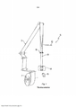
[02] Em acondicionamento de produtos líquidos, por exemplo, em acondicionamento de alimentos líquidos, um material de acondicionamento com base em papelão é frequentemente utilizado para formar os pacotes finais. FIG. 1 mostra um exemplo de um tal sistema. O material de acondicionamento pode ser provido como folhas individuais para criar embalagens individuais em uma máquina de enchimento, ou como uma rede de material que é introduzida em uma máquina de enchimento. A rede de material de acondicionamento é normalmente distribuída em rolos grandes 7, dos quais a máquina de enchimento está configurada para alimentar o material de acondicionamento 3 através de várias estações de tratamento, tais como esterilizadores, seções de formação 8, seções de enchimento 10 e seções de distribuição da máquina de enchimento.[02] In liquid product packaging, for example, in liquid food packaging, a cardboard-based packaging material is often used to form the final packages. FIG. 1 shows an example of such a system. The packaging material can be provided as individual sheets to create individual packages in a filling machine, or as a web of material that is fed into a filling machine. The net of packaging material is normally distributed in
[03] O material de acondicionamento pode ser formado em um tubo de extremidade aberta. O tubo está disposto verticalmente na máquina de enchimento 10 e está sujeito a enchimento contínuo à medida que o material de acondicionamento é transportado através da máquina de enchimento. À medida que o material de acondicionamento, e assim o tubo, se move, as vedações transversais 14 são providas para formar embalagens individuais do tubo. Cada embalagem é separada do tubo por uma garra de vedação 14 que funciona para prover também um corte transversal na área de vedação e as embalagens individuais 15 são transportadas para permitir que as embalagens subsequentes sejam separadas do tubo.[03] The packaging material can be formed into an open-ended tube. The tube is disposed vertically in the
[04] O tubo é formado pela disposição das extremidades laterais do material de acondicionamento de tal modo que se sobrepõem e pela vedação das extremidades laterais uma à outra para criar uma conexão estanque a fluido entre as extremidades laterais.[04] The tube is formed by arranging the side ends of the packaging material such that they overlap and sealing the side ends together to create a fluid-tight connection between the side ends.
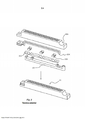
[05] Os dispositivos de aquecimento por indução para vedação transversal são normalmente constituídos por cinco componentes individuais, como mostrado na Fig. 2. Uma estrutura de base 201 geralmente feita de alumínio suporta um núcleo de montagem 202 que é tipicamente feito de sulfureto de polifenileno (PPS). Um número de insertos 203 de material magnético flexível são providos no núcleo de montagem, para impulsionar localmente o campo magnético do dispositivo de aquecimento por indução e assim aumentar a potência induzida na camada condutora da embalagem levando a um aumento local da potência de aproximadamente 30%. Uma bobina 204 é disposta adjacente aos insertos 203 e, finalmente, uma estrutura de corpo 205 encerra todos os outros componentes. De modo semelhante ao núcleo de montagem 202, a estrutura de corpo 205 pode ser feita de PPS. Normalmente, este dispositivo de aquecimento indutor 20 é fabricado montando a estrutura de base 201, o núcleo 202, o(s) inserto(s) 203 e a bobina 204 juntos em um molde, seguido pela moldagem por injeção da estrutura de corpo 205 sobre os componentes montados. Estado da técnica adicional é refletido pelos documentos patentários EP 1 413 520 A1 e EP 0 212 490 A2.[05] Induction heating devices for transverse sealing are typically made up of five individual components, as shown in Fig. 2. A base frame 201 generally made of aluminum supports a mounting core 202 which is typically made of polyphenylene sulfide (PPS). A number of
[06] Até à data, os insertos magnéticos 203 são fabricados sinterizando um material magnético flexível em peças rígidas. O processo de sinterização é um método muito dispendioso, que requer equipamento avançado enquanto restringe a liberdade de concepção para o formato dos insertos 203.[06] To date,
[07] Além disso, dispositivos de aquecimento por indução conhecidos têm uma expectativa de tempo de vida limitada. Ao longo do tempo, a estrutura do corpo torna-se fatigada devido à ação de pressão intermitente no rolo de material de acondicionamento que é necessário para prover a vedação transversal.[07] Furthermore, known induction heating devices have a limited life expectancy. Over time, the body structure becomes fatigued due to the intermittent pressure action on the roll of packaging material that is necessary to provide the transverse seal.
[08] Assim, seria vantajosa uma solução melhorada para insertos magnéticos bem como dispositivos de aquecimento por indução utilizando tais insertos magnéticos.[08] Thus, an improved solution for magnetic inserts as well as induction heating devices using such magnetic inserts would be advantageous.
[09] É, portanto, um objetivo da presente invenção superar ou aliviar os problemas descritos acima.[09] It is, therefore, an objective of the present invention to overcome or alleviate the problems described above.
[10] De acordo com um primeiro aspecto, um Inserto magnético para intensificar o campo magnético de um dispositivo de aquecimento por indução é provido. O inserto magnético é fabricado através do uso de uma composição compreendendo uma matriz de polímero moldável e um material magnético flexível.[10] According to a first aspect, a magnetic Insert for intensifying the magnetic field of an induction heating device is provided. The magnetic insert is manufactured using a composition comprising a moldable polymer matrix and a flexible magnetic material.
[11] Em uma modalidade, a matriz de polímero moldável compreende PPS que é um material durável comprovadamente eficiente em aplicações de alta velocidade tais como provendo vedações transversais em acondicionamento de alimentos líquidos.[11] In one embodiment, the moldable polymer matrix comprises PPS which is a durable material proven to be effective in high speed applications such as providing cross seals in liquid food packaging.
[12] O material magnético pode compreender ferrita de NiZn. A concentração do material magnético flexível pode ser preferivelmente de 30 a 70 por cento de volume.[12] The magnetic material may comprise NiZn ferrite. The concentration of the flexible magnetic material may preferably be from 30 to 70 percent by volume.
[13] Dependendo da aplicação particular, requerendo propriedades diferentes do inserto magnético, o intervalo escolhido permite comprovadamente eficiente fabricação devido à porcentagem relativamente alta da matriz de polímero, enquanto ainda provê a permeabilidade desejada.[13] Depending on the particular application, requiring different properties of the magnetic insert, the range chosen allows for proven efficient fabrication due to the relatively high percentage of polymer matrix, while still providing the desired permeability.
[14] A matriz de polímero pode ser preferivelmente moldável por injeção, por formação térmica, e/ ou moldável por transferência. Em outra modalidade, a matriz de polímero pode ser selecionada como sendo impressa usando impressoras 3D disponíveis.[14] The polymer matrix may preferably be injection moldable, thermally formed, and/or transfer moldable. In another embodiment, the polymer matrix can be selected as being printed using available 3D printers.
[15] De acordo com um segundo aspecto, um método para fabricar um inserto magnético para um dispositivo de aquecimento por indução é provido. O método compreende as etapas de prover uma composição compreendendo uma matriz de polímero moldável e um material magnético flexível, e formar a dita composição no dito inserto magnético.[15] According to a second aspect, a method for fabricating a magnetic insert for an induction heating device is provided. The method comprises the steps of providing a composition comprising a moldable polymer matrix and a flexible magnetic material, and forming said composition in said magnetic insert.
[16] A etapa de formação da dita composição pode ser realizada por moldagem por injeção, formação térmica, moldagem por transferência ou impressão em 3D.[16] The step of forming said composition can be performed by injection molding, thermal forming, transfer molding or 3D printing.
[17] De acordo com um terceiro aspecto, um dispositivo de aquecimento por indução para vedar duas camadas de um material de acondicionamento é provido. O dispositivo de aquecimento por indução compreende uma estrutura de base suportando um inserto magnético de acordo com o primeiro aspecto; uma bobina para induzir um campo magnético e arranjada em um lado do inserto magnético oposto à estrutura de base; e uma estrutura de corpo arranjada para envolver o inserto magnético e a bobina quando montados.[17] According to a third aspect, an induction heating device for sealing two layers of a packaging material is provided. The induction heating device comprises a base structure supporting a magnetic insert according to the first aspect; a coil for inducing a magnetic field and arranged on a side of the magnetic insert opposite the base frame; and a body structure arranged to enclose the magnetic insert and coil when assembled.
[18] O inserto magnético pode ser moldado por injeção entre a estrutura de base e a bobina.[18] The magnetic insert can be injection molded between the base frame and the coil.
[19] Em uma modalidade, o inserto magnético se estende sobre uma superfície de topo da estrutura de base confrontando a bobina.[19] In one embodiment, the magnetic insert extends over a top surface of the base frame facing the coil.
[20] O inserto magnético pode ser formado com um padrão de rebaixo para receber a bobina.[20] The magnetic insert can be formed with a recess pattern to receive the coil.
[21] Em uma modalidade preferida, a estrutura de base é feita de aço inoxidável.[21] In a preferred embodiment, the base frame is made of stainless steel.
[22] O inserto magnético pode ser arranjado com pelo menos uma protuberância arredondada, biselada ou chanfrada em uma superfície de topo do mesmo, e em alguma modalidade, o inserto magnético se estende ao longo do comprimento da bobina.[22] The magnetic insert may be arranged with at least one rounded, beveled, or chamfered protrusion on a top surface of the insert, and in some embodiment, the magnetic insert extends along the length of the coil.
[23] De acordo com um quarto aspecto, um método para a fabricação de um dispositivo de aquecimento por indução é provido. O método compreende as etapas de montagem de uma estrutura de base e de uma bobina em um primeiro molde; moldagem por injeção de um inserto magnético de acordo com o primeiro aspecto entre a estrutura de base e a bobina, resultando em um primeiro componente; montagem do dito primeiro componente em um segundo molde; e moldagem por injeção de uma estrutura de corpo no primeiro componente, dessa forma formando o dito dispositivo de aquecimento por indução.[23] According to a fourth aspect, a method for manufacturing an induction heating device is provided. The method comprises the steps of assembling a base frame and a coil in a first mold; injection molding a magnetic insert according to the first aspect between the base frame and the coil, resulting in a first component; assembling said first component into a second mold; and injection molding a body structure into the first component, thereby forming said induction heating device.
[24] O método pode compreender adicionalmente a etapa de formação da estrutura de base de aço inoxidável.[24] The method may further comprise the step of forming the stainless steel base frame.
[25] O que foi citado acima, assim como outros objetivos, características e vantagens da presente invenção, serão melhor compreendidos através da seguinte descrição detalhada ilustrativa e não limitativa de modalidades preferidas da presente invenção, com referência aos desenhos anexos, nos quais: a FIG. 1 é uma vista esquemática de uma máquina de enchimento de produtos líquidos da técnica anterior; a FIG. 2 é uma vista esquemática de um dispositivo de aquecimento por indução da técnica anterior para prover uma vedação transversal em uma embalagem; a FIG. 3 é uma vista esquemática de um dispositivo de aquecimento por indução de acordo com uma modalidade; a FIG. 4 é uma vista lateral esquemática do inserto magnético sendo provido de protuberâncias arredondadas de acordo com uma modalidade; e a FIG. 5 é fluxograma de um método de acordo com uma modalidade.[25] The foregoing, as well as other objectives, characteristics and advantages of the present invention, will be better understood through the following illustrative and non-limiting detailed description of preferred embodiments of the present invention, with reference to the attached drawings, in which: a FIG. 1 is a schematic view of a prior art liquid product filling machine; FIG. 2 is a schematic view of a prior art induction heating device for providing a transverse seal on a package; FIG. 3 is a schematic view of an induction heating device according to an embodiment; FIG. 4 is a schematic side view of the magnetic insert being provided with rounded protrusions in accordance with an embodiment; and FIG. 5 is flowchart of a method according to an embodiment.
[26] Como um princípio geral, a solução proposta de formar o inserto magnético de uma composição compreendendo uma matriz de polímero moldável e um material magnético flexível resultará em uma série de benefícios em comparação com soluções previamente conhecidas. Para começar, a escolha do material permitirá que insertos magnéticos sejam produzidos por equipamento de alta velocidade, tal como moldagem por injeção, etc. Além disso, não existem restrições quanto à forma e dimensões, pelo que as dimensões dos insertos magnéticos podem ser projetadas livremente.[26] As a general principle, the proposed solution of forming the magnetic insert of a composition comprising a moldable polymer matrix and a flexible magnetic material will result in a number of benefits compared to previously known solutions. For starters, the choice of material will allow magnetic inserts to be produced by high speed equipment such as injection molding etc. Furthermore, there are no restrictions on shape and dimensions, so the dimensions of the magnetic inserts can be freely designed.
[27] Tendo em conta estas vantagens, uma ideia é prover um dispositivo de aquecimento por indução que seja mais robusto mecanicanicamente e que tenha um design flexível. Esta ideia é posta em prática provendo um dispositivo de aquecimento por indução tendo uma estrutura de base com durabilidade melhorada tendo em vista as soluções comuns usando PPS. Uma tal estrutura de base pode ser um material metálico, tal como aço inoxidável.[27] In view of these advantages, one idea is to provide an induction heating device that is mechanically more robust and has a flexible design. This idea is put into practice by providing an induction heating device having a base structure with improved durability in view of common solutions using PPS. Such a base structure can be a metallic material such as stainless steel.
[28] De modo a não afetar negativamente as capacidades de aquecimento por indução, a estrutura de base metálica é de preferência protegida da bobina por meio de uma blindagem magnética. A blindagem magnética deve, para esta finalidade, estender-se ao longo do comprimento da bobina, de modo que a blindagem forme uma barreira física entre a bobina e a estrutura de base. Devido à nova técnica para prover os insertos magnéticos, verificou-se que tal inserto magnético provido como uma estrutura alongada, pode realmente formar tal blindagem de uma maneira muito eficiente. Os insertos magnéticos propostos, assim, não só permitem uma fabricação mais eficiente, mas também permitem uma base metálica do dispositivo de aquecimento por indução, o que até hoje não foi possível.[28] In order not to negatively affect induction heating capabilities, the metallic base structure is preferably protected from the coil by means of a magnetic shield. The magnetic shield must, for this purpose, extend along the length of the coil so that the shield forms a physical barrier between the coil and the base structure. Due to the new technique for providing the magnetic inserts, it has been found that such a magnetic insert provided as an elongated structure, can actually form such shield in a very efficient way. The proposed magnetic inserts thus not only allow a more efficient fabrication, but also allow a metallic base of the induction heating device, which until today has not been possible.
[29] De modo a poder prover uma vedação transversal na embalagem utilizando indução, a embalagem é provida com uma camada condutora que interage com o campo magnético criado pelo dispositivo de aquecimento por indução. Esta interação irá gerar correntes de Foucault na camada condutora do material de acondicionamento, o que devido à resistência intrínseca da camada condutora irá aumentar a temperatura no material de acondicionamento localmente na posição da vedação, pelo que o aumento da temperatura é utilizado para fundir as camadas poliméricas do material de acondicionamento para laminar o material de acondicionamento.[29] In order to be able to provide a transverse seal on the package using induction, the package is provided with a conductive layer that interacts with the magnetic field created by the induction heating device. This interaction will generate eddy currents in the conductive layer of the packaging material, which due to the intrinsic resistance of the conductive layer will increase the temperature in the packaging material locally at the seal position, so the temperature rise is used to fuse the layers packaging material to laminate the packaging material.
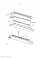
[30] Em uma modalidade, de acordo com a Fig. 3, é mostrado um dispositivo de aquecimento por indução 30. O dispositivo de aquecimento por indução compreende uma estrutura de base 301, de preferência formada por um material metálico rígido e durável tal como aço inoxidável. O dispositivo de aquecimento por indução 30 compreende ainda um inserto magnético 302 que está disposto na estrutura de base 301. O inserto magnético 302 é formado por uma composição compreendendo uma matriz de polímero moldável e um material magnético flexível. De preferência, a concentração do material magnético flexível é escolhida de modo a situar-se no intervalo de 30-70 por cento em volume, e em uma modalidade mais preferida entre 50-70 por cento em volume.[30] In one embodiment, according to Fig. 3, an
[31] Uma bobina 303 está disposta sobre o inserto magnético 302 em um lado oposto ao do material de base, de modo que o inserto magnético 302 atua para blindar a estrutura de base metálica da bobina. Quando a corrente está fluindo através da bobina 303, as propriedades magnéticas do inserto magnético 302, causadas pela provisão do material magnético flexível, aumentarão de fato a eficiência do dispositivo de aquecimento por indução 30. Como o material magnético flexível do inserto magnético 302 afeta a permeabilidade do inserto magnético, uma maior permeabilidade permite que mais campo magnético passe através dele, ou seja, menos campo escapa para o corpo de aço inoxidável, o que causaria perdas de calor.[31] A
[32] Além disso, o dispositivo de aquecimento por indução 30 compreende uma estrutura de corpo 304 que está disposta bastante próxima à bobina 303, e sendo provida para formar um corpo rígido. A estrutura do corpo deve ser preferencialmente feita de um material rígido capaz de suportar carga repetida, tal como o caso quando usado em máquinas de enchimento de alta velocidade. Por conseguinte, a estrutura de corpo 304 pode ser fabricada de um composto compreendendo PPS e fibra de vidro, de preferência por moldagem por injeção do composto em um molde que acomoda a estrutura de base 301, o inserto magnético 302 e a bobina 303.[32] Furthermore, the
[33] O inserto magnético 302 compreende um material magnético flexível. O material utilizado para o inserto magnético 302 pode ser escolhido devido a requisitos específicos da aplicação particular. Por exemplo, o inserto magnético 302 pode ser formado de um composto compreendendo PPS e ferrita NiZn, em que a concentração da ferrita NiZn está compreendida entre 30 e 70 por cento em volume, de preferência entre 50 e 70 por cento em volume.[33]
[34] A funcionalidade do inserto magnético é pelo menos dupla. Em primeiro lugar, a estrutura de base metálica 301 é blindada contra a qual é impedida ou pelo menos limitada de afetar negativamente os campos magnéticos associados à bobina em utilização. Em segundo lugar, o material magnético flexível do inserto magnético 302 atua para aumentar o campo magnético da bobina ou, em outras palavras, permitir moldar o campo magnético em uma forma desejada que permite uma funcionalidade de vedação transversal melhorada. Assim, utilizando o inserto magnético 302, não há necessidade de utilizar insertos separados como em soluções conhecidas.[34] The functionality of the magnetic insert is at least twofold. First, the
[35] Em uma modalidade, o material magnético flexível do inserto magnético compreende uma matriz de polímero provida com partículas magnéticas flexíveis. A matriz polimérica pode compreender sulfureto de polifenileno (PPS), enquanto que o inserto magnético 392 pode ser moldável por várias técnicas, tais como moldagem por injeção, formação térmica, moldagem por transferência, impressão em 3D, etc.[35] In one embodiment, the flexible magnetic material of the magnetic insert comprises a polymer matrix provided with flexible magnetic particles. The polymer matrix can comprise polyphenylene sulfide (PPS), while the magnetic insert 392 can be moldable by various techniques, such as injection molding, thermal forming, transfer molding, 3D printing, etc.
[36] Em uma modalidade, o inserto magnético 302 estende-se sobre uma superfície de topo da estrutura de base 301 confrontando a bobina 303.[36] In one embodiment,
[37] Em uma modalidade, o inserto magnético 302 está disposto em um formato tal que quando a bobina 303 está disposta no inserto magnético 302, o inserto magnético 302 blinda a bobina 303 da estrutura de base 301 em qualquer direção linear da bobina 303 para a estrutura de base 301.[37] In one embodiment,
[38] Em uma modalidade, o inserto magnético 302 tem uma forma com um padrão de rebaixo para receber a bobina 303, em um encaixe preferencialmente apertado. O padrão de rebaixo estende-se de preferência em uma parte central do inserto magnético 302 substancialmente ao longo de todo o comprimento do inserto magnético 302, de tal modo que o padrão de rebaixo pode ser formado moldando o inserto magnético 302 parcialmente em torno da bobina 303.[38] In one embodiment,
[39] Em uma modalidade, o inserto magnético 302 é moldável por injeção. Utilizando a moldagem por injeção, o inserto magnético 302 pode ser moldado diretamente na bobina 303, aumentando assim a eficiência do indutor. Em relação às soluções de corrente, o inserto magnético moldado por injeção 302 reduz o número de componentes internos, uma vez que a necessidade de insertos separados é removida. Um número reduzido de componentes internos torna o projeto mais robusto, uma vez que o material moldado por injeção terá um volume mais homogêneo para preencher. Além disso, o tempo de fabricação é reduzido uma vez que a necessidade de montagem manual das inserções é removida. Como resultado da redução do trabalho manual, o risco de erros também é reduzido durante a fabricação.[39] In one embodiment, the
[40] O inserto magnético 302 pode ser moldado por injeção utilizando uma ferramenta de moldagem por injeção, na qual a estrutura de base 301 e a bobina 303 estão montadas. Uma vez que o inserto magnético 302 é moldado diretamente durante o processo de moldagem por injeção na ferramenta de moldagem por injeção, os problemas da cadeia de tolerância podem ser evitados.[40]
[41] A moldagem por injeção do inserto magnético 302 também permite uma compensação na vedação de áreas críticas, uma vez que o formato do inserto magnético 302 pode ser escolhido de modo que uma quantidade aumentada de material esteja disposta em posições críticas, por exemplo, nas extremidades laterais, bem como na posição da sobreposição de vedação longitudinal.[41] Injection molding of
[42] Em uma modalidade, a estrutura de base é feita de aço inoxidável. Uma estrutura de base feita de aço inoxidável tem uma expectativa de vida melhor do que as estruturas de base de alumínio normalmente conhecidas. De preferência, a estrutura de base não deve ser magnética uma vez que isso afeta negativamente a eficiência do indutor. Dependendo dos requisitos da aplicação final, um material deve ser escolhido. O alumínio pode muito bem ser totalmente adequado para algumas aplicações onde as condições ambientais são menos severas. Nas soluções da técnica anterior, as inserções de ímã 302 têm transições acentuadas devido à fabricação por processos de sinterização. Tais bordas afiadas são limitantes para o número de opções de concepção, devido ao fato de que tais bordas afiadas podem dar origem a rachaduras e fadiga do material no corpo de polímero 205. Além disso, as bordas afiadas das inserções 203 podem causar distribuição não desejada do campo magnético, onde as perdas ocorrerão.[42] In one embodiment, the base frame is made of stainless steel. A base frame made of stainless steel has a better life expectancy than commonly known aluminum base frames. Preferably, the scaffold should not be magnetic as this negatively affects the efficiency of the inductor. Depending on the requirements of the final application, a material must be chosen. Aluminum may well be quite suitable for some applications where environmental conditions are less severe. In prior art solutions, magnet inserts 302 have sharp transitions due to fabrication by sintering processes. Such sharp edges are limiting the number of design options due to the fact that such sharp edges can give rise to cracking and material fatigue in
[43] Em uma modalidade o inserto magnético 302 está disposto com um em número de protuberâncias 321 em uma superfície de topo do mesmo. As protuberâncias são arredondadas, biseladas ou chanfradas para permitir um melhor desempenho, uma vez que isto permite adaptar o formato de um campo magnético desejado utilizado para a vedação transversal. Em outras palavras, as protuberâncias são dispostas com transições suaves por duas razões; I) o corpo 304 terá um comprimento de vida aumentado, e ii) o campo magnético gerado pode ter uma eficiência aumentada. Consequentemente, utilizando a moldagem por injeção, o inserto magnético pode ser disposto em uma forma que pode moldar o campo magnético com a quantidade certa de energia em cada ponto ao longo do inserto magnético. O uso de protuberâncias arredondadas, biseladas ou chanfradas reduz ainda mais o risco de rachaduras internas devido à ausência de bordas afiadas, o que aumenta a expectativa de vida útil do inserto magnético. Além disso, tal inserto magnético permite perdas resistivas reduzidas internamente no indutor, de modo que a temperatura interna é reduzida.[43] In one embodiment the
[44] Em uma modalidade, o dispositivo de aquecimento por indução é fabricado por um processo de moldagem de dois componentes, em que o primeiro componente compreende moldar o inserto magnético à bobina montada e à estrutura de base, e o segundo componente seria moldar a estrutura do corpo sobre o primeiro componente. Tal processo de fabricação pode ser automatizado a um grau muito mais elevado em comparação com soluções conhecidas.[44] In one embodiment, the induction heating device is manufactured by a two-component molding process, wherein the first component comprises molding the magnetic insert to the assembled coil and base frame, and the second component would be molding the body structure on the first component. Such a manufacturing process can be automated to a much higher degree compared to known solutions.
[45] Em uma modalidade, de acordo com a Fig. 4, é provido um método 50 de fabricação de um dispositivo de aquecimento por indução. O método compreende a etapa 51 de montagem de uma estrutura de base 301 e de uma bobina 303 em um primeiro suporte. O método compreende ainda uma etapa 52 de moldagem por injeção de um inserto magnético 302 entre a estrutura de base 301 e a bobina 303, resultando em um primeiro componente. Além disso, o método compreende uma etapa 53 de arranjar o primeiro componente em um segundo molde e uma etapa 54 de moldagem por injeção de uma estrutura de corpo 304 ao primeiro componente em um segundo suporte, formando assim o dito dispositivo de aquecimento por indução.[45] In one embodiment, according to Fig. 4, a
[46] Embora a descrição acima tenha sido feita principalmente com referência a um dispositivo de aquecimento por indução para vedação transversal de uma embalagem, deve ser apreciado que o dispositivo de aquecimento por indução descrito pode ser utilizado em muitas outras aplicações de vedação em que é desejada a vedação por indução.[46] Although the above description has been made primarily with reference to an induction heating device for transversely sealing a package, it should be appreciated that the induction heating device described can be used in many other sealing applications where it is induction sealing is desired.
[47] Além disso, a invenção foi principalmente descrita com referência a algumas modalidades. No entanto, tal como é facilmente compreendido por um especialista na técnica, são igualmente possíveis outras modalidades do que as descritas acima no âmbito da invenção, tal como definido nas reivindicações anexas.[47] Furthermore, the invention has mainly been described with reference to some modalities. However, as is readily understood by a person skilled in the art, other embodiments than those described above are also possible within the scope of the invention as defined in the appended claims.
Claims (12)
Applications Claiming Priority (3)
| Application Number | Priority Date | Filing Date | Title |
|---|---|---|---|
| SE1450723-0 | 2014-06-12 | ||
| SE1450723 | 2014-06-12 | ||
| PCT/EP2015/062906 WO2015189253A1 (en) | 2014-06-12 | 2015-06-10 | An induction heating device |
Publications (2)
| Publication Number | Publication Date |
|---|---|
| BR112016028208A2 BR112016028208A2 (en) | 2017-08-22 |
| BR112016028208B1 true BR112016028208B1 (en) | 2021-10-13 |
Family
ID=53404527
Family Applications (1)
| Application Number | Title | Priority Date | Filing Date |
|---|---|---|---|
| BR112016028208-6A BR112016028208B1 (en) | 2014-06-12 | 2015-06-10 | INDUCTION HEATING DEVICE, AND, METHOD FOR MAKING AN INDUCTION HEATING DEVICE |
Country Status (9)
| Country | Link |
|---|---|
| US (1) | US10322546B2 (en) |
| EP (1) | EP3154767B1 (en) |
| JP (1) | JP6696913B2 (en) |
| KR (1) | KR20170017900A (en) |
| CN (1) | CN106573415B (en) |
| BR (1) | BR112016028208B1 (en) |
| MX (1) | MX2016015348A (en) |
| RU (1) | RU2016148382A (en) |
| WO (1) | WO2015189253A1 (en) |
Families Citing this family (5)
| Publication number | Priority date | Publication date | Assignee | Title |
|---|---|---|---|---|
| EP3241667B1 (en) | 2016-05-02 | 2020-07-08 | Tetra Laval Holdings & Finance S.A. | Improved induction sealing system |
| JP6563612B2 (en) * | 2016-12-28 | 2019-08-21 | 株式会社森傳 | Vehicle interior board and manufacturing method thereof |
| JP2023547052A (en) * | 2020-11-06 | 2023-11-09 | テトラ ラバル ホールディングス アンド ファイナンス エス エイ | induction sealing device |
| US11865791B2 (en) * | 2021-12-30 | 2024-01-09 | Rohr, Inc. | Induction welding with an electromagnetic field concentrator |
| CN117622633B (en) * | 2024-01-25 | 2024-03-29 | 晋江美达兴包装彩印有限公司 | Packaging bag edge sealing hot pressing device |
Family Cites Families (18)
| Publication number | Priority date | Publication date | Assignee | Title |
|---|---|---|---|---|
| US3808074A (en) * | 1970-11-06 | 1974-04-30 | United Glass Ltd | Induction heat sealing of a container |
| US4169004A (en) * | 1975-09-24 | 1979-09-25 | The Procter & Gamble Company | Water frangible end seal for hydro-dissociative agglomerate tampon |
| SE451974B (en) | 1985-08-22 | 1987-11-09 | Tetra Pak Ab | SET AND DEVICE FOR INDUCTION SEALING THERMOPLAST COATED PACKAGING MATERIAL INCLUDING ATMINSTONE ONE LAYER OF METAL WRAP |
| JP2001168575A (en) | 1999-12-08 | 2001-06-22 | Sony Corp | Radio wave absorber and method of its manufacture |
| EP1326741B1 (en) | 2000-05-02 | 2006-08-09 | Ashland Inc. | Temperature-controlled induction heating of polymeric materials |
| RU2301730C2 (en) | 2001-12-20 | 2007-06-27 | Эйшапак Холдинг Са | Package material heat sealing apparatus |
| US6872325B2 (en) * | 2002-09-09 | 2005-03-29 | General Electric Company | Polymeric resin bonded magnets |
| ES2266382T3 (en) | 2002-10-24 | 2007-03-01 | TETRA LAVAL HOLDINGS & FINANCE S.A. | WELDING GRIP. |
| JP2004228043A (en) | 2003-01-27 | 2004-08-12 | Canon Inc | Heating device of electromagnetic induction heating method, magnetic path forming member used for the device, and image forming apparatus |
| US20060154052A1 (en) * | 2003-07-03 | 2006-07-13 | Koninklijke Philips Electronics N.V. | Soft magnetic material for manufacturing printed circuit boards |
| EP1541641A1 (en) | 2003-12-05 | 2005-06-15 | Rohm And Haas Company | Induction cured power coatings for temperature sensitive substrates |
| EP2008795B1 (en) * | 2007-06-28 | 2011-08-31 | Tetra Laval Holdings & Finance SA | Induction sealing device for heat sealing packaging material for producing sealed packages of pourable food products |
| DE102007059812A1 (en) * | 2007-12-11 | 2009-06-18 | Multivac Sepp Haggenmüller Gmbh & Co. Kg | Packaging machine with induction heating |
| TWI405225B (en) * | 2008-02-22 | 2013-08-11 | Cyntec Co Ltd | Choke coil |
| WO2012019925A1 (en) | 2010-08-09 | 2012-02-16 | Tetra Laval Holdings & Finance S.A. | An inductor for sealing packages |
| EP3409451B1 (en) * | 2010-12-23 | 2019-11-20 | Tetra Laval Holdings & Finance S.A. | Induction sealing device for heat sealing packaging material for producing sealed packages of pourable food products |
| CN102181156B (en) | 2011-05-25 | 2013-01-30 | 深圳市科聚新材料有限公司 | Polyphenylene sulfide composite material and preparation method thereof |
| GB2506681A (en) | 2012-10-08 | 2014-04-09 | Vacuumschmelze Gmbh & Co Kg | Soft anisotropic magnetic material article and method for its production |
-
2015
- 2015-06-10 RU RU2016148382A patent/RU2016148382A/en not_active Application Discontinuation
- 2015-06-10 US US15/317,640 patent/US10322546B2/en active Active
- 2015-06-10 WO PCT/EP2015/062906 patent/WO2015189253A1/en active Application Filing
- 2015-06-10 BR BR112016028208-6A patent/BR112016028208B1/en active IP Right Grant
- 2015-06-10 CN CN201580031130.4A patent/CN106573415B/en active Active
- 2015-06-10 JP JP2016572471A patent/JP6696913B2/en active Active
- 2015-06-10 EP EP15729413.3A patent/EP3154767B1/en active Active
- 2015-06-10 MX MX2016015348A patent/MX2016015348A/en unknown
- 2015-06-10 KR KR1020167033850A patent/KR20170017900A/en unknown
Also Published As
| Publication number | Publication date |
|---|---|
| CN106573415A (en) | 2017-04-19 |
| MX2016015348A (en) | 2017-04-13 |
| RU2016148382A (en) | 2018-07-18 |
| EP3154767B1 (en) | 2019-11-20 |
| BR112016028208A2 (en) | 2017-08-22 |
| KR20170017900A (en) | 2017-02-15 |
| CN106573415B (en) | 2019-10-25 |
| EP3154767A1 (en) | 2017-04-19 |
| US10322546B2 (en) | 2019-06-18 |
| JP6696913B2 (en) | 2020-05-20 |
| RU2016148382A3 (en) | 2018-11-07 |
| JP2017519340A (en) | 2017-07-13 |
| WO2015189253A1 (en) | 2015-12-17 |
| US20170120506A1 (en) | 2017-05-04 |
Similar Documents
| Publication | Publication Date | Title |
|---|---|---|
| BR112016028208B1 (en) | INDUCTION HEATING DEVICE, AND, METHOD FOR MAKING AN INDUCTION HEATING DEVICE | |
| US9470768B2 (en) | Cooling device for a gradient coil and use thereof | |
| BR112019018531A2 (en) | multilayer susceptor set for inductive heating of an aerosol-forming substrate | |
| CN104412705A (en) | Quick heating and cooling mould | |
| BR112019020005A2 (en) | multilayer susceptor set for inductive heating of an aerosol-forming substrate | |
| CN109263055B (en) | Induction sealing device | |
| DK2938473T3 (en) | DEVICE AND PROCEDURE FOR HEATING A FORM OR TOOL | |
| JP2009200435A5 (en) | ||
| RU2015144908A (en) | PRINTING BEAM | |
| CN1309525C (en) | Heat-sealing device for packaging material | |
| CN109262128B (en) | Inductor coil for induction welding packaging material | |
| JP2017163734A (en) | Manufacturing method of rotor for rotary electric machine, and rotor of rotary electric machine | |
| WO2007081918A2 (en) | Electromagnetically shielded induction heating apparatus | |
| CN107462850A (en) | Gradient coil assembly | |
| CN107926087B (en) | Induction type crucible furnace | |
| CN102653109A (en) | Method to manufacture a sensor | |
| CN105097233B (en) | Transformer with anticracking bobbin, low-voltage direct-current converter and its assemble method | |
| JP2014180759A (en) | Metal part insert molding method for thermoplastic resin and mold for the same | |
| IT201900012903A1 (en) | ELECTRIC HEATER | |
| JP6586371B2 (en) | Heating coil | |
| JP5907332B2 (en) | Crankshaft induction hardening method and induction induction heating coil | |
| JP5131232B2 (en) | Transverse induction heating device | |
| JP7330457B2 (en) | heating device | |
| BR102018005572A2 (en) | reactor manufacturing method and heating device | |
| JP2004206901A (en) | Induction heating device |
Legal Events
| Date | Code | Title | Description |
|---|---|---|---|
| B06U | Preliminary requirement: requests with searches performed by other patent offices: procedure suspended [chapter 6.21 patent gazette] | ||
| B09A | Decision: intention to grant [chapter 9.1 patent gazette] | ||
| B16A | Patent or certificate of addition of invention granted [chapter 16.1 patent gazette] |
Free format text: PRAZO DE VALIDADE: 20 (VINTE) ANOS CONTADOS A PARTIR DE 10/06/2015, OBSERVADAS AS CONDICOES LEGAIS. |