BR112016020740B1 - HEART STENT VALVE AND APPLICATION SYSTEM FOR SUCH VALVE - Google Patents
HEART STENT VALVE AND APPLICATION SYSTEM FOR SUCH VALVE Download PDFInfo
- Publication number
- BR112016020740B1 BR112016020740B1 BR112016020740-8A BR112016020740A BR112016020740B1 BR 112016020740 B1 BR112016020740 B1 BR 112016020740B1 BR 112016020740 A BR112016020740 A BR 112016020740A BR 112016020740 B1 BR112016020740 B1 BR 112016020740B1
- Authority
- BR
- Brazil
- Prior art keywords
- stent
- valve
- follicle
- component
- attachment
- Prior art date
Links
- 210000002216 Heart Anatomy 0.000 title abstract description 8
- 210000001519 tissues Anatomy 0.000 claims description 33
- 230000001746 atrial Effects 0.000 claims description 15
- 230000000747 cardiac effect Effects 0.000 claims description 3
- 210000004115 Mitral Valve Anatomy 0.000 abstract description 5
- 210000003709 Heart Valves Anatomy 0.000 abstract description 2
- 230000002861 ventricular Effects 0.000 description 12
- 210000004369 Blood Anatomy 0.000 description 8
- 239000008280 blood Substances 0.000 description 8
- 230000017531 blood circulation Effects 0.000 description 8
- 210000001308 Heart Ventricles Anatomy 0.000 description 6
- 238000004873 anchoring Methods 0.000 description 6
- 239000000463 material Substances 0.000 description 4
- 238000001356 surgical procedure Methods 0.000 description 4
- 230000035488 systolic blood pressure Effects 0.000 description 4
- 230000035695 Efflux Effects 0.000 description 3
- 210000002837 Heart Atria Anatomy 0.000 description 3
- 210000003516 Pericardium Anatomy 0.000 description 3
- 210000000038 chest Anatomy 0.000 description 3
- 238000010276 construction Methods 0.000 description 3
- 239000004744 fabric Substances 0.000 description 3
- 238000002513 implantation Methods 0.000 description 3
- 239000000203 mixture Substances 0.000 description 3
- 230000002093 peripheral Effects 0.000 description 3
- 210000000709 Aorta Anatomy 0.000 description 2
- 210000001765 Aortic Valve Anatomy 0.000 description 2
- 206010012587 Device leakage Diseases 0.000 description 2
- WYTGDNHDOZPMIW-UHOFOFEASA-O Serpentine Natural products O=C(OC)C=1[C@@H]2[C@@H]([C@@H](C)OC=1)C[n+]1c(c3[nH]c4c(c3cc1)cccc4)C2 WYTGDNHDOZPMIW-UHOFOFEASA-O 0.000 description 2
- 229910001000 nickel titanium Inorganic materials 0.000 description 2
- 229920002994 synthetic fiber Polymers 0.000 description 2
- 210000003484 anatomy Anatomy 0.000 description 1
- 238000005452 bending Methods 0.000 description 1
- 239000000560 biocompatible material Substances 0.000 description 1
- 230000000271 cardiovascular Effects 0.000 description 1
- 201000009910 diseases by infectious agent Diseases 0.000 description 1
- 230000000694 effects Effects 0.000 description 1
- 239000012530 fluid Substances 0.000 description 1
- 238000003384 imaging method Methods 0.000 description 1
- 230000001788 irregular Effects 0.000 description 1
- 229910052751 metal Inorganic materials 0.000 description 1
- 239000002184 metal Substances 0.000 description 1
- 229910001092 metal group alloy Inorganic materials 0.000 description 1
- 150000002739 metals Chemical class 0.000 description 1
- 238000000034 method Methods 0.000 description 1
- 238000010992 reflux Methods 0.000 description 1
- 238000007789 sealing Methods 0.000 description 1
- 238000009958 sewing Methods 0.000 description 1
- 238000011105 stabilization Methods 0.000 description 1
- 230000002792 vascular Effects 0.000 description 1
Images


Abstract
VÁLVULA-STENT CARDÍACA E DISPOSITIVO DE APLICAÇÃO PARA TAL VÁLVULA. A presente invenção relaciona-se a uma válvula-stent cardíaca (1), preferivelmente uma válvula-stent mitral compreendendo um componente stent (2) e um componente de válvula (3), sendo que o componente stent (2) compreende uma extremidade de influxo (4) e uma extremidade de efluxo (5) e uma parede disposta entre a extremidade de influxo (4) e a extremidade de efluxo (5), e sendo que o componente de válvula (3) é feito de um único folículo (6); a periferia do dito folículo único (6) sendo parcialmente afixada ou afixável ao componente stent (2) ao longo de pelo menos linhas de fixação (7', 7''), caracterizada pelo fato de as ditas duas linhas de fixação (7') serem pelo menos parcialmente inclinadas com relação a um plano anular da dita válvula perpendicular à direção do fluxo (A) através da válvula-stent (1), e de a terceira linha de fixação (7'') correr paralela ao dito plano.HEART STENT VALVE AND APPLICATION DEVICE FOR SUCH VALVE. The present invention relates to a heart valve stent (1), preferably a mitral valve stent comprising a stent component (2) and a valve component (3), the stent component (2) comprising a stent end. inflow (4) and an outflow end (5) and a wall disposed between the inflow end (4) and the outflow end (5), and the valve component (3) being made of a single follicle ( 6); the periphery of said single follicle (6) being partially affixed or affixable to the stent component (2) along at least attachment lines (7', 7''), characterized in that said two attachment lines (7' ) are at least partially inclined with respect to an annular plane of said valve perpendicular to the direction of flow (A) through the stent valve (1), and the third attachment line (7'') runs parallel to said plane.
Description
[001] A presente invenção relaciona-se a válvulas-stent expansíveis e a um dispositivo de suprimento para válvulas-stent expansíveis. Mais precisamente, a presente invenção relaciona-se a válvulas stent cardíacas incluindo um único folículo.[001] The present invention relates to expandable stent valves and a supply device for expandable stent valves. More precisely, the present invention relates to cardiac stent valves including a single follicle.
[002] A substituição de válvulas cardíacas por próteses é uma cirurgia complexa. A substituição frequentemente é realizada através de uma cirurgia de peito aberto. Tal operação requer a abertura do tórax, assim como a captura do coração do paciente.[002] The replacement of heart valves by prostheses is a complex surgery. Replacement is often performed through open-chest surgery. Such an operation requires opening the chest as well as capturing the patient's heart.
[003] A US 4.759.758 sugere uma válvula-stent mitral incluindo um stent e um único flape. O flape é visto em seção transversal do stent por suas abas inferiores para costurar furos que se estendem ao longo de bordas curvadas para baixo do stent.[003] US 4,759,758 suggests a mitral valve-stent including a stent and a single flap. The flap is seen in cross-section of the stent by its lower flaps for sewing holes that extend along the downwardly curved edges of the stent.
[004] A válvula-stent descrita na US 4759758 é uma válvula-stent cirúrgica e costurada a um anel do coração em uma cirurgia de peito aberto. Uma cirurgia de peito aberto é um procedimento importante que pode trazer problemas cirúrgicos, tais como por exemplo, infecções.[004] The valve stent described in US 4759758 is a surgical valve stent and sewn to a heart ring in open chest surgery. Open chest surgery is an important procedure that can lead to surgical problems, such as infections.
[005] Nos últimos anos, sistemas minimamente invasivos foram desenvolvidos para aplicar percutaneamente uma prótese de válvula- stent por meio de cateter.[005] In recent years, minimally invasive systems have been developed to percutaneously apply a valve-stent prosthesis through a catheter.
[006] Stents a serem instalados por cateter devem ser grampeados para serem montados no cateter. Chegando no local de implantação, o stent é liberado e expande quer por autoexpansão ou com ajuda de meios auxiliares, tais como balões ou fios.[006] Stents to be installed by catheter must be stapled to be mounted on the catheter. Arriving at the implantation site, the stent is released and expands either by self-expansion or with the help of auxiliary means such as balloons or wires.
[007] A WO 2009/ 106545 sugere o uso de stents com elementos em forma de dedo provendo uma força de tensão radial sobre a parede vascular. A força de tensão do elemento em forma de dedo ancora o stent.[007] WO 2009/106545 suggests the use of stents with finger-shaped elements providing a radial tension force on the vascular wall. The tensile force of the finger-shaped element anchors the stent.
[008] Outra possibilidade de ancorar stents depende da forma externa do stent para permitir uma ancoragem por forma na anatomia do paciente. A EP 1 893 132 sugere um stent com forma de ampulheta, onde a porção com maior diâmetro provê uma ancoragem do stent por ajuste de forma. A WO 2008/ 028569 sugere prover um orifício arredondado para fixar a válvula-stent por ajuste de forma.[008] Another possibility of anchoring stents depends on the external shape of the stent to allow an anchorage by shape in the patient's anatomy.
[009] A WO 2012/ 063228 propõe uma solução incluindo uma estrutura suporte e um membro de ancoragem. O membro de ancoragem é separado da estrutura suporte e compreende por exemplo um anel. O membro de ancoragem coopera com a parede periférica da estrutura suporte se estendendo ao redor da mesma de modo a travar os folículos de válvula da válvula cardiovascular entre o membro de ancoragem e a parede periférica da estrutura suporte.[009] WO 2012/063228 proposes a solution including a support structure and an anchoring member. The anchoring member is separate from the support structure and comprises for example a ring. The anchoring member cooperates with the peripheral wall of the support structure by extending around it so as to lock the valve follicles of the cardiovascular valve between the anchoring member and the peripheral wall of the support structure.
[0010] No entanto, a construção conforme WO 2012/ 0632228 é complicada, uma vez que há dois membros separados que devem ser conectados dentro do corpo. A combinação tem que ser muito precisa para prover uma ancoragem confiável.[0010] However, the construction according to WO 2012/0632228 is complicated since there are two separate members that must be connected inside the body. The combination has to be very accurate to provide a reliable anchorage.
[0011] Por conseguinte, há necessidade de stents que não tenham a desvantagem do estado da técnica conhecida. Em particular, há necessidade de stents que provenham um sistema de ancoragem confiável de construção simples e eficiente, que seja fácil de usar e não danifique o tecido vizinho.[0011] Therefore, there is a need for stents that do not have the disadvantage of the known state of the art. In particular, there is a need for stents that provide a reliable anchorage system of simple and efficient construction, that is easy to use and does not damage the surrounding tissue.
[0012] Nesta, é geralmente descrita uma válvula stent mitral tendo apenas um folículo. Contudo, deve ser entendido que a invenção também é utilizável para outras válvulas stent cardíacas.[0012] In this, a mitral valve stent having only one follicle is generally described. However, it should be understood that the invention is also usable for other cardiac stent valves.
[0013] O problema é solucionado com uma válvula-stent de acordo com reivindicações independentes da presente invenção, em particular com uma válvula-stent expansível, preferivelmente uma válvula-stent auto expansível. A válvula-stent compreende um componente stent e um componente de válvula. O componente stent compreende uma extremidade de influxo e uma extremidade de efluxo. O componente de válvula compreende um único folículo. O folículo é parcialmente afixado ou afixável ao componente stent ao longo de sua periferia. A fixação parcial é definida ao longo de sua periferia. Esta fixação parcial é definida ao longo de pelo menos três linhas de fixação ou, em outras palavras, ao longo de uma linha definida por pelo menos três seções. De acordo com a invenção, duas linhas de fixação são pelo menos parcialmente inclinadas com respeito a um plano anular da válvula perpendicularmente à direção do fluxo através da válvula-stent. A inclinação é preferivelmente provida de modo que uma borda livre do folículo fique mais próxima da extremidade de efluxo que uma borda livre do folículo fixada no componente stent no nível do plano anular.[0013] The problem is solved with a valve-stent according to independent claims of the present invention, in particular with an expandable valve-stent, preferably a self-expanding valve-stent. The stent valve comprises a stent component and a valve component. The stent component comprises an inflow end and an outflow end. The valve component comprises a single follicle. The follicle is partially affixed or attachable to the stent component along its periphery. Partial fixation is defined along its periphery. This partial attachment is defined along at least three attachment lines or, in other words, along a line defined by at least three sections. According to the invention, two lines of attachment are at least partially inclined with respect to an annular plane of the valve perpendicularly to the direction of flow through the stent valve. The slope is preferably provided so that a free edge of the follicle is closer to the efflux end than a free edge of the follicle attached to the stent component at the level of the annular plane.
[0014] As duas linhas de fixação inclinadas são preferivelmente inclinadas em uma faixa entre cerca de 5o e 50°, mais preferivelmente em uma faixa entre cerca de 25° e 40°, e preferivelmente em cerca de 35° com respeito a um plano anular.[0014] The two slanted attachment lines are preferably slanted in a range between about 5° and 50°, more preferably in a range between about 25° and 40°, and preferably in about 35° with respect to an annular plane .
[0015] A válvula-stent expansível pode ser quer uma válvula-stent autoexpansível ou uma válvula-stent expansível com ajuda de um meio de expansão. Tal meio de expansão pode ser, por exemplo, um balão.[0015] The expandable valve-stent can be either a self-expanding valve-stent or an expandable valve-stent with the help of an expansion medium. Such expansion means can be, for example, a balloon.
[0016] A direção do fluxo através da válvula-stent é a direção geral do fluido que flui através da válvula-stent, isto é, fluxo do sangue. A direção do fluxo é basicamente paralela ao eixo longitudinal da válvula-stent.[0016] The direction of flow through the valve-stent is the general direction of fluid flowing through the valve-stent, ie, blood flow. The flow direction is basically parallel to the longitudinal axis of the stent valve.
[0017] O folículo pode ser diretamente ou indiretamente afixado ao componente stent. O termo "fixação indireta" significa que o folículo é fixado por exemplo, através de uma saia, que por sua vez é afixada à válvula-stent. O folículo é preferivelmente afixado por pontos. Alternativamente, o folículo pode ser fixado por meio de grampos, ou colado.[0017] The follicle can be directly or indirectly affixed to the stent component. The term "indirect fixation" means that the follicle is fixed, for example, through a skirt, which in turn is attached to the valve-stent. The follicle is preferably affixed by stitches. Alternatively, the follicle can be fixed by means of staples, or glued together.
[0018] A fixação com o stent ao longo das linhas de fixação é preferivelmente uma fixação contínua ao longo das linhas, por exemplo, uma sutura contínua. Com uma fixação contínua ao longo das linhas, o risco de vazamento paravalvular é minimizado em comparação com uma fixação em regiões fixadas e não fixadas.The fixation with the stent along the lines of fixation is preferably a continuous fixation along the lines, for example a continuous suture. With continuous fixation along the lines, the risk of paravalvular leakage is minimized compared to fixation in fixed and unfixed regions.
[0019] O folículo preferivelmente compreende e preferivelmente é feito de pericárdio. Alternativamente, o folículo poderia compreender ou ser feito de outros materiais biológicos ou sintéticos biocompatíveis.[0019] The follicle preferably comprises and is preferably made of pericardium. Alternatively, the follicle could comprise or be made from other biocompatible biological or synthetic materials.
[0020] Como mencionado anteriormente, o folículo é disposto de modo que duas linhas de fixação sejam inclinadas com respeito a um plano perpendicular à direção do fluxo através da válvula-stent. A terceira linha é preferivelmente posicionada entre as ditas duas linhas e sendo fixada paralela ou substancialmente paralela ao plano perpendicular.[0020] As mentioned earlier, the follicle is arranged so that two lines of attachment are slanted with respect to a plane perpendicular to the direction of flow through the valve-stent. The third line is preferably positioned between said two lines and being fixed parallel or substantially parallel to the perpendicular plane.
[0021] Alternativamente, as porções inclinadas quase se encontram em um ponto, a chamada "cabeça de sela" (saddle-horn). Assim, a terceira linha de fixação é reduzida a um comprimento muito pequeno.[0021] Alternatively, the sloping portions almost meet at a point, the so-called "saddle-horn". Thus, the third attachment line is reduced to a very small length.
[0022] Uma seção periférica entre duas linhas de fixação inclinadas não faz parte da linha de fixação, e, portanto, não é fixa no componente stent. Esta seção também é chamada "borda livre do folículo".[0022] A peripheral section between two slanted attachment lines is not part of the attachment line, and therefore is not attached to the stent component. This section is also called the "free edge of the follicle".
[0023] O folículo é móvel entre uma posição aberta, onde a borda livre está afastada da parede permitindo que o sangue passe a válvula-stent, e uma posição fechada que bloqueia um fluxo reverso do sangue.[0023] The follicle is movable between an open position, where the free edge is away from the wall allowing blood to pass the stent valve, and a closed position that blocks reverse blood flow.
[0024] Válvulas mitrais ficam abertas cerca de 70% a 80% de seu tempo. Arranjos de válvula-stent da presente invenção ficam abertas em repouso quando implantadas no anel mitral. O folículo fecha por causa da pressão sistólica durante a sístole. Quando folículos são dispostos em um plano perpendicular à direção do fluxo, como em por exemplo, válvulas protéticas trifoliculares, com um vetor de força resultante perpendicular ao plano anular. No entanto, com um folículo fixado de acordo com a presente invenção, isto é, inclinado com respeito à direção do fluxo, o vetor resultante da pressão sistólica move o folículo radialmente em direção à parede do válvula-stent. Com isto, quando o folículo fecha, o folículo automaticamente impede um vazamento paravalvular. Ademais, o válvula-stent é pressionada contra o tecido do anel pela pressão radial do folículo em direção à parede do componente do stent, portanto, ajudando a ancorar a válvula-stent. O folículo preferivelmente é inclinado de maneira que o componente stent seja principalmente pressionado contra a parede ventricular posterior.[0024] Mitral valves are open about 70% to 80% of their time. Valve-stent arrays of the present invention remain open at rest when implanted in the mitral annulus. The follicle closes because of systolic pressure during systole. When follicles are arranged in a plane perpendicular to the direction of flow, as in trifollicular prosthetic valves, with a resultant force vector perpendicular to the annular plane. However, with a fixed follicle in accordance with the present invention, i.e. tilted with respect to the direction of flow, the resulting vector of systolic pressure moves the follicle radially towards the wall of the valve-stent. With this, when the follicle closes, the follicle automatically prevents a paravalvular leak. Furthermore, the valve-stent is pressed against the tissue of the ring by radial pressure from the follicle towards the wall of the stent component, thus helping to anchor the valve-stent. The follicle preferably is angled so that the stent component is primarily pressed against the posterior ventricular wall.
[0025] A válvula de acordo com a invenção adicionalmente provê outras vantagens. Quando a válvula estiver aberta, o fluxo principal é orientado em uma direção oblíqua com respeito ao plano da válvula. A direção do fluxo principal é mais preferivelmente orientada em direção à parede posterior do ventrículo esquerdo. Este arranjo de fluxo foi descrito por diversos formadores de opinião como a mais fisiológica e mais adequada para uma prótese de válvula mitral. Na verdade, a direção oblíqua de fluxo permite um melhor enchimento do ventrículo esquerdo e uma ejeção menos turbulenta do sangue em direção à aorta.[0025] The valve according to the invention additionally provides other advantages. When the valve is open, the main flow is oriented in an oblique direction with respect to the plane of the valve. The direction of the main flow is most preferably oriented towards the posterior wall of the left ventricle. This flow arrangement has been described by several opinion leaders as the most physiological and most suitable for a mitral valve prosthesis. In fact, the oblique direction of flow allows for better filling of the left ventricle and less turbulent ejection of blood towards the aorta.
[0026] A válvula-stent preferivelmente compreende um suporte de tecido cobrindo pelo menos parcialmente a superfície interna do stent. O suporte de tecido ajuda a evitar um vazamento paravalvular. Outros meios conhecidos para reduzir o vazamento paravalvular, tais como gaxetas de selagem, podem ser possíveis. Com um suporte de tecido, o sangue não flui, ou pelo menos flui muito menos, ao redor do folículo no lado de fora da válvula-stent.[0026] The valve-stent preferably comprises a tissue support covering at least partially the inner surface of the stent. Tissue support helps prevent a paravalvular leak. Other known means to reduce paravalvular leakage, such as sealing gaskets, may be possible. With a tissue support, blood does not flow, or at least much less, around the follicle on the outside of the stent valve.
[0027] A parede do componente stent preferivelmente compreende suturas que são preferivelmente dispostas basicamente em uma estrutura zigue-zague. A estrutura zigue-zague da sutura forma células preferivelmente em forma de diamante.[0027] The wall of the stent component preferably comprises sutures which are preferably arranged basically in a zigzag structure. The zigzag structure of the suture forms preferably diamond-shaped cells.
[0028] Preferivelmente, a sutura tem um diâmetro de cerca de diversos milímetros. As suturas são feitas de um material biocompatível tal como metais biocompatíveis ou ligas metálicas, por exemplo, Nitinol.[0028] Preferably, the suture has a diameter of about several millimeters. Sutures are made of a biocompatible material such as biocompatible metals or metal alloys, for example Nitinol.
[0029] Um arranjo da parede com suturas tendo basicamente em uma estrutura zigue-zague provê um stent estável que requer pouco material. Ademais, tal arranjo é grampeável para aplicação por causa do espaço livre entre as suturas.[0029] A wall arrangement with sutures having basically a zigzag structure provides a stable stent that requires little material. Furthermore, such an arrangement is stapled for application because of the free space between the sutures.
[0030] A parede feita de suturas é movida para fora em direção ao anel e a parede ventricular, preferivelmente a parede ventricular posterior, durante a sístole, pela ação da pressão sistólica que atua sobre o folículo inclinado. Um arranjo com suturas ajuda na ancoragem uma vez que a fricção é maior em superfícies irregulares não lisas. A parede com suturas e o espaço livre provê tal superfície irregular.[0030] The wall made of sutures is moved outwards towards the annulus and the ventricular wall, preferably the posterior ventricular wall, during systole, by the action of systolic pressure acting on the inclined follicle. A sutured arrangement aids in anchoring as friction is greater on uneven, non-smooth surfaces. The sutured wall and free space provide such an uneven surface.
[0031] Preferivelmente, o componente stent é geralmente tem uma forma em D. A forma em D cobre formas compreendendo duas seções uma das quais curvada de maneira circular, enquanto a outra parte é substancialmente reta ou curvada em um grau menor em qualquer lado, respectivamente. Assim, por exemplo, a forma oval é abrangida pelo termo "forma em D".[0031] Preferably, the stent component is generally of a D-shape. The D-shape covers shapes comprising two sections one of which is curved in a circular manner, while the other part is substantially straight or curved to a lesser degree on either side, respectively. So, for example, the oval shape is covered by the term "D-shape".
[0032] O anel mitral geralmente tem a forma em D. Assim, um componente stent tendo geralmente a forma em D atende o anel mitral melhor que por exemplo, uma forma circular. Com a forma em D, a válvula-stent basicamente não se deforma em sua implantação. Uma vez que uma deformação pode provocar um mal funcionamento da válvula-stent por causa de um fechamento não preciso do folículo, a forma em D é a construção preferida.[0032] The mitral annulus is usually D-shaped. Thus, a stent component generally having a D-shape serves the mitral annulus better than, for example, a circular shape. With a D-shape, the stent-valve basically does not deform during its implantation. Since a deformation can cause the valve-stent to malfunction due to an inaccurate closure of the follicle, the D-shape is the preferred construction.
[0033] Alternativamente, pode ser possível prover um componente stent com geralmente a forma circular. Se a válvula-stent for usada em outras válvulas, por exemplo, no anel aórtico, uma forma geralmente circular poderia ser preferível.[0033] Alternatively, it may be possible to provide a stent component with a generally circular shape. If the stent valve is used in other valves, for example the aortic annulus, a generally circular shape might be preferable.
[0034] Em uma concretização preferida da válvula-stent mitral, a distância entre a extremidade de influxo e a extremidade de efluxo é mais curta no lado anterior que no lado posterior do componente stent.[0034] In a preferred embodiment of the mitral valve-stent, the distance between the inflow end and the outflow end is shorter on the anterior side than on the posterior side of the stent component.
[0035] Os termos "lado anterior" e "lado posterior" do componente stent se referem à posição das porções na implantação. Assim, o lado anterior se encontra na região da porção anterior do anel quando implantada e o lado posterior se encontra na região da porção posterior do anel.[0035] The terms "anterior side" and "posterior side" of the stent component refer to the position of the portions in the deployment. Thus, the anterior side is in the region of the anterior portion of the ring when implanted and the posterior side is in the region of the posterior portion of the ring.
[0036] A porção dianteira do anel mitral é localizada próxima do anel aórtico. Provendo um componente stent com o lado anterior mais curto, a extensão do lado anterior no ventrículo no lado anterior resulta reduzida. Com isto, a válvula-stent interfere menos com o fluxo de sangue através do anel aórtico que um componente stent que se estende adicionalmente no ventrículo. O lado mais longo poderia ser, por exemplo, conseguido com células maiores e uma fileira adicional de células no lado mais longo.[0036] The front portion of the mitral annulus is located close to the aortic annulus. By providing a stent component with a shorter anterior side, the extension of the anterior side into the ventricle on the anterior side is reduced. As a result, the valve-stent interferes less with blood flow through the aortic ring than a stent component that extends further into the ventricle. The longer side could be, for example, achieved with larger cells and an additional row of cells on the longer side.
[0037] Preferivelmente, o folículo é afixado no lado anterior e laterais do componente stent, de modo que linhas de fixação inclinadas são dispostas nas laterais. A borda livre, portanto, é preferivelmente disposta no lado posterior.[0037] Preferably, the follicle is affixed to the anterior and lateral sides of the stent component, so that slanted attachment lines are disposed on the sides. The free edge, therefore, is preferably disposed on the back side.
[0038] Analogamente às porções anterior e posterior, as laterais se referem às posições laterais quando de sua implantação. A linha de fixação no lado anterior é disposta preferivelmente geralmente paralela ao plano perpendicular à direção do fluxo através do stent.[0038] Analogously to the anterior and posterior portions, the sides refer to the lateral positions when its implantation. The line of attachment on the anterior side is preferably arranged generally parallel to the plane perpendicular to the direction of flow through the stent.
[0039] Alternativamente, linhas de fixação inclinadas são dispostas nas laterais e no lado anterior. As linhas de fixação inclinadas se encontram em um ponto de contato no lado anterior. A borda livre, por conseguinte, também é preferivelmente disposta no lado posterior.[0039] Alternatively, slanted attachment lines are arranged on the sides and on the front side. The slanted attachment lines meet at a contact point on the front side. The free edge, therefore, is also preferably arranged on the back side.
[0040] Em tais arranjos, o stent é pressionado radialmente contra a porção posterior da parede ventricular e anel mitral durante a sístole. Como descrito, a porção posterior é localizada perto do anel aórtico. Por conseguinte, a pressão do stent contra a porção posterior é favorecida pelo fato de haver menos interferência com o fluxo de sangue através do anel aórtico. O anel aórtico não é deformado quando o stent é pressionado contra a porção posterior do anel.[0040] In such arrangements, the stent is pressed radially against the posterior portion of the ventricular wall and mitral annulus during systole. As described, the posterior portion is located near the aortic ring. Therefore, stent pressure against the posterior portion is favored by the fact that there is less interference with blood flow through the aortic ring. The aortic ring is not deformed when the stent is pressed against the posterior portion of the ring.
[0041] Ademais, no caso de a parede posterior ser mais longa que a parede anterior, a superfície a ser pressionada contra o anel é aumentada com o arranjo descrito. Isto melhora adicionalmente a ancoragem da válvula-stent.[0041] Furthermore, in case the posterior wall is longer than the anterior wall, the surface to be pressed against the ring is increased with the arrangement described. This further improves the anchorage of the stent valve.
[0042] A parede anterior preferivelmente é frouxamente ancorada com o anel mitral. O anel mitral anterior fica próximo do orifício de válvula aórtica. Não há nenhuma parede ventricular no nível do anel mitral anterior. Com o arranjo pressionado, o stent contra a parede ventricular posterior o lado anterior não precisa ser ancorado tão firme quanto o lado posterior. Pressionando o stent contra a parede ventricular posterior, a válvula aórtica preferivelmente não é obstruída, e, consequentemente, o fluxo ventricular não é interrompido.[0042] The anterior wall is preferably loosely anchored with the mitral annulus. The anterior mitral annulus is close to the aortic valve orifice. There is no ventricular wall at the level of the anterior mitral annulus. With the array pressed, the stent against the posterior ventricular wall the anterior side does not need to be anchored as firmly as the posterior side. By pressing the stent against the posterior ventricular wall, the aortic valve preferably is not occluded, and, consequently, ventricular flow is not interrupted.
[0043] Preferivelmente, o folículo é disposto de modo que pelo menos um folículo seja disposto de modo que cada um de lado anterior e borda livre do folículo da válvula tenha um comprimento de cerca de 30% a 40% da circunferência anular da válvula-stent e porções inclinadas nas laterais tenham um comprimento na faixa de entre 10% e 20%, preferivelmente 15% da circunferência anular.[0043] Preferably, the follicle is arranged so that at least one follicle is arranged so that each of the anterior side and free edge of the valve follicle has a length of about 30% to 40% of the annular circumference of the valve. stent and laterally sloping portions have a length in the range of between 10% and 20%, preferably 15% of the annular circumference.
[0044] Em uma concretização preferida, a válvula-stent adicionalmente compreende pelo menos dois suportes de tecido. Os pelo menos dois suportes de tecido são afixados ao componente stent afixado preferivelmente à superfície interna do componente stent. Os pelo menos dois suportes de tecido preferivelmente cobrem pelo menos uma parte da superfície interna do componente stent.[0044] In a preferred embodiment, the valve-stent additionally comprises at least two tissue supports. The at least two tissue supports are affixed to the stent component, preferably affixed to the inner surface of the stent component. The at least two tissue supports preferably cover at least a portion of the inner surface of the stent component.
[0045] O termo "pelo menos dois suportes de tecido" no contexto desta especificação significa haver pelo menos duas seções. Pelo menos dois suportes de tecido não incluem também duas seções integralmente formadas (por exemplo, uma seção cobrindo uma superfície interna de uma entrada de influxo do stent e afixada a uma segunda seção cobrindo uma superfície interna de uma extremidade de efluxo do stent, quais seções são conectadas), assim como seções separadas não conectadas).[0045] The term "at least two fabric supports" in the context of this specification means there are at least two sections. At least two tissue holders do not also include two integrally formed sections (for example, one section covering an inner surface of an inflow inlet of the stent and affixed to a second section covering an inner surface of an outflow end of the stent, which sections are connected), as well as separate unconnected sections).
[0046] Os suportes de tecido preferivelmente compreendem e preferivelmente são feitos de mesmo material do folículo, isto é, preferivelmente de pericárdio. Suportes de tecido afixados à superfície interna do componente stent provê um fluxo menos perturbado de sangue através do stent, uma vez que o sangue não contata diretamente uma superfície irregular, tal como uma superfície suturada. Superfícies irregulares podem provocar turbulências.The tissue supports preferably comprise and are preferably made of the same material as the follicle, i.e. preferably of pericardium. Tissue holders affixed to the inner surface of the stent component provide less disturbed blood flow through the stent, since blood does not directly contact an irregular surface, such as a sutured surface. Uneven surfaces can cause turbulence.
[0047] Alternativamente, os suportes de tecido são podem ser feitos de outros materiais, por exemplo, de um material sintético biocompatível.[0047] Alternatively, tissue supports are can be made of other materials, for example a biocompatible synthetic material.
[0048] Preferivelmente, pelo menos um suporte de tecido compreende uma área de fixação. Pelo menos uma seção da área de fixação preferivelmente se estende essencialmente para dentro m a partir da superfície interna. O pelo menos um folículo é afixado ao suporte de tecido na seção da área de fixação de modo que o folículo seja disposto entre a área de fixação dos pelo menos dois suportes de tecido ou seja formado integrado com um suporte de tecido e afixado a um segundo suporte de tecido na seção da área de fixação.[0048] Preferably, at least one fabric support comprises an attachment area. At least a section of the attachment area preferably extends essentially inward from the inner surface. The at least one follicle is affixed to the tissue support in the attachment area section such that the follicle is disposed between the attachment area of the at least two tissue supports or is formed integral with a tissue support and attached to a second fabric support in the fixation area section.
[0049] O suporte de tecido pode se estender ao longo de toda circunferência ou somente ao longo de partes da circunferência do stent ou anel. A área de fixação pode se estender circunferencialmente ao longo de todo o suporte de tecido ou somente ao longo de partes do suporte de tecido.[0049] The tissue support can extend along the entire circumference or only along parts of the circumference of the stent or ring. The attachment area may extend circumferentially along the entire tissue support or only along portions of the tissue support.
[0050] Preferivelmente, a válvula protética adicionalmente inclui um componente stent. Os pelo menos dois suportes de tecido são afixados a uma superfície interna do componente stent e cobrindo pelo menos em parte a superfície interna do componente stent.[0050] Preferably, the prosthetic valve additionally includes a stent component. The at least two tissue supports are affixed to an inner surface of the stent component and covering at least part of the inner surface of the stent component.
[0051] Os suportes de tecido podem ser dispostos de modo que todo o comprimento do stent seja coberto com o suporte de tecido ou de modo que somente partes do comprimento do válvula-stent sejam cobertas com o suporte de tecido.[0051] The tissue supports can be arranged so that the entire length of the stent is covered with the tissue support or so that only parts of the length of the valve-stent are covered with the tissue support.
[0052] O folículo, preferivelmente, não é diretamente fixamente afixado ao stent valvular, mas, ao invés, indiretamente, via um ou mais suportes de tecido. A fixação do folículo funcional, assim como todo o folículo funcional fica completamente dentro do stent. Portanto, o folículo não curva qualquer sutura ou similar por exemplo, durante abertura sisto-diastólica. Com isto, se evita a tensão ao longo de tais linhas de curvamento.[0052] The follicle is preferably not directly fixedly affixed to the valve stent, but rather indirectly via one or more tissue supports. The fixation of the functional follicle, as well as the entire functional follicle, is completely inside the stent. Therefore, the follicle does not bend any sutures or the like, for example, during systolic-diastolic opening. This prevents tension along such bending lines.
[0053] As linhas de fixação inclinadas são finalmente afixadas aos suportes de tecido independentemente do arranjo de suturas do componente stent.[0053] The slanted attachment lines are finally affixed to the tissue supports regardless of the suture arrangement of the stent component.
[0054] Fixando o folículo aos suportes de tecido ao invés de diretamente ao componente stent, a orientação das linhas de fixação não depende da forma do componente stent, isto é, orientação das suturas que provê um local de fixação. A linha de fixação, por conseguinte, pode ser orientada independentemente da geometria da sutura.[0054] Fixing the follicle to tissue supports rather than directly to the stent component, the orientation of the fixation lines does not depend on the shape of the stent component, that is, orientation of the sutures that provides a fixation site. The fixation line, therefore, can be oriented independently of the suture geometry.
[0055] O componente stent preferivelmente compreende pelo menos uma extensão atrial, preferivelmente três extensões atriais.The stent component preferably comprises at least one atrial extension, preferably three atrial extensions.
[0056] Extensões atriais descritas nesta se referem a porções do stent que são dispostas geralmente perpendiculares à direção do fluxo do sangue através do stent e têm um tamanho de célula maior que basicamente o resto da parede. As extensões atriais são colocadas na entrada de influxo da válvula-stent. As extensões atriais, por conseguinte, se estendem da válvula-stent, e ajudam a ancorar e estabilizar a válvula-stent no anel, uma vez que contatam a parede do coração quando implantadas.[0056] Atrial extensions described herein refer to portions of the stent that are arranged generally perpendicular to the direction of blood flow through the stent and have a larger cell size than basically the rest of the wall. Atrial extensions are placed at the inflow inlet of the stent valve. The atrial extensions therefore extend from the stent valve, and help to anchor and stabilize the stent valve in the ring as they contact the heart wall when implanted.
[0057] As extensões atriais são preferivelmente dispostas ao redor da circunferência da entrada de influxo da válvula-stent. As extensões atriais são dispostas similarmente a pétalas em uma flor. Com isto, o anel aórtico basicamente não se deforma, e geralmente não há nenhuma interferência com o fluxo de sangue no anel aórtico.[0057] The atrial extensions are preferably arranged around the circumference of the inflow inlet of the stent valve. Atrial extensions are arranged similarly to petals on a flower. With this, the aortic ring is basically not deformed, and there is usually no interference with the blood flow in the aortic ring.
[0058] Os zigue-zagues mais externos formando suturas na extremidade de influxo também podem ser perpendicularmente curvados radialmente circunferencialmente para fora no componente stent. Com isto, também a ancoragem no lado atrial é melhorada. Por causa do tamanho de célula relativamente pequeno na extremidade de influxo, não há nenhuma interferência com o fluxo de sangue aórtico.[0058] The outermost zigzags forming sutures at the inflowing end can also be curved perpendicularly radially circumferentially outward on the stent component. With this, anchorage on the atrial side is also improved. Because of the relatively small cell size at the inflow end, there is no interference with aortic blood flow.
[0059] Em caso de paredes formadas por suturas células formadas pelas suturas têm preferivelmente tamanhos diferentes, pelo menos na região de efluxo e região de influxo.[0059] In case of walls formed by sutures cells formed by the sutures preferably have different sizes, at least in the efflux region and inflow region.
[0060] Preferivelmente, a extremidade de efluxo compreende células maiores que a extremidade de influxo. Partes com células maiores são geralmente mais flexíveis que partes com células menores. As linhas zigue-zague também podem variar de tamanho, de modo a produzir células com diferentes tamanhos em uma coluna, por exemplo, com células maiores no lado posterior que no lado anterior em uma coluna. Com isto, são conseguidos diferentes comprimentos de lados do componente stent. Os flapes atriais também são preferivelmente formados fora das maiores linhas zigue-zague no zigue-zague mais externo na região de influxo.Preferably, the outflow end comprises cells larger than the inflow end. Parts with larger cells are generally more flexible than parts with smaller cells. Zigzag lines can also vary in size to produce cells of different sizes in a column, for example, with larger cells on the back side than on the front side in a column. With this, different lengths of sides of the stent component are achieved. The atrial flaps are also preferably formed outside the major zigzag lines at the outermost zigzag in the inflow region.
[0061] A parede do componente stent preferivelmente compreende desacoplar elementos para reduzir a tensão durante alargamento do stent sisto-diastólico. Os elementos desacopladores preferivelmente têm a forma de S.[0061] The stent component wall preferably comprises uncoupling elements to reduce tension during systolic-diastolic stent flare. The decoupler elements preferably are S-shaped.
[0062] A forma S descrita nesta se refere a englobar formas conseguidas com barras conectadas com curvamentos alternados tal como por exemplo, formas de Z ou formas de serpentinas, isto é, múltiplas formas de S ou Z.[0062] The form S described herein refers to encompassing shapes achieved with bars connected with alternating bends such as for example Z shapes or serpentine shapes, that is, multiple S or Z shapes.
[0063] Os elementos desacopladores são preferivelmente dispostos entre estrururas zigue-zague de diferentes tamanhos. Os elementos desacopladores conectam pelo menos algumas das células formadas pelas suturas. Preferivelmente, os elementos desacopladores conectam algumas células da fileira mais externa das células da região de influxo com células em uma fileira adjacente na direção do fluxo.[0063] The decoupler elements are preferably arranged between zigzag frames of different sizes. The uncoupling elements connect at least some of the cells formed by the sutures. Preferably, the decoupler elements connect some cells in the outermost row of cells in the inflow region with cells in an adjacent row in the direction of flow.
[0064] Aqui foi mostrado que elementos desacopladores podem ajudar em pegar o folículo anterior nativo de modo a trazer o folículo em direção ao anel mitral. Com isto o folículo nativo não obstrui o trato de saída do ventrículo esquerdo. O folículo pode ser completamente aprisionado pelos elementos desacopladores.[0064] Here it has been shown that uncoupling elements can assist in picking up the native anterior follicle so as to bring the follicle towards the mitral annulus. Thus, the native follicle does not obstruct the left ventricular outflow tract. The follicle can be completely trapped by the uncoupling elements.
[0065] Os elementos desacopladores do lado posterior têm o mesmo efeito, mas o folículo posterior nativo permanece pinçado entre a parede cardíaca posterior e a válvula-stent.[0065] The posterior side uncoupling elements have the same effect, but the native posterior follicle remains clamped between the posterior heart wall and the valve-stent.
[0066] Preferivelmente, a largura dos elementos desacopladores é reduzida em comparação com a largura das suturas.[0066] Preferably, the width of the uncoupler elements is reduced compared to the width of the sutures.
[0067] Em adição à redução de tensão os elementos desacopladores provêm mais flexibilidade para a válvula-stent.[0067] In addition to stress reduction the decoupler elements provide more flexibility for the valve-stent.
[0068] Mais adicionalmente, os elementos desacopladores ajudam a manter válvula-stent no lugar durante uma sístole ventricular.[0068] Further, the decoupler elements help to keep the valve-stent in place during a ventricular systole.
[0069] Preferivelmente, pelo menos uma de extremidade de influxo e extremidade de efluxo - preferivelmente ambas - é alargada com respeito ao eixo central paralelo à direção do fluxo.[0069] Preferably, at least one of the inflow end and the outflow end - preferably both - is widened with respect to the central axis parallel to the direction of flow.
[0070] A extremidade de influxo é preferivelmente alargada cerca de 20° a 30° mais preferivelmente cerca de 30° com respeito à direção do fluxo e a extremidade de efluxo é preferivelmente alargada cerca de 7,5o a cerca de 17,5o, mais preferivelmente 10°, com respeito à direção do fluxo.The inflow end is preferably widened about 20° to 30° more preferably about 30° with respect to the direction of flow and the outflow end is preferably widened about 7.5° to about 17.5°, more preferably 10° with respect to the direction of flow.
[0071] O lado posterior é preferivelmente alargado com um ângulo maior que o lado anterior.[0071] The rear side is preferably flared at a greater angle than the front side.
[0072] O lado anterior é alargado na extremidade de efluxo preferivelmente cerca de 7,5 a 20°, mais preferivelmente cerca de 10°, com respeito ao eixo e alargado na extremidade de influxo preferivelmente cerca de 15° a 30°, mais preferivelmente cerca de 20° com respeito ao eixo, enquanto o lado posterior é alargado na extremidade de efluxo preferivelmente cerca de 7,5o a 17,5o mais preferivelmente cerca de 10° com respeito ao eixo e na extremidade de influxo cerca de 20o a cerca de 50°, mais preferivelmente cerca de 30° com respeito ao eixo. O alargamento assimétrico pode ser provido em combinação com várias próteses da invenção descrita nesta.The front side is flared at the outflow end preferably about 7.5 to 20°, more preferably about 10° with respect to the axis and flared at the inflow end preferably about 15° to 30°, more preferably about 20° with respect to the axis, while the rear side is flared at the outflow end preferably about 7.5° to 17.5° more preferably about 10° with respect to the axis and at the inflow end about 20° to about 50°, more preferably about 30° with respect to the axis. Asymmetrical flare can be provided in combination with various prostheses of the invention described herein.
[0073] Em uma concretização alternativa adicional, o alargamento pode ser provido como alargamento curvilíneo. O termo "alargamento curvilíneo"se refere a um alargamento curvado para fora em uma região intermediária e pelo menos ligeiramente para dentro na área mais próxima da extremidade de influxo ou extremidade de efluxo, respectivamente, com respeito ao eixo. O alargamento curvilíneo pode ser provido em combinação com várias próteses da invenção.[0073] In a further alternative embodiment, the flare may be provided as a curvilinear flare. The term "curvilinear flare" refers to a flare curved outward in an intermediate region and at least slightly inward in the area closest to the inflow end or outflow end, respectively, with respect to the axis. Curvilinear widening can be provided in combination with various prostheses of the invention.
[0074] O alargamento provê uma força da estrutura suporte na junção átrio-ventricular e tecidos circunvizinhos da parede ventricular posterior que mantém a fixação da estrutura suporte no anel. Um alargamento menor na extremidade de efluxo da porção anterior que na porção posterior ajuda a minimizar o risco de obstruir o trato de efluxo aórtico.[0074] Enlargement provides a strength of the support structure at the atrioventricular junction and surrounding tissues of the posterior ventricular wall that maintains the attachment of the support structure to the ring. A smaller widening at the anterior outflow end than the posterior portion helps to minimize the risk of occluding the aortic outflow tract.
[0075] A válvula-stent preferivelmente compreende marcadores por exemplo, marcados opacos a rádio, que formam meios de colocação. Os meios de colocação ajudam na colocação axial e/ou rotacional do stent, quando da implantação com um cateter. Os meios de colocação também podem compreender um material visível ao imageamento ultrassônico da operação. Os marcadores podem ser dispostos em um dispositivo de aplicação no qual a válvula-stent está montado.[0075] The valve-stent preferably comprises markers e.g. radio-opaque marked, which form delivery means. The delivery means aids in axial and/or rotational placement of the stent when deploying with a catheter. The placement means may also comprise a material visible to ultrasonic imaging of the operation. The markers can be arranged on an application device on which the valve-stent is mounted.
[0076] A presente invenção adicionalmente relaciona-se a um sistema de aplicação, compreendendo um dispositivo de aplicação e uma stent de acordo com uma das concretizações acima descritas.[0076] The present invention further relates to a delivery system, comprising a delivery device and a stent according to one of the embodiments described above.
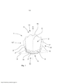
[0077] Aspectos adicionais da presente invenção serão descritos com referência às seguintes figuras esquemáticas. As formas mostram esquematicamente: Figura 1: uma vista em perspectiva de uma válvula-stent de acordo com a invenção, vista de uma extremidade de efluxo; Figuras 2a, 2b: uma vista lateral de uma válvula-stent de acordo com a Figura 1 em uma posição aberta e posição fechada; Figura 3: uma vista em perspectiva de uma válvula-stent alternativa, de acordo com a invenção vista de um lado anterior; Figura 4: o princípio da força sistólica atuando sobre folículo em uma válvula-stent de acordo com a invenção; Figura 5: mostra dimensões circunferenciais da válvula- stent em uma vista de topo.[0077] Additional aspects of the present invention will be described with reference to the following schematic figures. The shapes schematically show: Figure 1: a perspective view of a stent valve according to the invention, seen from an outflow end; Figures 2a, 2b: a side view of a valve-stent according to Figure 1 in an open position and a closed position; Figure 3: a perspective view of an alternative stent valve in accordance with the invention seen from the front; Figure 4: the principle of systolic force acting on a follicle in a valve-stent according to the invention; Figure 5: shows circumferential dimensions of the stent valve in a top view.
[0078] A Figura 1 mostra uma vista de uma válvula-stent 1 vista da extremidade de efluxo 5. A válvula-stent compreende um componente stent 2 e um componente de válvula 3. O componente stent 2 compreende uma extremidade de influxo 4 e uma extremidade de efluxo 5. Entre as extremidades 4 e 5, o componente stent 2 tem uma parede formada por suturas 8 de Nitinol. As suturas 8 são construídos em zigue-zague formando células de diferentes tamanhos. Elementos desacopladores em S 11 conectam algumas células na direção do fluxo A. Os elementos desacopladores 11 têm um diâmetro reduzido em comparação com as suturas 8. O diâmetro reduzido e a forma em S dos elementos desacopladores 11 provêm uma redução da tensão durante alargamento da válvula-stent 1. Com isto provê-se uma melhor conformidade da válvula-stent 1.[0078] Figure 1 shows a view of a valve-
[0079] O componente stent 2 adicionalmente compreende três extensões atriais na extremidade de influxo 4 (sendo que somente duas delas estão mostradas na Figura 1, deixando o terceiro oculto). As extensões atriais 9 são dispostas basicamente perpendicularmente à direção do fluxo A através da válvula-stent 1. Como as extensões atriais 9 se estendem da válvula-stent 1, as extensões atriais 9 contatam a parede do coração atrial quando implantadas, e ajudam na ancoragem e estabilização da válvula-stent 1.[0079] The
[0080] O componente de válvula 3 compreende um folículo 6 afixado aos suportes de tecido 10 através de pontos ao longo de linhas de fixação 7', 7''. O folículo e suportes de tecido são feitos de pericárdio. Os pontos no lado anterior 12 fixam o suporte de tecido 10 ao componente stent 2 ao mesmo tempo em que fixa o folículo 6 aos suportes de tecido 10 e por conseguinte ao componente stent 2. Nas laterais 15', 15'', a linha de fixação 7'está inclinada com respeito ao plano perpendicular ao eixo do fluxo A através da válvula-stent 1. As linhas de fixação 7' nas laterais 15', 15''estão inclinadas, começando da linha de fixação 7'' correndo paralelas ao citado plano. A linha de fixação 7'' no lado anterior 12 é disposta próxima da extremidade de influxo 4 da válvula-stent 1. As linhas de fixação 7' correm da linha de fixação 7'' em um ângulo em direção à extremidade de efluxo 5 da válvula-stent 1. Uma borda livre 14 do folículo 6 contata a parede em um lado posterior 13 do componente stent 2 na posição fechada mostrada (também ver Figura 2b).[0080] The
[0081] O folículo 6 está em uma posição aberta durante a diástole e em repouso. Durante a diástole, o sangue é bombeado do ventrículo esquerdo para a aorta. O sangue sob pressão também atua no folículo 6 e com isto fecha o folículo 6. Por causa a posição inclinada do folículo 6, a força também pressiona o folículo 6 radialmente contra a parede posterior (ver Figura 3). Com a pressão, a válvula-stent 1 é pressionada contra a parede do anel posterior, e, com isto, ajuda a ancorar a válvula-stent 1 no anel mitral na parede ventricular vizinha.[0081]
[0082] As Figuras 2a 2b mostram uma vista lateral da válvula-stent 1. A Figura 2a mostra a válvula-stent na posição aberta e a Figura 2b mostra a válvula-stent na posição fechada.[0082] Figures 2a 2b show a side view of the valve-
[0083] As linhas de fixação 7'correm em um ângulo δ entre 20° e 50° preferivelmente ao redor de 35° com respeito ao plano perpendicular à direção do fluxo A. O ângulo δ pode variar ao longo do comprimento das linhas de fixação 7', começando com um pequeno ângulo δ de 20° na linha de fixação 7'' até um ângulo maior δ de 50° em direção à extremidade de efluxo 5 ou vice-versa.[0083] The attachment lines 7' run at an angle δ between 20° and 50° preferably around 35° with respect to the plane perpendicular to the direction of flow A. The angle δ may vary along the length of the attachment lines 7', starting with a small angle δ of 20° at the attachment line 7'' to a larger angle δ of 50° towards the
[0084] As paredes da extremidade de efluxo 5 do componente stent 2 são alargadas com respeito à direção do fluxo A. As paredes do lado posterior 13 são alargadas com um ângulo ε'de cerca de 20° e as paredes do lado anterior 12 são alargadas com um ângulo ε''de cerca de 18°.The
[0085] O lado anterior 12 tem um comprimento 11 de cerca de 15 a 17 mms, e o lado posterior 13 tem um comprimento 12 maior de cerca de 32 mms. O comprimento da válvula é cerca de 30 a 40 mms, preferivelmente cerca de 34 mms.The
[0086] Na posição aberta mostrada na Figura 2a, a extremidade livre 14 do folículo não contata a parede posterior do componente stent 2. A extremidade livre 14 do folículo 6 é direcionada das linhas de fixação inclinadas 7' para o átrio esquerdo em um estado de tensão aliviada. O sangue pode fluir na direção do fluxo A do ventrículo esquerdo através da válvula-stent 1 para o átrio esquerdo no coração na posição aberta.[0086] In the open position shown in Figure 2a, the
[0087] Na posição fechada mostrada na Figura 2b, a pressão sistólica pressiona a borda livre 14 do folículo contra a parede posterior. A posição fechada do folículo 6 impede o refluxo do sangue do átrio esquerdo para o ventrículo esquerdo. Pressionando o folículo 6 contra a parede posterior, uma força B (ver Figura 3) na direção posterior atua sobre a válvula-stent 1. Com isto, a válvula-stent 1 pressionada na direção posterior, ajudando a ancorar a válvula-stent 1 durante a sístole. A força cinética do ventrículo esquerdo ajuda a ancorar a válvula-stent na posição mitral.[0087] In the closed position shown in Figure 2b, systolic pressure presses the
[0088] A Figura 3 mostra uma válvula-stent 1 alternativa, de acordo com a invenção, vista de um lado anterior 12. A válvula-stent compreende um componente stent 2 e um componente de válvula 3. O componente de válvula 3 é afixado ao componente stent 2 através de suturas ao longo de linhas de fixação 7'. As linhas de fixação inclinadas são dispostas nas laterais 15' 15'' e lado anterior 2. As linhas de fixação inclinadas 7'estão no lado anterior 12 em um ponto de contato 16 formando a chamada "cabeça de sela". A partir da cabeça de sela 16, as linhas de fixação 7' anos inclinam um ângulo Z de cerca de 5o a 10°. O ângulo aumenta em direção à extremidade de efluxo para um ângulo de cerca de 35° nas laterais 15', 15''.[0088] Figure 3 shows an alternative valve-
[0089] A Figura 4 mostra o princípio da força B atuando sobre o folículo 6, e, com isto, sobre a válvula-stent 1 durante a sístole. A força cinética durante a sístole pressiona o folículo contra o lado posterior 13. O folículo 6 pode mudar de posição ao longo do comprimento como mostrado na Figura 3, uma vez que as porções inclinadas são, pelo menos parcialmente, afixadas a tecidos suporte 10.[0089] Figure 4 shows the principle of force B acting on
[0090] Com o folículo inclinado 6, se obtém uma grande coaptação. A coaptação tem no mínimo 10 mm de comprimento. Em válvulas mitrais, onde a pressão é menor que por exemplo, uma prótese trifolicular, sendo que uma grande superfície de coaptação é importante para minimizar o vazamento paravalvular.[0090] With the slanted
[0091] A Figura 5 mostra dimensões circunferenciais da válvula- stent 1 em uma vista de topo. A linha de fixação 7'' tem uma dimensão circunferencial Y no lado anterior 12 de cerca de 30% a 40%. Cada uma das linhas de fixação 7' nas laterais 15', 15'' tem uma dimensão circunferencial β de cerca de 10% a 20%. A borda livre 14 tem uma dimensão circunferencial α no lado posterior 13 de cerca de 30% a 40%. O comprimento das linhas de fixação 7' têm cerca de 25 mms.[0091] Figure 5 shows circumferential dimensions of the valve-
Claims (15)
Applications Claiming Priority (1)
| Application Number | Priority Date | Filing Date | Title |
|---|---|---|---|
| EP14305355.1 | 2014-03-11 |
Publications (1)
| Publication Number | Publication Date |
|---|---|
| BR112016020740B1 true BR112016020740B1 (en) | 2021-09-21 |
Family
ID=
Similar Documents
| Publication | Publication Date | Title |
|---|---|---|
| EP3116445B1 (en) | Cardiac stent-valve | |
| US11337800B2 (en) | Device and method with reduced pacemaker rate in heart valve replacement | |
| US11850146B2 (en) | Prosthetic valve and deployment system | |
| EP3520735B1 (en) | Heart valve prosthesis fixed through interventricular septum | |
| JP4458845B2 (en) | Medical device | |
| JP2020146570A (en) | Structural component for prosthetic mitral valves | |
| ES2243001T3 (en) | EXPANDABLE RING FOR ANULOPLASTY. | |
| US8034102B2 (en) | Aortic annuloplasty ring | |
| JP2016517751A (en) | Prosthetic valve and related devices, systems, and methods | |
| BR112014026724B1 (en) | HEART VALVE PROSTHESIS, DISPENSE DEVICE AND METHOD OF MANUFACTURING A HEART VALVE PROSTHESIS | |
| BR112018010342B1 (en) | ASSEMBLY FOR THE TRICUSPID CHAMBER ORIFICE OF A HUMAN HEART | |
| BR112018007239B1 (en) | MITRAL VALVE ASSEMBLY | |
| CN104334119A (en) | Single-ring cardiac valve support | |
| CA2910751A1 (en) | Heart valve assistive prosthesis | |
| WO2010141847A1 (en) | Flexible commissure structure for attaching valve bioprosthesis | |
| JP2021513376A (en) | Stent mechanisms and methods that assist in juxtaposition and adjustment towards mitigation of innate anatomical structures leaking around the valve | |
| CN115517824A (en) | Repair device for preventing valve backflow | |
| BR112016020740B1 (en) | HEART STENT VALVE AND APPLICATION SYSTEM FOR SUCH VALVE | |
| US20230390052A1 (en) | Prosthetic valve systems, components, and methods | |
| WO2023041705A1 (en) | Prosthetic caval valve | |
| CN113616384A (en) | Valve prosthesis with connecting part |