BR112016019056B1 - method for maintaining the fluid flow pressure in a system at a predefined level, and the mechanism for maintaining the fluid flow pressure in a system at a predefined level - Google Patents
method for maintaining the fluid flow pressure in a system at a predefined level, and the mechanism for maintaining the fluid flow pressure in a system at a predefined level Download PDFInfo
- Publication number
- BR112016019056B1 BR112016019056B1 BR112016019056-4A BR112016019056A BR112016019056B1 BR 112016019056 B1 BR112016019056 B1 BR 112016019056B1 BR 112016019056 A BR112016019056 A BR 112016019056A BR 112016019056 B1 BR112016019056 B1 BR 112016019056B1
- Authority
- BR
- Brazil
- Prior art keywords
- pressure
- needle
- accumulator
- flow
- valve
- Prior art date
Links
Images


Classifications
-
- B—PERFORMING OPERATIONS; TRANSPORTING
- B05—SPRAYING OR ATOMISING IN GENERAL; APPLYING FLUENT MATERIALS TO SURFACES, IN GENERAL
- B05B—SPRAYING APPARATUS; ATOMISING APPARATUS; NOZZLES
- B05B1/00—Nozzles, spray heads or other outlets, with or without auxiliary devices such as valves, heating means
- B05B1/30—Nozzles, spray heads or other outlets, with or without auxiliary devices such as valves, heating means designed to control volume of flow, e.g. with adjustable passages
- B05B1/3033—Nozzles, spray heads or other outlets, with or without auxiliary devices such as valves, heating means designed to control volume of flow, e.g. with adjustable passages the control being effected by relative coaxial longitudinal movement of the controlling element and the spray head
- B05B1/304—Nozzles, spray heads or other outlets, with or without auxiliary devices such as valves, heating means designed to control volume of flow, e.g. with adjustable passages the control being effected by relative coaxial longitudinal movement of the controlling element and the spray head the controlling element being a lift valve
- B05B1/3046—Nozzles, spray heads or other outlets, with or without auxiliary devices such as valves, heating means designed to control volume of flow, e.g. with adjustable passages the control being effected by relative coaxial longitudinal movement of the controlling element and the spray head the controlling element being a lift valve the valve element, e.g. a needle, co-operating with a valve seat located downstream of the valve element and its actuating means, generally in the proximity of the outlet orifice
-
- G—PHYSICS
- G05—CONTROLLING; REGULATING
- G05D—SYSTEMS FOR CONTROLLING OR REGULATING NON-ELECTRIC VARIABLES
- G05D16/00—Control of fluid pressure
- G05D16/14—Control of fluid pressure with auxiliary non-electric power
- G05D16/16—Control of fluid pressure with auxiliary non-electric power derived from the controlled fluid
-
- F—MECHANICAL ENGINEERING; LIGHTING; HEATING; WEAPONS; BLASTING
- F16—ENGINEERING ELEMENTS AND UNITS; GENERAL MEASURES FOR PRODUCING AND MAINTAINING EFFECTIVE FUNCTIONING OF MACHINES OR INSTALLATIONS; THERMAL INSULATION IN GENERAL
- F16K—VALVES; TAPS; COCKS; ACTUATING-FLOATS; DEVICES FOR VENTING OR AERATING
- F16K31/00—Actuating devices; Operating means; Releasing devices
-
- B—PERFORMING OPERATIONS; TRANSPORTING
- B05—SPRAYING OR ATOMISING IN GENERAL; APPLYING FLUENT MATERIALS TO SURFACES, IN GENERAL
- B05B—SPRAYING APPARATUS; ATOMISING APPARATUS; NOZZLES
- B05B1/00—Nozzles, spray heads or other outlets, with or without auxiliary devices such as valves, heating means
- B05B1/30—Nozzles, spray heads or other outlets, with or without auxiliary devices such as valves, heating means designed to control volume of flow, e.g. with adjustable passages
- B05B1/32—Nozzles, spray heads or other outlets, with or without auxiliary devices such as valves, heating means designed to control volume of flow, e.g. with adjustable passages in which a valve member forms part of the outlet opening
- B05B1/323—Nozzles, spray heads or other outlets, with or without auxiliary devices such as valves, heating means designed to control volume of flow, e.g. with adjustable passages in which a valve member forms part of the outlet opening the valve member being actuated by the pressure of the fluid to be sprayed
-
- F—MECHANICAL ENGINEERING; LIGHTING; HEATING; WEAPONS; BLASTING
- F03—MACHINES OR ENGINES FOR LIQUIDS; WIND, SPRING, OR WEIGHT MOTORS; PRODUCING MECHANICAL POWER OR A REACTIVE PROPULSIVE THRUST, NOT OTHERWISE PROVIDED FOR
- F03B—MACHINES OR ENGINES FOR LIQUIDS
- F03B1/00—Engines of impulse type, i.e. turbines with jets of high-velocity liquid impinging on blades or like rotors, e.g. Pelton wheels; Parts or details peculiar thereto
- F03B1/04—Nozzles; Nozzle-carrying members
-
- F—MECHANICAL ENGINEERING; LIGHTING; HEATING; WEAPONS; BLASTING
- F16—ENGINEERING ELEMENTS AND UNITS; GENERAL MEASURES FOR PRODUCING AND MAINTAINING EFFECTIVE FUNCTIONING OF MACHINES OR INSTALLATIONS; THERMAL INSULATION IN GENERAL
- F16K—VALVES; TAPS; COCKS; ACTUATING-FLOATS; DEVICES FOR VENTING OR AERATING
- F16K1/00—Lift valves or globe valves, i.e. cut-off apparatus with closure members having at least a component of their opening and closing motion perpendicular to the closing faces
- F16K1/32—Details
- F16K1/34—Cutting-off parts, e.g. valve members, seats
- F16K1/36—Valve members
- F16K1/38—Valve members of conical shape
- F16K1/385—Valve members of conical shape contacting in the closed position, over a substantial axial length, a seat surface having the same inclination
-
- F—MECHANICAL ENGINEERING; LIGHTING; HEATING; WEAPONS; BLASTING
- F16—ENGINEERING ELEMENTS AND UNITS; GENERAL MEASURES FOR PRODUCING AND MAINTAINING EFFECTIVE FUNCTIONING OF MACHINES OR INSTALLATIONS; THERMAL INSULATION IN GENERAL
- F16K—VALVES; TAPS; COCKS; ACTUATING-FLOATS; DEVICES FOR VENTING OR AERATING
- F16K17/00—Safety valves; Equalising valves, e.g. pressure relief valves
- F16K17/02—Safety valves; Equalising valves, e.g. pressure relief valves opening on surplus pressure on one side; closing on insufficient pressure on one side
- F16K17/04—Safety valves; Equalising valves, e.g. pressure relief valves opening on surplus pressure on one side; closing on insufficient pressure on one side spring-loaded
-
- F—MECHANICAL ENGINEERING; LIGHTING; HEATING; WEAPONS; BLASTING
- F16—ENGINEERING ELEMENTS AND UNITS; GENERAL MEASURES FOR PRODUCING AND MAINTAINING EFFECTIVE FUNCTIONING OF MACHINES OR INSTALLATIONS; THERMAL INSULATION IN GENERAL
- F16K—VALVES; TAPS; COCKS; ACTUATING-FLOATS; DEVICES FOR VENTING OR AERATING
- F16K31/00—Actuating devices; Operating means; Releasing devices
- F16K31/12—Actuating devices; Operating means; Releasing devices actuated by fluid
- F16K31/126—Actuating devices; Operating means; Releasing devices actuated by fluid the fluid acting on a diaphragm, bellows, or the like
- F16K31/1266—Actuating devices; Operating means; Releasing devices actuated by fluid the fluid acting on a diaphragm, bellows, or the like one side of the diaphragm being acted upon by the circulating fluid
-
- G—PHYSICS
- G05—CONTROLLING; REGULATING
- G05D—SYSTEMS FOR CONTROLLING OR REGULATING NON-ELECTRIC VARIABLES
- G05D16/00—Control of fluid pressure
-
- G—PHYSICS
- G05—CONTROLLING; REGULATING
- G05D—SYSTEMS FOR CONTROLLING OR REGULATING NON-ELECTRIC VARIABLES
- G05D16/00—Control of fluid pressure
- G05D16/04—Control of fluid pressure without auxiliary power
- G05D16/06—Control of fluid pressure without auxiliary power the sensing element being a flexible membrane, yielding to pressure, e.g. diaphragm, bellows, capsule
- G05D16/063—Control of fluid pressure without auxiliary power the sensing element being a flexible membrane, yielding to pressure, e.g. diaphragm, bellows, capsule the sensing element being a membrane
-
- B—PERFORMING OPERATIONS; TRANSPORTING
- B01—PHYSICAL OR CHEMICAL PROCESSES OR APPARATUS IN GENERAL
- B01D—SEPARATION
- B01D2311/00—Details relating to membrane separation process operations and control
- B01D2311/14—Pressure control
-
- G—PHYSICS
- G05—CONTROLLING; REGULATING
- G05D—SYSTEMS FOR CONTROLLING OR REGULATING NON-ELECTRIC VARIABLES
- G05D16/00—Control of fluid pressure
- G05D16/04—Control of fluid pressure without auxiliary power
- G05D16/06—Control of fluid pressure without auxiliary power the sensing element being a flexible membrane, yielding to pressure, e.g. diaphragm, bellows, capsule
- G05D16/063—Control of fluid pressure without auxiliary power the sensing element being a flexible membrane, yielding to pressure, e.g. diaphragm, bellows, capsule the sensing element being a membrane
- G05D16/0644—Control of fluid pressure without auxiliary power the sensing element being a flexible membrane, yielding to pressure, e.g. diaphragm, bellows, capsule the sensing element being a membrane the membrane acting directly on the obturator
-
- Y—GENERAL TAGGING OF NEW TECHNOLOGICAL DEVELOPMENTS; GENERAL TAGGING OF CROSS-SECTIONAL TECHNOLOGIES SPANNING OVER SEVERAL SECTIONS OF THE IPC; TECHNICAL SUBJECTS COVERED BY FORMER USPC CROSS-REFERENCE ART COLLECTIONS [XRACs] AND DIGESTS
- Y02—TECHNOLOGIES OR APPLICATIONS FOR MITIGATION OR ADAPTATION AGAINST CLIMATE CHANGE
- Y02E—REDUCTION OF GREENHOUSE GAS [GHG] EMISSIONS, RELATED TO ENERGY GENERATION, TRANSMISSION OR DISTRIBUTION
- Y02E10/00—Energy generation through renewable energy sources
- Y02E10/20—Hydro energy
-
- Y—GENERAL TAGGING OF NEW TECHNOLOGICAL DEVELOPMENTS; GENERAL TAGGING OF CROSS-SECTIONAL TECHNOLOGIES SPANNING OVER SEVERAL SECTIONS OF THE IPC; TECHNICAL SUBJECTS COVERED BY FORMER USPC CROSS-REFERENCE ART COLLECTIONS [XRACs] AND DIGESTS
- Y02—TECHNOLOGIES OR APPLICATIONS FOR MITIGATION OR ADAPTATION AGAINST CLIMATE CHANGE
- Y02E—REDUCTION OF GREENHOUSE GAS [GHG] EMISSIONS, RELATED TO ENERGY GENERATION, TRANSMISSION OR DISTRIBUTION
- Y02E10/00—Energy generation through renewable energy sources
- Y02E10/30—Energy from the sea, e.g. using wave energy or salinity gradient
-
- Y—GENERAL TAGGING OF NEW TECHNOLOGICAL DEVELOPMENTS; GENERAL TAGGING OF CROSS-SECTIONAL TECHNOLOGIES SPANNING OVER SEVERAL SECTIONS OF THE IPC; TECHNICAL SUBJECTS COVERED BY FORMER USPC CROSS-REFERENCE ART COLLECTIONS [XRACs] AND DIGESTS
- Y10—TECHNICAL SUBJECTS COVERED BY FORMER USPC
- Y10T—TECHNICAL SUBJECTS COVERED BY FORMER US CLASSIFICATION
- Y10T137/00—Fluid handling
- Y10T137/0318—Processes
- Y10T137/0324—With control of flow by a condition or characteristic of a fluid
- Y10T137/0357—For producing uniform flow
-
- Y—GENERAL TAGGING OF NEW TECHNOLOGICAL DEVELOPMENTS; GENERAL TAGGING OF CROSS-SECTIONAL TECHNOLOGIES SPANNING OVER SEVERAL SECTIONS OF THE IPC; TECHNICAL SUBJECTS COVERED BY FORMER USPC CROSS-REFERENCE ART COLLECTIONS [XRACs] AND DIGESTS
- Y10—TECHNICAL SUBJECTS COVERED BY FORMER USPC
- Y10T—TECHNICAL SUBJECTS COVERED BY FORMER US CLASSIFICATION
- Y10T137/00—Fluid handling
- Y10T137/0318—Processes
- Y10T137/0396—Involving pressure control
-
- Y—GENERAL TAGGING OF NEW TECHNOLOGICAL DEVELOPMENTS; GENERAL TAGGING OF CROSS-SECTIONAL TECHNOLOGIES SPANNING OVER SEVERAL SECTIONS OF THE IPC; TECHNICAL SUBJECTS COVERED BY FORMER USPC CROSS-REFERENCE ART COLLECTIONS [XRACs] AND DIGESTS
- Y10—TECHNICAL SUBJECTS COVERED BY FORMER USPC
- Y10T—TECHNICAL SUBJECTS COVERED BY FORMER US CLASSIFICATION
- Y10T137/00—Fluid handling
- Y10T137/7722—Line condition change responsive valves
- Y10T137/7781—With separate connected fluid reactor surface
- Y10T137/7835—Valve seating in direction of flow
- Y10T137/7836—Flexible diaphragm or bellows reactor
Landscapes
- Engineering & Computer Science (AREA)
- General Engineering & Computer Science (AREA)
- Mechanical Engineering (AREA)
- Physics & Mathematics (AREA)
- Fluid Mechanics (AREA)
- General Physics & Mathematics (AREA)
- Automation & Control Theory (AREA)
- Chemical & Material Sciences (AREA)
- Combustion & Propulsion (AREA)
- Power Engineering (AREA)
- Control Of Fluid Pressure (AREA)
- Hydraulic Turbines (AREA)
- Lift Valve (AREA)
- Control Of Turbines (AREA)
- Other Liquid Machine Or Engine Such As Wave Power Use (AREA)
- Separation Using Semi-Permeable Membranes (AREA)
- Safety Valves (AREA)
- Jet Pumps And Other Pumps (AREA)
Abstract
MÉTODO PARA MANTER A PRESSÃO DE ESCOAMENTO DE FLUIDOS EM UM SISTEMA A UM NÍVEL PREDEFINIDO, E, MECANISMO PARA MANTER A PRESSÃO DE ESCOAMENTO DE FLUIDOS EM UM SISTEMA A UM NÍVEL PREDEFINIDO Esta invenção se refere a um método e mecanismo para manter a pressão de escoamento de fluidos em um sistema a um nível predefinido, quase constante. Uma aplicação é uma válvula de bocal para turbina de impulso (1), a qual mantém automaticamente a pressão do sistema essencialmente constante, de modo a que ele não dependa da variação ocasional da entrada de vazão bombeada, resultando em que também o jato a partir do bocal permaneça constante e sua energia cinética ótima. Os bocais anteriormente conhecidos não mantêm independentemente a pressão do sistema,quando a entrada de vazão varia. A válvula de bocal (1) compreende um corpo cilíndrico (2) e um canal de entrada (3) e a saída de vazão é disposta através de um canal do bocal (8) situado na outra extremidade do corpo (2). No interior do corpo (2) está uma agulha (4), cuja cabeça cônica pode oscilar dentro do canal (8). A haste da agulha (4) é guiada por um elemento deslizante (11). À outra extremidade do corpo (2) está unido um acumulador de pressão com diafragma (6), de (...).METHOD FOR MAINTAINING FLUID FLOW PRESSURE IN A SYSTEM AT A PRESET LEVEL, AND MECHANISM TO MAINTAIN FLUID FLOW PRESSURE IN A SYSTEM AT A PRESET LEVEL This invention relates to a method and mechanism for maintaining flow pressure of fluids in a system at a predefined, almost constant level. One application is a nozzle valve for impulse turbine (1), which automatically maintains the system pressure essentially constant, so that it does not depend on the occasional variation of the pumped flow inlet, resulting in the jet also starting from the nozzle remains constant and its kinetic energy is optimal. The previously known nozzles do not independently maintain the system pressure when the flow inlet varies. The nozzle valve (1) comprises a cylindrical body (2) and an inlet channel (3) and the flow outlet is arranged through a nozzle channel (8) located at the other end of the body (2). Inside the body (2) is a needle (4), whose conical head can oscillate within the channel (8). The needle rod (4) is guided by a sliding element (11). A pressure accumulator with diaphragm (6), of (...) is attached to the other end of the body (2).
Description
[001] Esta invenção se refere a um método, de acordo com o preâmbulo da reivindicação 1, para manter a pressão de escoamento de fluidos em um sistema a um nível predefinido, quase constante, não dependendo da variação periódica da vazão mássica bombeada para seu interior.[001] This invention relates to a method, according to the preamble of claim 1, to maintain the fluid flow pressure in a system at a predefined level, almost constant, not depending on the periodic variation of the mass flow pumped to your system. interior.
[002] A invenção se refere também a um mecanismo aplicando o método, cujas características típicas são definidas no preâmbulo da reivindicação 5.[002] The invention also relates to a mechanism applying the method, the typical characteristics of which are defined in the preamble of claim 5.
[003] Uma válvula de bocal, como uma parte do mecanismo que aplica a invenção, converte a vazão em um jato de alta pressão, o qual é direcionado para conchas de turbina de impulso. A invenção é especialmente adequada para usar com sistemas de energia das ondas e de osmose inversa.[003] A nozzle valve, as a part of the mechanism that applies the invention, converts the flow into a high pressure jet, which is directed to impulse turbine shells. The invention is especially suitable for use with wave energy and reverse osmosis systems.
[004] A publicação WO 2004099658 A1 se refere a uma válvula de bocal para turbina, cuja abertura é regulada por um motor de engrenagem elétrica e seu rápido encerramento é alcançado através da utilização de um acumulador de pressão.[004] The publication WO 2004099658 A1 refers to a nozzle valve for turbine, the opening of which is regulated by an electric gear motor and its fast closing is achieved through the use of a pressure accumulator.
[005] As publicações US 58322944 e WO 9813633 A1 se relacionam com uma válvula de bocal para turbina, cuja abertura é regulada com um motor de engrenagem elétrica. No último caso, o rápido encerramento da válvula é levado a cabo usando um acumulador de pressão.[005] Publications US 58322944 and WO 9813633 A1 relate to a nozzle valve for turbine, the opening of which is regulated with an electric gear motor. In the latter case, the rapid closing of the valve is carried out using a pressure accumulator.
[006] É bem sabido que a água pode ser bombeada através da utilização de energia das ondas. A vazão mássica bombeada varia ocasionalmente, dependendo das condições do vento. Em contraste com as centrais hidrelétricas convencionais, a água que é bombeada com energia das ondas não tem potencial energético e a resultante pressão constante. Por esta razão, a pressão de vazão deve ser disposta especificamente. Uma solução típica é uma válvula de estrangulamento instalada na saída de vazão do sistema, causando a subida da pressão. Uma tal válvula pode ser uma válvula de bocal para turbina de impulso, a qual direciona ao mesmo tempo um jato para as conchas da turbina. Fig.1a.[006] It is well known that water can be pumped through the use of wave energy. The mass flow pumped varies occasionally, depending on wind conditions. In contrast to conventional hydroelectric power plants, water that is pumped with wave energy has no energy potential and the resulting constant pressure. For this reason, the flow pressure must be specifically arranged. A typical solution is a throttle valve installed at the flow outlet of the system, causing the pressure to rise. Such a valve can be a nozzle valve for impulse turbine, which at the same time directs a jet towards the turbine shells. Fig.1a.
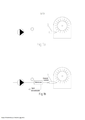
[007] Uma válvula de bocal anteriormente conhecida, a qual se parece com a invenção e é usada com uma turbina Pelton, é descrita nas figuras Fig.2a e Fig.2b. Este tipo de válvulas é usado quando a pressão de vazão deriva da diferença de altura entre os níveis de água, em cujo caso a pressão hidrostática permanece constante e não depende da quantidade de vazão mássica jorrando através do bocal. A área de corte transversal da boca do bocal pode ser ajustada movendo uma agulha cônica em seu interior e, devido a isto, varia a vazão mássica através dela, mas a velocidade do jato permanece inalterada, devido à pressão constante. A velocidade do jato é: v = Cv • V(2gH), em que H (cabeça) é a altura da conduta de água (m), Cv é o coeficiente do bocal ~ 0,98. Esta equação significa que a velocidade do jato depende somente da pressão, a qual por sua vez depende da altura da conduta.[007] A previously known nozzle valve, which looks like the invention and is used with a Pelton turbine, is described in figures Fig.2a and Fig.2b. This type of valve is used when the flow pressure derives from the height difference between the water levels, in which case the hydrostatic pressure remains constant and does not depend on the amount of mass flow flowing through the nozzle. The cross-sectional area of the mouth of the nozzle can be adjusted by moving a tapered needle inside and, due to this, the mass flow through it varies, but the jet velocity remains unchanged, due to the constant pressure. The jet speed is: v = Cv • V (2gH), where H (head) is the height of the water duct (m), Cv is the nozzle coefficient ~ 0.98. This equation means that the velocity of the jet depends only on the pressure, which in turn depends on the height of the duct.
[008] Em centrais elétricas pequenas a agulha é normalmente ajustada com mecanismos de comando manual, Fig.2a, e nos sistemas maiores, acima de 100 kW, através de mecanismos de regulação, nos quais o movimento da agulha é conseguido com óleo pressurizado de servo motor, Fig.2b. A finalidade destes mecanismos é regular a vazão mássica entrando no bocal, de modo a que a vazão corresponda à carga da turbina. A energia cinética do jato Ev = (mv2)/2 vai variando de acordo com as variações da vazão mássica e a potência da turbina vai se alterar em conformidade. Portanto, a velocidade do jato depende somente da pressão causada pela quantidade de água retida.[008] In small power plants the needle is normally adjusted with manual control mechanisms, Fig.2a, and in larger systems, above 100 kW, through regulation mechanisms, in which the needle movement is achieved with pressurized oil of servo motor, Fig.2b. The purpose of these mechanisms is to regulate the mass flow entering the nozzle, so that the flow corresponds to the turbine load. The kinetic energy of the Ev = (mv2) / 2 jet will vary according to the mass flow variations and the turbine power will change accordingly. Therefore, the speed of the jet depends only on the pressure caused by the amount of water retained.
[009] É óbvio que não faz sentido produzir energia com água, a qual tenha sido pressurizada com bombas elétricas ou a diesel. É por isso que as válvulas mencionadas acima têm sido destinadas para funcionar com turbinas, nas centrais elétricas em que a água tem energia potencial. Elas não são destinadas nem adequadas quando a válvula de bocal em si tem de manter a pressão constante em um sistema, para o interior do qual a vazão mássica bombeada vai variando ocasionalmente.[009] It is obvious that it does not make sense to produce energy with water, which has been pressurized with electric or diesel pumps. That is why the valves mentioned above have been designed to work with turbines, in power plants where water has potential energy. They are neither intended nor suitable when the nozzle valve itself has to maintain constant pressure in a system, into which the mass flow pumped varies from time to time.
[0010] Em contraste com estas, o princípio de funcionamento da válvula de bocal, de acordo com a invenção, é apenas manter independentemente a pressão do sistema constante, não dependendo das variações de vazão mássica. Como uma sua utilização preferida é utilizar a quantidade de energia, a qual a água que é bombeada através de energia das ondas e também o material rejeitado da osmose inversa contêm.[0010] In contrast to these, the working principle of the nozzle valve, according to the invention, is only to maintain the system pressure constant independently, not depending on the mass flow variations. As a preferred use it is to use the amount of energy, which the water that is pumped through wave energy and also the rejected material from reverse osmosis contain.
[0011] A velocidade do jato permanece constante se a pressão da água permanecer constante. Por exemplo, a uma pressão de 50 bar na equação acima corresponde uma conduta de água com 500 metros de altura.[0011] The jet speed remains constant if the water pressure remains constant. For example, a pressure of 50 bar in the equation above corresponds to a water pipe 500 meters high.
[0012] Porque a velocidade do jato depende somente da pressão, então quando a pressão permanece constante a potência da turbina Pmax = m • p, em que m é a vazão mássica e p a pressão, se altera na proporção direta à alteração da vazão mássica. Está claro que se tanto a vazão mássica como a pressão descaírem simultaneamente, como é o caso com um bocal de boca constante, então a potência descai drasticamente.[0012] Because the jet speed depends only on the pressure, then when the pressure remains constant the turbine power Pmax = m • p, where m is the mass flow rate and p the pressure, changes in direct proportion to the change in the mass flow rate. It is clear that if both the mass flow and the pressure drop simultaneously, as is the case with a nozzle with a constant mouth, then the power drops dramatically.
[0013] A variação simultânea do volume e pressão de vazão é também problemática em relação ao funcionamento de um sistema de osmose inversa, porque a pressão da água salgada dentro dos módulos de osmose inversa deve ser mais elevada do que a pressão osmótica da água, a qual no caso de água do mar é superior a 36 bar. Portanto, o constante estrangulamento vulgarmente usado nestes sistemas é somente aplicável quando a entrada de vazão bombeada é constante. No entanto, com a energia das ondas isso nunca é o caso. Em um sistema de osmose inversa, o dispositivo de estrangulamento é instalado no tubo para material rejeitado. O material rejeitado é a concentração de sal, a qual escoa para fora a partir do módulo e o bocal de estrangulamento da vazão forma um jato, direcionando-o para a turbina, Fig.1b.[0013] The simultaneous variation of the volume and flow pressure is also problematic in relation to the operation of a reverse osmosis system, because the pressure of the salt water inside the reverse osmosis modules must be higher than the osmotic pressure of the water, which in the case of sea water is greater than 36 bar. Therefore, the constant strangulation commonly used in these systems is only applicable when the pumped flow input is constant. However, with wave energy this is never the case. In a reverse osmosis system, the throttling device is installed in the tube for discarded material. The rejected material is the salt concentration, which flows out from the module and the flow throttling nozzle forms a jet, directing it towards the turbine, Fig.1b.
[0014] O material rejeitado, o qual está escoando para fora a partir do módulo de osmose inversa, pode conter 70-90% da energia de bombeamento inicial.[0014] The discarded material, which is seeping out from the reverse osmosis module, can contain 70-90% of the initial pumping energy.
[0015] O dispositivo que estrangula e mantém a pressão de escoamento da osmose inversa pode por exemplo ser uma válvula de alívio de pressão. No entanto, então um problema essencial é que, depois do estrangulamento, se perde a energia que o material rejeitado tem contida, não podendo ser utilizada na turbina. A pressão de abertura em uma válvula de alívio de pressão operando mecanicamente é de cerca do dobro de sua pressão de encerramento, o que cria um problema em sistemas de osmose inversa.[0015] The device that strangles and maintains the flow pressure of reverse osmosis can for example be a pressure relief valve. However, then an essential problem is that, after strangulation, the energy that the rejected material has contained is lost and cannot be used in the turbine. The opening pressure in a mechanically operated pressure relief valve is about twice its closing pressure, which creates a problem in reverse osmosis systems.
[0016] Pelas razões descritas acima, é essencial que a pressão dentro da válvula de estrangulamento de vazão permaneça constante também em casos em que a entrada de vazão esteja ocasionalmente variando.[0016] For the reasons described above, it is essential that the pressure inside the flow throttle valve remains constant also in cases where the flow inlet is occasionally varying.
[0017] A finalidade da invenção é criar um método e mecanismo nos quais uma válvula de bocal mantenha a pressão de escoamento de fluidos em um sistema a um nível predefinido e quase constante, não dependendo das variações periódicas da vazão mássica bombeada para seu interior. A mesma válvula de bocal converte a vazão em um jato de alta pressão, o direcionando por exemplo para conchas da turbina de impulso.[0017] The purpose of the invention is to create a method and mechanism in which a nozzle valve maintains the fluid flow pressure in a system at a predefined and almost constant level, not depending on the periodic variations of the mass flow pumped into it. The same nozzle valve converts the flow into a high pressure jet, directing it, for example, to impeller turbine shells.
[0018] A finalidade é alcançada com o método, de acordo com a invenção, caracterizado na reivindicação 1 e com o mecanismo, de acordo com a invenção, caracterizado na reivindicação 5.[0018] The purpose is achieved with the method, according to the invention, characterized in claim 1 and with the mechanism, according to the invention, characterized in claim 5.
[0019] A invenção é especialmente adequada para ser usada para manter a pressão do sistema de osmose inversa e utilizando a pressão de seu material rejeitado, através da utilização de uma turbina Pelton. Então a produção de água doce e, através da força do material rejeitado operando a turbina de impulso, vai ter uma ótima eficiência.[0019] The invention is especially suitable to be used to maintain the pressure of the reverse osmosis system and using the pressure of its rejected material, through the use of a Pelton turbine. So the production of fresh water and, through the force of the discarded material operating the impulse turbine, will have an excellent efficiency.
[0020] O método e mecanismo, de acordo com a invenção, são descritos mais detalhadamente em seguida, com referência às figuras Fig.1a, Fig.3a, e Fig.3b.[0020] The method and mechanism, according to the invention, are described in more detail below, with reference to the figures Fig.1a, Fig.3a, and Fig.3b.
[0021] A válvula de bocal 1 compreende um corpo de preferência cilíndrico 2, oco e longo, o qual pode ser montado com diversas peças e na outra extremidade do qual, na direção do eixo do corpo 2 está um canal do bocal 8, o qual é de preferência cônico, possuindo corte transversal circular e através do qual a saída de vazão é disposta. A entrada de vazão para o corpo 2 acontece através de um canal 3 na parede do corpo.[0021] The nozzle valve 1 comprises a preferably
[0022] Por uma questão de clareza, essa extremidade do corpo 2 em que o canal 8 está situado é referida daqui por diante como a parte inferior do corpo 2.[0022] For the sake of clarity, that end of
[0023] O canal 8 é aberto e fechado com um movimento oscilante da agulha 4 no interior do corpo 2. A agulha é formada por uma haste essencialmente cilíndrica e uma cabeça cônica, a qual abre e fecha gradualmente o canal 8 alterando sua área de escoamento de corte transversal quando a está movendo.[0023] Channel 8 is opened and closed with an oscillating movement of the
[0024] Quando o canal 8 está fechado, a cabeça da agulha 4 tem um pequeno espaço até à boca do canal 8. Quando o canal 8 está fechado, ele não tem que ser totalmente vedante, é suficiente que o escoamento através dele esteja essencialmente bloqueado. A extremidade superior do corpo 2, a qual está oposta ao canal 8, possui um acumulador de pressão 6 unido a ela, diretamente ou com um tubo intermédio 14, de uma forma tal que a entrada de vazão para o bloco 2 pode também conseguir passar por baixo do disco da válvula 10 do acumulador 6 através do canal 9, o qual está formado entre o corpo 2 e o acumulador 6 e a agulha 4 pode se mover no interior do canal 9 oscilando axialmente. Um elemento deslizante 11 está montado no interior do corpo 2 para guiar a haste da agulha 4. No exterior do elemento deslizante 11 existem sulcos ou canais 13 na parede do corpo 2, através dos quais a corrente de vazão entrando para o interior do corpo 2 através do canal 3 pode passar para o outro lado do elemento deslizante 11 e continuar para o canal 9, e consequentemente por baixo do disco da válvula 10, o qual fecha o acumulador pré-pressurizado 6. Fig.3b. É também possível que o sulco ou canal 13 esteja dentro da haste da agulha 4.[0024] When channel 8 is closed, the
[0025] No início, quando não existe vazão, a cabeça da agulha 4 fecha o canal 8 e a agulha 4 fica então em sua posição mais baixa e o disco 10 fica suportado pelo corpo do acumulador 6. Fig.3a. Nesta situação, a extremidade da haste da agulha 4 é pressionada contra o disco 10 por meio de uma mola de compressão 5. A mola 5 está esticada e sua extremidade inferior é essencialmente suportada pelo elemento deslizante 11 ou pelo corpo 2 e sua extremidade superior por uma placa 12 montada sobre a haste da agulha 4 ou através de um alargamento na haste.[0025] At the beginning, when there is no flow, the
[0026] Quando uma bomba hidráulica começa a bombear a entrada de vazão para o sistema, a pressão de vazão sobe dentro do corpo 2, porque a vazão não é capaz de sair através do canal 8, enquanto a agulha 4 o está encerrando. A agulha 4 também não pode se mover porque sua extremidade superior, por meio da mola 5, está comprimida contra o disco da válvula 10, o qual fecha o acumulador 6. Por esta razão, a pressão de vazão aumenta até exceder a pressão pré- pressurizada p0 no interior do acumulador 6 e então o disco 10 começa a subir por causa da força de elevação que o está afetando. Esta força de elevação é a soma da força da mola Fs e da força que a pressão de vazão p1 causa sobre a agulha 4. A força da mola segura a extremidade da haste da agulha 4 todo o tempo, tocando essencialmente o disco 10. Porque a pressão p1 é elevada, é possível que ela possa entrar por entre a extremidade da haste da agulha e o disco 10. Nesse caso, a pressão p1 iria tentar pressionar a agulha no sentido descente e, por causa disto, a força da mola tem que ser maior em todas as situações do que esta força de pressão no sentido descente.[0026] When a hydraulic pump starts to pump the flow inlet to the system, the flow pressure rises inside the
[0027] À medida que a cabeça da agulha cônica 4 sobe com o disco 10, o canal de saída de vazão 8 se abre e sua área de escoamento de corte transversal aumenta de forma correspondente. Fig.3b. O canal 8 se abre somente o suficiente para que o volume de vazão através dele corresponda à pressão p2. A pressão de gás p2 dentro do acumulador de pressão com diafragma 6 e a pressão de entrada de vazão p1 dentro da válvula 1 são essencialmente iguais em todas as situações operacionais de escoamento.[0027] As the
[0028] Quanto maior for o volume de gás que o acumulador 6 tem, mais pequena é a diferença entre a p2 e a pressão pré-pressurizada p0 no interior do acumulador 6. Isto é por que então a alteração relativa do volume de gás dentro do acumulador 6, devido à subida da agulha 4, permanece pequena. A alteração máxima do volume operacional deveria ser menor do que 16%, vantajosamente menor do que 9% do volume do acumulador, prestes a atingir o nível de pressão operacional do acumulador.[0028] The greater the volume of gas that accumulator 6 has, the smaller the difference between p2 and the pre-pressurized pressure p0 inside accumulator 6. This is why then the relative change in the volume of gas inside accumulator 6, due to the rise of
[0029] A razão da pressão operacional máxima p2 para a pressão de pré-carga de gás p0 nunca pode ser mais elevada do que a razão da pressão de projeto do acumulador, dada pelo fabricante, normalmente 4:1.[0029] The ratio of the maximum operating pressure p2 to the pre-charge pressure of gas p0 can never be higher than the ratio of the design pressure of the accumulator, given by the manufacturer, normally 4: 1.
[0030] A subida da pressão de p0 para p2 dentro do acumulador (6) é inversamente proporcional à alteração de seu volume de gás, devido à subida da agulha (4). A pressão operacional máxima p2 pode ser escolhida para o nível desejado através da seleção da p0, do volume do acumulador, do ângulo do cone da cabeça da agulha (4) e do corte transversal da boca do canal (8), de acordo com o máximo volume de vazão operacional.[0030] The increase in pressure from p0 to p2 inside the accumulator (6) is inversely proportional to the change in its gas volume, due to the rise of the needle (4). The maximum operating pressure p2 can be chosen to the desired level by selecting the p0, the volume of the accumulator, the angle of the needle head cone (4) and the cross section of the channel mouth (8), according to the maximum volume of operational flow.
[0031] Razão vantajosa da pressão operacional devido à subida da agulha (4): p2/p0 < 1,1.[0031] Advantageous ratio of the operating pressure due to the rise of the needle (4): p2 / p0 <1.1.
[0032] Desta forma, a pressão de vazão p1 permanece quase constante, mesmo apesar do volume de vazão ocasionalmente variar, e como resultado disto, também a pressão em todo o sistema permanece essencialmente constante. Quando a entrada de vazão para, a válvula 1 mantém a pressão do sistema no nível p0. No entanto, é benéfico para um módulo de osmose inversa que não fique qualquer água salgada altamente concentrada em seu interior e, assim o canal 8 pode ser deixado ligeiramente aberto. Quando usado com um sistema de osmose inversa, a pressão inicial p0 dentro do acumulador 6 é escolhida mais elevada do que a pressão osmótica da água salina a ser tratada. A pressão p0 é fixada essencialmente para o nível no qual se deseja que esteja a pressão operacional em todo o sistema e no qual o jato, providenciado pela válvula 1, começa.[0032] In this way, the flow pressure p1 remains almost constant, even though the flow volume occasionally varies, and as a result, the pressure in the entire system also remains essentially constant. When the flow inlet stops, valve 1 maintains the system pressure at the p0 level. However, it is beneficial for a reverse osmosis module that does not have any highly concentrated salt water in it, so that channel 8 can be left slightly open. When used with a reverse osmosis system, the initial pressure p0 inside the accumulator 6 is chosen higher than the osmotic pressure of the saline water to be treated. The pressure p0 is essentially fixed to the level at which the operating pressure is desired throughout the system and at which the jet, provided by valve 1, begins.
[0033] A força da mola 5 é definida de acordo com a área circular de corte transversal da boca do canal 8 de saída de vazão, a pressão pré-pressurizada inicial de gás p0 dentro do acumulador 6 e o movimento operacional máximo da agulha 4. A força da mola Fs deve ser a maior nas seguintes equações: a) Fs = p2 • A7, quando a agulha 4 está em sua posição operacional mais elevada b) Fs = p0 • A7, quando a agulha 4 está encerrando o canal 8.[0033] The force of the spring 5 is defined according to the circular cross-sectional area of the mouth of the flow outlet channel 8, the initial pre-pressurized pressure of gas p0 inside the accumulator 6 and the maximum operational movement of the
[0034] A A7 é a área de corte transversal da cabeça da agulha cônica 4 mesmo na boca do canal 8, perpendicular a seu eixo longitudinal no momento atual de funcionamento. Porque na prática a pressão de vazão p1 pode entrar por entre a extremidade da haste da agulha 4 e o disco da válvula 10, assim de modo a que a agulha 4 suba com o disco da válvula 10, a força da mola elevando a agulha 4 deve ser maior do que a força causada pela pressão p1 a qual a está pressionando no sentido descendente.[0034] A7 is the cross-sectional area of the
[0035] No entanto, a força de mola necessária é relativamente pequena e somente uma fração, em comparação com as forças de mola das válvulas de alívio de pressão convencionais. Na solução, de acordo com a invenção, o movimento da agulha 4 é suave e sem atritos, e ela se move rapidamente como resultado mesmo da mais pequena tentativa para alterar a pressão p1, a mantendo assim essencialmente constante.[0035] However, the required spring force is relatively small and only a fraction compared to the spring forces of conventional pressure relief valves. In the solution, according to the invention, the movement of the
[0036] A agulha (4) se move de acordo com as alterações da entrada de vazão, porque como a área de corte transversal da boca do canal 8 permanece constante, a pressão de vazão p1 dentro da válvula sobe e desce. De acordo com a invenção, a pressão de gás p2 dentro do acumulador 6 começa a empurrar o disco da válvula 10 e, devido a isto a agulha 4, no sentido descente, imediatamente assim que a pressão de vazão p1 fica mais baixa do que a pressão de gás p2 e, de forma correspondente, a pressão de vazão p1 começa a elevar o disco 10 e, devido a isto a agulha 4, imediatamente assim que ela excede a pressão de gás p2. Como resultado deste movimento, o espaço entre a cabeça da agulha cônica 4 e a boca do canal 8 se altera, como uma função da alteração do volume de vazão e, devido a isto, a pressão de vazão permanece essencialmente constante.[0036] The needle (4) moves according to the changes in the flow inlet, because as the cross-sectional area of the mouth of the channel 8 remains constant, the flow pressure p1 inside the valve goes up and down. According to the invention, the gas pressure p2 inside the accumulator 6 starts to push the
[0037] Desta forma e, devido a esta velocidade do jato através do canal 8 do bocal, a pressão do sistema permanece essencialmente constante. Quando a vazão para, o canal 8 fica fechado, porque a pressão dentro do acumulador 6 empurra o disco 10 e a cabeça da agulha cônica 4 para sua posição mais baixa. A cabeça da agulha 4 não fica presa dentro do canal 8 porque o movimento do disco 10 para, contra o corpo do acumulador 6, fazendo com que o movimento da agulha 4 também pare.[0037] In this way and, due to this jet speed through channel 8 of the nozzle, the pressure of the system remains essentially constant. When the flow stops, the channel 8 is closed, because the pressure inside the accumulator 6 pushes the
[0038] Um mecanismo alternativo, no qual a extremidade superior da haste da agulha 4 é fixada ao disco da válvula 10, é também possível. Nesse caso, a mola 5 não é obrigatória, mesmo apesar de vantajosa. Este tipo de mecanismo requer um acumulador de pressão especial, o qual até agora não existe no mercado.[0038] An alternative mechanism, in which the upper end of the
[0039] É também possível que, em vez do acumulador de diafragma 6, seja utilizado um acumulador de bexiga. No entanto, quanto à estrutura e funcionamento, isto na prática seria menos favorável do que um acumulador de diafragma.[0039] It is also possible that, instead of the diaphragm accumulator 6, a bladder accumulator is used. However, in terms of structure and operation, this would in practice be less favorable than a diaphragm accumulator.
[0040] O volume da entrada de vazão poderia aumentar acima do projetado para o sistema, por exemplo durante condições de tempestade e, devido a isto, a pressão do sistema iria exceder seu valor de projeto. Esta subida excessiva de vazão e pressão pode ser evitada através da utilização de uma outra válvula, a qual funcione com o mesmo princípio e seja instalada no sistema antes da válvula 1 e seja ajustada para abrir com uma pressão ligeiramente mais elevada do que a pressão p2 máxima projetada.[0040] The volume of the flow inlet could increase above the projected for the system, for example during storm conditions and, due to this, the pressure of the system would exceed its design value. This excessive rise in flow and pressure can be prevented by using another valve, which works on the same principle and is installed in the system before valve 1 and is adjusted to open with a slightly higher pressure than pressure p2 maximum projected.
Claims (10)
Applications Claiming Priority (3)
| Application Number | Priority Date | Filing Date | Title |
|---|---|---|---|
| FI20140049A FI125547B (en) | 2014-02-19 | 2014-02-19 | Method and apparatus for maintaining the system fluid flow pressure at a predetermined, almost constant level |
| FI20140049 | 2014-02-19 | ||
| PCT/FI2015/050096 WO2015124833A1 (en) | 2014-02-19 | 2015-02-18 | Method and arrangement for maintaining fluid flow pressure in a system at a preset, almost constant level |
Publications (1)
| Publication Number | Publication Date |
|---|---|
| BR112016019056B1 true BR112016019056B1 (en) | 2021-02-09 |
Family
ID=53877664
Family Applications (1)
| Application Number | Title | Priority Date | Filing Date |
|---|---|---|---|
| BR112016019056-4A BR112016019056B1 (en) | 2014-02-19 | 2015-02-18 | method for maintaining the fluid flow pressure in a system at a predefined level, and the mechanism for maintaining the fluid flow pressure in a system at a predefined level |
Country Status (23)
| Country | Link |
|---|---|
| US (1) | US10289128B2 (en) |
| EP (1) | EP3108165B1 (en) |
| JP (1) | JP6584420B2 (en) |
| KR (1) | KR102267461B1 (en) |
| CN (1) | CN106062451B (en) |
| AU (1) | AU2015220693B2 (en) |
| BR (1) | BR112016019056B1 (en) |
| CA (1) | CA2939547C (en) |
| CL (1) | CL2016002057A1 (en) |
| DK (1) | DK3108165T3 (en) |
| ES (1) | ES2700588T3 (en) |
| FI (1) | FI125547B (en) |
| HU (1) | HUE041919T2 (en) |
| IL (1) | IL247357B (en) |
| MX (1) | MX2016010804A (en) |
| MY (1) | MY184284A (en) |
| PE (1) | PE20161113A1 (en) |
| PH (1) | PH12016501575A1 (en) |
| PL (1) | PL3108165T3 (en) |
| PT (1) | PT3108165T (en) |
| RS (1) | RS58257B1 (en) |
| SG (1) | SG11201606029RA (en) |
| WO (1) | WO2015124833A1 (en) |
Families Citing this family (3)
| Publication number | Priority date | Publication date | Assignee | Title |
|---|---|---|---|---|
| IT201900002827A1 (en) * | 2019-02-27 | 2020-08-27 | Elt Fluid S R L | HYDRAULIC SYSTEM WITH TURBINE |
| US11953098B2 (en) * | 2020-06-30 | 2024-04-09 | Ademco Inc. | Inlet controlled regulating valve |
| BE1029196B1 (en) * | 2021-03-15 | 2022-10-17 | Rutten New Energy System Sa | Pelton hydro turbine and installation |
Family Cites Families (24)
| Publication number | Priority date | Publication date | Assignee | Title |
|---|---|---|---|---|
| US697680A (en) * | 1901-05-01 | 1902-04-15 | Singer Automatic Ice Machine Company | Valve. |
| US2557423A (en) * | 1945-06-21 | 1951-06-19 | Charmilles Sa Ateliers | Straight needle valve injector for hydraulic action turbines |
| DE1044496B (en) * | 1954-12-07 | 1958-11-20 | Gotthold Moser | Sprinkler with intermittent water delivery |
| US3399543A (en) | 1966-12-21 | 1968-09-03 | Controls Co Of America | Valve with bimetal operator means |
| JPS53134137A (en) * | 1977-04-28 | 1978-11-22 | Susumu Sarutani | Turbine generator apparatus |
| US4177926A (en) * | 1978-03-30 | 1979-12-11 | The Toro Company | Water accumulator-distributor for agricultural sprinkler |
| AU615121B2 (en) * | 1989-02-27 | 1991-09-19 | Fluid Technology (Aust) Limited | Line pressure regulator |
| CN1046590A (en) * | 1989-04-22 | 1990-10-31 | 浙江大学 | Guiding gas-pressure controlling valve |
| GB2260595B (en) * | 1991-10-17 | 1995-05-31 | Dowty Aerospace Gloucester | A pressure relief valve |
| US5515884A (en) | 1994-05-18 | 1996-05-14 | Dresser Industries Inc. | Multi-media safety relief valve |
| DE4446605A1 (en) | 1994-12-24 | 1996-06-27 | Abb Patent Gmbh | Valve for steam turbine |
| EP0928388B1 (en) | 1996-09-26 | 2003-03-12 | Siemens Aktiengesellschaft | Turbine valve |
| US5918628A (en) | 1997-06-17 | 1999-07-06 | Parker-Hannifin Corporation | Multi-stage check valve |
| EP1064484B1 (en) | 1998-03-23 | 2004-05-26 | Siemens Aktiengesellschaft | Electromechanical actuator for a valve and steam turbine |
| US6050292A (en) * | 1998-12-23 | 2000-04-18 | Mcdonnell Douglas Corp. | Absolute pressure regulator valve assembly |
| US6131606A (en) | 1999-06-21 | 2000-10-17 | Caterpillar Inc. | Moving check valve seat providing high pressure relief |
| NO315438B1 (en) | 2002-06-06 | 2003-09-01 | Proserv As | Device at constant flow valve |
| DE112004000191B4 (en) | 2003-05-07 | 2013-08-29 | Richard Steinborn | Drive for a turbine valve |
| FR2855596B1 (en) * | 2003-05-27 | 2005-08-05 | Valeo Climatisation | EXPANSION DEVICE FOR AIR CONDITIONING CIRCUIT |
| US20110006005A1 (en) | 2009-05-18 | 2011-01-13 | Aquamarine Power Limited | Desalination system and method |
| US20110005250A1 (en) | 2009-07-09 | 2011-01-13 | Perz Alfred F | Switching pressure regulator |
| KR101008102B1 (en) | 2010-05-04 | 2011-01-13 | 이용민 | Valve nozzle apparatus of water supply apparatus |
| JP2011017440A (en) | 2010-07-15 | 2011-01-27 | Fuji Seiko Kk | Constant flow rate control device |
| DE102011076443B4 (en) | 2011-05-25 | 2013-01-17 | Lechler Gmbh | Check valve for spray nozzle and nozzle tube |
-
2014
- 2014-02-19 FI FI20140049A patent/FI125547B/en active IP Right Grant
-
2015
- 2015-02-18 WO PCT/FI2015/050096 patent/WO2015124833A1/en active Application Filing
- 2015-02-18 HU HUE15751468A patent/HUE041919T2/en unknown
- 2015-02-18 ES ES15751468T patent/ES2700588T3/en active Active
- 2015-02-18 JP JP2016553500A patent/JP6584420B2/en active Active
- 2015-02-18 BR BR112016019056-4A patent/BR112016019056B1/en active IP Right Grant
- 2015-02-18 KR KR1020167024065A patent/KR102267461B1/en active IP Right Grant
- 2015-02-18 AU AU2015220693A patent/AU2015220693B2/en active Active
- 2015-02-18 CN CN201580008909.4A patent/CN106062451B/en active Active
- 2015-02-18 PE PE2016001502A patent/PE20161113A1/en unknown
- 2015-02-18 EP EP15751468.8A patent/EP3108165B1/en active Active
- 2015-02-18 PT PT15751468T patent/PT3108165T/en unknown
- 2015-02-18 MX MX2016010804A patent/MX2016010804A/en active IP Right Grant
- 2015-02-18 CA CA2939547A patent/CA2939547C/en active Active
- 2015-02-18 SG SG11201606029RA patent/SG11201606029RA/en unknown
- 2015-02-18 RS RS20181472A patent/RS58257B1/en unknown
- 2015-02-18 US US15/118,781 patent/US10289128B2/en active Active
- 2015-02-18 PL PL15751468T patent/PL3108165T3/en unknown
- 2015-02-18 DK DK15751468.8T patent/DK3108165T3/en active
- 2015-02-18 MY MYPI2016001420A patent/MY184284A/en unknown
-
2016
- 2016-08-09 PH PH12016501575A patent/PH12016501575A1/en unknown
- 2016-08-16 CL CL2016002057A patent/CL2016002057A1/en unknown
- 2016-08-18 IL IL247357A patent/IL247357B/en active IP Right Grant
Also Published As
| Publication number | Publication date |
|---|---|
| PT3108165T (en) | 2018-11-30 |
| AU2015220693B2 (en) | 2019-07-18 |
| KR102267461B1 (en) | 2021-06-22 |
| US10289128B2 (en) | 2019-05-14 |
| IL247357B (en) | 2020-09-30 |
| RS58257B1 (en) | 2019-03-29 |
| FI125547B (en) | 2015-11-30 |
| IL247357A0 (en) | 2016-11-30 |
| PE20161113A1 (en) | 2016-11-25 |
| KR20160124132A (en) | 2016-10-26 |
| CL2016002057A1 (en) | 2017-01-20 |
| DK3108165T3 (en) | 2019-01-14 |
| EP3108165A4 (en) | 2017-10-25 |
| MX2016010804A (en) | 2016-10-26 |
| WO2015124833A1 (en) | 2015-08-27 |
| EP3108165A1 (en) | 2016-12-28 |
| ES2700588T3 (en) | 2019-02-18 |
| US20170045898A1 (en) | 2017-02-16 |
| CA2939547C (en) | 2023-01-31 |
| SG11201606029RA (en) | 2016-09-29 |
| JP6584420B2 (en) | 2019-10-02 |
| CN106062451A (en) | 2016-10-26 |
| PL3108165T3 (en) | 2019-03-29 |
| HUE041919T2 (en) | 2019-06-28 |
| CN106062451B (en) | 2019-05-31 |
| EP3108165B1 (en) | 2018-10-17 |
| CA2939547A1 (en) | 2015-08-27 |
| FI20140049A (en) | 2015-08-20 |
| JP2017507278A (en) | 2017-03-16 |
| MY184284A (en) | 2021-03-30 |
| PH12016501575B1 (en) | 2016-09-14 |
| AU2015220693A1 (en) | 2016-08-11 |
| PH12016501575A1 (en) | 2016-09-14 |
Similar Documents
| Publication | Publication Date | Title |
|---|---|---|
| US4092828A (en) | Hydroelectric plant | |
| BR112016019056B1 (en) | method for maintaining the fluid flow pressure in a system at a predefined level, and the mechanism for maintaining the fluid flow pressure in a system at a predefined level | |
| CN111720593B (en) | Multifunctional check valve | |
| EP3642526B1 (en) | Component of a system for the drainage of rainwater in underpressure, as well as a pipe piece and roof drain of such system constituting said component | |
| WO2015046226A1 (en) | Governing valve device and power generating equipment | |
| CN211922529U (en) | Bidirectional pump brake device | |
| US6035888A (en) | Fill valve | |
| RU2305208C1 (en) | Vertical centrifugal screw pump | |
| KR20170064878A (en) | Dual check valve | |
| WO2017058933A1 (en) | Check valve control unit | |
| JP2017507278A5 (en) | ||
| CN212429823U (en) | Zero water loss pumping automatic control valve | |
| JP2005099894A (en) | Automatic water level control apparatus for water storage tank, water storage tank, and automatic self-control apparatus for pressure reducing valve | |
| US4028011A (en) | Low well yield control system | |
| CN111878601B (en) | Zero water loss pumping self-control valve | |
| KR20090106243A (en) | Check valve dash port cylinder | |
| CN109237104B (en) | Valve with adjustable flow rate | |
| RU2339847C1 (en) | Hydromechanical device to smoothly load hydraulic system | |
| SU1091131A1 (en) | Device for automatic control of water level | |
| SU332448A1 (en) | EXECUTIVE MECHANISM OF THE FLOW REGULATOR | |
| RU2536411C1 (en) | Hydraulic ram | |
| JP2023096936A (en) | Hydraulic control device of forced opening type gate | |
| SU1086061A1 (en) | Water outlet | |
| JPH063280B2 (en) | Water supply device in waterway | |
| SU1513211A1 (en) | Valve arrangement for down-hole pump |
Legal Events
| Date | Code | Title | Description |
|---|---|---|---|
| B06U | Preliminary requirement: requests with searches performed by other patent offices: procedure suspended [chapter 6.21 patent gazette] | ||
| B09A | Decision: intention to grant [chapter 9.1 patent gazette] | ||
| B16A | Patent or certificate of addition of invention granted [chapter 16.1 patent gazette] |
Free format text: PRAZO DE VALIDADE: 20 (VINTE) ANOS CONTADOS A PARTIR DE 18/02/2015, OBSERVADAS AS CONDICOES LEGAIS. |