BR112016017713B1 - PRESSURE RELIEF VALVE, AND METHOD TO EVACUATE FUEL STEAM FROM A FUEL TANK TO A FUEL STEAM TREATMENT DEVICE - Google Patents
PRESSURE RELIEF VALVE, AND METHOD TO EVACUATE FUEL STEAM FROM A FUEL TANK TO A FUEL STEAM TREATMENT DEVICE Download PDFInfo
- Publication number
- BR112016017713B1 BR112016017713B1 BR112016017713-4A BR112016017713A BR112016017713B1 BR 112016017713 B1 BR112016017713 B1 BR 112016017713B1 BR 112016017713 A BR112016017713 A BR 112016017713A BR 112016017713 B1 BR112016017713 B1 BR 112016017713B1
- Authority
- BR
- Brazil
- Prior art keywords
- valve
- port
- pressure
- piston
- tank
- Prior art date
Links
Images


Classifications
-
- B—PERFORMING OPERATIONS; TRANSPORTING
- B60—VEHICLES IN GENERAL
- B60K—ARRANGEMENT OR MOUNTING OF PROPULSION UNITS OR OF TRANSMISSIONS IN VEHICLES; ARRANGEMENT OR MOUNTING OF PLURAL DIVERSE PRIME-MOVERS IN VEHICLES; AUXILIARY DRIVES FOR VEHICLES; INSTRUMENTATION OR DASHBOARDS FOR VEHICLES; ARRANGEMENTS IN CONNECTION WITH COOLING, AIR INTAKE, GAS EXHAUST OR FUEL SUPPLY OF PROPULSION UNITS IN VEHICLES
- B60K15/00—Arrangement in connection with fuel supply of combustion engines or other fuel consuming energy converters, e.g. fuel cells; Mounting or construction of fuel tanks
- B60K15/03—Fuel tanks
- B60K15/035—Fuel tanks characterised by venting means
- B60K15/03519—Valve arrangements in the vent line
-
- B—PERFORMING OPERATIONS; TRANSPORTING
- B60—VEHICLES IN GENERAL
- B60K—ARRANGEMENT OR MOUNTING OF PROPULSION UNITS OR OF TRANSMISSIONS IN VEHICLES; ARRANGEMENT OR MOUNTING OF PLURAL DIVERSE PRIME-MOVERS IN VEHICLES; AUXILIARY DRIVES FOR VEHICLES; INSTRUMENTATION OR DASHBOARDS FOR VEHICLES; ARRANGEMENTS IN CONNECTION WITH COOLING, AIR INTAKE, GAS EXHAUST OR FUEL SUPPLY OF PROPULSION UNITS IN VEHICLES
- B60K15/00—Arrangement in connection with fuel supply of combustion engines or other fuel consuming energy converters, e.g. fuel cells; Mounting or construction of fuel tanks
- B60K15/01—Arrangement of fuel conduits
-
- B—PERFORMING OPERATIONS; TRANSPORTING
- B60—VEHICLES IN GENERAL
- B60K—ARRANGEMENT OR MOUNTING OF PROPULSION UNITS OR OF TRANSMISSIONS IN VEHICLES; ARRANGEMENT OR MOUNTING OF PLURAL DIVERSE PRIME-MOVERS IN VEHICLES; AUXILIARY DRIVES FOR VEHICLES; INSTRUMENTATION OR DASHBOARDS FOR VEHICLES; ARRANGEMENTS IN CONNECTION WITH COOLING, AIR INTAKE, GAS EXHAUST OR FUEL SUPPLY OF PROPULSION UNITS IN VEHICLES
- B60K15/00—Arrangement in connection with fuel supply of combustion engines or other fuel consuming energy converters, e.g. fuel cells; Mounting or construction of fuel tanks
- B60K15/03—Fuel tanks
-
- F—MECHANICAL ENGINEERING; LIGHTING; HEATING; WEAPONS; BLASTING
- F16—ENGINEERING ELEMENTS AND UNITS; GENERAL MEASURES FOR PRODUCING AND MAINTAINING EFFECTIVE FUNCTIONING OF MACHINES OR INSTALLATIONS; THERMAL INSULATION IN GENERAL
- F16K—VALVES; TAPS; COCKS; ACTUATING-FLOATS; DEVICES FOR VENTING OR AERATING
- F16K17/00—Safety valves; Equalising valves, e.g. pressure relief valves
- F16K17/02—Safety valves; Equalising valves, e.g. pressure relief valves opening on surplus pressure on one side; closing on insufficient pressure on one side
- F16K17/04—Safety valves; Equalising valves, e.g. pressure relief valves opening on surplus pressure on one side; closing on insufficient pressure on one side spring-loaded
-
- F—MECHANICAL ENGINEERING; LIGHTING; HEATING; WEAPONS; BLASTING
- F16—ENGINEERING ELEMENTS AND UNITS; GENERAL MEASURES FOR PRODUCING AND MAINTAINING EFFECTIVE FUNCTIONING OF MACHINES OR INSTALLATIONS; THERMAL INSULATION IN GENERAL
- F16K—VALVES; TAPS; COCKS; ACTUATING-FLOATS; DEVICES FOR VENTING OR AERATING
- F16K17/00—Safety valves; Equalising valves, e.g. pressure relief valves
- F16K17/18—Safety valves; Equalising valves, e.g. pressure relief valves opening on surplus pressure on either side
-
- F—MECHANICAL ENGINEERING; LIGHTING; HEATING; WEAPONS; BLASTING
- F16—ENGINEERING ELEMENTS AND UNITS; GENERAL MEASURES FOR PRODUCING AND MAINTAINING EFFECTIVE FUNCTIONING OF MACHINES OR INSTALLATIONS; THERMAL INSULATION IN GENERAL
- F16K—VALVES; TAPS; COCKS; ACTUATING-FLOATS; DEVICES FOR VENTING OR AERATING
- F16K27/00—Construction of housing; Use of materials therefor
- F16K27/02—Construction of housing; Use of materials therefor of lift valves
-
- F—MECHANICAL ENGINEERING; LIGHTING; HEATING; WEAPONS; BLASTING
- F16—ENGINEERING ELEMENTS AND UNITS; GENERAL MEASURES FOR PRODUCING AND MAINTAINING EFFECTIVE FUNCTIONING OF MACHINES OR INSTALLATIONS; THERMAL INSULATION IN GENERAL
- F16K—VALVES; TAPS; COCKS; ACTUATING-FLOATS; DEVICES FOR VENTING OR AERATING
- F16K31/00—Actuating devices; Operating means; Releasing devices
- F16K31/02—Actuating devices; Operating means; Releasing devices electric; magnetic
- F16K31/06—Actuating devices; Operating means; Releasing devices electric; magnetic using a magnet, e.g. diaphragm valves, cutting off by means of a liquid
- F16K31/0675—Electromagnet aspects, e.g. electric supply therefor
-
- B—PERFORMING OPERATIONS; TRANSPORTING
- B60—VEHICLES IN GENERAL
- B60K—ARRANGEMENT OR MOUNTING OF PROPULSION UNITS OR OF TRANSMISSIONS IN VEHICLES; ARRANGEMENT OR MOUNTING OF PLURAL DIVERSE PRIME-MOVERS IN VEHICLES; AUXILIARY DRIVES FOR VEHICLES; INSTRUMENTATION OR DASHBOARDS FOR VEHICLES; ARRANGEMENTS IN CONNECTION WITH COOLING, AIR INTAKE, GAS EXHAUST OR FUEL SUPPLY OF PROPULSION UNITS IN VEHICLES
- B60K15/00—Arrangement in connection with fuel supply of combustion engines or other fuel consuming energy converters, e.g. fuel cells; Mounting or construction of fuel tanks
- B60K15/03—Fuel tanks
- B60K2015/03256—Fuel tanks characterised by special valves, the mounting thereof
- B60K2015/03296—Pressure regulating valves
-
- B—PERFORMING OPERATIONS; TRANSPORTING
- B60—VEHICLES IN GENERAL
- B60K—ARRANGEMENT OR MOUNTING OF PROPULSION UNITS OR OF TRANSMISSIONS IN VEHICLES; ARRANGEMENT OR MOUNTING OF PLURAL DIVERSE PRIME-MOVERS IN VEHICLES; AUXILIARY DRIVES FOR VEHICLES; INSTRUMENTATION OR DASHBOARDS FOR VEHICLES; ARRANGEMENTS IN CONNECTION WITH COOLING, AIR INTAKE, GAS EXHAUST OR FUEL SUPPLY OF PROPULSION UNITS IN VEHICLES
- B60K15/00—Arrangement in connection with fuel supply of combustion engines or other fuel consuming energy converters, e.g. fuel cells; Mounting or construction of fuel tanks
- B60K15/03—Fuel tanks
- B60K2015/03256—Fuel tanks characterised by special valves, the mounting thereof
- B60K2015/03302—Electromagnetic valves
-
- B—PERFORMING OPERATIONS; TRANSPORTING
- B60—VEHICLES IN GENERAL
- B60K—ARRANGEMENT OR MOUNTING OF PROPULSION UNITS OR OF TRANSMISSIONS IN VEHICLES; ARRANGEMENT OR MOUNTING OF PLURAL DIVERSE PRIME-MOVERS IN VEHICLES; AUXILIARY DRIVES FOR VEHICLES; INSTRUMENTATION OR DASHBOARDS FOR VEHICLES; ARRANGEMENTS IN CONNECTION WITH COOLING, AIR INTAKE, GAS EXHAUST OR FUEL SUPPLY OF PROPULSION UNITS IN VEHICLES
- B60K15/00—Arrangement in connection with fuel supply of combustion engines or other fuel consuming energy converters, e.g. fuel cells; Mounting or construction of fuel tanks
- B60K15/03—Fuel tanks
- B60K2015/03328—Arrangements or special measures related to fuel tanks or fuel handling
-
- B—PERFORMING OPERATIONS; TRANSPORTING
- B60—VEHICLES IN GENERAL
- B60K—ARRANGEMENT OR MOUNTING OF PROPULSION UNITS OR OF TRANSMISSIONS IN VEHICLES; ARRANGEMENT OR MOUNTING OF PLURAL DIVERSE PRIME-MOVERS IN VEHICLES; AUXILIARY DRIVES FOR VEHICLES; INSTRUMENTATION OR DASHBOARDS FOR VEHICLES; ARRANGEMENTS IN CONNECTION WITH COOLING, AIR INTAKE, GAS EXHAUST OR FUEL SUPPLY OF PROPULSION UNITS IN VEHICLES
- B60K15/00—Arrangement in connection with fuel supply of combustion engines or other fuel consuming energy converters, e.g. fuel cells; Mounting or construction of fuel tanks
- B60K15/03—Fuel tanks
- B60K15/035—Fuel tanks characterised by venting means
- B60K2015/0358—Fuel tanks characterised by venting means the venting is actuated by specific signals or positions of particular parts
- B60K2015/03585—Fuel tanks characterised by venting means the venting is actuated by specific signals or positions of particular parts by gas pressure
-
- B—PERFORMING OPERATIONS; TRANSPORTING
- B60—VEHICLES IN GENERAL
- B60K—ARRANGEMENT OR MOUNTING OF PROPULSION UNITS OR OF TRANSMISSIONS IN VEHICLES; ARRANGEMENT OR MOUNTING OF PLURAL DIVERSE PRIME-MOVERS IN VEHICLES; AUXILIARY DRIVES FOR VEHICLES; INSTRUMENTATION OR DASHBOARDS FOR VEHICLES; ARRANGEMENTS IN CONNECTION WITH COOLING, AIR INTAKE, GAS EXHAUST OR FUEL SUPPLY OF PROPULSION UNITS IN VEHICLES
- B60K15/00—Arrangement in connection with fuel supply of combustion engines or other fuel consuming energy converters, e.g. fuel cells; Mounting or construction of fuel tanks
- B60K15/03—Fuel tanks
- B60K15/035—Fuel tanks characterised by venting means
- B60K2015/0358—Fuel tanks characterised by venting means the venting is actuated by specific signals or positions of particular parts
- B60K2015/0359—Fuel tanks characterised by venting means the venting is actuated by specific signals or positions of particular parts by filler cap or inlet cover position
Abstract
válvula de alívio de pressão, e método para evacuar vapor de combustível de um tanque de combustível para um dispositivo de tratamento de vapor de combustível é providenciada uma válvula de alívio de pressão (10, 70) possuindo uma primeira tubagem (14a) que pode ser conectada a um tanque de combustível (62) e uma segunda tubagem (14b) que pode conectada a um dispositivo de tratamento de vapor de combustível (64), a válvula de alívio de pressão compreendendo: uma válvula atuada externamente (doravante ea) (20) disposta entre a primeira tubagem (14a) e a segunda tubagem (14b) e sendo configurada para atuação pulsada por um controlador (28), permitindo assim o fluxo de fluido pulsado através de uma porta principal (18a) disposta entre a primeira tubagem (14a) e a segunda tubagem (14b).pressure relief valve, and method of evacuating fuel vapor from a fuel tank to a fuel vapor treatment device, a pressure relief valve (10, 70) is provided having a first pipeline (14a) which can be connected to a fuel tank (62) and a second pipeline (14b) which can be connected to a fuel vapor treatment device (64), the pressure relief valve comprising: an externally actuated valve (hereinafter ea) (20 ) arranged between the first pipe (14a) and the second pipe (14b) and being configured for pulsed actuation by a controller (28), thus allowing pulsed fluid flow through a main port (18a) arranged between the first pipe (28). 14a) and the second pipe (14b).
Description
[001] O objeto presentemente revelado se relaciona com uma válvula de alívio em geral, e em particular a uma válvula de alívio para sistemas de vapor de combustível.[001] The presently disclosed object relates to a relief valve in general, and in particular to a relief valve for fuel vapor systems.
[002] São conhecidas válvulas de alívio de pressão para várias aplicações e sistemas. Uma das aplicações comumente usadas para válvula de alívio de pressão é um tanque de combustível no qual tipicamente é acumulada alta pressão. Nos veículos híbridos recentemente desenvolvidos nos quais o tanque de combustível coopera juntamente com um motor elétrico, o sistema de vapor de combustível é seletivamente fechado, requerendo assim uma válvula de alívio de pressão que possa operar independentemente.[002] Pressure relief valves are known for various applications and systems. One of the commonly used applications for a pressure relief valve is a fuel tank in which high pressure typically builds up. In newly developed hybrid vehicles in which the fuel tank cooperates together with an electric motor, the fuel vapor system is selectively closed, thus requiring a pressure relief valve that can operate independently.
[003] De acordo com um aspecto do objeto presentemente revelado é providenciada uma válvula de alívio de pressão possuindo uma primeira tubagem que pode ser conectada a um tanque de combustível e uma segunda tubagem que pode ser conectada a um dispositivo de tratamento de vapor de combustível, a válvula de alívio de pressão compreendendo: uma válvula atuada externamente (doravante EA) disposta entre a primeira tubagem e a segunda tubagem e sendo configurada para atuação pulsada por um controlador, permitindo assim o fluxo de fluido pulsado através de uma porta principal disposta entre a primeira tubagem e a segunda tubagem.[003] In accordance with one aspect of the presently disclosed object there is provided a pressure relief valve having a first line that can be connected to a fuel tank and a second line that can be connected to a fuel vapor treatment device. , the pressure relief valve comprising: an externally actuated valve (hereinafter EA) disposed between the first pipeline and the second pipeline and being configured for pulsed actuation by a controller, thereby allowing pulsed fluid flow through a main port disposed between the first pipe and the second pipe.
[004] A válvula EA pode incluir uma estrutura de acondicionamento definindo uma primeira tubagem e uma segunda tubagem e em que a válvula EA é configurada para abrir e fechar seletivamente uma porta principal que se prolonga entre a primeira tubagem e a segunda tubagem. A atuação pulsada pode ser realizada por um controlador.[004] The EA valve may include a housing defining a first pipeline and a second pipeline and wherein the EA valve is configured to selectively open and close a main port extending between the first pipeline and the second pipeline. The pulsed actuation can be performed by a controller.
[005] A válvula EA pode ser configurada para ser atuada por uma fonte de energia externa. A válvula EA pode ser uma válvula eletromecânica. A válvula EA pode ser um solenóide possuindo uma armadura que se prolonga seletivamente para dentro e para fora de um corpo solenóide e um êmbolo montado na armadura e sendo configurado para engatar de forma vedante com a porta principal.[005] The EA valve can be configured to be actuated by an external power source. The EA valve may be an electromechanical valve. The EA valve may be a solenoid having an armature selectively extending in and out of a solenoid body and a plunger mounted in the armature and being configured to sealingly engage with the main port.
[006] A válvula EA pode ser perpendicularmente disposta em relação à referida primeira tubagem de forma que a pressão do tanque acione o referido êmbolo na direção da referida porta principal.[006] The EA valve can be arranged perpendicularly in relation to said first pipe so that the pressure of the tank drives said piston towards said main port.
[007] O controlador pode ser configurado para receber energia elétrica de um dispositivo de armazenamento de energia. O controlador é configurado para formar um sinal pulsado de forma a permitir atuação pulsada da válvula EA.[007] The controller can be configured to receive electrical power from an energy storage device. The controller is configured to form a pulsed signal to allow pulsed actuation of the EA valve.
[008] A válvula EA pode ser configurada para estar normalmente fechada, e para abrir apenas em resposta a uma atuação por parte do controlador.[008] The EA valve can be configured to be normally closed, and to open only in response to an actuation by the controller.
[009] O fluxo de fluido pulsado pode ser configurado para evitar uma força de elevação de um súbito fluxo de vapor de alta velocidade, inviabilizando assim o rolhamento de válvulas de vapor de combustível acopladas ao tanque.[009] The pulsed fluid flow can be configured to avoid a lifting force from a sudden high-velocity steam flow, thus preventing the plugging of fuel vapor valves attached to the tank.
[0010] A atuação pulsada pode incluir um sinal configurado com impulsos possuindo um comprimento e amplitude de onda que permite a liberação medida de pressão do tanque.[0010] Pulsed actuation may include a signal configured with pulses having a wavelength and wavelength that allows for measured release of tank pressure.
[0011] Os impulsos podem ser configurados para abrir a porta principal durante um curto período de tempo de forma que apenas possa ser liberada dali uma quantidade predeterminada de pressão durante cada impulso. Os impulsos podem ser configurados para abrir a referida porta principal durante 200 milissegundos no máximo. Os impulsos podem ser configurados para abrirem repetidamente a referida porta principal pelo menos duas vezes com um intervalo de pelo menos 200 milissegundos entre cada abertura.[0011] Pulses can be configured to open the main door for a short period of time so that only a predetermined amount of pressure can be released during each pulse. The pulses can be configured to open said main door for a maximum of 200 milliseconds. The pulses may be configured to repeatedly open said main door at least twice with an interval of at least 200 milliseconds between each opening.
[0012] O controlador pode ser configurado para atuar a válvula EA em ocasiões em que o tanque de combustível possa estar prestes a ser aberto. O controlador pode ser configurado para atuar a válvula EA em resposta à abertura de uma porta de combustível.[0012] The controller can be configured to actuate the EA valve on occasions when the fuel tank may be about to be opened. The controller can be configured to actuate the EA valve in response to the opening of a fuel port.
[0013] A válvula de alívio de pressão pode ainda incluir uma válvula de sobrepressão (doravante válvula OP).[0013] The pressure relief valve may also include an overpressure valve (hereinafter OP valve).
[0014] A válvula OP pode ser configurada para abrir e fechar seletivamente uma porta de sobrepressão disposta entre a primeira tubagem e a segunda tubagem. A válvula OP pode ser configurada para permitir o fluxo de fluido através da porta de sobrepressão em resposta a um nível de pressão no tanque subir acima de um nível de pressão predeterminado. A válvula pode incluir um eixo tensionador possuindo uma cabeça de veio configurada para engatar de forma vedante uma periferia da porta de sobrepressão. A válvula OP pode incluir ainda uma válvula de purga configurada para permitir o fluxo de fluido entre a primeira tubagem e a segunda tubagem quando a pressão no tanque desce abaixo de um nível predeterminado.[0014] The OP valve can be configured to selectively open and close an overpressure port arranged between the first pipeline and the second pipeline. The OP valve can be configured to allow fluid to flow through the overpressure port in response to a pressure level in the tank rising above a predetermined pressure level. The valve may include a tensioning shaft having a shaft head configured to sealingly engage a periphery of the overpressure port. The OP valve may further include a bleed valve configured to allow fluid to flow between the first line and the second line when the pressure in the tank drops below a predetermined level.
[0015] A válvula de purga pode incluir uma abertura de purga formada na cabeça de eixo e possuindo um pistão tensionador montado nela de forma deslizável e sendo configurado para engatar de forma vedante a abertura de purga. O pistão pode ser providenciado com um vedante configurado para engatar de forma vedante com a porta de sobrepressão e possuindo uma correspondente abertura de purga.[0015] The bleed valve may include a bleed opening formed in the shaft head and having a tensioning piston slidably mounted thereto and being configured to sealingly engage the bleed opening. The piston may be provided with a seal configured to sealingly engage with the overpressure port and having a corresponding bleed opening.
[0016] O eixo pode ser tensionado por uma mola de eixo e o pistão pode ser tensionado por uma mola de pistão dispostas em relação uma à outra de forma que a válvula de purga possa operar independentemente da válvula OP.[0016] The shaft can be tensioned by an axle spring and the piston can be tensioned by a piston spring arranged in relation to each other so that the purge valve can operate independently of the OP valve.
[0017] A válvula OP pode ser configurada de forma que, quando a pressão na primeira tubagem excede um limiar predeterminado, possa ultrapassar a força de acionamento da mola de eixo, permitindo assim o fluxo de fluido através da porta de sobrepressão, e que, quando a pressão na segunda tubagem excede um limiar predeterminado, a força de acionamento da mola de pistão possa ser ultrapassada, permitindo assim o fluxo de fluido através da válvula de purga.[0017] The OP valve can be configured so that when the pressure in the first pipeline exceeds a predetermined threshold, it can exceed the drive force of the shaft spring, thus allowing fluid flow through the overpressure port, and that, when the pressure in the second line exceeds a predetermined threshold, the driving force of the piston spring can be overcome, thus allowing fluid to flow through the bleed valve.
[0018] A válvula OP pode ser coaxialmente disposta em relação à primeira tubagem de forma que a pressão da primeira tubagem ao exceder um nível predeterminado facilite a abertura da válvula OP. A válvula OP pode incluir uma estrutura de acondicionamento definindo um primeiro trajeto de fluido em comunicação fluida com a primeira tubagem e um segundo trajeto de fluido em comunicação fluida com a segunda tubagem e uma porta de fluido prolongando-se entre eles e um pistão configurado para empurrar na direção de uma porção de parede definida no interior da estrutura de acondicionamento, assim vedando a porta de fluido.[0018] The OP valve can be arranged coaxially with the first pipeline so that the pressure of the first pipeline when exceeding a predetermined level facilitates the opening of the OP valve. The OP valve may include a housing defining a first fluid path in fluid communication with the first tubing and a second fluid path in fluid communication with the second tubing and a fluid port extending therebetween and a piston configured to pushing towards a defined wall portion within the housing, thus sealing the fluid port.
[0019] A válvula OP pode compreender ainda um membro de tampa configurado para empurrar na direção do pistão, assim vedando a porta de fluido e para se retrair em relação ao pistão quando a pressão no tanque desce abaixo de um nível predeterminado. O membro de tampa pode incluir um membro de batente configurado para engatar uma segunda porção de parede no interior da estrutura de acondicionamento, assim limitando o movimento do membro de tampa na direção do pistão.[0019] The OP valve may further comprise a cap member configured to push towards the piston, thus sealing the fluid port and to retract with respect to the piston when the pressure in the tank drops below a predetermined level. The cap member may include a stop member configured to engage a second wall portion within the housing, thereby limiting movement of the cap member toward the piston.
[0020] O pistão pode ser configurado para retrair em resposta a um nível de pressão no tanque subir acima de um nível de pressão predeterminado. O pistão pode ser acionado por uma mola principal e o membro de tampa pode ser acionado por uma mola secundária, em que a mola principal exerce forças superiores às forças exercidas pela mola secundária, de forma que o nível de pressão necessário para abrir a porta pela retração do pistão possa ser superior ao que é necessário para abrir a porta por retração do membro de tampa.[0020] The piston can be configured to retract in response to a pressure level in the tank rising above a predetermined pressure level. The piston may be actuated by a mainspring and the cap member may be actuated by a subspring, wherein the mainspring exerts forces greater than the forces exerted by the subspring, so that the pressure level required to open the door by the piston retraction may be greater than what is required to open the door by retracting the cap member.
[0021] De acordo com outro aspecto do objeto presentemente revelado é providenciado um sistema de vapor de combustível compreendendo uma válvula de alívio de pressão possuindo uma primeira tubagem que pode ser conectada a um tanque de combustível e uma segunda tubagem que pode ser conectada a um dispositivo de tratamento de vapor de combustível, e uma válvula atuada externamente disposta entre a primeira tubagem e a segunda tubagem e sendo configurada para atuação pulsada por um controlador, permitindo assim o fluxo de fluido pulsado entre o tanque de combustível e o dispositivo de tratamento de vapor de combustível.[0021] In accordance with another aspect of the presently disclosed object there is provided a fuel vapor system comprising a pressure relief valve having a first line that can be connected to a fuel tank and a second line that can be connected to a fuel tank. fuel vapor treatment device, and an externally actuated valve disposed between the first pipe and the second pipe and being configured for pulsed actuation by a controller, thus allowing the flow of pulsed fluid between the fuel tank and the fuel treatment device. fuel vapor.
[0022] De acordo com ainda outro aspecto do objeto presentemente revelado é providenciada uma válvula de alívio de pressão compreendendo uma estrutura de acondicionamento possuindo uma primeira tubagem que pode ser conectada a um primeiro reservatório e uma segunda tubagem que pode ser conectada a um segundo reservatório sendo aberta à atmosfera e uma válvula atuada externamente disposta na estrutura de acondicionamento e sendo configurada para atuação pulsada por um controlador, permitindo desta forma o fluxo de fluido pulsado entre o primeiro reservatório e o segundo reservatório.[0022] In accordance with yet another aspect of the presently disclosed object there is provided a pressure relief valve comprising a housing having a first liner that can be connected to a first reservoir and a second liner that can be connected to a second reservoir being open to the atmosphere and an externally actuated valve arranged in the packaging structure and being configured for pulsed actuation by a controller, thus allowing the flow of pulsed fluid between the first reservoir and the second reservoir.
[0023] De acordo com um outro aspecto do objeto presentemente revelado é providenciado um método para evacuar vapor de combustível de um tanque de combustível para um dispositivo de tratamento de vapor de combustível. O método compreende providenciar uma válvula atuada externamente possuindo uma porta de entrada e uma porta de saída. Acoplar uma primeira tubagem entre a porta de entrada da válvula atuada externamente e o tanque de combustível e acoplar uma segunda tubagem entre a porta de saída da válvula atuada externamente e o dispositivo de tratamento de vapor de combustível. Gerar um sinal pulsado configurado para atuação pulsada da válvula atuada externamente, permitindo desta forma o fluxo de fluido pulsado entre o tanque de combustível e o dispositivo de tratamento de vapor de combustível.[0023] According to another aspect of the presently disclosed object there is provided a method for evacuating fuel vapor from a fuel tank to a fuel vapor treatment device. The method comprises providing an externally actuated valve having an inlet port and an outlet port. Couple a first pipeline between the inlet port of the externally actuated valve and the fuel tank and couple a second pipeline between the outlet port of the externally actuated valve and the fuel vapor treatment device. Generate a pulsed signal configured for pulsed actuation of the externally actuated valve, thus allowing pulsed fluid flow between the fuel tank and the fuel vapor treatment device.
[0024] De acordo com ainda outro aspecto do objeto presentemente revelado é providenciada uma válvula de alívio de pressão para controlar o fluxo de fluido entre um primeiro trajeto de fluido e um segundo trajeto de fluido. A válvula de alívio de pressão compreende um pistão definindo uma porta de fluido nele que se prolonga entre o primeiro trajeto de fluido e o segundo trajeto de fluido e possuindo um primeiro membro tensionador configurado para acionar o referido pistão na direção de uma porção da parede. A válvula de alívio de pressão pode ainda incluir um membro de tampa possuindo uma superfície vedante configurada para vedar a referida porta de fluido, o referido membro vedante possuindo um segundo membro tensionador configurado para acionar a referida superfície vedante na direção da referida porta, e possuindo ainda um membro de batente configurado para limitar o movimento do referido membro vedante na direção do referido pistão.[0024] In accordance with yet another aspect of the presently disclosed object, a pressure relief valve is provided to control the flow of fluid between a first fluid path and a second fluid path. The pressure relief valve comprises a piston defining a fluid port therein extending between the first fluid path and the second fluid path and having a first tensioning member configured to drive said piston toward a portion of the wall. The pressure relief valve may further include a cap member having a sealing surface configured to seal said fluid port, said sealing member having a second tensioning member configured to drive said sealing surface toward said port, and having further a stop member configured to limit movement of said sealing member towards said piston.
[0025] De acordo com ainda outro aspecto do objeto presentemente revelado é providenciada uma válvula de sobrepressão para controlar o fluxo de fluido entre um primeiro trajeto de fluido e um segundo trajeto de fluido. A válvula de alívio de pressão inclui um pistão definindo uma porta de fluido nela prolongando-se entre o primeiro trajeto de fluido e o segundo trajeto de fluido e possuindo um primeiro membro tensionador configurado para acionar o pistão na direção de uma porção da parede; e um membro de tampa possuindo uma superfície vedante configurada para vedar a porta de fluido, o membro vedante possuindo um segundo membro tensionador configurado para acionar a superfície vedante na direção da porta, e possuindo ainda um membro de batente configurado para limitar o movimento do membro vedante na direção do pistão. Quando a pressão no segundo trajeto de fluido excede um limiar predeterminado, o pistão é empurrado contra as forças do primeiro membro tensionador, e o membro vedante é empurrado na direção da porta do pistão até o membro de batente limitar o seu movimento, pelo que a superfície vedante desengata a porta permitindo o fluxo de fluido entre o segundo trajeto de fluido e o primeiro trajeto de fluido; e em que quando a pressão no segundo trajeto de fluido cai abaixo de um limiar predeterminado, o membro vedante é empurrado contra as forças do segundo membro tensionador, enquanto a porta é empurrada na direção da porção de parede, pelo que a superfície vedante desengata a porta, permitindo o fluxo de fluido entre o primeiro trajeto de fluido e o segundo trajeto de fluido.[0025] In accordance with yet another aspect of the presently disclosed object, an overpressure valve is provided to control the flow of fluid between a first fluid path and a second fluid path. The pressure relief valve includes a piston defining a fluid port therein extending between the first fluid path and the second fluid path and having a first tensioning member configured to drive the piston toward a portion of the wall; and a cap member having a sealing surface configured to seal the fluid port, the sealing member having a second tensioning member configured to drive the sealing surface toward the port, and further having a stop member configured to limit movement of the member. seal in the direction of the piston. When the pressure in the second fluid path exceeds a predetermined threshold, the piston is pushed against the forces of the first tensioning member, and the sealing member is pushed toward the piston port until the stop member limits its movement, whereby the sealing surface disengages the port allowing fluid flow between the second fluid path and the first fluid path; and wherein when the pressure in the second fluid path drops below a predetermined threshold, the sealing member is pushed against the forces of the second tensioning member, while the port is pushed towards the wall portion, whereby the sealing surface disengages the port, allowing fluid flow between the first fluid path and the second fluid path.
[0026] De forma a melhor entender o objeto que é aqui revelado, e para exemplificar como pode ser posto em prática, serão agora descritas formas de realização, por meio de exemplos não limitativos, com referência às figuras em anexo, nas quais:[0026] In order to better understand the object that is disclosed herein, and to exemplify how it can be put into practice, embodiments will now be described, by means of non-limiting examples, with reference to the attached figures, in which:
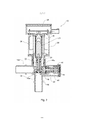
[0027] Fig. 1 é uma vista lateral em perspectiva de uma válvula de alívio de pressão de acordo com um exemplo do objeto presentemente revelado;[0027] Fig. 1 is a perspective side view of a pressure relief valve according to an example of the presently disclosed object;
[0028] Fig. 2 é uma vista em corte longitudinal da válvula de alívio de pressão da Fig. 1;[0028] Fig. 2 is a longitudinal sectional view of the pressure relief valve of Fig. 1;
[0029] Fig. 3A é uma vista lateral em corte ampliada de uma porção da válvula de alívio de pressão da Fig. 1;[0029] Fig. 3A is an enlarged sectional side view of a portion of the pressure relief valve of Fig. 1;
[0030] Fig. 3B é uma vista explodida de uma válvula de purga de acordo com um exemplo do objeto presentemente revelado integrado na válvula de alívio de pressão da Fig. 1;[0030] Fig. 3B is an exploded view of a bleed valve according to an example of the presently disclosed object integrated into the pressure relief valve of Fig. 1;
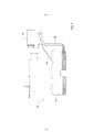
[0031] Fig. 4 é uma ilustração de um diagrama de bloco de um sistema de vapor de combustível de veículo possuindo uma válvula de alívio de pressão de acordo com um exemplo do objeto presentemente revelado;[0031] Fig. 4 is a block diagram illustration of a vehicle fuel vapor system having a pressure relief valve in accordance with an example of the presently disclosed object;
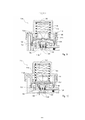
[0032] Fig. 5A é uma vista em corte longitudinal da válvula de alívio de pressão da Fig. 1 na posição totalmente fechada;[0032] Fig. 5A is a longitudinal sectional view of the pressure relief valve of Fig. 1 in the fully closed position;
[0033] Fig. 5B é uma vista em corte longitudinal da válvula de alívio de pressão da Fig. 1 na posição aberta;[0033] Fig. 5B is a longitudinal sectional view of the pressure relief valve of Fig. 1 in the open position;
[0034] Fig. 6A é uma vista em corte longitudinal da válvula de alívio de pressão da Fig. 1 em uma posição sob condições de sobrepressão;[0034] Fig. 6A is a longitudinal sectional view of the pressure relief valve of Fig. 1 in a position under overpressure conditions;
[0035] Fig. 6B é uma vista em corte longitudinal da válvula de alívio de pressão da Fig. 1 em uma posição sob condições de vácuo.[0035] Fig. 6B is a longitudinal sectional view of the pressure relief valve of Fig. 1 in a position under vacuum conditions.
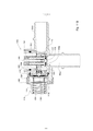
[0036] Fig. 7 é uma vista lateral em corte de uma válvula de sobrepressão de acordo com um outro exemplo do objeto presentemente revelado em um estado fechado;[0036] Fig. 7 is a sectional side view of an overpressure valve according to another example of the presently disclosed object in a closed state;
[0037] Fig. 8 é uma vista em corte lateral da válvula de sobrepressão da Fig. 7 em um seu estado aberto parcialmente de sobrepressão;[0037] Fig. 8 is a side sectional view of the overpressure valve of Fig. 7 in a partially overpressure open state thereof;
[0038] Fig. 9 é uma vista em corte lateral da válvula de sobrepressão da Fig. 7 em um seu estado aberto de sobrepressão;[0038] Fig. 9 is a side sectional view of the overpressure valve of Fig. 7 in an overpressure open state thereof;
[0039] Fig. 10 é uma vista em corte lateral da válvula de sobrepressão da Fig. 7 em um estado aberto de subpressão;[0039] Fig. 10 is a side sectional view of the overpressure valve of Fig. 7 in an open underpressure state;
[0040] Fig. 11A é uma vista explodida isométrica de um corpo de válvula com a válvula de sobrepressão da Fig. 7 integrado nele; e,[0040] Fig. 11A is an isometric exploded view of a valve body with the overpressure valve of Fig. 7 integrated therein; and,
[0041] Fig. 11B é uma vista em corte lateral do corpo de válvula da Fig. 11A com uma válvula atuada externamente montado nele.[0041] Fig. 11B is a side sectional view of the valve body of Fig. 11A with an externally actuated valve mounted on it.
[0042] As Figs. 1 e 2 mostram uma válvula de alívio de pressão (10) compreendendo uma estrutura de acondicionamento (12) possuindo uma primeira tubagem (14a) conectável a um primeiro reservatório (não mostrado), por exemplo um tanque de combustível (como mostrado na Fig. 4), e uma segunda tubagem (14b) conectável a um segundo reservatório, por exemplo um dispositivo de tratamento de vapor de combustível (como mostrado na Fig. 4). A estrutura de acondicionamento (12) inclui ainda uma válvula atuada externamente (doravante denominada válvula EA) (20) disposta nela e sendo configurada para abrir e fechar seletivamente uma porta principal (18a) prolongando-se entre a primeira e segunda tubagem (14a) e (14b). A válvula EA (20) é configurada para atuação pulsada por um controlador (28) e permite assim fluxo de fluido pulsado através da porta principal (18a). A estrutura de acondicionamento (12) inclui ainda uma válvula de sobrepressão (doravante denominada OP) (40) sendo configurada para abrir e fechar seletivamente uma porta de sobrepressão (18b) prolongando-se entre a primeira e segunda tubagem (14a) e (14b). A válvula OP (40) pode ser configurada para permitir o fluxo de fluido através da porta de sobrepressão (18b) em resposta a um gradiente de pressão predeterminado entre a primeira tubagem (14a) a segunda tubagem (14b).[0042] Figs. 1 and 2 show a pressure relief valve (10) comprising a housing (12) having a first pipeline (14a) connectable to a first reservoir (not shown), for example a fuel tank (as shown in Fig. 4), and a second pipeline (14b) connectable to a second reservoir, for example a fuel vapor treatment device (as shown in Fig. 4). The housing (12) further includes an externally actuated valve (hereinafter referred to as valve EA) (20) disposed therein and being configured to selectively open and close a main port (18a) extending between the first and second pipelines (14a) and (14b). The EA valve (20) is configured for pulsed actuation by a controller (28) and thus allows pulsed fluid flow through the main port (18a). The housing (12) further includes an overpressure valve (hereinafter referred to as OP) (40) being configured to selectively open and close an overpressure port (18b) extending between the first and second pipelines (14a) and (14b) ). The OP valve (40) can be configured to allow fluid to flow through the overpressure port (18b) in response to a predetermined pressure gradient between the first pipeline (14a) and the second pipeline (14b).
[0043] A válvula EA (20) pode ser qualquer válvula que é atuada por uma fonte de energia externa, em vez de ser atuada pelo gradiente de pressão ao longo da estrutura de acondicionamento (12), por exemplo diferença de pressão entre a primeira tubagem (14a) e a segunda tubagem (14b). De acordo com um exemplo do objeto presentemente revelado, a válvula EA é um válvula eletromecânica, aqui ilustrada como solenóide, caso contrário a válvula EA pode ser atuada de forma pneumática, ou atuada por meio de qualquer fonte de energia externa.[0043] The EA valve (20) can be any valve that is actuated by an external power source, rather than being actuated by the pressure gradient along the housing (12), for example pressure difference between the first pipe (14a) and the second pipe (14b). According to an example of the presently disclosed object, the valve EA is an electromechanical valve, here illustrated as a solenoid, otherwise the valve EA can be actuated pneumatically, or actuated by means of any external power source.
[0044] No presente exemplo, a válvula EA (20) inclui o corpo solenóide (21) possuindo uma armadura (22) seletivamente prolongando-se para dentro ou para fora do corpo solenóide. A armadura (22) pode ser acionada por uma mola solenóide (24) disposta de forma a que a armadura se prolongue normalmente para fora do corpo solenóide (21). A válvula EA (20) inclui ainda um êmbolo (30) possuindo uma cabeça de êmbolo (32) e um vedante (34) configurado para engatar de forma vedante a porta principal (18a). O êmbolo (30) é montado na armadura (22) de forma que quando a última se prolongue para fora do corpo solenóide (21) a cabeça do êmbolo (32) engate na porta principal (18a), evitando o fluxo de fluido através dela.[0044] In the present example, the EA valve (20) includes the solenoid body (21) having an armature (22) selectively extending into or out of the solenoid body. The armature (22) can be actuated by a solenoid spring (24) arranged so that the armature normally extends out of the solenoid body (21). Valve EA (20) further includes a plunger (30) having a plunger head (32) and a seal (34) configured to sealingly engage the main port (18a). The plunger (30) is mounted on the armature (22) so that when the latter extends out of the solenoid body (21) the plunger head (32) engages the main port (18a), preventing fluid flow through it. .
[0045] De acordo com um exemplo, a mola solenóide (24) apoia-se em um seu lado contra uma porção de ombro definida no êmbolo (30), e no seu outro lado apoia-se contra um corpo solenóide (21).[0045] According to an example, the solenoid spring (24) is supported on one side against a shoulder portion defined on the piston (30), and on its other side it is supported against a solenoid body (21).
[0046] O corpo solenóide (21) inclui ainda uma bobina (26) envolvida em volta dele e configurada para energizar a armadura (22) fazendo com que recue para o corpo solenóide (21) ao ultrapassar a força de ação da mola (24).[0046] The solenoid body (21) also includes a coil (26) wrapped around it and configured to energize the armature (22) causing it to recoil towards the solenoid body (21) when overcoming the spring action force (24). ).
[0047] De acordo com um exemplo, a válvula EA (20) é ativada por um controlador (28) que é adaptado para receber energia elétrica de um alternador de veículo ou de qualquer outro dispositivo de armazenamento de energia (não mostrado). O controlador (27) é configurado para formar um sinal pulsado de forma a permitir atuação pulsada da solenóide como explicado em detalhe de seguida. O controlador (27) pode ser configurado para receber um sinal de atuação do computador do veículo e pode incluir uma placa de circuito que forma um sinal pulsado como exigido. A válvula EA (20) pode ser configurada para estar normalmente fechada, e pode estar aberta apenas em resposta a uma atuação por parte do controlador (27), por exemplo, um sinal elétrico.[0047] According to one example, the EA valve (20) is activated by a controller (28) which is adapted to receive electrical power from a vehicle alternator or any other energy storage device (not shown). The controller (27) is configured to form a pulsed signal in order to allow pulsed actuation of the solenoid as explained in detail below. The controller (27) may be configured to receive an actuation signal from the vehicle's computer and may include a circuit board that forms a pulsed signal as required. The EA valve (20) may be configured to be normally closed, and may be open only in response to an actuation by the controller (27), for example, an electrical signal.
[0048] A válvula EA (20) pode ser disposta perpendicularmente em relação à primeira tubagem (14a). Desta forma, no caso da primeira tubagem (14a) estar acoplada a uma saída de vapor de combustível de um tanque de combustível, o fluxo de fluido do tanque empurra a cabeça do êmbolo (32) na direção da porta principal (18a), e a pressão no interior do tanque facilita a manutenção da válvula EA (20) na posição fechada.[0048] The EA valve (20) can be arranged perpendicularly to the first pipe (14a). In this way, in case the first pipe (14a) is coupled to a fuel vapor outlet of a fuel tank, the fluid flow from the tank pushes the piston head (32) towards the main port (18a), and the pressure inside the tank makes it easier to keep the EA valve (20) in the closed position.
[0049] A válvula de sobrepressão (doravante denominada válvula OP) (40), como vista melhor nas Figs. 3A e 3B, inclui um eixo (42) sendo acionado por uma mola de eixo (43) e configurada com uma cabeça de eixo (44) e uma protrusão vedante (47) definida em volta da sua periferia. A protrusão vedante (47) é configurada para engatar de forma vedante uma ranhura correspondente (51) definida sobre a periferia da porta de sobrepressão (18b). A mola de eixo (43) é montada sobre o eixo (42) e apoia-se contra a estrutura de acondicionamento (12) em uma sua extremidade e contra a cabeça de eixo (44) na sua outra extremidade, empurrando assim a última para engatar de forma vedante a porta de sobrepressão (18b).[0049] The overpressure valve (hereinafter referred to as the OP valve) (40), as best seen in Figs. 3A and 3B, includes an axle (42) being biased by an axle spring (43) and configured with an axle head (44) and a sealing protrusion (47) defined around its periphery. The sealing protrusion (47) is configured to sealingly engage a corresponding groove (51) defined on the periphery of the overpressure port (18b). The axle spring (43) is mounted on the axle (42) and rests against the housing (12) at one end and against the axle head (44) at its other end, thus pushing the latter towards sealingly engage the overpressure port (18b).
[0050] A válvula OP (40) inclui ainda uma válvula de purga (41) compreendendo um pistão (46) montado de lado no interior do eixo (42) e através de uma abertura de purga (55) formada na cabeça de eixo (44). O pistão (46) pode incluir uma cabeça de pistão (53) definida em uma sua extremidade configurada para engatar de forma vedante a abertura de purga (55). A sua outra extremidade está acoplada a um membro de apoio 49 possuindo um diâmetro inferior ao da mola de eixo (43). Um vedante (45) possuindo uma abertura de purga correspondente (55a) está montado entre a cabeça de eixo (44) e a cabeça de pistão (53) e é configurado para engatar de forma vedante a porta de sobrepressão (18b). A periferia do vedante (45) está disposta entre a cabeça de eixo (44) e a parede da porta de sobrepressão (18b).[0050] The OP valve (40) further includes a bleed valve (41) comprising a piston (46) mounted sideways inside the shaft (42) and through a bleed opening (55) formed in the shaft head ( 44). The piston (46) may include a piston head (53) defined at one end thereof configured to sealingly engage the bleed opening (55). Its other end is coupled to a
[0051] O pistão (46) é acionado por uma mola de pistão (50) apoiando-se contra o membro de suporte (49) em um seu lado e contra a cabeça de eixo (44) na sua outra extremidade. A mola de pistão (50) é configurada com um diâmetro inferior ao da mola de eixo (43). Em conformidade, o pistão (46), a mola de pistão (50) e o membro de suporte (49) são dispostos no interior da periferia da mola de eixo de forma que a válvula de purga (41) possa operar independentemente do eixo (42).[0051] The piston (46) is driven by a piston spring (50) bearing against the support member (49) on one side thereof and against the shaft head (44) on its other end. The piston spring (50) is configured with a smaller diameter than the shaft spring (43). Accordingly, the piston (46), the piston spring (50) and the support member (49) are arranged within the periphery of the shaft spring so that the bleed valve (41) can operate independently of the shaft ( 42).
[0052] A válvula OP (40) é configurada de forma que a pressão na primeira tubagem (14a) excedendo um limiar predeterminado possa ultrapassar a força de ação (43), pelo que a protrusão vedante (47) da cabeça de eixo (44) desliza para longe da correspondente ranhura (51), permitindo a passagem de fluxo de fluido através da porta de sobrepressão (18b). Quando a pressão na segunda tubagem (14a) excede um limiar predeterminado, a força de ação da mola de pistão (50) é ultrapassada, pelo que o pistão (46) é deslocado na direção da porta (18b).[0052] The OP valve (40) is configured so that the pressure in the first pipe (14a) exceeding a predetermined threshold can exceed the action force (43), whereby the sealing protrusion (47) of the shaft head (44) ) slides away from the corresponding slot (51), allowing fluid flow to pass through the overpressure port (18b). When the pressure in the second line (14a) exceeds a predetermined threshold, the force of action of the piston spring (50) is overcome, whereby the piston (46) is moved towards the port (18b).
[0053] De acordo com um exemplo, a válvula OP é disposta coaxialmente em relação à primeira tubagem (14a), pelo que a pressão ou fluxo de fluido da primeira tubagem é aplicado diretamente na cabeça de eixo (44) facilitando a sua abertura caso a pressão na primeira tubagem (14a) exceda um certo limiar.[0053] According to an example, the OP valve is arranged coaxially in relation to the first pipe (14a), so that the pressure or fluid flow from the first pipe is applied directly to the shaft head (44) facilitating its opening if necessary. the pressure in the first line (14a) exceeds a certain threshold.
[0054] Assim, caso a primeira tubagem (14a) esteja acoplada a uma saída de vapor de combustível de um tanque de combustível, quando a pressão no tanque excede um nível predeterminado, a cabeça de eixo (44) da válvula OP (40) é aberta, permitindo assim o fluxo de fluido desde a primeira tubagem até à segunda tubagem 14b, mesmo caso a válvula EA (20) esteja fechada.[0054] Thus, if the first pipe (14a) is coupled to a fuel vapor outlet of a fuel tank, when the pressure in the tank exceeds a predetermined level, the shaft head (44) of the OP valve (40) is open, thus allowing the flow of fluid from the first line to the
[0055] É feita agora referência à Fig. 4, onde a válvula de alívio de pressão pode ser integrada em um sistema de vapor de combustível de veículo geralmente designado (60) e possuindo um tanque de combustível (62) e um dispositivo de tratamento de vapor (64), tal como um recipiente. O tanque de combustível (62) é acoplado a um gargalo de enchimento (66) e inclui um tubo de saída de vapor de combustível 68, que está acoplado a uma primeira tubagem da válvula de alívio de pressão (70). Uma segunda tubagem prolongando-se desde a válvula de alívio de pressão (70) está acoplada ao dispositivo de tratamento de vapor (64), que pode ser aberto para a atmosfera.[0055] Reference is now made to Fig. 4, where the pressure relief valve may be integrated into a generally designated vehicle fuel vapor system (60) and having a fuel tank (62) and a vapor treatment device (64), such as a container. . The fuel tank (62) is coupled to a filler neck (66) and includes a fuel
[0056] Segue-se uma explicação detalhada da operação da válvula de alívio de pressão como descrita nas Figs. 1 a 3B, contudo, no caso em que a válvula é integrada em um sistema de vapor de combustível e montada em um trajeto de vapor de combustível entre um tanque de combustível e um dispositivo de tratamento de vapor de combustível, de seguida referido como um recipiente.[0056] The following is a detailed explanation of the operation of the pressure relief valve as described in Figs. 1 to 3B, however, in the case where the valve is integrated into a fuel vapor system and mounted in a fuel vapor path between a fuel tank and a fuel vapor treatment device, hereinafter referred to as a container.
[0057] A válvula de alívio de pressão (10) permite abrir a válvula EA (20) em resposta a um sinal, por exemplo um sinal elétrico proveniente do computador do veículo, e a válvula OP (40) pode abrir em resposta a um gradiente de pressão na válvula maior do que um gradiente predeterminado. Ou seja, no caso em que a primeira tubagem (14a) é acoplada a um tanque de combustível (como mostrado na Fig. 4) e a segunda tubagem (14b) está acoplada a um recipiente, quando a pressão no tanque excede um nível predeterminado, a válvula OP (40) pode ser aberta de forma a levar o nível de pressão no tanque até ao intervalo de pressão desejado. De forma semelhante, quando a pressão no tanque desce abaixo de um nível predeterminado, a válvula de purga (41) pode ser aberta de forma a levar o nível de pressão no tanque ao intervalo de pressão desejado.[0057] The pressure relief valve (10) allows opening the EA valve (20) in response to a signal, for example an electrical signal from the vehicle's computer, and the OP valve (40) can open in response to a pressure gradient across the valve greater than a predetermined gradient. That is, in the case where the first pipe (14a) is coupled to a fuel tank (as shown in Fig. 4) and the second pipe (14b) is coupled to a container, when the pressure in the tank exceeds a predetermined level , the OP valve (40) can be opened to bring the pressure level in the tank to the desired pressure range. Similarly, when the pressure in the tank drops below a predetermined level, the bleed valve (41) can be opened to bring the pressure level in the tank to the desired pressure range.
[0058] A Fig. 5A mostra a válvula de alívio de pressão (10) em uma posição totalmente fechada na qual tanto a válvula EA (20) como a válvula OP (40) estão fechadas. Em esta posição, a cabeça do êmbolo (32) da válvula EA (20) engata de forma vedante a porta principal (18a) e a cabeça de eixo (44) da válvula OP engata de forma vedante a porta de sobrepressão (18b). Assim, em esta posição, o vapor de combustível flui desde a primeira tubagem (14a) para a segunda tubagem 14b, e assim é impedida uma forma de acesso do tanque para o recipiente. Sabe-se que é esta posição que o êmbolo (30) opera sob força da mola (24) empurrando o vedante 34 na porta principal (18a). Assim, em esta posição, não há necessidade de energia de uma fonte externa para energizar a válvula EA (20).[0058] Fig. 5A shows the pressure relief valve (10) in a fully closed position in which both the EA valve (20) and the OP valve (40) are closed. In this position, the piston head (32) of the EA valve (20) sealingly engages the main port (18a) and the shaft head (44) of the OP valve sealingly engages the overpressure port (18b). Thus, in this position, fuel vapor flows from the first line (14a) to the
[0059] A Fig. 5B mostra a válvula de alívio de pressão (10) na sua posição aberta, em que a válvula EA (20) está aberta, enquanto a válvula OP (40) permanece fechada. Em esta posição, a cabeça do êmbolo (32) da válvula EA (20) desengata a porta principal 18a permitindo assim o fluxo de vapor desde o tanque na direção do recipiente. Abrir a válvula EA (20) é realizado em resposta a um sinal pulsado pelo controlador (27) que no caso de um solenóide energiza a bobina (26) enrolada no corpo solenóide (21) provocando assim um deslocamento pulsado da armadura (22), afastando-o da porta principal (18a). No fim de cada impulso, a mola (24) força a armadura (22) e o êmbolo (30) a voltarem a engatar na porta principal (18a). Assim, como resultado do sinal pulsado pelo controlador (27), é formado um fluxo de fluido pulsado entre a primeira tubagem (14a) e a segunda tubagem (14b). Desta forma, é permitido um fluxo de vapor desde o tanque para o recipiente de uma forma pulsada, de forma que não provoque o rolhamento de outra válvulas de vapor de combustível acopladas ao tanque de maneira que possam ser entupidas pela força de elevação do súbito fluxo de vapor de alta velocidade.[0059] Fig. 5B shows the pressure relief valve (10) in its open position, where the EA valve (20) is open, while the OP valve (40) remains closed. In this position, the piston head (32) of the valve EA (20) disengages the
[0060] Em conformidade, o sinal pulsado pode ser configurado com impulsos possuindo um comprimento e amplitude de onda que permita liberação medida de pressão, de forma a não resultar no mau funcionamento de outro acessório de vapor de combustível. De acordo com um exemplo, cada impulso pode ter no máximo 200 milissegundos e pode ser repetido 3 ou 4 vezes ou mais, com um intervalo de pelo menos 200 milissegundos entre os impulsos.[0060] Accordingly, the pulsed signal can be configured with pulses having a wavelength and amplitude that allow measured pressure release, so as not to result in the malfunction of another fuel vapor accessory. According to one example, each pulse may be a maximum of 200 milliseconds and may be repeated 3 or 4 times or more, with an interval of at least 200 milliseconds between pulses.
[0061] Sabe-se que o sinal pode ser atuado em ocasiões em que o tanque de combustível está prestes a ser aberto, por exemplo antes do seu reabastecimento, onde se pretende liberar pressão do tanque de combustível e levá-lo a um equilíbrio substancial com a atmosfera. Em conformidade, os impulsos podem ser configurados de acordo com o tempo esperado, uma vez que se reconhece que o tanque do veículo está prestes a ser reabastecido até que ocorra efetivamente a abertura do tanque de combustível. Ou seja, se por exemplo abrir a porta de combustível for utilizado como mecanismo desencadeador a seguir ao qual se espera que o tanque de combustível seja aberto, o intervalo de tempo durante o qual a pressão no tanque deve ser liberada é o tempo previsto entre a abertura da porta de combustível e a efetiva abertura do tanque de combustível. De acordo com alguns exemplos, o intervalo de tempo previsto é de 2 segundos; assim, o sinal pulsado é configurado para permitir a liberação substancial de pressão do tanque no espaço de 2 segundos.[0061] It is known that the signal can be triggered on occasions when the fuel tank is about to be opened, for example before refueling, where it is intended to release pressure from the fuel tank and bring it to a substantial equilibrium. with the atmosphere. Accordingly, the pulses can be configured according to the expected time, as it is recognized that the vehicle's tank is about to be refilled until the fuel tank actually opens. That is, if, for example, opening the fuel door is used as a triggering mechanism after which the fuel tank is expected to be opened, the time interval during which the pressure in the tank must be released is the predicted time between opening the fuel door and effectively opening the fuel tank. According to some examples, the predicted time interval is 2 seconds; thus, the pulsed signal is configured to allow substantial release of pressure from the tank within 2 seconds.
[0062] De acordo com o último exemplo, abrir a porta de combustível pode automaticamente atuar um sinal para atuar o controlador (27), que por sua vez forma um sinal pulsado para ditar a operação da válvula solenóide (20). Reconhece-se que podem ser utilizados outros mecanismos desencadeadores, de forma que a atuação do sinal pulsado seja realizada dentro de um intervalo de tempo predeterminado antes da abertura do tanque de combustível.[0062] According to the last example, opening the fuel door can automatically trigger a signal to trigger the controller (27), which in turn forms a pulsed signal to dictate the operation of the solenoid valve (20). It is recognized that other triggering mechanisms can be used, so that the pulsed signal is activated within a predetermined time interval before the fuel tank is opened.
[0063] Reconhece-se ainda que uma vez liberada a pressão no tanque de combustível, após a abertura pulsada da válvula EA (20), a válvula pode ser continuamente aberta sem impulsos, por exemplo para permitir o reabastecimento do tanque. Reconhece-se assim que a quantidade de energia elétrica necessária para formar os impulsos pode ser superior à quantidade de energia necessária para manter a válvula EA (20) na sua posição aberta contínua. Isto fica a dever-se ao fato de que abrir a válvula EA (20), quando o tanque de combustível está sob alta pressão, exige mais energia do que manter a válvula EA aberta após a pressão ser liberada do tanque. Em conformidade, o sinal pulsado atuado pelo controlador (27) pode incluir impulsos possuindo elevada amplitude de tensão, enquanto no último impulso, ao seguir ao qual a válvula EA (20) permanece aberta, a amplitude de voltagem pode ser inferior. Desta forma, é impedido o sobreaquecimento da válvula EA (20).[0063] It is also recognized that once the pressure in the fuel tank is released, after the pulsed opening of the EA valve (20), the valve can be continuously opened without impulses, for example to allow the tank to be refilled. It is thus recognized that the amount of electrical energy required to form the pulses may be greater than the amount of energy required to maintain valve EA (20) in its continuously open position. This is because opening the EA valve (20) when the fuel tank is under high pressure requires more energy than holding the EA valve open after the pressure is released from the tank. Accordingly, the pulsed signal actuated by controller (27) may include pulses having high voltage amplitude, while in the last pulse, following which valve EA (20) remains open, the voltage amplitude may be lower. In this way, overheating of the EA valve (20) is prevented.
[0064] Com referência agora à Fig. 6A, a válvula de alívio de pressão 10 pode ser aberta em resposta a uma elevada pressão do lado da primeira tubagem (14a), tal como quando a pressão no tanque de combustível excede um nível predeterminado. Em esta posição, as forças aplicadas pela pressão dentro do tanque ultrapassam as forças da mola de eixo (43) pressionando o eixo (42) da válvula OP (40), o que resulta no desengate da protrusão vedante (47) da cabeça de eixo (44) em relação à ranhura (51) definida em volta da periferia na porta de sobrepressão (18b) podendo assim ser liberada a pressão de dentro do tanque ao permitir que o fluxo de vapor proveniente dele passe através da porta de sobrepressão na direção do recipiente.[0064] Referring now to Fig. 6A, the
[0065] Reconhece-se que a operação da válvula OP (40) pode ser configurada como uma válvula de emergência evitando uma sobrepressão no tanque que possa causar danos ao tanque. Assim, em condição normal, a válvula OP (40) permanece fechada.[0065] It is recognized that the operation of the OP valve (40) can be configured as an emergency valve preventing an overpressure in the tank that could cause damage to the tank. Thus, in normal condition, the OP valve (40) remains closed.
[0066] Em relação à válvula EA (20), em esta posição a última permanece fechada sob as forças da mola (24) que pressionam o vedante (34) na porta principal (18a). Assim, tal como na posição totalmente fechada, não há necessidade de energia de uma fonte externa para energizar a válvula EA (20), e a válvula OP (40) pode operar independentemente apenas em resposta à pressão no tanque.[0066] Regarding the EA valve (20), in this position the latter remains closed under the forces of the spring (24) that press the seal (34) on the main port (18a). Thus, as in the fully closed position, there is no need for power from an external source to energize the EA valve (20), and the OP valve (40) can operate independently only in response to pressure in the tank.
[0067] Com referência agora à Fig. 6B, a válvula de alívio de pressão (10) pode ser aberta em resposta a uma baixa pressão do lado da primeira tubagem (14a), tal como quando a pressão no tanque de combustível desce abaixo de um nível predeterminado, por exemplo quando se forma vácuo no tanque. Em esta posição, as forças aplicadas pela pressão dentro do tanque ultrapassam as forças da mola do pistão (50) acionado o pistão (46) da válvula de purga (41) e afastando-o da porta de sobrepressão (18b). Em resultado, a cabeça do pistão (53) é movida para dentro desengatando da cabeça de eixo (44), permitindo assim o fluxo de fluido através da abertura de purga (55) formada aí. Uma vez que a periferia do vedante (45) está disposta entre a cabeça de eixo (44) e a parede da porta de sobrepressão (18b), quando a cabeça de pistão (53) é afastada da cabeça de eixo (44), a periferia do vedante permanece no local enquanto o seu centro é deformado para dentro. Em esta posição, o fluxo de fluido através das aberturas de purga (55) na correspondente válvula de purga 55a é facilitado, permitindo assim que seja liberado o vácuo do interior do tanque.[0067] Referring now to Fig. 6B, the pressure relief valve (10) can be opened in response to a low pressure on the side of the first line (14a), such as when the pressure in the fuel tank drops below a predetermined level, for example when it builds up. vacuum in the tank. In this position, the forces applied by the pressure within the tank exceed the forces of the piston spring (50) actuating the piston (46) of the bleed valve (41) and away from the overpressure port (18b). As a result, the piston head (53) is moved inwardly in disengagement from the shaft head (44), thus allowing fluid to flow through the bleed opening (55) formed therein. Since the periphery of the seal (45) is arranged between the shaft head (44) and the wall of the overpressure port (18b), when the piston head (53) is moved away from the shaft head (44), the periphery of the seal remains in place while its center is deformed inwardly. In this position, the flow of fluid through the bleed openings (55) in the
[0068] Os entendidos na técnica à qual o objeto presentemente revelado pertence reconhecerão prontamente que podem ser feitas várias alterações, variações e modificações sem sair do escopo da invenção, mutatis mutandis.[0068] Those skilled in the art to which the presently disclosed object pertains will readily recognize that various alterations, variations and modifications may be made without departing from the scope of the invention, mutatis mutandis.
Claims (15)
Applications Claiming Priority (5)
| Application Number | Priority Date | Filing Date | Title |
|---|---|---|---|
| US201461933371P | 2014-01-30 | 2014-01-30 | |
| US61/933,371 | 2014-01-30 | ||
| US201462075289P | 2014-11-05 | 2014-11-05 | |
| US62/075,289 | 2014-11-05 | ||
| PCT/IL2015/050032 WO2015114618A1 (en) | 2014-01-30 | 2015-01-08 | Pressure relief valve |
Publications (2)
| Publication Number | Publication Date |
|---|---|
| BR112016017713A2 BR112016017713A2 (en) | 2017-08-08 |
| BR112016017713B1 true BR112016017713B1 (en) | 2022-05-03 |
Family
ID=52469254
Family Applications (1)
| Application Number | Title | Priority Date | Filing Date |
|---|---|---|---|
| BR112016017713-4A BR112016017713B1 (en) | 2014-01-30 | 2015-01-08 | PRESSURE RELIEF VALVE, AND METHOD TO EVACUATE FUEL STEAM FROM A FUEL TANK TO A FUEL STEAM TREATMENT DEVICE |
Country Status (8)
| Country | Link |
|---|---|
| US (1) | US10717353B2 (en) |
| EP (1) | EP3099520A1 (en) |
| JP (1) | JP6718374B2 (en) |
| KR (1) | KR102341808B1 (en) |
| CN (1) | CN106132751B (en) |
| BR (1) | BR112016017713B1 (en) |
| RU (1) | RU2671456C2 (en) |
| WO (1) | WO2015114618A1 (en) |
Families Citing this family (13)
| Publication number | Priority date | Publication date | Assignee | Title |
|---|---|---|---|---|
| KR102529556B1 (en) | 2015-11-23 | 2023-05-04 | 라발 에이.씨.에스. 엘티디 | Solenoid assembly for valve |
| FR3078294B1 (en) * | 2018-02-23 | 2020-05-22 | Valeo Systemes De Controle Moteur | SAFETY DEVICE FOR FUEL TANK |
| WO2019206460A1 (en) * | 2018-04-24 | 2019-10-31 | Eaton Intelligent Power Limited | Fuel tank isolation valve having connection architecture and pressure sensing device |
| JP6983728B2 (en) * | 2018-06-06 | 2021-12-17 | 愛三工業株式会社 | Fluid control valve and evaporative fuel treatment equipment |
| CN114502407A (en) * | 2019-09-04 | 2022-05-13 | 帕德米尼机电有限公司 | Improved fuel tank isolation valve with integrated stepper motor and improved plunger |
| WO2021044395A1 (en) * | 2019-09-04 | 2021-03-11 | Padmini Vna Mechatronics Pvt. Ltd. | An improved fuel tank isolation valve with an integrated stepper motor |
| WO2021124304A1 (en) * | 2019-12-20 | 2021-06-24 | Padmini Vna Mechatronics Pvt. Ltd. | Fuel tank isolation valve for compact solenoid valve |
| CN116075632A (en) * | 2020-09-07 | 2023-05-05 | 戴科知识产权控股有限责任公司 | Magnetic latching valve for fuel vapor management system and system including the same |
| US20220080991A1 (en) * | 2020-09-11 | 2022-03-17 | Beijing Wodong Tianjun Information Technology Co., Ltd. | System and method for reducing uncertainty in estimating autonomous vehicle dynamics |
| CN116783417B (en) * | 2021-01-02 | 2024-04-05 | 戴科知识产权控股有限责任公司 | Magnetic latching valve for fuel vapor management system and system including the same |
| EP4271923A1 (en) * | 2021-01-02 | 2023-11-08 | Dayco IP Holdings, LLC | Magnetically latching valve for fuel vapor management systems and systems incorporating same |
| KR20220134150A (en) | 2021-03-26 | 2022-10-05 | 현대자동차주식회사 | Fuel tank isolation solenoid valve for vehicle |
| KR20220168376A (en) | 2021-06-16 | 2022-12-23 | 현대자동차주식회사 | Isolation valve |
Family Cites Families (41)
| Publication number | Priority date | Publication date | Assignee | Title |
|---|---|---|---|---|
| US3344050A (en) | 1964-02-03 | 1967-09-26 | Girdler Corp | Removal of carbon dioxide from gaseous atmospheres |
| US3441050A (en) | 1966-07-13 | 1969-04-29 | Itt | Pressure equalizing valve |
| JPS4921232U (en) | 1972-05-25 | 1974-02-22 | ||
| JPS5069421A (en) * | 1973-10-24 | 1975-06-10 | ||
| JPS512742U (en) * | 1974-06-20 | 1976-01-10 | ||
| JPS512742A (en) | 1974-06-28 | 1976-01-10 | Dainippon Ink & Chemicals | |
| US4317467A (en) | 1980-07-10 | 1982-03-02 | Illinois Tool Works Inc. | Two-way pressure relief valve |
| US4679580A (en) | 1986-06-23 | 1987-07-14 | Borg-Warner Automotive, Inc. | Vapor vent control valve |
| JPH04105959A (en) | 1990-08-27 | 1992-04-07 | Nec Niigata Ltd | Enlarging printing control system |
| US5069188A (en) * | 1991-02-15 | 1991-12-03 | Siemens Automotive Limited | Regulated canister purge solenoid valve having improved purging at engine idle |
| JP2522391Y2 (en) | 1991-02-27 | 1997-01-16 | 本田技研工業株式会社 | Fuel evaporative emission control system |
| GB2269375A (en) | 1992-08-08 | 1994-02-09 | Ford Motor Co | A vent valve for a vehicle fuel tank |
| JPH0771335A (en) * | 1993-08-30 | 1995-03-14 | Toyoda Gosei Co Ltd | Fuel storage device |
| US5509395A (en) * | 1995-03-31 | 1996-04-23 | Siemens Electric Limited | Canister purge flow regulator |
| US5855225A (en) | 1998-01-29 | 1999-01-05 | Williams, Iii; James W. | Tank transport pressure relief valve assembly |
| US6196258B1 (en) * | 1998-04-16 | 2001-03-06 | Calsonic Corporation | Pressure control valve and evaporation fuel discharge control device |
| US6006781A (en) | 1998-07-01 | 1999-12-28 | Parr Manufacturing, Inc. | Fuel pressure regulator |
| DE19948969A1 (en) | 1999-10-12 | 2001-04-19 | Bosch Gmbh Robert | Control device for vehicle drive train has electronic components with different high loss powers, those used for gearbox control integrated into gearbox control apparatus |
| US6481592B2 (en) | 2001-04-23 | 2002-11-19 | Stant Manufacturing Inc. | Fuel tank vent valve |
| DE10248843B4 (en) | 2002-10-19 | 2005-01-20 | Daimlerchrysler Ag | Device for controlling a motor or gearbox |
| US7207347B2 (en) | 2004-08-23 | 2007-04-24 | Raval A.S.C. Ltd. | Dual function valve for fuel tank |
| IL165845A0 (en) | 2004-12-16 | 2006-01-15 | Raval Acs Ltd | Vapor recovery control valve |
| JP2006258283A (en) * | 2005-02-18 | 2006-09-28 | Denso Corp | Fluid control valve and solenoid valve |
| JP2006258135A (en) * | 2005-03-15 | 2006-09-28 | Denso Corp | Solenoid valve |
| US8561638B2 (en) | 2008-12-02 | 2013-10-22 | Piolax Inc. | Check valve |
| US8573255B2 (en) | 2009-04-22 | 2013-11-05 | Eaton Corporation | Valve assembly for high-pressure fluid reservoir |
| US8584704B2 (en) | 2009-04-22 | 2013-11-19 | Eaton Corporation | Valve assembly for high-pressure fluid reservoir |
| JP5466984B2 (en) | 2010-04-12 | 2014-04-09 | リンナイ株式会社 | safety valve |
| US8844561B2 (en) | 2010-05-20 | 2014-09-30 | Eaton Corporation | Isolation valve with integrated sensor |
| DE102010044336A1 (en) | 2010-09-03 | 2012-03-08 | A. Kayser Automotive Systems Gmbh | Ventilation arrangement for a fuel tank |
| KR101181065B1 (en) | 2010-12-02 | 2012-09-07 | 기아자동차주식회사 | Fuel Tank Control Valve for Vehicle |
| DE102010054960A1 (en) | 2010-12-17 | 2012-06-21 | Audi Ag | Method for refueling of fuel tank, particularly of motor vehicle, involves maintaining excess pressure against ambient pressure during refueling of fuel tank |
| DE102011015999B4 (en) * | 2011-04-04 | 2015-06-25 | Audi Ag | A method of venting a fuel tank of a vehicle and tank venting device |
| JP5505377B2 (en) * | 2011-07-06 | 2014-05-28 | 株式会社デンソー | Electric on / off valve with forward / reverse relief |
| JP5370437B2 (en) * | 2011-08-29 | 2013-12-18 | 株式会社デンソー | Fluid control solenoid valve |
| WO2013117239A1 (en) | 2012-02-10 | 2013-08-15 | Nokia Siemens Networks Oy | Inter-site carrier aggregation |
| JP2013204510A (en) | 2012-03-28 | 2013-10-07 | Toyota Motor Corp | Fuel tank system |
| JP5573891B2 (en) * | 2012-06-11 | 2014-08-20 | 株式会社デンソー | Relief valve device |
| JP5884778B2 (en) * | 2013-06-26 | 2016-03-15 | 株式会社デンソー | Valve device |
| US20150034180A1 (en) * | 2013-08-02 | 2015-02-05 | Continental Automotive Systems, Inc. | Tank pressure control solenoid with passive tank vacuum relief |
| US9890747B2 (en) * | 2014-05-05 | 2018-02-13 | Continental Automotive Systems, Inc. | Tank pressure control solenoid with passive tank vacuum |
-
2015
- 2015-01-08 KR KR1020167022905A patent/KR102341808B1/en active IP Right Grant
- 2015-01-08 RU RU2016131878A patent/RU2671456C2/en active
- 2015-01-08 BR BR112016017713-4A patent/BR112016017713B1/en active IP Right Grant
- 2015-01-08 WO PCT/IL2015/050032 patent/WO2015114618A1/en active Application Filing
- 2015-01-08 US US15/112,333 patent/US10717353B2/en active Active
- 2015-01-08 CN CN201580016578.9A patent/CN106132751B/en active Active
- 2015-01-08 JP JP2016548662A patent/JP6718374B2/en active Active
- 2015-01-08 EP EP15704101.3A patent/EP3099520A1/en active Pending
Also Published As
| Publication number | Publication date |
|---|---|
| CN106132751B (en) | 2020-05-12 |
| KR102341808B1 (en) | 2021-12-21 |
| WO2015114618A1 (en) | 2015-08-06 |
| RU2016131878A3 (en) | 2018-08-29 |
| KR20160113641A (en) | 2016-09-30 |
| RU2016131878A (en) | 2018-03-02 |
| BR112016017713A2 (en) | 2017-08-08 |
| CN106132751A (en) | 2016-11-16 |
| US10717353B2 (en) | 2020-07-21 |
| US20160375759A1 (en) | 2016-12-29 |
| RU2671456C2 (en) | 2018-10-31 |
| EP3099520A1 (en) | 2016-12-07 |
| JP2017508912A (en) | 2017-03-30 |
| JP6718374B2 (en) | 2020-07-08 |
Similar Documents
| Publication | Publication Date | Title |
|---|---|---|
| BR112016017713B1 (en) | PRESSURE RELIEF VALVE, AND METHOD TO EVACUATE FUEL STEAM FROM A FUEL TANK TO A FUEL STEAM TREATMENT DEVICE | |
| CN107107740B (en) | Pressure reducing valve | |
| US9072925B2 (en) | Valve | |
| US11892108B2 (en) | Lever for auto insertion and secure placement of IV tubing for use in intravenous pump systems | |
| CA2925459C (en) | Fully-integrated flow-control valve assembly for top-filled fuel tanks | |
| US10113510B2 (en) | Valve for methane in automotive systems with by-pass system of the excess flow blocking device | |
| KR102215184B1 (en) | Passive depressurisation system for pressurised receptacles in nuclear reactors | |
| CN106461113A (en) | High integrity pressure protecting system (HIPPS) for a fluid line | |
| BR112019021643A2 (en) | CONTROL DEVICE FOR OPENING / CLOSING A CONTAINER WITH VALVE, ASSEMBLY UNDERSTANDING A CONTAINER WITH VALVE AND SUCH CONTROL DEVICE | |
| KR101106703B1 (en) | Liquid gas supply system with leakage pressure rise prevention valve for pressurized gas leakage | |
| CL2022000293A1 (en) | Unloading valve unit and fluid device | |
| RU2450191C2 (en) | Drain and safety valve | |
| US2441911A (en) | Check valve and storage system containing same | |
| JPS59500280A (en) | Conduits for pressure conduits or hoses with enclosed protective conduits or hoses - breach valves | |
| ITTO20110799A1 (en) | CONNECTING DEVICE FOR CONNECTION TO AN AIR-CONDITIONING SYSTEM AND JOINT PROVIDED WITH SUCH A FITTING DEVICE | |
| RU175263U1 (en) | Safety shut-off valve | |
| WO2015103343A1 (en) | Top fill, fully-integrated pressureless flow-control module operative when tank fluid is frozen | |
| JP6686840B2 (en) | Tanks and hydraulic equipment | |
| BR102014026525B1 (en) | Ink reservoir punch for inking systems |
Legal Events
| Date | Code | Title | Description |
|---|---|---|---|
| B06U | Preliminary requirement: requests with searches performed by other patent offices: procedure suspended [chapter 6.21 patent gazette] | ||
| B09A | Decision: intention to grant [chapter 9.1 patent gazette] | ||
| B16A | Patent or certificate of addition of invention granted [chapter 16.1 patent gazette] |
Free format text: PRAZO DE VALIDADE: 20 (VINTE) ANOS CONTADOS A PARTIR DE 08/01/2015, OBSERVADAS AS CONDICOES LEGAIS. |