BR112016014482B1 - HIGH POWER SWITCH WITH CURRENT LIMITER - Google Patents
HIGH POWER SWITCH WITH CURRENT LIMITER Download PDFInfo
- Publication number
- BR112016014482B1 BR112016014482B1 BR112016014482-1A BR112016014482A BR112016014482B1 BR 112016014482 B1 BR112016014482 B1 BR 112016014482B1 BR 112016014482 A BR112016014482 A BR 112016014482A BR 112016014482 B1 BR112016014482 B1 BR 112016014482B1
- Authority
- BR
- Brazil
- Prior art keywords
- connector
- main contact
- external connector
- current limiter
- arc
- Prior art date
Links
Images


Classifications
-
- H—ELECTRICITY
- H01—ELECTRIC ELEMENTS
- H01H—ELECTRIC SWITCHES; RELAYS; SELECTORS; EMERGENCY PROTECTIVE DEVICES
- H01H33/00—High-tension or heavy-current switches with arc-extinguishing or arc-preventing means
- H01H33/02—Details
- H01H33/04—Means for extinguishing or preventing arc between current-carrying parts
- H01H33/12—Auxiliary contacts on to which the arc is transferred from the main contacts
-
- H—ELECTRICITY
- H01—ELECTRIC ELEMENTS
- H01H—ELECTRIC SWITCHES; RELAYS; SELECTORS; EMERGENCY PROTECTIVE DEVICES
- H01H33/00—High-tension or heavy-current switches with arc-extinguishing or arc-preventing means
- H01H33/02—Details
- H01H33/04—Means for extinguishing or preventing arc between current-carrying parts
- H01H33/16—Impedances connected with contacts
-
- H—ELECTRICITY
- H01—ELECTRIC ELEMENTS
- H01H—ELECTRIC SWITCHES; RELAYS; SELECTORS; EMERGENCY PROTECTIVE DEVICES
- H01H33/00—High-tension or heavy-current switches with arc-extinguishing or arc-preventing means
- H01H33/60—Switches wherein the means for extinguishing or preventing the arc do not include separate means for obtaining or increasing flow of arc-extinguishing fluid
- H01H33/66—Vacuum switches
- H01H33/664—Contacts; Arc-extinguishing means, e.g. arcing rings
-
- H—ELECTRICITY
- H01—ELECTRIC ELEMENTS
- H01H—ELECTRIC SWITCHES; RELAYS; SELECTORS; EMERGENCY PROTECTIVE DEVICES
- H01H33/00—High-tension or heavy-current switches with arc-extinguishing or arc-preventing means
- H01H33/70—Switches with separate means for directing, obtaining, or increasing flow of arc-extinguishing fluid
- H01H33/72—Switches with separate means for directing, obtaining, or increasing flow of arc-extinguishing fluid having stationary parts for directing the flow of arc-extinguishing fluid, e.g. arc-extinguishing chamber
Abstract
interruptor de alta potência com limitador de corrente. interruptor de alta potência com um limitador de corrente, que compreende um circuito condutor principal que consiste de um condutor principal tubular oco, um corpo de conexão interior e exterior, um contato principal fixo e um contato principal móvel anelar (4), e um circuito do setor de extinção de arco que consiste de um dispositivo de ruptura (5) com uma função de extinção de arco e um limitador de corrente (6); o circuito do setor de extinção de arco está ligado em paralelo ao circuito condutor principal; o limitador de corrente (6) serve de elemento constituinte do interruptor, e encontra-se no condutor principal; e quando um interruptor interrompe uma corrente de curto-circuito, o circuito condutor principal interrompe primeiro, e a corrente é transferida para o circuito do setor de extinção de arco, e o limitador de corrente (6) limita uma corrente de curto-circuito para dentro de uma capacitância de ruptura do dispositivo de ruptura (5).high power switch with current limiter. high power switch with a current limiter, comprising a main conductor circuit consisting of a hollow tubular main conductor, an inner and outer connecting body, a fixed main contact and an annular movable main contact (4), and a circuit the arc extinguishing sector consisting of a breaking device (5) with an arc extinguishing function and a current limiter (6); the arc-extinguishing sector circuit is connected in parallel with the main conductor circuit; the current limiter (6) serves as a constituent element of the switch, and is located on the main conductor; and when a switch breaks a short-circuit current, the main conductor circuit breaks first, and the current is transferred to the arc-extinguishing sector circuit, and the current limiter (6) limits a short-circuit current to within a breaking capacitance of the breaking device (5).
Description
[001] Este pedido reivindica prioridade sobre o pedido de patente chinesa n.° 201410453010.0 intitulado “INTERRUPTOR DE ALTA POTÊNCIA COM LIMITADOR DE CORRENTE” e arquivado no Gabinete de Propriedade Intelectual do Estado Chinês a 5 de setembro de 2014, que está incorporado aqui por referência na sua totalidade.[001] This application claims priority over Chinese patent application No. 201410453010.0 entitled “HIGH POWER SWITCH WITH CURRENT LIMITER” and filed with the Chinese State Intellectual Property Office on September 5, 2014, which is incorporated herein by reference in its entirety.
[002] CAMPO[002] FIELD
[003] O presente pedido refere-se ao campo técnico de interruptores elétricos, e em particular à concessão e fabrico de um interruptor de alta potência.[003] The present application relates to the technical field of electrical switches, and in particular to the design and manufacture of a high-power switch.
[004] ANTECEDENTES[004] BACKGROUND
[005] Em um interruptor de alta potência da corrente (tal como um disjuntor de gerador), geralmente um circuito de condução de corrente está ligado em paralelo a um setor de extinção de arco, uma corrente de carga nominal é conduzida pelo circuito de condução de corrente que tem uma grande seção transversal de diversão da corrente e uma grande área de dissipação de calor, e a corrente de curto-circuito nominal é interrompida por uma câmara de extinção de arco no setor de extinção de arco. No caso de o valor de pico da corrente de curto-circuito ser alto, um arco de corrente forte produzido durante uma separação de contatos na câmara de extinção de arco pode queimar os contatos. Depois de a corrente atravessar zero, o plasma entre os contatos tem uma elevada concentração e elevada temperatura, o que resulta em uma ruptura térmica entre os contatos, uma nova formação de arcos na câmara de extinção de arco e uma falha na ruptura da corrente de curto- circuito. Se a capacidade de ruptura da câmara de extinção de arco for melhorada apenas com o aumento do tamanho da câmara de extinção de arco ou o aumento do volume de uma câmara de arco de gás de detonação, o peso do interruptor, o custo, a carga de um mecanismo de operação e idênticos podem ser aumentados. Além disso, para este tipo de interruptores isto pode implicar um alto risco técnico e um alto custo de desenvolvimento, e pode demorar muito tempo a voltar a desenvolver uma nova câmara de extinção de arco com uma maior capacidade de ruptura, e, no caso de ser exigida pouca quantidade deste tipo de interruptores, isso pode implicar uma elevada pressão de custo, não podendo alcançar-se um bom efeito económico técnico para voltar a desenvolver uma nova câmara de extinção de arco com uma maior capacidade de ruptura.[005] In a high power current switch (such as a generator circuit breaker), generally a current carrying circuit is connected in parallel to an arc extinguishing sector, a rated load current is carried by the conducting circuit which has a large current diversion cross-section and a large heat dissipation area, and the rated short-circuit current is interrupted by an arc-quenching chamber in the arc-quenching sector. In case the peak value of the short-circuit current is high, a strong current arc produced during contact separation in the arc-extinguishing chamber can burn the contacts. After the current crosses zero, the plasma between the contacts has a high concentration and high temperature, which results in a thermal breakdown between the contacts, re-arcing in the arc-extinguishing chamber, and a failure to break the current. short circuit. If the breaking capacity of the arc-extinguishing chamber is improved only by increasing the size of the arc-extinguishing chamber or increasing the volume of an arc chamber of detonating gas, the switch weight, cost, load of an operating mechanism and the like can be increased. Furthermore, for this type of switches this can imply a high technical risk and a high development cost, and it can take a long time to re-develop a new arc-extinguishing chamber with a higher breaking capacity, and in the case of small quantity of this type of switches is required, this can imply a high cost pressure, not being able to achieve a good technical economic effect to re-develop a new arc extinguishing chamber with a greater breaking capacity.
[006] SUMÁRIO[006] SUMMARY
[007] O objetivo do presente pedido é fornecer um interruptor de alta potência com um limitador de corrente, que pode interromper uma corrente de curto-circuito com um maior valor numérico através da integração do limitador de corrente em um setor de extinção de arco.[007] The purpose of the present order is to provide a high-power switch with a current limiter, which can interrupt a short-circuit current with a higher numerical value by integrating the current limiter into an arc-extinguishing sector.
[008] Para conseguir o objetivo acima mencionado, o interruptor de alta potência de acordo com o presente pedido inclui: um primeiro condutor principal e um segundo condutor principal que são tubulares, um primeiro conector externo e um segundo conector externo, um primeiro conector interno e um segundo conector interno, um primeiro contato principal fixo e um segundo contato principal fixo, um contato principal de movimento anelar, um primeiro isolador e um segundo isolador que são anelares, um dispositivo de ruptura com uma função de extinção de arco, um limitador de corrente e um mecanismo de operação. Um circuito condutor principal do interruptor é formado pela ligação em série do primeiro conector principal, o primeiro conector externo, o primeiro contato principal fixo, o contato principal de movimento anelar, o segundo contato principal fixo, o segundo conector externo e o segundo condutor principal em sequência. E o contato principal de movimento é ainda conectado ao mecanismo de operação com uma função de comutação. Um setor de extinção de arco do interruptor é formado pela ligação em série do dispositivo de ruptura com a função de extinção de arco e o limitador de corrente. O dispositivo de ruptura é também ligado ao mecanismo de operação com a função de comutação; e o setor de extinção de arco é ligado em paralelo ao circuito condutor principal.[008] To achieve the above-mentioned objective, the high power switch according to the present application includes: a first main conductor and a second main conductor which are tubular, a first external connector and a second external connector, a first internal connector and a second internal connector, a fixed first main contact and a fixed second main contact, an annular moving main contact, a first insulator and a second insulator which are annular, a breaking device with an arc extinguishing function, a limiter current and an operating mechanism. A main conductor circuit of the switch is formed by connecting in series the first main connector, the first external connector, the first fixed main contact, the ring moving main contact, the second fixed main contact, the second external connector and the second main conductor. in sequence. And the main motion contact is further connected to the operating mechanism with a switching function. An arc-extinguishing sector of the switch is formed by connecting the breaking device in series with the arc-extinguishing function and the current limiter. The breaking device is also connected to the operating mechanism with the switching function; and the arc extinguishing sector is connected in parallel with the main conductor circuit.
[009] O primeiro condutor principal e o segundo condutor principal podem ter estruturas ocas e estar dispostos coaxialmente. E o dispositivo de ruptura e o limitador de corrente como componentes do setor de extinção de arco do interruptor podem encontrar-se dentro do primeiro condutor principal. O limitador de corrente pode ser, mas não está limitado a isso, um reator, um resistor e um limitador de corrente supercondutor.[009] The first main conductor and the second main conductor can have hollow structures and be arranged coaxially. And the breaking device and the current limiter as components of the arc extinguishing sector of the switch can be found inside the first main conductor. The current limiter can be, but is not limited to, a reactor, a resistor and a superconducting current limiter.
[010] O dispositivo de ruptura pode estar disposto fora do limitador de corrente, ou, o dispositivo de ruptura pode sobressair parcialmente ou inteiramente para uma cavidade do limitador de corrente.[010] The breaking device can be arranged outside the current limiter, or, the breaking device can partially or entirely protrude into a cavity of the current limiter.
[011] Uma extremidade do limitador de corrente pode estar ligada ao primeiro condutor principal e a outra extremidade do limitador de corrente pode estar ligada ao dispositivo de ruptura. E o limitador de corrente pode ser colocado ao longo de uma linha axial do primeiro condutor principal.[011] One end of the current limiter can be connected to the first main conductor and the other end of the current limiter can be connected to the breaking device. And the current limiter can be placed along an axial line of the first main conductor.
[012] Está suficientemente isolado entre a extremidade do limitador de corrente que liga ao dispositivo de ruptura e os conectores internos e entre a extremidade do limitador de corrente que liga ao dispositivo de ruptura e os condutores principais. O isolamento pode ser conseguido através de espaços no gás ou pode ser conseguido ficando separado pelos isoladores. Neste caso, o isolamento pode resistir suficientemente à tensão para evitar a ruptura.[012] It is sufficiently insulated between the end of the current limiter that connects to the breaking device and the internal connectors and between the end of the current limiter that connects to the breaking device and the main conductors. Insulation can be achieved through gaps in the gas or it can be achieved by being separated by insulators. In this case, the insulation can withstand the voltage sufficiently to prevent breakage.
[013] A resistência do circuito condutor principal pode ser inferior à resistência do setor de extinção de arco.[013] The resistance of the main conductor circuit may be less than the resistance of the arc extinguishing sector.
[014] O primeiro conector externo pode estar ligado ao primeiro conector interno, o segundo conector externo pode estar ligado ao segundo conetor interno; o primeiro conector externo pode estar ligado ao segundo conector externo através do primeiro isolador, o primeiro conector interno pode estar ligado ao segundo conector interno através do segundo isolador. Pode formar- se uma cavidade entre o primeiro conector externo, o segundo conector externo, o primeiro conector interno, o segundo conector interno, o primeiro isolador e o segundo isolador. E o primeiro contato principal fixo, o segundo contato principal fixo e o contato principal de movimento podem estar dispostos na cavidade.[014] The first external connector can be connected to the first internal connector, the second external connector can be connected to the second internal connector; the first external connector can be connected to the second external connector through the first insulator, the first internal connector can be connected to the second internal connector through the second insulator. A cavity can be formed between the first outer connector, the second outer connector, the first inner connector, the second inner connector, the first insulator and the second insulator. And the first fixed main contact, the second fixed main contact and the moving main contact can be arranged in the cavity.
[015] Em outra concessão, o primeiro conector externo pode estar ligado ao segundo conector externo através do primeiro isolador, o primeiro conector externo pode estar ligado ao primeiro conector interno através do segundo isolador, a outra extremidade do primeiro conector interno pode estar ligada ao dispositivo de ruptura; o segundo conector externo pode estar diretamente ligado ao segundo conector interno, a outra extremidade do segundo conector interno pode estar ligada ao dispositivo de ruptura. Pode formar-se uma grande cavidade entre o primeiro conector externo, o segundo conector externo, o primeiro conector interno, o segundo conector interno, o primeiro isolador e o segundo isolador. E o primeiro contato principal fixo, o segundo contato principal fixo, o contato principal de movimento e o dispositivo de ruptura podem estar dispostos na cavidade.[015] In another concession, the first external connector can be connected to the second external connector through the first insulator, the first external connector can be connected to the first internal connector through the second insulator, the other end of the first internal connector can be connected to the breaking device; the second outer connector can be directly connected to the second inner connector, the other end of the second inner connector can be connected to the breaking device. A large cavity can be formed between the first outer connector, the second outer connector, the first inner connector, the second inner connector, the first insulator and the second insulator. And the first fixed main contact, the second fixed main contact, the moving main contact and the breaking device can be arranged in the cavity.
[016] O primeiro contato principal fixo e o segundo contato principal fixo, podem estar respectivamente dispostos no primeiro conector externo e segundo conector externo, e o contato principal de movimento pode transpor o primeiro contato principal fixo e o segundo contato principal fixo.[016] The first fixed main contact and the second fixed main contact can be respectively arranged in the first external connector and second external connector, and the moving main contact can transpose the first fixed main contact and the second fixed main contact.
[017] No caso em que está selada a cavidade formada entre o primeiro conector externo, o segundo conector externo, o primeiro conector interno, o segundo conector interno, o primeiro isolador e o segundo isolador, a cavidade pode ser enchida com gás isolante SF6.[017] In the case where the cavity formed between the first external connector, the second external connector, the first internal connector, the second internal connector, the first insulator and the second insulator is sealed, the cavity can be filled with SF6 insulating gas .
[018] Um interruptor de circuito condutor principal é formado pelo primeiro contato principal fixo e o segundo contato principal fixo juntamente com o contato principal de movimento, que tem uma certa resistência a uma ablação de um arco e uma certa capacidade de extinguir o arco.[018] A main conductor circuit breaker is formed by the first fixed main contact and the second fixed main contact together with the moving main contact, which has a certain resistance to an ablation of an arc and a certain ability to extinguish the arc.
[019] No dispositivo de ruptura pode estar configurada uma câmara de extinção de arco a vácuo ou uma câmara de extinção de arco de detonação a gás. No caso de a câmara de extinção de arco a vácuo estar configurada no dispositivo de ruptura, o mecanismo de operação que aciona o dispositivo de ruptura pode ser um mecanismo de operação por mola ou um mecanismo de operação por magnetismo permanente com uma função de seleção de fase.[019] A vacuum arc quenching chamber or a gas detonation arc quenching chamber can be configured in the rupture device. In case the vacuum arc quenching chamber is configured in the breaker device, the operating mechanism that actuates the breaker device may be a spring operating mechanism or a permanent magnet operating mechanism with a selection function. phase.
[020] Comparativamente com as tecnologias convencionais, o presente pedido tem pelo menos as seguintes vantagens.[020] Compared with conventional technologies, the present application has at least the following advantages.
[021] O interruptor de alta potência de acordo com o presente pedido é formado pela ligação em paralelo do circuito condutor principal e o setor de extinção de arco e tem uma capacidade de suportar uma corrente alta e de interromper uma corrente de curto-circuito com um grande valor numérico. O setor de extinção de arco está ligado em série ao limitador de corrente, aumentando assim a resistência de curto-circuito, limitando o valor numérico da corrente e curto-circuito no setor de extinção de arco, reduzindo a energia libertada durante uma combustão do arco, aliviando em grande parte uma carga do dispositivo de ruptura e melhorando a taxa de sucesso de ruptura.[021] The high-power switch according to the present application is formed by connecting the main conductor circuit in parallel and the arc-extinguishing sector and has the ability to withstand a high current and to interrupt a short-circuit current with a large numerical value. The arc-extinguishing sector is connected in series with the current limiter, thus increasing the short-circuit resistance, limiting the numerical value of current and short-circuiting in the arc-extinguishing sector, reducing the energy released during an arc combustion. , largely relieving a load of the rupture device and improving the success rate of rupture.
[022] Assim que o limitador de corrente em série é adicionado, a corrente de curto-circuito é restringida, os parâmetros de concessão e um volume ou tamanho do dispositivo de ruptura podem ser controlados para ficarem dentro de uma faixa mais razoável, reduzindo assim o custo de concessão e de fabrico e melhorando os benefícios económicos do produto. O limitador de corrente em série está integrado no setor de extinção de arco, isto é integrado com o interruptor, o que aumenta o grau de integração de todo o interruptor.[022] Once the series current limiter is added, the short circuit current is restricted, the grant parameters and a volume or size of the breaking device can be controlled to be within a more reasonable range, thus reducing the concession and manufacturing cost and improving the economic benefits of the product. The series current limiter is integrated in the arc extinguishing sector, i.e. it is integrated with the switch, which increases the degree of integration of the entire switch.
[023] Adicionalmente, no caso de a câmara de extinção de arco a vácuo estar configurada no dispositivo de ruptura do setor de extinção de arco, a quantidade do gás SF6 pode ser reduzida, promovendo assim a proteção ambiental. Neste caso, se estiver disposto o mecanismo de operação por magnetismo permanente, pode ser comutada uma seleção de fase da câmara de extinção de arco, encurtando assim o tempo para a combustão do arco, facilitando a ruptura e reduzindo a combustão nos contatos pelo arco, e prolongando a vida do dispositivo de ruptura.[023] Additionally, in case the vacuum arc quenching chamber is configured in the arc quenching sector rupture device, the amount of SF6 gas can be reduced, thus promoting environmental protection. In this case, if the permanent magnet operating mechanism is arranged, a phase selection of the arc-extinguishing chamber can be switched, thus shortening the time for the arc to burn, facilitating the breakage and reducing the burning at the arc contacts, and prolonging the life of the breaking device.
[024] Na solução técnica, com base em dispositivos de ruptura comprovados, a capacidade de interromper a corrente de curto-circuito pode ser melhorada mais depressa e com menos custos ao ligar em série o limitador de corrente no setor de extinção de arco. Uma câmara de extinção de arco comprovada e um mecanismo de operação comprovado e adotado na solução técnica têm vantagens em termos de fiabilidade.[024] In the technical solution, based on proven breaking devices, the ability to break the short-circuit current can be improved faster and at less cost by connecting the current limiter in series in the arc-extinguishing sector. A proven arc-extinguishing chamber and a proven operating mechanism adopted in the technical solution have advantages in terms of reliability.
[025] BREVE DESCRIÇÃO DOS DESENHOS[025] BRIEF DESCRIPTION OF THE DRAWINGS
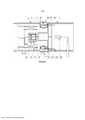
[026] A Figura 1 é um diagrama estrutural esquemático de um primeiro modelo do presente pedido, no qual uma extremidade esquerda (a) de um limitador de corrente está ligada a um primeiro condutor principal, e uma extremidade direita (b) do limitador de corrente está ligada a um dispositivo de ruptura;[026] Figure 1 is a schematic structural diagram of a first model of the present application, in which a left end (a) of a current limiter is connected to a first main conductor, and a right end (b) of the current limiter. current is connected to a breaking device;
[027] A Figura 2 é um diagrama estrutural esquemático de um segundo modelo do presente pedido, no qual uma extremidade esquerda (a) de um limitador de corrente está ligada a um dispositivo de ruptura, e uma extremidade direita (b) do limitador de corrente está ligada a um primeiro condutor principal; e[027] Figure 2 is a schematic structural diagram of a second model of the present application, in which a left end (a) of a current limiter is connected to a breaking device, and a right end (b) of the current limiter. current is connected to a first main conductor; and
[028] A Figura 3 é um diagrama estrutural esquemático de um terceiro modelo do presente pedido, no qual um contato principal de movimento, contatos principais fixos e um dispositivo de ruptura estão na mesma cavidade.[028] Figure 3 is a schematic structural diagram of a third model of the present order, in which a moving main contact, fixed main contacts and a breaking device are in the same cavity.
[029] Especificamente, 1 e 2 representam respectivamente um primeiro condutor principal e um segundo condutor principal, 3 e 3' representam respectivamente um primeiro contato principal fixo e um segundo contato principal fixo, 4 representa um contato principal de movimento anelar, 5 representa um dispositivo de ruptura com uma função de extinção de arco, 6 representa um limitador de corrente, 7 e 7' representam respectivamente um primeiro isolador e um segundo isolador, 8 representa um mecanismo de operação, 9 e 10 representam respectivamente um primeiro conector externo e um segundo conector externo, e 9’ e 10' representam respectivamente um primeiro conector interno e um segundo conector interno.[029] Specifically, 1 and 2 respectively represent a first main conductor and a second main conductor, 3 and 3' respectively represent a first fixed main contact and a second fixed main contact, 4 represents an annular movement main contact, 5 represents a breaking device with an arc extinguishing function, 6 represents a current limiter, 7 and 7' represent respectively a first insulator and a second insulator, 8 represents an operating mechanism, 9 and 10 respectively represent a first external connector and a second external connector, and 9' and 10' respectively represent a first internal connector and a second internal connector.
[030] DESCRIÇÃO DETALHADA DE VERSÕES[030] DETAILED DESCRIPTION OF VERSIONS
[031] Em seguida, o presente pedido é descrito em detalhe juntamente com os desenhos.[031] Next, the present application is described in detail together with the drawings.
[032] Relativamente à Figura 1, Figura 2 e Figura 3, um interruptor de alta potência com um limitador de corrente de acordo com o presente pedido inclui: um primeiro condutor principal 1 e um segundo condutor principal 2 dispostos respectivamente em uma seção anterior e em uma seção posterior do interruptor para conduzir uma corrente de carga, um primeiro contato principal fixo 3 e um segundo contato principal fixo 3', um contato principal de movimento 4, um primeiro conector externo 9 e um segundo conector externo 10, um primeiro conector interno 9' e um segundo conector interno 10', um dispositivo de ruptura 5 com uma função de extinção de arco, um limitador de corrente 6, um primeiro isolador 7 e um segundo isolador 7', e um mecanismo de operação 8.[032] Referring to Figure 1, Figure 2 and Figure 3, a high power switch with a current limiter according to the present application includes: a first
[033] O primeiro condutor principal 1 e o segundo condutor principal 2 estão dispostos coaxialmente. O primeiro condutor principal 1, o primeiro conector externo 9, o primeiro contato principal 3, o contato principal de movimento 4, o segundo contato principal fixo 3', o segundo conector externo 10 e o segundo condutor principal 2 estão ligados em sequência para formar um circuito condutor principal para conduzir uma corrente de carga em uma operação normal. E o contato principal de movimento 4 está ainda conectado ao mecanismo de operação 8 com uma função de comutação.[033] The first
[034] O primeiro condutor principal e o segundo condutor principal têm estruturas ocas. E o limitador de corrente 6 e o dispositivo de ruptura 5 estão dispostos dentro do primeiro condutor principal 1.[034] The first main conductor and the second main conductor have hollow structures. And the
[035] Um interruptor de circuito condutor principal é formado pelo primeiro contato principal fixo 3 e o segundo contato principal fixo 3’ juntamente com o contato principal de movimento 4, que tem uma certa resistência a uma ablação de um arco e uma certa capacidade de extinguir o arco. Um setor de extinção de arco do interruptor é formado pela ligação em série do dispositivo de ruptura 5 com uma função de extinção de arco e do limitador de corrente 6, e o dispositivo de ruptura 5 está ainda ligado ao mecanismo de operação com a função de comutação. O setor de extinção de arco está ligado em paralelo ao circuito condutor principal. E a resistência do circuito condutor principal é inferior à resistência do setor de extinção de arco.[035] A main conductive circuit breaker is formed by the first fixed
[036] O primeiro contato principal fixo 3 e o segundo contato principal fixo 3’ podem estar respectivamente dispostos no primeiro conector externo 9 e no segundo conector externo 10, e o contato principal de movimento 4 transpõe o primeiro contato principal fixo 3 e o segundo contato principal fixo 3’.[036] The first fixed
[037] Em um primeiro modelo e segundo modelo da apresentação, o primeiro conector externo 9 está ligado ao primeiro conector interno 9', o segundo conector externo 10 está ligado ao segundo conector interno 10'. O primeiro conector externo 9 está ligado ao segundo conector externo 10 através do primeiro isolador 7, o primeiro conector interno 9' está ligado ao segundo conector interno 10' através do segundo isolador 7'. Pode formar-se uma cavidade entre o primeiro conector externo 9, o segundo conector externo 10, o primeiro conector interno 9’, o segundo conector interno 10’, o primeiro isolador 7 e o segundo isolador 7’. E o primeiro contato principal fixo 3, o segundo contato principal fixo 3’ e o contato principal de movimento 4 podem estar dispostos na cavidade.[037] In a first model and second model of the presentation, the first
[038] No caso em que está selada a cavidade formada entre o primeiro conector externo 9, o segundo conector externo 9’, os primeiros conectores internos 10, o segundo conector interno 10', o primeiro isolador 7 e o segundo isolador 7', a cavidade é enchida com gás isolante, tal como o SF6.[038] In the case where the cavity formed between the first
[039] O dispositivo de ruptura 5 pode estar disposto fora do limitador de corrente, tal como se pode ver na Figura 1. Em alternativa, o dispositivo de ruptura 5 pode sobressair parcialmente ou inteiramente para uma cavidade do limitador de corrente 6, tal como se pode ver na Figura 2, o que leva a uma estrutura mais compacta do interruptor.[039] The
[040] Em um terceiro modelo, tal como se pode ver na Figura 3, o primeiro conector externo 9 está ligado ao segundo conector externo 10 através do primeiro isolador 7, o primeiro conector externo 9 está ligado ao primeiro conector interno 9' através do segundo isolador 7', a outra extremidade do primeiro conector interno 9' está ligada a um lado fixo do dispositivo de ruptura 5. O segundo conector externo 10 está diretamente ligado ao segundo conetor interno 10', e a outra extremidade do segundo conector interno 10' está ligada a um lado de movimento do dispositivo de ruptura 5. Pode formar-se uma grande cavidade entre o primeiro conector externo 9, o segundo conector externo 10, o primeiro conector interno 9’, o segundo conector interno 10’, o primeiro isolador 7 e o segundo isolador 7’. O primeiro contato principal fixo, o segundo contato principal fixo, o contato principal de movimento e o dispositivo de ruptura estão todos dispostos na cavidade. A cavidade está selada e enchida com gás isolante, tal como SF6.[040] In a third model, as can be seen in Figure 3, the first
[041] O dispositivo de ruptura 5 e o limitador de corrente 6 estão localizados dentro do condutor principal. Uma extremidade do limitador de corrente 6 está ligada ao primeiro condutor principal 1 e a outra extremidade do limitador 6 está ligada ao dispositivo de ruptura 5, e o limitador de corrente 6 está posicionado ao longo de uma linha axial do primeiro condutor principal 1. O dispositivo de ruptura 5 está ligado em série ao limitador de corrente 6 para formar o setor de extinção de arco para interromper ou conduzir uma corrente de carga e uma corrente de curto-circuito.[041]
[042] O contato principal de movimento 4 e o dispositivo de ruptura 5 ligados em paralelo ao contato principal de movimento 4 podem ser acionados pelo mesmo mecanismo de operação, tal como o mecanismo de operação 8, ou por diferentes mecanismos de operação. Em um estado condutor normal de um interruptor, o circuito condutor principal e o setor de extinção de arco estão ligados, e a corrente flui primeiramente pelo circuito condutor principal devido à menor resistência do circuito condutor principal comparativamente com a resistência do setor de extinção de arco. Em um processo de desligar o interruptor, em primeiro lugar, o circuito condutor principal é desligado pelo contato principal de movimento 4, depois a corrente é transferida para o setor de extinção de arco. E o dispositivo de ruptura 5 pode interromper suavemente uma vez que o valor numérico da corrente de curto-circuito está limitado a uma faixa aceitável devido ao limitador de corrente ligado em série ao setor de extinção de arco. O processo de corrente em um processo de ligar o interruptor é contrário ao processo de corrente no processo de desligar o interruptor: o contato no dispositivo de ruptura 5 é primeiramente ligado, depois o setor de extinção de arco conduz a corrente, e depois o circuito condutor principal é ligado pelo contato principal de movimento 4, uma vez que a corrente é transferida para o circuito condutor principal com a resistência menor.[042] The main movement contact 4 and the
[043] No dispositivo de ruptura 5 está configurada uma câmara de extinção de arco a vácuo ou uma câmara de extinção de arco de detonação a gás. No caso de a câmara de extinção de arco a vácuo estar configurada no dispositivo de ruptura 5, o mecanismo de operação que aciona o dispositivo de ruptura 5 é um mecanismo de operação por mola ou um mecanismo de operação por magnetismo permanente com uma função de seleção de fase.[043] In the
[044] Os números de índice dos modelos do presente pedido destinam-se apenas à descrição e não representam uma ordem de qualidades dos modelos. Os acima mencionados são apenas os melhores modelos do presente pedido e não pretendem limitar o presente pedido. Quaisquer modificações, substituições equivalentes, melhoramentos e idênticos feitos dentro do espírito e princípios do presente pedido inserem-se todos no âmbito de proteção do presente pedido.[044] The index numbers of the models of the present application are for description only and do not represent an order of qualities of the models. The above mentioned are only the best models of the present application and are not intended to limit the present application. Any modifications, equivalent replacements, improvements and the like made within the spirit and principles of this application all fall within the scope of protection of this application.
Claims (11)
Applications Claiming Priority (3)
| Application Number | Priority Date | Filing Date | Title |
|---|---|---|---|
| CN201410453010.0 | 2014-09-05 | ||
| CN201410453010.0A CN104269315B (en) | 2014-09-05 | 2014-09-05 | High power switch with current limiter |
| PCT/CN2015/088958 WO2016034149A1 (en) | 2014-09-05 | 2015-09-06 | High-power switch with current limiter |
Publications (2)
| Publication Number | Publication Date |
|---|---|
| BR112016014482A2 BR112016014482A2 (en) | 2017-08-08 |
| BR112016014482B1 true BR112016014482B1 (en) | 2022-03-29 |
Family
ID=52160827
Family Applications (1)
| Application Number | Title | Priority Date | Filing Date |
|---|---|---|---|
| BR112016014482-1A BR112016014482B1 (en) | 2014-09-05 | 2015-09-06 | HIGH POWER SWITCH WITH CURRENT LIMITER |
Country Status (4)
| Country | Link |
|---|---|
| CN (1) | CN104269315B (en) |
| BR (1) | BR112016014482B1 (en) |
| RU (1) | RU2660964C1 (en) |
| WO (1) | WO2016034149A1 (en) |
Families Citing this family (8)
| Publication number | Priority date | Publication date | Assignee | Title |
|---|---|---|---|---|
| CN104269315B (en) * | 2014-09-05 | 2016-09-14 | 中国西电电气股份有限公司 | High power switch with current limiter |
| US10857012B2 (en) | 2015-01-20 | 2020-12-08 | Neurogami Medical, Inc. | Vascular implant |
| CA2972620C (en) | 2015-01-20 | 2023-08-01 | Neurogami Medical, Inc. | Micrograft for the treatment of intracranial aneurysms and method for use |
| US10925611B2 (en) | 2015-01-20 | 2021-02-23 | Neurogami Medical, Inc. | Packaging for surgical implant |
| US11484319B2 (en) | 2015-01-20 | 2022-11-01 | Neurogami Medical, Inc. | Delivery system for micrograft for treating intracranial aneurysms |
| US10736730B2 (en) | 2015-01-20 | 2020-08-11 | Neurogami Medical, Inc. | Vascular implant |
| CN108878199B (en) * | 2018-07-24 | 2024-01-23 | 柳州长虹航天技术有限公司 | Press-type multi-contact switching current buffer switch |
| CN109637882A (en) * | 2018-10-25 | 2019-04-16 | 国网宁夏电力有限公司电力科学研究院 | Vacuum circuit breaker |
Family Cites Families (16)
| Publication number | Priority date | Publication date | Assignee | Title |
|---|---|---|---|---|
| US4488021A (en) * | 1981-11-12 | 1984-12-11 | Mitsubishi Denki Kabushiki Kaisha | Gas insulated disconnector |
| JPH0719504B2 (en) * | 1988-11-08 | 1995-03-06 | 三菱電機株式会社 | Disconnector |
| JPH06101276B2 (en) * | 1989-08-24 | 1994-12-12 | 三菱電機株式会社 | Disconnector |
| JPH0381919A (en) * | 1989-08-25 | 1991-04-08 | Toshiba Corp | Gas insulation switch |
| JP2586261B2 (en) * | 1991-10-22 | 1997-02-26 | 三菱電機株式会社 | Disconnector |
| DE4430579B4 (en) * | 1994-08-18 | 2005-03-31 | Siemens Ag | High voltage switch with a main switching contact and an auxiliary switching device |
| JP3202551B2 (en) * | 1995-08-08 | 2001-08-27 | 株式会社日立製作所 | Gas circuit breaker |
| FR2925755B1 (en) * | 2007-12-21 | 2012-08-03 | Schneider Electric Ind Sas | INSULATION OF VACUUM BULB TYPE CUTTING DEVICE BY OVERMOLDING |
| KR101022897B1 (en) * | 2008-12-31 | 2011-03-16 | 엘에스산전 주식회사 | Current limit apparatus and fault current limiter using the same |
| CN201773754U (en) * | 2010-08-20 | 2011-03-23 | 中国西电电气股份有限公司 | High-capacity vacuum circuit breaker for protecting short-circuit impact generator used in testing station |
| KR101115639B1 (en) * | 2010-10-18 | 2012-02-15 | 엘에스산전 주식회사 | Contact assembly for vacuum interrupter |
| KR200477244Y1 (en) * | 2011-02-22 | 2015-05-22 | 엘에스산전 주식회사 | Circuit breaker |
| CN203503542U (en) * | 2013-08-30 | 2014-03-26 | 沈阳华德海泰电子有限公司 | Double-break tank vacuum circuit breaker |
| CN103811224B (en) * | 2014-01-23 | 2017-02-15 | 天津平高智能电气有限公司 | Vacuum arc-extinguishing chamber and electrode thereof as well as contact structure |
| CN204067167U (en) * | 2014-09-05 | 2014-12-31 | 中国西电电气股份有限公司 | With the high power switch of mutual reactor |
| CN104269315B (en) * | 2014-09-05 | 2016-09-14 | 中国西电电气股份有限公司 | High power switch with current limiter |
-
2014
- 2014-09-05 CN CN201410453010.0A patent/CN104269315B/en active Active
-
2015
- 2015-09-06 RU RU2016127608A patent/RU2660964C1/en active
- 2015-09-06 WO PCT/CN2015/088958 patent/WO2016034149A1/en active Application Filing
- 2015-09-06 BR BR112016014482-1A patent/BR112016014482B1/en active IP Right Grant
Also Published As
| Publication number | Publication date |
|---|---|
| WO2016034149A1 (en) | 2016-03-10 |
| CN104269315A (en) | 2015-01-07 |
| RU2660964C1 (en) | 2018-07-11 |
| CN104269315B (en) | 2016-09-14 |
| BR112016014482A2 (en) | 2017-08-08 |
Similar Documents
| Publication | Publication Date | Title |
|---|---|---|
| BR112016014482B1 (en) | HIGH POWER SWITCH WITH CURRENT LIMITER | |
| US9837236B2 (en) | High-voltage direct-current thermal fuse | |
| BR102014010994B1 (en) | DIRECT CURRENT SWITCHING APPARATUS, ELECTRONIC DEVICE, AND METHOD FOR SWITCHING AN ASSOCIATED DIRECT CURRENT CIRCUIT | |
| US20150221464A1 (en) | Pole part of a medium voltage circuit breaker arrangement comprising a triggered gap unit | |
| BRPI0708214B1 (en) | ELECTRICAL SWITCHING DEVICE AND METHOD FOR SWITCHING AN AIR INSULATED GROUNDING SWITCH | |
| US1889585A (en) | Multiple conductor fuse | |
| CN207425786U (en) | A kind of safety device with fusing warning function | |
| CN204167901U (en) | A kind of compact high-performance lightning discharger | |
| GB730346A (en) | Improvements in electric circuit-breaker devices | |
| US2658977A (en) | Electrical load break switch | |
| CN204067167U (en) | With the high power switch of mutual reactor | |
| CN218482187U (en) | Arc extinguishing system for improving breaking capacity of circuit breaker | |
| CN109586266A (en) | A kind of safe and efficient electrical equipment high-voltage and current-limitation device | |
| CN107452551A (en) | Relay | |
| CN209591955U (en) | A kind of striking static contact and its breaker of plastic casing | |
| CN102110554B (en) | Protective device for high-voltage power equipment | |
| BR102012028980A2 (en) | device and process of protection of an electric circuit and electric contactor | |
| CN107689311A (en) | A kind of disengaged surge protective device and its application | |
| CN207097737U (en) | A kind of on-load switch of resistance to vacuum arc | |
| CN200990306Y (en) | Arc extinguish structure beneficial to arc extinction | |
| CN208208706U (en) | A kind of fuse | |
| CN208208703U (en) | A kind of fuse | |
| CN105428181A (en) | Fuse protector | |
| CN207097738U (en) | A kind of air hermetic arc extinguishing vacuum load switch | |
| CN109003871A (en) | A kind of fastp-acting fuse with prompt facility |
Legal Events
| Date | Code | Title | Description |
|---|---|---|---|
| B06U | Preliminary requirement: requests with searches performed by other patent offices: procedure suspended [chapter 6.21 patent gazette] | ||
| B09A | Decision: intention to grant [chapter 9.1 patent gazette] | ||
| B16A | Patent or certificate of addition of invention granted [chapter 16.1 patent gazette] |
Free format text: PRAZO DE VALIDADE: 20 (VINTE) ANOS CONTADOS A PARTIR DE 06/09/2015, OBSERVADAS AS CONDICOES LEGAIS. |