BR112016014297B1 - EQUIPMENT AND METHOD FOR OPTICAL TOMOGRAPHY - Google Patents
EQUIPMENT AND METHOD FOR OPTICAL TOMOGRAPHY Download PDFInfo
- Publication number
- BR112016014297B1 BR112016014297B1 BR112016014297-7A BR112016014297A BR112016014297B1 BR 112016014297 B1 BR112016014297 B1 BR 112016014297B1 BR 112016014297 A BR112016014297 A BR 112016014297A BR 112016014297 B1 BR112016014297 B1 BR 112016014297B1
- Authority
- BR
- Brazil
- Prior art keywords
- arm
- objective
- optical
- path
- line
- Prior art date
Links
Images
Classifications
-
- G—PHYSICS
- G01—MEASURING; TESTING
- G01B—MEASURING LENGTH, THICKNESS OR SIMILAR LINEAR DIMENSIONS; MEASURING ANGLES; MEASURING AREAS; MEASURING IRREGULARITIES OF SURFACES OR CONTOURS
- G01B9/00—Measuring instruments characterised by the use of optical techniques
- G01B9/02—Interferometers
-
- A—HUMAN NECESSITIES
- A61—MEDICAL OR VETERINARY SCIENCE; HYGIENE
- A61B—DIAGNOSIS; SURGERY; IDENTIFICATION
- A61B90/00—Instruments, implements or accessories specially adapted for surgery or diagnosis and not covered by any of the groups A61B1/00 - A61B50/00, e.g. for luxation treatment or for protecting wound edges
- A61B90/36—Image-producing devices or illumination devices not otherwise provided for
- A61B90/37—Surgical systems with images on a monitor during operation
-
- G—PHYSICS
- G01—MEASURING; TESTING
- G01B—MEASURING LENGTH, THICKNESS OR SIMILAR LINEAR DIMENSIONS; MEASURING ANGLES; MEASURING AREAS; MEASURING IRREGULARITIES OF SURFACES OR CONTOURS
- G01B9/00—Measuring instruments characterised by the use of optical techniques
- G01B9/02—Interferometers
- G01B9/0209—Low-coherence interferometers
- G01B9/02091—Tomographic interferometers, e.g. based on optical coherence
-
- G—PHYSICS
- G02—OPTICS
- G02B—OPTICAL ELEMENTS, SYSTEMS OR APPARATUS
- G02B21/00—Microscopes
- G02B21/0004—Microscopes specially adapted for specific applications
- G02B21/002—Scanning microscopes
- G02B21/0024—Confocal scanning microscopes (CSOMs) or confocal "macroscopes"; Accessories which are not restricted to use with CSOMs, e.g. sample holders
- G02B21/0032—Optical details of illumination, e.g. light-sources, pinholes, beam splitters, slits, fibers
-
- G—PHYSICS
- G02—OPTICS
- G02B—OPTICAL ELEMENTS, SYSTEMS OR APPARATUS
- G02B21/00—Microscopes
- G02B21/0004—Microscopes specially adapted for specific applications
- G02B21/002—Scanning microscopes
- G02B21/0024—Confocal scanning microscopes (CSOMs) or confocal "macroscopes"; Accessories which are not restricted to use with CSOMs, e.g. sample holders
- G02B21/0036—Scanning details, e.g. scanning stages
-
- G—PHYSICS
- G02—OPTICS
- G02B—OPTICAL ELEMENTS, SYSTEMS OR APPARATUS
- G02B21/00—Microscopes
- G02B21/0004—Microscopes specially adapted for specific applications
- G02B21/002—Scanning microscopes
- G02B21/0024—Confocal scanning microscopes (CSOMs) or confocal "macroscopes"; Accessories which are not restricted to use with CSOMs, e.g. sample holders
- G02B21/0052—Optical details of the image generation
- G02B21/0056—Optical details of the image generation based on optical coherence, e.g. phase-contrast arrangements, interference arrangements
-
- G—PHYSICS
- G02—OPTICS
- G02B—OPTICAL ELEMENTS, SYSTEMS OR APPARATUS
- G02B21/00—Microscopes
- G02B21/0004—Microscopes specially adapted for specific applications
- G02B21/002—Scanning microscopes
- G02B21/0024—Confocal scanning microscopes (CSOMs) or confocal "macroscopes"; Accessories which are not restricted to use with CSOMs, e.g. sample holders
- G02B21/0052—Optical details of the image generation
- G02B21/0064—Optical details of the image generation multi-spectral or wavelength-selective arrangements, e.g. wavelength fan-out, chromatic profiling
-
- G—PHYSICS
- G02—OPTICS
- G02B—OPTICAL ELEMENTS, SYSTEMS OR APPARATUS
- G02B21/00—Microscopes
- G02B21/0004—Microscopes specially adapted for specific applications
- G02B21/002—Scanning microscopes
- G02B21/0024—Confocal scanning microscopes (CSOMs) or confocal "macroscopes"; Accessories which are not restricted to use with CSOMs, e.g. sample holders
- G02B21/008—Details of detection or image processing, including general computer control
-
- G—PHYSICS
- G02—OPTICS
- G02B—OPTICAL ELEMENTS, SYSTEMS OR APPARATUS
- G02B21/00—Microscopes
- G02B21/33—Immersion oils, or microscope systems or objectives for use with immersion fluids
-
- G—PHYSICS
- G02—OPTICS
- G02B—OPTICAL ELEMENTS, SYSTEMS OR APPARATUS
- G02B21/00—Microscopes
- G02B21/36—Microscopes arranged for photographic purposes or projection purposes or digital imaging or video purposes including associated control and data processing arrangements
- G02B21/365—Control or image processing arrangements for digital or video microscopes
- G02B21/367—Control or image processing arrangements for digital or video microscopes providing an output produced by processing a plurality of individual source images, e.g. image tiling, montage, composite images, depth sectioning, image comparison
-
- G—PHYSICS
- G06—COMPUTING; CALCULATING OR COUNTING
- G06T—IMAGE DATA PROCESSING OR GENERATION, IN GENERAL
- G06T7/00—Image analysis
- G06T7/0002—Inspection of images, e.g. flaw detection
- G06T7/0012—Biomedical image inspection
-
- A—HUMAN NECESSITIES
- A61—MEDICAL OR VETERINARY SCIENCE; HYGIENE
- A61B—DIAGNOSIS; SURGERY; IDENTIFICATION
- A61B90/00—Instruments, implements or accessories specially adapted for surgery or diagnosis and not covered by any of the groups A61B1/00 - A61B50/00, e.g. for luxation treatment or for protecting wound edges
- A61B90/36—Image-producing devices or illumination devices not otherwise provided for
- A61B90/37—Surgical systems with images on a monitor during operation
- A61B2090/373—Surgical systems with images on a monitor during operation using light, e.g. by using optical scanners
- A61B2090/3735—Optical coherence tomography [OCT]
-
- G—PHYSICS
- G06—COMPUTING; CALCULATING OR COUNTING
- G06T—IMAGE DATA PROCESSING OR GENERATION, IN GENERAL
- G06T2207/00—Indexing scheme for image analysis or image enhancement
- G06T2207/10—Image acquisition modality
- G06T2207/10072—Tomographic images
-
- G—PHYSICS
- G06—COMPUTING; CALCULATING OR COUNTING
- G06T—IMAGE DATA PROCESSING OR GENERATION, IN GENERAL
- G06T2207/00—Indexing scheme for image analysis or image enhancement
- G06T2207/30—Subject of image; Context of image processing
- G06T2207/30004—Biomedical image processing
Landscapes
- Physics & Mathematics (AREA)
- General Physics & Mathematics (AREA)
- Chemical & Material Sciences (AREA)
- Engineering & Computer Science (AREA)
- Analytical Chemistry (AREA)
- Optics & Photonics (AREA)
- Health & Medical Sciences (AREA)
- Nuclear Medicine, Radiotherapy & Molecular Imaging (AREA)
- Radiology & Medical Imaging (AREA)
- General Health & Medical Sciences (AREA)
- Computer Vision & Pattern Recognition (AREA)
- Surgery (AREA)
- Medical Informatics (AREA)
- Life Sciences & Earth Sciences (AREA)
- Multimedia (AREA)
- Theoretical Computer Science (AREA)
- Veterinary Medicine (AREA)
- Heart & Thoracic Surgery (AREA)
- Animal Behavior & Ethology (AREA)
- Oral & Maxillofacial Surgery (AREA)
- Public Health (AREA)
- Pathology (AREA)
- Gynecology & Obstetrics (AREA)
- Molecular Biology (AREA)
- Spectroscopy & Molecular Physics (AREA)
- General Engineering & Computer Science (AREA)
- Quality & Reliability (AREA)
- Biomedical Technology (AREA)
- Oil, Petroleum & Natural Gas (AREA)
- Microscoopes, Condenser (AREA)
- Investigating Or Analysing Materials By Optical Means (AREA)
- Ophthalmology & Optometry (AREA)
Abstract
aparelho e método para tomografia óptica. aparelho de tomografia óptica compreendendo: uma fonte de luz policromática (slm), um sensor óptico unidimensional (cim), um microscópio interferométrico (mi), um sistema de filtragem espacial confocal unidimensional (fs), um sistema de acionamento (pr, tr1, tr2, tr3) que permite realizar uma varredura unidirecional em profundidade de um objeto a observar e um processador (pr) para reconstituir uma imagem bidimensional de uma seção do referido objeto a partir de uma pluralidade de imagens de interferências unidimensionais adquiridas pelo referido sensor de imagem no decurso da referida varredura unidirecional. processo de tomografia óptica através da utilização de um tal aparelho.apparatus and method for optical tomography. optical tomography apparatus comprising: a polychromatic light source (slm), a one-dimensional optical sensor (cim), an interferometric microscope (mi), a one-dimensional confocal spatial filtering system (fs), a drive system (pr, tr1, tr2, tr3) which makes it possible to perform a unidirectional in-depth scan of an object to be observed and a processor (pr) to reconstitute a two-dimensional image of a section of said object from a plurality of one-dimensional interference images acquired by said image sensor during the said unidirectional scan. optical tomography process using such an apparatus.
Description
[001] A presente invenção refere-se a um método e a um aparelho de tomografia óptica, destinados em particular, mas não exclusivamente, a aplicações biológicas e médicas, incluindo histológicas. Outras aplicações possíveis incluem, por exemplo, a caracterização de materiais.[001] The present invention relates to an optical tomography method and apparatus, intended in particular, but not exclusively, for biological and medical, including histological, applications. Other possible applications include, for example, the characterization of materials.
[002] O exame histológico de tecidos recolhidos por biópsia apresenta uma grande utilidade na prática clínica, por exemplo, para o diagnóstico de tumores. No entanto, esta técnica é de realização lenta e complexa, porque requer uma biópsia, ou seja, a recolha de uma amostra do tecido a estudar, e seu corte em finas tranches que são observadas ao microscópio e analisadas por um anatomopatologista. O procedimento completo requer, além disso, a fixação da amostra, a sua oclusão em uma matriz e a sua coloração. Isto levanta problemas, sobretudo no caso de exames praticados durante operações cirúrgicas, onde a rapidez tem uma importância primordial. Além disso, a etapa de obtenção pode ser prejudicial, mesmo perigosa, para o paciente (caso do cérebro, por exemplo). Por este motivo, foram desenvolvidas técnicas de imagiologia não intrusivas - designadamente ópticas - para visualizar a estrutura interna dos tecidos biológicos - ou mais geralmente de objetos semitransparentes. Para poderem ser competi-tivas com os exames histológicos convencionais, estas técnicas devem permitir aceder in situ a uma profundidade da ordem do milímetro sob a superfície do tecido e apresentar uma resolução da ordem do micrómetro. A rapidez de execução, a simplicidade e o custo são igualmente parâmetros importantes a ter em conta.[002] The histological examination of tissues collected by biopsy is very useful in clinical practice, for example, for the diagnosis of tumors. However, this technique is slow and complex to perform, because it requires a biopsy, that is, the collection of a sample of the tissue to be studied, and its cutting into thin tranches that are observed under a microscope and analyzed by an anatomopathologist. The complete procedure also requires fixation of the sample, its occlusion in a matrix and its staining. This raises problems, especially in the case of examinations carried out during surgical operations, where speed is of paramount importance. Furthermore, the acquisition step can be harmful, even dangerous, for the patient (in the case of the brain, for example). For this reason, non-intrusive imaging techniques - namely optical - have been developed to visualize the internal structure of biological tissues - or more generally of semi-transparent objects. In order to be competitive with conventional histological examinations, these techniques must allow in situ access to a depth of the order of a millimeter under the tissue surface and have a resolution of the order of a micrometer. Speed of execution, simplicity and cost are also important parameters to take into account.
[003] Nenhuma das técnicas de imagiologia conhecidas do estado da técnica proporciona completa satisfação.[003] None of the imaging techniques known from the prior art provide complete satisfaction.
[004] A tomografia por coerência óptica (OCT, do inglês «Optical Coherence Tomography») de varredura é uma técnica baseada na in- terferometria em luz «branca» (de banda larga). Na sua versão no domínio temporal, um feixe de luz branca é dividido em duas partes, uma focalizada sobre o tecido a estudar e a outra em um espelho de referência. A luz refletida (retrodifundida) pelo objeto observado é combi-nada com a refletida pelo espelho de referência e detectada por um fotodetector. Somente é produzida uma interferência quando a diferença de caminho óptico é, no máximo, da ordem do comprimento de coerência da radiação; modificando o comprimento óptico do braço de referência do interferômetro se acede a profundidades diferentes no objeto. Uma imagem a 2 ou mesmo 3 dimensões pode ser construída graças à interferometria (que permite a aquisição segundo a dimensão axial, ou seja a profundidade) e à varredura (que permite a aquisição segundo uma ou duas dimensões laterais). Na OCT de varredura no domínio frequencial, o braço de referência tem um comprimento óptico fixo e o sinal interferométrico é analisado espectralmente. Ver a este respeito o artigo de A. F. Fercher «Optical coherence tomography - principles and applications», Reports on Progress, in Physics 66 (2003) 239 - 303. Na prática, a OCT dificilmente permite obter resoluções laterais maiores do que cerca de alguns micrómetros.[004] Optical Coherence Tomography (OCT) scanning is a technique based on “white” (broadband) light interferometry. In its version in the temporal domain, a beam of white light is divided into two parts, one focused on the tissue to be studied and the other on a reference mirror. The light reflected (backscattered) by the observed object is combined with that reflected by the reference mirror and detected by a photodetector. Interference is only produced when the optical path difference is at most on the order of the radiation coherence length; modifying the optical length of the reference arm of the interferometer accesses different depths in the object. An image in 2 or even 3 dimensions can be constructed thanks to interferometry (which allows acquisition according to the axial dimension, ie depth) and scanning (which allows acquisition in one or two lateral dimensions). In frequency domain scanning OCT, the reference arm has a fixed optical length and the interferometric signal is analyzed spectrally. See in this regard the article by AF Fercher «Optical coherence tomography - principles and applications», Reports on Progress, in Physics 66 (2003) 239 - 303. In practice, OCT hardly allows to obtain lateral resolutions greater than about a few micrometers. .
[005] Uma técnica mais recente, a OCT de campo aberto, utiliza um sensor bidimensional de imagens para detectar os sinais interfe- rométricos. Esta técnica, combinada com a utilização de uma fonte de luz de pouca coerência temporal e espacial, tal como uma lâmpada de halogênio, permite melhorar sensivelmente a resolução espacial - tanto lateral como em profundidade (axial) - em relação à OCT de varredura. Todavia, esta técnica é pouco adaptada às aplicações nas quais o objeto é suscetível de mover-se (em particular para as aplicações in vivo), provocando então uma interferência dos sinais interferométricos. Além disso, fornece cortes «en face» (paralelos à superfície do objeto observado), enquanto que cortes verticais são muitas vezes mais úteis. Além disso, sua profundidade de penetração é menor do que em OCT de varredura. Esta técnica é descrita, por exemplo, no documento EP1364181 e no artigo de A. Dubois, K. Grieve, G. Moneron, R. Le- caque, L. Vabre, e A.C. Boccara «Ultrahigh-resolution full-field optical coherence tomography», Applied Optics 43, p. 2874 (2004).[005] A more recent technique, open field OCT, uses a two-dimensional image sensor to detect interferometric signals. This technique, combined with the use of a light source with little temporal and spatial coherence, such as a halogen lamp, allows to significantly improve the spatial resolution - both laterally and in depth (axial) - in relation to scanning OCT. However, this technique is poorly adapted to applications in which the object is likely to move (particularly for in vivo applications), causing interference from the interferometric signals. In addition, it provides «en face» cuts (parallel to the surface of the observed object), while vertical cuts are often more useful. In addition, its penetration depth is less than in scanning OCT. This technique is described, for example, in EP1364181 and in the article by A. Dubois, K. Grieve, G. Moneron, R. Lecaque, L. Vabre, and A.C. Boccara «Ultrahigh-resolution full-field optical coherence tomography», Applied Optics 43, p. 2874 (2004).
[006] O artigo de S. Kim e al. «Simultaneous measurement of refractive index and thickness by combining low-coherence interferometry and confocal optics», Optics Express, Vol. 16, No. 8, 5516 (14 de abril de 2008) descreve um processo que combina óptica confocal e interferometria de pouco comprimento de coerência para caracterizar uma amostra determinando sua espessura e seu índice de refração. Não se trata de um processo de imagiologia, menos ainda de tomogra- fia.[006] The article by S. Kim et al. «Simultaneous measurement of refractive index and thickness by combining low-coherence interferometry and confocal optics», Optics Express, Vol. 16, No. 8, 5516 (April 14, 2008) describes a process that combines confocal optics and short coherence-length interferometry to characterize a sample by determining its thickness and refractive index. It is not an imaging process, even less a tomography process.
[007] A microscopia confocal utiliza uma filtragem espacial para selecionar a luz proveniente de uma pequena região do objeto observado; uma imagem bi ou tridimensional pode então ser reconstituída por varredura. O documento EP 2 447 754 descreve um dispositivo e um processo de microscopia confocal cromática de ranhuras. Este sistema requer: - uma iluminação em luz polarizada - uma objetiva apresentando fortes aberrações cromáticas; e - um espectrômetro para medir o espectro da luz à saída do microscópio, esta medição permitindo aceder à profundidade sondada no objeto.[007] Confocal microscopy uses spatial filtering to select the light coming from a small region of the observed object; a two- or three-dimensional image can then be reconstructed by scanning. EP 2 447 754 describes a chromatic confocal groove microscopy device and method. This system requires: - illumination in polarized light - an objective showing strong chromatic aberrations; and - a spectrometer to measure the spectrum of light exiting the microscope, this measurement allowing access to the depth probed in the object.
[008] Neste dispositivo, o papel das ranhuras é gerar linhas espectrais (em que a sua largura define a resolução espectral e, portanto, a resolução espacial segundo a profundidade no objeto). Não têm um papel de filtragem confocal.[008] In this device, the role of the grooves is to generate spectral lines (in which their width defines the spectral resolution and, therefore, the spatial resolution according to the depth in the object). They do not have a confocal filtering role.
[009] O documento EP 1 586 931 descreve um outro dispositivo e processo de microscopia confocal de ranhura, que simplifica o processo de reconstrução de imagens permitindo a aquisição simultânea de vários pixels dispostos segundo uma linha. A microscopia confocal, utilizada sem marcadores fluorescentes, oferece uma profundidade de penetração sensivelmente menor do que em OCT de varredura e em OCT de campo aberto.[009] EP 1 586 931 describes another device and method of confocal slit microscopy, which simplifies the image reconstruction process by allowing the simultaneous acquisition of several pixels arranged in a line. Confocal microscopy, used without fluorescent markers, offers a significantly lower depth of penetration than scanning OCT and open-field OCT.
[0010] O artigo de Yu Chen e al. «High-resolution line-scanning optical coherence microscopy», Optics Letters Vol. 32, No. 14, 15 de julho de 2007, páginas 1971 - 1973 descreve um aparelho e um processo em que se combina microscopia confocal de ranhura e OCT de varredura que permite obter cortes «en face» de uma amostra com uma sensibilidade mais elevada do que em OCT de campo aberto. A resolução axial alcançada é de cerca de 3 μm e a resolução lateral de cerca de 2 μm, sendo estes resultados obtidos utilizando como fonte de luz um laser de pulsos femtosegundos muito dispendioso.[0010] The article by Yu Chen et al. «High-resolution line-scanning optical coherence microscopy», Optics Letters Vol. 32, No. 14, July 15, 2007, pages 1971 - 1973 describes an apparatus and a process in which confocal slit microscopy and scanning OCT are combined to obtain "en face" sections of a sample with a higher sensitivity than in OCT. open field. The axial resolution achieved is around 3 μm and the lateral resolution is around 2 μm, these results being obtained using a very expensive femtosecond pulse laser as a light source.
[0011] As técnicas de microscopia não linear (microscopia de dois fotões, por geração de harmônica...) apresentam desempenhos - em termos de profundidade de penetração, resolução espacial e cadência de aquisição - comparáveis às da OCT de campo aberto, mas isso implica um custo mais elevado e tempos de aquisição geralmente mais longos.[0011] Non-linear microscopy techniques (two-photon microscopy, harmonic generation...) present performances - in terms of penetration depth, spatial resolution and acquisition cadence - comparable to those of open field OCT, but this implies a higher cost and generally longer acquisition times.
[0012] O custo e a complexidade de realização estão igualmente entre os principais inconvenientes das técnicas de imagiologia não ópticas, tais como a microtomografia X (que apresenta igualmente uma fraca cadência de aquisição) e a imagiologia por ressonância magnética IRM (cuja resolução espacial é medíocre comparada com os métodos ópticos).[0012] The cost and complexity of implementation are also among the main drawbacks of non-optical imaging techniques, such as X-microtomography (which also has a low acquisition rate) and MRI magnetic resonance imaging (whose spatial resolution is mediocre compared to optical methods).
[0013] A invenção tem por objetivo ultrapassar pelo menos alguns dos inconvenientes anteriormente citados do estado da técnica. Mais particularmente tem por objetivo fornecer uma técnica de visualização da estrutura interna de objetos semitransparentes, tais como tecidos biológicos que permite obter cortes verticais (ortogonais à superfície do objeto) a uma cadência elevada (vários cortes por segundo), com uma alta resolução espacial (da ordem de 1 μm, tanto axialmente como lateralmente) e uma profundidade de penetração satisfatória (da ordem do milímetro). A invenção tem igualmente por objetivo fornecer uma técnica adaptada às aplicações in vivo e in situ.[0013] The invention aims to overcome at least some of the aforementioned drawbacks of the state of the art. More particularly, it aims to provide a technique for visualizing the internal structure of semi-transparent objects, such as biological tissues, which makes it possible to obtain vertical sections (orthogonal to the surface of the object) at a high rate (several slices per second), with a high spatial resolution ( of the order of 1 μm, both axially and laterally) and a satisfactory penetration depth (on the order of a millimeter). The invention also aims to provide a technique adapted to in vivo and in situ applications.
[0014] Um objeto da invenção que permite atingir este objetivo é um aparelho de tomografia óptica compreendendo: uma fonte de luz policromática; um sensor óptico unidimensional; um microscópio inter- ferométrico compreendendo: um primeiro braço, chamado de referência, na extremidade do qual é disposto um espelho chamado de referência; um segundo braço, chamado objeto; um separador de feixe acoplando o primeiro e o segundo braços à referida fonte de luz poli-cromática e ao referido sensor; e pelo menos uma objetiva, o referido espelho de referência sendo disposto em correspondência com um plano de focagem da referida objetiva ou de uma das objetivas colocadas no braço de referência; um sistema de filtragem espacial confocal unidimensional, cooperando com a referida fonte de luz policromática para iluminar um objeto a observar, disposto na extremidade do referido braço objeto, segundo uma linha, chamada linha de observação, situada no referido plano de focagem da referida objetiva ou de uma das objetivas colocadas no braço objeto, o referido sistema de filtragem espacial confocal unidimensional sendo igualmente disposto para selecionar a luz retrodifundida pelo referido objeto e proveniente da referida linha de observação, e para formar uma imagem unidimensional da referida linha no referido sensor; caracterizado por compreender igualmente: um sistema de acionamento configurado para deslocar a referida linha de observação paralelamente a um eixo óptico da referi- da objetiva ou de uma das objetivas colocadas no braço objeto de modo a realizar uma varredura unidirecional do referido objeto, ao mesmo tempo que mantem uma diferença de caminho óptico nula entre, por um lado, um primeiro trajeto que vai do referido separador de feixe ao referido espelho de referência e regressa percorrendo o referido braço de referência e, por outro lado, um segundo trajeto que vai do referido separador de feixe na referida linha de observação e regressa percorrendo o referido braço objeto; e um processador programado ou configurado para reconstituir uma imagem bidimensional de uma seção do referido objeto a observar, orientada paralelamente ao referido eixo óptico da referida objetiva ou de uma das objetivas colocadas no braço objeto, a partir de uma pluralidade de imagens interferométricas unidimensionais adquiridas pelo referido sensor em correspondência com posições diferentes da referida linha de observação no decurso da referida varredura unidirecional.[0014] An object of the invention that allows achieving this objective is an optical tomography apparatus comprising: a polychromatic light source; a one-dimensional optical sensor; an interferometric microscope comprising: a first arm, called a reference, at the end of which a mirror called a reference is arranged; a second arm, called an object; a beam splitter coupling first and second arms to said polychromatic light source and said sensor; and at least one objective, said reference mirror being arranged in correspondence with a plane of focus of said objective or of one of the objectives placed on the reference arm; a one-dimensional confocal spatial filtering system, cooperating with said polychromatic light source to illuminate an object to be observed, disposed at the end of said object arm, along a line, called the observation line, situated in said focusing plane of said objective, or from one of the objectives placed on the object arm, said one-dimensional confocal spatial filtering system also being arranged to select light backscattered by said object from said line of sight, and to form a one-dimensional image of said line on said sensor; characterized in that it also comprises: a drive system configured to move said observation line parallel to an optical axis of said objective or of one of the objectives placed on the object arm in order to perform a unidirectional scan of said object, at the same time which maintains a zero optical path difference between, on the one hand, a first path that goes from said beam splitter to said reference mirror and returns along said reference arm and, on the other hand, a second path that goes from said beam splitter at said observation line and returns along said object arm; and a processor programmed or configured to reconstitute a two-dimensional image of a section of said object to be observed, oriented parallel to said optical axis of said objective or of one of the objectives placed on the object arm, from a plurality of one-dimensional interferometric images acquired by the said sensor in correspondence with different positions of said observation line in the course of said unidirectional scan.
[0015] De acordo com diferentes modalidades de um tal aparelho: - O referido sistema de acionamento pode ser configurado para provocar um deslocamento relativo, paralelo ao referido eixo óptico da referida objetiva, ou de uma das objetivas colocadas no braço objeto, do referido objeto a observar em relação ao referido microscópio interferométrico, sem modificar os comprimentos ópticos do referido braço de referência e do referido braço objeto. - O referido sistema de acionamento pode ser configurado para deslocar a objetiva em cujo plano de focagem se encontra a referida linha de observação e para modificar o comprimento óptico do referido braço de referência de maneira a manter nula a diferença de caminho óptico entre o referido primeiro trajeto e o referido segundo trajeto. - O aparelho pode compreender igualmente um dispositivo de compensação da dispersão disposto em pelo menos um do referido braço objeto e do referido braço de referência, o referido sistema de acionamento sendo configurado para atuar igualmente sobre o referido dispositivo de compensação da dispersão no decurso da referida varredura unidirecional. - O referido microscópio interferométrico pode ser um microscópio de Linnik, compreendendo uma primeira objetiva disposta sobre o referido braço de referência e uma segunda objetiva disposta sobre o referido braço objeto, os referidos braço de referência e objeto sendo disjuntos. Em alternativa, pode ser escolhido entre um microscópio de Michelson e um microscópio de Mirau, compreendendo uma única objetiva.[0015] According to different modalities of such an apparatus: - Said drive system can be configured to cause a relative displacement, parallel to said optical axis of said objective, or of one of the objectives placed on the object arm, of said object to be observed with respect to said interferometric microscope, without modifying the optical lengths of said reference arm and said object arm. - Said drive system can be configured to move the objective whose focus plane is said observation line and to modify the optical length of said reference arm in such a way as to maintain zero the optical path difference between said first path and said second path. - The apparatus may also comprise a dispersion compensation device arranged on at least one of said object arm and said reference arm, said drive system being configured to also act on said dispersion compensation device during the course of said unidirectional scan. - Said interferometric microscope may be a Linnik microscope, comprising a first objective arranged on said reference arm and a second objective arranged on said object arm, said reference arm and object being disjoint. Alternatively, it can be chosen between a Michelson microscope and a Mirau microscope, comprising a single objective.
[0016] Um outro objeto da invenção é um processo de tomografia óptica compreendendo as seguintes etapas:[0016] Another object of the invention is an optical tomography process comprising the following steps:
[0017] obter uma fonte de luz policromática;[0017] obtain a polychromatic light source;
[0018] utilizar um separador de feixe para direcionar uma primeira fração de luz emitida pela referida fonte seguindo um primeiro trajeto, chamado trajeto de referência, e uma segunda fração de luz emitida pela referida fonte seguindo um segundo trajeto, chamado trajeto objeto;[0018] use a beam splitter to direct a first fraction of light emitted by said source following a first path, called reference path, and a second fraction of light emitted by said source following a second path, called object path;
[0019] utilizar uma objetiva que coopera com um sistema de filtragem espacial confocal unidimensional para focalizar a referida segunda fração de luz de modo a iluminar um objeto semitransparente a observar segundo uma linha, chamada linha de observação, situada em um plano de focagem da referida objetiva, e para recolher a luz retrodi- fundida pelo referido objeto assim iluminado;[0019] use an objective that cooperates with a one-dimensional confocal spatial filtering system to focus said second fraction of light in order to illuminate a semi-transparent object to be observed along a line, called observation line, located in a focusing plane of said objective, and to collect the light backscattered by said object thus illuminated;
[0020] utilizar a referida objetiva, ou uma outra objetiva, para focalizar a referida primeira fração de luz sobre um espelho de referência disposto sobre o referido trajeto de referência, e para recolher a luz refletida pelo referido espelho;[0020] using said objective, or another objective, to focus said first fraction of light onto a reference mirror disposed on said reference path, and to collect light reflected from said mirror;
[0021] utilizar o referido separador de feixe para combinar a luz retrodifundida pelo referido objeto com a luz refletida pelo referido espelho e direcioná-la para um sensor óptico unidimensional;[0021] use said beam splitter to combine light backscattered by said object with light reflected from said mirror and direct it to a one-dimensional optical sensor;
[0022] utilizar o referido sistema de filtragem espacial confocal unidimensional para selecionar a luz proveniente da referida linha de observação, e para formar uma imagem unidimensional no referido sensor;[0022] using said one-dimensional confocal spatial filtering system to select light from said line of sight, and to form a one-dimensional image on said sensor;
[0023] utilizar um sistema de acionamento para deslocar a referida linha de observação paralelamente a um eixo óptico da referida objetiva de maneira a realizar uma varredura unidirecional de um objeto a observar sobre o referido trajeto objeto, ao mesmo tempo que mantém uma diferença de caminho óptico nula entre o referido trajeto de referência e o referido trajeto objeto; e[0023] use a drive system to move said observation line parallel to an optical axis of said objective in order to perform a unidirectional scan of an object to be observed on said object path, while maintaining a path difference optical null between said reference path and said object path; and
[0024] utilizar um processador para reconstituir uma imagem bidimensional de uma seção do referido objeto a observar, orientada paralelamente ao referido eixo óptico, a partir de uma pluralidade de imagens interferométricas unidimensionais adquiridas pelo referido sensor em correspondência com posições diferentes da referida linha de observação no decurso da referida varredura unidirecional.[0024] use a processor to reconstitute a two-dimensional image of a section of said object to be observed, oriented parallel to said optical axis, from a plurality of one-dimensional interferometric images acquired by said sensor in correspondence with different positions of said line of observation during the said unidirectional scan.
[0025] De acordo com diferentes modalidades de um tal processo: - A referida etapa g) pode ser realizada provocando um deslocamento relativo, paralelo ao referido eixo óptico, do referido objeto a observar em relação ao referido microscópio interferométrico sem modificar os comprimentos ópticos do referido braço de referência e do referido braço objeto. - Alternativamente, a referida etapa g) pode ser realizada deslocando a objetiva em um plano focal da qual se encontra a referida linha de observação e modificando o comprimento óptico do referido braço de referência de maneira a manter nula a diferença de caminho óptico entre o referido primeiro trajeto e o referido segundo trajeto. - O processo pode compreender igualmente uma etapa i) de compensação das modificações da dispersão induzidas pelo deslo-camento da linha de observação no interior do referido objeto a observar no decurso da referida varredura unidirecional.[0025] According to different modalities of such a process: - Said step g) can be performed causing a relative displacement, parallel to said optical axis, of said object to be observed in relation to said interferometric microscope without modifying the optical lengths of the said reference arm and said object arm. - Alternatively, said step g) can be performed by moving the objective in a focal plane from which said observation line is located and modifying the optical length of said reference arm so as to keep the optical path difference between said first path and said second path. - The process may also comprise a step i) of compensating for changes in the dispersion induced by the displacement of the observation line within said object to be observed during the course of said unidirectional scan.
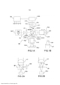
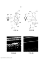
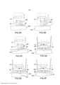
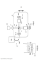
[0026] Outras características, detalhes e vantagens da invenção ressaltarão da leitura da descrição feita em referência aos desenhos anexos dados a título de exemplo e que representam, respectivamente: - A figura 1A, um esquema de princípio de um aparelho de tomografia óptica de acordo com uma modalidade da invenção, baseada em um microscópio interferométrico de Linnik; - A figura 1B, um detalhe de um aparelho de tomografia óptica de acordo com uma alternativa da referida modalidade da invenção; - As figuras 2A, 2B, outras modalidades possíveis da invenção baseadas nas configurações de microscópios interferométricos de Michelson e de Mirau; - As figuras 3A e 3B, o princípio da filtragem confocal de ranhura; - As figuras 4A e 4B, respectivamente, uma imagem obtida utilizando um aparelho de tomografia por coerência óptica de acordo com o estado da técnica e uma imagem do mesmo objeto obtida utilizando um aparelho de tomografia óptica de acordo com a invenção; - As figuras 5A a 5G, diferentes modalidades da invenção baseadas em microscópios interferométricos de Michelson e de Mirau e que utilizam um meio de imersão; e - A figura 6, uma outra modalidade da invenção baseada em um microscópio interferométrico de Linnik e que utiliza um meio de imersão.[0026] Other features, details and advantages of the invention will emerge from reading the description made with reference to the attached drawings given by way of example and which represent, respectively: - Figure 1A, a schematic of principle of an optical tomography apparatus according to with an embodiment of the invention, based on a Linnik interferometric microscope; - Figure 1B, a detail of an optical tomography apparatus according to an alternative of said embodiment of the invention; - Figures 2A, 2B, other possible embodiments of the invention based on the Michelson and Mirau interferometric microscope configurations; - Figures 3A and 3B, the principle of slot confocal filtering; - Figures 4A and 4B, respectively, an image obtained using an optical coherence tomography device according to the state of the art and an image of the same object obtained using an optical tomography device according to the invention; - Figures 5A to 5G, different embodiments of the invention based on Michelson and Mirau interferometric microscopes and using an immersion medium; and - Figure 6, another embodiment of the invention based on a Linnik interferometric microscope and using an immersion means.
[0027] A figura 1A ilustra um aparelho de tomografia óptica de acordo com a modalidade da invenção. Este aparelho é essencialmen- te constituído por um microscópio interferométrico «de Linnik» modificado pelo acrescento de meios de filtragem espacial (FE, FS), um sistema de compensação (DCD) dos espaçamentos de dispersão entre os dois braços do interferômetro, um sensor óptico unidimensional (CIM) e um processador devidamente programado ou configurado (PR).[0027] Figure 1A illustrates an optical tomography apparatus according to the embodiment of the invention. This apparatus essentially consists of a Linnik interferometric microscope modified by the addition of spatial filtering means (FE, FS), a compensation system (DCD) for the scattering spacings between the two arms of the interferometer, an optical sensor one-dimensional (CIM) and a properly programmed or configured (PR) processor.
[0028] Este aparelho compreende uma fonte de luz policromática SLP. Esta última é representada esquematicamente por uma ampola incandescente, mas poderá tratar-se, de preferência, de uma fonte de luminância mais elevada, tal como um díodo eletroluminescente ou uma associação de díodos eletroluminescentes, de um díodo super luminescente ou de uma associação de díodos super luminescentes, de uma lâmpada de filamento de halogêneo, de uma lâmpada de arco, mesmo de uma fonte laser ou à base de laser (fonte por geração de «supercontínuo», por exemplo). Em todos os casos, a sua largura espectral (a meia altura) será, de preferência, superior ou igual a 100 nm; quanto maior for esta largura espectral, melhor poderá ser a resolução axial do aparelho; o comprimento de onda de centro-banda pode ser visível ou se situar no infravermelho próximo; nas aplicações biológicas e médicas prefere-se geralmente o infravermelho próximo, entre 600 nm e 1500 nm. A fonte pode ser polarizada ou não polarizada, espacialmente coerente ou incoerente. As fontes espacialmente coerentes (do tipo lasers ou díodos super luminescentes) podem ser vantajosas em função da sua maior luminância, mas podem introduzir «ruído» de coerência: fenómenos de interferências parasitas acarretando uma redução da amplitude relativa do sinal interferométrico útil e uma falta de uniformidade da iluminação. Além disso, a utilização de fontes es-pacialmente coerentes aumenta sensivelmente o custo global do aparelho.[0028] This apparatus comprises an SLP polychromatic light source. The latter is schematically represented by an incandescent light bulb, but it could preferably be a higher luminance source, such as an electroluminescent diode or a combination of light emitting diodes, a super luminescent diode or a combination of diodes super luminescent lamps, from a halogen filament lamp, from an arc lamp, whether or not from a laser or laser-based source (source by generation of 'supercontinuous', for example). In all cases, its spectral width (at half height) will preferably be greater than or equal to 100 nm; the greater this spectral width, the better the axial resolution of the device; the center-band wavelength may be visible or in the near-infrared; in biological and medical applications near infrared, between 600 nm and 1500 nm is generally preferred. The source can be polarized or non-polarized, spatially coherent or incoherent. Spatially coherent sources (such as lasers or super luminescent diodes) can be advantageous due to their higher luminance, but they can introduce coherence "noise": stray interference phenomena leading to a reduction in the relative amplitude of the useful interferometric signal and a lack of lighting uniformity. Furthermore, the use of spatially coherent sources significantly increases the overall cost of the apparatus.
[0029] Uma ranhura FE e uma lente LE formam um sistema óptico de iluminação que coopera com a fonte SLP e com o microscópio in- terferométrico para iluminar um objeto OBJ a observar seguindo uma linha. Se a fonte de luz policromática for espacialmente coerente, a ranhura FE pode ser substituída por uma óptica de formatação de feixe, incorporando, por exemplo, uma lente cilíndrica, convergente ou divergente, para iluminar o objeto segundo uma linha da ordem do mi- crómetro (mais precisamente a largura da linha é da ordem de grandeza da resolução lateral do sistema de imagiologia).[0029] An FE slot and an LE lens form an optical illumination system that cooperates with the SLP source and the interferometric microscope to illuminate an OBJ object to be observed along a line. If the polychromatic light source is spatially coherent, the FE slot can be replaced by beamforming optics, incorporating, for example, a cylindrical lens, converging or diverging, to illuminate the object along a micrometer line. (more precisely, the width of the line is of the order of magnitude of the lateral resolution of the imaging system).
[0030] O feixe de iluminação formado pela lente LE é direcionado para um separador de feixe - no caso, um cubo separador - SF. Este último direciona uma primeira porção do feixe incidente ao longo de um primeiro braço do microscópio interferométrico, chamado «braço de referência», BREF e uma segunda porção do feixe incidente seguindo um segundo braço BOBJ, chamado «braço objeto». Uma primeira objetiva de microscópio LO1 e um espelho chamado «de referência» MR são dispostos sobre o braço de referência; a objetiva focaliza a luz sobre o espelho, em seguida recolhe a luz refletida por este último e a redireciona - em sentido inverso - seguindo o braço, ou trajeto, de referência. Uma segunda objetiva de microscópio LO2, de comprimento focal idêntico ao da referida primeira objetiva LO1, é disposta sobre o braço objeto; a objetiva focaliza a luz sobre o objeto OBJ a observar, em seguida recolhe a luz retrodifundida por este último e a redireciona - em sentido inverso - seguindo o braço, ou trajeto objeto. Tipicamente as objetivas têm uma abertura numérica compreendida entre 0,1 e 1,0 (contrariamente à OCT de varredura tradicional, não há aqui restrição de profundidade de campo que limitaria a abertura numérica a empregar). É interessante notar que estas objetivas podem estar no ar ou em imersão; pelo contrário, no caso da OCT de campo aberto utilizam-se objetivas de imersão, o que pode ser limitativo em certas aplicações.[0030] The illumination beam formed by the LE lens is directed to a beam splitter - in this case, a splitter cube - SF. The latter directs a first portion of the incident beam along a first arm of the interferometric microscope, called the «reference arm», BREF and a second portion of the incident beam following a second BOBJ arm, called the «object arm». A first LO1 microscope objective and a so-called «reference» MR mirror are arranged on the reference arm; the objective focuses the light on the mirror, then collects the light reflected by the latter and redirects it - in the opposite direction - following the arm, or path, of reference. A second microscope objective LO2, of identical focal length to said first objective LO1, is arranged on the object arm; the objective focuses the light on the OBJ object to be observed, then collects the light backscattered by the latter and redirects it - in the opposite direction - following the arm, or object path. Typically, objectives have a numerical aperture between 0.1 and 1.0 (contrary to traditional scanning OCT, there is no depth-of-field restriction here that would limit the numerical aperture to be employed). It is interesting to note that these objectives can be in the air or in immersion; on the contrary, in the case of open-field OCT, immersion objectives are used, which can be limiting in certain applications.
[0031] O separador de feixe SF recombina os feixes luminosos provenientes das duas objetivas, permitindo-lhes interferir, e os redirecionar ao longo de um braço chamado «de observação» BOBS.[0031] The SF beam splitter recombines the light beams coming from the two objectives, allowing them to interfere, and redirect them along an arm called «observation» BOBS.
[0032] O contraste das franjas de interferência é máximo quando os dois feixes que interferem apresentam uma mesma intensidade; por conseguinte, pode ser vantajoso utilizar um espelho de referência pouco reflexivo ou prever um atenuador no trajeto de referência.[0032] The contrast of the interference fringes is maximum when the two beams that interfere have the same intensity; therefore, it may be advantageous to use a low-reflective reference mirror or to provide an attenuator in the reference path.
[0033] Um filtro espacial unidimensional FS é disposto sobre o braço de observação. Na modalidade da figura 1A trata-se de um filtro confocal, compreendendo duas lentes LF1, LF2. Uma ranhura FO é colocada no plano focal posterior da lente LF1. A lente LF2 forma uma imagem da ranhura FO no sensor óptico unidimensional CIM. A ranhura FO é opticamente conjugada com a ranhura FE associada à fonte SLP; em outras palavras, o microscópio interferométrico forma uma imagem da ranhura FE em correspondência com a ranhura FO e in-versamente. Como será explicado mais adiante, com referência às figuras 3A e 3B, trata-se de uma configuração «confocal»; com efeito, a fonte SLP, a ranhura FE, a lente LE, o separador SF, a objetiva LO2, o filtro espacial SF formam um microscópio confocal de ranhura.[0033] A one-dimensional spatial filter FS is placed on the observation arm. In the embodiment of figure 1A it is a confocal filter, comprising two lenses LF1, LF2. An FO slot is placed in the rear focal plane of the LF1 lens. The LF2 lens forms an image of the FO slot on the CIM one-dimensional optical sensor. The FO slot is optically matched to the FE slot associated with the SLP source; in other words, the interferometric microscope forms an image of the FE slot in correspondence with the FO slot and vice versa. As will be explained later with reference to Figures 3A and 3B, this is a "confocal" configuration; in fact, the SLP source, the FE slot, the LE lens, the SF separator, the LO2 objective, the SF spatial filter form a slot confocal microscope.
[0034] O sensor óptico unidimensional CIM (câmera linear), constituído por uma fila única de pixels, (quadrados ou retangulares), ou algumas filas de pixels (tipicamente não mais que 10 ou 20, no máximo 100), detecta a luz à saída do filtro. É igualmente possível utilizar uma única fila de pixels, ou a combinação de algumas (na maioria das vezes até 10 ou 20) filas de pixels, contíguas ou próximas, de um sensor de imagem matricial.[0034] The one-dimensional optical sensor CIM (linear camera), consisting of a single row of pixels, (square or rectangular), or a few rows of pixels (typically no more than 10 or 20, at most 100), detects light at filter output. It is also possible to use a single row of pixels, or a combination of a few (most often up to 10 or 20) rows of pixels, contiguous or close together, from an array image sensor.
[0035] Em alternativa (ilustrada na figura 1B) a filtragem espacial pode ser realizada sem o sistema de filtragem FS, posicionando o sensor óptico unidimensional CIM no plano focal de uma lente única LF.[0035] Alternatively (illustrated in Figure 1B) spatial filtering can be performed without the FS filtering system, positioning the CIM one-dimensional optical sensor in the focal plane of a single LF lens.
[0036] Além disso, se estiver presente uma ranhura FO do lado do detector (ou que o próprio detector faça às vezes de ranhura como anteriormente explicado, figura 1B), é possível omitir a ranhura de iluminação FE (ou o sistema de formatação do feixe substituindo-a), à custa de uma baixa eventual da sensibilidade de detecção.[0036] Furthermore, if an FO slot is present on the detector side (or that the detector itself acts as a slot as explained above, figure 1B), it is possible to omit the FE lighting slot (or the formatting system of the beam replacing it), at the expense of an eventual drop in detection sensitivity.
[0037] O aparelho compreende igualmente um sistema de acionamento constituído por uma pluralidade de estágios de translação - TR1, TR2, TR3 e TRO - e por um processador PR que s comanda. Todos estes estágios de translação não têm necessariamente de estar presentes ao mesmo tempo; em particular, se TRO estiver presente, TR1 e TR2 podem ser omitidos, e inversamente se TR1 e TR2 estiverem presentes, TRO pode ser omitido.[0037] The apparatus also comprises a drive system consisting of a plurality of translation stages - TR1, TR2, TR3 and TRO - and a PR processor that controls them. All these translational stages do not necessarily have to be present at the same time; in particular, if TRO is present, TR1 and TR2 may be omitted, and conversely if TR1 and TR2 are present, TRO may be omitted.
[0038] O conjunto espelho de referência MR e objetiva LO1 é deslocado axialmente por meio de um primeiro estágio de translação TR1 do referido sistema de acionamento; por conseguinte, a objetiva LO2 deve igualmente ser deslocada, por meio de um estágio de translação respetivo TR2, que também faz parte do referido sistema de acionamento. Quando se desce (ou seja, que se faz a translação em direção ao objeto) a objetiva LO2 em uma distância «e», desloca-se o espelho de referência MR e a objetiva LO1 de

[0039] Em alternativa, seria possível fazer variar a distância axial entre o único objeto OBJ e o microscópio interferométrico, deixando estacionários os diferentes elementos do microscópio interferométrico. Para tal, pode deslocar-se todo o microscópio interferométrico (sistema de deslocamento não representado) ou o objeto OBJ por meio do estágio de translação TRO; este último caso é concebível em particular com objetivas de imersão.[0039] Alternatively, it would be possible to vary the axial distance between the single OBJ object and the interferometric microscope, leaving the different elements of the interferometric microscope stationary. To do so, the entire interferometric microscope can be moved (displacement system not shown) or the OBJ object through the TRO translation stage; the latter case is conceivable in particular with immersion objectives.
[0040] Em todos os casos isto tem como efeito modificar a profun- didade à qual é sondado o objeto OBJ: uma linha de observação LDO, situada no plano focal (de um modo mais geral, no plano de focagem) da objetiva LO2, realiza uma varredura do referido objeto «em profundidade», ou seja, na direção do eixo óptico da referida objetiva. O sistema de acionamento deve deslocar esta linha de observação e assegurar que a diferença de caminho óptico entre o trajeto de referência e o trajeto objeto (até à linha de observação, que é considerada como constituindo a extremidade do braço objeto) permanece nula ou, no máximo, inferior ao comprimento de coerência da fonte de luz policromática e à profundidade de campo da objetiva. Esta varredura modifica a espessura de objeto atravessado pela luz que se propaga ao longo do braço objeto BOBJ e, portanto, dispersão a que é submetido. É previsto um dispositivo DCD para compensar esta modificação da dispersão. O dispositivo DCD compreende um elemento de dispersão constante ED1 - por exemplo, um bloco de vidro, material que tem uma dispersão próxima da do objeto OBJ - disposto em um dos braços do interferômetro e um elemento de dispersão variável ED2 disposto no outro braço do interferômetro. O elemento ED2 é constituído por dois prismas dispostos face a face; deslocando um dos prismas em relação ao outro, modifica-se a espessura de vidro atravessada e, portanto, o trajeto óptico neste braço. Pode igualmente utilizar-se uma lâ-mina de vidro inclinada em relação ao trajeto óptico; a espessura de vidro atravessada é modificada atuando sobre o ângulo de inclinação. Podem ser previstos outros sistemas; a ideia geral é que é necessário fazer variar a espessura óptica em um dos braços a fim de igualar a dispersão nos 2 braços do interferômetro (ou pelo menos reduzir o afastamento) qualquer que seja a profundidade de imagiologia.[0040] In all cases this has the effect of modifying the depth at which the OBJ object is probed: an LDO observation line, located in the focal plane (more generally, in the focus plane) of the LO2 objective, performs a scan of said object «in depth», that is, in the direction of the optical axis of said objective. The drive system must shift this sight line and ensure that the optical path difference between the reference path and the object path (up to the sight line, which is considered to constitute the end of the object arm) remains zero or, in the maximum, less than the coherence length of the polychromatic light source and the depth of field of the objective. This sweep modifies the thickness of the object traversed by the light that propagates along the BOBJ object arm and, therefore, the dispersion to which it is subjected. A DCD device is provided to compensate for this dispersion modification. The DCD device comprises a constant dispersion element ED1 - for example, a block of glass, material having a dispersion close to that of the object OBJ - arranged in one of the arms of the interferometer and a variable dispersion element ED2 disposed in the other arm of the interferometer . The element ED2 consists of two prisms arranged face to face; moving one of the prisms in relation to the other, the thickness of the glass traversed is modified and, therefore, the optical path in this arm. A glass slide inclined with respect to the optical path can also be used; the thickness of glass traversed is modified by acting on the angle of inclination. Other systems can be envisaged; the general idea is that it is necessary to vary the optical thickness in one of the arms in order to equalize the dispersion in the 2 arms of the interferometer (or at least reduce the distance) whatever the imaging depth.
[0041] Em outras modalidades, o dispositivo de compensação da dispersão pode ser constituído mais simplesmente por um meio de imersão (tipicamente uma gota de líquido cujo índice de refração está próximo do objeto) cuja espessura no braço objeto se reduz à medida que a objetiva aproxima-se do objeto a observar (ver as figuras 5A a 5F). A diminuição da espessura do meio de imersão é compensada pelo aumento da espessura atravessada no objeto: assim a dispersão no braço objeto permanece constante, igual à distância no braço de referência.[0041] In other embodiments, the dispersion compensation device may be constituted more simply by an immersion means (typically a drop of liquid whose refractive index is close to the object) whose thickness in the object arm reduces as the objective approaches the object to be observed (see figures 5A to 5F). The decrease in the thickness of the immersion medium is compensated by the increase in the thickness traversed in the object: thus the dispersion in the object arm remains constant, equal to the distance in the reference arm.
[0042] Na modalidade da figura 1, o dispositivo DCD é acionado por um terceiro estágio de translação TR3, que faz igualmente parte do referido sistema de acionamento. Isto permite realizar uma compensação dinâmica da dispersão, sincronizada com os outros deslocamentos.[0042] In the mode of figure 1, the DCD device is driven by a third translation stage TR3, which is also part of the aforementioned drive system. This makes it possible to perform dynamic dispersion compensation, synchronized with the other displacements.
[0043] Em alternativa, pode ser utilizada uma espessura variável de material dispersivo transparente, tal como vidro, colocado em um dos braços do interferômetro para modificar o caminho óptico e a dispersão. Esta espessura variável pode ser realizada, por exemplo, graças a um duplo prisma, como o dispositivo DCD da figura 1, ou uma simples lâmina orientável. Neste caso, pode não ser necessário deslocar o conjunto objetiva LO1 e espelho MR.[0043] Alternatively, a variable thickness of transparent dispersive material, such as glass, placed in one of the arms of the interferometer can be used to modify the optical path and dispersion. This variable thickness can be realized, for example, thanks to a double prism, like the DCD device in figure 1, or a simple orientable blade. In this case, it may not be necessary to move the LO1 objective and MR mirror assembly.
[0044] O detector CIM adquire imagens-linhas em correspondência com uma pluralidade de posições diferentes da linha contendo imagem no objeto. Esta pilha de imagens-linhas pode ser tratada numericamente para obter uma imagem de um corte vertical do objeto.[0044] The CIM detector acquires line-images in correspondence with a plurality of different positions of the image-containing line in the object. This stack of line-images can be treated numerically to obtain an image of a vertical section of the object.
[0045] Uma abordagem simples consiste em utilizar o método chamado de interferometria por deslocamento de fase, que consiste em combinar numericamente várias imagens-linhas desfasadas. Por exemplo, pode combinar-se quatro imagens-linhas correspondentes a posições da linha de observação espaçadas de □/8 na direção axial, □ sendo o comprimento de onda central da luz de iluminação no objeto. Isto corresponde a um desfasamento de □/2 entre duas imagens contíguas. No caso de se indicarem por E1, E2, E3, E4, estas imagens,

[0046] Em alternativa, a pilha de imagens-linhas pode ser tratada por análise de Fourier para extrair o invólucro das franjas de interferência (a amplitude do sinal de interferência) e eliminar a parte não modulada do sinal (sinal não interferométrico).[0046] Alternatively, the line-picture stack can be treated by Fourier analysis to extract the envelope of the interference fringes (the amplitude of the interference signal) and eliminate the unmodulated part of the signal (non-interferometric signal).
[0047] Convém sublinhar aqui que, de acordo com a invenção, a varredura unidirecional do objeto em toda a profundidade da imagem para produzir uma imagem em corte axial permite igualmente adquirir ao mesmo tempo um sinal interferométrico (é claro que em seguida pode ser realizada uma segunda varredura unidirecional no sentido oposto). Pelo contrário, tanto na técnica anteriormente citada de Yu Chen e al. como em OCT de campo aberto, não há varredura da profundidade do objeto para adquirir o sinal interferométrico. Este último é adquirido graças a um desfasamento variável e periódico realizado por deslocamento do espelho de referência sobre uma gama total inferior a 1 micrómetro, tipicamente.[0047] It should be noted here that, according to the invention, the unidirectional scan of the object over the entire depth of the image to produce an axial slice image also makes it possible to acquire an interferometric signal at the same time (of course, this can then be performed a second unidirectional sweep in the opposite direction). On the contrary, both in the previously cited technique of Yu Chen et al. as in open field OCT, there is no object depth scan to acquire the interferometric signal. The latter is acquired thanks to a variable and periodic phase shift performed by moving the reference mirror over a total range of less than 1 micrometer, typically.
[0048] Uma imagem tridimensional do objeto pode ser obtida justapondo imagens em cortes contíguos. Isto requer uma varredura em uma direção perpendicular, tanto à linha de aquisição, como ao eixo óptico da objetiva LO2. Esta varredura pode ser obtida deslocando o objeto (ou, de maneira equivalente, o microscópio interferométrico, ou a linha de iluminação) por meio de um estágio de translação lateral.[0048] A three-dimensional image of the object can be obtained by juxtaposing images in contiguous slices. This requires scanning in a direction perpendicular to both the acquisition line and the optical axis of the LO2 objective. This scan can be accomplished by moving the object (or equivalently the interferometric microscope, or the line of illumination) through a lateral translation stage.
[0049] Um mesmo processador PR pode comandar os atuadores TR1, TR2, TR3 e, no caso em apreço, TRO (que podem não ser, ou não ser unicamente, estágios de translação) e tratar as pilhas de imagens-linhas adquiridas pelo sensor CIM, sendo estas tarefas interdependentes. O processador PR pode ser um dispositivo dedicado, compreendendo um ou vários microprocessadores, ou um computador equipado com cartões de interface adequados. Em alternativa, podem ser utilizados dois processadores distintos para o comando do sistema de acionamento e para a reconstrução das imagens.[0049] The same PR processor can control the actuators TR1, TR2, TR3 and, in this case, TRO (which may not be, or may not be only, translation stages) and handle the image-line stacks acquired by the sensor CIM, these tasks being interdependent. The PR processor can be a dedicated device, comprising one or more microprocessors, or a computer equipped with suitable interface cards. Alternatively, two different processors can be used to control the drive system and to reconstruct the images.
[0050] A invenção foi descrita com referência à modalidade particular, baseada em um microscópio interferométrico de Linnik. No entanto, existem outros tipos de microscópios interferométricos e são adequados para a realização da invenção. Podem citar-se, por exemplo, os microscópios de Michelson (figura 2A) e de Mirau (figura 2B) compreendendo uma única objetiva LO com um espelho de referência MR e um separador de feixe solidários com a referida objetiva e alinhados ao longo de seu eixo óptico. Estas montagens são mais simples e mais compactas do que as de Linnik, mas a introdução de um dispositivo de compensação ajustável da dispersão, assim como o deslocamento eventual de elemento(s) do interferômetro, são mais difíceis. Exemplos de realizações baseadas nas configurações de Mi-chelson e de Mirau utilizando um meio de imersão IM para compensar o deslocamento de dispersão entre os dois braços do interferômetro sem necessidade de partes em movimento no interior do interfe- rômetro são ilustrados nas figuras 5A (configuração de Michelson com objetiva de ar), 5B (configuração de Michelson com objetiva de imersão), 5C (configuração de Michelson com visor de observação HO e objetiva de ar - de notar que o visor pode ser substituído por um orifício e/ou a objetiva ser de imersão; se o visor estiver presente, uma lâmina transparente da mesma espessura deve ser prevista no braço de referência), 5D (configuração de Mirau com objetiva de ar), 5E (confi-guração de Mirau com objetiva de imersão e visor), 5F (configuração de Mirau com objetiva de ar e visor - poderia igualmente ser utilizada uma objetiva de imersão) e 5G (configuração de Mirau com objetiva de imersão, sem visor).[0050] The invention has been described with reference to the particular embodiment, based on a Linnik interferometric microscope. However, other types of interferometric microscopes exist and are suitable for carrying out the invention. For example, Michelson's (figure 2A) and Mirau's (figure 2B) microscopes comprising a single LO objective with an MR reference mirror and a beamsplitter attached to said objective and aligned along its optical axis. These assemblies are simpler and more compact than Linnik's, but the introduction of an adjustable dispersion compensation device, as well as the eventual displacement of interferometer element(s), are more difficult. Examples of realizations based on the Mi-chelson and Mirau configurations using an IM immersion medium to compensate for the dispersion displacement between the two interferometer arms without the need for moving parts inside the interferometer are illustrated in Figures 5A (configuration Michelson lens with air objective), 5B (Michelson configuration with immersion objective), 5C (Michelson configuration with HO observation viewfinder and air objective - note that the viewfinder can be replaced by an orifice and/or the objective be immersion; if the viewfinder is present, a transparent slide of the same thickness must be provided on the reference arm), 5D (Mirau configuration with air objective), 5E (Mirau configuration with immersion objective and viewfinder) , 5F (Mirau configuration with air objective and viewfinder - an immersion objective could also be used) and 5G (Mirau configuration with immersion objective, without viewfinder).
[0051] Nos dispositivos das figuras 5D a 5G o espelho de referência é formado por uma lâmina transparente apresentando uma pequena zona refletora em seu centro, realizada, por exemplo, por um depósito metálico ou dielétrico. Nas modalidades das figuras 5C, 5D e 5G, a zona refletora é formada na face posterior da lâmina transparente, que serve para compensar a dispersão introduzida, no braço objeto, pelo visor (figura 5C) ou pelo separador de feixe (5D, 5G). Caso contrário, é formada na face anterior da lâmina. Além disso, nas modalidades das figuras 5D a 5G o separador de feixe é constituído por uma lâmina apresentando um coeficiente de reflexão adaptado (tipicamente) entre 10% e 50%) em uma das suas faces; a separação é feita na face anterior desta lâmina no caso das figuras 5D e 5G, e na face posterior no caso das figuras 5E e 5F. As faces «anterior» e «posterior» são definidas em relação à direção de propagação do feixe luminoso incidente na lâmina.[0051] In the devices of figures 5D to 5G the reference mirror is formed by a transparent sheet with a small reflective zone in its center, made, for example, by a metallic or dielectric deposit. In the embodiments of figures 5C, 5D and 5G, the reflective zone is formed on the back face of the transparent sheet, which serves to compensate for the dispersion introduced, in the object arm, by the viewfinder (figure 5C) or by the beam splitter (5D, 5G) . Otherwise, it is formed on the anterior face of the blade. Furthermore, in the embodiments of figures 5D to 5G, the beam splitter is made up of a blade with an adapted reflection coefficient (typically) between 10% and 50%) on one of its faces; the separation is made on the front face of this blade in the case of figures 5D and 5G, and on the rear face in the case of figures 5E and 5F. The «front» and «back» faces are defined in relation to the propagation direction of the light beam incident on the blade.
[0052] A figura 6 ilustra uma outra modalidade da invenção em que: - O microscópio interferencial MI é do tipo de Linnik; - As objetivas LO1, LO2 são do tipo de imersão. Assim, a compensação de dispersão é realizada por duas gotas de um meio de imersão IM. Cada uma destas gotas está encerrada entre uma objetiva (LO1, LO2) e uma lâmina transparente (LT1, LT2). O espelho de refe-rência é realizado pela face posterior (oposta à objetiva LO1) da lâmina LT1 (face eventualmente tratada para ajustar o seu coeficiente de reflexão), enquanto o objeto OBJ é aplicado contra a face posterior da lâmina LT2. - A fonte de luz policromática SLP é espacialmente coerente. Compreende uma fonte policromática primária, que é em particular um díodo super luminescente DSL apresentando um comprimento de coerência temporal da ordem de 1 a 20 μm, assim como uma fibra óptica monomodo FMM (opcional). A luz gerada pelo díodo super lumi- nescente é injetada em uma extremidade chamada de entrada da fibra FMM, sai pela extremidade oposta (de saída) da referida fibra e é co- limada por uma lente LE. - A coerência espacial da iluminação permite realizar uma filtragem confocal particularmente simples, que não necessita de ranhura e que comporta somente uma lente cilíndrica LC divergente do lado da fonte de luz (de fato, da extremidade de saída da fibra óptica) e uma lente esférica LF disposta em frente do sensor CIM, de tipo unidimensional. A lente cilíndrica LC cria um astigmatismo tornando o feixe luminoso divergente no plano da figura, mas não em um plano per-pendicular (a linha ponteada PP representa uma seção de feixes luminosos no plano da figura, enquanto a linha tracejada PL representa uma seção dos feixes luminosos em um plano perpendicular à figura). Daí resulta uma iluminação do objeto e do espelho de referência em forma de linha orientada segundo o plano da figura; a lente LF cria uma imagem desta linha no sensor óptico unidimensional; a luz não proveniente da linha de observação atinge a linha única de pixels do sensor com uma intensidade atenuada, realizando assim uma filtra- gem confocal unidimensional. Em alternativa, poderia ser utilizada uma lente cilíndrica convergente para tornar igualmente o sistema astigmá- tico. - A varredura axial é realizada deslocando o microscópio in- terferométrico no seu conjunto - incluindo a extremidade de saída da fibra FMM e o sistema óptico astigmático formado pelas lentes LE e LC - em relação ao objeto OBJ e à lâmina transparente LT2. O sensor óptico CIM e a lente associada LF podem indiferentemente se deslocar com o microscópio interferométrico ou não (a segunda opção está ilustrada na figura); no entanto, é necessário que o sensor CIM permaneça no plano focal (ou mais geralmente no plano de focagem) da lente LF.[0052] Figure 6 illustrates another embodiment of the invention in which: - The MI interferential microscope is of the Linnik type; - LO1, LO2 objectives are immersion type. Thus, dispersion compensation is performed by two drops of an IM immersion medium. Each of these drops is enclosed between an objective (LO1, LO2) and a transparent slide (LT1, LT2). The reference mirror is held by the back face (opposite to the LO1 objective) of the LT1 blade (the face eventually treated to adjust its reflection coefficient), while the OBJ object is applied against the back face of the LT2 blade. - The SLP polychromatic light source is spatially coherent. It comprises a primary polychromatic source, which is in particular a DSL super-luminescent diode having a temporal coherence length of the order of 1 to 20 μm, as well as an FMM single-mode optical fiber (optional). The light generated by the superluminescent diode is injected at one end called the input of the FMM fiber, exits through the opposite (output) end of said fiber and is collimated by an LE lens. - The spatial coherence of the illumination makes it possible to carry out particularly simple confocal filtering, which does not require a slot and which only comprises a cylindrical lens LC divergent on the side of the light source (in fact, the exit end of the optical fiber) and a spherical lens LF arranged in front of the CIM sensor, one-dimensional. The cylindrical lens LC creates an astigmatism by making the light beam divergent in the plane of the figure, but not in a perpendicular plane (the dotted line PP represents a section of light beams in the plane of the figure, while the dashed line PL represents a section of the light beams in a plane perpendicular to the figure). This results in an illumination of the object and the reference mirror in the form of a line oriented along the plane of the figure; the LF lens creates an image of this line on the one-dimensional optical sensor; light not coming from the observation line hits the sensor's single line of pixels with an attenuated intensity, thus performing a one-dimensional confocal filtering. Alternatively, a converging cylindrical lens could be used to make the system astigmatic as well. - Axial scanning is performed by displacing the interferometric microscope as a whole - including the exit end of the FMM fiber and the astigmatic optical system formed by the LE and LC lenses - in relation to the OBJ object and the LT2 transparent slide. The optical sensor CIM and the associated lens LF can indifferently move with the interferometric microscope or not (the second option is illustrated in the figure); however, it is necessary for the CIM sensor to remain in the focal plane (or more generally in the focusing plane) of the LF lens.
[0053] As figuras 3A e 3B recordam o princípio de funcionamento de um microscópio confocal de ranhura. Em um plano perpendicular à ranhura de filtragem espacial FO (plano zy na figura 3A), a ranhura FO deixa passar a luz proveniente da região do objeto onde a ranhura FE está focalizada pela objetiva LO (feixe representado em linha contínua) e atenua muito fortemente a luz proveniente de outras regiões do objeto (feixes em linhas a ponteado, por exemplo). Em um plano paralelo à ranhura (plano zx na figura 3A), não se produz uma tal filtragem. O re-sultado é que se define uma «linha de observação» LDO no plano de focagem da objetiva e orientada como as ranhuras FE e FO. Os planos de focagem são os planos, perpendiculares ao eixo óptico, onde são formadas as imagens da ranhura de entrada FE, se a mesma estiver presente. Mais geralmente, o plano de focagem do braço objeto é aquele onde se forma a linha de observação LDO; seu plano conjugado é o plano de focagem no braço de observação; e o plano de focagem do braço de referência é aquele onde se forma uma linha de iluminação neste braço. Se o feixe luminoso de entrada for colimado no plano ortogonal à linha de observação ou de iluminação, como nas fi- guras 1A, 1B, os planos de focagem correspondem aos planos focais da ou das objetivas.[0053] Figures 3A and 3B recall the working principle of a slot confocal microscope. In a plane perpendicular to the FO spatial filtering slot (zy plane in Figure 3A), the FO slot passes light from the region of the object where the FE slot is focused by the LO objective (beam represented as a solid line) and attenuates it very strongly light coming from other regions of the object (beams in dotted lines, for example). In a plane parallel to the groove (zx plane in figure 3A), no such filtering takes place. The result is that an LDO «observation line» is defined in the objective focus plane and oriented like the FE and FO slots. Focus planes are the planes, perpendicular to the optical axis, where the input slot FE images are formed, if present. More generally, the object arm's plane of focus is the one where the LDO observation line forms; its conjugate plane is the plane of focus on the observation arm; and the plane of focus of the reference arm is the one where a line of illumination forms on this arm. If the incoming light beam is collimated in the plane orthogonal to the observation or illumination line, as in figures 1A, 1B, the focus planes correspond to the focal planes of the objective(s).
[0054] Um aparelho de acordo com a invenção compreende, assim, dois meios que permitem selecionar a luz proveniente de uma região determinada do objeto: a filtragem confocal e a «porta de coerência» definida pela interferometria em luz «branca». Estes meios são complementares: a filtragem confocal melhora os desempenhos da imagiologia interferométrica suprimindo o «fundo» produzido pela difusão da luz e por reflexões parasitas. Toda a dinâmica do sensor é assim utilizada para detectar o sinal interferométrico útil.[0054] An apparatus according to the invention thus comprises two means for selecting light from a given region of the object: confocal filtering and the "coherence gate" defined by interferometry in "white" light. These means are complementary: confocal filtering improves the performance of interferometric imaging by suppressing the “background” produced by light scattering and stray reflections. The entire dynamics of the sensor is thus used to detect the useful interferometric signal.
[0055] Com efeito, os tecidos biológicos são fortemente difusores; o número de fotões balísticos (não tendo sofrido difusão) diminui exponencialmente com a profundidade. Ora, a interferometria - mesmo com fraco comprimento de coerência - não permite distinguir entre um fotão balístico proveniente da região com imagem no objeto e um fotão proveniente de outras regiões do objeto e tendo percorrido um trajeto óptico do mesmo comprimento em razão das difusões sofridas. Daí resulta um sinal interferométrico parasita que se junta ao sinal interfe- rométrico útil, criando artefatos nas imagens e limitando a profundidade de imagiologia accessível. No dispositivo da invenção, a filtragem confocal apenas deixa passar fotões balísticos, suprimindo este fundo; é verdade que a filtragem confocal de ranhura não é perfeita porque apenas atua em uma dimensão, mas a redução deste «ruído de fundo» permanece significativa.[0055] In fact, biological tissues are strongly diffusers; the number of ballistic photons (not having undergone diffusion) decreases exponentially with depth. However, interferometry - even with a low coherence length - does not make it possible to distinguish between a ballistic photon coming from the region with an image on the object and a photon coming from other regions of the object and having traveled an optical path of the same length due to the diffusions suffered. This results in a parasitic interferometric signal that joins the useful interferometric signal, creating artifacts in the images and limiting the accessible imaging depth. In the device of the invention, confocal filtering only lets ballistic photons through, suppressing this background; It is true that slot confocal filtering is not perfect because it only works in one dimension, but the reduction of this «background noise» remains significant.
[0056] Em relação a uma filtragem confocal única, a utilização de uma detecção interferométrica permite uma considerável amplificação do sinal útil (no caso da microscopia confocal «pura», é a fraca relação sinal sobre ruído que limita a profundidade de aquisição). No aparelho da invenção há, portanto, sinergia - e não simples justaposição - entre os dois princípios em jogo: microscopia por interferometria de fraco comprimento de coerência e microscopia confocal de ranhura.[0056] In relation to a single confocal filtering, the use of an interferometric detection allows considerable amplification of the useful signal (in the case of «pure» confocal microscopy, it is the poor signal-to-noise ratio that limits the acquisition depth). In the apparatus of the invention, therefore, there is synergy - and not simple juxtaposition - between the two principles at play: microscopy by interferometry of low coherence length and confocal microscopy of slot.
[0057] A utilização de uma filtragem confocal por um orifício, em vez de uma filtragem confocal de ranhura, retardaria consideravelmente a aquisição das imagens (seria necessário uma varredura suplementar) sem trazer uma vantagem significativa em termos de resolução e/ou profundidade de imagiologia accessível.[0057] The use of a hole confocal filtering, instead of a slot confocal filtering, would considerably delay the acquisition of the images (a supplementary scan would be necessary) without bringing a significant advantage in terms of resolution and/or imaging depth accessible.
[0058] O dispositivo pode, no entanto, apresentar desempenhos aceitáveis mesmo se a filtragem confocal não é eficaz. Esta situação apresenta-se quando se utilizam objetivas de profundidade de campo relativamente grande (tipicamente superior ou igual a 10 μm), e/ou ranhuras à entrada e à saída pouco estreitas e/ou um detector unidimensional tendo pixels de grande dimensão (retangulares, por exemplo) ou apresentando várias filas de pixels. Neste caso, é a detecção interferométrica de pouca coerência temporal que determina os desempenhos em termos de resolução axial e de profundidade de imagi- ologia acessível. Mas o interesse da iluminação segundo uma linha e a detecção desta linha por um sensor unidimensional está ainda presente, uma vez que isso permite sempre produzir imagens em corte verti-cal a grande velocidade.[0058] The device may, however, provide acceptable performance even if confocal filtering is not effective. This situation arises when using objectives with a relatively large depth of field (typically greater than or equal to 10 μm), and/or narrow entrance and exit slots and/or a one-dimensional detector having large pixels (rectangular, for example) or featuring multiple rows of pixels. In this case, it is the interferometric detection of low temporal coherence that determines the performances in terms of axial resolution and accessible imaging depth. However, the interest of lighting along a line and the detection of this line by a one-dimensional sensor is still present, as this always allows for the production of high-speed vertical sectional images.
[0059] A técnica da invenção está muito melhor adaptada do que a OCT de campo aberto às aplicações in vivo. Nestas aplicações, o «objeto» é um organismo vivo (por exemplo, um paciente) que é suscetível de se mover no decurso da aquisição do sinal interferométrico, interferindo com este último. De acordo com a invenção um sinal interfe- rométrico é adquirido por linha, em um tempo muito curto, por exemplo, da ordem de 10-4 segundo, o que permite afastar problemas de movimento do objeto. Pelo contrário, em OCT de campo aberto, o sinal interferométrico é adquirido por combinação de várias imagens bidimensionais adquiridas por uma câmera matricial, o que é muito mais longo.[0059] The technique of the invention is much better adapted than open field OCT to in vivo applications. In these applications, the 'object' is a living organism (eg a patient) that is susceptible to moving in the course of acquiring the interferometric signal, interfering with the latter. According to the invention, an interferometric signal is acquired per line, in a very short time, for example, on the order of 10-4 seconds, which makes it possible to avoid problems with object movement. On the contrary, in open field OCT, the interferometric signal is acquired by combining several two-dimensional images acquired by a matrix camera, which is much longer.
[0060] Em relação à técnica anteriormente citada de Yu Chen e al., a invenção apresenta a vantagem de fornecer diretamente imagens de tranches verticais do objeto observado, muitas vezes mais úteis que imagens «en face».[0060] In relation to the previously cited technique of Yu Chen et al., the invention has the advantage of directly providing images of vertical tranches of the observed object, many times more useful than «en face» images.
[0061] Foi realizado um protótipo da invenção, utilizando uma iluminação por lâmpada de halogênio, objetivas com abertura numérica de 0,15 no ar e uma configuração de Linnik. Este protótipo foi testado utilizando enquanto objeto observado um cartão de visualização de um feixe de infravermelhos de uma espessura de cerca de 500 μm, compreendendo duas camadas de plástico envolvendo um plástico granuloso contendo microestruturas, uma região não difusora e uma camada de fluoróforos. O mesmo objeto foi cheio com imagens utilizando um aparelho de OCT de varredura comercial (ThorLabs). A figura 5A mostra a imagem (tranche vertical) obtida com o aparelho comercial, a figura 5B a que foi obtida com o protótipo da invenção. Pode notar-se a que ponto a resolução é melhor no caso da invenção.[0061] A prototype of the invention was made, using halogen lamp illumination, objectives with numerical aperture of 0.15 in air and a Linnik configuration. This prototype was tested using as an observed object an infrared beam visualization card with a thickness of about 500 μm, comprising two layers of plastic surrounding a granular plastic containing microstructures, a non-diffusing region and a layer of fluorophores. The same object was filled with images using a commercial scanning OCT device (ThorLabs). Figure 5A shows the image (vertical tranche) obtained with the commercial apparatus, Figure 5B the one obtained with the prototype of the invention. It can be noted to what extent the resolution is better in the case of the invention.
[0062] É interessante notar que, com um dimensionamento apropriado, um aparelho de acordo com a invenção pode apresentar uma resolução espacial essencialmente «isótropa», da ordem de 1 μm tanto axialmente como lateralmente.[0062] It is interesting to note that, with an appropriate dimensioning, an apparatus according to the invention can have an essentially "isotropic" spatial resolution, on the order of 1 μm both axially and laterally.
Claims (16)
Applications Claiming Priority (3)
| Application Number | Priority Date | Filing Date | Title |
|---|---|---|---|
| FR1363234A FR3015659B1 (en) | 2013-12-20 | 2013-12-20 | APPARATUS AND METHOD FOR OPTICAL TOMOGRAPHY |
| FR1363234 | 2013-12-20 | ||
| PCT/EP2014/078867 WO2015092019A1 (en) | 2013-12-20 | 2014-12-19 | Optical tomography apparatus and method |
Publications (2)
| Publication Number | Publication Date |
|---|---|
| BR112016014297A2 BR112016014297A2 (en) | 2017-08-08 |
| BR112016014297B1 true BR112016014297B1 (en) | 2022-02-01 |
Family
ID=50473487
Family Applications (1)
| Application Number | Title | Priority Date | Filing Date |
|---|---|---|---|
| BR112016014297-7A BR112016014297B1 (en) | 2013-12-20 | 2014-12-19 | EQUIPMENT AND METHOD FOR OPTICAL TOMOGRAPHY |
Country Status (12)
| Country | Link |
|---|---|
| US (1) | US10317656B2 (en) |
| EP (1) | EP3084345B1 (en) |
| JP (1) | JP6570531B2 (en) |
| CN (1) | CN105980810B (en) |
| AU (1) | AU2014368378B2 (en) |
| BR (1) | BR112016014297B1 (en) |
| CA (1) | CA2934556C (en) |
| DK (1) | DK3084345T3 (en) |
| ES (1) | ES2800476T3 (en) |
| FR (1) | FR3015659B1 (en) |
| IL (1) | IL246327B (en) |
| WO (1) | WO2015092019A1 (en) |
Families Citing this family (20)
| Publication number | Priority date | Publication date | Assignee | Title |
|---|---|---|---|---|
| CN105942969B (en) * | 2016-06-06 | 2018-06-19 | 成都科奥达光电技术有限公司 | A kind of medical imaging system |
| JP6762608B2 (en) * | 2016-09-06 | 2020-09-30 | 株式会社日立ハイテクサイエンス | Three-dimensional shape measurement method using a scanning white interference microscope |
| DE102016014802B4 (en) * | 2016-12-13 | 2018-09-27 | Universität Stuttgart | Arrangement and method for robust two-beam interferometry with a triple-reflection arrangement |
| CN106815840B (en) * | 2017-01-22 | 2020-06-05 | 飞依诺科技(苏州)有限公司 | Processing method and device for liver scanning image |
| JP6895306B2 (en) * | 2017-04-26 | 2021-06-30 | キヤノン株式会社 | Stage equipment |
| JP7389487B2 (en) * | 2017-09-18 | 2023-11-30 | アポロ メディカル オプティクス,エルティーディー. | Interferometric imaging device and its applications |
| CN107726977A (en) * | 2017-09-26 | 2018-02-23 | 京东方科技集团股份有限公司 | A kind of position detecting mechanism and method for detecting position |
| CN109752354A (en) * | 2017-11-06 | 2019-05-14 | 锐准医光股份有限公司 | The optics for integrating rice Lip river optical interference microscopy and fluorescence microscopy cuts a layer device |
| EP3489619A1 (en) * | 2017-11-28 | 2019-05-29 | Koh Young Technology Inc. | Apparatus for inspecting substrate and method thereof |
| AU2019207864B2 (en) | 2018-01-12 | 2023-12-14 | Damae Medical | Dynamic focusing system for an optical device |
| EP3628210A1 (en) * | 2018-09-28 | 2020-04-01 | Paris Sciences et Lettres - Quartier Latin | Methods and systems for in vivo full-field interference microscopy imaging |
| WO2020223157A1 (en) * | 2019-04-29 | 2020-11-05 | Animated Dynamics, Inc. | Interferometric method and apparatus for non-invasive assessment of oocyte maturity and competency |
| CN114554942A (en) * | 2019-10-19 | 2022-05-27 | 安盟生技股份有限公司 | Optical system and interference objective lens module thereof |
| FR3103894A1 (en) | 2019-12-03 | 2021-06-04 | Damae Medical | Line scanning microscopy devices and methods |
| FR3112866B1 (en) | 2020-07-22 | 2022-07-22 | Damae Medical | Systems and methods for microscopic analysis of a sample |
| CN112304246B (en) | 2020-12-21 | 2021-03-23 | 苏州大学 | Optical imaging system and imaging method based on spatial coherent structure regulation |
| FR3119466B1 (en) | 2021-01-29 | 2023-02-10 | Damae Medical | Devices for ex vivo microscopic analysis of samples and in vivo of skin |
| FR3128627A1 (en) | 2021-10-29 | 2023-05-05 | Damae Medical | Systems and methods for characterizing a region of interest of a biological tissue |
| WO2023203283A1 (en) * | 2022-04-22 | 2023-10-26 | Sorbonne Universite | Module intended to be associated with a microscope, and assembly formed by a microscope and such a module |
| CN117804329B (en) * | 2024-03-01 | 2024-05-31 | 鹏城实验室 | Phase interference microscopic imaging system |
Family Cites Families (22)
| Publication number | Priority date | Publication date | Assignee | Title |
|---|---|---|---|---|
| US6480285B1 (en) * | 1997-01-28 | 2002-11-12 | Zetetic Institute | Multiple layer confocal interference microscopy using wavenumber domain reflectometry and background amplitude reduction and compensation |
| DE10029680B4 (en) | 2000-06-23 | 2016-06-16 | Leica Microsystems Cms Gmbh | The microscope assemblage |
| FR2817030B1 (en) | 2000-11-17 | 2003-03-28 | Centre Nat Rech Scient | METHOD AND DEVICE FOR MICROSCOPIC INTERFERENTIAL IMAGING OF A HIGH-THROUGHPUT OBJECT |
| US20050225849A1 (en) | 2004-04-05 | 2005-10-13 | Fujifilm Electronic Imaging Ltd. | Slit confocal microscope and method |
| WO2006058187A2 (en) * | 2004-11-23 | 2006-06-01 | Robert Eric Betzig | Optical lattice microscopy |
| US7884947B2 (en) * | 2005-01-20 | 2011-02-08 | Zygo Corporation | Interferometry for determining characteristics of an object surface, with spatially coherent illumination |
| FR2889584B1 (en) * | 2005-08-08 | 2008-07-11 | Centre Nat Rech Scient | TOMOGRAPHIC IMAGING BY IMMERSION INTERFEROMETRIC MICROSCOPE |
| EP2267403A3 (en) * | 2007-02-21 | 2011-04-20 | Agfa HealthCare N.V. | System and method for optical coherence tomography |
| JP5266551B2 (en) | 2007-07-13 | 2013-08-21 | レーザーテック株式会社 | Surface shape measuring apparatus and surface shape measuring method |
| GB0802290D0 (en) * | 2008-02-08 | 2008-03-12 | Univ Kent Canterbury | Camera adapter based optical imaging apparatus |
| DE102008062879B4 (en) * | 2008-10-10 | 2010-10-28 | Universität Stuttgart | Method and arrangement for scalable interferometry |
| US7952723B2 (en) * | 2008-12-05 | 2011-05-31 | Kowa Company Ltd. | Optical coherence tomography apparatus |
| US20110261367A1 (en) * | 2009-04-27 | 2011-10-27 | Gmitro Arthur F | Integrated Confocal and Spectral-Domain Optical Coherence Tomography Microscope |
| WO2011089010A1 (en) * | 2010-01-22 | 2011-07-28 | Universität Stuttgart | Method and assembly for robust interferometry |
| JP5801577B2 (en) * | 2010-03-25 | 2015-10-28 | キヤノン株式会社 | Optical tomographic imaging apparatus and control method for optical tomographic imaging apparatus |
| TWI403756B (en) * | 2010-06-18 | 2013-08-01 | Univ Nat Taiwan | 3d optical coherent tomography with confocal imaging apparatus |
| FR2962531B1 (en) * | 2010-07-08 | 2014-01-17 | Lltech Inc | METHOD AND DEVICE FOR THREE-DIMENSIONAL IMAGING BY FULL FIELD INTERFERENTIAL MICROSCOPY |
| WO2012035170A1 (en) * | 2010-09-17 | 2012-03-22 | Lltech Inc. | Optical tissue sectioning using full field optical coherence tomography |
| KR101819006B1 (en) * | 2010-10-27 | 2018-01-17 | 삼성전자주식회사 | Optical measuring apparatus |
| US9332902B2 (en) * | 2012-01-20 | 2016-05-10 | Carl Zeiss Meditec, Inc. | Line-field holoscopy |
| US9360660B2 (en) * | 2012-05-24 | 2016-06-07 | Northwestern University | Methods and apparatus for laser scanning structured illumination microscopy and tomography |
| DE102013016752A1 (en) * | 2013-09-03 | 2015-03-05 | Universität Stuttgart | Method and arrangement for robust one-shot interferometry, in particular also for optical coherence tomography according to the Spatial Domain Approach (SD-OCT) |
-
2013
- 2013-12-20 FR FR1363234A patent/FR3015659B1/en active Active
-
2014
- 2014-12-19 US US15/106,164 patent/US10317656B2/en active Active
- 2014-12-19 BR BR112016014297-7A patent/BR112016014297B1/en active IP Right Grant
- 2014-12-19 JP JP2016541612A patent/JP6570531B2/en active Active
- 2014-12-19 CA CA2934556A patent/CA2934556C/en active Active
- 2014-12-19 ES ES14827756T patent/ES2800476T3/en active Active
- 2014-12-19 AU AU2014368378A patent/AU2014368378B2/en active Active
- 2014-12-19 CN CN201480075374.8A patent/CN105980810B/en active Active
- 2014-12-19 DK DK14827756.9T patent/DK3084345T3/en active
- 2014-12-19 WO PCT/EP2014/078867 patent/WO2015092019A1/en active Application Filing
- 2014-12-19 EP EP14827756.9A patent/EP3084345B1/en active Active
-
2016
- 2016-06-19 IL IL246327A patent/IL246327B/en active IP Right Grant
Also Published As
| Publication number | Publication date |
|---|---|
| CN105980810A (en) | 2016-09-28 |
| IL246327A0 (en) | 2016-07-31 |
| US20160320598A1 (en) | 2016-11-03 |
| US10317656B2 (en) | 2019-06-11 |
| WO2015092019A1 (en) | 2015-06-25 |
| AU2014368378A1 (en) | 2016-07-07 |
| AU2014368378B2 (en) | 2019-07-18 |
| DK3084345T3 (en) | 2020-06-29 |
| JP6570531B2 (en) | 2019-09-04 |
| FR3015659B1 (en) | 2016-01-29 |
| IL246327B (en) | 2020-08-31 |
| CA2934556C (en) | 2022-03-01 |
| EP3084345B1 (en) | 2020-03-25 |
| CA2934556A1 (en) | 2015-06-25 |
| BR112016014297A2 (en) | 2017-08-08 |
| EP3084345A1 (en) | 2016-10-26 |
| FR3015659A1 (en) | 2015-06-26 |
| JP2017504015A (en) | 2017-02-02 |
| CN105980810B (en) | 2020-06-19 |
| ES2800476T3 (en) | 2020-12-30 |
Similar Documents
| Publication | Publication Date | Title |
|---|---|---|
| BR112016014297B1 (en) | EQUIPMENT AND METHOD FOR OPTICAL TOMOGRAPHY | |
| JP2017504015A5 (en) | ||
| US9255785B2 (en) | Method and device for high resolution full field interference microscopy | |
| US20060132790A1 (en) | Optical coherence tomography with 3d coherence scanning | |
| JP6018711B2 (en) | Optical tomograph | |
| US11852798B2 (en) | Systems and methods for performing microscopic analysis of a sample | |
| Gao | Effects of temporal and spatial coherence on resolution in full-field optical coherence tomography | |
| JP7339447B2 (en) | Apparatus and method for line scanning microscopy | |
| Unglert et al. | Evaluation of optical reflectance techniques for imaging of alveolar structure | |
| Cuartas-Vélez et al. | Lab-made accessible full-field optical coherence tomography imaging system | |
| Boccara et al. | Optical Coherence Tomography | |
| Yi et al. | Structure and Function Sensing of Bio-tissues Based on Dual Channel Spectral Domain OCT | |
| Zakharov et al. | Possibilities of holographic techniques in laser scanning microscopy | |
| Wu et al. | Extending the effective imaging depth in spectral domain optical coherence tomography by dual spatial frequency encoding | |
| Leitgeb | Optical coherence microscopy | |
| Boonruangkan | Frequency-comb-referenced quantitative phase imaging for high-sensitivity, high-speed, spectroscopic phase measurement | |
| Dubois | Full-field optical coherence tomography for tissue imaging | |
| Makhlouf et al. | A dual modality fluorescence confocal and optical coherence tomography microendoscope | |
| Dabarsyah | Interferometric synthetic aperture microscopy (ISAM) reconstruction and characterization in a high numerical aperture system | |
| Chow | Investigation of low coherence interferometry techniques for biomedical applications | |
| Liu et al. | Research of line-focus optical coherence tomography | |
| LINBO | Optical coherence microscopy and focal modulation microscopy for Real-time Deep Tissue imaging | |
| Liu et al. | Full-field optical coherence tomography using a spatial filter |
Legal Events
| Date | Code | Title | Description |
|---|---|---|---|
| B06U | Preliminary requirement: requests with searches performed by other patent offices: procedure suspended [chapter 6.21 patent gazette] | ||
| B09A | Decision: intention to grant [chapter 9.1 patent gazette] | ||
| B16A | Patent or certificate of addition of invention granted [chapter 16.1 patent gazette] |
Free format text: PRAZO DE VALIDADE: 20 (VINTE) ANOS CONTADOS A PARTIR DE 19/12/2014, OBSERVADAS AS CONDICOES LEGAIS. |