BR112016013351B1 - Solenoid actuated gate valve and gate assembly for backlash - Google Patents
Solenoid actuated gate valve and gate assembly for backlash Download PDFInfo
- Publication number
- BR112016013351B1 BR112016013351B1 BR112016013351-0A BR112016013351A BR112016013351B1 BR 112016013351 B1 BR112016013351 B1 BR 112016013351B1 BR 112016013351 A BR112016013351 A BR 112016013351A BR 112016013351 B1 BR112016013351 B1 BR 112016013351B1
- Authority
- BR
- Brazil
- Prior art keywords
- drawer
- gate valve
- opening
- backlash
- gate
- Prior art date
Links
Images


Classifications
-
- F—MECHANICAL ENGINEERING; LIGHTING; HEATING; WEAPONS; BLASTING
- F16—ENGINEERING ELEMENTS AND UNITS; GENERAL MEASURES FOR PRODUCING AND MAINTAINING EFFECTIVE FUNCTIONING OF MACHINES OR INSTALLATIONS; THERMAL INSULATION IN GENERAL
- F16K—VALVES; TAPS; COCKS; ACTUATING-FLOATS; DEVICES FOR VENTING OR AERATING
- F16K3/00—Gate valves or sliding valves, i.e. cut-off apparatus with closing members having a sliding movement along the seat for opening and closing
- F16K3/02—Gate valves or sliding valves, i.e. cut-off apparatus with closing members having a sliding movement along the seat for opening and closing with flat sealing faces; Packings therefor
- F16K3/16—Gate valves or sliding valves, i.e. cut-off apparatus with closing members having a sliding movement along the seat for opening and closing with flat sealing faces; Packings therefor with special arrangements for separating the sealing faces or for pressing them together
- F16K3/18—Gate valves or sliding valves, i.e. cut-off apparatus with closing members having a sliding movement along the seat for opening and closing with flat sealing faces; Packings therefor with special arrangements for separating the sealing faces or for pressing them together by movement of the closure members
-
- F—MECHANICAL ENGINEERING; LIGHTING; HEATING; WEAPONS; BLASTING
- F02—COMBUSTION ENGINES; HOT-GAS OR COMBUSTION-PRODUCT ENGINE PLANTS
- F02M—SUPPLYING COMBUSTION ENGINES IN GENERAL WITH COMBUSTIBLE MIXTURES OR CONSTITUENTS THEREOF
- F02M35/00—Combustion-air cleaners, air intakes, intake silencers, or induction systems specially adapted for, or arranged on, internal-combustion engines
- F02M35/10—Air intakes; Induction systems
- F02M35/10209—Fluid connections to the air intake system; their arrangement of pipes, valves or the like
- F02M35/10229—Fluid connections to the air intake system; their arrangement of pipes, valves or the like the intake system acting as a vacuum or overpressure source for auxiliary devices, e.g. brake systems; Vacuum chambers
-
- F—MECHANICAL ENGINEERING; LIGHTING; HEATING; WEAPONS; BLASTING
- F02—COMBUSTION ENGINES; HOT-GAS OR COMBUSTION-PRODUCT ENGINE PLANTS
- F02M—SUPPLYING COMBUSTION ENGINES IN GENERAL WITH COMBUSTIBLE MIXTURES OR CONSTITUENTS THEREOF
- F02M35/00—Combustion-air cleaners, air intakes, intake silencers, or induction systems specially adapted for, or arranged on, internal-combustion engines
- F02M35/10—Air intakes; Induction systems
- F02M35/10242—Devices or means connected to or integrated into air intakes; Air intakes combined with other engine or vehicle parts
- F02M35/10255—Arrangements of valves; Multi-way valves
-
- F—MECHANICAL ENGINEERING; LIGHTING; HEATING; WEAPONS; BLASTING
- F16—ENGINEERING ELEMENTS AND UNITS; GENERAL MEASURES FOR PRODUCING AND MAINTAINING EFFECTIVE FUNCTIONING OF MACHINES OR INSTALLATIONS; THERMAL INSULATION IN GENERAL
- F16K—VALVES; TAPS; COCKS; ACTUATING-FLOATS; DEVICES FOR VENTING OR AERATING
- F16K3/00—Gate valves or sliding valves, i.e. cut-off apparatus with closing members having a sliding movement along the seat for opening and closing
- F16K3/02—Gate valves or sliding valves, i.e. cut-off apparatus with closing members having a sliding movement along the seat for opening and closing with flat sealing faces; Packings therefor
- F16K3/0254—Gate valves or sliding valves, i.e. cut-off apparatus with closing members having a sliding movement along the seat for opening and closing with flat sealing faces; Packings therefor being operated by particular means
-
- F—MECHANICAL ENGINEERING; LIGHTING; HEATING; WEAPONS; BLASTING
- F16—ENGINEERING ELEMENTS AND UNITS; GENERAL MEASURES FOR PRODUCING AND MAINTAINING EFFECTIVE FUNCTIONING OF MACHINES OR INSTALLATIONS; THERMAL INSULATION IN GENERAL
- F16K—VALVES; TAPS; COCKS; ACTUATING-FLOATS; DEVICES FOR VENTING OR AERATING
- F16K3/00—Gate valves or sliding valves, i.e. cut-off apparatus with closing members having a sliding movement along the seat for opening and closing
- F16K3/30—Details
- F16K3/314—Forms or constructions of slides; Attachment of the slide to the spindle
-
- F—MECHANICAL ENGINEERING; LIGHTING; HEATING; WEAPONS; BLASTING
- F16—ENGINEERING ELEMENTS AND UNITS; GENERAL MEASURES FOR PRODUCING AND MAINTAINING EFFECTIVE FUNCTIONING OF MACHINES OR INSTALLATIONS; THERMAL INSULATION IN GENERAL
- F16K—VALVES; TAPS; COCKS; ACTUATING-FLOATS; DEVICES FOR VENTING OR AERATING
- F16K31/00—Actuating devices; Operating means; Releasing devices
- F16K31/02—Actuating devices; Operating means; Releasing devices electric; magnetic
- F16K31/06—Actuating devices; Operating means; Releasing devices electric; magnetic using a magnet, e.g. diaphragm valves, cutting off by means of a liquid
- F16K31/0644—One-way valve
- F16K31/0668—Sliding valves
Landscapes
- Engineering & Computer Science (AREA)
- General Engineering & Computer Science (AREA)
- Mechanical Engineering (AREA)
- Chemical & Material Sciences (AREA)
- Combustion & Propulsion (AREA)
- Magnetically Actuated Valves (AREA)
- Sliding Valves (AREA)
- Details Of Valves (AREA)
- Check Valves (AREA)
Abstract
VÁLVULA DE GAVETA ATUADA POR SOLENÓIDE E CONJUNTO DE GAVETA PARA CONTRA GOLPE Uma válvula de gaveta atuada por solenóide que fornece um selo confiável e de alta qualidade, com uma exigência de força de operação reduzida. A válvula inclui uma bobina de solenóide e armadura conectada a um mecanismo da válvula, com o mecanismo da válvula incluindo um duto que apresenta uma abertura de conexão, um bolso opostamente disposto, e um conjunto de gaveta para contra golpe linearmente móvel entre a abertura de conexão e o bolso. O conjunto de gaveta para contra golpe inclui um primeiro elemento de gaveta com uma abertura, um segundo elemento de gaveta com uma abertura, e uma banda elástica contínua retida entre os primeiro e segundo elementos de gaveta, com as aberturas e a banda elástica contínua definindo coletivamente uma passagem através do conjunto da gaveta para contra golpe, com os primeiro e segundo elementos de gaveta sendo acoplados mecanicamente à armadura para o movimento linear recíproco entre a abertura de conexão e o bolso. A banda elástica contínua permite um encaixe com interferência no interior do bolso com oposição reduzida de atrito ao movimento da gaveta.SOLENOID ACTUATED GATES VALVE AND BULLBACK DRAWER ASSEMBLY A solenoid actuated gate valve that provides a high quality, reliable seal with a reduced operating force requirement. The valve includes a solenoid coil and armature connected to a valve mechanism, with the valve mechanism including a duct that features a connection port, an oppositely disposed pocket, and a backlash gate assembly linearly movable between the valve port. connection and pocket. The backlash drawer assembly includes a first drawer element with an opening, a second drawer element with an opening, and a continuous elastic band retained between the first and second drawer elements, with the openings and the continuous elastic band defining collectively a passage through the drawer assembly for counter strike, with the first and second drawer elements being mechanically coupled to the armature for reciprocal linear movement between the connecting opening and the pocket. The continuous elastic band allows an interference fit inside the pocket with reduced frictional opposition to drawer movement.
Description
[001] Este pedido se refere às válvulas de gaveta e, mais particularmente, a uma válvula de gaveta atuada por solenoide, adaptada para controlar de forma seletiva o fluxo de ar ou de outros fluidos com uma força de operação reduzida do solenoide.[001] This order concerns gate valves and more particularly a solenoid actuated gate valve adapted to selectively control the flow of air or other fluids with a reduced operating force of the solenoid.
[002] Em motores automotivos, o vácuo desenvolvido no interior do coletor de admissão ou produzido por um gerador de vácuo (por exemplo, um aspirador ou bomba de vácuo) é rotineiramente utilizado para alimentar acessórios de atuação pneumática, tais como o booster do sistema de freio. A operação on/off do gerador e/ou acessório é freqüentemente controlada por uma válvula de gaveta na qual uma gaveta rígida é implantada ao longo de um duto para estancar o fluxo de um fluido (neste exemplo de aplicação, ar) através da válvula. No interior das válvulas automatizadas ou "controladas", a gaveta é normalmente atuada por um atuador solenoide e aberta ou fechada em resposta a uma corrente elétrica aplicada à bobina do solenoide. Estas válvulas de gaveta atuadas por solenoide também tendem a incluir uma mola helicoidal, diafragma, ou outro elemento de impulsão que impulsiona a gaveta para uma posição de repouso, "normalmente aberta" ou "normalmente fechada". Uma vez que a força de impulsão deve superar as forças de atrito que resistem ao movimento da porta, a fim de retornar a gaveta para a sua posição normal, e uma vez que o mecanismo do solenoide deve superar estas mesmas duas forças de atrito e qualquer força de impulsão, a fim de movimentar a gaveta para a sua posição ativamente atuada, as forças de atrito tendem a ditar grande parte da força de operação necessária do solenoide.[002] In automotive engines, the vacuum developed inside the intake manifold or produced by a vacuum generator (e.g. a vacuum cleaner or vacuum pump) is routinely used to power pneumatically actuated accessories such as the system booster. of brake. The on/off operation of the generator and/or accessory is often controlled by a gate valve in which a rigid gate is implanted along a duct to stop the flow of a fluid (in this application example, air) through the valve. Within automated or "controlled" valves, the gate is normally actuated by a solenoid actuator and opened or closed in response to an electrical current applied to the solenoid coil. These solenoid actuated gate valves also tend to include a coil spring, diaphragm, or other biasing element that propels the gate to a rest, "normally open" or "normally closed" position. Since the pushing force must overcome the friction forces that resist the movement of the door in order to return the drawer to its normal position, and since the solenoid mechanism must overcome these same two frictional forces and any thrust force, in order to move the drawer to its actively actuated position, frictional forces tend to dictate much of the required operating force of the solenoid.
[003] A boa vedação normalmente requer algum grau de interferência entre a gaveta e as paredes do duto. Assim, aumentar a interferência do projeto para obter um selo confiável, de alta qualidade (especialmente quando se considera a variação do componente dentro de tolerâncias razoáveis) tende a aumentar tanto as forças de atrito que resistem ao movimento da gaveta quanto a força de operação necessária do solenoide. No entanto, se a confiabilidade e a qualidade do selo poderiam ser mantidas com menor resistência ao atrito, as reduções na força de operação do solenoide iriam beneficamente permitir uma redução no tamanho, peso e na demanda de energia do mecanismo do solenoide, e, assim, uma redução no tamanho, peso, e na capacidade de dissipação de calor da válvula de gaveta como um todo.[003] Good sealing normally requires some degree of interference between the drawer and the duct walls. Thus, increasing design interference to obtain a reliable, high-quality seal (especially when considering component variation within reasonable tolerances) tends to increase both the friction forces that resist the movement of the unit and the operating force required. of the solenoid. However, if seal reliability and quality could be maintained with less frictional resistance, reductions in solenoid operating force would beneficially allow for a reduction in the size, weight, and power demand of the solenoid mechanism, and thus , a reduction in the size, weight, and heat dissipation capacity of the gate valve as a whole.
[004] Exemplos de válvulas de gaveta conhecidas são divulgados pelos documentos US 6158718, US 5195722, US 2740962 e US 4010928.[004] Examples of known gate valves are disclosed by US 6158718, US 5195722, US 2740962 and US 4010928.
[005] É descrita aqui uma válvula de gaveta atuada por solenoide que fornece um selo confiável e de qualidade alta, com uma exigência de força de operação reduzida. A válvula inclui uma bobina do solenoide e armadura conectada a um mecanismo de válvula, com o mecanismo da válvula incluindo um duto que apresenta uma abertura de conexão, um bolso disposto opostamente, e um conjunto de gaveta para contra golpe linearmente móvel entre a abertura de conexão e o bolso. O conjunto de gaveta para contra golpe inclui um primeiro elemento de gaveta, um segundo elemento de gaveta em oposição ao primeiro elemento de gaveta, e uma banda elástica contínua retida entre os primeiro e segundo elementos de gaveta, com os primeiro e segundo elementos de gaveta sendo mecanicamente acoplados à armadura para o movimento linear recíproco entre a abertura de conexão e o bolso. Em algumas formas de realização, o acoplamento mecânico inclui uma haste que é deslizável em relação a uma extremidade de abertura de conexão dos primeiro e segundo elementos de gaveta em ao menos uma direção paralela ao eixo longitudinal do duto. Em algumas formas de realização, um dentre os primeiro e segundo elementos de gaveta inclui um elemento da válvula de gaveta em comunicação fluida, de forma seletiva, com uma câmara definida entre os elementos de gaveta dentro do perímetro da banda elástica contínua.[005] Described here is a solenoid actuated gate valve that provides a high quality, reliable seal with a reduced operating force requirement. The valve includes a solenoid coil and armature connected to a valve mechanism, with the valve mechanism including a duct that features a connection port, an oppositely disposed pocket, and a backlash gate assembly linearly movable between the valve port. connection and pocket. The backlash drawer assembly includes a first drawer element, a second drawer element opposite the first drawer element, and a continuous elastic band retained between the first and second drawer elements with the first and second drawer elements being mechanically coupled to the armature for reciprocal linear movement between the connection opening and the pocket. In some embodiments, the mechanical coupling includes a rod that is slidable relative to a connecting opening end of the first and second drawer elements in at least one direction parallel to the longitudinal axis of the duct. In some embodiments, one of the first and second gate elements includes a gate valve element in fluid communication, selectively, with a chamber defined between the gate elements within the perimeter of the continuous elastic band.
[006] A banda elástica contínua permite que o conjunto de gaveta para contra golpe produza um encaixe com interferência no interior do bolso sem as grandes forças de atrito que seriam geradas pela compressão de uma gaveta integral construída a partir de um único material, mais rígido, e também reduz a necessidade de baixas tolerâncias dos componentes. O acoplamento mecânico deslizável permite que o conjunto de gaveta para contra golpe seja movido linearmente entre a abertura de conexão e o bolso por meio de um mecanismo de solenoide e o acoplamento mecânico, o qual não é precisamente alinhado com o conjunto de gaveta, reduzindo ainda mais o potencial da resistência de atrito ao movimento do conjunto de gaveta. A válvula de gaveta permite que eventos de elevada pressão pressurizem a câmara quando o conjunto de gaveta para contra golpe estiver na posição fechada, de modo a resistir à tendência de tais eventos comprimirem o conjunto de gaveta para contra golpe e a banda elástica contínua. A válvula de gaveta também permite que a banda elástica contínua apresente uma menor taxa de elasticidade e/ou uma concepção mais simples que de outra forma seria necessária. Os especialistas compreenderão que as características da válvula de gaveta e a do acoplamento mecânico deslizável são partes benéficas da invenção, ainda que potencialmente opcionais. Breve descrição dos desenhos - a figura 1 é uma vista em perspectiva de uma válvula incluindo um alojamento do atuador e um mecanismo da válvula. - a figura 2 é uma vista em corte transversal da válvula da figura 1, tomada ao longo do eixo longitudinal e da direção do fluxo do duto do mecanismo da válvula, com uma gaveta em uma posição aberta, ativamente atuada. - a figura 3 é uma vista em corte transversal da válvula das figuras 1 e 2, tomada ao longo do eixo longitudinal do duto do mecanismo da válvula, com a gaveta em uma posição fechada, não atuada. - a figura 4 é uma vista em corte transversal de uma forma de realização semelhante de uma válvula, tomada ao longo de um plano perpendicular ao eixo longitudinal e direção do fluxo do duto do mecanismo da válvula, com uma gaveta em uma posição fechada, ativamente atuada. - a figura 5 é uma vista em corte transversal da válvula da figura 4, tomada ao longo de um plano perpendicular ao eixo longitudinal do duto do mecanismo da válvula, com a gaveta em uma posição aberta, não atuada. - a figura 6 é uma vista esquemática de uma forma de realização não específica em relação a um gerador de vácuo baseado em aspirador e conjunto de booster do sistema de freio. - as figuras 7 a 9 são uma vista lateral em perspectiva, uma vista por baixo, e uma vista explodida em perspectiva lateral, respectiva mente, de uma forma de realização de um conjunto de gaveta para contra golpe. - as figuras 10 e 11 são vistas em perspectiva lateral e uma vista explodida em perspectiva lateral, respectiva mente, de outra forma de realização de um conjunto de gaveta para contra golpe. - as figuras 12 a 14 são uma vista frontal de uma variante do elemento de gaveta para contra golpe, um corte transversal lateral de uma variante do conjunto de gaveta para contra golpe, e uma vista de cima em perspectiva da variante do conjunto de gaveta para contra golpe. Um par de travas 281 é mostrado na figura 12 para o contexto. - as figuras 15 a 17 são uma vista lateral em perspectiva, uma vista frontal, e um corte transversal longitudinal de ainda outra forma de realização de um conjunto de gaveta para contra golpe. - as figuras 18 e 19 são vistas em perspectiva dos primeiro e segundo elementos de gaveta, respectivamente, de ainda outra forma de realização de um conjunto de gaveta para contra golpe. - a figura 20 é uma vista parcialmente explodida de um conjunto de gaveta para contra golpe incluindo os elementos mostrados nas figuras 18 e 19. - a figura 21 é uma vista em perspectiva de um exemplo do elemento da válvula de gaveta do conjunto de gaveta para contra golpe da figura 20. - as figuras 22A e 22B são vistas em perspectiva do elemento da válvula de gaveta da figura 21 antes (22A) e após (22B) a montagem do elemento da válvula de gaveta e de um elemento da gaveta. - a figura 23 é uma vista em corte transversal de uma forma de realização de uma válvula, tomada ao longo de um plano perpendicular ao eixo longitudinal e direção do fluxo do duto do mecanismo da válvula, com a válvula de gaveta para contra golpe da figura 20 em uma posição fechada, ativamente atuada.[006] The continuous elastic band allows the backlash drawer assembly to produce an interference fit inside the pocket without the large friction forces that would be generated by the compression of an integral drawer constructed from a single, more rigid material. , and also reduces the need for tight component tolerances. The mechanical sliding coupling allows the backstop drawer assembly to be moved linearly between the connection opening and the pocket via a solenoid mechanism and the mechanical coupling, which is not precisely aligned with the drawer assembly, further reducing plus the potential frictional resistance to the movement of the drawer assembly. The gate valve allows high pressure events to pressurize the chamber when the backstop gate assembly is in the closed position so as to resist the tendency of such events to compress the backlash gate assembly and continuous elastic band. The gate valve also allows the continuous elastic band to have a lower rate of elasticity and/or a simpler design than would otherwise be required. Those skilled in the art will appreciate that the features of the gate valve and the mechanically slidable coupling are beneficial, yet potentially optional, parts of the invention. Brief Description of the Drawings - Figure 1 is a perspective view of a valve including an actuator housing and a valve mechanism. - figure 2 is a cross-sectional view of the valve of figure 1, taken along the longitudinal axis and the flow direction of the valve mechanism duct, with a gate in an open, actively actuated position. - figure 3 is a cross-sectional view of the valve of figures 1 and 2, taken along the longitudinal axis of the valve mechanism duct, with the gate in a closed, non-actuated position. - figure 4 is a cross-sectional view of a similar embodiment of a valve, taken along a plane perpendicular to the longitudinal axis and flow direction of the duct of the valve mechanism, with a gate in a closed position, actively acted. - figure 5 is a cross-sectional view of the valve of figure 4, taken along a plane perpendicular to the longitudinal axis of the valve mechanism duct, with the gate in an open, non-actuated position. - figure 6 is a schematic view of a non-specific embodiment in relation to a vacuum generator based on vacuum cleaner and booster assembly of the brake system. - Figures 7 to 9 are a perspective side view, a bottom view, and an exploded side perspective view, respectively, of an embodiment of a backstop drawer assembly. - figures 10 and 11 are views in side perspective and an exploded view in side perspective, respectively, of another embodiment of a backlash drawer assembly. - figures 12 to 14 are a front view of a variant of the drawer element for backlash, a side cross-section of a variant of the drawer set for backlash, and a top perspective view of the variant of the drawer set for backlash against blow. A pair of
[007] A descrição detalhada que se segue irá ilustrar os princípios gerais da invenção, exemplos dos quais são adicionalmente ilustrados nos desenhos acompanhantes. Nos desenhos, os números de referência iguais indicam elementos idênticos ou funcionalmente semelhantes.[007] The detailed description that follows will illustrate the general principles of the invention, examples of which are further illustrated in the accompanying drawings. In the drawings, like reference numerals indicate identical or functionally similar elements.
[008] Tal como aqui utilizado, "fluido" significa qualquer tipo de líquido, suspensão, colóide, gás, plasma, ou combinações dos mesmos.[008] As used herein, "fluid" means any type of liquid, suspension, colloid, gas, plasma, or combinations thereof.
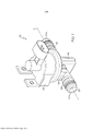
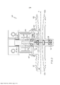
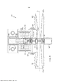
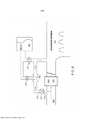
[009] As figuras 1 a 3 ilustram uma forma de realização de uma válvula de gaveta 100 adaptada para controlar de forma seletiva o fluxo de um fluido, por exemplo, o ar que flui a partir de uma entrada para um sistema de boost de freio a vácuo. A válvula de gaveta 100 pode apresenta um alojamento 102 que contém uma bobina do solenoide 104 e uma armadura 106 passível de ser conectada a um mecanismo da válvula 120. A armadura 106 inclui uma extremidade de inserção 106a recebida no interior da bobina do solenoide 104 e uma porção do corpo adjacente 107 que é mais completamente recebida no interior da bobina mediante a aplicação de uma corrente elétrica na bobina. Em uma construção, a extremidade de inserção 106a e a porção do corpo 107 podem ser cilindros fabricados a partir de um material magnético ou paramagnético, por exemplo, uma liga contendo ferro ou um material compósito contendo ferrite. Em outra construção, a extremidade de inserção 106a e a porção do corpo 107 podem ser cilindros apresentando um recesso interno 108 que afunila a partir da extremidade de inserção 106a na direção da porção do corpo 107 a fim de prover um aumento gradual na força de trazer para dentro. A conicidade pode ser configurada de modo que a força de trazer para dentro seja maior do que uma força de impulsão direcionada em oposição, produzida por um elemento de impulsão 110. Conforme mostrado na figura 2, o elemento de impulsão 110 pode ser uma mola helicoidal 112 em torno da porção do corpo 107 da armadura 106 e empurra tanto a bobina do solenoide 104 quanto uma extremidade sem inserção 106b, mas será apreciado que o elemento de impulsão poderia ser um diafragma ou mola plana projetante ou acoplada à extremidade sem inserção, uma mola de folha projetante ou acoplada à extremidade sem inserção, etc. Os especialistas na arte também apreciarão que o solenoide pode, em vez disso, ser um solenoide biestável incluindo outros elementos de impulsão.[009] Figures 1 to 3 illustrate an embodiment of a
[0010] O mecanismo da válvula 120 pode incluir um duto 122 que apresenta uma abertura de conexão 124, um bolso disposto opostamente 126, e um conjunto de gaveta para contra golpe 128 móvel de forma linear entre a abertura de conexão e o bolso. O duto 122 pode ser um tubo que se afunila ou estreita continuamente e gradualmente ao longo de um eixo longitudinal "A" a partir de ambas as extremidades na direção da abertura de conexão 124, apresentando, assim, o seu diâmetro interno menor na abertura de conexão 124 e disposto opostamente ao bolso 126. A seção transversal em forma de ampulheta 125 do trajeto do duto reduz as forças de atrito que atuam sobre as superfícies do conjunto de gaveta para contra golpe 128 durante o movimento através do duto 122. Esta seção transversal 125 também minimiza a queda de pressão através da válvula de gaveta 100. Em outras construções, o duto 122 pode apresentar um diâmetro interno uniforme ao longo de todo o seu comprimento. Nas construções ilustradas, a seção transversal perpendicular ao eixo longitudinal "A" é circular, mas, em variações, a seção transversal 127 pode ser elíptica (com diâmetros conjugados e transversais uniformes ou afunilados), poligonal (com larguras características uniformes ou afuniladas), etc.[0010] The
[0011] Na forma de realização das figuras 1 a 3, o conjunto de gaveta para contra golpe 128 é mecanicamente acoplado à armadura 106 por meio de uma haste 114 que se projeta a partir do interior do recesso interno 108. Em formas de realização alternativas, uma haste 114 pode se projetar a partir da extremidade inserida 106a da armadura 106 ou a partir da extremidade não inserida da armadura 106, dependendo de se a bobina do solenoide 104 e armadura 106 são configuradas para puxar a haste na direção, ou afastado, do mecanismo da válvula 120 e da abertura de conexão 124. Conforme mostrado na forma de realização das figuras 4 e 5, a disposição relativa da bobina do solenoide 104, da armadura 106, do elemento de impulsão 110 e da haste 114 pode ser alterada para mudar a válvula de gaveta 100 a partir de uma válvula normalmente fechada para uma válvula normalmente aberta ou vice-versa (dependendo da construção detalhada do conjunto de gaveta para contra golpe 128, conforme será descrito mais abaixo). Em algumas construções, a haste 114 pode ser uma projeção integral da armadura 106, mas em outras construções a haste pode ser projeção afixada, fabricada a partir de outro material, de preferência, não magnético.[0011] In the embodiment of figures 1 to 3, the
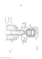
[0012] Uma extremidade da abertura de conexão da haste, 114a, pode ser afixada no conjunto de gaveta para contra golpe 128, mas o acoplamento mecânico é, de preferência, deslizável em relação ao conjunto de gaveta para contra golpe em ao menos uma direção paralela ao eixo longitudinal do duto. Em algumas construções, o acoplamento mecânico inclui um sistema de trilhas de guia 160 que permite o relativo movimento de deslizamento entre a haste 114 e o conjunto de gaveta para contra golpe 128 em uma direção paralela ao eixo longitudinal A. Este acoplamento mecânico deslizável permite que a armadura 106 mova de forma linear o conjunto de gaveta para contra golpe 128 entre a abertura de conexão 124 e o bolso 126 sem puxar o conjunto de gaveta na direção de qualquer extremidade do duto 122. No caso de um alinhamento não perfeito da bobina de solenoide 104, da armadura 106, e/ou da haste 114 com o mecanismo da válvula 120, de outro modo, empurrará o conjunto de gaveta para contra golpe 128 a partir de seu trajeto e, assim, tendendo a aumentar as forças de atrito entre o conjunto de gaveta e as paredes do duto 122. Na forma de realização mostrada nas figuras 2 e 3, o sistema de trilhas de guia 160 inclui uma trilha de guia 162 posicionada próximo da extremidade de abertura de conexão da haste 114a, com os sulcos em calha 164 dispostos nos lados opostos do mesmo. A extremidade da abertura de conexão do conjunto de gaveta para contra golpe 128a inclui correspondentemente um deslizador 166 configurado para envolver o trilho de guia 162 e se projetar no interior do sulco em calha 164. Em uma construção variante, o sistema de trilhos 160 pode ser revertido, com um deslizador 166 posicionado próximo da extremidade de abertura de conexão da haste 114a e os elementos do conjunto de gaveta para contra golpe 128, cada um incluindo um trilho de guia 162 e os sulcos em calha 164. Na forma de realização mostrada nas figuras 4 e 5, a extremidade de abertura de conexão da haste 114a pode incluir, uma cabeça em forma de placa alargada 167. Conforme melhor mostrado nas figuras 12 a 14, os elementos do conjunto de gaveta para contra golpe 128 podem alternativamente definir coletivamente um soquete de múltiplas partes 168 que se encaixa em torno da cabeça 167 para permitir o movimento de deslizamento em múltiplas direções perpendiculares à trajetória do movimento linear do conjunto de gaveta 128 deslizante.[0012] One end of the rod connection opening, 114a, may be affixed to the
[0013] Finalmente, o mecanismo da válvula 120 pode incluir uma porta de respiro 170 em comunicação fluída com a abertura de conexão 124 e, conforme melhor descrito abaixo, o conjunto de gaveta para contra golpe 128 e o bolso 126, para aliviar os fluidos que vazam fora do conjunto de gaveta para contra golpe e para o bolso. Em ambientes de fluxo altamente dinâmicos, por exemplo, um motor de automóvel em que a sobre alimentação é usada para aumentar a pressão do ar no interior de um coletor de admissão, as pressões diferenciais através da válvula de gaveta 100 podem variar amplamente e até mesmo reverter transitoriamente. O ar em alta pressão que vaza no bolso 126 pode pressurizar o bolso e alterar o equilíbrio da força de operação do solenoide, força de impulsão, e as esperadas forças de atrito no interior da válvula de gaveta 100. Uma grande diferencial na pressurização do mecanismo do solenoide e do bolso 126 pode impedir o mecanismo de gaveta para contra golpe de ser deslocado linearmente completamente no interior do bolso, fazendo com que a válvula opere em um estado parcialmente aberto e fechado. A porta de respiro 170 pode abrir para o interior do duto 122 a fim de permitir que o fluido flua a partir do bolso 126 para uma extremidade de entrada do duto 122a (conforme mostrado nas figuras 2 e 3) caso o fluido seja para ser contido no interior do sistema, ou pode abrir para o exterior do mecanismo da válvula 120 (conforme mostrado nas figuras 4 e 5) caso o fluido possa ser liberado para o ambiente.[0013] Finally, the
[0014] Com referência agora à figura 6, a válvula de gaveta 100 pode ser utilizada para controlar o fluxo de ar através de um sistema de freio a vácuo. O duto pode ser conectado a uma entrada de ar 180 em uma extremidade de entrada 122a e a um gerador de vácuo, no exemplo ilustrado, um aspirador 190, em uma extremidade de saída 122b. Em uma configuração de exemplo de motor sobre-alimentado, um turbo-compressor e o trocador de calor do ar 182 podem pressurizar o ar a ser fornecido a um coletor de entrada 184, fazendo com que a pressão no interior do coletor de admissão supere a pressão de ar na extremidade de entrada 122a e, potencialmente, provocando um fluxo reverso transitório através do aspirador 190. As válvulas de gaveta 192 evitam que o sistema de freio 194 perca a sua carga de vácuo, no entanto, o fluxo reverso através do aspirador 190 pode fazer com que a pressão do fluido na extremidade de saída 122b exceda a da extremidade de entrada 122a. Este diferencial de pressão revertida pode ser ainda maior do que o diferencial de pressão comum através da válvula de gaveta 100, uma vez que os turbo- compressores costumeiramente fornecem pressões de boost de cerca de 1 atmosfera (relativa) e, em tais elevadas pressões de boost, a pressão na extremidade de entrada 122a possivelmente é substancialmente menor do que 1 atmosfera (absoluta). Consequentemente, diferentes formas de realização de um conjunto de gaveta para contra golpe 128, melhor descrito a seguir, podem ser mais adequadas para algumas aplicações. Em adição, os especialistas irão apreciar que a válvula de gaveta 100 pode ser usada em outras aplicações, incluindo aplicações não automotivas, e com outros fluidos que além do ar.[0014] Referring now to Figure 6, the
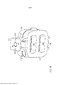
[0015] Com referência às figuras 7 a 9, é ilustrada outra forma de realização de um conjunto de gaveta para contra golpe, designado genericamente com o número de referência 228. O conjunto de gaveta para contra golpe 228 inclui um primeiro elemento de gaveta 230, um segundo elemento de gaveta 232, e uma banda elástica contínua 234 recebida entre os primeiros e segundos elementos de gaveta 230, 232. A banda elástica contínua 234 pode ser descrita como sendo envolta entre os primeiro e segundo elementos de gaveta 230, 232. Conforme se vê na figura 9, o segundo elemento de gaveta 232 inclui uma trilha de guia 236, para receber uma porção da banda elástica contínua, em torno de uma porção da sua superfície interior 252. Apesar de não ser visível nas figuras 7 a 9, o primeiro elemento de gaveta 230 também inclui uma trilha de guia 236.[0015] Referring to Figures 7 to 9, another embodiment of a backstop drawer assembly, designated generically with
[0016] Os primeiro e segundo elementos de gaveta 230, 232 podem ser os mesmos ou elementos substancialmente semelhantes, mas não são intrinsecamente limitados a essa condição. Tal como ilustrado nas figuras 7 e 9, em que os primeiro e segundo elementos de gaveta 230, 232 são os mesmos, cada um deles pode ser posicionado de frente tanto para a extremidade de entrada 122a quanto para a extremidade de saída 122b do duto 122. Isto produz uma válvula com desempenho semelhante, independentemente da direção do fluxo no duto 122.[0016] The first and
[0017] Com referência às figuras 7 e 9, especificamente, tanto o primeiro elemento de gaveta 230 quanto o segundo elemento de gaveta 232 apresentam as aberturas 233 que definem coletivamente uma passagem 229. Em uma posição aberta, tal como ilustrado na figura 5, a passagem 229 através do conjunto de gaveta para contra golpe 228 é alinhada com o duto 122 para permitir que o fluido flua através da mesma. A porção da gaveta que apresenta a passagem 229 é aqui referida como a porção de aberta posição 240 (figura 7), e a porção adjacente, ilustrada oposta à extremidade de abertura de conexão 228a que apresenta um deslizador 266, é referida como a porção de posição fechada 242 devido a esta porção da gaveta 228, quando movida para uma posição fechada, obstrui o duto 122 para impedir o fluxo de fluido através do mesmo. A porção de posição fechada 242 de cada elemento de gaveta 230, 232, nesta forma de realização, apresenta uma superfície externa substancialmente lisa e contínua 250. Os especialistas apreciarão que as porções de posição aberta e de posição fechada 240, 242 podem ser invertidas, com a porção de posição aberta 240 oposta à extremidade de abertura de conexão 228a, fornecendo um segundo meio de mudança de uma concepção da válvula de gaveta normalmente fechada para normalmente aberta (ou vice-versa).[0017] With reference to Figures 7 and 9 specifically, both the
[0018] Nesta forma de realização ilustrada, a banda elástica contínua 234 é genericamente de conformação oval e, assim, inclui um perímetro interno 282 que define um espaço aberto, um perímetro externo 284, e em oposição aos primeiro e segundo lados 286, 288. A banda elástica contínua 234 é recebida nas trilhas de guia 236 dos primeiro e segundo elementos de gaveta 230, 232 com o primeiro lado 286 recebido em uma trilha de guia 236 e o segundo lado 288 recebido na outra trilha de guia 236. Quando a banda contínua 234 é assentada nas trilhas de guia 236 dos primeiro e segundo elementos de gaveta 230, 232, os primeiro e segundo elementos de gaveta 230, 232 são afastados um do outro por uma distância D (figura 7). As trilhas de guia 236 são posicionadas para rebaixar a banda elástica contínua 234 a uma distância a partir do perímetro externo dos elementos de gaveta. Conforme pode ser visto na figura 8, esta construção define um canal 254 em torno da superfície externa da banda elástica contínua 234 entre os primeiro e segundo elementos de gaveta 230, 232 para o fluxo em torno da gaveta para contra golpe 228 no interior do bolso 126 e a comunicação fluída com a porta de respiro 170. Este respiro através do canal 254 é em geral perpendicular à direção do fluxo através do duto 122 e o fluido alivia a partir do bolso 126 através da abertura do conector 124 (passa e/ou atravessa o acoplamento mecânico) conforme a armadura 106 movimenta a gaveta mais completamente para dentro do bolso.[0018] In this illustrated embodiment, the continuous
[0019] A banda elástica contínua 234 é compressível entre os primeiro e segundo elementos de gaveta 230, 232 e, portanto, funciona como uma mola que atua paralelamente à direção do fluxo através do duto 122. Em adição, a banda elástica contínua 234 é radialmente expansível para fora, em resposta às forças aplicadas na banda elástica contínua 234 pelo fluido que flui através do duto 122 para formar uma vedação entre a banda elástica contínua 234 e a porção da parede externa das trilhas de guia 236 nos primeiro e segundo elementos de gaveta 230, 232.[0019] The continuous
[0020] Em operação, na posição aberta tal como ilustrado nas figuras 2 e 5, o fluido que flui através do duto, se fluir da esquerda para a direita ou da direita para a esquerda, passa através da passagem 229 no conjunto de gaveta para contra golpe 228 e a pressão do fluido fornece uma força que atua sobre a banda elástica contínua 234 direcionada radialmente para fora, pressionando desse modo a banda elástica contínua em um engate estanque com o perímetro externo das trilhas de guia 236. Este engate estanque reduz ou previne o vazamento de fluido para dentro da abertura do conector 124 e do bolso 126, o que torna o conjunto de gaveta para contra golpe 228 mais resistente a vazamentos do que uma gaveta de apenas um material, uniformemente rígida. Esta forma de realização é bastante adequada para uso com motores naturalmente aspirados, em particular, com o ar que flui às pressões atmosféricas ou sub-atmosféricas, através do duto 122. No entanto, em uma forma de realização em que o duto 122 é conectado no lado da pressão de boost de um sistema de admissão de ar super-alimentado, a proteção ao vazamento fornecida pela banda elástica contínua 234 auxilia na prevenção de que o fluido que flui através do duto 122 gere pressões no interior do bolso 126, que poderiam atuar empurrando o conjunto de gaveta para contra golpe 228 (e armadura 106, etc.) para outra posição ou, de outra forma, impeça o movimento controlado do conjunto. As pressões em um motor super-alimentado, e experimentadas pelo conjunto de gaveta para contra golpe 228 e válvula de gaveta 100, geralmente, variam entre cerca de 5 psi a cerca de 30 psi.[0020] In operation, in the open position as illustrated in Figures 2 and 5, fluid flowing through the duct, whether flowing from left to right or right to left, passes through
[0021] A banda elástica contínua 234 também produz uma gaveta que é menos sensível às tolerâncias de fabricação, em particular, no que se refere às dimensões do bolso 126 e a espessura dos elementos de gaveta 230, 232, devido à presença da banda elástica contínua. O bolso 126 é tipicamente formado para apresentar uma largura que é menor do que a largura de uma gaveta descarregada, de modo a produzir um encaixe com interferência. No conjunto de gaveta para contra golpe 228, a banda elástica contínua 234 torna-se comprimida entre os primeiro e segundo elementos de gaveta 230, 232 conforme a gaveta para contra golpe 228 é inserida no bolso 126. A força de mola da banda elástica contínua sobre os primeiro e segundo elementos de gaveta 230, 232, quando inseridos ou encaixados no bolso 126 pressiona cada respectivo elemento de gaveta em um engate estanque com a parede do bolso para reduzir ou prevenir vazamentos. Ainda mais importante, o módulo de elasticidade substancialmente menor da banda elástica contínua versus o dos elementos rígidos de gaveta 230, 232, ou o de uma única gaveta rígida, significa que as forças normais que atuam sobre o conjunto de gaveta para contra golpe 228 e resistem ao movimento linear do conjunto ao longo de sua trajetória são substancialmente menores. Isso reduz as forças de atrito (força de atrito é igual à força normal vezes o coeficiente de atrito) e, assim, a força de operação do solenoide requerida. Este benefício é igualmente aplicável às outras formas de realização descritas abaixo.[0021] The continuous
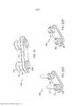
[0022] Com referência agora às figuras 10 e 11, é fornecida outra forma de realização de um conjunto de gaveta para contra golpe, designado genericamente com o número de referência 228', o qual de modo semelhante inclui um primeiro elemento de gaveta 230', um segundo elemento de gaveta 232', e uma banda elástica contínua 235' recebida entre os primeiro e segundo elementos de gaveta 230', 232'. A banda elástica contínua 235' pode ser descrita como sendo envolta entre os primeiro e segundo elementos de gaveta 230', 232'. Como pode ser visto na figura 11, o segundo elemento de gaveta 232' inclui uma trilha de guia 237' em torno de uma porção de sua superfície interna 252' para receber uma porção da banda elástica contínua 235'. Apesar de não ser visível nas figuras 10 e 11, o primeiro elemento de gaveta 230' também inclui uma trilha de guia 237'. Ambos os elementos de gaveta 230', 232' apresentam uma extremidade de abertura de conexão 228a que apresenta um deslizador 266' para acoplar de forma deslizante o conjunto de gaveta 228' na armadura 106 conforme descrito acima. No entanto, conforme descrito acima, em todas as formas de realização, os elementos 230, 230' 232, 232', etc., podem alternativa mente incluir uma trilha guia e sulco em calha semelhante à trilha de guia 162 e sulco em calha 164 da haste 114.[0022] Referring now to Figures 10 and 11, there is provided another embodiment of a backlash drawer assembly, designated generically with reference numeral 228', which similarly includes a first drawer element 230' , a second drawer member 232', and a continuous elastic band 235' received between the first and second drawer members 230', 232'. The continuous elastic band 235' can be described as being wrapped between the first and second drawer elements 230', 232'. As can be seen in Figure 11, the second drawer element 232' includes a guide track 237' around a portion of its inner surface 252' to receive a portion of the continuous elastic band 235'. Although not visible in Figures 10 and 11, the first drawer element 230' also includes a guide track 237'. Both drawer elements 230', 232' have a connecting
[0023] Conforme ilustrado na figura 11, a banda elástica contínua 235' é, genericamente, uma banda conformada em oito de material elástico e, portanto, inclui um primeiro perímetro interno 272 que define um primeiro espaço aberto, um segundo perímetro interno 273 que define um segundo espaço aberto, um perímetro externo 274, e em oposição aos primeiro e segundo lados 276, 278. A banda elástica contínua 235' é recebida nas trilhas de guia 237' dos primeiro e segundo elementos de gaveta 230', 232' com o primeiro lado 276 recebido em uma trilha de guia 237' e o segundo lado 278 recebido na outra trilha de guia 237'. Uma vez que a banda elástica contínua 235' é conformada em oito, a trilha de guia 237' também é tipicamente conformada em oito. Quando a banda elástica contínua 235' é assentada nas trilhas de guia 237' dos primeiro e segundo elementos de gaveta 230', 232', os primeiro e segundo elementos de gaveta 230', 232' são afastados um do outro por uma distância D' (figura 10). As trilhas de guia 237' são posicionadas para rebaixar a banda elástica contínua 235' a uma distância a partir do perímetro externo dos primeiro e segundo elementos de gaveta 230', 232' para prover o alívio conforme descrito acima em relação às figuras 7 a 9.[0023] As illustrated in Figure 11, the continuous elastic band 235' is generally an eight-shaped band of elastic material and therefore includes a first
[0024] Os primeiro e segundo elementos de gaveta 230', 232' são estruturalmente diferentes um do outro, mas ambos apresentam as primeiras aberturas 233' que definem coletivamente uma passagem 229' que, em uma posição aberta, é alinhada com o duto 122 para permitir que o fluido flua através dele. Esta porção da gaveta é referida como a porção de posição aberta 240' (figura 10), e uma porção adjacente à mesma, oposta ao deslizador 266', é referida como a porção de posição fechada 242" devido a esta porção do conjunto de gaveta para contra golpe 228', quando movida para uma posição fechada, obstrui o duto 122 através para prevenir o fluxo através do mesmo. Nesta forma de realização, a porção de posição fechada 242' do primeiro elemento de gaveta 230' inclui uma segunda abertura 244' através dele. A segunda abertura pode ser dimensionada substancialmente do mesmo modo que a primeira abertura 233'. O segundo elemento de gaveta 232' não inclui uma segunda abertura na porção de posição fechada 242' do mesmo. Em vez disso, a porção fechada 242' do segundo elemento de gaveta 232' apresenta uma superfície externa substancialmente lisa e contínua. O segundo elemento de gaveta 232' pode, opcionalmente, incluir um plugue 253' que se projeta a partir de sua superfície interna 252', configurado para encaixar dentro das dimensões do segundo espaço aberto definido pela banda elástica contínua 235', e dimensionado de modo a ser ao menos do tamanho da segunda abertura 244' no primeiro elemento de gaveta 230', a qual define uma abertura menor do que o segundo perímetro interno 273 da banda elástica contínua 235'. O plugue 253' pode ser uma porção substancialmente lisa da superfície interna 252' do segundo elemento de gaveta 232'.[0024] The first and second drawer elements 230', 232' are structurally different from each other, but both have first openings 233' that collectively define a passage 229' which, in an open position, is aligned with the
[0025] Na posição aberta, o fluido que flui através da passagem 229' fornece uma força que atua sobre a banda elástica contínua 235', direcionada radialmente para fora, desse modo pressionando a banda elástica contínua em engate estanque com o perímetro externo das trilhas de guia 237'. Este contato de vedação reduz ou previne o vazamento de fluido para dentro da abertura do conector 124 e para dentro do bolso 126, o que torna a gaveta 228', na forma de realização das figuras 10 e 11, mais resistente ao vazamento do que uma gaveta feita de único material, uniformemente rígida.[0025] In the open position, fluid flowing through passage 229' provides a force acting on the continuous elastic band 235', directed radially outward, thereby pressing the continuous elastic band into tight engagement with the outer perimeter of the tracks guide 237'. This sealing contact reduces or prevents leakage of fluid into the
[0026] Na posição fechada, o fluxo no duto 122 pode ser na direção para o lado da gaveta para contra golpe 228', definida pelo primeiro elemento de gaveta 230', ou seja, o primeiro elemento de gaveta 230' pode ser de frente para uma extremidade de entrada 122a da válvula de gaveta 100. Em particular, esta orientação de fluxo é benéfica quando o duto 122 é conectado no lado de pressão de boost de um sistema de admissão de ar super-alimentado e, geralmente, é operado para parar o fluxo da pressão de boost através dele. Ou seja, devido à pressão passar através da segunda abertura 244' e ser direcionada pelo plugue 253' para o segundo perímetro interno 273 da banda elástica contínua 235', atua sobre a banda elástica contínua radialmente para fora para engatá-la de modo estanque contra as trilhas de guia 237' dos primeiro e segundo elementos de gaveta 230', 232'. A presença da segunda abertura 244' também minimiza a área de superfície da superfície externa do primeiro elemento de gaveta 230' sobre a qual a pressão de boost pode aplicar uma força que atua paralelamente à direção do fluxo no interior do duto 122 para comprimir axialmente a banda elástica infinita 235'. Se a pressão de boost comprimir a banda elástica contínua 235' na direção axial, um dentre os elementos de gaveta 230', 232' deverá se aproximar do outro, diminuindo a distância D', e criando um vão entre uma parede do bolso 126 e tal elemento de gaveta através do qual o fluido pode vazar. Este é um resultado indesejável. Portanto, para elemento de gaveta 228', seria indesejável que a pressão de boost flua para o interior do duto em uma direção que iria impactar a superfície externa substancialmente lisa e contínua do segundo elemento de gaveta 232'. No exemplo ilustrado na figura 6, a orientação oposta de fluxo é benéfica uma vez que o diferencial de pressão mais elevado provavelmente é um diferencial de pressão inverso causado pela pressão de boost no interior do coletor de admissão que atravessa o aspirador em um lado de saída da válvula de gaveta.[0026] In the closed position, the flow in the
[0027] Com referência agora às figuras 12 a 14, em uma variante desta ou de outras formas de realização, um dentre os elementos de gaveta 230', 232' pode incluir uma trava 281 e o outro dentre os elementos de gaveta 230', 232' pode incluir um retentor 283 correspondentemente disposto. Conforme ilustrado, um pode incluir uma pluralidade de travas 281 e o outro pode incluir uma pluralidade de retentores 283, ou cada um deles pode incluir uma trava 281 e um retentor 283, com a trava 281 e o retentor 283 dispostos nas extremidades opostas dos elementos 230', 232' para corresponder à disposição de seu elemento complementar. As travas 281 e retentores 283 auxiliam na montagem do conjunto de gaveta para contra golpe 228' (ou 128, 228, etc.) por meio da retenção ativa do conjunto em uma configuração montada antes da inserção no interior do bolso 126. Em adição, em uma variante desta ou outras formas de realização, os elementos de gaveta 230', 232' podem definir coletivamente um soquete de múltiplas partes 268 que se encaixa em torno da cabeça 167 (não visível na figura 14) da haste 114 do acoplamento mecânico. O soquete 268 auxilia na montagem do conjunto de gaveta para contra golpe 228' (ou 128, 228, etc.) por meio da retenção ativa do conjunto sobre a haste 114 antes da inserção no interior do bolso 126.[0027] Referring now to figures 12 to 14, in a variant of this or other embodiments, one of the drawer elements 230', 232' may include a
[0028] Com referência agora às figuras 15 a 17, um conjunto universal de gaveta para contra golpe (operacional com o fluxo direcionado para qualquer um dentre o primeiro ou o segundo elementos de gaveta) é ilustrado e designado pelo número de referência 328. A gaveta universal para contra golpe 328 apresenta o mesma primeiro elemento de gaveta 230' tal como na forma de realização nas figuras 10 e 11, um segundo elemento de gaveta 332 que apresenta a mesma construção geral do primeiro elemento de gaveta 230', um elemento interno de gaveta 334 que fornece a obstrução necessária para a posição fechada, uma primeira banda elástica contínua 346 disposta no interior de uma trilha de guia definida entre o primeiro elemento de gaveta 230' e o elemento interno de gaveta 334, e uma segunda banda elástica contínua 348 disposta no interior de uma trilha de guia definida entre o segundo elemento de gaveta 332 e o elemento interno de gaveta 334. O segundo elemento de gaveta 332, ver a figura 13, pode incluir um deslizador 366, uma primeira abertura 333 na porção de posição aberta 240', e uma segunda abertura 344 na porção de posição fechada 242' da mesma. O elemento interno de gaveta 334 inclui uma abertura 336 em uma porção de posição aberta 240' da mesma e apresenta superfícies opostas externas substancialmente contínuas que definem a porção de posição fechada 242', que pode obstruir o fluxo através do duto quando a gaveta universal para contra golpe 328 estiver na posição fechada.[0028] Referring now to Figures 15 to 17, a universal backlash drawer assembly (operational with flow directed to either the first or second drawer elements) is illustrated and designated by
[0029] Na forma de realização das figuras 15 a 17, uma banda elástica contínua conformada em oito é preferida devido às duas aberturas em cada um dentre os primeiro e segundo elementos de gaveta 230', 332. As bandas elásticas contínuas 346, 348 conformadas em oito são conforme descrito acima. Aqui, a primeira banda elástica contínua 346 é assentada tanto em uma primeira pista 352 no elemento interno de gaveta 334 quanto em uma trilha de guia 237' no primeiro elemento de gaveta 230', que são, de preferência, conformadas em oito, dimensionadas para receber a primeira banda elástica contínua 346. Da mesma forma, a segunda banda elástica contínua 348 é assentada tanto uma segunda trilha de guia 354 no elemento interno de gaveta 334 quanto em uma trilha de guia 337 no segundo elemento de gaveta 332, que são, de preferência, conformadas em oito, dimensionadas para receber a segunda banda elástica contínua 348.[0029] In the embodiment of Figures 15 to 17, an eight-shaped continuous elastic band is preferred because of the two openings in each of the first and
[0030] Em operação, a gaveta universal para contra golpe 328, na posição aberta e na posição fechada, opera conforme descrito acima em relação ao primeiro lado do elemento de gaveta da gaveta para contra golpe 228' das figuras 10 e 11. A gaveta universal para contra golpe 328 pode ser utilizada normalmente em motores aspirados, super- alimentados ou turbo, sem a necessidade de qualquer orientação particular de fluxo. A sua natureza universal e o benefício da área de superfície reduzida na porção de posição fechada de cada um dentre os primeiro e segundo elementos de gaveta torna esta gaveta funcional para selar a gaveta, a fim de reduzir ou prevenir o vazamento na abertura do conector 124 e bolso 126, independentemente da direção do fluxo através do duto. Esta forma de realização também apresenta o benefício de fornecer múltiplos canais 254 em torno do exterior da banda elástica contínua para fornecer a comunicação fluída entre o bolso e a porta de respiro 170.[0030] In operation, the
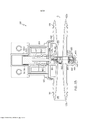
[0031] Com referência às figuras 18 a 23, é ilustrada outra forma de realização de um conjunto de gaveta para contra golpe, designado genericamente com o número de referência 428. O conjunto de gaveta para contra golpe 428 inclui um primeiro elemento de gaveta 430, um segundo elemento de gaveta 432, e uma banda elástica contínua 434, recebida ou envolta entre os primeiro e segundo elementos de gaveta 430, 432. Conforme se vê nas figuras 18 e 19, cada um dentre os primeiro e segundo elementos de gaveta 430, 432 inclui uma trilha de guia 436 para receber uma porção da banda elástica contínua 434 em torno de uma porção de suas respectivas superfícies internas 452. Cada um dentre os primeiro e segundo elementos de gaveta 430, 432 também apresenta as aberturas 433 através de uma porção de posição aberta 440 para definirem coletivamente uma passagem 429 de modo que, quando a válvula de gaveta estiver aberta, a passagem será alinhada com um duto para permitir que o fluido flua através do mesmo. Similarmente, cada um dentre os primeiro e segundo elementos de gaveta 430, 432 apresenta uma porção de posição fechada 442, mas, em contraste com os elementos de gaveta 230 e 232, apenas o primeiro elemento de gaveta 430 pode incluir uma superfície externa contínua lisa 450 (sugerida, mas não especifica mente mostrada) ao longo de sua porção de posição fechada 442. O segundo elemento de gaveta 432 pode, em vez disso, apresentar um recesso voltado para o exterior 451 que inclui uma abertura da válvula de gaveta 456, que é selado de forma seletiva por um elemento da válvula de gaveta 490, e uma pluralidade de aberturas de retenção da válvula de gaveta 458, que recebem e retém uma pluralidade de retentores da válvula de gaveta 494. A abertura da válvula de gaveta 456 e as aberturas do retentor da válvula de gaveta 458 são mostradas como uma linha de aberturas circulares substancialmente idênticas, mas deverá ser entendido que diferentes configurações de abertura, formatos de abertura, e quantidades de aberturas circulares [bead\ da válvula de gaveta podem ser usadas desde que ao menos um par de aberturas de retenção da válvula de gaveta 458 suporte a abertura da válvula de gaveta 456. A superfície interna 452 da porção de posição fechada 442 do primeiro elemento de gaveta 430 pode, opcionalmente, incluir uma pluralidade de colunas batentes internamente projetantes 459 configuradas para se alinhar com a abertura de retenção da válvula de gaveta 458 durante a montagem dos primeiro e segundo elementos de gaveta 430, 432. Conforme será explicado abaixo, as extremidades internas das colunas batentes 459 podem funcionar para evitar o desengate dos retentores da válvula de gaveta 494 das aberturas de retenção da válvula de gaveta 458 do segundo elemento de gaveta 432 durante os momentos iniciais dos eventos de alta pressão.[0031] Referring to Figures 18 to 23, another embodiment of a backstop drawer assembly, designated generically with
[0032] Conforme mostrado, as extremidades de conexão 428a dos primeiro e segundo elementos de gaveta 430, 432 podem definir um soquete de múltiplas partes 468 que se encaixa em torno de uma cabeça 167 da haste da armadura 114 para permitir o movimento deslizante em múltiplas direções perpendiculares ao trajeto de movimento linear do conjunto de gaveta deslizante 428. Em alternativa, conforme descrito em outras formas de realização, as extremidades de conexão 428a dos primeiro e segundo elementos de gaveta 430, 432 podem ser afixadas à haste da armadura 114, ou podem ser deslizáveis em relação à haste da armadura 114 em uma direção paralela ao eixo longitudinal do duto. Tal como no sistema de trilhos 160, cada extremidade de abertura de conexão 428a pode incluir uma trilha de guia com sulcos em calha dispostos em lados opostos da mesma ou um deslizador configurado para envolver em torno da trilha de guia e se projetar para o interior dos sulcos em calha, dependendo da disposição relativa das trilhas de guia/sulcos em calha e dos elementos deslizantes sobre a extremidade de abertura de conexão 114a da haste 114 e a extremidade de abertura de conexão 428a do conjunto de gaveta para contra golpe 428.[0032] As shown, the connecting ends 428a of the first and
[0033] Voltando à figura 20, a banda elástica contínua 434 inclui um perímetro interno 482 que define um espaço aberto, um perímetro externo 484, e os primeiro e segundo lados opostos 486, 488. A banda elástica contínua 434 é recebida nas trilhas de guia 436 com o primeiro lado 486 recebido em uma trilha de guia 436 e o segundo lado 488 recebido na outra trilha de guia 436 de tal modo que o primeiro elemento de gaveta 430, o segundo elemento de gaveta 432 e a banda elástica contínua 434 definem em conjunto uma câmara 438. Para reduzir a constante da mola da banda elástica contínua 434, o(s) perímetro(s) da banda pode apresentar uma seção transversal longitudinal das paredes sanfonadas que permite que a banda comprima mais facilmente entre os elementos de gaveta 430 e 432 sem se envolver a um material de menor módulo. Os primeiro e segundo elementos de gaveta 430 e 432 podem, opcionalmente, serem atrelados um ao outro por meio das travas 481 e os retentores 483 correspondentemente dispostos, tal como descrito em outras formas de realização acima, ou podem ser atrelados um ao outro por meio da fixação do primeiro lado 486 da banda 434 na trilha de guia 436 e fixando o segundo lado 488 da banda 434 na outra trilha de guia 436. A fixação pode ser realizada por meio da adesão dos lados 486, 488 no interior das respectivas trilhas de guia 436 ou um encaixe com interferência entre os lados 486, 488 e as respectivas trilhas de guia 436. Como pode ser visto na figura 23, esta construção define um canal 454 em torno da superfície externa da banda elástica contínua 434 entre os primeiro e segundo elementos de gaveta 430, 432 para o fluxo de fluido em torno da gaveta para contra golpe 428 no interior do bolso 126 e a porta de respiro 170. Como nas construções anteriores, o respiro através do canal 454 alivia o fluido do bolso 126 através da abertura do conector 124 (passa e/ou atravessa o acoplamento mecânico) conforme a armadura 106 movimenta a gaveta 428 mais completamente para dentro do bolso. Em adição, esta construção define coletivamente uma câmara 438 que se estende entre a porção de posição aberta 440 e a porção de posição fechada 442 de ambos os elementos de gaveta 430, 432.[0033] Returning to Figure 20, the continuous
[0034] A banda elástica contínua 434 é compressível entre o primeiro e o segundo elementos de gaveta 430, 432 e, portanto, funciona como uma mola que atua paralelamente à direção do fluxo através do duto 122. Em adição, a banda elástica contínua 434 é expansível radialmente para fora em resposta às forças aplicadas à banda pela passagem de fluido para dentro da câmara 438 através das aberturas 433. Finalmente, quando a válvula de gaveta se encontra na posição fechada, a banda elástica contínua 434 é expansível entre o primeiro e segundo elemento de gaveta 430, 432, em resposta à pressurização da câmara 438. A pressurização é controlada pelo elemento da válvula de gaveta 490, que permite uma comunicação fluida seletiva com a câmara 438 para permitir o fluxo a partir do duto 122 para dentro da câmara 438, mas não a partir da câmara 438 para o duto 122. Conforme mostrado na figura 23, o segundo elemento de gaveta 432 pode ser orientado para a extremidade de saída 122b do duto, de modo que, os diferenciais de pressão transitoriamente revertidos nas configurações de motor super- alimentado, provocados pelas pressões de boost dentro do coletor de admissão, podem pressurizar a câmara 438. Conforme observado anteriormente, o diferencial de pressão revertido pode ser ainda maior do que o diferencial de pressão normal e, assim, pode comprimir a banda elástica contínua 434 para uma extensão maior do que a normal, e pode fazer com que o segundo elemento de gaveta 432 se aproxime do primeiro 430, criando um vão com uma parede do bolso 126 através do qual o fluido pode vazar. A pressurização da câmara 438 irá reduzir o diferencial de pressão entre a câmara 438 e a extremidade de saída 122b do duto 122, assim como a tendência do diferencial de pressão comprimir a banda elástica contínua 434 na direção axial. Isso impede que o segundo elemento de gaveta 432 seja mantido afastado da parede adjacente do bolso 126, e, portanto, reduz a necessidade de conceber a taxa elástica da banda elástica contínua 434 de modo a resistir à sobre-compressão pelos diferenciais de pressão de boost, em vez da compressão mais pelos diferenciais de pressão atmosféricas normais.[0034] The continuous
[0035] Conforme mostrado nas figuras 21, 22A, e 22B, o elemento da válvula para contra golpe 490 pode compreender um material elastomérico que apresenta uma superfície de vedação geralmente plana 492 e uma pluralidade de retentores projetantes da válvula de gaveta 494 que suportam a superfície de vedação. Cada um dentre os retentores da válvula de gaveta 494 pode compreender uma porção de pescoço 495 adaptada para se estender através de, e plugar, uma abertura do retentor da válvula de gaveta 458 e uma porção da cabeça 496, adaptada para ser puxada, mas que de outra forma, retida com interferência pelas paredes da abertura do retentor da válvula de gaveta 458. Conforme mostrado na figura 21A, o processo durante a montagem da porção da cabeça 496, pode incluir uma extensão de aba sacrificial 497, que é inserida através de uma abertura do retentor da válvula de gaveta 458 e, em seguida, puxada para trazer a porção da cabeça 496 através da abertura, após o que a extensão da aba 497 pode ser removida para evitar a interferência com a operação do conjunto de gaveta para contra golpe 428. O elemento da válvula de gaveta 490 também pode compreender uma pluralidade de batentes do retentor opostamente projetantes 498 alinhados com os retentores projetantes da válvula de gaveta 494. As extremidades internas das colunas de batente 459 do primeiro elemento de gaveta 430 podem, após a montagem do conjunto de gaveta 428, ser dispostas na proximidade do lado interno do elemento da válvula de gaveta 490 e, se incluso, os batentes do retentor opostamente projetantes 498, a fim de assegurar que os retentores da válvula de gaveta 494 não sejam expulsos das aberturas do retentor da válvula de gaveta 458 durante os repentinos e grandes diferenciais de pressão reversa no interior do duto 122. O deslocamento da superfície de vedação geralmente plana 492 a partir da abertura da válvula de gaveta 456 do segundo elemento de gaveta 432 permite que a câmara 438 pressurize durante tais eventos, revertendo qualquer sobre-compressão da banda elástica contínua 434.[0035] As shown in Figures 21, 22A, and 22B, the
[0036] Conforme mostrado na figura 23, o conjunto de gaveta para contra golpe 428 pode ser instalado no interior do mecanismo da válvula 120 com o segundo elemento de gaveta 432 orientado para a extremidade de saída 122b do duto 122. Quando o conjunto de gaveta para contra golpe 428 se encontra na posição aberta, as aberturas 433 através das porções de posição aberta 440 e da passagem 429 são alinhadas com o duto 122 para permitir que o fluido flua através do mesmo. Quando o conjunto de gaveta para contra golpe 428 é movido para a posição fechada, as aberturas 433 através das porções de posição aberta 440 e da passagem 429 são removidas do alinhamento com o duto 122 (tal como ilustrado dentro do bolso 126, mas, tal como descrito acima, potencialmente para dentro da abertura de conexão 124, caso as porções de posição aberta 440 e as porções de posição fechada 442 sejam invertidas), e a banda elástica contínua 434 impulsiona os primeiro e segundo elementos de gaveta 430, 432 para um engate estanque com as paredes da abertura de conexão 124 e do bolso 126. Em conformidade, a superfície externa contínua lisa 450 do primeiro elemento de gaveta 430 bloqueia o fluxo a partir da extremidade de entrada 122a para a extremidade de saída 122b do duto 122. O elemento da válvula de gaveta 490 também fornece uma vedação adicional, impedindo o vazamento em torno do primeiro elemento de gaveta 430 ou através da abertura de conexão 124 a partir de ter sido comunicado com a extremidade de saída 122b do duto 122. Se ocorrer um evento de diferencial de pressão revertido, o elemento da válvula de gaveta 490 do segundo elemento de gaveta 432 permite que a câmara 438 pressurize, e a superfície externa lisa contínua 450 do primeiro elemento de gaveta 430 bloqueia o fluxo a partir da extremidade de saída 122b para a extremidade de entrada 122a do duto 122. Em adição, a pressurização da câmara 438 reduz o diferencial de pressão revertida entre a extremidade de saída 122b e a câmara 438 (ou seja, o diferencial de pressão através do segundo elemento de gaveta 432), permitindo que a banda elástica contínua 434 retorne ou continue a pressionar o segundo elemento de gaveta 432 no engate estanque com a parede adjacente do bolso 126. Quando o conjunto de gaveta para contra golpe 428 é retornado para a posição aberta, a câmara 438 não pode se comunicar de modo seletivo com o duto 122 através das aberturas 433, permitindo que a câmara despressurize.[0036] As shown in Figure 23, the
[0037] Em contraste com a forma de realização mostrada nas figuras 7 a 9, o conjunto de gaveta para contra golpe 428 não exige que a banda elástica contínua 234/434 apresente uma constante elástica capaz de resistir a um diferencial de pressão reversa provocada pela pressão de boost no interior do coletor de admissão (ou outros eventos análogos). Isto reduz as forças normais que atuam sobre o conjunto de gaveta para contra golpe 428 e, assim, as forças de atrito que resistem ao movimento linear do conjunto ao longo de seu trajeto, bem como a força de operação necessária do solenoide. Em contraste com as formas de realização mostradas nas figuras 2 a 5 e 10 a 17, o conjunto gaveta para contra golpe 428 não usa uma banda conformada em oito 235' para fornecer uma vedação adicional entre porção de posição aberta 2407440 (incluindo as aberturas 2337433) e a porção de posição fechada 2427442 (e segunda abertura 244' ou as aberturas 244' e 344). Isto pode reduzir a complexidade dos moldes para a banda elástica contínua 434 e dos primeiro e segundo elementos de gaveta 430, 432, mas, mais vantajosa mente, pode reduzir o trajeto necessário do atuador para movimentar o conjunto de gaveta para contra golpe 428 a partir de uma posição aberta para uma posição fechada, e vice versa. Como pode ser visto pela comparação das figuras 2 a 5 e com as figuras 18 e 19 e 23, a distância a partir da extremidade de abertura de conexão 128a/428a do respectivo conjunto de gaveta para contra golpe 128, 428 à da extremidade oposta daquela do conjunto pode ser reduzida por meio essencialmente da eliminação dos segmentos centrais da trilha de guia 237' e banda 235' (detalhado na figura 11) que separa as porções de posição aberta e fechada do conjunto.[0037] In contrast to the embodiment shown in figures 7 to 9, the
[0038] Em um aspecto, é descrita aqui uma válvula atuada por solenoide. O solenoide aciona um conjunto de gaveta para contra golpe que compreende uma banda elástica contínua retida entre um primeiro elemento de gaveta e um segundo elemento de gaveta que definem coletivamente uma passagem através do conjunto de gaveta em uma posição aberta, em que a passagem através da gaveta é alinhada com um duto, e uma posição fechada em que uma segunda porção da gaveta obstrui o duto para impedir o fluxo através da mesma.[0038] In one aspect, a solenoid actuated valve is described here. The solenoid actuates a backlash drawer assembly comprising a continuous elastic band retained between a first drawer element and a second drawer element that collectively define a passage through the drawer assembly in an open position, wherein the passage through the drawer drawer is aligned with a duct, and a closed position in which a second portion of the drawer obstructs the duct to prevent flow therethrough.
[0039] Em uma forma de realização, a banda elástica contínua é em geral uma banda oval de material elástico. Em outra forma de realização, a banda elástica contínua é em geral conformada como uma banda em forma de oito de material elástico. Em uma forma de realização, o material elástico é uma borracha natural ou sintética. Um material elástico melhora a vedação do conjunto de gaveta para contra golpe, sem a adição de histerese de atrito excessiva para o atuador, o que é indesejável devido ser difícil de controlar no que se refere a ao menos tempo e temperatura.[0039] In one embodiment, the continuous elastic band is generally an oval band of elastic material. In another embodiment, the continuous elastic band is generally shaped as a figure-eight band of elastic material. In one embodiment, the elastic material is a natural or synthetic rubber. An elastic material improves the seal of the backlash unit assembly without adding excessive frictional hysteresis to the actuator, which is undesirable because it is difficult to control with regard to less time and temperature.
[0040] Em uma forma de realização, ao menos um dentre os primeiro e segundo elementos de gaveta apresenta uma superfície externa substancialmente lisa, em particular, em uma porção de posição fechada da gaveta. Em outra forma de realização, em que apenas um dentre os primeiro e segundo elementos de gaveta apresenta uma superfície externa substancialmente lisa, o outro elemento de gaveta inclui uma segunda abertura na porção de posição fechada da gaveta. Em outra forma de realização, ambos os primeiro e segundo elementos de gaveta incluem uma segunda abertura em suas respectivas porções de posição fechada; assim, para fornecer uma porção fechada, a gaveta também inclui um elemento interno da gaveta apresentando uma superfície externa substancialmente contínua em ambas as faces da porção de posição fechada da mesma e uma segunda banda elástica contínua como uma vedação entre o elemento interno da gaveta e o segundo elemento da gaveta. Em ainda outra forma de realização, o segundo elemento da gaveta inclui uma abertura da válvula de gaveta e um elemento da válvula de gaveta vedando a abertura da válvula de gaveta para a comunicação fluida seletiva com uma câmara definida entre os elementos de gaveta dentro do perímetro da banda elástica contínua.[0040] In one embodiment, at least one of the first and second drawer elements has a substantially smooth outer surface, in particular, in a closed position portion of the drawer. In another embodiment, where only one of the first and second drawer elements has a substantially smooth outer surface, the other drawer element includes a second opening in the closed position portion of the drawer. In another embodiment, both the first and second drawer elements include a second opening in their respective closed position portions; thus, to provide a closed portion, the drawer also includes an inner member of the drawer having a substantially continuous outer surface on both faces of the closed position portion thereof and a second continuous elastic band as a seal between the inner member of the drawer and the second element of the drawer. In yet another embodiment, the second gate member includes a gate valve opening and a gate valve member sealing off the gate valve opening for selective fluid communication with a chamber defined between the gate elements within the perimeter. of the continuous elastic band.
[0041] Deve ser observado que as formas de realização não são limitadas em sua aplicação ou utilização aos detalhes de construção e disposição das partes e etapas ilustradas nos desenhos e na descrição. Por exemplo, os conjuntos descritos de gaveta para contra golpe podem ser usados com atuadores pneumáticos, apresentando hastes atuadas por diafragmas, pistões, ou semelhantes, alimentadas por ar ou vácuo. As características das formas de realização ilustrativas, construções, e variantes, podem ser implementadas ou incorporadas em outras formas de realização, construções, variantes e modificações, e pode ser praticada ou realizada de várias maneiras. Em adição, a menos que indicado de outra forma, os termos e expressões aqui utilizados foram escolhidas para o propósito de descrever as formas de realização ilustrativas da presente invenção, para a conveniência do leitor, e não têm o propósito de limitar a invenção.[0041] It should be noted that the embodiments are not limited in their application or use to the details of construction and arrangement of the parts and steps illustrated in the drawings and description. For example, the described backlash drawer assemblies can be used with pneumatic actuators, having rods actuated by diaphragms, pistons, or the like, powered by air or vacuum. Features of the illustrative embodiments, constructions, and variants may be implemented or incorporated into other embodiments, constructions, variants and modifications, and may be practiced or performed in a variety of ways. In addition, unless otherwise indicated, terms and expressions used herein have been chosen for the purpose of describing illustrative embodiments of the present invention, for the convenience of the reader, and are not intended to limit the invention.
Claims (21)
Applications Claiming Priority (3)
| Application Number | Priority Date | Filing Date | Title |
|---|---|---|---|
| US201361914866P | 2013-12-11 | 2013-12-11 | |
| US61/914,866 | 2013-12-11 | ||
| PCT/US2014/069796 WO2015089305A1 (en) | 2013-12-11 | 2014-12-11 | Solenoid-powered gate valve |
Publications (3)
| Publication Number | Publication Date |
|---|---|
| BR112016013351A2 BR112016013351A2 (en) | 2017-08-08 |
| BR112016013351A8 BR112016013351A8 (en) | 2020-05-19 |
| BR112016013351B1 true BR112016013351B1 (en) | 2022-04-19 |
Family
ID=53371838
Family Applications (1)
| Application Number | Title | Priority Date | Filing Date |
|---|---|---|---|
| BR112016013351-0A BR112016013351B1 (en) | 2013-12-11 | 2014-12-11 | Solenoid actuated gate valve and gate assembly for backlash |
Country Status (6)
| Country | Link |
|---|---|
| EP (1) | EP3094897B1 (en) |
| JP (1) | JP6317448B2 (en) |
| KR (1) | KR102173206B1 (en) |
| CN (1) | CN105209806B (en) |
| BR (1) | BR112016013351B1 (en) |
| WO (1) | WO2015089305A1 (en) |
Families Citing this family (5)
| Publication number | Priority date | Publication date | Assignee | Title |
|---|---|---|---|---|
| BR112020022696A2 (en) * | 2018-05-07 | 2021-02-09 | Dayco Ip Holdings, Llc | spring loaded gate valves, two positions, having an open position for full flow and an open position for restricted flow |
| JP7017498B2 (en) * | 2018-10-19 | 2022-02-08 | 株式会社鷺宮製作所 | solenoid valve |
| CN109838594B (en) * | 2019-03-01 | 2020-10-20 | 马鞍山领瞻机械科技有限公司 | Anti-leakage sealing valve |
| CN111550594B (en) * | 2020-04-30 | 2022-07-15 | 东莞市安海思精密电子有限公司 | Electromagnetic valve, electromagnetic valve pump valve module and integrated two-in-one tandem type electromagnetic valve |
| CN115899320B (en) * | 2023-01-04 | 2023-05-16 | 河北同力自控阀门制造有限公司 | Adjustable one-way valve with pressure relief structure |
Family Cites Families (18)
| Publication number | Priority date | Publication date | Assignee | Title |
|---|---|---|---|---|
| US2740962A (en) * | 1950-01-05 | 1956-04-03 | Sperry Rand Corp | Three axis tracking system |
| US2816730A (en) * | 1951-04-20 | 1957-12-17 | Rabas Eduard | Shut-off valve |
| US2750962A (en) * | 1955-06-28 | 1956-06-19 | Morton A Kreitchman | Solenoid operated valve structure |
| US3113757A (en) * | 1961-01-18 | 1963-12-10 | Nixon Phillip | Solenoid-operated gate valve |
| US3768774A (en) * | 1971-06-16 | 1973-10-30 | Vetco Offshore Ind Inc | Gate valve with pressure actuated plug seat |
| US4010928A (en) * | 1974-12-27 | 1977-03-08 | Xomox Corporation | Piston-operated parallel-slide gate valve |
| US4056255A (en) * | 1975-05-08 | 1977-11-01 | Lace Donald A | Valve actuator |
| US5000215A (en) * | 1988-04-27 | 1991-03-19 | Phillips Edwin D | Bellows seal for valves and the like |
| US5195722A (en) * | 1990-06-14 | 1993-03-23 | Bedner Michael P | Fool proof slide gate valve |
| US5627504A (en) * | 1992-04-07 | 1997-05-06 | Avl Medical Instruments Ag | Electromagnetic actuating device, in particular for a valve |
| US5377955A (en) * | 1994-02-15 | 1995-01-03 | Baker; Dwight | Gate valve |
| US6158718A (en) * | 1999-09-17 | 2000-12-12 | Erc Industries, Inc. | Gate valve |
| JP3425937B2 (en) * | 2000-12-04 | 2003-07-14 | 入江工研株式会社 | Gate valve |
| CN2480633Y (en) * | 2001-06-01 | 2002-03-06 | 彭国军 | Wedge type double gate board gate valve |
| US7017886B1 (en) * | 2004-03-17 | 2006-03-28 | Romanus Aniekezie Ngene-Igwe | Sliding gate valve |
| US7523916B2 (en) * | 2006-10-05 | 2009-04-28 | Vetco Gray Inc. | Fail-safe gate valve |
| SG185830A1 (en) * | 2011-05-09 | 2012-12-28 | Cameron Int Corp | Split gate valve with biasing mechanism |
| US8777184B2 (en) * | 2011-06-13 | 2014-07-15 | Tom J. Brock | Gate valve |
-
2014
- 2014-12-11 JP JP2016538555A patent/JP6317448B2/en active Active
- 2014-12-11 WO PCT/US2014/069796 patent/WO2015089305A1/en active Application Filing
- 2014-12-11 BR BR112016013351-0A patent/BR112016013351B1/en active IP Right Grant
- 2014-12-11 EP EP14869954.9A patent/EP3094897B1/en active Active
- 2014-12-11 KR KR1020167016317A patent/KR102173206B1/en active IP Right Grant
- 2014-12-11 CN CN201480002180.5A patent/CN105209806B/en active Active
Also Published As
| Publication number | Publication date |
|---|---|
| BR112016013351A8 (en) | 2020-05-19 |
| CN105209806B (en) | 2017-04-26 |
| JP2016540173A (en) | 2016-12-22 |
| JP6317448B2 (en) | 2018-04-25 |
| CN105209806A (en) | 2015-12-30 |
| KR102173206B1 (en) | 2020-11-03 |
| KR20160094989A (en) | 2016-08-10 |
| WO2015089305A1 (en) | 2015-06-18 |
| EP3094897A1 (en) | 2016-11-23 |
| EP3094897A4 (en) | 2017-09-27 |
| BR112016013351A2 (en) | 2017-08-08 |
| EP3094897B1 (en) | 2018-10-24 |
Similar Documents
| Publication | Publication Date | Title |
|---|---|---|
| BR112016004122B1 (en) | VALVE DEVICE AND METHOD FOR ASSEMBLY OF A VALVE ACTUATOR ASSEMBLY FOR COUNTER BLOW | |
| JP6466418B2 (en) | Spring-loaded gate valve that can be operated by an actuator | |
| US9574677B2 (en) | Solenoid-powered gate valve | |
| BR112016013351B1 (en) | Solenoid actuated gate valve and gate assembly for backlash | |
| KR102429645B1 (en) | spring gate valve | |
| US10830197B2 (en) | Two-position gate and sprung gate valves having a full-flow open position and a restricted-flow open position |
Legal Events
| Date | Code | Title | Description |
|---|---|---|---|
| B06U | Preliminary requirement: requests with searches performed by other patent offices: procedure suspended [chapter 6.21 patent gazette] | ||
| B09A | Decision: intention to grant [chapter 9.1 patent gazette] | ||
| B16A | Patent or certificate of addition of invention granted [chapter 16.1 patent gazette] |
Free format text: PRAZO DE VALIDADE: 20 (VINTE) ANOS CONTADOS A PARTIR DE 11/12/2014, OBSERVADAS AS CONDICOES LEGAIS. |