BR112016010628B1 - DUAL FLOW TURBOREACTOR INCLUDING A FAN - Google Patents
DUAL FLOW TURBOREACTOR INCLUDING A FAN Download PDFInfo
- Publication number
- BR112016010628B1 BR112016010628B1 BR112016010628-8A BR112016010628A BR112016010628B1 BR 112016010628 B1 BR112016010628 B1 BR 112016010628B1 BR 112016010628 A BR112016010628 A BR 112016010628A BR 112016010628 B1 BR112016010628 B1 BR 112016010628B1
- Authority
- BR
- Brazil
- Prior art keywords
- shaft
- housing
- turboreactor
- fan
- drive
- Prior art date
Links
Images


Classifications
-
- F—MECHANICAL ENGINEERING; LIGHTING; HEATING; WEAPONS; BLASTING
- F01—MACHINES OR ENGINES IN GENERAL; ENGINE PLANTS IN GENERAL; STEAM ENGINES
- F01D—NON-POSITIVE DISPLACEMENT MACHINES OR ENGINES, e.g. STEAM TURBINES
- F01D25/00—Component parts, details, or accessories, not provided for in, or of interest apart from, other groups
- F01D25/16—Arrangement of bearings; Supporting or mounting bearings in casings
-
- F—MECHANICAL ENGINEERING; LIGHTING; HEATING; WEAPONS; BLASTING
- F04—POSITIVE - DISPLACEMENT MACHINES FOR LIQUIDS; PUMPS FOR LIQUIDS OR ELASTIC FLUIDS
- F04D—NON-POSITIVE-DISPLACEMENT PUMPS
- F04D29/00—Details, component parts, or accessories
- F04D29/05—Shafts or bearings, or assemblies thereof, specially adapted for elastic fluid pumps
- F04D29/053—Shafts
- F04D29/054—Arrangements for joining or assembling shafts
-
- F—MECHANICAL ENGINEERING; LIGHTING; HEATING; WEAPONS; BLASTING
- F01—MACHINES OR ENGINES IN GENERAL; ENGINE PLANTS IN GENERAL; STEAM ENGINES
- F01D—NON-POSITIVE DISPLACEMENT MACHINES OR ENGINES, e.g. STEAM TURBINES
- F01D25/00—Component parts, details, or accessories, not provided for in, or of interest apart from, other groups
- F01D25/18—Lubricating arrangements
-
- F—MECHANICAL ENGINEERING; LIGHTING; HEATING; WEAPONS; BLASTING
- F02—COMBUSTION ENGINES; HOT-GAS OR COMBUSTION-PRODUCT ENGINE PLANTS
- F02C—GAS-TURBINE PLANTS; AIR INTAKES FOR JET-PROPULSION PLANTS; CONTROLLING FUEL SUPPLY IN AIR-BREATHING JET-PROPULSION PLANTS
- F02C3/00—Gas-turbine plants characterised by the use of combustion products as the working fluid
- F02C3/04—Gas-turbine plants characterised by the use of combustion products as the working fluid having a turbine driving a compressor
- F02C3/06—Gas-turbine plants characterised by the use of combustion products as the working fluid having a turbine driving a compressor the compressor comprising only axial stages
- F02C3/067—Gas-turbine plants characterised by the use of combustion products as the working fluid having a turbine driving a compressor the compressor comprising only axial stages having counter-rotating rotors
-
- F—MECHANICAL ENGINEERING; LIGHTING; HEATING; WEAPONS; BLASTING
- F02—COMBUSTION ENGINES; HOT-GAS OR COMBUSTION-PRODUCT ENGINE PLANTS
- F02C—GAS-TURBINE PLANTS; AIR INTAKES FOR JET-PROPULSION PLANTS; CONTROLLING FUEL SUPPLY IN AIR-BREATHING JET-PROPULSION PLANTS
- F02C3/00—Gas-turbine plants characterised by the use of combustion products as the working fluid
- F02C3/04—Gas-turbine plants characterised by the use of combustion products as the working fluid having a turbine driving a compressor
- F02C3/107—Gas-turbine plants characterised by the use of combustion products as the working fluid having a turbine driving a compressor with two or more rotors connected by power transmission
-
- F—MECHANICAL ENGINEERING; LIGHTING; HEATING; WEAPONS; BLASTING
- F02—COMBUSTION ENGINES; HOT-GAS OR COMBUSTION-PRODUCT ENGINE PLANTS
- F02C—GAS-TURBINE PLANTS; AIR INTAKES FOR JET-PROPULSION PLANTS; CONTROLLING FUEL SUPPLY IN AIR-BREATHING JET-PROPULSION PLANTS
- F02C7/00—Features, components parts, details or accessories, not provided for in, or of interest apart form groups F02C1/00 - F02C6/00; Air intakes for jet-propulsion plants
- F02C7/06—Arrangements of bearings; Lubricating
-
- F—MECHANICAL ENGINEERING; LIGHTING; HEATING; WEAPONS; BLASTING
- F02—COMBUSTION ENGINES; HOT-GAS OR COMBUSTION-PRODUCT ENGINE PLANTS
- F02C—GAS-TURBINE PLANTS; AIR INTAKES FOR JET-PROPULSION PLANTS; CONTROLLING FUEL SUPPLY IN AIR-BREATHING JET-PROPULSION PLANTS
- F02C7/00—Features, components parts, details or accessories, not provided for in, or of interest apart form groups F02C1/00 - F02C6/00; Air intakes for jet-propulsion plants
- F02C7/36—Power transmission arrangements between the different shafts of the gas turbine plant, or between the gas-turbine plant and the power user
-
- F—MECHANICAL ENGINEERING; LIGHTING; HEATING; WEAPONS; BLASTING
- F02—COMBUSTION ENGINES; HOT-GAS OR COMBUSTION-PRODUCT ENGINE PLANTS
- F02K—JET-PROPULSION PLANTS
- F02K3/00—Plants including a gas turbine driving a compressor or a ducted fan
- F02K3/02—Plants including a gas turbine driving a compressor or a ducted fan in which part of the working fluid by-passes the turbine and combustion chamber
- F02K3/04—Plants including a gas turbine driving a compressor or a ducted fan in which part of the working fluid by-passes the turbine and combustion chamber the plant including ducted fans, i.e. fans with high volume, low pressure outputs, for augmenting the jet thrust, e.g. of double-flow type
- F02K3/06—Plants including a gas turbine driving a compressor or a ducted fan in which part of the working fluid by-passes the turbine and combustion chamber the plant including ducted fans, i.e. fans with high volume, low pressure outputs, for augmenting the jet thrust, e.g. of double-flow type with front fan
-
- F—MECHANICAL ENGINEERING; LIGHTING; HEATING; WEAPONS; BLASTING
- F04—POSITIVE - DISPLACEMENT MACHINES FOR LIQUIDS; PUMPS FOR LIQUIDS OR ELASTIC FLUIDS
- F04D—NON-POSITIVE-DISPLACEMENT PUMPS
- F04D19/00—Axial-flow pumps
- F04D19/002—Axial flow fans
-
- F—MECHANICAL ENGINEERING; LIGHTING; HEATING; WEAPONS; BLASTING
- F04—POSITIVE - DISPLACEMENT MACHINES FOR LIQUIDS; PUMPS FOR LIQUIDS OR ELASTIC FLUIDS
- F04D—NON-POSITIVE-DISPLACEMENT PUMPS
- F04D25/00—Pumping installations or systems
- F04D25/02—Units comprising pumps and their driving means
- F04D25/04—Units comprising pumps and their driving means the pump being fluid-driven
- F04D25/045—Units comprising pumps and their driving means the pump being fluid-driven the pump wheel carrying the fluid driving means, e.g. turbine blades
-
- F—MECHANICAL ENGINEERING; LIGHTING; HEATING; WEAPONS; BLASTING
- F04—POSITIVE - DISPLACEMENT MACHINES FOR LIQUIDS; PUMPS FOR LIQUIDS OR ELASTIC FLUIDS
- F04D—NON-POSITIVE-DISPLACEMENT PUMPS
- F04D29/00—Details, component parts, or accessories
- F04D29/05—Shafts or bearings, or assemblies thereof, specially adapted for elastic fluid pumps
- F04D29/056—Bearings
-
- F—MECHANICAL ENGINEERING; LIGHTING; HEATING; WEAPONS; BLASTING
- F04—POSITIVE - DISPLACEMENT MACHINES FOR LIQUIDS; PUMPS FOR LIQUIDS OR ELASTIC FLUIDS
- F04D—NON-POSITIVE-DISPLACEMENT PUMPS
- F04D29/00—Details, component parts, or accessories
- F04D29/06—Lubrication
- F04D29/063—Lubrication specially adapted for elastic fluid pumps
-
- F—MECHANICAL ENGINEERING; LIGHTING; HEATING; WEAPONS; BLASTING
- F04—POSITIVE - DISPLACEMENT MACHINES FOR LIQUIDS; PUMPS FOR LIQUIDS OR ELASTIC FLUIDS
- F04D—NON-POSITIVE-DISPLACEMENT PUMPS
- F04D29/00—Details, component parts, or accessories
- F04D29/08—Sealings
- F04D29/10—Shaft sealings
- F04D29/102—Shaft sealings especially adapted for elastic fluid pumps
-
- F—MECHANICAL ENGINEERING; LIGHTING; HEATING; WEAPONS; BLASTING
- F05—INDEXING SCHEMES RELATING TO ENGINES OR PUMPS IN VARIOUS SUBCLASSES OF CLASSES F01-F04
- F05D—INDEXING SCHEME FOR ASPECTS RELATING TO NON-POSITIVE-DISPLACEMENT MACHINES OR ENGINES, GAS-TURBINES OR JET-PROPULSION PLANTS
- F05D2220/00—Application
- F05D2220/30—Application in turbines
- F05D2220/32—Application in turbines in gas turbines
- F05D2220/323—Application in turbines in gas turbines for aircraft propulsion, e.g. jet engines
-
- F—MECHANICAL ENGINEERING; LIGHTING; HEATING; WEAPONS; BLASTING
- F05—INDEXING SCHEMES RELATING TO ENGINES OR PUMPS IN VARIOUS SUBCLASSES OF CLASSES F01-F04
- F05D—INDEXING SCHEME FOR ASPECTS RELATING TO NON-POSITIVE-DISPLACEMENT MACHINES OR ENGINES, GAS-TURBINES OR JET-PROPULSION PLANTS
- F05D2240/00—Components
- F05D2240/60—Shafts
-
- F—MECHANICAL ENGINEERING; LIGHTING; HEATING; WEAPONS; BLASTING
- F05—INDEXING SCHEMES RELATING TO ENGINES OR PUMPS IN VARIOUS SUBCLASSES OF CLASSES F01-F04
- F05D—INDEXING SCHEME FOR ASPECTS RELATING TO NON-POSITIVE-DISPLACEMENT MACHINES OR ENGINES, GAS-TURBINES OR JET-PROPULSION PLANTS
- F05D2260/00—Function
- F05D2260/40—Transmission of power
- F05D2260/403—Transmission of power through the shape of the drive components
- F05D2260/4031—Transmission of power through the shape of the drive components as in toothed gearing
- F05D2260/40311—Transmission of power through the shape of the drive components as in toothed gearing of the epicyclical, planetary or differential type
Landscapes
- Engineering & Computer Science (AREA)
- Mechanical Engineering (AREA)
- General Engineering & Computer Science (AREA)
- Chemical & Material Sciences (AREA)
- Combustion & Propulsion (AREA)
- Turbine Rotor Nozzle Sealing (AREA)
- Sealing Using Fluids, Sealing Without Contact, And Removal Of Oil (AREA)
- Structures Of Non-Positive Displacement Pumps (AREA)
- Supercharger (AREA)
Abstract
invólucro frontal estanque durante desmonte modular de um turborreator com redutor turborreator de fluxo duplo que compreende uma ventoinha (s) acionada, via um eixo de ventoinha (3) levada por pelo menos dois primeiros mancais (11, 12), por um eixo de turbina (4) levada por pelo menos um segundo mancal (10) que compreende um anel fixo (25) e um anel móvel (26), a dito eixo de turbina acionando a dito eixo de ventoinha (3) através de um dispositivo de redução da velocidade de rotação (7), o dito dispositivo de redução da velocidade de rotação e os ditos primeiros e segundo mancais sendo alojados dentro de um invólucro de lubrificação (e1) do qual o envoltório compreende partes fixas e partes móveis ligadas umas com as outras por meios de estanqueidade (29, 30, 31), o dito dispositivo de redução compreendendo uma roda de entrada (27) conformada para receber o torque transmitido pelo dito eixo de turbina por intermédio de meios de acionamento (8, 9) ligados ao dito anel móvel, caracterizado pelo fato de que o invólucro de lubrificação forma um aro coaxial com o eixo de turbina, e os ditos meios de acionamento (8, 9) compreendem uma coroa de acionamento que forma uma parte das paredes móveis de estanqueidade do envoltório do invólucro de lubrificação (e1).watertight front housing during modular dismantling of a turboreactor with a dual-flow turboreactor reducer comprising a fan(s) driven, via a fan shaft (3) carried by at least two first bearings (11, 12), by a turbine shaft (4) carried by at least a second bearing (10) comprising a fixed ring (25) and a movable ring (26), to said turbine shaft driving said fan shaft (3) through a speed reduction device. rotational speed (7), said rotational speed reducing device and said first and second bearings being housed inside a lubricating housing (e1) of which the housing comprises fixed parts and movable parts connected with each other by sealing means (29, 30, 31), said reduction device comprising an input wheel (27) shaped to receive the torque transmitted by said turbine shaft through drive means (8, 9) connected to said ring mobile, feature owing to the fact that the lubrication housing forms a coaxial ring with the turbine shaft, and said drive means (8, 9) comprise a drive ring which forms a part of the movable sealing walls of the housing of the lubrication housing (e1).
Description
[0001] O campo da presente invenção é aquele das turbomáquinas aeronáuticas e, mais especialmente aquele dos turborreatores que compreendem um redutor para o acionamento da ventoinha, ou respectivamente da hélice.[0001] The field of the present invention is that of aeronautical turbomachinery and, more especially that of turbojets that comprise a reducer for driving the fan, or respectively the propeller.
[0002] Classicamente, as turbomáquinas compreendem primeiramente, partindose de a montante, um ou vários módulos de compressor dispostos em série, que comprimem ar aspirado em uma entrada de ar. O ar é em seguida introduzido dentro de uma câmara de combustão na qual ele é misturado com um carburante e queimado. Os gases de combustão passam através de um ou vários módulos de turbina que acionam o ou os compressores. Os gases são finalmente ejetados ou dentro de uma tubeira para produzir uma força de propulsão ou dentro de uma turbina livre para produzir potência que é recuperada em um eixo de transmissão.[0002] Classically, turbomachinery comprises primarily, starting from upstream, one or several compressor modules arranged in series, which compress air drawn into an air inlet. The air is then introduced into a combustion chamber in which it is mixed with a fuel and burned. The flue gases pass through one or more turbine modules that drive the compressor(s). The gases are finally ejected either into a nozzle to produce a propulsion force or into a free turbine to produce power that is recovered on a driveshaft.
[0003] Os turborreatores de fluxo duplo atuais de grande taxa de diluição, ou turbofans, compreendem vários estágios de compressor, notadamente um compressor de baixa pressão (BP) e um compressor de alta pressão (AP) que pertencem ao corpo primário do motor. À montante do compressor de baixa pressão é disposta uma roda de pás móveis de grande dimensão, ou ventoinha, que alimenta ao mesmo tempo o fluxo primário que atravessa os compressores BP e AP e o fluxo frio, ou fluxo secundário, que é dirigido diretamente para uma tubeira de fluxo frio, dita tubeira secundária. A ventoinha é acionada pelo eixo de rotação do corpo BP e gira geralmente na mesma velocidade que ela. Pode no entanto ser interessante fazer a ventoinha girar a uma velocidade de rotação inferior àquela do eixo BP, notadamente quando essa última tem uma dimensão muito grande, com o objetivo de melhor adaptá-la aerodinamicamente. Para isso é disposto um redutor entre o eixo BP e um eixo de ventilador, que é portador da ventoinha. Uma tal configuração é notadamente descrita nos pedidos de patente FR 1251655 e 1251656 depositados em 23 de fevereiro de 2012.[0003] Today's high-dilution-rate dual-flow turbojets, or turbofans, comprise several compressor stages, notably a low-pressure (LP) compressor and a high-pressure (HP) compressor that belong to the engine's primary body. Upstream of the low pressure compressor is a large moving blade wheel, or fan, which simultaneously feeds the primary flow that passes through the BP and AP compressors and the cold flow, or secondary flow, which is directed directly to a cold flow nozzle, said secondary nozzle. The fan is driven by the rotation axis of the body BP and generally rotates at the same speed as it. However, it may be interesting to make the fan rotate at a lower rotation speed than the BP axis, especially when the latter has a very large dimension, in order to better adapt it aerodynamically. For this purpose, a reducer is arranged between the BP axis and a fan axis, which carries the fan. Such a configuration is notably described in patent applications FR 1251655 and 1251656 filed February 23, 2012.
[0004] As turbomáquinas modernas são classicamente realizadas sob a forma de uma união de módulos que podem compreender partes fixas e partes móveis. Um módulo é definido como um subconjunto de uma turbomáquina que apresenta características geométricas ao nível de suas interfaces com os módulos adjacentes suficientemente precisas para que ele possa ser entregue individualmente e que foi submetido a uma equilibração especial quando ele compreende partes giratórias. A união dos módulos permite constituir um motor completo, reduzindo assim ao máximo as operações de equilibração e de emparelhamento das peças na interface. A ventoinha, o eixo de ventilador e o redutor fazem, em geral, parte de um mesmo módulo, denominado módulo de ventilador ou módulo de ventoinha.[0004] Modern turbomachinery is classically realized in the form of a union of modules that can comprise fixed parts and moving parts. A module is defined as a subset of a turbomachine that presents geometric characteristics at the level of its interfaces with adjacent modules sufficiently precise so that it can be delivered individually and that has been subjected to a special balancing when it comprises rotating parts. The union of the modules makes it possible to form a complete engine, thus reducing to the maximum the operations of balancing and pairing the parts in the interface. The fan, the fan shaft and the reducer are, in general, part of the same module, called the fan module or fan module.
[0005] As peças giratórias, tais como o ou os eixos de rotação, o ou os compressores e a ou as turbinas, são levadas por peças estruturais, ditas cárter intermediário na frente e cárter de escape na traseira, por meio de mancais e de rolamentos que são contidos dentro de invólucros para a lubrificação e o resfriamento dos mesmos. As turbomáquinas compreendem assim, geralmente, pelo menos dois invólucros de lubrificação, um situado na frente que contém os mancais posicionados no lado dos compressores ou da ventoinha, e um situado na traseira que contém os mancais posicionados no lado das turbinas. Esses invólucros são constituídos por uma união de paredes móveis e de paredes fixas, entre as quais são posicionados dispositivos, do tipo juntas labirintos, para assegurar a necessária estanqueidade entre elas.[0005] The rotating parts, such as the rotation axis or shafts, the compressors and the turbines, are carried by structural parts, called intermediate crankcase at the front and exhaust crankcase at the rear, by means of bearings and bearings that are contained within housings for lubrication and cooling. Turbomachines thus generally comprise at least two lubrication housings, one situated at the front which contains the bearings positioned on the side of the compressors or fan, and one situated at the rear which contains the bearings positioned on the side of the turbines. These enclosures are made up of a union of movable walls and fixed walls, between which devices, of the labyrinth type, are positioned to ensure the necessary watertightness between them.
[0006] Nas turbomáquinas com redutor atuais, o redutor é geralmente acionado diretamente pelo eixo BP, por meio de caneluras formadas na parte extrema dianteira do eixo, que operam junto com uma roda dentada do redutor posicionada ao nível de sua parede cilíndrica interior.[0006] In current gearboxes turbomachinery, the gearbox is generally driven directly by the BP shaft, by means of grooves formed in the extreme front part of the shaft, which operate together with a gearbox sprocket positioned at the level of its inner cylindrical wall.
[0007] Essa solução apresenta um inconveniente maior pelo fato de que ela é incompatível com a estrutura modular buscada para os motores modernos. É de fato necessário poder desmontar o motor em um pequeno número de grandes elementos, denominados módulos maiores e que são formados por uma união de vários módulos elementares. Nesse caso é desejável poder decompor um motor, seja isso para uma pré-montagem ou para um desmonte, em três módulos maiores, um primeiro módulo maior sendo constituído, a montante, pelos módulos de compressores de baixa pressão, um segundo módulo maior pelas partes de alta pressão e um terceiro módulo maior, a jusante, pelos módulos de turbinas de baixa pressão.[0007] This solution has a major drawback due to the fact that it is incompatible with the modular structure sought for modern engines. It is in fact necessary to be able to disassemble the engine into a small number of large elements, called larger modules, which are formed by a union of several elementary modules. In this case, it is desirable to be able to decompose an engine, whether for pre-assembly or dismantling, into three larger modules, a first larger module being constituted, upstream, by the low-pressure compressor modules, a second larger module by the pressure and a third larger module, downstream, by the low pressure turbine modules.
[0008] Para efetuar esse desmonte é necessário desacoplar o primeiro módulo maior do eixo de BP que, ou permanece fixada ao módulo de turbina de BP, ou é retirada do motor. A retirada do eixo de BP rompe nesse caso a continuidade do envoltório do invólucro estanque frontal e destrói a estanqueidade do mesmo. O desmonte do eixo é acompanhado devido a isso por um esvaziamento do óleo desse invólucro, do qual a qualidade é relativamente grande devido à lubrificação a efetuar dos pinhões do redutor. Precauções devem ser tomadas pelo pessoal de manutenção para evitar as sujidades criadas por esse óleo, que se espalha de modo não controlável e que convém recuperar tendo em vista, entre outras coisas, um remonte ulterior.[0008] To carry out this disassembly, it is necessary to decouple the first major module from the BP axis, which either remains fixed to the BP turbine module, or is removed from the engine. Removing the BP shaft in this case breaks the continuity of the front watertight housing and destroys its watertightness. The dismantling of the shaft is therefore accompanied by an emptying of the oil from that casing, of which the quality is relatively high due to the lubrication to be carried out on the gear unit pinions. Precautions must be taken by maintenance personnel to avoid dirt created by this oil, which spreads in an uncontrollable way and which must be recovered with a view, among other things, to a subsequent remounting.
[0009] Por outro lado, quando o invólucro está aberto, sujidades externas, por ocasião da manutenção, podem vir contaminar o óleo do invólucro. Esse problema é ainda mais sensível para o funcionamento correto de um redutor com mancais lisos, em relação a mancais com rolamentos, esse último necessitando de um óleo de “boa qualidade”.[0009] On the other hand, when the housing is open, external dirt, during maintenance, can contaminate the oil in the housing. This problem is even more sensitive for the correct operation of a gearbox with plain bearings, in relation to bearings with bearings, the latter requiring a “good quality” oil.
[0010] A presente invenção tem como objetivo corrigir esses inconvenientes propondo para isso um dispositivo para o acionamento do redutor de uma turbomáquina, que seja compatível com um desmonte do eixo de BP, sem ruptura da estanqueidade de seu invólucro frontal. É importante, de modo preferencial, que a porca que retém o eixo de BP sobre o primeiro módulo maior seja acessível por uma ferramenta a partir da parte da frente do motor, sem que a passagem dessa ferramenta interfira com as paredes desse invólucro frontal.[0010] The present invention aims to correct these drawbacks by proposing a device for driving the gearbox of a turbomachine, which is compatible with a dismantling of the BP shaft, without breaking the watertightness of its front casing. It is preferably important that the nut that retains the BP shaft on the first larger module is accessible by a tool from the front of the motor, without the passage of this tool interfering with the walls of this front housing.
[0011] Com essa finalidade, a invenção tem como objeto um turborreator de fluxo duplo que compreende uma ventoinha acionada, via um eixo de ventoinha levado por pelo menos dois primeiros mancais, por um eixo de turbina levada por pelo menos um segundo mancal que compreende um anel fixo e um anel móvel, a dito eixo acionando a dito eixo de ventoinha através de um dispositivo de redução da velocidade de rotação, o dito dispositivo de redução e os ditos primeiros e segundo mancais sendo alojados dentro de um invólucro de lubrificação do qual o invólucro compreende partes fixas e partes móveis ligadas umas com as outras por meios de estanqueidade, o dito dispositivo de redução de velocidade compreendendo uma roda de entrada conformada para receber o torque transmitido pelo dito eixo de turbina por intermédio de meios de acionamento ligados ao dito anel móvel, caracterizado pelo fato de que o invólucro de lubrificação forma um aro coaxial com o eixo de turbina e os ditos meios de acionamento compreendem uma coroa de acionamento que forma uma parte das paredes móveis de estanqueidade do envoltório do invólucro de lubrificação.[0011] To this end, the invention relates to a dual-flow turbojet which comprises a fan driven, via a fan shaft driven by at least two first bearings, by a turbine shaft driven by at least one second bearing comprising a fixed ring and a movable ring, said shaft driving said fan shaft through a rotational speed reduction device, said reduction device and said first and second bearings being housed within a lubricating housing of which the housing comprises fixed parts and movable parts connected with each other by means of sealing, said speed reduction device comprising an input wheel shaped to receive the torque transmitted by said turbine shaft by means of drive means connected to said movable ring, characterized in that the lubrication housing forms a coaxial ring with the turbine shaft and said drive means. o comprise a drive ring which forms a part of the movable sealing walls of the housing of the lubrication housing.
[0012] Isso permite constituir um invólucro para o qual as paredes móveis, colocando-se as mesmas em continuidade com os meios de acionamento, são independentes do eixo de turbina de BP. Os meios de acionamento do dispositivo de redução, e na sequência toda a parte móvel do invólucro, podem então ser desacoplados do dito eixo de turbina sem ruptura da ligação dos mesmos com o dito anel móvel. Essa configuração permite dissociar o eixo de BP de seu mancal sem que o dispositivo de redução seja concernido.[0012] This makes it possible to constitute a casing for which the movable walls, placing them in continuity with the driving means, are independent of the BP turbine shaft. The driving means of the reduction device, and subsequently the entire movable part of the housing, can then be uncoupled from said turbine shaft without breaking their connection with said movable ring. This configuration makes it possible to decouple the BP shaft from its bearing without the reduction device being concerned.
[0013] O fato de que os meios de acionamento do dispositivo de redução participem para a realização de uma parte do invólucro de estanqueidade permite evitar que óleo escape do invólucro quando se desacopla o eixo de turbina de BP de seu mancal, dito de outro modo quando se procura dissociar esse eixo do primeiro módulo maior. É nesse caso permitido organizar o invólucro a montante, tanto para sua parte fixa quanto para sua parte móvel, de modo que o desmonte do eixo de BP não acarreta ruptura de sua estanqueidade.[0013] The fact that the drive means of the reduction device participate in the realization of a part of the watertight casing allows preventing oil from escaping from the casing when the BP turbine shaft is uncoupled from its bearing, in other words when trying to dissociate this axis from the first major module. In this case, it is permissible to organize the casing upstream, both for its fixed part and for its mobile part, so that the dismantling of the BP shaft does not lead to a rupture of its watertightness.
[0014] Preferencialmente as ditas partes móveis do invólucro de lubrificação compreendem o eixo de ventoinha, um cárter de extensão a jusante do dito eixo de ventoinha portador dos meios de estanqueidade entre o eixo de ventoinha e os ditos meios de acionamento, e os ditos meios de acionamento.[0014] Preferably said moving parts of the lubrication housing comprise the fan shaft, an extension housing downstream of said fan shaft carrying sealing means between the fan shaft and said driving means, and said means of drive.
[0015] Os meios de acionamento compreendem de modo vantajoso uma parte de extremidade posicionada radialmente entre o dito anel móvel e o dito eixo de turbina, e uma parte de extremidade oposta que leva meios de estanqueidade. Esses meios de estanqueidade compreendem de preferência uma junta labirinto.[0015] The driving means advantageously comprise an end part positioned radially between said movable ring and said turbine shaft, and an opposite end part carrying sealing means. These sealing means preferably comprise a labyrinth seal.
[0016] Vantajosamente, os meios de acionamento são formados por dois eixos coaxiais com o dito eixo de turbina, um primeiro eixo de acionamento que é ligado ao dito anel móvel e que compreende meios de acionamento de um segundo eixo de acionamento que forma a dita coroa de acionamento da roda de entrada do dispositivo de redução. Essa decomposição em dois eixos de acionamento do dispositivo de redução torna a montagem e o desmonte do dispositivo de redução mais fáceis.[0016] Advantageously, the driving means are formed by two axes coaxial with said turbine shaft, a first driving shaft which is connected to said movable ring and which comprises driving means of a second driving shaft forming said reduction device input wheel drive sprocket. This decomposition into two drive shafts of the reduction device makes the assembly and disassembly of the reduction device easier.
[0017] De modo preferencial, o dito primeiro eixo de acionamento compreende uma parte conformada para operar junto com o eixo de turbina e receber o torque a transmitir ao dispositivo de redução, a dita parte sendo posicionada entre o dito anel móvel e o dito eixo de turbina. O eixo de BP, sendo posicionado no interior dos outros eixos, torna mais fácil seu isolamento em relação a esses últimos, o que facilita seu desmonte sem ruptura da estanqueidade do invólucro frontal.[0017] Preferably, said first drive shaft comprises a part shaped to operate together with the turbine shaft and receive the torque to be transmitted to the reduction device, said part being positioned between said movable ring and said shaft of turbine. The BP shaft, being positioned inside the other shafts, makes it easier to isolate it from the latter, which facilitates its dismantling without breaking the watertightness of the front casing.
[0018] Em um modo especial de realização no qual o turborreator compreende por outro lado, axialmente ao nível do dito segundo mancal, um munhão de sustentação de um rotor do turborreator, a dita parte do primeiro eixo de acionamento é posicionada entre o dito anel móvel e o dito munhão.[0018] In a special embodiment in which the turboreactor comprises on the other hand, axially at the level of said second bearing, a trunnion supporting a rotor of the turboreactor, said part of the first drive shaft is positioned between said ring mobile and said trunnion.
[0019] De modo preferencial o dito invólucro de lubrificação compreende dois meios de estanqueidade de tipo rotor/estator ao nível de um dos primeiros mancais e do segundo mancal e um meio de estanqueidade de tipo rotor/rotor posicionado longitudinalmente entre o dito eixo de turbina e o dito eixo de ventoinha.[0019] Preferably said lubrication housing comprises two rotor/stator type sealing means at the level of one of the first and second bearings and a rotor/rotor type sealing means positioned longitudinally between said turbine shaft and said fan shaft.
[0020] De modo mais preferencial os meios que asseguram a estanqueidade de tipo rotor/rotor são levados, para um, por um cárter de extensão a jusante do dito eixo de ventoinha e, para o outro, por um dos ditos meios de acionamento. De modo ainda mais preferencial a estanqueidade de tipo rotor/rotor compreende uma junta labirinto.[0020] More preferably, the rotor/rotor-type sealing means are carried, for one, by an extension housing downstream of said fan shaft and, for the other, by one of said driving means. Even more preferably, the rotor/rotor seal comprises a labyrinth seal.
[0021] Em um modo preferencial de realização da invenção o diâmetro interior de cada um dos elementos das partes móveis do dito invólucro é superior àquele do eixo de turbina. Essa configuração permite a passagem de uma ferramenta no vazio desses eixos e atingir a porca que fixa o eixo de BP em seu mancal de sustentação de seu rolamento de batente.[0021] In a preferred embodiment of the invention the inner diameter of each of the elements of the moving parts of said casing is greater than that of the turbine shaft. This configuration allows the passage of a tool in the void of these shafts and reach the nut that fixes the BP shaft in its support bearing of its stop bearing.
[0022] A invenção será melhor compreendida, e outros objetivos, detalhes, características e vantagens dessa última aparecerão mais claramente no decorrer da descrição explicativa detalhada que vai se seguir, de um modo de realização da invenção dado a título de exemplo puramente ilustrativo e não limitativo, em referência aos desenhos esquemático anexos.[0022] The invention will be better understood, and other objects, details, characteristics and advantages of the latter will appear more clearly in the course of the detailed explanatory description that follows, of an embodiment of the invention given by way of purely illustrative example and not limitation, with reference to the accompanying schematic drawings.
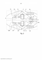
[0023] Nesses desenhos: • a figura 1 é uma vista geral em corte de uma turbomáquina; • a figura 2 é uma vista em corte da parte dianteira de uma turbomáquina equipada com um redutor, que mostra um invólucro frontal de acordo com a arte anterior; • a figura 3 é uma vista em corte da mesma parte dianteira, que mostra um invólucro frontal de acordo com um modo de realização da invenção; • a figura 4 é uma vista de detalhe do invólucro da figura 3, que mostra os meios de acionamento do redutor; e • a figura 5 é uma vista de detalhe dos meios de acionamento da figura 4.[0023] In these drawings: • Figure 1 is a general sectional view of a turbomachine; • figure 2 is a sectional view of the front part of a turbomachine equipped with a reducer, showing a front housing according to the prior art; • figure 3 is a sectional view of the same front part, showing a front housing according to an embodiment of the invention; • figure 4 is a detail view of the housing of figure 3, which shows the drive means of the reducer; and • figure 5 is a detail view of the actuating means of figure 4.
[0024] Fazendo-se referência à figura 1, é visto um turborreator 1 da arte anterior, sem redutor, que compreende, de maneira clássica, uma ventoinha S, um compressor de baixa pressão 1a, um compressor de alta pressão 1b, uma câmara de combustão 1c, uma turbina de alta pressão 1d e uma turbina de baixa pressão 1e. O compressor de alta pressão 1b e a turbina de alta pressão 1d são ligados por um eixo de alta pressão 5 e formam com ele um corpo de alta pressão (AP). O compressor de baixa pressão 1a e a turbina de baixa pressão 1e são ligados por um eixo de baixa pressão 4 e formam com ele um corpo de baixa pressão (BP). A ventoinha é, no que lhe diz respeito, levada por um eixo de ventoinha 3 que, no exemplo representado, é rigidamente fixada no eixo de BP 4, sem dispositivo de redução de velocidade de rotação entre os dois eixos.[0024] Referring to figure 1, a turboreactor 1 of the prior art, without gearbox, is seen, which classically comprises a fan S, a
[0025] Os eixos de AP e de BP se estendem de acordo com um eixo que é o eixo de rotação do turborreator 1. Na sequência da descrição, as noções de longitudinal ou radial, e de interior ou exterior, são relativas a esse eixo.[0025] The axes of AP and BP extend according to an axis that is the axis of rotation of the turbojet 1. Following the description, the notions of longitudinal or radial, and of interior or exterior, are relative to this axis .
[0026] A turbomáquina 1 compreende também, classicamente, um cárter intermediário 2 e um cárter de escape 6 que sustentam, entre outras coisas, os mancais dos eixos de rotação de BP e de AP. Esses últimos são contidos respectivamente, dentro de um invólucro frontal E1 ligado ao cárter intermediário 2, para os mancais situados a montante do corpo de AP, e dentro de um invólucro traseiro E2 ligado ao cárter de escape 6, para os mancais situados a jusante do corpo de AP. O invólucro frontal E1 é delimitado, para sua parte fixa, por cárteres, ditos suportes de mancais, que se estendem na direção do interior do motor, de um lado e de outro do rolamento de batente do eixo de BP e, para sua parte móvel pela extremidade a montante do próprio eixo de BP.[0026] The turbomachine 1 also classically comprises an
[0027] A figura 2 mostra a parte dianteira de um turbofan da arte anterior, no qual um redutor 7 é posicionado entre o eixo de ventoinha 3 e o eixo de BP 4. Esse redutor, a priori de tipo epicicloidal, é representado sob a forma esquemática de um retângulo que só mostra seu volume. Ele é acionado por uma coroa de acionamento 8 que se estende a montante do eixo de BP 4 e que é ligada ao anel móvel do mancal 10 que leva esse eixo de BP. O torque na saída desse redutor 7 é transmitido ao eixo de ventoinha 3, por uma ligação clássica, conhecida pelo profissional, como por exemplo uma fixação desse eixo de ventoinha no porta-satélites, no caso de um redutor epicicloidal. O redutor é colocado no interior de um invólucro frontal E1 de lubrificação, representado em cinzento na figura.[0027] Figure 2 shows the front part of a turbofan of the prior art, in which a
[0028] Nessa versão da arte anterior, a parte fixa do invólucro E1 é formada peã parede interna 21 do percurso de escoamento do fluxo primário, por um suporte a montante de mancal 22 e por uma parede que envolve o suporte frontal de mancal 23. Esse suporte 22 e essa parede 23 se estendem na direção do interior da turbomáquina indo envolver, por um lado, o rolamento do maçal de batente 10 do corpo de BP 4, e, por outro lado, os rolamentos dos mancais 11 e 12 do eixo de ventoinha 3. A parte móvel é, no que lhe diz respeito, formada por uma parede de estanqueidade 128 posicionada na extremidade a montante do eixo de ventoinha 3 e pelos anéis móveis, por um lado, do rolamento de mancal 12 do eixo de ventoinha 3 que é situado o mais a montante e, por outro lado, do mancal de batente 10 do eixo de BP 4 à jusante. A estanqueidade do invólucro E1 é completada à jusante por uma porca de turbina 114 que fixa o eixo de ventoinha 3 e o módulo maior de compressão de baixa pressão no eixo de BP 4. É compreendido desde então que com essa configuração, um desmonte do eixo de BP e sua dessolidarização do primeiro módulo maior, só podem ser efetuados destruindo-se a estanqueidade do invólucro a montante E1.[0028] In this version of the prior art, the fixed part of the housing E1 is formed by the
[0029] A figura 3 mostra a parte dianteira de um turbofan com um invólucro E1 que é melhorado de acordo com a invenção. Sua parte fixa permanece formada pelas mesmas paredes que na versão precedente. No que diz respeito a sua parte móvel, ela é formada, de a montante para a jusante, pelo eixo de ventoinha 3 na qual são fixados os anéis móveis dos rolamentos de batente 11 e de rolos 12 do eixo de ventoinha, por um cárter 28 de extensão a jusante do eixo de ventoinha 3, pela coroa 8 de acionamento do redutor 7 e por um eixo intermediário 9 de extensão da coroa de acionamento, que vem se fixar sobre o anel móvel 26 do rolamento de batente 10 do eixo de BP 4. O invólucro frontal E1 apresenta assim a forma de uma coroa vazada que é centrada no eixo dos eixos de rotação, e não mais uma forma substancialmente convexa que engloba esse eixo. A necessidade de uma parede de estanqueidade à montante do eixo de ventoinha não se mostra assim mais necessária. A estanqueidade do invólucro entre suas partes fixas e suas partes móveis é nesse caso assegurada por 3 estanqueidades: duas estanqueidades de tipo rotor/estator nas extremidades a montante e a jusante, ao nível do mancal de rolos 12 do eixo de ventoinha e do mancal de batente 10 do eixo de BP, e uma estanqueidade de tipo rotor/rotor entre o cárter de extensão 28 e a coroa 8 de acionamento do redutor.[0029] Figure 3 shows the front part of a turbofan with an E1 housing that is improved in accordance with the invention. Its fixed part remains formed by the same walls as in the previous version. As regards its movable part, it is formed, from upstream to downstream, by the
[0030] As partes fixas e móveis do invólucro frontal se unem classicamente ao nível de duas juntas labirinto (ou de outras estanqueidades tecnicamente mais avançadas), que são referenciadas 30 à montante e 31 à jusante e que são posicionadas em suas extremidades de modo a formar um volume estanque que contém os três rolamentos mencionados acima e que assegura a permanência de lubrificação e o resfriamento dos mesmos. Em especial, a estanqueidade entre a coroa 8, que gira na velocidade de eixo de BP 4, e o cárter a jusante de extensão 28, que gira na velocidade do eixo de ventoinha 3, é realizada por uma junta labirinto móvel de estanqueidade 29. Essa junta labirinto móvel 29 assegura a estanqueidade à montante da coroa 8. De modo típico, essa junta labirinto móvel 29 compreende rebordos anulares externos levados pela coroa 8 e circundados com uma pequena folga radial pelo cárter a jusante de extensão 28, como está visível nos desenhos.[0030] The fixed and movable parts of the front casing are classically joined at the level of two labyrinth joints (or other technically more advanced seals), which are referenced 30 upstream and 31 downstream and which are positioned at their ends so as to form a watertight volume that contains the three bearings mentioned above and that ensures their lubrication and cooling. In particular, the sealing between the
[0031] É notado que esse invólucro E1 é inteiramente levado pelo módulo de ventoinha, pelo cárter intermediário e pelo módulo do compressor de BP, o que com que ele possa ser dessolidarizado dos outros módulos assim como do eixo de BP 4, sem que o óleo que está contido nele escape. Por outro lado os diâmetros da coroa de acionamento 8 do redutor e do eixo intermediária 9 do eixo de BP são definidos para serrem superiores àquela do eixo de BP 4, o que significa que é possível introduzir aí uma ferramenta cilíndrica para atingir a porca de fixação do eixo de BP 4 no anel móvel 26 de seu rolamento de batente 10 e permitir seu desatarraxamento sem que essas duas peças interfiram.[0031] It is noted that this E1 housing is entirely carried by the fan module, the intermediate crankcase and the LP compressor module, so that it can be desolidarized from the other modules as well as from the
[0032] A figura 4 mostra mais em detalhe a parte móvel do invólucro E1 que é levada pelo rolamento de batente 10 e pelos dois anéis fixo 25 e móvel 26 desse último. Partindo-se de a jusante, o eixo de BP 4 engrena, por um sistema de caneluras, em um munhão 13, que é ligado ao anel móvel 26 do rolamento de batente 10 por intermédio do eixo intermediária 9, e que gira para acionar o rotor do compressor de BP. O eixo de BP 4 é mantida no lugar, axialmente, sob esse munhão por intermédio de uma porca de união 14 que é atarraxada em um rosqueamento feito na face interna do eixo de BP 4 e que vem se apoiar contra um batente axial 15 que se alarga na direção do interior a partir do munhão 13. Essa porca, que fixa o eixo de BP 4 ao munhão 13, é acessível a partir da parte da frente do motor, mediante no entanto o desmonte prévio do capô de sua ponta dianteira, sem que haja necessidade de desmontar outras peças e notadamente elementos constitutivos das paredes do invólucro E1. O objetivo principal da invenção, a saber a possibilidade de desmontar o eixo de BP sem desmontar o invólucro E1, é assim atingido.[0032] Figure 4 shows in more detail the movable part of the casing E1 that is carried by the stop bearing 10 and by the two fixed
[0033] O munhão 13 leva, na direção de a montante, o eixo intermediário 9 que forma uma extensão da coroa de acionamento 8 do redutor e que é situada radialmente entre o munhão 13 e o anel móvel 26 do rolamento de batente 10 do eixo de BP à qual ela está rigidamente ligada. Esse eixo intermediário tem como objeto prolongar a coroa 8 e permitir o desmonte dessa última do munhão 13, sem que essa separação da coroa em dois elementos distintos, uma coroa propriamente dita 8 e um eixo intermediário 9, seja essencial para a realização da invenção. A extremidade a jusante do eixo intermediário posicionado em torno do eixo de BP 4 constitui, com a coroa de acionamento 8, um elemento de parede do invólucro frontal E1 que é destacável do eixo de BP 4 mas que pode permanecer no lugar e manter a integridade volúmica do invólucro frontal E1 quando o eixo E1 é retirado.[0033] The
[0034] Finalmente a coroa 8 de acionamento do redutor é montada no eixo intermediário 9 por meio de caneluras que fazem operar juntas os dois eixos e que permitem o acionamento da coroa 8, e portanto do redutor 7, pelo eixo de BP 4. Ela tem como indicado precedentemente, um diâmetro superior àquele do eixo de BP 4.[0034] Finally, the
[0035] A figura 5 mostra a união da coroa 8 de acionamento do redutor 7 e do eixo intermediário 9 que lhe transmite o torque fornecido pelo eixo de BP 4. O conjunto dos dois eixos é levado pelo anel móvel 26 do mancal de rolamento de batente 10 através do qual passa a extremidade a jusante do eixo intermediário 9. Essa última é mantida em apoio contra um ressalto do munhão 13, situado a jusante do rolamento de batente, pela ação de uma porca de travamento 16 que é atarraxada em um rosqueamento feito na parede exterior do munhão 13. O eixo intermediário 9 se estende axialmente para a montante apresentando para isso caneluras que operam junto com primeiras caneluras 17 posicionadas na coroa de acionamento 8 em sua extremidade a jusante. A coroa 8 leva por outro lado, justo antes de sua extremidade a montante, segundas caneluras 18 orientada para o exterior, que operam junto com uma roda dentada 27 do redutor 7 que a coroa de acionamento 8 aciona e pelas quais passa o torque de acionamento da ventoinha fornecido pelo eixo BP 4. Finalmente, como indicado precedentemente, a extremidade a montante da coroa de acionamento 8 leva rebordos para formar com o cárter de extensão a jusante 28 uma junta de labirinto de estanqueidade móvel 29 e participar assim para o fechamento do invólucro a montante E1. A coroa de acionamento 8 e o cárter de extensão a jusante são co- rotativos, mas giram, como indicado mais acima, em velocidades diferentes, a coroa de acionamento 8 com seus rebordos girando em maior velocidade, o que contribui para fechar a folga em funcionamento. A ventilação interna à coroa 8 vem, por outro lado, pressurizar o invólucro E1 e evitar os vazamentos de óleo, passando para isso do canal interno ao eixo de ventoinha para o interior do invólucro E1, como está ilustrado por uma flecha na figura 5.[0035] Figure 5 shows the union of the
[0036] Axialmente, a coroa de acionamento 8 é retida em apoio contra o redutor 7 por um aro axial de retenção 19, que é levado por essa coroa e que vem se apoiar contra uma face radial do redutor, de modo que as segundas caneluras 18 estejam bem posicionadas em frente à roda dentada 27 do redutor 7. Em sua extremidade a jusante a coroa de acionamento 8 é enfiada no eixo intermediária 9, que apresenta uma face radial contra a qual pode vir em batente a extremidade a jusante da coroa 8. Uma junta tórica 20 assegura a estanqueidade radial entre as duas peças e uma folga axial é deixada entre a extremidade a jusante da coroa de acionamento 8 e a face radial correspondente do eixo intermediário 9 de modo a permitir dilatações diferenciais eventuais.[0036] Axially, the
[0037] Finalmente um gancho 24 formado por uma série de dentes que se estendem circunferencialmente é posicionado no interior da coroa de acionamento 8 para poder imobilizar em rotação o conjunto das peças móveis do módulo de ventoinha e do módulo de BP quando é desejado desmontar o eixo de BP 4. Uma ferramenta especializada é introduzida, a partir de a montante do motor, no cilindro interno vazado do eixo de ventoinha 3, que vem se apoiar sobre o gancho 24 para impedir a rotação dos rotores de ventoinha e de BP enquanto ela introduz, em sua extremidade, a porca de união 14 para desatarraxar a mesma e liberar o eixo de BP 4.[0037] Finally, a
[0038] No final a invenção se caracteriza pela presença de uma ou vários eixos de acionamento do redutor 7 que não é nesse caso mais levada pelo eixo de BP 4 mas que o é, ou diretamente, ou por razões de facilidade de desmonte via um eixo intermediário 9, pelo anel móvel 26 do mancal de batente desse eixo de BP. É nesse caso possível, preparando-se as necessárias estanqueidades entre peças fixas e peças móveis e entre peças móveis co-rotativas, organizar um invólucro frontal E1 que compreende um redutor, do qual nenhuma parede não é mais diretamente ligada ao eixo de BP 4. O desmonte desse último pode nesse caso ser efetuado sem que se faça um esvaziamento do óleo situado dentro da cavidade do invólucro frontal E1.[0038] In the end, the invention is characterized by the presence of one or more drive shafts of the
[0039] Como indicado precedentemente, por razões de acessibilidade à porca de união 14 do eixo de BP, o ou os eixos de acionamento do redutor 7, que formam assim a parede interna do invólucro, têm um diâmetro superior àquele da dita porca, de modo a deixar a passagem para uma ferramenta especializada.[0039] As previously indicated, for reasons of accessibility to the
Claims (9)
Applications Claiming Priority (3)
| Application Number | Priority Date | Filing Date | Title |
|---|---|---|---|
| FR1361468 | 2013-11-21 | ||
| FR1361468A FR3013385B1 (en) | 2013-11-21 | 2013-11-21 | PRE-SEALED SPEAKER DURING MODULAR DISASSEMBLY OF A REDUCING TURBOREACTOR |
| PCT/FR2014/052899 WO2015075355A1 (en) | 2013-11-21 | 2014-11-13 | Front enclosure which is sealed during the modular dismantling of a turbojet with reduction gear |
Publications (2)
| Publication Number | Publication Date |
|---|---|
| BR112016010628A2 BR112016010628A2 (en) | 2017-08-08 |
| BR112016010628B1 true BR112016010628B1 (en) | 2022-02-01 |
Family
ID=50069150
Family Applications (1)
| Application Number | Title | Priority Date | Filing Date |
|---|---|---|---|
| BR112016010628-8A BR112016010628B1 (en) | 2013-11-21 | 2014-11-13 | DUAL FLOW TURBOREACTOR INCLUDING A FAN |
Country Status (8)
| Country | Link |
|---|---|
| US (1) | US10422341B2 (en) |
| EP (1) | EP3071802B1 (en) |
| CN (1) | CN105745400B (en) |
| BR (1) | BR112016010628B1 (en) |
| CA (1) | CA2929798C (en) |
| FR (1) | FR3013385B1 (en) |
| RU (1) | RU2674837C1 (en) |
| WO (1) | WO2015075355A1 (en) |
Families Citing this family (22)
| Publication number | Priority date | Publication date | Assignee | Title |
|---|---|---|---|---|
| FR3022890B1 (en) * | 2014-06-25 | 2018-01-05 | Snecma | TURBOMACHINE COMPRISING A MEANS FOR DECOUPLING A BLOWER |
| US10119465B2 (en) | 2015-06-23 | 2018-11-06 | United Technologies Corporation | Geared turbofan with independent flexible ring gears and oil collectors |
| GB201704045D0 (en) * | 2017-03-14 | 2017-04-26 | Rolls Royce Plc | A seal panel for gas turbine engine |
| US10823001B2 (en) * | 2017-09-20 | 2020-11-03 | General Electric Company | Turbomachine with alternatingly spaced turbine rotor blades |
| FR3075861B1 (en) | 2017-12-22 | 2019-11-15 | Safran Aircraft Engines | DYNAMIC SEAL BETWEEN TWO ROTORS OF AN AIRCRAFT TURBOMACHINE |
| FR3075860B1 (en) | 2017-12-22 | 2019-11-29 | Safran Aircraft Engines | DYNAMIC SEAL BETWEEN TWO ROTORS OF AN AIRCRAFT TURBOMACHINE |
| US11199103B2 (en) * | 2018-09-06 | 2021-12-14 | General Electric Company | Seal assembly for a turbomachine |
| FR3086343B1 (en) * | 2018-09-24 | 2020-09-04 | Safran Aircraft Engines | TURBOMACHINE WITH REDUCER FOR AN AIRCRAFT |
| FR3087226B1 (en) * | 2018-10-10 | 2020-10-23 | Safran Aircraft Engines | AIRCRAFT TURBOMACHINE WITH MECHANICAL REDUCER AND CONTRAROTATING TURBINE |
| FR3087823B1 (en) * | 2018-10-26 | 2020-11-13 | Safran Aircraft Engines | BLOWER MODULE EQUIPPED WITH AN ELECTRIC MACHINE FOR AN AIRCRAFT TURBOMACHINE |
| DE102019102429A1 (en) * | 2019-01-31 | 2020-08-06 | Rolls-Royce Deutschland Ltd & Co Kg | Gas turbine engine for an aircraft |
| FR3100050B1 (en) | 2019-08-19 | 2021-07-23 | Safran Aircraft Engines | OIL DISTRIBUTION DEVICE OF AN AIRCRAFT TURBOMACHINE BEARING BEARING |
| FR3104207B1 (en) * | 2019-12-10 | 2021-11-05 | Safran Aircraft Engines | PRESSURIZATION OF LUBRICATION ENCLOSURES IN A TURBOMACHINE WITH CONTRAROTARY TURBINE |
| JP7445453B2 (en) * | 2020-02-14 | 2024-03-07 | 川崎重工業株式会社 | gas turbine engine |
| FR3107310B1 (en) | 2020-02-17 | 2022-01-14 | Safran Aircraft Engines | AIRCRAFT TURBOMACHINE BEARING OIL DISTRIBUTION DEVICE |
| FR3108935B1 (en) | 2020-04-02 | 2022-03-04 | Safran Aircraft Engines | AIRCRAFT TURBOMACHINE BEARING OIL DISTRIBUTION DEVICE |
| US11629649B2 (en) * | 2020-05-11 | 2023-04-18 | Raytheon Technologies Corporation | Gas turbine engine with speed sensor |
| CN114542290A (en) * | 2020-11-26 | 2022-05-27 | 中国航发商用航空发动机有限责任公司 | Support structure of engine |
| FR3118993B1 (en) | 2021-01-15 | 2022-12-30 | Safran Aircraft Engines | BLOWER MODULE INCLUDING ENHANCED SEAL MEANS OF A LUBRICANT ENCLOSURE |
| US11668247B2 (en) * | 2021-04-16 | 2023-06-06 | Raytheon Technologies Corporation | Geared gas turbine with oil scavenge ejector pump assist |
| CN114962427B (en) * | 2022-06-30 | 2023-09-26 | 中国航发贵阳发动机设计研究所 | Structure for realizing multidirectional transmission of engine rotor by double transmission shafts |
| FR3140124A1 (en) * | 2022-09-26 | 2024-03-29 | Safran Aircraft Engines | TURBOMACHINE COMPRISING SEVERAL MODULES AND A DEVICE FOR BLOCKING THESE MODULES, AND CORRESPONDING DISASSEMBLY METHOD |
Family Cites Families (37)
| Publication number | Priority date | Publication date | Assignee | Title |
|---|---|---|---|---|
| FR1251656A (en) | 1960-03-18 | 1961-01-20 | Fitting for plastic and other pipes | |
| FR2614073B1 (en) * | 1987-04-15 | 1992-02-14 | Snecma | REAL-TIME ADJUSTMENT DEVICE OF THE RADIAL GAME BETWEEN A ROTOR AND A TURBOMACHINE STATOR |
| US6158210A (en) * | 1998-12-03 | 2000-12-12 | General Electric Company | Gear driven booster |
| DE102004042739A1 (en) * | 2004-09-03 | 2006-03-09 | Mtu Aero Engines Gmbh | Fan for an aircraft engine and aircraft engine |
| WO2006059970A2 (en) * | 2004-12-01 | 2006-06-08 | United Technologies Corporation | Turbine engine with differential gear driven fan and compressor |
| US7493753B2 (en) * | 2005-10-19 | 2009-02-24 | General Electric Company | Gas turbine engine assembly and methods of assembling same |
| DE102006003692B3 (en) * | 2006-01-26 | 2007-08-16 | Tyco Electronics Amp Gmbh | Clock spring |
| US7704178B2 (en) * | 2006-07-05 | 2010-04-27 | United Technologies Corporation | Oil baffle for gas turbine fan drive gear system |
| US8858388B2 (en) * | 2006-08-15 | 2014-10-14 | United Technologies Corporation | Gas turbine engine gear train |
| US9976437B2 (en) * | 2006-08-15 | 2018-05-22 | United Technologies Corporation | Epicyclic gear train |
| US7661260B2 (en) * | 2006-09-27 | 2010-02-16 | General Electric Company | Gas turbine engine assembly and method of assembling same |
| US7726021B2 (en) * | 2006-09-28 | 2010-06-01 | Pratt & Whitney Canada Corp. | Labyrinth seal repair |
| US7966806B2 (en) * | 2006-10-31 | 2011-06-28 | General Electric Company | Turbofan engine assembly and method of assembling same |
| US20140165534A1 (en) * | 2007-09-21 | 2014-06-19 | United Technologies Corporation | Gas turbine engine compressor arrangement |
| US7955046B2 (en) * | 2007-09-25 | 2011-06-07 | United Technologies Corporation | Gas turbine engine front architecture modularity |
| US8205432B2 (en) * | 2007-10-03 | 2012-06-26 | United Technologies Corporation | Epicyclic gear train for turbo fan engine |
| US9784181B2 (en) * | 2009-11-20 | 2017-10-10 | United Technologies Corporation | Gas turbine engine architecture with low pressure compressor hub between high and low rotor thrust bearings |
| US8672801B2 (en) * | 2009-11-30 | 2014-03-18 | United Technologies Corporation | Mounting system for a planetary gear train in a gas turbine engine |
| US8997500B2 (en) * | 2010-02-19 | 2015-04-07 | United Technologies Corporation | Gas turbine engine oil buffering |
| US8777793B2 (en) * | 2011-04-27 | 2014-07-15 | United Technologies Corporation | Fan drive planetary gear system integrated carrier and torque frame |
| EP2535528B1 (en) * | 2011-06-17 | 2021-04-28 | Raytheon Technologies Corporation | Turbofan engine bearing support |
| US9416677B2 (en) * | 2012-01-10 | 2016-08-16 | United Technologies Corporation | Gas turbine engine forward bearing compartment architecture |
| US9004849B2 (en) * | 2012-01-10 | 2015-04-14 | United Technologies Corporation | Gas turbine engine forward bearing compartment architecture |
| US10400629B2 (en) * | 2012-01-31 | 2019-09-03 | United Technologies Corporation | Gas turbine engine shaft bearing configuration |
| US8402741B1 (en) * | 2012-01-31 | 2013-03-26 | United Technologies Corporation | Gas turbine engine shaft bearing configuration |
| US9038366B2 (en) * | 2012-01-31 | 2015-05-26 | United Technologies Corporation | LPC flowpath shape with gas turbine engine shaft bearing configuration |
| US9115598B2 (en) * | 2012-06-05 | 2015-08-25 | United Technologies Corporation | Front bearing support for a fan drive gear system |
| US9896968B2 (en) * | 2012-07-30 | 2018-02-20 | United Technologies Corporation | Forward compartment baffle arrangement for a geared turbofan engine |
| US9234439B2 (en) * | 2012-11-01 | 2016-01-12 | United Technologies Corporation | Gas turbine engine with bearing compartment wall cooling |
| US10605112B2 (en) * | 2013-03-04 | 2020-03-31 | United Technologies Corporation | Fan drive gear system spline oil lubrication scheme |
| EP3004595B1 (en) * | 2013-06-03 | 2020-09-02 | United Technologies Corporation | Turbofan engine bearing and gearbox arrangement |
| BR112016002022A2 (en) * | 2013-08-16 | 2017-08-01 | Gen Electric | flow swirl spoiler |
| EP3036410B1 (en) * | 2013-08-21 | 2018-06-06 | United Technologies Corporation | Integral gutter and front center body |
| FR3013388B1 (en) * | 2013-11-21 | 2019-03-22 | Safran Aircraft Engines | ENGINE, SUCH AS A TURBOJET, MODULAR WITH SPEED REDUCER |
| GB201417505D0 (en) * | 2014-10-03 | 2014-11-19 | Rolls Royce Deutschland | A gas turbine architecture |
| DE102014119066A1 (en) * | 2014-12-18 | 2016-06-23 | Rolls-Royce Deutschland Ltd & Co Kg | Aero engine with a device for separating oil |
| GB201510050D0 (en) * | 2015-06-10 | 2015-07-22 | Rolls Royce Plc | A geared gas turbine engine |
-
2013
- 2013-11-21 FR FR1361468A patent/FR3013385B1/en active Active
-
2014
- 2014-11-13 US US15/037,151 patent/US10422341B2/en active Active
- 2014-11-13 RU RU2016118994A patent/RU2674837C1/en active
- 2014-11-13 BR BR112016010628-8A patent/BR112016010628B1/en active IP Right Grant
- 2014-11-13 CN CN201480063153.9A patent/CN105745400B/en active Active
- 2014-11-13 CA CA2929798A patent/CA2929798C/en active Active
- 2014-11-13 EP EP14821704.5A patent/EP3071802B1/en active Active
- 2014-11-13 WO PCT/FR2014/052899 patent/WO2015075355A1/en active Application Filing
Also Published As
| Publication number | Publication date |
|---|---|
| CN105745400A (en) | 2016-07-06 |
| FR3013385A1 (en) | 2015-05-22 |
| CN105745400B (en) | 2018-07-03 |
| CA2929798C (en) | 2021-11-16 |
| US10422341B2 (en) | 2019-09-24 |
| WO2015075355A1 (en) | 2015-05-28 |
| BR112016010628A2 (en) | 2017-08-08 |
| EP3071802B1 (en) | 2020-01-01 |
| FR3013385B1 (en) | 2015-11-13 |
| RU2016118994A (en) | 2017-12-26 |
| RU2674837C1 (en) | 2018-12-13 |
| EP3071802A1 (en) | 2016-09-28 |
| CA2929798A1 (en) | 2015-05-28 |
| US20160298639A1 (en) | 2016-10-13 |
Similar Documents
| Publication | Publication Date | Title |
|---|---|---|
| BR112016010628B1 (en) | DUAL FLOW TURBOREACTOR INCLUDING A FAN | |
| JP6407998B2 (en) | Planetary reduction gear with fluid transfer line and aircraft propeller turbomachine with such reduction gear | |
| US10473035B2 (en) | Modular engine, such as a jet engine, with a speed reduction gear | |
| CA2802542C (en) | Oil purge system for a mid turbine frame | |
| JP6367897B2 (en) | Pin arrangement of the power gearbox | |
| RU2689258C2 (en) | Gas turbine plant and its dismantling method | |
| RU2686248C2 (en) | Front part of aircraft double-flow gas turbine engine and aircraft double-flow gas turbine engine | |
| JP2005054781A (en) | Low pressure turbine for turbo machine | |
| JP2006125385A (en) | Gas turbine engine, and method for assembling the same | |
| CN109630218B (en) | Exhaust component of a gas turbine | |
| US3152443A (en) | Gas turbine powerplant | |
| CA2957464C (en) | Sump housing for a gas turbine engine | |
| BR112015031685B1 (en) | INTERMEDIATE CASING FOR TURBO MACHINE, GEARBOX DRIVE ASSEMBLY, TURBOMACHINE AND METHOD FOR ASSEMBLY OF A GEARBOX DRIVE ASSEMBLY | |
| JP2006125386A (en) | Counter-rotating turbine engine, and method for assembling the same | |
| US11725529B2 (en) | Fluid transfer assembly for rotational equipment | |
| EP3670860B1 (en) | Fan and low pressure compressor geared to a low speed spool of a gas turbine engine | |
| US20140010648A1 (en) | Sleeve for turbine bearing stack | |
| JP2016211574A (en) | Intershaft integrated seal and lock-nut | |
| JP2007146755A (en) | Gas turbine | |
| JP2012031861A (en) | Gas turbine engine | |
| RU2669120C2 (en) | Turbine engine maintenance method (embodiments) and the gas turbine engine | |
| US20230399960A1 (en) | Device for pressurizing turbomachine downstream enclosure, and corresponding turbomachine | |
| JP2005009440A (en) | Gas turbine and its assembling method |
Legal Events
| Date | Code | Title | Description |
|---|---|---|---|
| B06U | Preliminary requirement: requests with searches performed by other patent offices: procedure suspended [chapter 6.21 patent gazette] | ||
| B09A | Decision: intention to grant [chapter 9.1 patent gazette] | ||
| B16A | Patent or certificate of addition of invention granted [chapter 16.1 patent gazette] |
Free format text: PRAZO DE VALIDADE: 20 (VINTE) ANOS CONTADOS A PARTIR DE 13/11/2014, OBSERVADAS AS CONDICOES LEGAIS. |