BR112016010339B1 - CAN END WITHOUT FULL OPENING SEAMS, FULL OPENING CAN SET AND CAN END WITHOUT SEAMLESSING - Google Patents
CAN END WITHOUT FULL OPENING SEAMS, FULL OPENING CAN SET AND CAN END WITHOUT SEAMLESSING Download PDFInfo
- Publication number
- BR112016010339B1 BR112016010339B1 BR112016010339-4A BR112016010339A BR112016010339B1 BR 112016010339 B1 BR112016010339 B1 BR 112016010339B1 BR 112016010339 A BR112016010339 A BR 112016010339A BR 112016010339 B1 BR112016010339 B1 BR 112016010339B1
- Authority
- BR
- Brazil
- Prior art keywords
- dotted line
- rivet
- panel
- center
- pair
- Prior art date
Links
- 238000009423 ventilation Methods 0.000 claims abstract description 26
- 230000002093 peripheral Effects 0.000 claims description 19
- 238000009958 sewing Methods 0.000 claims description 3
- 238000001881 scanning electron acoustic microscopy Methods 0.000 claims 4
- 239000000523 sample Substances 0.000 abstract 1
- 235000013361 beverage Nutrition 0.000 description 14
- 229910052751 metal Inorganic materials 0.000 description 8
- 239000002184 metal Substances 0.000 description 8
- 239000011324 bead Substances 0.000 description 5
- 238000000034 method Methods 0.000 description 5
- XAGFODPZIPBFFR-UHFFFAOYSA-N aluminum Chemical compound [Al] XAGFODPZIPBFFR-UHFFFAOYSA-N 0.000 description 4
- 239000002826 coolant Substances 0.000 description 3
- 239000000463 material Substances 0.000 description 3
- 229910001092 metal group alloy Inorganic materials 0.000 description 3
- 229910052782 aluminium Inorganic materials 0.000 description 2
- 235000014171 carbonated beverage Nutrition 0.000 description 2
- 230000000875 corresponding Effects 0.000 description 2
- BVKZGUZCCUSVTD-UHFFFAOYSA-N Carbonic acid Chemical compound OC(O)=O BVKZGUZCCUSVTD-UHFFFAOYSA-N 0.000 description 1
- WEQAYVWKMWHEJO-UHFFFAOYSA-N Chlormezanone Chemical compound O=S1(=O)CCC(=O)N(C)C1C1=CC=C(Cl)C=C1 WEQAYVWKMWHEJO-UHFFFAOYSA-N 0.000 description 1
- 241000405961 Scomberomorus regalis Species 0.000 description 1
- 229910000831 Steel Inorganic materials 0.000 description 1
- 230000004913 activation Effects 0.000 description 1
- 235000013405 beer Nutrition 0.000 description 1
- 230000015572 biosynthetic process Effects 0.000 description 1
- 239000007799 cork Substances 0.000 description 1
- 238000005755 formation reaction Methods 0.000 description 1
- 238000004519 manufacturing process Methods 0.000 description 1
- 150000002739 metals Chemical class 0.000 description 1
- 238000004806 packaging method and process Methods 0.000 description 1
- 230000001902 propagating Effects 0.000 description 1
- 238000000926 separation method Methods 0.000 description 1
- 235000014214 soft drink Nutrition 0.000 description 1
- 239000010959 steel Substances 0.000 description 1
- 230000001629 suppression Effects 0.000 description 1
- 229910052718 tin Inorganic materials 0.000 description 1
- ATJFFYVFTNAWJD-UHFFFAOYSA-N tin hydride Chemical compound [Sn] ATJFFYVFTNAWJD-UHFFFAOYSA-N 0.000 description 1
- 239000005028 tinplate Substances 0.000 description 1
Images


Abstract
MONTAGENS DE LATA DE ABERTURA COMPLETA, E EXTREMOS DE LATA SEM COSTURAS DE ABERTURA COMPLETA, E EXTREMO DE LATA SEM COSTURAS. Um extremo de latas sem costuras de apertura completa que tem uma classificação de proba de ventilação de pelo menos 6,205 kg/cm2 (90 psi) que compreende um painel (24) central que tem uma periferia e que inclui uma parte embutida perto de um rebite (30), uma primeira linha pontilhada (26) que define um painel (34) retirável, um olhal (32), que inclui uma ponta (31), montada no painel (34) retirável, e uma segunda linha pontilhada (40) disposta no painel retirável, a segunda linha pontilhada tem (i) uma parte central (42), separada da parte embutida; (ii) um par de ranhuras (45a, 45b) de comprobação dispostas em qualquer lado da parte central; (iii) um par de partes laterais que estendem- se desde as ranhuras de comprobação; e (iv) um par de partes (50a, 50b) laterais que estendem-se desde as partes laterais, respectivamente.FULL OPENING CAN ASSEMBLIES, AND FULL OPENING CAN END WITHOUT SEAMLESSING, AND WITHOUT SEAMLESSING CAN END. An end of full-aperture seamless cans that have a ventilation test rating of at least 6.205 kg/cm2 (90 psi) that comprises a center panel (24) that has a periphery and that includes a recessed portion near a rivet (30), a first dotted line (26) defining a withdrawable panel (34), an eye (32) including a point (31) mounted to the withdrawable panel (34) and a second dotted line (40) disposed on the pull-out panel, the second dotted line has (i) a central portion (42) separate from the recessed portion; (ii) a pair of evidence grooves (45a, 45b) disposed on either side of the center portion; (iii) a pair of side parts extending from the probe grooves; and (iv) a pair of side parts (50a, 50b) extending from the side parts, respectively.
Description
[001] O presente pedido reivindica o benefício do Pedido de Patente dos Estados Unidos 14/075,299 apresentado no 8 de novembro, 2013 a descrição do cual é totalmente incorporada no presente como referência.[001] The present application claims the benefit of United States
[002] Esta invenção refere-se a recipientes, e mais particularmente aos extremos de latas e latas que têm aberturas de abertura completa e são configuradas para ser usadas em aplicações de alta pressão, tais como as que contêm refrescos e outras bebidas carbonatadas.[002] This invention relates to containers, and more particularly to the ends of cans and cans that have full opening openings and are configured to be used in high pressure applications such as those containing soft drinks and other carbonated beverages.
[003] Os corpos convencionais de latas de bebidas tipicamente produzem-se em grandes quantidades por um processo de estirado e embutimento. Os extremos de latas de bebidas convencionais formam-se numa prensa e depois unem-se ao corpo de lata por uma costura dupla.[003] Conventional beverage can bodies are typically produced in large quantities by a drawing and drawing process. The ends of conventional beverage cans are formed in a press and then joined to the can body by a double seam.
[004] A pressão interna em latas de bebida pode submeter as linhas pontilhadas dos extremos destas latas a forças altas com o acionamento de olhal e a formação posterior de gretas nas linhas pontilhadas. Em algumas circunstancias, as altas pressões internas podem provocar ruptura súbita, insegura de linhas pontilhadas ou falha do painel (por exemplo, mal alinhamento) com a abertura.[004] The internal pressure in beverage cans can subject the dotted lines of the ends of these cans to high forces with the actuation of the eye and the subsequent formation of cracks in the dotted lines. In some circumstances, high internal pressures can cause sudden, unsafe breakage of dotted lines or panel failure (eg, misalignment) to open.
[005] Para lograr uma ventilação segura em latas de bebida pressurizadas convencionais com aberturas que têm um área menor que é a maior parte do painel central (tais como em latas de bebidas de 350 ml (12 onças) convencionais), os fabricantes de latas tipicamente empregam uma característica que passa a propagação duma linha pontilhada só que define o perímetro da abertura. As linhas pontilhadas originais para latas de bebida normalmente têm uma ranhura de comprovação para pausar a propagação da linha pontilhada. Uma ranhura de comprovação é uma linha, pontilhada residual (é dizer, o metal na parte inferior da linha pontilhada) que é mais grossa que outras porções da linha pontilhada. Por causa do que a linha pontilhada residual é mais grossa, a ranhura de comprovação inibe a propagação da ruptura da linha pontilhada de modo que uma parte da pressão interna é ventilada antes de que o reste da linha pontilhada se quebre. Desta maneira, para extremos de bebida convencionais, ranhuras de comprovação retardam ou pausam a propagação da linha pontilhada para dar uma ventilação adequada antes no processo de abertura.[005] To achieve safe ventilation in conventional pressurized beverage cans with openings that have a smaller area than most of the center panel (such as in conventional 350 ml (12 oz) beverage cans), can manufacturers typically employ a feature that passes the propagation of a dotted line but defines the perimeter of the opening. Original dotted lines for beverage cans typically have a preflight groove to pause the dotted line from propagating. A preflight groove is a residual, dotted line (that is, the metal at the bottom of the dotted line) that is thicker than other portions of the dotted line. Because the residual dotted line is thicker, the test groove inhibits propagation of dotted line breakage so that some of the internal pressure is vented before the rest of the dotted line breaks. In this way, for conventional beverage ends, proofing grooves delay or pause the dotted line propagation to provide adequate ventilation prior to the opening process.
[006] As latas de bebidas com aberturas que têm áreas maiores que a maior parte do painel central, tais como extremos de abertura completa, também são conhecidas. A Patente dos Estados Unidos Número 7,922,025 (Heinicke) dirige-se a ventilar latas que têm pressão interna de 1,757 kg/cm2 (25 psi) ou mais, tais como as que encontram-se algumas vezes em embalagem de nozes e outros artigos alimentícios, bolas de tênis e similares. De maneira similar, as Publicações dos Estados Unidos Nos. 2011/0056945A1 (”Ramsey”) e 2011/0303672A1 (”Fields”) descrevem a ventilação de latas que têm pressão interna de mais de 4,921 kg/cm2 (70 psi). No entanto, a estrutura mostrada em Heinicke não é adequada para aplicações de pressão muito alta, tais como latas de refrescantes. Além disso, os extremos descritos em Ramsey e Fields ainda não são muito adotados comercialmente. Existe necessidade de solidez melhorada de latas de refrescante, que tipicamente têm classificações de prova de ventilação de pelo menos 6,205 kg/cm2 (90 psi).[006] Beverage cans with openings that have areas larger than most of the center panel, such as full-open ends, are also known. United States Patent Number 7,922,025 (Heinicke) is directed to venting cans that have an internal pressure of 1,757 kg/cm2 (25 psi) or more, such as are sometimes found in the packaging of nuts and other food items, tennis balls and the like. Similarly, United States Publications Nos. 2011/0056945A1 (“Ramsey”) and 2011/0303672A1 (“Fields”) describe venting cans that have an internal pressure of more than 4.921 kg/cm2 (70 psi). However, the structure shown in Heinicke is not suitable for very high pressure applications such as coolant cans. Furthermore, the extremes described in Ramsey and Fields are still not widely adopted commercially. There is a need for improved strength of coolant cans, which typically have vent proof ratings of at least 6.205 kg/cm2 (90 psi).
[007] O pensamento convencional para ventilar extremos de latas de abertura completa tem sido controlar, especialmente quando inibido de forma temporal o desacelerar, a propagação de rupturas de linha pontilhada por características que impedirem de forma mecânica a ruptura de linhas pontilhadas, incrementando a linha pontilhada residual nos extremos de latas de alimentos, e as linhas pontilhadas de corte em Heinicke. Os pedidos de Ramsey e Fields contradizerem este pensamento ao ensinar que uma linha pontilhada de ventilação que não tem um mecanismo de supressão vai se quebrar mais rápido, de modo que uma abertura que tem suficiente área criada por tal linha pontilhada de ventilação libera pressões altas internas na lata antes que essas pressões possuam a possibilidade de quebrar o extremo de lata. Neste contexto, a ventilação mencionada neste pedido é ventilar a pressão interna de lata de bebida com a abertura, como é distinguido duma ventilação que se abre depois de que pressão interna tem se liberado e tem o objetivo de melhorar o vertido.[007] The conventional thinking to ventilate the extremes of full opening cans has been to control, especially when temporarily inhibited or slowing down, the propagation of dotted line breaks by characteristics that mechanically prevent the break of dotted lines, increasing the line dotted residual on the ends of food cans, and the dotted lines cut in Heinicke. Ramsey and Fields' claims contradict this thinking by teaching that a dotted line of vent that does not have a suppression mechanism will break faster, so that an opening that has sufficient area created by such a dotted line of vent releases high internal pressures. in the can before these pressures have the possibility of breaking the can end. In this context, the vent mentioned in this application is to vent the internal pressure of the beverage can with the opening, as distinguished from a vent that opens after internal pressure has been released and is intended to improve pouring.
[008] A presente invenção descreve uma forma inovadora de ventilar latas de bebida de pressão alta com extremos de abertura completa. Embora a técnica anterior tal como Heinicke descreve mecanismos de controle para minimizar o desprendimento no extremo de lata, e as novas referências Ramsey e Fields ensinam a evasão de mecanismos de controle, a invenção reclamada aparta-se destes conceptos conhecidos. Especificamente, a invenção reclamada emprega uma geometria única no que se refere à proximidade de uma parte central da linha pontilhada de ventilação por acima de 6,205 kg/cm2 (90 psi).[008] The present invention describes an innovative way to vent high pressure beverage cans with full opening ends. Although prior art such as Heinicke describes control mechanisms to minimize can-end sag, and new references Ramsey and Fields teach evasion of control mechanisms, the claimed invention departs from these known concepts. Specifically, the claimed invention employs a unique geometry with regard to proximity to a central portion of the vent dotted line above 6.205 kg/cm2 (90 psi).
[009] Sem importar a necessidade de à muito tempo na industria de ter latas de soda de abertura grande, os extremos de abertura completa não tem sido comercialmente exitosos. A invenção descobriu simplesmente que um cambio na geometria da linha pontilhada de ventilação mostrada em Fields pode resultar numa parte de prova de ventilação que é de 0,562 kg/cm2 (8 psi), maior do que aqueles conhecidos na técnica anterior.[009] Regardless of the long-standing need in the industry to have large opening soda cans, the extremes of full opening have not been commercially successful. The invention has simply discovered that a change in the vent dotted line geometry shown in Fields can result in a vent test piece that is 0.562 kg/cm2 (8 psi), greater than those known in the prior art.
[010] Uma montagem de lata de abertura completa que tem uma classificação de prova de ventilação de pelo menos 6,205 kg/cm2 (90 psi) compreende um corpo de lata e um extremo de lata que se conecta ao corpo de lata mediante uma costura. O extremo de lata inclui um painel que tem uma periferia e que inclui una parte embutida próxima dum rebite, uma primeira linha pontilhada disposta perto da periferia do painel central, a primeira linha pontilhada define um painel retirável, um olhal, que inclui uma ponta, montada no painel retirável pelo rebite de modo que a ponta é disposta perto da primeira linha pontilhada, o olhal estende-se ao largo dum eixo longitudinal que é perpendicular a um eixo lateral que também estende-se pelo centro do rebite, e uma segunda linha pontilhada disposta no painel retirável, a segunda linha pontilhada tem (i) uma parte central separada da parte embutida que entrecruza o eixo longitudinal, (ii) um par de ranhuras de comprovação dispostas no lado da parte central; (iii) um par de partes laterais que estendem-se desde as ranhuras de comprovação, respectivamente, e cada uma inclui um segmento que é aproximadamente paralelo ao eixo longitudinal; e (iv) um par de partes laterais que estendem-se desde as partes laterais, respectivamente, afastadas do eixo lateral.[010] A full opening can assembly that has a ventilation proof rating of at least 6.205 kg/cm2 (90 psi) comprises a can body and a can end that attaches to the can body through a seam. The can end includes a panel that has a periphery and that includes a recessed portion proximate a rivet, a first dotted line disposed near the periphery of the center panel, the first dotted line defines a peelable panel, an eye, that includes a tip, mounted on the removable panel by the rivet so that the point is disposed near the first dotted line, the eye extends along a longitudinal axis which is perpendicular to a lateral axis which also extends through the center of the rivet, and a second line dotted line disposed on the pull-out panel, the second dotted line has (i) a central portion separate from the recessed portion that crisscrosses the longitudinal axis, (ii) a pair of evidence grooves disposed on the side of the central portion; (iii) a pair of side portions extending from the proving grooves, respectively, and each including a segment that is approximately parallel to the longitudinal axis; and (iv) a pair of side parts extending from the side parts, respectively, away from the lateral axis.
[011] Um extremo de lata sem costura de abertura completa que tem uma classificação de prova de ventilação de pelo menos 6,205 kg/cm2 (90 psi) compreende um reborde periférico com capacidade de costura junto com uma flange de corpo de lata, uma parede que estende-se internamente e para baixo do reborde periférico, um painel central que tem uma periferia e que inclui uma parte embutida perto dum rebite, uma primeira linha pontilhada disposta perto da periferia do painel central, a primeira linha pontilhada define um painel retirável, um olhal, que inclui uma ponta, montada no painel retirável pelo rebite de modo que a ponta é disposta perto da primeira linha pontilhada, o olhal estende-se ao largo dum eixo longitudinal que é perpendicular a um eixo lateral que também estende-se pelo centro do rebite, e uma segunda linha pontilhada disposta no painel retirável, a segunda linha pontilhada tem (i) uma parte central separada da parte embutida que entrecruza o eixo longitudinal, (ii) um par de ranhuras de comprovação dispostas no qualquer lado da parte central; (iii) um par de partes laterais que estendem-se desde as ranhuras de comprovação, respectivamente, e cada uma inclui um segmento que é aproximadamente paralelo ao eixo lateral; e (iv) um par de partes laterais que estendem-se desde as partes laterais, respectivamente, afastadas do eixo longitudinal.[011] A full-opening seamless can end that has a ventilation proof rating of at least 6.205 kg/cm2 (90 psi) comprises a seam-capable peripheral rim along with a can body flange, a wall extending inwardly and below the peripheral edge, a center panel having a periphery and including a recessed portion near a rivet, a first dotted line disposed near the periphery of the center panel, the first dotted line defines a pull-out panel, an eye, which includes a point, mounted on the panel removable by the rivet so that the point is disposed near the first dotted line, the eye extends along a longitudinal axis that is perpendicular to a side axis that also extends through the center of the rivet, and a second dotted line disposed on the pull-out panel, the second dotted line has (i) a central portion separate from the recessed portion that crisscrosses the longitudinal axis, (ii) a pair of proof slots arranged on either side of the center portion; (iii) a pair of side portions extending from the proving grooves, respectively, and each including a segment that is approximately parallel to the side axis; and (iv) a pair of side parts extending from the side parts, respectively, away from the longitudinal axis.
[012] Uma montagem de lata de abertura completa que tem uma classificação de proba de ventilação de pelo menos 6,205 kg/cm2 (90 psi) compreende um corpo de lata e um extremo de lata que se conecta ao corpo de lata mediante uma costura. O extremo de lata inclui um painel que tem uma periferia, uma primeira linha pontilhada disposta perto da periferia do painel central, a primeira linha pontilhada define um painel retirável, um olhal, que inclui uma ponta, montada no painel retirável pelo rebite de modo que a ponta é disposta perto da primeira linha pontilhada, o olhal estende-se ao largo dum eixo longitudinal que é perpendicular a um eixo lateral que também estende-se pelo centro do rebite, e uma segunda linha pontilhada disposta no painel retirável, a segunda linha pontilhada tem (i) uma parte central definida por um radio que estende-se desde o centro do rebite, o radio tem um valor de pelo menos 3,56 milímetros (0,140 polegadas), a parte central que entrecruza o eixo longitudinal; (ii) um par de ranhuras de comprovação dispostas no qualquer lado da parte central; (iii) um par de partes laterais que estendem-se desde as ranhuras de comprovação, respectivamente, e cada uma inclui um segmento que é aproximadamente paralelo ao eixo longitudinal; e (iv) um par de partes laterais que estendem-se desde as partes laterais, respectivamente, afastadas do eixo lateral.[012] A full opening can assembly that has a ventilation test rating of at least 6.205 kg/cm2 (90 psi) comprises a can body and a can end that attaches to the can body through a seam. The can end includes a panel having a periphery, a first dotted line disposed near the periphery of the center panel, the first dotted line defines a peelable panel, an eye, which includes a tip, mounted to the peelable panel by the rivet so that the point is disposed near the first dotted line, the eye extends along a longitudinal axis which is perpendicular to a lateral axis which also extends through the center of the rivet, and a second dotted line disposed on the pull-out panel, the second line dotted line has (i) a central portion defined by a radius that extends from the center of the rivet, the radius has a value of at least 3.56 millimeters (0.140 inches), the central portion that crisscrosses the longitudinal axis; (ii) a pair of evidence slots disposed on either side of the center portion; (iii) a pair of side portions extending from the proving grooves, respectively, and each including a segment that is approximately parallel to the longitudinal axis; and (iv) a pair of side parts extending from the side parts, respectively, away from the lateral axis.
[013] Um extremo de lata sem costura de abertura completa que tem uma classificação de prova de ventilação de pelo menos 6,205 kg/cm2 (90 psi) compreende um reborde periférico com capacidade de costura junto com uma flange de corpo de lata, uma parede que estende-se internamente e para baixo do reborde periférico, um painel central que tem uma periferia, uma primeira linha pontilhada disposta perto da periferia do painel central, a primeira linha pontilhada define um painel retirável, um olhal, que inclui uma ponta, montada no painel retirável por um rebite de maneira que a ponta é disposta perto da primeira linha pontilhada, o olhal estende-se ao largo dum eixo longitudinal que é perpendicular a um eixo lateral que também estende-se pelo centro do rebite, e uma segunda linha pontilhada disposta no painel retirável, a segunda linha pontilhada tem (i) uma parte central definida por um radio que estende-se desde o centro do rebite, o radio tem um valor de pelo menos 3,56 milímetros (0,140 polegadas), a parte central entrecruza o eixo longitudinal; (ii) um par de ranhuras de comprovação dispostas no qualquer lado da parte central; (iii) um par de partes laterais que estendem-se desde as ranhuras de comprovação, respectivamente, e cada uma inclui um segmento que é aproximadamente paralelo ao eixo lateral; e (iv) um par de partes laterais que estendem-se desde as partes laterais, respectivamente, afastadas do eixo lateral.[013] A full-opening seamless can end that has a ventilation proof rating of at least 6.205 kg/cm2 (90 psi) comprises a seam-capable peripheral rim along with a can body flange, a wall extending inwardly and below the peripheral edge, a center panel having a periphery, a first dotted line disposed near the periphery of the center panel, the first dotted line defining a pull-out panel, an eye, which includes a point, mounted on the panel removable by a rivet so that the point is disposed close to the first dotted line, the eye extends along a longitudinal axis which is perpendicular to a lateral axis which also extends through the center of the rivet, and a second line dotted line arranged on the pull-out panel, the second dotted line has (i) a central portion defined by a radius extending from the center of the rivet, the radius having a value of at least 3.56 millimeters (0.14 0 inches), the center part intersects the longitudinal axis; (ii) a pair of evidence slots disposed on either side of the center portion; (iii) a pair of side portions extending from the proving grooves, respectively, and each including a segment that is approximately parallel to the side axis; and (iv) a pair of side parts extending from the side parts, respectively, away from the lateral axis.
[014] Uma montagem de lata de abertura completa que tem uma classificação de prova de ventilação de pelo menos 6,205 kg/cm2 (90 psi) compreende um corpo de lata e um extremo de lata que se conecta ao corpo de lata mediante uma costura. O extremo de lata inclui um painel que tem uma periferia e que inclui una parte embutida próxima dum rebite, uma primeira linha pontilhada disposta perto da periferia do painel central, a primeira linha pontilhada define um painel retirável, um olhal, que inclui uma ponta, montada no painel retirável pelo rebite de modo que a ponta é disposta perto da primeira linha pontilhada, o olhal estende-se ao largo dum eixo longitudinal que é perpendicular a um eixo lateral que também estende-se pelo centro do rebite, e uma segunda linha pontilhada disposta no painel retirável, a segunda linha pontilhada tem (i) uma parte central separada da parte embutida que entrecruza o eixo longitudinal; (ii) um par de partes laterais que inclui cada uma um segmento que é aproximadamente paralelo ao eixo lateral; (iii) um par de partes laterais que estendem-se desde as partes laterais, respectivamente, afastadas do eixo lateral.[014] A full opening can assembly that has a ventilation proof rating of at least 6.205 kg/cm2 (90 psi) comprises a can body and a can end that attaches to the can body through a seam. The can end includes a panel that has a periphery and that includes a recessed portion proximate a rivet, a first dotted line disposed near the periphery of the center panel, the first dotted line defines a peelable panel, an eye, that includes a tip, mounted on the removable panel by the rivet so that the point is disposed near the first dotted line, the eye extends along a longitudinal axis which is perpendicular to a lateral axis which also extends through the center of the rivet, and a second line dotted line disposed on the pull-out panel, the second dotted line has (i) a central part separate from the recessed part that crisscrosses the longitudinal axis; (ii) a pair of lateral portions each including a segment that is approximately parallel to the lateral axis; (iii) a pair of side parts extending from the side parts, respectively, away from the lateral axis.
[015] Um extremo de lata sem costura de abertura completa que tem uma classificação de prova de ventilação de pelo menos 6,205 kg/cm2 (90 psi) compreende um reborde periférico com capacidade de costura junto com uma flange de corpo de lata, uma parede que estende-se internamente e para baixo do reborde periférico, um painel central que tem uma periferia e que inclui uma parte embutida perto dum rebite, uma primeira linha pontilhada disposta perto da periferia do painel central, a primeira linha pontilhada define um painel retirável, um olhal, que inclui uma ponta, montada no painel retirável por um rebite de modo que a ponta é disposta perto da primeira linha pontilhada, o olhal estende-se ao largo dum eixo longitudinal que é perpendicular a um eixo lateral que também estende-se pelo centro do rebite, e uma segunda linha pontilhada disposta no painel retirável, a segunda linha pontilhada tem (i) uma parte central separada da parte embutida que entrecruza o eixo longitudinal, (ii) um par de partes laterais que inclui cada uma um segmento que é aproximadamente paralelo ao eixo lateral; (iii) um par de partes laterais que estendem-se desde as partes laterais, respectivamente, afastadas do eixo lateral.[015] A full-opening seamless can end that has a ventilation proof rating of at least 6.205 kg/cm2 (90 psi) comprises a peripheral rim with seam capability along with a can body flange, a wall extending inwardly and below the peripheral edge, a center panel having a periphery and including a recessed portion near a rivet, a first dotted line disposed near the periphery of the center panel, the first dotted line defines a pull-out panel, an eye, including a point, mounted to the removable panel by a rivet so that the point is disposed near the first dotted line, the eye extends along a longitudinal axis that is perpendicular to a side axis that also extends. through the center of the rivet, and a second dotted line disposed on the pull-out panel, the second dotted line has (i) a central portion separate from the recessed portion that crisscrosses the longitudinal axis, (ii) a plate r of side parts each including a segment that is approximately parallel to the side axis; (iii) a pair of side parts extending from the side parts, respectively, away from the lateral axis.
[016] Uma montagem de lata de abertura completa que tem uma classificação de prova de ventilação de pelo menos 6,205 kg/cm2 (90 psi) compreende um corpo de lata e um extremo de lata que se conecta ao corpo de lata mediante uma costura. O extremo de lata inclui um painel que tem uma periferia, uma primeira linha pontilhada disposta perto da periferia do painel central, a primeira linha pontilhada define um painel retirável, um olhal, que inclui uma ponta, montada no painel retirável pelo rebite de modo que a ponta é disposta perto da primeira linha pontilhada, o olhal estende-se ao largo dum eixo longitudinal que é perpendicular a um eixo lateral que também estende-se pelo centro do rebite, e uma segunda linha pontilhada disposta no painel retirável, a segunda linha pontilhada tem (i) uma parte central definida por um radio que estende-se desde o centro do rebite, o radio tem um valor de pelo menos 3,56 milímetros (0,140 polegadas), a parte central que entrecruza o eixo longitudinal; (ii) um par de partes laterais que inclui cada uma um segmento que é aproximadamente paralelo ao eixo lateral; (iii) um par de partes laterais que estendem-se desde as partes laterais, respectivamente, afastadas do eixo lateral.[016] A full opening can assembly that has a ventilation proof rating of at least 6.205 kg/cm2 (90 psi) comprises a can body and a can end that attaches to the can body through a seam. The can end includes a panel having a periphery, a first dotted line disposed near the periphery of the center panel, the first dotted line defines a peelable panel, an eye, which includes a tip, mounted to the peelable panel by the rivet so that the point is disposed near the first dotted line, the eye extends along a longitudinal axis which is perpendicular to a lateral axis which also extends through the center of the rivet, and a second dotted line disposed on the pull-out panel, the second line dotted line has (i) a central portion defined by a radius that extends from the center of the rivet, the radius has a value of at least 3.56 millimeters (0.140 inches), the central portion that crisscrosses the longitudinal axis; (ii) a pair of lateral portions each including a segment that is approximately parallel to the lateral axis; (iii) a pair of side parts extending from the side parts, respectively, away from the lateral axis.
[017] Um extremo de lata sem costuras que tem uma classificação de prova de ventilação de pelo menos 6,205 kg/cm2 (90 psi) compreende um reborde periférico com capacidade de costura junto com uma flange de corpo de lata, uma parede que estende-se internamente e para baixo do reborde periférico, um painel central que tem uma periferia, uma primeira linha pontilhada disposta perto da periferia do painel central, a primeira linha pontilhada define um painel retirável, um olhal, que inclui uma ponta, montada no painel retirável por um rebite de maneira que a ponta é disposta perto da primeira linha pontilhada, o olhal estende-se ao largo dum eixo longitudinal que é perpendicular a um eixo lateral que também estende-se pelo centro do rebite, e uma segunda linha pontilhada disposta no painel retirável, a segunda linha pontilhada tem (i) uma parte central definida por um radio que estende-se desde o centro do rebite, o radio tem um valor de pelo menos 3,56 milímetros (0,140 polegadas), a parte central entrecruza o eixo longitudinal; (ii) um par de partes laterais que inclui cada uma um segmento que é aproximadamente paralelo ao eixo lateral; e (iii) um par de partes laterais que estendem-se desde as partes laterais, respectivamente, afastadas do eixo lateral.[017] A seamless can end that has a ventilation proof rating of at least 6.205 kg/cm2 (90 psi) comprises a seam-capable peripheral rim along with a can body flange, an extending wall. if internally and below the peripheral edge, a center panel having a periphery, a first dotted line disposed near the periphery of the center panel, the first dotted line defines a pull-out panel, an eye, including a tip, mounted on the pull-out panel by a rivet such that the point is disposed near the first dotted line, the eye extends along a longitudinal axis which is perpendicular to a lateral axis which also extends through the center of the rivet, and a second dotted line disposed at the Removable panel, second dotted line has (i) a central portion defined by a radius that extends from the center of the rivet, the radius has a value of at least 3.56 millimeters (0.140 inches), the part and central intersects the longitudinal axis; (ii) a pair of lateral portions each including a segment that is approximately parallel to the lateral axis; and (iii) a pair of side parts extending from the side parts, respectively, away from the lateral axis.
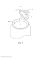
[018] A Figura 1 é uma vista em perspectiva duma lata de bebida que ilustra uma modalidade do extremo de abertura completa da presente invenção, na qual o olhal encontra-se num estado prévio de seu acionamento;[018] Figure 1 is a perspective view of a beverage can that illustrates an embodiment of the full opening end of the present invention, in which the eye is in a prior state of its activation;
[019] A Figura 2 é uma vista em perspectiva da parte traseira da lata que mostra a linha pontilhada de ventilação quebrada e o olhal ligeiramente deslocado para formar uma abertura de ventilação;[019] Figure 2 is a perspective view of the rear of the can showing the broken vent dotted line and the eye slightly offset to form a vent opening;
[020] A Figura 3 é uma vista em perspectiva da lata de bebida da Figura 1 que mostra a posição completamente aberta;[020] Figure 3 is a perspective view of the beverage can of Figure 1 showing the fully open position;
[021] A Figura 4 é uma vista superior da lata da Figura 1, com o olhal mostrado como translúcido para ilustrar a linha pontilhada de ventilação;[021] Figure 4 is a top view of the can of Figure 1, with the eye shown as translucent to illustrate the dotted line of vent;
[022] A Figura 5 é uma vista em secção transversal do extremo que mostra seu reborde periférico na sua configuração antes da costura num corpo de lata;[022] Figure 5 is a cross-sectional view of the end showing its peripheral edge in its configuration before sewing into a can body;
[023] A FIGURA 6 é uma vista alargada duma parte da FIGURA 4;[023] FIGURE 6 is an enlarged view of a portion of FIGURE 4;
[024] A Figura 7 é uma vista superior dum punção para formar a linha pontilhada de ventilação mostrada nas Figuras 4 e 6;[024] Figure 7 is a top view of a punch to form the dotted line of ventilation shown in Figures 4 and 6;
[025] A FIGURA 8 é uma vista alargada duma parte do punção da FIGURA 7; e[025] FIGURE 8 is an enlarged view of a portion of the punch of FIGURE 7; and
[026] A Figura 9 é uma tabla que mostra a diferencia entre os desenhos da técnica anterior e a configuração reclamada.[026] Figure 9 is a table that shows the difference between the prior art drawings and the claimed configuration.
[027] Como é ilustrado nas Figuras 1 a 6, uma montagem 10 de lata inclui um corpo 12 de lata e um extremo 14. O corpo 12 e o extremo 14 unem-se por uma costura, de preferência uma costura dupla 16 convencional. De preferência, o corpo 12 é um corpo de lata de bebida de 12 onças ou 350 ml estirado e embutido 12 convencional que forma-se a partir duma só peça de alumínio. Modalidades alternativas podem ter corpos de deferentes tamanhos, por exemplo, 473 ml (16 onças), 591 ml (20 onças), e 946 ml (32 onças) e os equivalentes de volume métrico. Os extremos 14 de lata podem ser do tipo que tipicamente são produzidos em quantidades comerciais. A invenção resume que os extremos 14 de lata provavelmente podem se produzir numa prensa de bainha que opera mais de 300 golpes por minuto.[027] As illustrated in Figures 1 to 6, a
[028] Em seu estado sem costuras mostrado na Figura 5, o extremo 14 inclui um reborde 23 periférico, uma parede 20, um orifício 22 escareado, e um painel 24 central. Como melhor é mostrado nas Figuras 1-4, em seu estado com costuras, o reborde periférico tem sido manipulado para formar uma parte da costura 16. O extremo de periferia é dum tamanho de 200, 202, 204, ou 206, embora a presente invenção compreende qualquer tamanho de extremo. A presente invenção também compreende qualquer configuração de paredes 20 e orifícios 22 escareados. As configurações de parede podem incluir paredes B64 convencionais, incluídas paredes de mandril, paredes de matriz dobrado, paredes de mandril de varias partes, paredes de mandril com características tais como aparadores, degraus, dobras, etc., e similares. Configurações de escareado podem incluir orifícios escareados com paredes laterais retas, paredes laterais dobradas, cordões estreitos, cordões amplos, cordões dobrados ou perfurados, e similares. As configurações dos extremos, paredes e orifícios escareados contemplados pela presente invenção incluem aqueles comercializados ou descritos pela Crown Cork & Seal Co., Ball Copr, Metal Container Corp. Container Development Ltd., Rexan Ltd, e Can Pack.[028] In its seamless state shown in Figure 5,
[029] Além disso, a presente invenção ilustra-se num extremo de lata de bebida que de preferência forma-se a partir duma liga metálica de alumínio serie 5000. Em concreto, a liga metálica de alumínio seria 5000 usada para a fabricação do extremo de lata tem uma resistência de limite elástico na tração de 39-55 ksi. Esta resistência de limite elástico na tração é adequadamente elevada para a pressão interna dada da lata por causa do seu diâmetro padrão. Este margem de resistência de limite elástico na tração também é relacionado com uma tendência relativamente maior a quebrar no extremo das linhas pontilhadas em relação aos metais mais brandos. A presente invenção não é limitada nesta liga metálica em particular, mas abrange aço, tais como uma placa de estanho, outros graus de alumínio, e similares, a menos que sejam estabelecidas nas reivindicações.[029] Furthermore, the present invention is illustrated in a beverage can end that is preferably formed from a 5000 series aluminum metal alloy. In particular, the 5000 aluminum metal alloy would be used for the manufacture of the end. of tin has an elastic limit strength in tensile of 39-55 ksi. This tensile yield strength is suitably high for the given internal pressure of the can because of its standard diameter. This elastic limit strength in tensile strength is also related to a relatively greater tendency to break at the extreme of the dotted lines relative to softer metals. The present invention is not limited to this particular metal alloy, but encompasses steel such as tin plate, other grades of aluminum, and the like, unless stated in the claims.
[030] O painel 24 central do extremo 14 de lata é circular e tem uma periferia 25 adjacente ao cordão 22. O extremo 14 de lata além disso inclui uma primeira linha pontilhada 25 disposta perto da periferia 25 do painel central. A primeira linha pontilhada 26 é continua para formar um painel 34 retirável. Um olhal 32, que inclui uma ponta 31, é fixada no painel 34 retirável do painel 24 central pelo rebite 30, de maneira que a ponta 31 seja disposta perto da primeira linha pontilhada 26. Um botão 29 é formado no painel 24 central ao redor do rebite 30 quando o olhal 32 é rebitado ao painel 24 central. O botão 29 é definido pela parte embutida do painel 24 central que forma-se durante o processo de rebitado.[030] The
[031] Para ajudar na descrição do painel 24 central, a linha PL de eixo de referência primário ou central define-se como estendendo-se através do centro do rebite 30 e através da linha central longitudinal do olhal 32 (Figura 4). O olhal 32 estende-se ao longo da linha PL. Para a grande maioria dos olhais comerciais, e como se mostra nas Figuras, a linha PL de referência primária estendera-se através do ponto de contato inicial entre a ponta do olhal 32 e seu ponto de contato no painel central. O eixo de referência transversal ou linha TL define-se estendendo-se através do centro do rebite 30 e em perpendicular na linha PL de referência primária. o plano definido pelas linhas PL e TL é paralelo ao plano definido pela parte superior da costura e paralelo ao painel 24 central, até o grau no qual o painel 24 central defina um plano em seu estado com costuras ou sem costuras. A linha TL de referência transversal divide o extremo 14 de lata numa parte frontal no lado da ponta do olhal e uma parte posterior no lado do talão de olhal.[031] To aid in the description of the
[032] A linha pontilhada 40 de ventilação inclui uma parte 42 central que entrecruza alinha PL, um par de ranhuras 45a e 45b de comprovação (Figura 6) dispostas em qualquer lado da linha PL ao redor da parte 42 central, um par de partes 46a e 46b laterais que estendem-se desde as ranhuras 45a e 45b de comprovação, cada uma das partes 46a e 46b laterais incluem um segmento 47a, 47b que é aproximadamente paralelo ao eixo lateral e um par de partes 50a e 50b laterais que estendem-se desde as partes 46a e 46b laterais, respectivamente, afastadas da linha TL.[032] The vent dotted
[033] Como é melhor mostrado na Figura 4, a parte 42 central da linha pontilhada de ventilação tem um segmento redondo que estende-se ao redor do rebite 30 (onde PL e TL, entrecruzam) separado do botão 29. A parte 42 central pode se definir pelo menos parcialmente por um radio de 3.556 mm (0.140 polegadas) ou alternativamente um radio de pelo menos 3.556 mm (0.140 polegadas), que estende-se desde o centro do rebite 30. De forma alternativa, a parte 42 central pode se definir pelo menos parcialmente por um radio na margem de 3.6528 - 3.81 mm (0.132-0.150 polegadas) por exemplo, a parte 42 central pode se definir pelo menos parcialmente por um radio de 0.132, 0.133, 0.134, 0.135, 0.136, 0.137, 0.138, 0.139, 0.140, 0.141, 0.142, 0.143, 0.144, 0.145, 0.146, 0.147, 0.148, 0.149, 0.150, ou um margem de rádios abrangidos por pelo menos dois dos rádios indicados na presente. A parte 42 central estende-se desde um ponto de interseção com PL para adiante enquanto estende-se ao redor do rebite 30 a aproximadamente as 3 em ponto e as 9 em ponto. A dimensão radial pode ser escolhida de acordo com parâmetros conhecidos, tais como a espessura do painel central, a espessura da linha pontilhada, a espessura da ranhura de comprovação, a seleção de material e parâmetros similares com base na descrição nesta especificação.[033] As best shown in Figure 4, the
[034] Na modalidade mostrada nas figuras, as ranhuras 45a, 45b de comprovação estendem-se desde a parte 42 central e têm um entalhe que é pouco mais profundo do que a parte central de maneira que o metal na área das ranhuras 45a, 45b de comprovação é mais grossa em relação ao metal na parte 42 central. Cada uma das ranhuras 45a, 45b de comprovação cede diante os extremos interiores correspondentes das partes 46a e 46b laterais através das transições 44a e 44b. As partes 46a e 46b laterais estendem-se geralmente de maneira lateral (é dizer, geralmente em paralelo na linha de referência transversal TL) e para fora em relação com o rebite 30. As partes 50a e 50b laterais estendem-se de maneira geral para trás desde os extremos exteriores das partes 46a e 46b laterais através das transições 48a e 48b. As partes 50a e 50b laterais terminam nas terminações 52 e 52b. As terminações da linha pontilhada de ventilação podem ser dobradas, rebordeadas ou anguladas em relação as partes laterais da linha pontilhada de ventilação, ou simplesmente podem ser os extremos das paredes laterais retas, como se mostra nas figuras.[034] In the embodiment shown in the figures, the
[035] Em outras modalidades, a linha pontilhada 40 de ventilação não tem ranhuras de comprovação. Mesmo que a linha pontilhada 40 de ventilação tem dimensões similares as modalidades com as ranhuras de comprovação, quando não use-se nenhuma ranhura de comprovação, a parte 42 central estende-se diretamente para as transições 44a e 44b. As partes 46a e 46b laterais estendem-se desde as transições 44a e 44b através das transições 48a e 48b. As partes 50a e 50b laterais terminam nas terminações 52a e 52b.[035] In other embodiments, the vent dotted
[036] Como é mostrado na Figura 6, uma articulação 54 se forma no painel 34 retirável entre as terminações 52a e 52b das partes 50a e 50b laterais. Uma aleta 56 se define pela linha pontilhada 40 ventilação e a articulação 54. Uma parte frontal da aleta 56 se define pelas partes 50a e 50b laterais. Os lados da aleta 56 se definem pelas partes 50a e 50b laterais. A parte posterior da aleta 56 se forma (com menos especificação na sua ubicação) pela articulação 54.[036] As shown in Figure 6, a
[037] Informação dimensional da linha pontilhada 40 de ventilação é oferecida em relação com a vista alargada da ferramenta 80 para formar a linha pontilhada de ventilação na Figura 8. De preferência, uma parte da linha pontilhada 40 de ventilação estende-se para (ou aproximadamente) ou para adiante da linha de referência transversal TL com o objetivo de promover o movimento ou articulação do olhal e rebite. Por exemplo, as partes 46a e 46b laterais de preferência estendem- se para adiante da linha transversal Tl por uma dimensão D1. De preferência, D1 é positivo e entre 0 e 1.27 mm (0 e 0.050 polegadas) e de maior preferência entre 3.556 mm e 0.08128 mm (0.010 polegadas e 0.032 polegadas). Na modalidade mostrada nas figuras, D1 tem aproximadamente 0.053 mm (0.021 polegadas).[037] Dimensional information of the vent dotted
[038] As partes 50a e 50b laterais separam-se mutuamente e estendem-se para trás de maneira que a aleta 56 cria suficiente área para ventilação. A abertura de ventilação se mostra na Figura 2 como número de referência 41. Neste contexto, as partes 50a e 50b laterais de preferência estendem- se para trás da linha de referência transversal TL por uma distancia D2 que pode ter entre 0.381 e 10.16 mm (0.15 e 0.4 polegadas), e de maior preferência tem entre 5.08 e 7.62 mm (0.2 e 0.3 polegadas). Na modalidade mostrada nas figuras, D2 tem 5.5118 mm (0.217 polegadas). Os extremos das terminações 52a e 52b de partes laterais separam-se por uma distancia de entre 12.7 mm e 25.4 mm (0.5 polegadas e 1.0 polegadas) e de preferência entre 15.24 mm e 20.32 mm (0.6 e 0.8 polegadas). Na modalidade mostrada, a distância entre 52a e 52b é 18.9484 mm (0.746 polegadas).[038] The
[039] Os lados da linha pontilhada de ventilação podem ser dobrados ou retos, e orientados em qualquer angulo A, medido em relação com a linha de referência primaria PL. Por exemplo, A pode ser aproximadamente cero (é dizer, os lados da linha pontilhada de ventilação podem ser aproximadamente paralelos na linha de referência primaria PL) entre +/- 10 graus, entre +/- 20 graus, ou entre +/- 30 graus. Na modalidade mostrada nas figuras, o angulo A é de 5 graus. A parte 42 central e as partes 46a e 46b laterais podem ser formas distintas da que se mostra nas figuras.[039] The sides of the vent dotted line can be bent or straight, and oriented at any angle A, measured in relation to the primary reference line PL. For example, A may be approximately cero (that is, the sides of the dotted vent line may be approximately parallel to the primary reference line PL) between +/- 10 degrees, between +/- 20 degrees, or between +/- 30 degrees. In the modality shown in the figures, angle A is 5 degrees. The
[040] A linha pontilhada 40 de ventilação tem uma dimensão residual de linha pontilhada aproximadamente uniforme pelo menos através da parte 42 central de linha pontilhada, as partes 46a e 46b laterais e a parte frontal das partes 50a e 50b laterais da linha pontilhada. De preferência, a dimensão residual de linha pontilhada para a parte 42 central de linha pontilhada, as partes 46a e 46b laterais e a parte frontal das partes 50a e 50b laterais de linha pontilhada tem entre 0.0508 mm e 0.1143 mm (.0020 e .0045 polegadas). As ranhuras 45a e 45b de comprovação têm uma linha pontilhada residual que geralmente é maior do que a parte 42 central de linha pontilhada, as partes 46a e 46b laterais, e a parte frontal das partes 50a e 50b laterais de linha pontilhada. Em concreto, a linha pontilhada residual para as ranhuras de comprovação pode ser maior em aproximadamente 0.1016 mm (0.0040 polegadas) de maneira que o resíduo para a ranhura de comprovação tem entre 0.1524 mm e 0.2159 mm (0.0060 e 0.0085 polegadas). A bigorna contra a qual atua a ferramenta 80 opcionalmente tem um degrau para controlar a dimensão residual.[040] The vent dotted
[041] A presente invenção abrange qualquer forma de linha pontilhada de ventilação e qualquer forma de aleta como é amplamente estabelecido nas reivindicações. A forma y as dimensões proporcionadas anteriormente para a linha pontilhada de ventilação 40 e a aleta 56 são para ilustração somente e não estão intencionadas para ser limitantes. Cada dimensão proporcionada anteriormente é aproximada. Como vai se entender por aquelas pessoas familiarizadas com o desenho de extremos de lata, as dimensões proporcionadas nesta especificação podem se determinar por vários parâmetros para a aplicação particular, incluindo o material do extremo e da espessura, as especificações de pressão interna, as dimensões da aleta e a área, e similares.[041] The present invention encompasses any form of dotted line of ventilation and any form of flap as is broadly set out in the claims. The shape y dimensions provided above for the dotted
[042] Para descrever a operação de montagem 10 da lata e para ilustrar o método inventivo correspondente, em concreto faz-se referência as Figuras 1-3 e 6. Antes da abertura, a montagem 101 de lata tem uma pressão interna criada quando se cheia com uma bebida carbonatada, cerveja, ou similares. As linhas pontilhadas 26 e 40 estão intactas e o olhal 32 está na sua parte de descanso convencional aproximadamente plana contra o painel 24 central ou aproximadamente horizontal.[042] To describe the
[043] Para abrir a montagem 10 de lata, um usuário levanta o extremo de talão de olhal 32, que move a ponta de olhal para o painel 24 central enquanto flexiona o metal ao redor do rebite até que a parte 42 central de linha pontilhada se quebra, como se mostra na Figura 2. A invenção supõe que ao ter a parte central separada do botão 29 e/ou definida por um radio de pelo menos 3.556 mm (0.140 polegadas) proporciona uma área de ventilação mais grande antes no processo de abertura. Em concreto, os extremos de lata da técnica anterior têm um radio de 28.7274 mm (1.131 polegadas) e um pequeno ajuste deste radio de modo que a parte central se separa do botão 29 resulta num incremento da classificação de prova de ventilação em 0.562 kg/cm2 (8 psi). A invenção também supõe que a separação da parte central de metal embutido que forma o botão 29 permite uma ruptura mais lenta e mais controlada que se parte central fora colocada no botão 29.[043] To open the
[044] De preferência, uma parte da linha pontilhada 40 de ventilação se quebra antes que a parte da primeira linha pontilhada 26 quebre-se para lograr a ventilação. A propagação da linha pontilhada 40 de ventilação é restringida conforme as ranhuras 45a, 45b de comprovação quebram-se. O metal grosso nas áreas das ranhuras 45a, 45b de comprovação (se são usadas) fractura-se mais lento que o resto da linha pontilhada 40 de ventilação. A quebra da linha pontilhada 40 de ventilação então propaga-se através das partes 46a e 46b laterais e para atrás através das partes 50a e 50b laterais da linha pontilhada conforme a aleta 56 se move para arriba ao redor da articulação 54. Neste contexto, a pressão interna da lata atua na aleta 56 para produzir rapidamente uma área de abertura relativamente grande para a ventilação de lata. Depois, similar à abertura dos extremos de lata convencionais, o usuário continua acionando o olhal 32 até que a linha pontilhada 24 principal se quebra e o painel 34 retirável se separa para criar a abertura 60.[044] Preferably, a part of the dotted
[045] Com referência na Figura 9, a tabla mostrada representa a diferencia dramática entre os desenhos da técnica anterior (as duas linhas mais pretas) dos pedidos de Ramsey e Fields e a configuração reclamada (as duas linhas mais claras). O eixo x representa a pressão em kg/cm2 (psi) e o eixo y é o índice de passo (100% máximo). A classificação de prova de ventilação incrementada do extremo de lata descrita na presente proporciona uma maior funcionalidade sobre a técnica anterior em relação com as latas de refrescante.[045] Referring to Figure 9, the table shown represents the dramatic difference between the prior art drawings (the two blackest lines) of the Ramsey and Fields orders and the claimed configuration (the two lightest lines). The x-axis represents pressure in kg/cm2 (psi) and the y-axis is the step index (100% maximum). The can end enhanced venting test rating described herein provides greater functionality over the prior art over coolant cans.
[046] As modalidades mostradas nas figuras e descritas anteriormente ilustram aspetos da presente invenção. A presente invenção não é limitada as modalidades particulares mostradas nas figuras, mas abrange estruturas e métodos mais amplos que a descrição e somente limitam-se por as reivindicações. Por exemplo, a presente invenção abrange materiais, configuração de parede de mandril, estrutura de costura e processos, configuração de painel de desprendimento rearticulado, essa área não é mostrada nas figuras a menos que se limite nas reivindicações.[046] The modalities shown in the figures and described above illustrate aspects of the present invention. The present invention is not limited to the particular embodiments shown in the figures, but encompasses structures and methods broader than the description and is only limited by the claims. For example, the present invention encompasses materials, mandrel wall configuration, sewing structure and processes, re-hinged release panel configuration, this area is not shown in the figures unless limited in the claims.
Claims (18)
Applications Claiming Priority (1)
| Application Number | Priority Date | Filing Date | Title |
|---|---|---|---|
| US14/075,299 | 2013-11-08 |
Publications (1)
| Publication Number | Publication Date |
|---|---|
| BR112016010339B1 true BR112016010339B1 (en) | 2021-11-03 |
Family
ID=
Similar Documents
| Publication | Publication Date | Title |
|---|---|---|
| CA2802053C (en) | Flap score venting of can end | |
| US10556718B2 (en) | End closure with a ring pull actuated secondary vent | |
| CA2777915C (en) | Vented beverage can end | |
| JP6215946B2 (en) | Rotation tab | |
| US8939308B2 (en) | Full aperture beverage end | |
| US8567158B2 (en) | Container end closure with optional secondary vent opening | |
| CA2872448C (en) | Metallic end closure with tear panel having improved rigidity | |
| AU2014346528B2 (en) | Full aperture end | |
| CA2558651C (en) | Easy open can end and process of making | |
| BR112016010339B1 (en) | CAN END WITHOUT FULL OPENING SEAMS, FULL OPENING CAN SET AND CAN END WITHOUT SEAMLESSING | |
| BR112018000997B1 (en) | CONTAINER END CLOSURE WITH A PERIPHERAL CORRUGATION AND METHOD OF OPENING A CONTAINER WITH AN END CLOSURE |