BR112016009829B1 - ULTRASONIC DIAGNOSTIC IMAGING SYSTEM THAT CAPTURES A PLURALITY OF STANDARD VIEW PLANS OF THE HEART AND METHOD TO CAPTURE A PLURALITY OF STANDARD VIEW PLANS OF THE HEART - Google Patents
ULTRASONIC DIAGNOSTIC IMAGING SYSTEM THAT CAPTURES A PLURALITY OF STANDARD VIEW PLANS OF THE HEART AND METHOD TO CAPTURE A PLURALITY OF STANDARD VIEW PLANS OF THE HEART Download PDFInfo
- Publication number
- BR112016009829B1 BR112016009829B1 BR112016009829-3A BR112016009829A BR112016009829B1 BR 112016009829 B1 BR112016009829 B1 BR 112016009829B1 BR 112016009829 A BR112016009829 A BR 112016009829A BR 112016009829 B1 BR112016009829 B1 BR 112016009829B1
- Authority
- BR
- Brazil
- Prior art keywords
- planes
- heart
- image
- tracking
- image data
- Prior art date
Links
Images


Classifications
-
- A—HUMAN NECESSITIES
- A61—MEDICAL OR VETERINARY SCIENCE; HYGIENE
- A61B—DIAGNOSIS; SURGERY; IDENTIFICATION
- A61B8/00—Diagnosis using ultrasonic, sonic or infrasonic waves
- A61B8/52—Devices using data or image processing specially adapted for diagnosis using ultrasonic, sonic or infrasonic waves
- A61B8/5215—Devices using data or image processing specially adapted for diagnosis using ultrasonic, sonic or infrasonic waves involving processing of medical diagnostic data
- A61B8/523—Devices using data or image processing specially adapted for diagnosis using ultrasonic, sonic or infrasonic waves involving processing of medical diagnostic data for generating planar views from image data in a user selectable plane not corresponding to the acquisition plane
-
- A—HUMAN NECESSITIES
- A61—MEDICAL OR VETERINARY SCIENCE; HYGIENE
- A61B—DIAGNOSIS; SURGERY; IDENTIFICATION
- A61B8/00—Diagnosis using ultrasonic, sonic or infrasonic waves
- A61B8/08—Detecting organic movements or changes, e.g. tumours, cysts, swellings
- A61B8/0883—Detecting organic movements or changes, e.g. tumours, cysts, swellings for diagnosis of the heart
-
- A—HUMAN NECESSITIES
- A61—MEDICAL OR VETERINARY SCIENCE; HYGIENE
- A61B—DIAGNOSIS; SURGERY; IDENTIFICATION
- A61B5/00—Measuring for diagnostic purposes; Identification of persons
- A61B5/14—Devices for taking samples of blood ; Measuring characteristics of blood in vivo, e.g. gas concentration within the blood, pH-value of blood
-
- A—HUMAN NECESSITIES
- A61—MEDICAL OR VETERINARY SCIENCE; HYGIENE
- A61B—DIAGNOSIS; SURGERY; IDENTIFICATION
- A61B8/00—Diagnosis using ultrasonic, sonic or infrasonic waves
- A61B8/13—Tomography
- A61B8/14—Echo-tomography
- A61B8/145—Echo-tomography characterised by scanning multiple planes
-
- A—HUMAN NECESSITIES
- A61—MEDICAL OR VETERINARY SCIENCE; HYGIENE
- A61B—DIAGNOSIS; SURGERY; IDENTIFICATION
- A61B8/00—Diagnosis using ultrasonic, sonic or infrasonic waves
- A61B8/44—Constructional features of the ultrasonic, sonic or infrasonic diagnostic device
- A61B8/4483—Constructional features of the ultrasonic, sonic or infrasonic diagnostic device characterised by features of the ultrasound transducer
- A61B8/4494—Constructional features of the ultrasonic, sonic or infrasonic diagnostic device characterised by features of the ultrasound transducer characterised by the arrangement of the transducer elements
-
- A—HUMAN NECESSITIES
- A61—MEDICAL OR VETERINARY SCIENCE; HYGIENE
- A61B—DIAGNOSIS; SURGERY; IDENTIFICATION
- A61B8/00—Diagnosis using ultrasonic, sonic or infrasonic waves
- A61B8/46—Ultrasonic, sonic or infrasonic diagnostic devices with special arrangements for interfacing with the operator or the patient
- A61B8/461—Displaying means of special interest
- A61B8/463—Displaying means of special interest characterised by displaying multiple images or images and diagnostic data on one display
-
- A—HUMAN NECESSITIES
- A61—MEDICAL OR VETERINARY SCIENCE; HYGIENE
- A61B—DIAGNOSIS; SURGERY; IDENTIFICATION
- A61B8/00—Diagnosis using ultrasonic, sonic or infrasonic waves
- A61B8/48—Diagnostic techniques
- A61B8/483—Diagnostic techniques involving the acquisition of a 3D volume of data
-
- A—HUMAN NECESSITIES
- A61—MEDICAL OR VETERINARY SCIENCE; HYGIENE
- A61B—DIAGNOSIS; SURGERY; IDENTIFICATION
- A61B8/00—Diagnosis using ultrasonic, sonic or infrasonic waves
- A61B8/48—Diagnostic techniques
- A61B8/486—Diagnostic techniques involving arbitrary m-mode
-
- A—HUMAN NECESSITIES
- A61—MEDICAL OR VETERINARY SCIENCE; HYGIENE
- A61B—DIAGNOSIS; SURGERY; IDENTIFICATION
- A61B8/00—Diagnosis using ultrasonic, sonic or infrasonic waves
- A61B8/48—Diagnostic techniques
- A61B8/488—Diagnostic techniques involving Doppler signals
-
- A—HUMAN NECESSITIES
- A61—MEDICAL OR VETERINARY SCIENCE; HYGIENE
- A61B—DIAGNOSIS; SURGERY; IDENTIFICATION
- A61B8/00—Diagnosis using ultrasonic, sonic or infrasonic waves
- A61B8/52—Devices using data or image processing specially adapted for diagnosis using ultrasonic, sonic or infrasonic waves
- A61B8/5269—Devices using data or image processing specially adapted for diagnosis using ultrasonic, sonic or infrasonic waves involving detection or reduction of artifacts
- A61B8/5276—Devices using data or image processing specially adapted for diagnosis using ultrasonic, sonic or infrasonic waves involving detection or reduction of artifacts due to motion
-
- G—PHYSICS
- G01—MEASURING; TESTING
- G01S—RADIO DIRECTION-FINDING; RADIO NAVIGATION; DETERMINING DISTANCE OR VELOCITY BY USE OF RADIO WAVES; LOCATING OR PRESENCE-DETECTING BY USE OF THE REFLECTION OR RERADIATION OF RADIO WAVES; ANALOGOUS ARRANGEMENTS USING OTHER WAVES
- G01S15/00—Systems using the reflection or reradiation of acoustic waves, e.g. sonar systems
- G01S15/66—Sonar tracking systems
-
- G—PHYSICS
- G01—MEASURING; TESTING
- G01S—RADIO DIRECTION-FINDING; RADIO NAVIGATION; DETERMINING DISTANCE OR VELOCITY BY USE OF RADIO WAVES; LOCATING OR PRESENCE-DETECTING BY USE OF THE REFLECTION OR RERADIATION OF RADIO WAVES; ANALOGOUS ARRANGEMENTS USING OTHER WAVES
- G01S15/00—Systems using the reflection or reradiation of acoustic waves, e.g. sonar systems
- G01S15/88—Sonar systems specially adapted for specific applications
- G01S15/89—Sonar systems specially adapted for specific applications for mapping or imaging
- G01S15/8906—Short-range imaging systems; Acoustic microscope systems using pulse-echo techniques
- G01S15/8909—Short-range imaging systems; Acoustic microscope systems using pulse-echo techniques using a static transducer configuration
- G01S15/8915—Short-range imaging systems; Acoustic microscope systems using pulse-echo techniques using a static transducer configuration using a transducer array
- G01S15/8925—Short-range imaging systems; Acoustic microscope systems using pulse-echo techniques using a static transducer configuration using a transducer array the array being a two-dimensional transducer configuration, i.e. matrix or orthogonal linear arrays
-
- G—PHYSICS
- G01—MEASURING; TESTING
- G01S—RADIO DIRECTION-FINDING; RADIO NAVIGATION; DETERMINING DISTANCE OR VELOCITY BY USE OF RADIO WAVES; LOCATING OR PRESENCE-DETECTING BY USE OF THE REFLECTION OR RERADIATION OF RADIO WAVES; ANALOGOUS ARRANGEMENTS USING OTHER WAVES
- G01S15/00—Systems using the reflection or reradiation of acoustic waves, e.g. sonar systems
- G01S15/88—Sonar systems specially adapted for specific applications
- G01S15/89—Sonar systems specially adapted for specific applications for mapping or imaging
- G01S15/8906—Short-range imaging systems; Acoustic microscope systems using pulse-echo techniques
- G01S15/8993—Three dimensional imaging systems
-
- G—PHYSICS
- G01—MEASURING; TESTING
- G01S—RADIO DIRECTION-FINDING; RADIO NAVIGATION; DETERMINING DISTANCE OR VELOCITY BY USE OF RADIO WAVES; LOCATING OR PRESENCE-DETECTING BY USE OF THE REFLECTION OR RERADIATION OF RADIO WAVES; ANALOGOUS ARRANGEMENTS USING OTHER WAVES
- G01S7/00—Details of systems according to groups G01S13/00, G01S15/00, G01S17/00
- G01S7/52—Details of systems according to groups G01S13/00, G01S15/00, G01S17/00 of systems according to group G01S15/00
- G01S7/52017—Details of systems according to groups G01S13/00, G01S15/00, G01S17/00 of systems according to group G01S15/00 particularly adapted to short-range imaging
- G01S7/52053—Display arrangements
- G01S7/52057—Cathode ray tube displays
- G01S7/5206—Two-dimensional coordinated display of distance and direction; B-scan display
- G01S7/52063—Sector scan display
-
- G—PHYSICS
- G01—MEASURING; TESTING
- G01S—RADIO DIRECTION-FINDING; RADIO NAVIGATION; DETERMINING DISTANCE OR VELOCITY BY USE OF RADIO WAVES; LOCATING OR PRESENCE-DETECTING BY USE OF THE REFLECTION OR RERADIATION OF RADIO WAVES; ANALOGOUS ARRANGEMENTS USING OTHER WAVES
- G01S7/00—Details of systems according to groups G01S13/00, G01S15/00, G01S17/00
- G01S7/52—Details of systems according to groups G01S13/00, G01S15/00, G01S17/00 of systems according to group G01S15/00
- G01S7/52017—Details of systems according to groups G01S13/00, G01S15/00, G01S17/00 of systems according to group G01S15/00 particularly adapted to short-range imaging
- G01S7/52053—Display arrangements
- G01S7/52057—Cathode ray tube displays
- G01S7/52074—Composite displays, e.g. split-screen displays; Combination of multiple images or of images and alphanumeric tabular information
-
- G—PHYSICS
- G06—COMPUTING; CALCULATING OR COUNTING
- G06T—IMAGE DATA PROCESSING OR GENERATION, IN GENERAL
- G06T7/00—Image analysis
- G06T7/0002—Inspection of images, e.g. flaw detection
- G06T7/0012—Biomedical image inspection
-
- G—PHYSICS
- G06—COMPUTING; CALCULATING OR COUNTING
- G06T—IMAGE DATA PROCESSING OR GENERATION, IN GENERAL
- G06T7/00—Image analysis
- G06T7/10—Segmentation; Edge detection
- G06T7/11—Region-based segmentation
-
- G—PHYSICS
- G06—COMPUTING; CALCULATING OR COUNTING
- G06T—IMAGE DATA PROCESSING OR GENERATION, IN GENERAL
- G06T7/00—Image analysis
- G06T7/10—Segmentation; Edge detection
- G06T7/149—Segmentation; Edge detection involving deformable models, e.g. active contour models
-
- G—PHYSICS
- G06—COMPUTING; CALCULATING OR COUNTING
- G06T—IMAGE DATA PROCESSING OR GENERATION, IN GENERAL
- G06T7/00—Image analysis
- G06T7/20—Analysis of motion
-
- G—PHYSICS
- G06—COMPUTING; CALCULATING OR COUNTING
- G06T—IMAGE DATA PROCESSING OR GENERATION, IN GENERAL
- G06T7/00—Image analysis
- G06T7/20—Analysis of motion
- G06T7/246—Analysis of motion using feature-based methods, e.g. the tracking of corners or segments
-
- G—PHYSICS
- G06—COMPUTING; CALCULATING OR COUNTING
- G06T—IMAGE DATA PROCESSING OR GENERATION, IN GENERAL
- G06T7/00—Image analysis
- G06T7/20—Analysis of motion
- G06T7/246—Analysis of motion using feature-based methods, e.g. the tracking of corners or segments
- G06T7/251—Analysis of motion using feature-based methods, e.g. the tracking of corners or segments involving models
-
- G—PHYSICS
- G06—COMPUTING; CALCULATING OR COUNTING
- G06T—IMAGE DATA PROCESSING OR GENERATION, IN GENERAL
- G06T7/00—Image analysis
- G06T7/70—Determining position or orientation of objects or cameras
- G06T7/73—Determining position or orientation of objects or cameras using feature-based methods
- G06T7/75—Determining position or orientation of objects or cameras using feature-based methods involving models
-
- G—PHYSICS
- G06—COMPUTING; CALCULATING OR COUNTING
- G06T—IMAGE DATA PROCESSING OR GENERATION, IN GENERAL
- G06T2207/00—Indexing scheme for image analysis or image enhancement
- G06T2207/10—Image acquisition modality
- G06T2207/10016—Video; Image sequence
-
- G—PHYSICS
- G06—COMPUTING; CALCULATING OR COUNTING
- G06T—IMAGE DATA PROCESSING OR GENERATION, IN GENERAL
- G06T2207/00—Indexing scheme for image analysis or image enhancement
- G06T2207/10—Image acquisition modality
- G06T2207/10132—Ultrasound image
- G06T2207/10136—3D ultrasound image
-
- G—PHYSICS
- G06—COMPUTING; CALCULATING OR COUNTING
- G06T—IMAGE DATA PROCESSING OR GENERATION, IN GENERAL
- G06T2207/00—Indexing scheme for image analysis or image enhancement
- G06T2207/20—Special algorithmic details
- G06T2207/20112—Image segmentation details
- G06T2207/20128—Atlas-based segmentation
-
- G—PHYSICS
- G06—COMPUTING; CALCULATING OR COUNTING
- G06T—IMAGE DATA PROCESSING OR GENERATION, IN GENERAL
- G06T2207/00—Indexing scheme for image analysis or image enhancement
- G06T2207/30—Subject of image; Context of image processing
- G06T2207/30004—Biomedical image processing
- G06T2207/30048—Heart; Cardiac
Abstract
sistema de imageamento diagnóstico ultrassônico que captura uma pluralidade de planos de vista padrão do coração e método para capturar uma pluralidade de planos de vista padrão do coração. trata-se de um sistema e método de imageamento diagnóstico ultrassônico que permite a captura automática de planos de visão padrão do coração em tempo real, como as vistas ap4, ap3 e ap2. uma imagem 3d do coração é capturada e é processada em conjunto com um modelo de coração geométrico. o modelo de coração é encaixado no coração em sua pose capturada para segmentar os planos de imagem desejados a partir dos dados de imagem 3d. durante intervalos de captura de imagem sucessivos, os planos de imagem são rastreados através de dados de imagem sucessivos, como um sistema de múltiplos planos, para atualizar uma exibição das múltiplas imagens. as capturas de imagem sucessivas podem ser capturas de imagem de volume ou capturas em múltiplos planos, apenas dos planos de imagem rastreados durante cada intervalo de captura.ultrasonic diagnostic imaging system that captures a plurality of standard heart view planes and a method for capturing a plurality of heart standard view planes. it is an ultrasonic diagnostic imaging system and method that allows the automatic capture of standard view planes of the heart in real time, such as the ap4, ap3 and ap2 views. a 3d image of the heart is captured and processed in conjunction with a geometric heart model. the heart model snaps to the heart in its captured pose to segment the desired image planes from the 3d image data. during successive image capture intervals, image planes are tracked through successive image data, as a multi-plane system, to update a display of the multiple images. successive snapshots can be volume snapshots or multi-plane snapshots of just the image planes tracked during each capture interval.
Description
[001] Esta invenção refere-se a sistemas de imageamento ultrassônicos médicos e, em particular, a sistemas por ultrassom 3D para imageamento cardíaco.[001] This invention relates to medical ultrasonic imaging systems and, in particular, to 3D ultrasound systems for cardiac imaging.
[002] No imageamento cardíaco por ultrassom, existem várias vistas planas padrão do coração que, com frequência, precisam ser capturadas para fazer medições padronizadas ou diagnóstico do desempenho cardíaco. Três dessas vistas padrão são a vista apical de 2 câmaras, a vista apical de 3 câmaras e a vista apical de 2 câmaras, comumente referidas como as vistas AP4, AP3 e AP2. Como o nome sugere, essas vistas planas do coração são todas capturadas, segurando-se a sonda de ultrassom abaixo da caixa torácica esquerda, onde se verá o coração a partir de seu ápice. A vista apical de 4 câmaras visualiza todas as quatro câmaras do coração, os átrios esquerdo e direito e os ventrículos esquerdo e direito. Essa vista é preferencial quando um médico deseja calcular fração de ejeção, visualizar o ventrículo esquerdo ou verificar a função diastólica ou estenose mitral. A vista apical de 3 câmaras possibilita que o médico visualize a válvula aórtica e a raiz aórtica. Esta vista é preferencial para verificar a contratilidade das paredes antero-lateral e posterior do coração. Ao alinhar o feixe de Doppler com a via de saída ventricular esquerda, o médico é capaz de avaliar quantitativamente a severidade da estenose aórtica. A vista apical de 2 câmaras possibilita a visualização e avaliação das paredes anterior e inferior do ventrículo esquerdo.[002] In cardiac ultrasound imaging, there are several standard plan views of the heart that often need to be captured to make standardized measurements or diagnostics of cardiac performance. Three of these standard views are the 2-chamber apical view, the 3-chamber apical view, and the 2-chamber apical view, commonly referred to as the AP4, AP3, and AP2 views. As the name suggests, these flat views of the heart are all captured by holding the ultrasound probe below the left rib cage, where the heart will be seen from its apex. The 4-chamber apical view visualizes all four chambers of the heart, the left and right atria, and the left and right ventricles. This view is preferred when a clinician wants to calculate ejection fraction, visualize the left ventricle, or check diastolic function or mitral stenosis. The 3-chamber apical view allows the clinician to view the aortic valve and aortic root. This view is preferred for checking the contractility of the anterolateral and posterior walls of the heart. By aligning the Doppler beam with the left ventricular outflow tract, the physician is able to quantitatively assess the severity of aortic stenosis. The 2-chamber apical view allows visualization and evaluation of the anterior and inferior walls of the left ventricle.
[003] Existem técnicas familiares e bem compreendidas para manipular uma sonda de ultrassom bidimensional para capturar essas vistas planas padrão do coração. A vista em 4 câmaras é tomada geralmente como a primeira vista e uma referência para as outras. Para capturar uma vista apical de 4 câmaras, o médico segura a sonda contra o lado esquerdo do paciente com a sonda dirigida para o ápice do coração e para cima, em direção ao ombro esquerdo. O entalhe na lateral da sonda que permite que o médico mantenha uma orientação esquerda-direita desejada entre a anatomia do paciente e a imagem no visor do sistema de ultrassom, está posicionada como os ponteiros do relógio nos horários de 2 ou 3 horas. Quando o posicionamento é adequado, as quatro câmaras do coração são claramente exibidas com o ápice no topo da tela e as câmaras direitas no lado esquerdo da tela. O ventrículo direito não deve ser maior do que dois terços da largura do ventrículo esquerdo.[003] There are familiar and well-understood techniques for manipulating a two-dimensional ultrasound probe to capture these standard flat views of the heart. The 4-chamber view is generally taken as the first view and a reference for the others. To capture an apical 4-chamber view, the clinician holds the probe against the patient's left side with the probe directed toward the apex of the heart and up toward the left shoulder. The notch on the side of the probe that allows the clinician to maintain a desired left-right orientation between the patient's anatomy and the image on the ultrasound system display is positioned like the hands of the clock at the 2 or 3 o'clock times. When positioning is appropriate, the four chambers of the heart are clearly displayed with the apex at the top of the screen and the right chambers on the left side of the screen. The right ventricle should not be more than two-thirds the width of the left ventricle.
[004] A partir da vista em 4 câmaras, a captura da vista apical de 3 câmaras requer apenas uma simples manipulação da sonda. A sonda é girada no sentido anti-horário contra o paciente, até o entalhe na sonda estar aproximadamente na posição correspondente a 11 horas. A vista em 3 câmaras deve ser vista agora na tela. Essa rotação significa que existe aproximadamente uma relação a 90° entre os planos das imagens das vistas em 4 e em 3 câmaras. Para capturar a vista em 2 câmaras, a sonda é adicionalmente girada até aproximadamente a posição correspondente a 9 horas. A vista apical em 2 câmaras deve estar exibida agora na tela. Isso significa que a vista em 2 câmaras está situada a uma rotação de aproximadamente 135° a partir da vista de 4 câmaras de referência.[004] From the 4-chamber view, capturing the 3-chamber apical view requires only simple probe manipulation. The probe is rotated counterclockwise against the patient until the notch on the probe is approximately at the 11 o'clock position. The 3-chamber view should now be seen on the screen. This rotation means that there is approximately a 90° relationship between the image planes of the 4 and 3 camera views. To capture the 2-camera view, the probe is additionally rotated to approximately the 9 o'clock position. The 2-chamber apical view should now be displayed on the screen. This means that the 2-camera view is situated at approximately 135° rotation from the reference 4-chamber view.
[005] Conforme pode ser apreendido do que foi anteriormente mencionado, um médico pode gastar uma quantidade de tempo considerável para capturar essas vistas e manipular a sonda de uma vista para outra. Seria desejável poder capturar essas vistas padrão do coração sem a cuidadosa e árdua manipulação da sonda descrita acima. Seria adicionalmente desejável que as vistas fossem capturadas automaticamente pelo sistema de ultrassom, sem qualquer manipulação especial da sonda.[005] As can be gleaned from the above, a physician may spend a considerable amount of time capturing these views and manipulating the probe from one view to another. It would be desirable to be able to capture these standard views of the heart without the careful and arduous manipulation of the probe described above. It would additionally be desirable for the views to be captured automatically by the ultrasound system, without any special manipulation of the probe.
[006] De acordo com os princípios da presente invenção, descreve-se um sistema e método de imageamento por ultrassom que permite a captura tridimensional do coração a partir de uma posição apical. Tendo a maior parte do volume do coração capturada em 3D, o sistema de ultrassom aplica um modelo matemático do coração ao volume 3D para identificar e segmentar três planos de visão apicais do coração, um plano de imagem AP4, um AP3 e um AP2. Uma vez segmentadas, os três planos de imagem são então operados como um sistema de três planos para rastrear o sistema de três planos em capturas subsequentes do volume 3D como uma transformação rígida. Dessa forma, o sistema de três planos pode ser visualizado em tempo real, seja pela extração de fatias de MPR (multiplanar reconstruction - reconstrução multiplanar) de imagens de volume ao vivo ou por varredura apenas dos três planos com uma sonda transdutora de arranjo de matriz.[006] According to the principles of the present invention, an ultrasound imaging system and method is described that allows the three-dimensional capture of the heart from an apical position. Having most of the heart volume captured in 3D, the ultrasound system applies a mathematical model of the heart to the 3D volume to identify and segment three apical view planes of the heart, an AP4, an AP3 and an AP2 imaging plane. Once segmented, the three image planes are then operated as a three-plane system to track the three-plane system in subsequent captures of the 3D volume as a rigid transformation. In this way, the three-plane system can be visualized in real time, either by extracting MPR (multiplanar reconstruction) slices from live volume images or by scanning only the three planes with an array array transducer probe. .
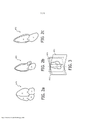
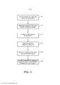
[007] Nos desenhos: a Figura 1 ilustra, em forma de diagrama de blocos, um sistema de ultrassom médico construído de acordo com os princípios da presente invenção. as Figuras 2a, 2b e 2c são ilustrações gráficas de vistas AP4, AP3 e AP2 do coração. a Figura 3 ilustra as orientações relativas dos planos das vistas AP4, AP3 e AP2, quando dispostas em um sistema de três planos. a Figura 4 é um fluxograma da captura, segmentação e rastreamento de um sistema de imagens apical em três planos, de acordo com os princípios da presente invenção. as Figuras 5a, 5b e 5c ilustram três imagens por ultrassom de um sistema apical de três planos, como aparecem visualizadas simultaneamente como imagens ao vivo em uma tela de exibição de ultrassom e quando sobrepostas pelos gráficos que representam os planos de visão de um modelo de coração.[007] In the drawings: Figure 1 illustrates, in block diagram form, a medical ultrasound system built according to the principles of the present invention. Figures 2a, 2b and 2c are graphic illustrations of AP4, AP3 and AP2 views of the heart. Figure 3 illustrates the relative orientations of the AP4, AP3, and AP2 view planes when arranged in a three-plane system. Figure 4 is a flowchart of capturing, segmenting and tracking a three-plane apical imaging system, in accordance with the principles of the present invention. Figures 5a, 5b and 5c illustrate three ultrasound images of a three-plane apical system as they appear viewed simultaneously as live images on an ultrasound display screen and when superimposed by graphics representing the planes of view of a model of heart.
[008] Com referência primeiramente à Figura 1, é mostrado um sistema de imageamento por ultrassom da presente invenção em forma de diagrama de blocos. O sistema de ultrassom é configurado por dois subsistemas, um subsistema de captura de extremidade frontal 10A e um subsistema de exibição 10B. Uma sonda de ultrassom é acoplada ao subsistema de captura que inclui um transdutor de matriz bidimensional 70 e um formador de microfeixe 72. O formador de microfeixe contém conjunto de circuitos que controlam os sinais aplicados a grupos de elementos (“emplastros”) do transdutor de matriz 70, e executam certo processamento dos sinais de eco recebidos pelos elementos de cada grupo. A formação de microfeixe na sonda reduz vantajosamente o número de condutores no cabo entre a sonda e o sistema de ultrassom e é descrita na patente US. 5.997.479 (Savord et al.) e na patente US. 6.,436.,048 (Pesque).[008] Referring primarily to Figure 1, an ultrasound imaging system of the present invention is shown in block diagram form. The ultrasound system is configured by two subsystems, a 10A front end capture subsystem and a 10B display subsystem. An ultrasound probe is coupled to the capture subsystem that includes a two-
[009] A sonda é acoplada ao subsistema de captura 10A do sistema de ultrassom. O subsistema de captura inclui um controlador de formação de feixe 74 que responde a um controle do usuário 36, e fornece sinais de controle ao formador de microfeixe 72, instruindo a sonda quanto à temporização, à frequência, à direção e à focalização de feixes de transmissão. O controlador de formação de feixe também controla a formação de feixe de sinais de eco recebidos pelo subsistema de captura por meio de seu controle de conversores de sinal analógico-para-digital (A/D) 18 e um sistema formador de feixe 20. Os sinais de eco recebidos pela sonda são amplificados pelo pré-amplificador e o conjunto de circuitos TGC (controle de ganho no tempo - time gain control) 16 no subsistema de captura, sendo então digitalizados pelos conversores A/D 18. Os sinais de eco digitalizados são então formados em feixes totalmente dirigidos e focalizados pelo sistema formador de feixe 20. Os sinais de eco são então processados por um processador de sinal 22, que faz filtragem digital, detecção de modo B e modo M e processamento Doppler, e pode fazer também outro processamento de sinal, como separação harmônica, redução de manchas e outro processamento de sinal de imagem desejado.[009] The probe is coupled to the 10A capture subsystem of the ultrasound system. The capture subsystem includes a
[010] Os sinais de eco produzidos pelo subsistema de captura 10A são acoplados ao subsistema de exibição 10B, que processa os sinais de eco para exibição no formato de imagem desejado. Os sinais de eco são processados por um processador de linha de imagem 24, que é capaz de fazer amostragem dos sinais de eco, emendar segmentos de feixes em sinais de linha completos e calcular a média dos sinais de linha para aprimoramento da relação sinal/ruído ou da persistência de fluxo. As imagens de linha de uma imagem 2D são convertidas por varredura para o formato de imagem desejado por um conversor de varredura 26 que faz a conversão “R-Teta”, como é conhecida na técnica. A imagem é, então, armazenada em um buffer ou em uma memória de imagens 28, a partir de onde ela pode ser exibida em uma tela 38. A imagem na memória 28 também é sobreposta por gráficos a serem exibidos com a imagem, os quais são gerados por um gerador de gráficos (não mostrado) que responde ao controle do usuário 36. Imagens individuais ou sequências de imagens podem ser armazenadas em uma memória (não mostrada) durante a captura de ciclos ou sequências de imagens.[010] The echo signals produced by the
[011] Para imageamento volumétrico em tempo real, o subsistema de exibição 10B inclui também um processador de renderização de imagem 3D 32 que recebe linhas de imagem do processador de linha de imagem 24 para a renderização das imagens tridimensionais em tempo real. As imagens 3D podem ser exibidas como imagens 3D ao vivo (tempo real) no visor 38 ou acopladas à memória de imagem 28 para armazenamento dos conjuntos de dados 3D para posterior revisão e diagnóstico.[011] For real-time volumetric imaging, the
[012] De acordo com os princípios da presente invenção, o subsistema de exibição inclui também um modelo de coração geométrico analítico armazenado na memória 40. Os dados do modelo de coração armazenados na memória são, conceitualmente, uma malha da superfície 3D que delineia os formatos de características principais do coração, como câmaras de fluido, válvulas cardíacas e similares. Em uma modalidade construída, a malha é composta de elementos triangulares interconectados, embora outras malhas também possam ser usadas, como malhas de elemento retangular ou quadrado ou malhas constituídas de curvas b-splines racionais não uniformes. Conforme contemplado aqui, o modelo cardíaco pode ser um modelo geométrico completamente detalhado ou simplesmente um modelo de marcações anatômicas, como paredes de câmara, ápice do coração, válvulas cardíacas ou contornos do plano da válvula, e similares. Também pode ser usado um modelo cardíaco que combine ambos. Um modelo cardíaco que identifique as marcações chave de planos padrão, pode ser usado para identificar aqueles planos padrão nos dados de imagem por ultrassom, por exemplo. A finalidade do modelo cardíaco é identificar ou segmentar uma imagem por ultrassom 3D do coração de um paciente. Essa função é desempenhada por um processador de rastreamento e segmentação de plano APn 42, que usa os dados do modelo cardíaco para extrair certos planos de imagem da imagem por ultrassom 3D, neste caso, planos de imagem AP2, AP3 e AP4. Esses planos de imagem são mostrados graficamente nas Figuras 2a, 2b e 2c. Um modelo de um plano AP4 de quatro câmaras do coração é mostrado na Figura 2a. Nessa vista, o médico pode ver todas as quatro câmaras do coração, o átrio direito e o ventrículo direito separados pela válvula tricúspide e o átrio esquerdo e o ventrículo esquerdo separados pela válvula mitral. O ápice do coração está na parte superior nessa orientação do modelo AP4. A Figura 2b ilustra um modelo de um plano de imagem de três câmaras AP3. A vista AP3 permite a visualização das câmaras do lado esquerdo do coração, assim como da raiz aórtica e da válvula aórtica. A Figura 2c ilustra um modelo AP2. Essa vista permite a visualização do átrio esquerdo, da válvula mitral e do ventrículo esquerdo. A Figura 3 é uma vista em perspectiva das orientações relativas destes três planos de visão, um em relação ao outro. Em um exame típico, o médico colocará a sonda de ultrassom abaixo do lado esquerdo da caixa torácica, direcionada para cima, em direção ao ombro direito. A sonda é manipulada até ser capturada a vista apical de 4 câmaras. Então, a sonda é inclinada para cima para capturar a via de saída LV e a válvula aórtica em uma vista apical de 3 câmaras A sonda é manipulada novamente sendo girada 90°, no sentido anti-horário, para capturar a vista de 2 câmaras. Deve-se observar que essa é uma tarefa meticulosa e demorada, que requer considerável habilidade por parte do médico. As vistas AP2, AP3 e AP4 são planos de vista padrão para muitos diagnósticos cardíacos.[012] In accordance with the principles of the present invention, the display subsystem also includes an analytical geometric heart model stored in
[013] Essa difícil tarefa e sua complexidade são remediadas por um sistema de ultrassom da presente invenção, por meio do qual os planos de visão apicais desejados são extraídos de uma imagem de ultrassom 3D e exibidos pelo uso analítico de um modelo de coração. Essa extração é feita pelo processador de segmentação e rastreamento de plano APn 42 que tem início ao encontrar a localização aproximada do modelo cardíaco no volume da imagem por ultrassom 3D. Um identificador de formato, implementado na forma de uma transformada de Hough, encontra a localização aproximada do modelo do coração na imagem 3D. Uma transformada afim localizada define melhor estruturas grandes como as câmaras de fluido do coração na imagem do volume. A sintonia fina localizada alinha mais precisamente o modelo com a anatomia no volume de imagem. Com o modelo de coração 3D agora alinhado com a estrutura anatômica do coração na imagem do volume, pontos de referência dos três planos apicais tirados do modelo de coração são usados para identificar os três planos na imagem de volume e os três planos de imagem, AP4, AP3 e AP2, são extraídos da imagem de volume.[013] This difficult task and its complexity are remedied by an ultrasound system of the present invention, whereby the desired apical view planes are extracted from a 3D ultrasound image and displayed by the analytical use of a heart model. This extraction is performed by the
[014] Em uma implementação desse processamento, o processador de rastreamento e segmentação de plano APn 42 opera em voxels da imagem de volume 3D do coração, da seguinte forma. O processador de rastreamento e segmentação de plano inclui um pré-processador que serve como um inicializador para um segmentador. O pré-processador analisa automaticamente completamente os dados de imagem e opera para classificar a visualização atual, ou seja, a visualização na qual a imagem do coração atual 3D foi capturada. Em outras palavras, o pré-processador tem capacidade para detectar a pose de um órgão a ser segmentado em relação a uma pose de referência. A “pose” é a posição do objeto e sua orientação em relação ao modelo, como uma orientação de referência. A pose detectada é expressa por “parâmetros de pose”. Os parâmetros descrevem uma transformação, ou seja, como um modelo geométrico do coração precisa ser deslocado e girado de modo que o modelo assim transformado corresponda à pose registrada na imagem. Com base nesses parâmetros de pose, os pontos do modelo geométrico do coração são, então, transformados para a pose estimada (“atual”). Em uma implementação preferencial, o modelo geométrico do coração é definido como uma malha de superfície 3D composta de elementos triangulares, sendo que a malha contorna aproximadamente um formato de coração padrão em uma dada pose de referência. O modelo assim transformado (ou seja, deslocado e girado) é fornecido então como um ponto de partida para a segmentação baseada no modelo do volume da imagem que se baseia no conhecimento prévio da posição e orientação do objeto a ser segmentado, nesse caso, a segmentação dos três planos de visão apicais.[014] In one implementation of this processing, the APn 42 plane tracking and segmentation processor operates on voxels of the 3D volume image of the heart, as follows. The plan segmentation and tracking processor includes a preprocessor that serves as an initiator for a segmenter. The preprocessor automatically completely analyzes the image data and operates to classify the current view, i.e. the view in which the current 3D heart image was captured. In other words, the preprocessor is able to detect the pose of an organ to be segmented in relation to a reference pose. The “pose” is the position of the object and its orientation relative to the model, as a reference orientation. The detected pose is expressed by “pose parameters”. The parameters describe a transformation, that is, how a geometric model of the heart needs to be shifted and rotated so that the model thus transformed corresponds to the pose recorded in the image. Based on these pose parameters, the points of the geometric model of the heart are then transformed to the estimated (“current”) pose. In a preferred implementation, the geometric model of the heart is defined as a 3D surface mesh composed of triangular elements, with the mesh approximately contouring a standard heart shape in a given reference pose. The model thus transformed (i.e. shifted and rotated) is then provided as a starting point for segmentation based on the image volume model which is based on prior knowledge of the position and orientation of the object to be segmented, in this case the segmentation of the three apical planes of vision.
[015] O pré-processador utiliza uma transformada de Hough generalizada (GHT - generalized Hough transform) com uma pluralidade de acumuladores, um para cada orientação do coração. Para lidar com uma faixa de possibilidades de pose do coração que variam bastante, orientações de pose frequentemente recorrentes são armazenadas no processador a partir das imagens 3D de treinamento e, após o agrupamento, um conjunto de transformações é calculado a partir dessas orientações. As transformações são então aplicadas na fase operacional durante o processo de votação GHT para preencher a pluralidade de acumuladores de Hough. Em seguida, busca-se na pluralidade de acumuladores de Hough pelo máximo de entradas de votação em todos os acumuladores de Hough para encontrar a pose instantânea do coração. Essa busca pode ser feita simultaneamente por todos os acumuladores de Hough, ou a busca pode ser feita sequencialmente. A entrada do acumulador Hough com a mais alta contagem é usada para representar a localização mais provável do objeto para uma dada orientação de pose β. Em uma implementação preferencial, a extração de pontos de referência dos dados de imagem é usada para determinar, a partir de uma pluralidade de transformações afins (ou outras), uma transformação ideal que melhor se relacione às estruturas na imagem instantânea. O pré- processador inclui uma porta de entrada para receber a imagem 3D e um classificador. Há também uma porta de saída para emitir os parâmetros de pose (β[=orientação], x[= posição]) da pose, conforme determinado pelo classificador. Essas informações de pose (β, x) podem ser aplicadas, então, ao modelo geométrico do coração. O modelo transformado forma o “modelo inicializado” para segmentação. Uma vez que a pose do coração na imagem a ser segmentada é conhecida (ou seja, o modelo inicializado está disponível), o segmentador aplica etapas de adaptação parametrizada e deformável ao modelo geométrico de coração. Dessa forma, o modelo é adaptado à estrutura do coração no volume de imagem instantâneo. Especificamente, as adaptações incluem um ou mais estágios em que as coordenadas do modelo são adaptadas aos dados de imagem de volume, aplicando-se sucessivamente uma transformação global rígida, global afim, multirrígida e deformável. Após se deformar o modelo inicializado, intensidades de valor de cinza ao longo das normais das faces triangulares do modelo de malha são avaliadas para definir os contornos da segmentação.[015] The preprocessor uses a generalized Hough transform (GHT - generalized Hough transform) with a plurality of accumulators, one for each orientation of the heart. To handle a range of widely varying heart pose possibilities, frequently recurring pose orientations are stored in the processor from the
[016] Quando se usa identificação de ponto de referência anatômico para registro do modelo de coração e extração do plano de imagem, um identificador de ponto de referência opera de modo a detectar/identificar um ou mais pontos de referência anatômicos na imagem do coração 3D. A detecção do ponto de referência na imagem pode ser baseada no algoritmo RANSAC (Random Sample Consensus - consenso de amostra aleatória), conforme descrito em “Random Sample Consensus ...", Communications of the ACM, volume 24(6), (1981) por M. Fischler et al. A coleção dos pontos de referência assim detectados pode então representar um esqueleto do modelo geométrico subjacente do coração quando supõe-se que esteja em uma determinada pose. O modelo de coração inclui pontos de referência-alvo que representam os pontos de referência nos mesmos. Nessa implementação, a operação do classificador é baseada em uma coleção de transformações Ti afins. As transformações Ti são aplicadas, uma a uma, aos pontos de referência detectados para efetuar uma transformação coordenada dos pontos de referência detectados. Os pontos de referência assim transformados podem então ser comparados com o modelo geométrico de referência. Em particular, os pontos de referência transformados na imagem são comparados com os pontos de referência-alvo do modelo de coração. Supõe-se que o modelo seja apresentado em relação à orientação de referência. Para cada transformação, as coordenadas dos pontos de referência transformados são então comparadas com as coordenadas dos pontos de referência-alvo do modelo. As coordenadas dos pontos de referência transformados de melhor correspondência (por exemplo, estão mais próximas a em relação a uma norma adequada) aos pontos de referência-alvo do modelo são então identificadas. A respectiva transformação que produz a melhor correspondência ou equivalência entre os pontos de referência transformados e os pontos de referência-alvo é então considerada como representativa da pose, conforme registrado na imagem de volume do coração. A “melhor” correspondência é estabelecida em relação a uma medição de similaridades. “Melhor” destina- se a incluir ser dentro de uma margem definida pelo usuário em vez de mais próxima no sentido aritmético embora uma implementação particular possa considerar, de fato, “melhor” como próximo a no sentido aritmético. O cálculo do que melhor corresponde em relação a uma margem predefinida permite processamento eficiente, porque o processador não precisa buscar todas as transformações predefinidas para avaliar a medida de similaridades. Assim que um valor de similaridade que esteja entre a margem é estabelecido, a unidade de saída retorna a transformação respectiva como a que “melhor corresponde”.[016] When using anatomical landmark identification for heart model registration and image plane extraction, a landmark identifier operates to detect/identify one or more anatomical landmarks in the 3D heart image . Reference point detection in the image can be based on the RANSAC (Random Sample Consensus) algorithm, as described in “Random Sample Consensus ...", Communications of the ACM, volume 24(6), (1981) ) by M. Fischler et al. The collection of landmarks thus detected can then represent a skeleton of the underlying geometric model of the heart when it is assumed to be in a certain pose. The heart model includes target landmarks that represent the reference points in them. In this implementation, the operation of the classifier is based on a collection of affine Ti transformations. The Ti transformations are applied, one by one, to the detected reference points to perform a coordinate transformation of the detected reference points. The thus transformed reference points can then be compared with the reference geometric model. In particular, the transformed reference points in the image are compared. the ones with the heart model target landmarks. The model is assumed to be presented relative to the reference orientation. For each transformation, the coordinates of the transformed reference points are then compared with the coordinates of the model's target reference points. The coordinates of the best matched transformed reference points (eg, are closest to a suitable norm) to the model's target reference points are then identified. The respective transformation that produces the best match or equivalence between the transformed landmarks and the target landmarks is then considered representative of the pose as recorded in the heart volume image. The “best” match is established against a similarity measurement. “Best” is intended to include being within a user-defined range rather than closer in the arithmetical sense although a particular implementation may actually regard “best” as being close to in the arithmetical sense. The calculation of what best matches against a predefined margin allows efficient processing, because the processor does not need to fetch all predefined transformations to evaluate the similarity measure. As soon as a similarity value that is between the margin is established, the output unit returns the respective transformation as the one that “best matches”.
[017] Pode-se pensar que cada uma das transformações afins predefinidas codifique uma determinada pose. Em particular, cada transformação afim inclui entre outros componentes (como cisalhamento) um componente de translação e rotação que descreve uma das respectivas poses. Uma descrição dos componentes de translação e rotação da transformação identificada de melhor correspondência é encaminhada ao segmentador para inicialização. Alternativamente, a transformação de melhor correspondência é diretamente aplicada ao modelo primeiramente, e é o modelo assim transformado que é então encaminhado para inicializar o segmentador. O segmentador desempenha a tarefa, agora direta, de identificar pontos de referência-alvo dos três planos apicais desejados e extrai, do volume de imagem, os três planos que contêm, mais completamente, aqueles pontos anatômicos.[017] It can be thought that each of the predefined affine transformations encodes a certain pose. In particular, each affine transformation includes among other components (such as shear) a translation and rotation component that describes one of the respective poses. A description of the translation and rotation components of the identified best match transformation is forwarded to the segmenter for initialization. Alternatively, the best match transformation is directly applied to the model first, and it is the model thus transformed that is then forwarded to initialize the segmenter. The segmenter performs the now straightforward task of identifying target reference points from the three desired apical planes and extracts from the image volume the three planes that most completely contain those anatomical points.
[018] Os três planos de visão apicais extraídos dos dados de imagem de coração 3D pelo processador de segmentação e rastreamento de plano APn 42, conforme descrito acima, são exibidos individualmente ou concorrentemente no visor de sistema de ultrassom 38, conforme ilustrado na Figura 5a (da vista de 4 câmaras), Figura 5b (da vista de 3 câmaras) e Figura 5c (da vista de 2 câmaras). Na implementação ilustrada, as câmaras e estruturas do coração de cada plano de imagem são segmentadas por um recobrimento de contornos anatômicos graficamente delineados 62, 64, 66, fornecidos pelo modelo cardíaco. Uma vez que isso tenha sido feito para uma imagem de volume, os planos APn podem ser rastreados através de sucessivos volumes de imagem, seja em tempo real ou no pós- processamento. Para rastreamento, os três planos não são tratados como planos de imagem não relacionados, mas como três planos de um sistema de três planos, conforme ilustrado na Figura 3. À medida que imagens sucessivas de volume do coração se tornam disponíveis, os três planos APn do modelo de coração são usados para extrair os três planos de imagem de cada imagem de volume sucessiva. Aqueles planos são rastreados no novo volume mediante análise do movimento dos pontos de referência a partir do sistema de três planos anterior ao sistema de três planos que acabou de ser identificado. Isso é feito por fluxo óptico ou registro de imagem, como por meio do uso de informação mútua, correspondência de bloco ou correspondência de característica, por exemplo. O movimento dos pontos de referência a partir de um plano ao próximo é usado para encontrar um vetor de movimento para cada plano, e os três vetores de movimento dos três planos são usados para determinar um vetor de movimento composto (transformação) do sistema de três planos. Em essência, os três vetores de movimento em plano são usados para identificar o movimento composto do sistema de três planos. Essa transformação é usada para modelar o movimento do sistema de três planos como uma transformação rígida em relação à sonda. A transformação rígida identifica a translação e a rotação do sistema de três planos de uma imagem de volume para a próxima e este deslocamento é usado para calcular a nova localização do sistema de três planos na nova imagem de volume. Como essa é uma transformação rígida, não há escalonamento ou deformação do modelo ou dados de imagem, o que facilita as demandas computacionais. Repete-se essa atualização do sistema de três planos e rastreamento para cada nova captura de imagem de volume. Ocasionalmente, para evitar movimento excessivo da sonda ou do coração, o processamento pode ser reinicializado, conforme descrito acima.[018] The three apical view planes extracted from the 3D heart image data by the APn 42 plane segmentation and tracking processor, as described above, are displayed individually or concurrently on the
[019] A Figura 4 ilustra uma sequência típica de segmentação e rastreamento de plano de referência, de acordo com os princípios da presente invenção. Na primeira etapa 50, uma imagem de volume 3D do coração é capturada por varredura apical. Como o coração é varrido de maneira apical, o processador de segmentação e rastreamento de plano APn 42 pode ser pré-condicionado a esperar encontrar o ápice do coração no topo da imagem de volume. Na etapa 52, o processador de rastreamento e segmentação de plano APn 42 segmenta os planos de visão AP4, AP3 e AP2 usando o modelo de coração para identificar a pose do coração e encaixar o modelo do coração nos dados de imagem 3D, conforme descrito acima. Na etapa 54, o processador usa as localizações de plano desejadas do modelo de coração para extrair e exibir as imagens de três planos. Na etapa 56, uma nova imagem de volume 3D é capturada, e na etapa 58, o sistema de três planos na nova imagem de volume é rastreada pela transformação rígida. Na etapa 60, as imagens do sistema de três planos rastreadas são extraídas dos novos dados de imagem e as imagens de três planos exibidas são atualizadas no visor.[019] Figure 4 illustrates a typical segmentation and reference plane tracking sequence, according to the principles of the present invention. In the
[020] Outras variações da invenção ocorrerão prontamente aos versados na técnica. Ao invés de extrair e exibir as vistas AP4, AP3 e AP2, outra vista pode, alternativa ou adicionalmente, ser capturada e exibida. O sistema de ultrassom pode ser usado para exibir as vistas AP4, AP5 e AP3, por exemplo, ou quatro planos de vista diferentes. Para velocidades de exibição de quadro mais altas, a informação de rastreamento pode ser usada para atualizar os planos de uma exibição em três planos que varre apenas os três planos de visão desejados e não um volume inteiro de cada vez. Por exemplo, após o coração modelo ter sido encaixado na anatomia do coração em uma imagem de volume, apenas os três planos podem ser varridos para a próxima atualização. Três planos de imagem que acabaram de ser varridos podem ser comparados com os três planos anteriores e os dados de movimento composto calculados (dados de rastreamento) usados para varrer os três planos nas localizações atualizadas de plano para exibição. Assim, os dados de rastreamento são usados para orientar a direção de varredura do plano da próxima captura de três planos por meio do controle do controlador de forma de feixe, conforme mostrado na Figura 1. Ao se varrer apenas três planos, ao invés de todo o volume do coração, melhora-se consideravelmente a taxa de quadros e a resolução espacial de exibição. Caso o movimento do coração ou da sonda se torne excessivo, o processo pode ser atualizado e reinicializado mediante a captura e processamento de uma nova imagem de volume, e a varredura em três planos é novamente iniciada. Como outra alternativa, os dados de imagem 3D podem ser transformados para ajuste do modelo de coração, ao invés do inverso para segmentação.[020] Other variations of the invention will readily occur to those skilled in the art. Instead of extracting and displaying views AP4, AP3 and AP2, another view can alternatively or additionally be captured and displayed. The ultrasound system can be used to display AP4, AP5 and AP3 views, for example, or four different view planes. For higher frame rates, the tracking information can be used to update the planes of a three-plane view that scans only the three desired view planes and not an entire volume at a time. For example, after the model heart has been fitted to the anatomy of the heart in a volume image, only the three planes can be scanned for the next update. Three image planes that have just been scanned can be compared to the previous three planes and the calculated composite motion data (tracking data) used to scan the three planes in the updated plane-to-display locations. Thus, the tracking data is used to guide the scan direction of the plane of the next three-plane capture through the beamform controller control, as shown in Figure 1. When scanning only three planes instead of the entire heart volume, the frame rate and spatial resolution of the display are greatly improved. If the movement of the heart or probe becomes excessive, the process can be updated and restarted by capturing and processing a new volume image, and the three-plane scan is started again. As another alternative, the 3D image data can be transformed to fit the heart model, rather than the reverse for segmentation.
Claims (15)
Applications Claiming Priority (3)
| Application Number | Priority Date | Filing Date | Title |
|---|---|---|---|
| US201361899895P | 2013-11-05 | 2013-11-05 | |
| US61/899,895 | 2013-11-05 | ||
| PCT/IB2014/065779 WO2015068099A1 (en) | 2013-11-05 | 2014-11-04 | Automated segmentation of tri-plane images for real time ultrasonic imaging |
Publications (2)
| Publication Number | Publication Date |
|---|---|
| BR112016009829A2 BR112016009829A2 (en) | 2017-08-01 |
| BR112016009829B1 true BR112016009829B1 (en) | 2022-02-22 |
Family
ID=51900925
Family Applications (1)
| Application Number | Title | Priority Date | Filing Date |
|---|---|---|---|
| BR112016009829-3A BR112016009829B1 (en) | 2013-11-05 | 2014-11-04 | ULTRASONIC DIAGNOSTIC IMAGING SYSTEM THAT CAPTURES A PLURALITY OF STANDARD VIEW PLANS OF THE HEART AND METHOD TO CAPTURE A PLURALITY OF STANDARD VIEW PLANS OF THE HEART |
Country Status (7)
| Country | Link |
|---|---|
| US (2) | US10123781B2 (en) |
| EP (1) | EP3066643B1 (en) |
| JP (2) | JP6441335B2 (en) |
| CN (1) | CN105900140B (en) |
| BR (1) | BR112016009829B1 (en) |
| RU (1) | RU2677055C2 (en) |
| WO (1) | WO2015068099A1 (en) |
Families Citing this family (21)
| Publication number | Priority date | Publication date | Assignee | Title |
|---|---|---|---|---|
| RU2677055C2 (en) * | 2013-11-05 | 2019-01-15 | Конинклейке Филипс Н.В. | Automated segmentation of tri-plane images for real time ultrasound imaging |
| KR102255831B1 (en) * | 2014-03-26 | 2021-05-25 | 삼성전자주식회사 | Method and ultrasound apparatus for recognizing an ultrasound image |
| KR101619802B1 (en) * | 2014-06-18 | 2016-05-11 | 기초과학연구원 | Method for generating cardiac left ventricular three dimensional image and apparatus thereof |
| EP2989988B1 (en) * | 2014-08-29 | 2017-10-04 | Samsung Medison Co., Ltd. | Ultrasound image display apparatus and method of displaying ultrasound image |
| WO2016156481A1 (en) * | 2015-03-31 | 2016-10-06 | Koninklijke Philips N.V. | Ultrasound imaging apparatus |
| US11413006B2 (en) * | 2016-04-26 | 2022-08-16 | Koninklijke Philips N.V. | 3D image compounding for ultrasound fetal imaging |
| US10362950B2 (en) | 2016-06-24 | 2019-07-30 | Analytics For Life Inc. | Non-invasive method and system for measuring myocardial ischemia, stenosis identification, localization and fractional flow reserve estimation |
| EP3516562A4 (en) * | 2016-09-21 | 2019-12-11 | Analytics For Life Inc. | Method and system for visualization of heart tissue at risk |
| DE102016117889B3 (en) * | 2016-09-22 | 2018-03-15 | Tomtec Imaging Systems Gmbh | Method and device for correcting dynamic models determined by tracking methods |
| JP7157074B2 (en) * | 2016-12-20 | 2022-10-19 | コーニンクレッカ フィリップス エヌ ヴェ | Navigation platform for medical devices, especially cardiac catheters |
| US11437149B2 (en) * | 2017-03-01 | 2022-09-06 | Koninklijke Philips N.V. | Echocardiogram context measurement tool |
| EP3381512A1 (en) | 2017-03-30 | 2018-10-03 | Koninklijke Philips N.V. | Determining at least one final two-dimensional image for visualizing an object of interest in a three-dimensional ultrasound volume |
| WO2018195874A1 (en) * | 2017-04-27 | 2018-11-01 | 深圳迈瑞生物医疗电子股份有限公司 | Ultrasonic detection method and ultrasonic imaging system for fetal heart |
| US10299764B2 (en) * | 2017-05-10 | 2019-05-28 | General Electric Company | Method and system for enhanced visualization of moving structures with cross-plane ultrasound images |
| JP7203823B2 (en) * | 2017-08-17 | 2023-01-13 | コーニンクレッカ フィリップス エヌ ヴェ | An ultrasound system that extracts image planes from volume data using touch interaction with the image |
| WO2019155037A1 (en) * | 2018-02-09 | 2019-08-15 | Koninklijke Philips N.V. | Multi-parametric tissue stiffness quantification |
| CN113610923A (en) * | 2018-07-26 | 2021-11-05 | 上海联影智能医疗科技有限公司 | Scanning positioning method and device, computer equipment and computer readable storage medium |
| EP3711673A1 (en) * | 2019-03-18 | 2020-09-23 | Koninklijke Philips N.V. | Methods and systems for adjusting the field of view of an ultrasound probe |
| US20230419602A1 (en) * | 2020-11-05 | 2023-12-28 | Koninklijke Philips N.V. | Rendering and displaying a 3d representation of an anatomical structure |
| US20220301240A1 (en) * | 2021-03-22 | 2022-09-22 | GE Precision Healthcare LLC | Automatic Model-Based Navigation System And Method For Ultrasound Images |
| US11922647B2 (en) * | 2021-09-08 | 2024-03-05 | Canon Medical Systems Corporation | Image rendering method and apparatus |
Family Cites Families (18)
| Publication number | Priority date | Publication date | Assignee | Title |
|---|---|---|---|---|
| US6106466A (en) * | 1997-04-24 | 2000-08-22 | University Of Washington | Automated delineation of heart contours from images using reconstruction-based modeling |
| US5997479A (en) | 1998-05-28 | 1999-12-07 | Hewlett-Packard Company | Phased array acoustic systems with intra-group processors |
| RU2173480C2 (en) * | 1999-11-03 | 2001-09-10 | Терпиловский Алексей Анатольевич | Method for creating virtual model of biologic object |
| US6468216B1 (en) | 2000-08-24 | 2002-10-22 | Kininklijke Philips Electronics N.V. | Ultrasonic diagnostic imaging of the coronary arteries |
| JP3802508B2 (en) * | 2003-04-21 | 2006-07-26 | アロカ株式会社 | Ultrasonic diagnostic equipment |
| US7555151B2 (en) * | 2004-09-02 | 2009-06-30 | Siemens Medical Solutions Usa, Inc. | System and method for tracking anatomical structures in three dimensional images |
| US7327872B2 (en) * | 2004-10-13 | 2008-02-05 | General Electric Company | Method and system for registering 3D models of anatomical regions with projection images of the same |
| JP5122743B2 (en) * | 2004-12-20 | 2013-01-16 | ゼネラル・エレクトリック・カンパニイ | System for aligning 3D images within an interventional system |
| CN101355904B (en) * | 2005-12-20 | 2012-01-11 | 皇家飞利浦电子股份有限公司 | Reconstruction unit for reconstructing a fine reproduction of at least a part of an object |
| CN101536001B (en) * | 2006-08-11 | 2014-09-10 | 皇家飞利浦电子股份有限公司 | Anatomy-related image-context-dependent applications for efficient diagnosis |
| US7889912B2 (en) * | 2006-09-15 | 2011-02-15 | The General Electric Company | Method for real-time tracking of cardiac structures in 3D echocardiography |
| US20110201935A1 (en) * | 2008-10-22 | 2011-08-18 | Koninklijke Philips Electronics N.V. | 3-d ultrasound imaging |
| US8265363B2 (en) * | 2009-02-04 | 2012-09-11 | General Electric Company | Method and apparatus for automatically identifying image views in a 3D dataset |
| US20100249589A1 (en) * | 2009-03-25 | 2010-09-30 | Peter Lysyansky | System and method for functional ultrasound imaging |
| GB201117804D0 (en) * | 2011-10-14 | 2011-11-30 | Siemens Medical Solutions | Automatic local contrast quantification tool |
| US9277970B2 (en) * | 2012-07-19 | 2016-03-08 | Siemens Aktiengesellschaft | System and method for patient specific planning and guidance of ablative procedures for cardiac arrhythmias |
| WO2014080319A1 (en) * | 2012-11-20 | 2014-05-30 | Koninklijke Philips N.V. | Automatic positioning of standard planes for real-time fetal heart evaluation |
| RU2677055C2 (en) * | 2013-11-05 | 2019-01-15 | Конинклейке Филипс Н.В. | Automated segmentation of tri-plane images for real time ultrasound imaging |
-
2014
- 2014-11-04 RU RU2016122066A patent/RU2677055C2/en active
- 2014-11-04 US US15/032,719 patent/US10123781B2/en active Active
- 2014-11-04 BR BR112016009829-3A patent/BR112016009829B1/en active IP Right Grant
- 2014-11-04 CN CN201480060603.9A patent/CN105900140B/en active Active
- 2014-11-04 EP EP14799216.8A patent/EP3066643B1/en active Active
- 2014-11-04 WO PCT/IB2014/065779 patent/WO2015068099A1/en active Application Filing
- 2014-11-04 JP JP2016526918A patent/JP6441335B2/en active Active
-
2018
- 2018-10-24 US US16/169,751 patent/US10799218B2/en active Active
- 2018-11-21 JP JP2018218117A patent/JP6745861B2/en active Active
Also Published As
| Publication number | Publication date |
|---|---|
| JP2019022824A (en) | 2019-02-14 |
| US10123781B2 (en) | 2018-11-13 |
| US20160249885A1 (en) | 2016-09-01 |
| JP2016534803A (en) | 2016-11-10 |
| US10799218B2 (en) | 2020-10-13 |
| WO2015068099A1 (en) | 2015-05-14 |
| RU2016122066A3 (en) | 2018-06-26 |
| RU2016122066A (en) | 2017-12-11 |
| BR112016009829A2 (en) | 2017-08-01 |
| JP6441335B2 (en) | 2018-12-19 |
| US20190059858A1 (en) | 2019-02-28 |
| JP6745861B2 (en) | 2020-08-26 |
| EP3066643A1 (en) | 2016-09-14 |
| EP3066643B1 (en) | 2020-05-27 |
| CN105900140A (en) | 2016-08-24 |
| CN105900140B (en) | 2019-02-05 |
| RU2677055C2 (en) | 2019-01-15 |
Similar Documents
| Publication | Publication Date | Title |
|---|---|---|
| US10799218B2 (en) | Automated segmentation of tri-plane images for real time ultrasonic imaging | |
| KR101908520B1 (en) | Landmark detection with spatial and temporal constraints in medical imaging | |
| US9179890B2 (en) | Model-based positioning for intracardiac echocardiography volume stitching | |
| US9155470B2 (en) | Method and system for model based fusion on pre-operative computed tomography and intra-operative fluoroscopy using transesophageal echocardiography | |
| US8073215B2 (en) | Automated detection of planes from three-dimensional echocardiographic data | |
| US9687204B2 (en) | Method and system for registration of ultrasound and physiological models to X-ray fluoroscopic images | |
| US10835207B2 (en) | Fast anatomical mapping using ultrasound images | |
| CN106340015B (en) | A kind of localization method and device of key point | |
| US8948484B2 (en) | Method and system for automatic view planning for cardiac magnetic resonance imaging acquisition | |
| KR20110128197A (en) | Automatic analysis of cardiac m-mode views | |
| CN107427279A (en) | Use the Ultrasonic Diagnosis of the cardiac function of the cardiac module chamber with user's control | |
| CN110956076B (en) | Method and system for structure identification in three-dimensional ultrasound data based on volume rendering | |
| US20110317897A1 (en) | Method and apparatus for automated localization of a moving structure | |
| Voigt et al. | Robust live tracking of mitral valve annulus for minimally-invasive intervention guidance | |
| JP6498316B2 (en) | Ultrasonic imaging apparatus and image processing method | |
| CN107427282A (en) | Ultrasonic Diagnosis to cardiac function is split by single-degree-of-freedom chamber | |
| US20220287686A1 (en) | System and method for real-time fusion of acoustic image with reference image | |
| CN112336378B (en) | M-type echocardiogram processing method and system for animal ultrasonic diagnosis | |
| JP2023125906A (en) | Neural network, and information processing apparatus and information processing method using the neural network | |
| JP2022111706A (en) | Image processing apparatus, image processing method, medical imaging apparatus, and program | |
| WO2020216752A1 (en) | System and method for two dimensional acoustic image compounding via deep learning | |
| Van Stralen et al. | A semi-automatic endocardial border detection method for 4D ultrasound data | |
| Liu et al. | Registration-based auto-detection of the optimal cross sections in 3D echocardiographic images | |
| Leung | Automated Analysis of 3D Stress Echocardiography | |
| BR112015004061B1 (en) | ULTRASOUND IMAGING SYSTEM FOR INSPECTION OF AN OBJECT IN A VOLUME, AND METHOD FOR PROVISION OF A THREE-DIMENSIONAL ULTRASOUND IMAGE OF AN OBJECT IN A VOLUME. |
Legal Events
| Date | Code | Title | Description |
|---|---|---|---|
| B06U | Preliminary requirement: requests with searches performed by other patent offices: procedure suspended [chapter 6.21 patent gazette] | ||
| B09A | Decision: intention to grant [chapter 9.1 patent gazette] | ||
| B16A | Patent or certificate of addition of invention granted [chapter 16.1 patent gazette] |
Free format text: PRAZO DE VALIDADE: 20 (VINTE) ANOS CONTADOS A PARTIR DE 04/11/2014, OBSERVADAS AS CONDICOES LEGAIS. |