BR112016005462B1 - TROCATER AND KIT TO USE IN A LAPAROSCOPIC PROCEDURE - Google Patents
TROCATER AND KIT TO USE IN A LAPAROSCOPIC PROCEDURE Download PDFInfo
- Publication number
- BR112016005462B1 BR112016005462B1 BR112016005462-8A BR112016005462A BR112016005462B1 BR 112016005462 B1 BR112016005462 B1 BR 112016005462B1 BR 112016005462 A BR112016005462 A BR 112016005462A BR 112016005462 B1 BR112016005462 B1 BR 112016005462B1
- Authority
- BR
- Brazil
- Prior art keywords
- trocar
- anchor
- models
- tissue
- cannula
- Prior art date
Links
Images


Classifications
-
- A—HUMAN NECESSITIES
- A61—MEDICAL OR VETERINARY SCIENCE; HYGIENE
- A61B—DIAGNOSIS; SURGERY; IDENTIFICATION
- A61B17/00—Surgical instruments, devices or methods, e.g. tourniquets
- A61B17/34—Trocars; Puncturing needles
- A61B17/3417—Details of tips or shafts, e.g. grooves, expandable, bendable; Multiple coaxial sliding cannulas, e.g. for dilating
- A61B17/3421—Cannulas
- A61B17/3423—Access ports, e.g. toroid shape introducers for instruments or hands
-
- A—HUMAN NECESSITIES
- A61—MEDICAL OR VETERINARY SCIENCE; HYGIENE
- A61B—DIAGNOSIS; SURGERY; IDENTIFICATION
- A61B17/00—Surgical instruments, devices or methods, e.g. tourniquets
- A61B17/0057—Implements for plugging an opening in the wall of a hollow or tubular organ, e.g. for sealing a vessel puncture or closing a cardiac septal defect
-
- A—HUMAN NECESSITIES
- A61—MEDICAL OR VETERINARY SCIENCE; HYGIENE
- A61B—DIAGNOSIS; SURGERY; IDENTIFICATION
- A61B17/00—Surgical instruments, devices or methods, e.g. tourniquets
- A61B17/02—Surgical instruments, devices or methods, e.g. tourniquets for holding wounds open; Tractors
- A61B17/0218—Surgical instruments, devices or methods, e.g. tourniquets for holding wounds open; Tractors for minimally invasive surgery
-
- A—HUMAN NECESSITIES
- A61—MEDICAL OR VETERINARY SCIENCE; HYGIENE
- A61B—DIAGNOSIS; SURGERY; IDENTIFICATION
- A61B17/00—Surgical instruments, devices or methods, e.g. tourniquets
- A61B17/04—Surgical instruments, devices or methods, e.g. tourniquets for suturing wounds; Holders or packages for needles or suture materials
- A61B17/0401—Suture anchors, buttons or pledgets, i.e. means for attaching sutures to bone, cartilage or soft tissue; Instruments for applying or removing suture anchors
-
- A—HUMAN NECESSITIES
- A61—MEDICAL OR VETERINARY SCIENCE; HYGIENE
- A61B—DIAGNOSIS; SURGERY; IDENTIFICATION
- A61B17/00—Surgical instruments, devices or methods, e.g. tourniquets
- A61B17/04—Surgical instruments, devices or methods, e.g. tourniquets for suturing wounds; Holders or packages for needles or suture materials
- A61B17/0469—Suturing instruments for use in minimally invasive surgery, e.g. endoscopic surgery
-
- A—HUMAN NECESSITIES
- A61—MEDICAL OR VETERINARY SCIENCE; HYGIENE
- A61B—DIAGNOSIS; SURGERY; IDENTIFICATION
- A61B17/00—Surgical instruments, devices or methods, e.g. tourniquets
- A61B17/04—Surgical instruments, devices or methods, e.g. tourniquets for suturing wounds; Holders or packages for needles or suture materials
- A61B17/0482—Needle or suture guides
-
- A—HUMAN NECESSITIES
- A61—MEDICAL OR VETERINARY SCIENCE; HYGIENE
- A61B—DIAGNOSIS; SURGERY; IDENTIFICATION
- A61B17/00—Surgical instruments, devices or methods, e.g. tourniquets
- A61B17/34—Trocars; Puncturing needles
- A61B17/3417—Details of tips or shafts, e.g. grooves, expandable, bendable; Multiple coaxial sliding cannulas, e.g. for dilating
- A61B17/3421—Cannulas
-
- A—HUMAN NECESSITIES
- A61—MEDICAL OR VETERINARY SCIENCE; HYGIENE
- A61B—DIAGNOSIS; SURGERY; IDENTIFICATION
- A61B17/00—Surgical instruments, devices or methods, e.g. tourniquets
- A61B17/34—Trocars; Puncturing needles
- A61B17/3468—Trocars; Puncturing needles for implanting or removing devices, e.g. prostheses, implants, seeds, wires
-
- A—HUMAN NECESSITIES
- A61—MEDICAL OR VETERINARY SCIENCE; HYGIENE
- A61B—DIAGNOSIS; SURGERY; IDENTIFICATION
- A61B17/00—Surgical instruments, devices or methods, e.g. tourniquets
- A61B17/34—Trocars; Puncturing needles
- A61B17/3478—Endoscopic needles, e.g. for infusion
-
- A—HUMAN NECESSITIES
- A61—MEDICAL OR VETERINARY SCIENCE; HYGIENE
- A61B—DIAGNOSIS; SURGERY; IDENTIFICATION
- A61B17/00—Surgical instruments, devices or methods, e.g. tourniquets
- A61B17/34—Trocars; Puncturing needles
- A61B17/3462—Trocars; Puncturing needles with means for changing the diameter or the orientation of the entrance port of the cannula, e.g. for use with different-sized instruments, reduction ports, adapter seals
-
- A—HUMAN NECESSITIES
- A61—MEDICAL OR VETERINARY SCIENCE; HYGIENE
- A61B—DIAGNOSIS; SURGERY; IDENTIFICATION
- A61B17/00—Surgical instruments, devices or methods, e.g. tourniquets
- A61B2017/00004—(bio)absorbable, (bio)resorbable, resorptive
-
- A—HUMAN NECESSITIES
- A61—MEDICAL OR VETERINARY SCIENCE; HYGIENE
- A61B—DIAGNOSIS; SURGERY; IDENTIFICATION
- A61B17/00—Surgical instruments, devices or methods, e.g. tourniquets
- A61B17/0057—Implements for plugging an opening in the wall of a hollow or tubular organ, e.g. for sealing a vessel puncture or closing a cardiac septal defect
- A61B2017/00637—Implements for plugging an opening in the wall of a hollow or tubular organ, e.g. for sealing a vessel puncture or closing a cardiac septal defect for sealing trocar wounds through abdominal wall
-
- A—HUMAN NECESSITIES
- A61—MEDICAL OR VETERINARY SCIENCE; HYGIENE
- A61B—DIAGNOSIS; SURGERY; IDENTIFICATION
- A61B17/00—Surgical instruments, devices or methods, e.g. tourniquets
- A61B17/0057—Implements for plugging an opening in the wall of a hollow or tubular organ, e.g. for sealing a vessel puncture or closing a cardiac septal defect
- A61B2017/00646—Type of implements
- A61B2017/00663—Type of implements the implement being a suture
-
- A—HUMAN NECESSITIES
- A61—MEDICAL OR VETERINARY SCIENCE; HYGIENE
- A61B—DIAGNOSIS; SURGERY; IDENTIFICATION
- A61B17/00—Surgical instruments, devices or methods, e.g. tourniquets
- A61B17/04—Surgical instruments, devices or methods, e.g. tourniquets for suturing wounds; Holders or packages for needles or suture materials
- A61B17/0401—Suture anchors, buttons or pledgets, i.e. means for attaching sutures to bone, cartilage or soft tissue; Instruments for applying or removing suture anchors
- A61B2017/0409—Instruments for applying suture anchors
-
- A—HUMAN NECESSITIES
- A61—MEDICAL OR VETERINARY SCIENCE; HYGIENE
- A61B—DIAGNOSIS; SURGERY; IDENTIFICATION
- A61B17/00—Surgical instruments, devices or methods, e.g. tourniquets
- A61B17/04—Surgical instruments, devices or methods, e.g. tourniquets for suturing wounds; Holders or packages for needles or suture materials
- A61B17/0401—Suture anchors, buttons or pledgets, i.e. means for attaching sutures to bone, cartilage or soft tissue; Instruments for applying or removing suture anchors
- A61B2017/0417—T-fasteners
-
- A—HUMAN NECESSITIES
- A61—MEDICAL OR VETERINARY SCIENCE; HYGIENE
- A61B—DIAGNOSIS; SURGERY; IDENTIFICATION
- A61B17/00—Surgical instruments, devices or methods, e.g. tourniquets
- A61B17/04—Surgical instruments, devices or methods, e.g. tourniquets for suturing wounds; Holders or packages for needles or suture materials
- A61B17/0401—Suture anchors, buttons or pledgets, i.e. means for attaching sutures to bone, cartilage or soft tissue; Instruments for applying or removing suture anchors
- A61B2017/0445—Suture anchors, buttons or pledgets, i.e. means for attaching sutures to bone, cartilage or soft tissue; Instruments for applying or removing suture anchors cannulated, e.g. with a longitudinal through-hole for passage of an instrument
-
- A—HUMAN NECESSITIES
- A61—MEDICAL OR VETERINARY SCIENCE; HYGIENE
- A61B—DIAGNOSIS; SURGERY; IDENTIFICATION
- A61B17/00—Surgical instruments, devices or methods, e.g. tourniquets
- A61B17/04—Surgical instruments, devices or methods, e.g. tourniquets for suturing wounds; Holders or packages for needles or suture materials
- A61B17/0401—Suture anchors, buttons or pledgets, i.e. means for attaching sutures to bone, cartilage or soft tissue; Instruments for applying or removing suture anchors
- A61B2017/0464—Suture anchors, buttons or pledgets, i.e. means for attaching sutures to bone, cartilage or soft tissue; Instruments for applying or removing suture anchors for soft tissue
-
- A—HUMAN NECESSITIES
- A61—MEDICAL OR VETERINARY SCIENCE; HYGIENE
- A61B—DIAGNOSIS; SURGERY; IDENTIFICATION
- A61B17/00—Surgical instruments, devices or methods, e.g. tourniquets
- A61B17/04—Surgical instruments, devices or methods, e.g. tourniquets for suturing wounds; Holders or packages for needles or suture materials
- A61B17/0469—Suturing instruments for use in minimally invasive surgery, e.g. endoscopic surgery
- A61B2017/047—Suturing instruments for use in minimally invasive surgery, e.g. endoscopic surgery having at least one proximally pointing needle located at the distal end of the instrument, e.g. for suturing trocar puncture wounds starting from inside the body
-
- A—HUMAN NECESSITIES
- A61—MEDICAL OR VETERINARY SCIENCE; HYGIENE
- A61B—DIAGNOSIS; SURGERY; IDENTIFICATION
- A61B17/00—Surgical instruments, devices or methods, e.g. tourniquets
- A61B17/04—Surgical instruments, devices or methods, e.g. tourniquets for suturing wounds; Holders or packages for needles or suture materials
- A61B17/0469—Suturing instruments for use in minimally invasive surgery, e.g. endoscopic surgery
- A61B2017/0472—Multiple-needled, e.g. double-needled, instruments
-
- A—HUMAN NECESSITIES
- A61—MEDICAL OR VETERINARY SCIENCE; HYGIENE
- A61B—DIAGNOSIS; SURGERY; IDENTIFICATION
- A61B17/00—Surgical instruments, devices or methods, e.g. tourniquets
- A61B17/34—Trocars; Puncturing needles
- A61B17/3417—Details of tips or shafts, e.g. grooves, expandable, bendable; Multiple coaxial sliding cannulas, e.g. for dilating
- A61B2017/3454—Details of tips
- A61B2017/346—Details of tips with wings
-
- A—HUMAN NECESSITIES
- A61—MEDICAL OR VETERINARY SCIENCE; HYGIENE
- A61B—DIAGNOSIS; SURGERY; IDENTIFICATION
- A61B17/00—Surgical instruments, devices or methods, e.g. tourniquets
- A61B17/34—Trocars; Puncturing needles
- A61B2017/348—Means for supporting the trocar against the body or retaining the trocar inside the body
- A61B2017/3482—Means for supporting the trocar against the body or retaining the trocar inside the body inside
- A61B2017/3484—Anchoring means, e.g. spreading-out umbrella-like structure
- A61B2017/3488—Fixation to inner organ or inner body tissue
Abstract
trocáter e kit para usar em um procedimento laparoscópico. trocáter adaptado para inserção através de uma camada facial de uma parede abdominal, que compreende uma extremidade proximal configurada para ser manuseada por um utilizador; uma extremidade distal configurada para inserção num tecido; e uma haste que se estende entre a extremidade proximal e a extremidade distal; em que a haste compreende uma parte estreita proximal à extremidade distal, em que a parte estreita define pelo menos um recesso formado e dimensionado para receber tecido fascial, terminando o recesso, numa extremidade distal, com uma superfície da haste virada geralmente proximalmente configurada diretamente por baixo da parte estreita, em que a superfície está virada proximalmente e a parte estreita está formada e dimensionada para estabilizar o trocáter na parede abdominal pela fáscia. em alguns modelos, é providenciado um conjunto de um trocáter e cânula externa. em alguns modelos, o trocáter e/ou conjunto de trocáter e cânula externa estão configurados para aplicação de uma ou mais âncoras e/ou suturas no tecido.trocar and kit for use in a laparoscopic procedure. trocar adapted for insertion through a facial layer of an abdominal wall, comprising a proximal end configured to be handled by a user; a distal end configured for insertion into tissue; and a rod extending between the proximal end and the distal end; wherein the rod comprises a narrow portion proximal to the distal end, wherein the narrow portion defines at least one recess formed and sized to receive fascial tissue, the recess terminating at a distal end with a generally proximally facing surface of the rod configured directly by below the narrow part, where the surface is proximally turned and the narrow part is formed and sized to stabilize the trochar in the abdominal wall by the fascia. in some models, an assembly of a trocar and external cannula is provided. in some models, the trocar and/or trocar and external cannula assembly are configured to apply one or more anchors and/or sutures to the tissue.
Description
[001] A presente invenção, em alguns seus modelos, refere-se a um trocáter, e, mais em particular, mas não exclusivamente, a um conjunto de trocáter e cânula externa para usar num procedimento laparoscópico.[001] The present invention, in some of its models, relates to a trocar, and more particularly, but not exclusively, to a trocar and external cannula assembly for use in a laparoscopic procedure.
[002] A cirurgia laparoscópica inclui normalmente a utilização de um trocáter para introduzir um laparoscópio ou outros instrumentos cirúrgicos através de uma porta incisada na parede abdominal. Segundo o procedimento, podem ser usadas várias técnicas para fechar feridas, com ou sem controlo visual. O fecho suficiente da porta é de extrema importância para prevenir complicações, tais como hérnia.[002] Laparoscopic surgery typically includes the use of a trocar to introduce a laparoscope or other surgical instruments through an incised port in the abdominal wall. Depending on the procedure, various techniques can be used to close wounds, with or without visual control. Sufficient door closure is of utmost importance to prevent complications such as hernia.
[003] As seguintes publicações apresentam um dispositivo trocáter para fechar feridas:[003] The following publications present a trocar device for wound closure:
[004] A publicação da patente europeia número EP0568098 A2 em Greenwald et al. discloses "Um dispositivo trocáter para fechar feridas (10) inclui um corpo alongado (12) com uma extremidade distal (20) para inserção através de uma ferida de punção com trocáter, uma extremidade proximal (14), e um primeiro (70) e um segundo (72) porta-agulhas retrátil disposto na extremidade distal (20) do corpo (12). Os porta-agulhas (70, 72) são movíveis entre uma posição retraída e uma posição estendida. Um atuador (32) disposto na extremidade proximal (14) do corpo (12) move os porta-agulhas (70,72) desde a posição retraída até à posição estendida, de modo a que os porta-agulhas (70,72) possam ser retraídos para permitir que o dispositivo (10) seja inserido através de uma ferida com trocáter preferencialmente através de uma cânula inserida na ferida, e estendidos para a posição das agulhas (56,58) adjacente à ferida, para permitir que a ferida seja suturada."[004] European patent publication number EP0568098 A2 in Greenwald et al. discloses "A trocar wound closure device (10) includes an elongate body (12) with a distal end (20) for insertion through a trocar puncture wound, a proximal end (14), and a first (70) and a second retractable needle holder (72) disposed at the distal end (20) of the body (12). The needle holders (70, 72) are movable between a retracted position and an extended position. An actuator (32) disposed at the end (14) of the body (12) moves the needle holders (70,72) from the retracted to the extended position so that the needle holders (70,72) can be retracted to allow the device ( 10) is inserted through a trocar wound preferably through a cannula inserted into the wound, and extended to the position of the needles (56,58) adjacent to the wound to allow the wound to be sutured."
[005] A patente norte-americana n.° 8.109.943 para Boraiah et al. apresenta “sistemas e métodos para suturar a implantação de âncora. Um sistema de acordo com a presente invenção é um sistema de trocáter que inclui um conjunto de cânula e um conjunto de obturador, em que o conjunto de cânula fornece um conjunto de agulhas e o conjunto de obturador fornece um mecanismo de atuação de agulhas. O conjunto de obturador pode ser, pelo menos parcialmente, inserido no conjunto de cânula e disposto para operativamente acoplar o mecanismo de atuação da agulha ao conjunto de agulha. O conjunto de agulha inclui pelo menos uma agulha, possuindo cada agulha perto da sua ponta distal uma âncora de sutura. Um método de acordo com a presente invenção inclui os passos para aplicar e/ou depositar pelo menos uma âncora de sutura em ou através de um órgão do corpo humano."[005] US Patent No. 8,109,943 to Boraiah et al. presents “systems and methods for suturing anchor implantation. A system in accordance with the present invention is a trocar system that includes a cannula assembly and a plug assembly, wherein the cannula assembly provides a needle assembly and the plug assembly provides a needle actuation mechanism. The obturator assembly may be at least partially inserted into the cannula assembly and arranged to operatively couple the needle actuation mechanism to the needle assembly. The needle assembly includes at least one needle, each needle having near its distal tip a suture anchor. A method according to the present invention includes the steps of applying and/or depositing at least one suture anchor in or through an organ of the human body."
[006] RESUMO DA INVENÇÃO[006] SUMMARY OF THE INVENTION
[007] A presente invenção, em alguns seus modelos, refere-se a um trocáter, e, mais em particular, mas não exclusivamente, a um conjunto de trocáter e cânula externa para usar num procedimento laparoscópico.[007] The present invention, in some of its models, relates to a trocar, and, more particularly, but not exclusively, to a trocar and external cannula assembly for use in a laparoscopic procedure.
[008] De acordo com um aspeto de alguns modelos da invenção, é providenciado um trocáter adaptado para inserção através de uma camada fascial de uma parede abdominal, que compreende:[008] In accordance with one aspect of some embodiments of the invention, there is provided a trocar adapted for insertion through a fascial layer of an abdominal wall, comprising:
[009] uma extremidade proximal configurada para ser manuseada por um utilizador; uma extremidade distal configurada para inserção num tecido; e uma haste que se estende entre a extremidade proximal e a extremidade distal; em que a haste compreende uma parte estreita proximal à extremidade distal, em que a parte estreita define pelo menos um recesso formado e dimensionado para receber tecido fascial, terminando o recesso, numa extremidade distal do recesso, com uma superfície da haste virada geralmente proximalmente configurada diretamente por baixo da parte estreita, em que a superfície está virada proximalmente e a parte estreita está formada e dimensionada para estabilizar o trocáter na parede abdominal pela fáscia. Em alguns modelos, a superfície virada proximalmente compreende um tecido que engata geometricamente configurado para restringir o movimento do tecido fascial recebido dentro do recesso para longe do recesso. Em alguns modelos, um comprimento da parte estreita situa-se entre 0,5 e 30 mm, e o recesso é iniciado a uma distância de pelo menos 0,5 mm de um eixo longitudinal da haste, possuindo o recesso um comprimento de pelo menos 1 mm na direção radial. Em alguns modelos, uma área seccional transversal total da parte estreita é pelo menos 50% inferior à área seccional transversal total de pelo menos uma parte da haste configurada acima da parte estreita e uma parte da haste configurada abaixo da parte estreita, na qual está definida geralmente a superfície proximalmente. Em alguns modelos, a parte estreita é suficientemente comprida para receber uma parte de tecido fascial com uma espessura mínima de 0,5 mm. Em alguns modelos, a haste é cilíndrica, e o pelo menos um recesso é circunferencial. Em alguns modelos, um diâmetro de uma parte da haste configurada diretamente por baixo da parte estreita é maior do que o diâmetro da ferida na camada fascial, de modo a que o tecido que foi esticado pela parte da haste durante a inserção salte para trás à volta da parte estreita quando a parte estreita é posicionada na fáscia. Em alguns modelos, o tecido que engata geometricamente da superfície virada geralmente proximalmente compreende uma ou mais saliências. Em alguns modelos, as saliências têm pontas na direção da fáscia, que picam a fáscia para aumentar a resistência. Em alguns modelos, uma parte da haste configurada por cima da parte estreita compreende um perfil cónico ou um perfil hemisférico que aumenta em diâmetro na direção proximal, para fornecer uma maior resistência durante a inserção do aparelho na parede abdominal. Em alguns modelos, o trocáter compreende pelo menos um elemento impulsionador da âncora, que pode avançar distalmente relativamente à haste do trocáter, e um mecanismo de avanço da âncora. Em alguns modelos, o mecanismo de avanço da âncora compreende um elemento deslizante operativamente acoplado a uma pega para ser manipulada por um utilizador, compreendendo o elemento deslizante uma geometria adequada para forçar o pelo menos um elemento impulsionador da âncora distalmente quando é avançado dentro da haste do trocáter. Em alguns modelos, o trocáter compreende uma mola e o pelo menos um elemento impulsionador da âncora é automaticamente retraído pela mola, estando a mola configurada para não resistir ao avanço das âncoras no tecido. Em alguns modelos, o trocáter está configurado para permitir fechar feridas, compreendendo ainda pelo menos uma âncora de sutura e uma sutura acoplada à âncora. Em alguns modelos, o trocáter compreende pelo menos um elemento de corte virado proximalmente posicionado distalmente para a parte estreita, estando o elemento de corte formado para interagir com a âncora para ajudar a âncora na penetração do tecido. Em alguns modelos, o trocáter compreende ainda uma ou mais agulhas para aplicar uma sutura num tecido, estando as agulhas posicionadas dentro de uma parte da haste do trocáter configurada por baixo da parte estreita, com uma extremidade afiada das agulhas virada na direção proximal. Em alguns modelos, a superfície virada geralmente proximalmente compreende uma estrutura expansível, que quando se expande aumenta o contacto com o tecido fascial virado para o abdómen. Em alguns modelos, a estrutura expansível compreende uma configuração fechada para inserção ou remoção do trocáter, e uma configuração aberta para evitar que o trocáter seja puxado na direção proximal para longe da fáscia. Em alguns modelos, a estrutura pode ser transformada na sua configuração aberta, puxando o trocáter na direção proximal, contra a camada fascial. Em alguns modelos, a estrutura expansível define pelo menos um quadro, através do qual passa uma âncora para ser aplicada no tecido. Em alguns modelos, a estrutura expansível compreende um conjunto de asa rotativas entre uma posição fechada e uma posição aberta, na qual se estendem radialmente para fora relativamente à haste para definir o quadro. Em alguns modelos, a estrutura expansível compreende um conjunto de braços configurado para ser axialmente comprimido em direção uns aos outros para definir o quadro. Em alguns modelos, uma ponta distal do trocáter é afiada o suficiente para formar a ferida de punção aquando a inserção do trocáter na parede abdominal. Em alguns modelos, uma parte da haste distal do trocáter compreende um ou mais recessos formados para formar uma dobra de tecido quando o trocáter é inserido no tecido, sendo a dobra de tecido formada entre a pelo menos uma das partes estreitas e a parte da haste com recesso configurada por baixo da parte estreita, e a âncora.[009] a proximal end configured to be handled by a user; a distal end configured for insertion into tissue; and a rod extending between the proximal end and the distal end; wherein the stem comprises a narrow portion proximal to the distal end, wherein the narrow portion defines at least one recess formed and sized to receive fascial tissue, the recess terminating at a distal end of the recess with a generally proximally shaped surface of the stem directly below the narrow part, where the surface is proximally turned and the narrow part is formed and sized to stabilize the trochar in the abdominal wall by the fascia. In some designs, the proximally facing surface comprises a fabric that engages geometrically configured to restrict movement of fascial tissue received within the recess away from the recess. In some models, a length of the narrow part is between 0.5 and 30 mm, and the recess starts at a distance of at least 0.5 mm from a longitudinal axis of the shank, the recess having a length of at least 1 mm in the radial direction. In some models, a total cross-sectional area of the narrow part is at least 50% less than the total cross-sectional area of at least a part of the rod configured above the narrow part and a part of the rod configured below the narrow part, in which it is defined usually the surface proximally. In some models, the narrow part is long enough to receive a piece of fascial fabric with a minimum thickness of 0.5 mm. In some models, the stem is cylindrical, and the at least one recess is circumferential. In some models, a diameter of a nail portion configured directly beneath the narrow portion is greater than the diameter of the wound in the fascial layer, so that tissue that was stretched by the nail portion during insertion bounces back to the around the narrow part when the narrow part is positioned on the fascia. In some designs, the fabric that geometrically engages from the generally proximally facing surface comprises one or more protrusions. In some models, the protrusions have points toward the fascia, which poke the fascia to increase resistance. In some designs, a portion of the rod configured above the narrow portion comprises a conical profile or a hemispherical profile that increases in diameter in the proximal direction, to provide greater resistance during insertion of the device into the abdominal wall. In some designs, the trocar comprises at least one anchor driving element, which may advance distally with respect to the trocar shaft, and an anchor advancing mechanism. In some embodiments, the anchor advance mechanism comprises a sliding element operatively coupled to a handle to be manipulated by a user, the sliding element comprising a geometry suitable for forcing the at least one anchor driving element distally as it is advanced within the shank. of the trocar. In some models, the trocar comprises a spring and the at least one anchor pushing element is automatically retracted by the spring, the spring being configured not to resist the advancement of the anchors in the tissue. In some models, the trocar is configured to allow wound closure, further comprising at least one suture anchor and one suture attached to the anchor. In some designs, the trocar comprises at least one proximally facing cutting element positioned distally to the narrow portion, the cutting element being formed to interact with the anchor to aid the anchor in tissue penetration. In some designs, the trocar further comprises one or more needles for applying a suture to tissue, the needles being positioned within a portion of the trocar shaft configured beneath the narrow portion, with a sharp end of the needles facing in the proximal direction. In some models, the generally proximally facing surface comprises an expandable structure, which when expanded increases contact with the fascial tissue facing the abdomen. In some models, the expandable structure comprises a closed configuration for insertion or removal of the trocar, and an open configuration to prevent the trocar from being pulled proximally away from the fascia. In some models, the structure can be transformed into its open configuration by pulling the trocar proximally against the fascial layer. In some models, the expandable structure defines at least one frame, through which an anchor passes to be applied to the fabric. In some models, the expandable structure comprises a set of wings rotating between a closed position and an open position, which extend radially outward relative to the shank to define the frame. In some models, the expandable structure comprises a set of arms configured to be axially compressed towards each other to define the frame. In some models, a distal tip of the trocar is sharp enough to form the puncture wound when the trocar is inserted into the abdominal wall. In some designs, a distal stem portion of the trocar comprises one or more recesses formed to form a tissue fold when the trocar is inserted into tissue, the tissue fold being formed between the at least one of the narrow portions and the stem portion. with recess configured under the narrow part, and the anchor.
[010] De acordo com um aspeto de alguns modelos da invenção, é fornecido um kit para usar num procedimento laparoscópico, em que o kit compreende: um trocáter, e uma cânula externa dimensionada para receber o trocáter, compreendendo a cânula pelo menos uma das âncoras e suturas removivelmente acopladas a uma parede interior da cânula, em que o trocáter engloba um mecanismo de avanço da âncora, em que o mecanismo de avanço da âncora inclui pelo menos um elemento impulsionador da âncora configurado para se estender externamente para a haste do trocáter para engatar a âncora da cânula externa e avançar a âncora para dentro do tecido. Em alguns modelos, o elemento impulsionador da âncora é formada como uma barra, e uma superfície distal da barra engata uma superfície proximal da âncora. Em alguns modelos, o kit compreende ainda uma série de cânulas externas, nas quais o trocáter pode ser inserido. Em alguns modelos, um acoplamento entre as âncoras e a cânula externa é estruturado de modo a não interferir com a inserção do trocáter na cânula e o avanço do trocáter para uma posição pronta a usar, na qual o elemento impulsionador da âncora se encontra substancialmente acima da âncora. Em alguns modelos, o mecanismo de avanço da âncora está contido dentro de uma haste do trocáter até ser operado para avançar as âncoras para dentro do tecido. Em alguns modelos, o mecanismo compreende ainda um elemento deslizante operativamente acoplado a uma pega para ser manipulada por um utilizador, compreendendo o elemento deslizante uma geometria adequada para forçar os elementos impulsionadores da âncora distalmente quando são avançados dentro da haste do trocáter. Em alguns modelos, as âncoras estão configuradas para exercer força sobre o tecido quando são avançadas para dentro do tecido sem penetrar diretamente no tecido, formando uma dobra de tecido entre a pelo menos uma das partes estreitas e uma parte da haste com recesso configurada por baixo da parte estreita, e a âncora. Em alguns modelos, a âncora compreende um corpo oco formado e dimensionado para receber um elemento impulsionador da âncora, e pelo menos uma superfície adaptada para encostar à fáscia numa posição destacada da âncora. Em alguns modelos, o trocáter compreende pelo menos um elemento de corte virado proximalmente posicionado distalmente para a parte estreita, estando o elemento de corte formado para interagir com a âncora para ajudar a âncora na penetração do tecido. Em alguns modelos, o trocáter compreende recessos ao longo das paredes da haste, nas quais os elementos impulsionadores da âncora são avançados ou retraídos, estando os recessos configurados paralelamente a um eixo longitudinal da haste. Em alguns modelos, a haste do trocáter compreende ainda uma mola e os elementos impulsionadores da âncora podem ser automaticamente retraídos pela mola, estando a mola configurada para não resistir ao avanço das âncoras no tecido. Em alguns modelos, uma parede interior da cânula externa compreende pelo menos um recesso alongado, no qual pelo menos uma parte da âncora é recebida, definindo o recesso um caminho para o avanço da âncora em direção ao tecido. Em alguns modelos, o recesso é trapezoidal e define um acoplamento de cauda de andorinha entre a âncora e a cânula. Em alguns modelos, pelo menos uma das âncoras e das suturas são absorvíveis no tecido. Em alguns modelos, um lúmen da cânula externa é dimensionado para passar por ele um laparoscópio. Em alguns modelos, o kit compreende ainda uma manga para espacialmente orientar o trocáter dentro da cânula externa. Em alguns modelos, a manga veda um lúmen entre o trocáter e a cânula para evitar que o gás escape de dentro do abdómen. Em alguns modelos, o diâmetro máximo da haste juntamente com a cânula externa situa-se entre 15 e 30 mm.[010] According to one aspect of some models of the invention, a kit is provided for use in a laparoscopic procedure, wherein the kit comprises: a trocar, and an external cannula sized to receive the trocar, the cannula comprising at least one of the anchors and sutures releasably attached to an interior wall of the cannula, wherein the trocar comprises an anchor advancement mechanism, wherein the anchor advancement mechanism includes at least one anchor driving element configured to extend externally to the trocar shaft to engage the external cannula anchor and advance the anchor into the tissue. In some designs, the driving element of the anchor is formed as a bar, and a distal surface of the bar engages a proximal surface of the anchor. In some models, the kit also comprises a series of external cannulas, in which the trocar can be inserted. In some models, a coupling between the anchors and the external cannula is structured so as not to interfere with insertion of the trocar into the cannula and advancement of the trocar to a ready-to-use position in which the anchor driver is substantially above from the anchor. In some models, the anchor advancement mechanism is contained within a trocar shaft until operated to advance the anchors into the tissue. In some embodiments, the mechanism further comprises a slider operatively coupled to a handle to be manipulated by a user, the slider comprising a geometry suitable for forcing the anchor driving elements distally as they are advanced within the trocar shaft. In some models, the anchors are configured to exert force on the tissue when they are advanced into the tissue without directly penetrating the tissue, forming a tissue fold between at least one of the narrow portions and a recessed shank portion configured underneath. of the narrow part, and the anchor. In some embodiments, the anchor comprises a hollow body formed and sized to receive an anchor-driver element, and at least one surface adapted to abut the fascia in a position detached from the anchor. In some designs, the trocar comprises at least one proximally facing cutting element positioned distally to the narrow portion, the cutting element being formed to interact with the anchor to assist the anchor in tissue penetration. In some models, the trocar comprises recesses along the walls of the stem, in which the driving elements of the anchor are advanced or retracted, the recesses being configured parallel to a longitudinal axis of the stem. In some models, the trocar shaft further comprises a spring and the anchor pushing elements can be automatically retracted by the spring, the spring being configured not to resist the advancement of the anchors in the tissue. In some designs, an inner wall of the outer cannula comprises at least one elongated recess in which at least a portion of the anchor is received, the recess defining a path for advancing the anchor into the tissue. In some models, the recess is trapezoidal and defines a dovetail coupling between the anchor and the cannula. In some models, at least one of the anchors and sutures are absorbable into the tissue. In some models, a lumen of the outer cannula is sized for a laparoscope to pass through. In some models, the kit further comprises a sleeve to spatially orient the trocar within the external cannula. In some models, the sleeve seals a lumen between the trocar and cannula to prevent gas from escaping into the abdomen. In some models, the maximum diameter of the rod together with the external cannula is between 15 and 30 mm.
[011] De acordo com um aspeto de alguns modelos da invenção, é providenciada uma cânula externa para posicionar numa parede abdominal, em que a cânula compreende: pelo menos uma âncora removivelmente anexada â cânula; pelo menos uma sutura acoplada à âncora; um lúmen que se estende axialmente e dimensionado para receber um trocáter, estando o trocáter configurado para engatar a pelo menos uma âncora.[011] In accordance with one aspect of some embodiments of the invention, an external cannula is provided for positioning in an abdominal wall, wherein the cannula comprises: at least one anchor detachably attached to the cannula; at least one suture attached to the anchor; an axially extending lumen sized to receive a trocar, the trocar being configured to engage at least one anchor.
[012] De acordo com um aspeto de alguns modelos, é providenciado um método para aplicar pelo menos uma das âncoras de sutura e as suturas numa camada fascial a parede abdominal, que compreende: posiciona um trocáter adaptado para inserção numa parede abdominal, de modo a que uma superfície definida por uma parte estreita de uma haste do trocáter encosta numa superfície da fáscia virada para o abdómen, e a parte estreita está envolvida pelo tecido fascial; aplicando pelo menos uma das âncoras de sutura ou suturas na fáscia. Em alguns modelos, pelo menos uma das âncoras de sutura e suturas são aplicadas a uma profundidade predefinida relativamente à camada fascial. Em alguns modelos, o posicionamento compreende ainda esticar ligeiramente o tecido fascial contra a superfície definida por baixo da parte estreita, puxando o trocáter na direção proximal. Em alguns modelos, é inserido um único trocáter em várias cânulas externas, estando cada cânula posicionada numa porta diferente, para aplicar âncoras de sutura separadamente em cada porta.[012] According to one aspect of some models, a method is provided for applying at least one of the suture anchors and sutures in a fascial layer to the abdominal wall, comprising: positioning a trocar adapted for insertion into an abdominal wall, so as to wherein a surface defined by a narrow part of a trocar shaft abuts a surface of the fascia facing the abdomen, and the narrow part is enveloped by fascial tissue; applying at least one of the suture anchors or sutures to the fascia. In some models, at least one of the suture anchors and sutures are applied at a predefined depth relative to the fascial layer. In some models, positioning further comprises slightly stretching the fascial tissue against the defined surface below the narrow part, pulling the trocar in a proximal direction. In some models, a single trocar is inserted into several external cannulas, with each cannula positioned in a different port, to apply suture anchors separately to each port.
[013] De acordo com um aspeto de alguns modelos da invenção, é providenciado um método para fornecer um feedback sensível a um utilizador para posicionar um trocáter adaptado para inserção numa parede abdominal, compreendendo o trocáter uma haste formada com uma parte estreita próxima de uma extremidade distal do trocáter; que compreende: inserir o trocáter através de uma abdominal; puxar o trocáter na direção proximal até encontrar resistência formada por uma superfície da haste definida por baixo da parte estreita que encosta numa camada fascial da parede abdominal; e posicionar um trocáter de modo a que a camada fascial entre num ou em mais recessos definidos pela parte estreita. Em alguns modelos, o método compreende ainda aplicar âncoras numa camada fascial.[013] In accordance with one aspect of some embodiments of the invention, a method is provided for providing sensitive feedback to a user for positioning a trocar adapted for insertion into an abdominal wall, the trocar comprising a rod formed with a narrow portion proximate to an abdominal wall. distal end of the trocar; which comprises: inserting the trocar through an abdominal; pulling the trocar in a proximal direction until it encounters resistance formed by a surface of the stem defined below the narrow part that abuts a fascial layer of the abdominal wall; and positioning a trocar so that the fascial layer enters one or more recesses defined by the narrow portion. In some models, the method further comprises applying anchors to a fascial layer.
[014] De acordo com um aspeto de alguns modelos da invenção, é providenciado um método para aumentar uma distância entre âncoras de sutura durante a aplicação das âncoras de sutura no tecido, compreendendo apertar o tecido para uma forma em U substancialmente invertido; penetrar o tecido apertado nas bases da forma em U invertido usando as âncoras de sutura, e aplicar as âncoras no tecido; libertar a dobra do tecido para ter as âncoras de sutura aplicadas a uma maior distância entre elas comparativamente a uma distância entre as âncoras de sutura que se seria obtida sem a dobra de tecido. Em alguns modelos, o aperto é conseguido avançando as âncoras de sutura antes de penetrar no tecido para forçar o tecido num recesso de um aparelho de aplicação de âncora.[014] In accordance with one aspect of some embodiments of the invention, a method is provided for increasing a distance between suture anchors during application of suture anchors to tissue, comprising tightening the tissue to a substantially inverted U-shape; penetrating the tissue tight at the bases of the inverted U-shape using the suture anchors, and applying the anchors to the tissue; releasing the tissue fold to have the suture anchors applied at a greater distance between them compared to a distance between the suture anchors that would be obtained without the tissue folding. In some designs, tightening is achieved by advancing suture anchors prior to penetrating tissue to force tissue into a recess in an anchor delivery apparatus.
[015] De acordo com um aspeto de alguns modelos da invenção, é providenciado um aparelho adaptado para inserção de uma camada fascial de uma parede abdominal, compreendendo: uma extremidade proximal configurada para ser manuseada por um utilizador; uma haste que compreende uma extremidade distal configurada para inserção no tecido; pelo menos uma âncora para aplicar no tecido, estando a âncora removivelmente acoplada à haste; em que a extremidade distal da haste compreende pelo menos um elemento virado proximalmente que interage com a âncora para ajudar a âncora a penetrar o tecido através do contacto do tecido a partir de duas direções substancialmente opostas. Em alguns modelos, o elemento virado proximalmente compreende um bordo ou ponta de corte virada proximalmente.[015] According to one aspect of some embodiments of the invention, there is provided an apparatus adapted for insertion of a fascial layer of an abdominal wall, comprising: a proximal end configured to be handled by a user; a rod comprising a distal end configured for insertion into tissue; at least one anchor for engaging the fabric, the anchor being removably coupled to the rod; wherein the distal end of the rod comprises at least one proximally facing element that interacts with the anchor to assist the anchor to penetrate tissue through tissue contact from two substantially opposite directions. In some designs, the proximally facing element comprises a proximally facing cutting edge or tip.
[016] De acordo com um aspeto de alguns modelos da invenção, é providenciado um aparelho adaptado para inserção de uma ferida de punção de pelo menos 3 mm de diâmetro numa camada fascial de uma parede abdominal, compreendendo: uma extremidade proximal configurada para ser manuseada por um utilizador, uma haste, e uma extremidade distal configurada para inserção no tecido, em que a haste compreende uma parte estreita proximal em relação à extremidade distal, possuindo a parte estreita um comprimento entre 0,5 e 20 mm, estando a parte estreita definida por pelo menos um recesso, sendo o recesso iniciado a uma distância de pelo menos 0,5 mm de um eixo longitudinal da haste, possuindo o recesso uma profundidade de pelo menos 1 mm na direção radial para receber pelo menos uma parte do tecido da camada fascial que salta para trás à volta da haste. Em alguns modelos, uma periferia da parte estreita é mais pequena do que uma periferia de pelo menos uma parte da haste configurada acima da parte estreita e uma parte da haste configurada abaixo da parte estreita. Em alguns modelos, uma área seccional transversal total da parte estreita é pelo menos 50% inferior à área seccional transversal total de pelo menos uma parte da haste configurada acima da parte estreita e uma parte da haste configurada abaixo da parte estreita. Em alguns modelos, a parte estreita é suficientemente comprida para receber o tecido fascial com uma espessura mínima de 0,5 mm. Em alguns modelos, a haste é cilíndrica. Em alguns modelos, o pelo menos um recesso está configurado circunferencialmente à volta da haste. Em alguns modelos, um diâmetro da parte estreita é menor do que o diâmetro da ferida na camada fascial, de modo a que o tecido que foi esticado pela haste salte para trás à volta da parte estreita. Em alguns modelos, uma superfície definida pela parte estreita por baixo da parte estreita de frente para uma direção proximal compreende uma ou mais saliências. Em alguns modelos, as saliências têm pontas na direção da fáscia, que picam a fáscia para aumentar a resistência. Em alguns modelos, as saliências são distribuídas circunferencialmente à volta da superfície. Em alguns modelos, uma geometria do aparelho fornece a um utilizador uma indicação de uma profundidade atual do aparelho relativamente ao tecido. Em alguns modelos, uma parte da haste configurada por cima da parte estreita compreende um perfil cónico que aumenta em diâmetro na direção proximal, para fornecer uma maior resistência durante a inserção do aparelho na parede abdominal. Em alguns modelos, a extremidade distal do aparelho está laminada para incisão da ferida de punção na fáscia. Em alguns modelos, a extremidade distal mão tem lâmina. Em alguns modelos, pode ser exercida uma força para puxar até 40 N ao aparelho sem fazer com que uma superfície virada proximalmente da haste definida por baixo da parte estreia passe para trás através da ferida no tecido, sendo a superfície maior do que ferida para resistir à força de puxar. Em alguns modelos, a haste compreende um lúmen oco para inserção do aparelho sobre um fio guia. Em alguns modelos, uma superfície virada proximalmente da haste definida por baixo da parte estreita compreende uma estrutura expansível configurada para encostar numa superfície da fáscia virada para o abdómen. Em alguns modelos, a estrutura expansível compreende desdobráveis segmentados. Em alguns modelos, a estrutura expansível compreende uma configuração fechada para inserção ou remoção do aparelho, e uma configuração aberta para prevenir o aparelho que é puxado na direção proximal. Em alguns modelos, a estrutura expansível pode ser transformada na sua configuração aberta, puxando o aparelho na direção proximal, contra a camada fascial. Em alguns modelos, uma distância entre uma superfície definida por baixo da parte estreita e a extremidade distal situa-se entre 10 e 50 mm. Em alguns modelos, o aparelho compreende pelo menos uma das suturas e âncoras de sutura para aplicar na fáscia para fechar uma ferida. Em alguns modelos, pelo menos uma das distâncias entre a parte estreita e uma ponta distal do aparelho, e um alcance de distância das âncoras de sutura durante a aplicação determina uma posição de pelo menos uma das suturas e âncoras de sutura relativamente à fáscia. Em alguns modelos, o aparelho compreende elementos impulsionadores da âncora para administrar as âncoras na direção da fáscia. Em alguns modelos, a haste compreende recessos ao longo das paredes da haste para receber os elementos impulsionadores. Em alguns modelos, os recessos estão configurados paralelamente a um eixo longitudinal da haste, de modo a que as âncoras sejam aplicadas paralelamente ao eixo. Em alguns modelos, os recessos são arqueados, de modo a que as âncoras sejam aplicadas angulares a um eixo longitudinal da haste. Em alguns modelos, a haste compreende ainda uma mola, e os elementos impulsionadoras da âncora podem ser automaticamente retraídos pela mola. Em alguns modelos, o dispositivo compreende ainda uma cânula externa ao aparelho. Em alguns modelos, a cânula compreende pelo menos uma das suturas e âncoras de sutura. Em alguns modelos, as suturas são roscadas através das âncoras. Em alguns modelos, pelo menos uma das âncoras e das suturas são absorvíveis no tecido. Em alguns modelos, a cânula externa é dimensionado para passar por ela um laparoscópio. Em alguns modelos, o aparelho compreende um aplicador de âncora baseado em roquete. Em alguns modelos, o roquete evita o movimento ascendente dos elementos impulsionadores da âncora durante a aplicação da âncora. Em alguns modelos, o aparelho compreende ainda uma manga para espacialmente orientar o aparelho dentro da cânula externa. Em alguns modelos, a manga veda um lúmen entre o aparelho e a cânula para evitar que o gás escape de dentro do abdómen. Em alguns modelos, o aparelho compreende uma ou mais agulhas para aplicar uma sutura num tecido. Em alguns modelos, as agulhas são posicionadas dentro de uma parte da haste configurada por baixo da parte estreita, com uma extremidade afiada das agulhas virada na direção proximal. Em alguns modelos, o aparelho compreende uma configuração de remoção, na qual as agulhas são retraídas juntamente com o aparelho, enquanto a sutura permanece dentro do tecido. Em alguns modelos, o tecido é uma camada fascial.[016] According to one aspect of some embodiments of the invention, there is provided an apparatus adapted for inserting a puncture wound of at least 3 mm in diameter into a fascial layer of an abdominal wall, comprising: a proximal end configured to be handled by a user, a rod, and a distal end configured for insertion into tissue, wherein the rod comprises a narrow portion proximal to the distal end, the narrow portion having a length between 0.5 and 20 mm, the narrow portion being defined by at least one recess, the recess being initiated at a distance of at least 0.5 mm from a longitudinal axis of the shank, the recess having a depth of at least 1 mm in the radial direction for receiving at least a portion of the fabric of the shaft. fascial layer that bounces back around the stem. In some designs, a periphery of the narrow part is smaller than a periphery of at least a part of the rod configured above the narrow part and a part of the rod configured below the narrow part. In some designs, a total cross-sectional area of the narrow part is at least 50% less than the total cross-sectional area of at least a portion of the shank configured above the narrow portion and a portion of the shank configured below the narrow portion. In some models, the narrow part is long enough to receive the fascial tissue with a minimum thickness of 0.5 mm. In some models, the stem is cylindrical. In some designs, the at least one recess is configured circumferentially around the shank. In some models, a diameter of the narrow part is smaller than the diameter of the wound in the fascial layer, so that tissue that has been stretched by the rod bounces back around the narrow part. In some models, a surface defined by the narrow part below the narrow part facing a proximal direction comprises one or more protrusions. In some models, the protrusions have points toward the fascia, which poke the fascia to increase resistance. In some models, the bumps are distributed circumferentially around the surface. In some models, a device geometry provides a user with an indication of the current depth of the device relative to the tissue. In some designs, a portion of the stem configured above the narrow portion comprises a conical profile that increases in diameter in the proximal direction to provide greater resistance during insertion of the device into the abdominal wall. In some models, the distal end of the device is laminated for incising the puncture wound into the fascia. In some models, the distal end of the hand has a blade. In some models, a pulling force of up to 40 N can be exerted on the apparatus without causing a proximally facing surface of the rod defined below the flat portion to pass backwards through the wound in the tissue, the surface being larger than the wound to resist by pulling force. In some models, the nail comprises a hollow lumen for insertion of the device over a guide wire. In some designs, a proximally facing surface of the stem defined below the narrow portion comprises an expandable structure configured to abut an abdominally facing surface of fascia. On some models, the expandable structure comprises segmented fold-outs. In some models, the expandable structure comprises a closed configuration for insertion or removal of the device, and an open configuration to prevent the device from being pulled in the proximal direction. In some models, the expandable structure can be transformed into its open configuration by pulling the device proximally against the fascial layer. In some models, a distance between a defined surface below the narrow part and the distal end is between 10 and 50 mm. In some embodiments, the apparatus comprises at least one of sutures and suture anchors for applying to fascia to close a wound. In some models, at least one of the distances between the narrow part and a distal tip of the device, and a distance reach of the suture anchors during application determines a position of at least one of the sutures and suture anchors relative to the fascia. In some models, the apparatus comprises anchor pusher elements to manage the anchors in the direction of the fascia. In some models, the rod comprises recesses along the rod walls to receive the pusher elements. In some models, the recesses are configured parallel to a longitudinal axis of the shank, so that the anchors are applied parallel to the axis. In some models, the recesses are arched so that the anchors are applied angled to a longitudinal axis of the shank. In some models, the rod further comprises a spring, and the driving elements of the anchor can be automatically retracted by the spring. In some models, the device further comprises a cannula external to the device. In some models, the cannula comprises at least one of the sutures and suture anchors. In some models, sutures are threaded through anchors. In some models, at least one of the anchors and sutures are absorbable into the tissue. In some models, the external cannula is sized to pass a laparoscope through it. In some models, the device comprises a ratchet-based anchor applicator. On some models, the ratchet prevents upward movement of the anchor drive elements during anchor application. In some embodiments, the apparatus further comprises a sleeve for spatially orienting the apparatus within the outer cannula. In some models, the sleeve seals a lumen between the device and the cannula to prevent gas from escaping into the abdomen. In some models, the apparatus comprises one or more needles for applying a suture to tissue. In some models, the needles are positioned inside a part of the shaft configured under the narrow part, with a sharp end of the needles facing in the proximal direction. In some models, the device comprises a removal configuration, in which the needles are retracted along with the device, while the suture remains within the tissue. In some models, the fabric is a fascial layer.
[017] De acordo com um aspeto de alguns modelos, é providenciado um método para aplicar pelo menos uma das âncoras de sutura e as suturas numa camada fascial a parede abdominal, que compreende: posiciona um aparelho adaptado para inserção numa parede abdominal para fechar uma ferida, de modo a que uma superfície definida por uma parte estreita de uma haste do aparelho encosta numa superfície da fáscia virada para o abdómen, e a parte estreita está envolvida pelo tecido fascial; e aplicando pelo menos uma das âncoras de sutura ou suturas na fáscia. Em alguns modelos, pelo menos uma das âncoras de sutura e suturas são aplicadas a uma profundidade predefinida relativamente à camada fascial. Em alguns modelos, o posicionamento compreende ainda esticar ligeiramente o tecido fascial contra a superfície definida por baixo da parte estreita, puxando o aparelho na direção proximal. Em alguns modelos, o aparelho é inserido através de uma cânula externa, e a aplicação compreende forçar âncoras posicionadas na cânula externa para avançarem na direção da fáscia. Em alguns modelos, é inserido um único aparelho em várias cânulas externas, estando cada cânula posicionada numa porta diferente, para aplicar âncoras de sutura separadamente em cada porta.[017] According to one aspect of some models, a method is provided for applying at least one of the suture anchors and sutures in a fascial layer to the abdominal wall, comprising: positioning an apparatus adapted for insertion into an abdominal wall to close a wound, such that a surface defined by a narrow part of a rod of the apparatus abuts a surface of the fascia facing the abdomen, and the narrow part is surrounded by fascial tissue; and applying at least one of the suture anchors or sutures to the fascia. In some models, at least one of the suture anchors and sutures are applied at a predefined depth relative to the fascial layer. In some models, positioning further comprises slightly stretching the fascial tissue against the defined surface below the narrow part, pulling the device in a proximal direction. In some models, the device is inserted through an external cannula, and the application comprises forcing anchors positioned in the external cannula to advance towards the fascia. In some models, a single device is inserted into several external cannulas, with each cannula positioned in a different port, to apply suture anchors separately to each port.
[018] De acordo com um aspeto de alguns modelos da invenção, é providenciado um método para fornecer um feedback sensível a um utilizador para posicionar um aparelho adaptado para inserção numa parede abdominal, compreendendo o aparelho uma haste formada com uma parte estreita perto de uma extremidade distal do aparelho; compreendendo: inserir o aparelho por uma parede abdominal, puxar o aparelho na direção proximal até encontrar resistência formada por uma superfície da haste definida por baixo da parte estreita que encosta numa camada fascial da parede abdominal; e posicionar o aparelho de modo a que a camada fascial salte para trás à volta da parte estreita. Em alguns modelos, o aparelho é adaptado para a aplicação de âncoras, e o método compreende ainda aplicar âncoras na camada fascial. Em alguns modelos, é fornecida uma maior resistência pela superfície da haste virada proximalmente que compreende uma ou mais saliências que picam a fáscia.[018] In accordance with one aspect of some embodiments of the invention, a method is provided for providing sensitive feedback to a user for positioning an apparatus adapted for insertion into an abdominal wall, the apparatus comprising a rod formed with a narrow portion near an abdominal wall. distal end of the device; comprising: inserting the apparatus through an abdominal wall, pulling the apparatus in a proximal direction until it encounters resistance formed by a surface of the rod defined below the narrow portion that abuts a fascial layer of the abdominal wall; and positioning the apparatus so that the fascial layer springs back around the narrow portion. In some models, the apparatus is adapted for the application of anchors, and the method further comprises applying anchors to the fascial layer. In some designs, greater resistance is provided by the proximally facing surface of the rod which comprises one or more protrusions that pierce the fascia.
[019] A não ser que esteja definido de outro modo, todos os termos técnicos e científicos aqui utilizados e que fazem parte desta invenção têm o mesmo significado do comumente compreendido por alguém leigo na matéria. Apesar de os métodos e materiais idênticos ou equivalentes as descritos aqui poderem ser usados na prática ou testados nos modelos da invenção, descrevem-se aqui em baixo métodos e/ou materiais exemplificativos. No caso de conflito, o controlo é assumido pela especificação da patente, incluindo definições. Adicionalmente, os materiais, métodos e exemplos são meramente ilustrativos e não pretendem ser limitativos.[019] Unless otherwise defined, all technical and scientific terms used herein and that form part of this invention have the same meaning as commonly understood by a layperson in the field. While methods and materials identical or equivalent to those described herein may be used in practice or tested in the embodiments of the invention, exemplary methods and/or materials are described below. In the event of conflict, control is assumed by the patent specification, including definitions. Additionally, the materials, methods and examples are illustrative only and are not intended to be limiting.
[020] BREVE DESCRIÇÃO DOS DESENHOS[020] BRIEF DESCRIPTION OF THE DRAWINGS
[021] Passamos a descrever aqui alguns modelos da invenção, apenas a título exemplificativo, com referência aos desenhos anexos. Fazendo agora referência específica aos desenhos em detalhe, sublinha-se que os particulares apresentados são exemplificativos e apenas para efeitos da discussão ilustrativa dos modelos da invenção. Neste sentido, a descrição e os desenhos proporcionam aos entendidos na matéria a possibilidade de ver como os modelos da invenção podem ser colocadas em prática.[021] We now describe some models of the invention, by way of example only, with reference to the attached drawings. Referring now specifically to the drawings in detail, it is emphasized that the particulars shown are exemplary and for purposes of illustrative discussion of the embodiments of the invention only. In this sense, the description and drawings provide those skilled in the art with the possibility to see how the models of the invention can be put into practice.
[022] Nos desenhos:[022] In the drawings:
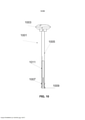
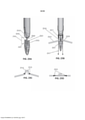
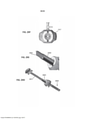
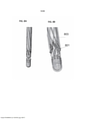
[023] a FIG. 1 é um desenho de uma parte distal de um trocáter, de acordo com alguns modelos da invenção;[023] FIG. 1 is a drawing of a distal portion of a trocar in accordance with some embodiments of the invention;
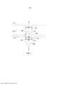
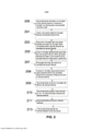
[024] a FIG. 2 é um fluxograma de um método para inserir um trocáter e conjunto externo num tecido para a aplicação da âncora, de acordo com alguns modelos da invenção;[024] FIG. 2 is a flow chart of a method for inserting a trocar and outer assembly into tissue for anchor application, in accordance with some embodiments of the invention;
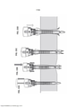
[025] as FIGURAS 3A-K são um conjunto que mostra um procedimento operativo de um trocáter e conjunto de cânula externa, de acordo com alguns modelos da invenção;[025] FIGURES 3A-K are an assembly showing an operative procedure of a trocar and external cannula assembly, according to some embodiments of the invention;
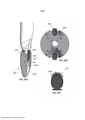
[026] as FIGURAS 4A-B são uma vista de perspetiva e uma vista de secção transversal de uma superfície numa parte distal de um trocáter que compreende saliências para melhorar o contacto com o tecido, de acordo com alguns modelos da invenção;[026] FIGURES 4A-B are a perspective view and a cross-sectional view of a surface on a distal portion of a trocar comprising protrusions to improve tissue contact, in accordance with some embodiments of the invention;
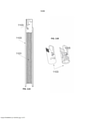
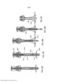
[027] as FIGURAS 5A -B são vistas laterais de uma parte distal de um trocáter que compreende uma estrutura de desdobrável expansível, de acordo com alguns modelos da invenção;[027] FIGURES 5A-B are side views of a distal part of a trocar comprising an expandable fold-out structure, according to some embodiments of the invention;
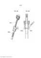
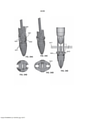
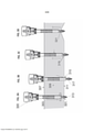
[028] as FIGURAS 6A-C são vistas de perspetiva de uma parte distal de um conjunto de trocáter e cânula externa integrado que compreende um mecanismo de aplicação da âncora paralelo, e uma vista alargada de uma âncora, de acordo com alguns modelos da invenção;[028] FIGURES 6A-C are perspective views of a distal portion of an integrated external trocar and cannula assembly comprising a parallel anchor application mechanism, and an enlarged view of an anchor, in accordance with some embodiments of the invention ;
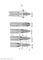
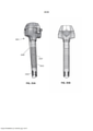
[029] as FIGURAS 7A-C são vistas de perspetiva de uma parte distal de um conjunto de trocáter e cânula externa integrado que compreende um mecanismo de aplicação da âncora arqueado, de acordo com alguns modelos da invenção;[029] FIGURES 7A-C are perspective views of a distal portion of an integrated external trocar and cannula assembly comprising an arcuate anchor application mechanism, in accordance with some embodiments of the invention;
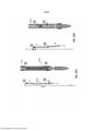
[030] as FIGURAS 8A-C são uma vista lateral e uma vista de perspetiva de uma parte distal de um conjunto de trocáter e cânula externa integrado que compreende várias âncoras, de acordo com alguns modelos da invenção;[030] FIGURES 8A-C are a side view and a perspective view of a distal portion of an integrated trocar and external cannula assembly comprising a number of anchors, in accordance with some embodiments of the invention;
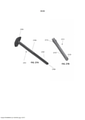
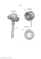
[031] as FIGURAS 9A-C são desenhos de um trocáter que compreende uma manga, e uma vista de perspetiva alargada e vista de secção transversal da manga, de acordo com alguns modelos da invenção;[031] FIGURES 9A-C are drawings of a trocar comprising a sleeve, and an enlarged perspective view and cross-sectional view of the sleeve, in accordance with some embodiments of the invention;
[032] a FIG. 10 é um desenho de um aplicador com base de roquete para a aplicação da âncora, de acordo com alguns modelos da invenção;[032] FIG. 10 is a drawing of a ratchet-based applicator for anchor application, in accordance with some embodiments of the invention;
[033] as FIGURAS 11A-B são desenhos de um elemento de mola acoplado a elementos impulsionadores para a aplicação da âncora, e uma vista alargada de um elemento deslizante posicionado no topo da mola, de acordo com alguns modelos da invenção;[033] FIGURES 11A-B are drawings of a spring element coupled to pusher elements for the application of the anchor, and an enlarged view of a sliding element positioned on top of the spring, according to some models of the invention;
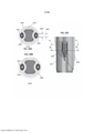
[034] a FIG. 12 é um desenho de uma cânula externa que compreende âncoras, de acordo com alguns modelos da invenção;[034] FIG. 12 is a drawing of an external cannula comprising anchors, in accordance with some embodiments of the invention;
[035] a FIG. 13 é uma vista de secção transversal de uma parte da cabeça da cânula externa, de acordo com alguns modelos da invenção;[035] FIG. 13 is a cross-sectional view of an external cannula head portion, in accordance with some embodiments of the invention;
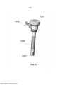
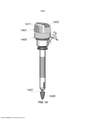
[036] a FIG. 14 é um desenho de um conjunto de trocáter e cânula externa integrado, de acordo com alguns modelos da invenção;[036] FIG. 14 is a drawing of an integrated external trocar and cannula assembly, in accordance with some embodiments of the invention;
[037] as FIGURAS 15A-D são um conjunto de desenhos que mostram o procedimento de aplicação, de acordo com alguns modelos da invenção;[037] FIGURES 15A-D are a set of drawings that show the application procedure, according to some models of the invention;
[038] as FIGURAS 16A-C são vistas de secção transversal que mostram a atuação de um mecanismo de roquete enquanto puxa para trás o aplicador da âncora, de acordo com alguns modelos da invenção;[038] FIGURES 16A-C are cross-sectional views showing the actuation of a ratchet mechanism while pulling back the anchor applicator, according to some models of the invention;
[039] as FIGURAS 17A-D são vistas laterais de uma parte distal (A-B) e vistas de secção transversal (C-D) do dispositivo durante a ativação do aplicador da âncora para aplicar âncoras, de acordo com alguns modelos da invenção;[039] FIGURES 17A-D are side views of a distal part (A-B) and cross-sectional views (C-D) of the device during activation of the anchor applicator to apply anchors, according to some embodiments of the invention;
[040] a FIG. 18 é uma vista de secção transversal do dispositivo depois de as âncoras terem sido aplicadas no tecido e antes da remoção do trocáter da cânula externa, de acordo com alguns modelos da invenção;[040] FIG. 18 is a cross-sectional view of the device after the anchors have been applied to the tissue and before the trocar is removed from the external cannula, in accordance with some embodiments of the invention;
[041] as FIGURAS 19A-B são desenhos que mostram a remoção do trocáter da cânula externa (A) e uma secção transversal do dispositivo durante a remoção (B), de acordo com alguns modelos da invenção;[041] FIGURES 19A-B are drawings showing the removal of the trocar from the external cannula (A) and a cross-section of the device during removal (B), according to some embodiments of the invention;
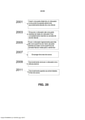
[042] a FIG. 20 é um fluxograma de um método para a aplicação da âncora usando um dispositivo para fechar feridas, de acordo com alguns modelos da invenção;[042] FIG. 20 is a flowchart of a method for applying the anchor using a wound closure device, in accordance with some embodiments of the invention;
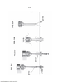
[043] as FIGURAS 21A-H são um conjunto que mostra um procedimento operativo de um dispositivo para fechar feridas, de acordo com alguns modelos da invenção;[043] FIGURES 21A-H are an assembly showing an operating procedure of a device for closing wounds, in accordance with some embodiments of the invention;
[044] a FIG. 22 mostra uma geometria exemplificativa de uma parte distal de um trocáter, de acordo com alguns modelos da invenção;[044] FIG. 22 shows exemplary geometry of a distal portion of a trocar, in accordance with some embodiments of the invention;
[045] a FIG. 23 mostra uma geometria exemplificativa de uma superfície configurada por baixo de uma parte estreita de um trocáter, de acordo com alguns modelos da invenção;[045] FIG. 23 shows exemplary geometry of a surface shaped beneath a narrow portion of a trocar, in accordance with some embodiments of the invention;
[046] as FIGURAS 24A-E são um conjunto que mostra um procedimento operativo de um obturador sem âncora para fechar feridas, de acordo com alguns modelos da invenção;[046] FIGURES 24A-E are an assembly showing an operative procedure of an anchorless obturator for closing wounds, in accordance with some embodiments of the invention;
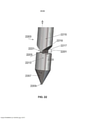
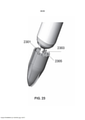
[047] as FIGURAS 25A-D mostram uma parte distal de um trocáter estruturado para fornecer um efeito de dobrar tecido (25A, 25B), e uma ilustração dos pontos de penetração das âncoras no tecido obtidos pela utilização do efeito de dobrar tecido (25C,25D), de acordo com alguns modelos da invenção;[047] FIGURES 25A-D show a distal portion of a trocar structured to provide a tissue bending effect (25A, 25B), and an illustration of tissue anchor penetration points obtained using the tissue bending effect (25C .25D), according to some models of the invention;
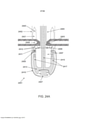
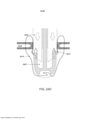
[048] as FIGURAS 26A-I ilustram um procedimento de aplicação de âncoras que envolve um efeito de dobrar tecido, e uma estrutura exemplificativa e mecanismo de operação de um trocáter e conjunto de cânula externa, de acordo com alguns modelos da invenção;[048] FIGURES 26A-I illustrate an anchor application procedure involving a tissue folding effect, and an exemplary structure and operating mechanism of a trocar and external cannula assembly, in accordance with some embodiments of the invention;
[049] as FIGURAS 27A-B mostram uma pega exemplificativa de um elemento deslizante de um trocáter, de acordo com alguns modelos da invenção;[049] FIGURES 27A-B show an exemplary handle of a sliding element of a trocar, according to some embodiments of the invention;
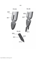
[050] as FIGURAS 28A-I são vários desenhos de âncora, de acordo com alguns modelos da invenção;[050] FIGURES 28A-I are various anchor designs, according to some embodiments of the invention;
[051] a FIG. 29A-F ilustra um acoplamento de cauda de andorinha entre a cânula externa e as âncoras (A-C), e uma configuração de alinhamento exemplificativa entre um trocáter e uma cânula externa (D-F), de acordo com alguns modelos da invenção;[051] FIG. 29A-F illustrate a dovetail coupling between the outer cannula and anchors (A-C), and an exemplary alignment configuration between a trocar and an outer cannula (D-F), in accordance with some embodiments of the invention;
[052] as FIGURAS 30A-C mostram um elemento de corte virado proximalmente de um trocáter, de acordo com alguns modelos da invenção;[052] FIGURES 30A-C show a proximally turned cutting element of a trocar, in accordance with some embodiments of the invention;
[053] as FIGURAS 31A-E ilustram um procedimento de aplicação de âncoras exemplificativo, no qual um elemento de corte virado proximalmente interage com uma âncora para penetrar o tecido, de acordo com alguns modelos da invenção;[053] FIGURES 31A-E illustrate an exemplary anchoring procedure in which a proximally turned cutting element interacts with an anchor to penetrate tissue, in accordance with some embodiments of the invention;
[054] as FIGURAS 32A-D ilustram um elemento impulsionador da âncora configurado para aplicar uma âncora a uma distância da haste do trocáter, de acordo com alguns modelos da invenção;[054] FIGURES 32A-D illustrate an anchor pusher element configured to apply an anchor at a distance from the trocar shaft, in accordance with some embodiments of the invention;
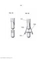
[055] as FIGURAS 33A-E mostram um trocáter que compreende um conjunto de asas rotativas configuradas para se estenderem radialmente para fora relativamente à haste do trocáter, de acordo com alguns modelos da invenção;[055] FIGURES 33A-E show a trocar comprising a set of rotating wings configured to extend radially outward relative to the trocar shaft, in accordance with some embodiments of the invention;
[056] as FIGURAS 34A-E mostram um trocáter que compreende uma estrutura axialmente extensível e compressível, de acordo com alguns modelos da invenção;[056] FIGURES 34A-E show a trocar comprising an axially extensible and compressible structure, in accordance with some embodiments of the invention;
[057] as FIGURAS 35A-E são uma vista isométrica e transversal (A-B), respetivamente, de uma cânula externa que compreende âncoras, e uma configuração exemplificativa de uma cânula externa que compreende bobinas de sutura (C-E), de acordo com alguns modelos da invenção;[057] FIGURES 35A-E are an isometric and cross-sectional view (AB), respectively, of an external cannula comprising anchors, and an exemplary configuration of an external cannula comprising suture coils (CE), according to some models of the invention;
[058] as FIGURAS 36A-B são fotografias de uma experiência ao vivo realizada num modelo suíno, usando um trocáter e conjunto de cânula externa, de acordo com alguns modelos da invenção;[058] FIGURES 36A-B are photographs of a live experiment performed on a porcine model, using a trocar and external cannula assembly, in accordance with some models of the invention;
[059] as FIGURAS 37A-F são fotografias de outra experiência ao vivo realizada num modelo suíno, usando um trocáter e conjunto de cânula externa, de acordo com alguns modelos da invenção; e[059] FIGURES 37A-F are photographs of another live experiment performed in a porcine model, using a trocar and external cannula assembly, in accordance with some models of the invention; and
[060] as FIGURAS 38A-C são uma configuração exemplificativa de um trocáter recebido dentro de uma cânula externa, em que a haste do trocáter não compreende uma parte estreita, de acordo com alguns modelos da invenção.[060] FIGURES 38A-C are an exemplary configuration of a trocar received within an external cannula, wherein the trocar shaft does not comprise a narrow portion, in accordance with some embodiments of the invention.
[061] DESCRIÇÃO DE MODELOS ESPECÍFICOS DA INVENÇÃO[061] DESCRIPTION OF SPECIFIC MODELS OF THE INVENTION
[062] A presente invenção, em alguns seus modelos, refere-se a um trocáter, e, mais em particular, mas não exclusivamente, a um conjunto de trocáter e cânula externa para usar num procedimento laparoscópico.[062] The present invention, in some of its models, relates to a trocar, and more particularly, but not exclusively, to a trocar and external cannula assembly for use in a laparoscopic procedure.
[063] Alguns modelos da invenção referem-se a um trocáter integrado e dispositivo para fechar feridas, compreendendo um trocáter e um conjunto de cânula externa. Alguns modelos da invenção referem-se a um dispositivo para fechar feridas que compreende um obturador, opcionalmente posicionável dentro de uma cânula externa.[063] Some models of the invention refer to an integrated trocar and wound closure device, comprising a trocar and an external cannula assembly. Some embodiments of the invention relate to a device for closing wounds which comprises an obturator, optionally positionable within an external cannula.
[064] Um aspeto amplo de alguns modelos da invenção refere-se à aplicação de âncoras e/ou suturas num tecido, por exemplo no tecido fascial de uma parede abdominal, para fechar uma ferida.[064] A broad aspect of some embodiments of the invention relates to the application of anchors and/or sutures to tissue, for example the fascial tissue of an abdominal wall, to close a wound.
[065] Um aspeto de alguns modelos refere-se a uma haste de trocáter que compreende um estreitamento na proximidade da extremidade distal do trocáter. Em alguns modelos, à medida que o trocáter é inserido na parede abdominal, a parte estreita é posicionada na camada de tecido fascial. Em alguns modelos, o estreitamento é suficientemente estreito para permitir que o tecido fascial salte para trás à volta dela. Opcionalmente, o estreitamento é formado por um ou mais recessos ao longo da haste que podem ser enchidos, pelo menos parcialmente, com tecido fascial. Em alguns modelos, o tecido é ativamente forçado para encher o recesso definido pela parte estreita.[065] One aspect of some models relates to a Trocar Stem that comprises a nip in the vicinity of the distal end of the Trocar. In some models, as the trocar is inserted into the abdominal wall, the narrow part is positioned in the fascial tissue layer. In some models, the nip is narrow enough to allow the fascial tissue to bounce back around it. Optionally, the nip is formed by one or more recesses along the shaft that can be filled, at least partially, with fascial tissue. In some models, the fabric is actively forced to fill the recess defined by the narrow part.
[066] Em alguns modelos, uma área de secção transversal do estreitamento é mais pequena do que uma área de secção transversal das partes da haste definida por cima e/ou por baixo do estreitamento, por exemplo 30% mais pequena, 50% mais pequena, 70% mais pequena, ou uma menor percentagem intermédia, superior ou inferior. Tal como foi referido aqui, uma área de secção transversal pode referir-se a uma área total, por exemplo se a haste compreender orifícios ou outros lúmens.[066] In some designs, a cross-sectional area of the nip is smaller than a cross-sectional area of the stem parts defined above and/or below the nip, e.g. 30% smaller, 50% smaller , 70% smaller, or a lower intermediate, higher or lower percentage. As mentioned herein, a cross-sectional area can refer to a total area, for example if the rod comprises holes or other lumens.
[067] Em alguns modelos, uma periferia da parte estreita é mais pequena do que uma periferia das partes da haste configuradas por cima e/ou por baixo da parte estreita. Opcionalmente, a periferia da parte estreita é suficientemente pequena para a fáscia introduzir um ou mais vazios definidos pela parte estreita. Em alguns modelos, uma forma circunscrita da parte estreita, por exemplo um círculo circunscrito, compreende um perímetro mais curto do que um perímetro de uma forma circunscrita das partes da haste configuradas por cima e/ou por baixo da parte estreita.[067] In some models, a periphery of the narrow part is smaller than a periphery of the rod parts configured above and/or below the narrow part. Optionally, the periphery of the narrow part is small enough for the fascia to introduce one or more voids defined by the narrow part. In some embodiments, a circumscribed shape of the narrow part, for example a circumscribed circle, comprises a perimeter shorter than a perimeter of a circumscribed shape of the shank parts configured above and/or below the narrow part.
[068] Em alguns modelos, a parte estreita é definida por um ou mais recessos. Opcionalmente, o um os recessos são configurados circunferencialmente ao longo das paredes da haste, formando concavidades ao longo de pelo menos uma parte da haste, por exemplo em paredes opostas da haste. Em alguns modelos, um recesso é iniciado a uma certa distância de um eixo longitudinal que percorre o centro da haste, por exemplo uma distância de 0,5 mm, 1 mm, 1,5 mm, 3 mm, 5 mm, ou qualquer distância intermédia, maior ou menor. Em alguns modelos, uma profundidade do recesso na direção radial (isto é, na direção do eixo longitudinal da haste) é suficientemente profunda para receber pelo menos uma parte do tecido fascial que salta para trás à volta da haste, por exemplo tendo uma profundidade de 1 mm, 2 mm, 3 mm, 4 mm, ou profundidades menores, intermédias ou maiores. Em alguns modelos, uma geometria do recesso é configurada de modo a caber numa peça relativamente plana ou reta da fáscia que entra no recesso. Em alguns modelos, um recesso é dimensionado de modo a preenche um diâmetro efetivo da haste, tal como um diâmetro de partes da haste configuradas por cima e/ou por baixo da parte estreita. Opcionalmente, por exemplo se a haste não for cilíndrica, o recesso é dimensionado para preencher uma configuração de contorno efetiva da haste.[068] In some models, the narrow part is defined by one or more recesses. Optionally, the recesses are configured circumferentially along the walls of the rod, forming concavities along at least a part of the rod, for example on opposite walls of the rod. In some models, a recess is started at a certain distance from a longitudinal axis running through the center of the shank, for example a distance of 0.5mm, 1mm, 1.5mm, 3mm, 5mm, or any distance intermediate, major or minor. In some designs, a recess depth in the radial direction (i.e., in the direction of the longitudinal axis of the rod) is deep enough to receive at least a portion of the fascial tissue that bounces back around the rod, for example having a depth of 1 mm, 2 mm, 3 mm, 4 mm, or smaller, intermediate or greater depths. In some models, a recess geometry is configured to fit a relatively flat or straight piece of fascia that enters the recess. In some designs, a recess is sized to fill an effective diameter of the shank, such as a diameter of portions of the shank configured above and/or below the narrow portion. Optionally, for example if the shank is not cylindrical, the recess is dimensioned to fill an effective contour configuration of the shank.
[069] Em alguns modelos, o estreitamento é suficientemente estreito para fazer com que o trocáter seja estabilizado na parede abdominal pela fáscia.[069] In some models, the narrowing is narrow enough to cause the trocar to be stabilized on the abdominal wall by the fascia.
[070] Em alguns modelos, as superfícies definidas pelo estreitamento, tal como as superfícies da haste por cima ou por baixo do estreitamento viradas para o estreitamento, fornecem um feedback sensível ao utilizador. Opcionalmente, o feedback é fornecido graças à resistência da superfície que encosta na fáscia.[070] In some models, surfaces defined by the nip, such as the stem surfaces above or below the nip facing the nip, provide sensitive feedback to the user. Optionally, feedback is provided thanks to the resistance of the surface touching the fascia.
[071] Em alguns modelos, um comprimento da parte estreita é suficientemente longo para permitir que a fáscia tenha uma certa espessura, tal como 0,5 mm, 1 mm, 3, mm, 5 mm, 1 cm, 2 cm, ou uma espessura intermédia, maior ou menor para pelo menos parcialmente introduzir um ou mais vazios definidos pela parte estreita. Em alguns modelos, um comprimento da parte estreita vai de 0,1 a 20 mm, de 0,1 a 40 mm, por exemplo de 0,1a 5 mm, de 6 a 10 mm, de 0,2 a 0,4 mm, de 4 a 7 mm, de 1 a 3 mm, ou intermédio, maior ou menor. Em alguns modelos, um comprimento da parte estreita da haste é suficientemente longo para fazer com que seja aplicada uma âncora administrada a partir de uma parte da haste por cima e/ou por baixo da parte estreita, ou a partir de uma cânula externa, na camada fascial. Opcionalmente, ao ser posicionada dentro da camada de tecido fascial, a parte estreita define um local da aplicação da âncora. Opcionalmente, ao controlar o posicionamento do trocáter, um utilizador pode controlar o local da aplicação da âncora, por exemplo garantir que as âncoras penetrem ou penetrem parcialmente através da fáscia. Opcionalmente, é controlada uma distância entre as âncoras aplicadas, por exemplo, uma distância entre duas âncoras opostamente aplicadas.[071] In some models, a length of the narrow part is long enough to allow the fascia to have a certain thickness, such as 0.5mm, 1mm, 3.mm, 5mm, 1cm, 2cm, or a intermediate, greater or lesser thickness to at least partially introduce one or more voids defined by the narrow part. On some models, a length of the narrow part is from 0.1 to 20 mm, from 0.1 to 40 mm, for example from 0.1 to 5 mm, from 6 to 10 mm, from 0.2 to 0.4 mm , from 4 to 7 mm, from 1 to 3 mm, or intermediate, larger or smaller. In some models, a length of the narrow part of the stem is long enough to cause an anchor to be delivered from a part of the stem above and/or below the narrow part, or from an external cannula, in the fascial layer. Optionally, when positioned within the fascial tissue layer, the narrow portion defines an anchor application site. Optionally, by controlling the placement of the trocar, a user can control the location of the anchor application, for example ensuring that the anchors penetrate or partially penetrate through the fascia. Optionally, a distance between applied anchors is controlled, for example, a distance between two oppositely applied anchors.
[072] Em alguns modelos, por exemplo se a haste tiver um perfil circular, um diâmetro da parte estreita da haste é pelo menos 50% mais pequeno do que um diâmetro das partes da haste do trocáter configuradas por cima e/ou por baixo da parte estreita. Em alguns modelos, uma abertura (isto é, uma ferida) formada no tecido, por exemplo através da incisão e opcionalmente expansão da abertura, está dimensionada de modo a que a fáscia salte para trás à volta da parte estreita. Opcionalmente, a abertura é expandida aquando a inserção das partes mais largas da haste, tais como partes por cima e/ou por baixo da parte estreita, e quando a parte estreita está posicionada na fáscia, o tecido que delimita a abertura salta elasticamente para trás, regressando assim ou regressando parcialmente para a abertura originalmente dimensionada. Opcionalmente, o salto para trás do tecido estabiliza o trocáter na posição. Uma vez que o salto para trás do tecido está associado à elasticidade do tecido, a extensão do salto para trás pode variar, por exemplo, entre os pacientes. Opcionalmente, a parte estreita é suficientemente estreita para que, mesmos em pacientes nos quais a extensão do salto para trás do tecido é relativamente pequena, ocorra pelo menos algum salto para trás. Adicionalmente ou em alternativa, uma superfície virada proximalmente por baixo da parte estreita engata o tecido de um modo que, mesmo o salto para trás não ocorra ou ocorra apenas ligeiramente, o trocáter é estabilizado na posição através da superfície virada proximalmente apegada ao tecido.[072] In some models, for example if the stem has a circular profile, a diameter of the narrow part of the stem is at least 50% smaller than a diameter of the parts of the trocar stem configured above and/or below the narrow part. In some designs, an opening (i.e., a wound) formed in the tissue, for example by incising and optionally expanding the opening, is sized so that the fascia springs back around the narrow part. Optionally, the opening is expanded when the wider parts of the nail are inserted, such as parts above and/or below the narrow part, and when the narrow part is positioned in the fascia, the tissue delimiting the opening elastically springs back , thus returning or partially returning to the originally sized opening. Optionally, fabric bounce back stabilizes the trocar in position. Since tissue bounce back is associated with tissue elasticity, the extent of bounce back may vary, for example, between patients. Optionally, the narrow portion is narrow enough that even in patients in whom the extent of tissue bounce back is relatively small, at least some bounce back occurs. Additionally or alternatively, a proximally facing surface beneath the narrow portion engages the tissue in such a way that, even if the backward hop does not occur or occurs only slightly, the trocar is stabilized in position by the proximally facing surface attached to the tissue.
[073] Em alguns modelos, as superfícies da haste definidas pela parte estreita, que estão viradas para a parte estreita, resistem à remoção do tecido fascial a partir da parte estreita. Opcionalmente, ao posicionar o trocáter de modo a que a fáscia circunde a parte estreita, um utilizador enfrenta uma resistência maior ao puxar ou empurrar o trocáter, em que a resistência causada pelas superfícies encosta à fáscia.[073] In some models, the nail surfaces defined by the narrow end, which face the narrow end, resist removal of fascial tissue from the narrow end. Optionally, by positioning the trocar so that the fascia surrounds the narrow portion, a user faces greater resistance when pulling or pushing the trocar, wherein the resistance caused by the surfaces abuts the fascia.
[074] Em alguns modelos, a resistência é fornecida pela superfície virada proximalmente da haste do trocáter por baixo da parte estreita. Em alguns modelos, a superfície virada proximalmente compreende um tecido que engata geometricamente e que é eficaz para reduzir ou evitar o movimento do tecido recebido dentro do recesso, tal como o movimento radialmente para fora do tecido, para longe do recesso. Em alguns modelos, o contacto entre a superfície da haste virada proximalmente e uma superfície da fáscia de frente para a direção abdominal é melhorado por fricção, por exemplo sendo a superfície da haste texturada, tal como com um padrão discreto ou contínuo, por exemplo um padrão ondulado da superfície ou qualquer outro tipo de padrão adequado para melhorar a fricção.[074] In some models, resistance is provided by the proximally facing surface of the trocar shaft beneath the narrow part. In some embodiments, the proximally facing surface comprises a fabric which geometrically engages and which is effective to reduce or prevent movement of the fabric received within the recess, such as movement radially outward from the fabric away from the recess. In some models, contact between the proximally facing surface of the rod and a fascia surface facing the abdominal direction is improved by friction, for example the surface of the rod being textured, such as with a discrete or continuous pattern, for example a wavy surface pattern or any other pattern suitable for improving friction.
[075] Em alguns modelos, a superfície da haste virada proximalmente é adaptada para pelo menos entrar no tecido fascial, por exemplo possuindo uma ou mais saliências apontadas para o tecido fascial. Opcionalmente, as saliências picam a camada fascial e pode também podem picar e/ou passar através do peritoneu adjacente à fáscia. Em alguns modelos, a remoção indesejada do trocáter do abdómen é evitada graças à resistência causada pela superfície virada proximalmente da haste que é segurada contra o tecido fascial. Em alguns modelos, a superfície virada proximalmente da haste compreende uma geometria relativamente plana, por exemplo, para fornecer uma maior resistência quando se puxa o trocáter na direção proximal. Em alternativa, a superfície virada proximalmente é angulada, inclinada, com uma forma hemisférica ou com outra forma.[075] In some models, the proximally facing surface of the rod is adapted to at least enter the fascial tissue, for example having one or more protrusions pointing into the fascial tissue. Optionally, the protrusions puncture the fascial layer and may also puncture and/or pass through the peritoneum adjacent to the fascia. In some models, unwanted removal of the trocar from the abdomen is avoided thanks to the resistance caused by the proximally turned surface of the nail that is held against the fascial tissue. In some designs, the proximally facing surface of the nail comprises a relatively flat geometry, for example, to provide greater resistance when pulling the trocar in the proximal direction. Alternatively, the proximally facing surface is angled, angled, hemispherical or otherwise shaped.
[076] Em alguns modelos, a geometria do trocáter indica um posicionamento atual do trocáter dentro do tecido. Por exemplo, em alguns modelos, um utilizador, como um cirurgião, consegue detetar a profundidade de inserção atual do trocáter ao encontrar a resistência que se forma à medida que as partes mais largas da haste por cima e por baixo da parte estreita são empurradas pela ferida. Isto pode ser vantajoso nos casos em que a inserção do trocáter é realizada às cegas (ou seja, nos casos em que um cirurgião não consegue identificar visualmente as camadas do tecido, diretamente e/ou usando um dispositivo de imagens).[076] In some models, the trocar geometry indicates a current placement of the trocar within the tissue. For example, in some models, a user, such as a surgeon, can detect the current insertion depth of the trocar by finding the resistance that forms as the wider parts of the stem above and below the narrow part are pushed by the wound. This can be advantageous in cases where trocar insertion is performed blindly (ie, in cases where a surgeon cannot visually identify tissue layers, directly and/or using an imaging device).
[077] Em alguns modelos, a haste do trocáter compreende uma parte final distal, seguida por uma parte mais estreita. Opcionalmente, a união ou ponto de mudança entre a parte da extremidade distal e a parte estreita define uma superfície configurada para encostar na fáscia. Opcionalmente, a parte estreita é seguida, na direção proximal, por um elemento configurado para resistir ao movimento do trocáter mais fundo na direção abdominal. Opcionalmente, o elemento resistente é uma parte da haste mais larga ou que alarga. Opcionalmente, o elemento resistente fornece uma indicação sensível a um utilizador sobre o posicionamento atual do trocáter, por exemplo relativamente à fáscia.[077] In some models, the trocar shaft comprises a distal end part, followed by a narrower part. Optionally, the junction or switching point between the distal end portion and the narrow portion defines a surface configured to abut the fascia. Optionally, the narrow part is followed, in the proximal direction, by an element configured to resist movement of the deeper trocar in the abdominal direction. Optionally, the resistant element is a wider or widening part of the shank. Optionally, the resistant element provides a sensitive indication to a user of the current positioning of the trocar, for example relative to the fascia.
[078] Um aspeto de alguns modelos refere-se a um conjunto de trocáter e cânula externa que compreende elementos impulsionadores da âncora para a aplicação da âncora. Em alguns modelos, um elemento impulsionador da âncora é um elemento formado e/ou dimensionado e/ou posicionado numa configuração adequado para engatar uma âncora, para avançar na direção do tecido e/ou dentro do tecido. Em alguns modelos, os elementos impulsionadores da âncora são retráteis manualmente e/ou automaticamente, por exemplo utilizando um conjunto de mola que retrai os elementos impulsionadores assim que as âncoras estiverem posicionadas no tecido fascial, por exemplo posicionadas por baixo da camada fascial. Em alguns modelos, os elementos impulsionadores da âncora estão configurados paralelamente a um eixo longitudinal da haste do trocáter.[078] One aspect of some models refers to a trocar and external cannula assembly comprising anchor booster elements for anchor application. In some designs, an anchor-driver element is an element formed and/or sized and/or positioned in a configuration suitable for engaging an anchor, for advancing toward the fabric and/or into the fabric. In some models, the anchor pusher elements are manually and/or automatically retractable, for example using a spring assembly that retracts the pusher elements once the anchors are positioned in the fascial tissue, for example positioned beneath the fascial layer. In some models, the driving elements of the anchor are configured parallel to a longitudinal axis of the trocar shaft.
[079] Em alternativa, os elementos impulsionadores da âncora são arqueados à volta da haste do trocáter, para aplicar âncoras num ângulo relativamente a um eixo longitudinal da haste do trocáter, aumentando opcionalmente uma distância entre as âncoras aplicadas. Note-se que em alguns modelos, o elemento impulsionador da âncora tem necessariamente de "impulsionar" a âncora em direção ao tecido, engatando apenas a âncora e/ou fazendo com que ela avance. [079] Em alguns modelos, o trocáter é usado com várias cânulas externas, para fechar várias feridas, por exemplo inserindo um único trocáter sempre numa cânula externa diferente localizada numa porta abdominal, e aplicando âncoras para fechar a ferida em cada porta.[079] Alternatively, the anchor driving elements are arched around the trocar shaft, to apply anchors at an angle to a longitudinal axis of the trocar shaft, optionally increasing a distance between the applied anchors. Note that in some models, the anchor driving element must necessarily "push" the anchor towards the fabric, engaging only the anchor and/or causing it to advance. [079] In some models, the trocar is used with several external cannulas to close multiple wounds, for example by inserting a single trocar always into a different external cannula located in an abdominal port, and applying anchors to close the wound at each port.
[080] Um aspeto de alguns modelos refere-se a um conjunto de trocáter e cânula externa configurado para aplicar âncoras distantes umas das outras através da formação de uma dobra de tecido que aproxima temporariamente os pontos de penetração no tecido. Em alguns modelos, o efeito da dobra de tecido permite avançar âncoras substancialmente em paralelo à haste do trocáter, mas aplicando âncoras a uma distância da haste do trocáter e/ou a uma distância umas das outras.[080] One aspect of some models refers to a trocar and external cannula assembly configured to apply anchors distant from each other by forming a tissue fold that temporarily approximates the tissue penetration points. In some models, the effect of tissue folding allows anchors to be advanced substantially parallel to the trocar shaft, but applying anchors at a distance from the trocar shaft and/or at a distance from each other.
[081] Em alguns modelos, o tecido é apertado para uma forma em U substancialmente invertida. Opcionalmente, o tecido é penetrado em bases opostas da forma em U invertido, por exemplo através das âncoras. Em alguns modelos, o tecido é apertado entre a parte estreita do trocáter e uma âncora e/ou entre a parte estreita do trocáter e um elemento impulsionador da âncora. Opcionalmente, antes da penetração, o avanço da âncora numa direção distal empurra o tecido contra a parte estreita, formando a dobra do tecido. Opcionalmente, a dobra do tecido é simetricamente formada em lados opostos da haste do trocáter através do avanço de âncoras opostas. Em alguns modelos, pelo menos uma parte da haste do trocáter está configurada no centro da forma em U invertido, evitando potencialmente que uma âncora penetre pelo lado oposto da dobra.[081] In some models, the fabric is tightened to a substantially inverted U-shape. Optionally, the fabric is penetrated at opposing bases of the inverted U-shape, for example through the anchors. In some models, the tissue is clamped between the narrow part of the trocar and an anchor and/or between the narrow part of the trocar and an anchor driving element. Optionally, prior to penetration, advancing the anchor in a distal direction pushes the tissue against the narrow part, forming the tissue fold. Optionally, the tissue fold is symmetrically formed on opposite sides of the trocar shaft by advancing opposing anchors. In some models, at least a portion of the trocar shaft is configured in the center of the inverted U-shape, potentially preventing an anchor from penetrating the opposite side of the bend.
[082] Adicionalmente ou em alternativa ao tecido apertado entre as âncoras e/ou elemento impulsionador da âncora e a parte estreita, uma parte da haste proximal do trocáter pode compreender uma ou mais extensões alinhadas pelo menos em parte com a parte estreita, permitindo que o tecido seja apertado entre a extensão da haste e a parte estreita.[082] In addition to or as an alternative to the tight tissue between the anchors and/or anchor driving element and the narrow part, a part of the proximal rod of the trocar may comprise one or more extensions aligned at least in part with the narrow part, allowing the fabric is tightened between the extension of the rod and the narrow part.
[083] Um aspeto de alguns modelos refere-se a um conjunto de cânula externa acionada por mola, no qual a mola não oferece resistência contra a aplicação da âncora. Uma potencial vantagem do avanço das âncoras no tecido sem encontrar resistência da mola pode consistir em proporcionar uma maior deteção e/ou controlo por parte de um utilizador, tal como um cirurgião que está a operar o trocáter, uma vez que a resistência sentida pelo utilizador é unicamente a resistência do tecido, contrariamente a uma resistência combinada do tecido e da mola.[083] One aspect of some models refers to a spring-loaded external cannula assembly, in which the spring offers no resistance against the application of the anchor. A potential advantage of advancing tissue anchors without encountering spring resistance may be to provide greater detection and/or control by a user, such as a surgeon operating the trocar, as the resistance felt by the user it is just the strength of the fabric, as opposed to a combined strength of the fabric and the spring.
[084] Em alguns modelos, a mola é posicionada para fornecer um mecanismo “contração” que automaticamente retrai os elementos impulsionadores da âncora numa direção proximal, deixando as âncoras aplicadas no tecido.[084] In some models, the spring is positioned to provide a “contraction” mechanism that automatically retracts the anchor driving elements in a proximal direction, leaving the anchors applied to the tissue.
[085] Um aspeto dos modelos refere-se a um conjunto de trocáter e cânula externa que compreende um diâmetro máximo (p. ex. um diâmetro da cânula externa que circunda a haste do trocáter) que é inferior a, por exemplo, 30 mm, 20 mm, 40 mm, ou a diâmetros intermédios, maiores ou menores. Em alguns modelos, vários componentes do dispositivo são acoplados entre si numa disposição que mantém todos os componentes dentro dos limites do diâmetro máximo. Em alguns modelos, os componentes do dispositivo estão configurados para caberem um dentro do outro, por exemplo um elemento deslizante do trocáter é pelo menos parcialmente recebido dentro de um lúmen de uma pega do trocáter. Noutro exemplo, a cânula externa compreende um ou mais recessos formados e/ou dimensionados para receber pelo menos uma parte de uma âncora. Opcionalmente, o recesso define um acoplamento de cauda de andorinha entre a âncora e a cânula externa.[085] One aspect of the models relates to a trocar and outer cannula assembly comprising a maximum diameter (e.g. a diameter of the outer cannula surrounding the trocar shaft) that is less than, for example, 30 mm , 20 mm, 40 mm, or to intermediate, larger or smaller diameters. In some models, several components of the device are coupled together in an arrangement that keeps all components within the limits of the maximum diameter. In some models, the components of the device are configured to fit within one another, for example a trocar slide is at least partially received within a lumen of a trocar handle. In another example, the external cannula comprises one or more recesses formed and/or sized to receive at least a portion of an anchor. Optionally, the recess defines a dovetail coupling between the anchor and the outer cannula.
[086] Um aspeto de alguns modelos refere-se a um trocáter que compreende um ou mais elementos virados proximalmente, configurado para interagir com a âncora para ajudar a âncora na penetração do tecido. Em alguns modelos, o elemento virado proximalmente entra em contacto com o tecido a partir de uma direção substancialmente oposta da âncora. Em alguns modelos, o elemento virado proximalmente compreende um bordo e/ou ponta de corte adequada para cortar tecido, por exemplo quando a âncora avança pelo bordo do elemento virado proximalmente. Em alguns modelos, o tecido apanhado entre o elemento de corte e a âncora é cortado num efeito tipo tesoura à medida que a âncora avança pelo bordo de corte. Adicionalmente ou em alternativa, uma ponta de corte do elemento é configurada para furar o tecido. Adicionalmente ou em alternativa, uma ponta de corte do elemento é configurada para perfurar um orifício no tecido.[086] One aspect of some models refers to a trocar comprising one or more proximally facing elements configured to interact with the anchor to aid the anchor in tissue penetration. In some designs, the proximally turned element contacts tissue from a direction substantially opposite to the anchor. In some designs, the proximally turned element comprises a cutting edge and/or tip suitable for cutting tissue, for example when the anchor advances over the edge of the proximally turned element. In some models, the fabric caught between the cutting element and the anchor is cut in a scissor-like effect as the anchor advances along the cutting edge. Additionally or alternatively, a cutting edge of the element is configured to pierce the fabric. Additionally or alternatively, a cutting edge of the element is configured to punch a hole in the fabric.
[087] Um aspeto de alguns modelos refere-se a um conjunto de trocáter e cânula externa, no qual a cânula externa compreende âncoras e/ou suturas e o trocáter compreende um mecanismo para engatar as âncoras para aplicá-las no tecido. Em alguns modelos, um acoplamento entre as âncoras e a cânula externa proporciona a inserção do trocáter na cânula, por exemplo para obter uma configuração "pronta a usar" do conjunto, sem causar um avanço indesejado das âncoras distalmente (p. ex. avanço das âncoras antes de uma parte distal do dispositivo ter sido introduzida pela fáscia). Em alguns modelos, as âncoras são fixadas numa posição relativamente à cânula externa através de um acoplamento de cauda de andorinha, até serem engatadas por elementos impulsionadores da âncora que se estendem externamente desde a haste do trocáter durante a operação para entrarem em contacto com as âncoras e avançá-las para dentro do tecido. Uma potencial vantagem de um mecanismo de avanço da âncora que está separado das âncoras na cânula externa pode consistir na capacidade de reutilizar um trocáter com várias cânulas externas (p. ex. através da introdução do trocáter sempre numa cânula diferente). Isto pode ser especialmente vantajoso em procedimentos, nos quais são criadas várias portas no abdómen e várias cânulas externas são posicionadas nas portas para permitir a passagem de um laparoscópio. Outra potencial vantagem do trocáter com um mecanismo de avanço da âncora integrado pode consistir numa cânula externa com uma estrutura simples e eficiente em termos de custos, por exemplo relativamente a uma cânula externa, na qual pelo menos uma parte do mecanismo de avanço da âncora está integrada na própria cânula. Outra potencial vantagem de um trocáter com um mecanismo de avanço da âncora integrado, que está configurado para engatar âncoras e/ou suturas acopladas a uma cânula externa, pode consistir nas dimensões de um conjunto (p. ex. diâmetro total, comprimento) que não excedem as de um trocáter padrão e conjunto de cânula, exceto que o trocáter e o conjunto de cânula de acordo com alguns modelos da invenção já incluem o mecanismo de aplicação de âncoras e/ou suturas integrado dentro do conjunto. Opcionalmente, ao ter todos os componentes do mecanismos de aplicação, tais como os elementos impulsionadores da âncora, âncoras, elemento deslizante que aciona o avanço, e/ou outros elementos dentro dos limites do conjunto (p. ex. sem ter componentes que sobressaem radialmente para fora da cânula), uma periferia do conjunto compreende um perfil suave e arredondado que pode ser eficaz para reduzir o rasgo do tecido, tal como durante a penetração, e permitir a inserção do conjunto por uma ferida relativamente pequena.[087] One aspect of some models refers to a trocar and external cannula assembly, in which the external cannula comprises anchors and/or sutures and the trocar comprises a mechanism for engaging the anchors to apply them to the tissue. In some models, a coupling between the anchors and the external cannula provides for insertion of the trocar into the cannula, e.g. to obtain an "ready-to-use" configuration of the set, without causing undesired advancement of the anchors distally (e.g. advancement of the anchors before a distal part of the device has been introduced through the fascia). In some models, the anchors are fixed in position relative to the external cannula via a dovetail coupling, until they are engaged by anchor pusher elements that extend externally from the trocar shaft during operation to come into contact with the anchors. and advance them into the fabric. A potential advantage of an anchor advancement mechanism that is separate from the anchors in the external cannula may be the ability to reuse a trocar with multiple external cannulas (eg, by always introducing the trocar into a different cannula). This can be especially advantageous in procedures where multiple ports are created in the abdomen and multiple external cannulas are positioned in the ports to allow passage of a laparoscope. Another potential advantage of the trocar with an integrated anchor advancement mechanism may consist of an external cannula with a simple and cost-effective structure, for example over an external cannula, in which at least a part of the anchor advancement mechanism is integrated into the cannula itself. Another potential advantage of a trocar with an integrated anchor advancement mechanism, which is configured to engage anchors and/or sutures attached to an external cannula, may consist of an assembly's dimensions (e.g., overall diameter, length) that do not exceed those of a standard trocar and cannula assembly, except that the trocar and cannula assembly according to some embodiments of the invention already include the anchor and/or suture application mechanism integrated within the assembly. Optionally, by having all components of the application mechanism, such as anchor driving elements, anchors, slider that drives the feed, and/or other elements within the limits of the set (e.g. without having components that protrude radially out of the cannula), one periphery of the set comprises a smooth, rounded profile that can be effective to reduce tissue tearing, such as during penetration, and allow insertion of the set through a relatively small wound.
[088] Uma potencial vantagem da aplicação das âncoras e/ou suturas usando um trocáter e/ou conjunto de trocáter e cânula externa por exemplo conforme descrito aqui pode consistir em aplicar as âncoras e/ou suturas a uma profundidade limitada e predefinida do tecido. Outra potencial vantagem pode consistir em aplicar as âncoras e/ou sutura enquanto o trocáter está retido numa posição estável pelo tecido fascial que circunda a parte estreita, reduzindo assim o risco de aplicas as âncoras numa posição não desejada relativamente ao dispositivo. Outra potencial vantagem pode consistir no controlo contínuo sobre o processo de aplicação de âncoras e/ou suturas através do movimento da pega, que por sua vez é eficaz para avançar os elementos impulsionadores da âncora na direção do tecido. Outra potencial vantagem de um mecanismo de aplicação por exemplo conforme descrito aqui pode consistir num mecanismo baseado no movimento linear, axial dos componentes, potencialmente simplificando a operação de um utilizador.[088] A potential advantage of applying anchors and/or sutures using a trocar and/or trocar and external cannula set for example as described here may be to apply the anchors and/or sutures to a limited and predefined depth of tissue. Another potential advantage may be to apply the anchors and/or suture while the trocar is retained in a stable position by the fascial tissue that surrounds the narrow part, thus reducing the risk of applying the anchors in an undesired position with respect to the device. Another potential advantage may be the continuous control over the anchor and/or suture application process through the movement of the handle, which in turn is effective in advancing the anchor driving elements towards the tissue. Another potential advantage of an application mechanism for example as described herein may be a mechanism based on linear, axial movement of components, potentially simplifying a user's operation.
[089] O termo “trocáter”, conforme referido em alguns modelos da invenção, refere-se a um instrumento cirúrgico adaptado para inserção através da parede abdominal. Em alguns modelos, o instrumento compreende uma ponta distal afiada, por exemplo para incisão através do tecido e/ou para expandir uma ferida. Em alternativa, o instrumento compreende uma ponta romba. Opcionalmente, o instrumento compreende uma ponta afiada blindada. Em alguns modelos, o instrumento pode ser inserido numa cânula. Em alguns modelos, o instrumento está configurado para engatar âncoras e/ou suturas que estão englobadas dentro da cânula externa para aplicá-la.[089] The term "trocater", as referred to in some models of the invention, refers to a surgical instrument adapted for insertion through the abdominal wall. In some designs, the instrument comprises a sharp distal tip, for example for incising through tissue and/or for expanding a wound. Alternatively, the instrument comprises a blunt tip. Optionally, the instrument comprises a shielded sharp tip. In some models, the instrument can be inserted into a cannula. In some models, the instrument is configured to engage anchors and/or sutures that are enclosed within the external cannula for delivery.
[090] O termo “conjunto de trocáter e cânula externa”, conforme referido em alguns modelos da invenção, pode referir-se a um a trocáter posicionado dentro de uma cânula externa. Em alguns modelos, o conjunto de trocáter e cânula externa compreende um mecanismo de aplicação de âncoras integrado. Note- se que o termo “conjunto” pode referir-se a um ou ambos os componentes do conjunto.[090] The term "trocater and external cannula assembly", as referred to in some models of the invention, may refer to a trocar positioned within an external cannula. In some models, the trocar and external cannula assembly comprises an integrated anchoring mechanism. Note that the term “set” can refer to one or both components of the set.
[091] O termo “obturador”, conforme referido em alguns modelos da invenção, refere-se a um instrumento cirúrgico adaptado para inserção através da parede abdominal, para fechar feridas. Opcionalmente, o instrumento é inserido através de uma ferida existente. Em alguns modelos, o instrumento compreende âncoras e/ou suturas para aplicação no tecido. Em alguns modelos, o instrumento pode ser inserido por uma cânula externa. Opcionalmente, em modelos nos quais o próprio obturador compreende âncoras e/ou suturas, a cânula externa não compreende âncora e/ou suturas. Em alguns modelos, o instrumento compreende uma ponta romba.[091] The term "obturator", as referred to in some embodiments of the invention, refers to a surgical instrument adapted for insertion through the abdominal wall to close wounds. Optionally, the instrument is inserted through an existing wound. In some models, the instrument comprises anchors and/or sutures for application to tissue. In some models, the instrument can be inserted through an external cannula. Optionally, in models in which the obturator itself comprises anchors and/or sutures, the external cannula does not comprise anchor and/or sutures. In some models, the instrument comprises a blunt tip.
[092] O termo “camada fascial”, conforme referido em alguns modelos da invenção, pode referir-se a um ou mais tecidos fasciais, tecido peritoneu adjacente à fáscia, camada de gordura adjacente à fáscia, camada de gordura entre o peritoneu e a fáscia, e/ou qualquer combinação de tecido abdominal.[092] The term "fascial layer", as referred to in some models of the invention, may refer to one or more fascial tissues, peritoneum tissue adjacent to the fascia, layer of fat adjacent to the fascia, layer of fat between the peritoneum and the fascia, and/or any combination of abdominal tissue.
[093] Antes de explicar pelo menos um modelo da invenção em detalhe, deve entender-se que a invenção não está necessariamente limitada na sua aplicação aos detalhes de construção e à disposição dos componentes e/ou métodos definidos na seguinte descrição e/ou ilustrados nos desenhos e/ou Exemplos. A invenção é capaz de outros modelos ou de ser praticada ou levada a cabo de várias maneiras.[093] Before explaining at least one embodiment of the invention in detail, it should be understood that the invention is not necessarily limited in its application to the construction details and arrangement of components and/or methods defined in the following description and/or illustrated. in the drawings and/or Examples. The invention is capable of other models or of being practiced or carried out in various ways.
[094] Antes de explicar pelo menos um modelo da invenção em detalhe, deve entender-se que a invenção não está necessariamente limitada na sua aplicação aos detalhes definidos na seguinte descrição ou exemplificados pelos Exemplos. A invenção é capaz de outros modelos ou de ser praticada ou levada a cabo de várias maneiras.[094] Before explaining at least one embodiment of the invention in detail, it should be understood that the invention is not necessarily limited in its application to the details defined in the following description or exemplified by the Examples. The invention is capable of other models or of being practiced or carried out in various ways.
[095] Antes de explicar pelo menos um modelo da invenção em detalhe, deve entender-se que que qualquer descrição relacionada com um trocáter, conforme aqui referido, também pode ser aplicada a um dispositivo de fecho, conforme referido aqui, ou vice-versa.[095] Before explaining at least one embodiment of the invention in detail, it should be understood that any description relating to a trocar, as referred to herein, may also apply to a closure device, as referred to herein, or vice versa. .
[096] Uma descrição geral de uma parte distal de um trocáter[096] A general description of a distal part of a trocar
[097] Relativamente aos desenhos, a Figura 1 ilustra uma parte distal de um trocáter, de acordo com alguns modelos da invenção.[097] With reference to the drawings, Figure 1 illustrates a distal part of a trocar, according to some models of the invention.
[098] Em alguns modelos, o trocáter compreende uma haste 101. Em alguns modelos, a haste 101 compreende pelo menos uma parte 103 que é mais estreita do que as partes da haste definidas por cima e/ou por baixo da parte estreita, tal como a parte 105 e 107. Em alguns modelos, uma área de secção transversal da parte estreita 103 é mais pequena do que uma área de secção transversal das partes da haste 105 e/ou 107, por exemplo 30% mais pequena, 50% mais pequena, 60% mais pequena, 70% mais pequena, ou menores percentagens intermédias, superiores ou inferiores.[098] In some models, the trocar comprises a
[099] Em alguns modelos, a haste 101 é cilíndrica. Opcionalmente, a parte estreita 103 tem um diâmetro mais curto do que um diâmetro das partes da haste definidas pela parte estreita, tal como a parte 105 e a parte 107.[099] In some models, the
[100] Adicionalmente ou em alternativa, em alguns modelos, a haste 101 compreende um ou mais recessos que formam a parte estreita. Opcionalmente, os recessos são dimensionados para receber tecido fascial. Em alguns modelos, os recessos são definidos circunferencialmente à volta da haste. Em alternativa, os recessos são definidos ao longo das partes da haste, por exemplo abrangendo180 graus, 270 graus, ou partes intermédias, maiores ou menores da circunferência da haste. Por exemplo, dois recessos podem ser configurados ao longo de paredes opostas da haste.[100] Additionally or alternatively, in some designs, the
[101] Em alguns modelos, um recesso é iniciado a uma certa distância de um eixo longitudinal que percorre o centro da haste, por exemplo uma distância de 0,5 mm, 1 mm, 1,5 mm, 3 mm ou qualquer distância intermédia, maior ou menor. Em alguns modelos, uma profundidade do recesso na direção radial (isto é, na direção do eixo longitudinal da haste) é suficientemente profunda para receber pelo menos uma parte do tecido fascial que salta para trás à volta da haste, por exemplo tendo uma profundidade de 1 mm, 2 mm, 3 mm, 5 mm, ou profundidades menores, intermédias ou maiores. Opcionalmente, uma profundidade do recesso é determinada para estreitar uma parte da haste para permitir que a fáscia salte para trás à sua volta, mas deixa uma distância suficiente do eixo AA’ para a iniciação do recesso, de modo a que a parte estreita que se formou permaneça suficientemente rígida, por exemplo para transformar a força de uma extremidade proximal para uma extremidade distal do trocáter.[101] In some models, a recess starts at a distance from a longitudinal axis running through the center of the shank, for example a distance of 0.5mm, 1mm, 1.5mm, 3mm or any distance in between , bigger or smaller. In some designs, a recess depth in the radial direction (i.e., in the direction of the longitudinal axis of the rod) is deep enough to receive at least a portion of the fascial tissue that bounces back around the rod, for example having a depth of 1 mm, 2 mm, 3 mm, 5 mm, or smaller, intermediate or greater depths. Optionally, a recess depth is determined to narrow a portion of the stem to allow the fascia to spring back around it, but leave sufficient distance from the axis AA' for recess initiation so that the narrow portion that formed remains sufficiently rigid, for example to transform force from a proximal to a distal end of the trocar.
[102] Em alguns modelos, uma geometria do recesso é configurada de modo a caber numa peça relativamente plana ou reta da fáscia que entra no recesso. Em alguns modelos, a parte estreita é proximal a uma ponta distal 109 do trocáter. Por exemplo, uma distância entre a superfície virada proximalmente 113 da haste definida pela parte estreita e a extremidade da ponta distal 109 vai de 5 a 50 mm, tal como 15 mm, 30 mm, 45 mm.[102] In some models, a recess geometry is configured to fit a relatively flat or straight piece of fascia that enters the recess. In some models, the narrow part is proximal to a
[103] Em alguns modelos, as paredes da parte da haste 105 por cima da parte estreita são inclinadas, por exemplo como se pode ver em 121, formando assim uma parte afunilada. Opcionalmente, as paredes são inclinadas a um ângulo de, por exemplo, 20-80 graus, tal como 30 graus, 60 graus, 70 graus relativamente a um eixo longitudinal da haste do trocáter. As paredes inclinadas facilitam a inserção do trocáter na parede abdominal.[103] In some designs, the walls of the
[104] Em alguns modelos, a ponta distal 109 é afunilada. Em alguns modelos, a ponta distal 109 é uma ponta afiada, configurada para perfurar uma ferida através de uma parede abdominal. Em alternativa, a ponta 109 é uma ponta romba, que pode ser inserida através de uma ferida existente ou porta na parede abdominal. Em alguns modelos, uma abertura da ferida é dimensionada de acordo com um diâmetro da haste 101, por exemplo com um diâmetro similar ao das partes da haste 105 e/ou 107. Opcionalmente, uma incisão inicial expande-se pela haste do trocáter e, deste modo, o tamanho da abertura depende da secção transversal da haste do trocáter. Em alguns modelos, a abertura da ferida compreende pelo menos um diâmetro de pelo menos 3 mm, tal como 4 mm, 5 mm, 6 mm, 8 mm ou diâmetros intermédios, maiores ou menores. Em alternativa, o perfil da abertura não é circular, por exemplo sendo elíptica, retangular ou com outra forma. Opcionalmente, a abertura compreende um perfil formado arbitrariamente.[104] In some models, the
[105] Em alguns modelos, pelo menos uma parte do trocáter é inserida por uma parede abdominal, por exemplo através da pele 117, e/ou através de uma camada de gordura 119, e/ou através de uma camada de tecido fascial 111.[105] In some models, at least a part of the trocar is inserted through an abdominal wall, for example through the
[106] Em alguns modelos, a superfície virada proximalmente 113 da parte da haste 107, que aquando a inserção do trocáter encosta no tecido fascial, por exemplo encosta na face face da camada fascial 111, compreende pelo menos uma saliência 115. Opcionalmente, a saliência 115 sobressai ligeiramente para a camada de tecido fascial.[106] In some designs, the
[107] Em alguns modelos, um diâmetro da parte estreita 103 é mais pequeno do que, por exemplo, um diâmetro D1 da parte 105 da haste. Em alguns modelos, um diâmetro da parte estreita 103 é mais pequeno do que, por exemplo, um diâmetro D2 da parte 107 da haste. Opcionalmente, o diâmetro d é inferior ao diâmetro D1 e/ou o diâmetro D2 em, por exemplo, 50%, 60%, 70%, 80%, e/ou percentagens intermédias, maiores ou menores. Um diâmetro D1 pode ser determinado de acordo com um diâmetro de uma cânula externa, através da qual o trocáter é inserido, e pode ir de, por exemplo, 12 a 20 mm. Em alguns modelos, o diâmetro d vai de, por exemplo, 2 a 5 mm, por exemplo 3 mm, 4 mm. Em alguns modelos, o diâmetro D1 é igual ao diâmetro D2. Em alternativa, o diâmetro D2 é mais pequeno do que o diâmetro D1, por exemplo 10%, 20%, ou 40% mais pequeno.[107] In some designs, a diameter of the
[108] Em alguns modelos, o diâmetro d é suficientemente pequeno para que aquando a inserção do trocáter na parede abdominal, pelo menos uma parte do tecido que circunda a parte 103 volte atrás à volta da haste do trocáter. Uma potencial vantagem consiste na utilização das propriedades elásticas naturais do tecido para segurar o trocáter na posição, e opcionalmente para permitir a aplicação da âncora na camada fascial.[108] In some models, the diameter d is small enough that when the trocar is inserted into the abdominal wall, at least some of the tissue surrounding the
[109] Em alguns modelos, um comprimento L da parte estreita 103 vai de, por exemplo, 0,1 a 30 mm, tal como 2 mm, 5 mm, 7 mm, 15 mm, 25 mm, ou qualquer comprimento intermédio, mais comprido ou mais curto. Vários trocáters podem compreender partes estreitas com diferentes comprimentos. Opcionalmente, um trocáter com um certo comprimento de parte estreita é selecionado de acordo com vários parâmetros para ser adequado às necessidades do paciente, tal como um tamanho de uma abertura no tecido, uma espessura da camada muscular, e/ou a elasticidade da camada fascial. Opcionalmente, um ou vários dos parâmetros aqui descritos são correlacionados com a idade do paciente tratado.[109] In some models, a length L of the
[110] Em alguns modelos, como as partes 105 e/ou 107 são forçadas através e/ou retraídas da ferida, um utilizador que manuseia o dispositivo, por exemplo um cirurgião, encontra uma resistência causada por puxar e/ou empurrar partes de haste mais largas 105 e/ou 107 através da ferida.[110] In some designs, as
[111] Em alguns modelos, uma profundidade de inserção do trocáter é definida pelo posicionamento da parte estreita 103 de modo a ficar circundada pela camada fascial. Opcionalmente, uma profundidade de inserção do trocáter determina uma profundidade na qual as âncoras são depois aplicadas. Opcionalmente, uma profundidade das âncoras aplicadas é determinada de acordo com o seu alcance de movimento. Em alguns modelos, as âncoras são aplicadas a uma profundidade na qual o ato de fechar uma ferida fascial não prejudique as vísceras subjacentes. Em alguns modelos, as âncoras são aplicadas a uma profundidade que não ultrapasse a ponta 109. Em alternativa, as âncoras são aplicadas a uma profundidade para além da ponta 109 na direção distal.[111] In some models, a trocar insertion depth is defined by positioning the
[112] Durante a inserção do trocáter, a geometria do trocáter fornece um feedback sensível, permitindo ao utilizador deduzir uma posição atual (por exemplo, profundidade atual) do trocáter no tecido em várias fases durante a inserção. Por exemplo, um utilizador deteta menos resistência à medida que a parte estreita 103 passa pela camada fascial, uma vez que a parte estreita é empurrada por uma abertura que se formou pela parte anterior 107, com um diâmetro maior do que a parte 103. Se o trocáter for ainda empurrado para o tecido, a parte mais larga 105 pode mais uma vez aumentar a resistência sentida pelo utilizado quando chega à abertura na fáscia 111, indicando ao utilizador que a parte estreita 103 foi totalmente inserida pela fáscia 111. Noutro exemplo, para completar o posicionamento do trocáter, um utilizador pode puxar o trocáter ligeiramente para trás até encontrar resistência causada pela superfície 113 que encosta na face interna da fáscia 111.[112] During trocar insertion, the trocar geometry provides sensitive feedback, allowing the user to deduce a current position (eg current depth) of the trocar in the tissue at various stages during insertion. For example, a user detects less resistance as the
[113] Em alguns modelos, pode ser exercida uma força que puxa até 3 N, até 10 N, até 40 N ou qualquer valor intermédio sem fazer com que a parte 107 regresse pela fáscia 111. Opcionalmente, evitar a remoção indesejada do trocáter do tecido.[113] In some models, a pulling force of up to 3 N, up to 10 N, up to 40 N or any value in between can be exerted without causing the
[114] Uma geometria que proprociona um feedback de posicionamento e que pode ser detetada por um utilizador pode constituir uma vantagem numa situação, na qual a inserção e o posicionamento do trocáter são realizados às cegas. Outra potencial vantagem pode consistir no controlo de um posicionamento do trocáter, tal como a profundidade de inserção, mesmo em pacientes com uma camada de gordura relativamente grossa 119 entre a pele 117 e a fáscia 111.[114] A geometry that provides positioning feedback and can be detected by a user can be an advantage in a situation where insertion and positioning of the trocar are performed blindly. Another potential advantage may be the control of a trocar positioning, such as insertion depth, even in patients with a relatively
[115] Em alguns modelos, uma geometria da superfície 113 está configurada para aumentar a resistência à remoção e/ou movimento do trocáter relativamente à camada de fáscia. Em alguns modelos, a superfície 113 é texturada para uma maior fricção, por exemplo, com uma superfície ondulada ou outro padrão de superfície. Em alguns modelos, a superfície 113 está configurada para ficar apegada á fáscia, compreendendo uma ou mais saliências 115. Em alguns modelos, as saliências 115 estão dispostas circunferencialmente. Em alguns modelos, as saliências 115 estão dispostas numa configuração de rede e estão distribuídas uniformemente na superfície 113. Em alguns modelos, as saliências 115 estão posicionadas apenas numa parte da superfície 113, por exemplo saliências posicionadas em partes opostas da superfície, saliências que cobrem um quarto, um terço ou metade da superfície tipo donut 113, saliências posicionadas em dois quartos simétricos da superfície, e/ou outras disposição de saliência.[115] In some models, a
[116] Em alguns modelos, pelo menos uma parte da haste do trocáter 101 é rígida, por exemplo para transferir a força de empurrar e/ou puxar exercida numa extremidade proximal da haste por um utilizador. Adicionalmente ou em alternativa, a haste 101 compreende uma ou mais partes flexíveis.[116] In some designs, at least a portion of the
[117] Um método exemplificativo para inserir um trocáter e conjunto de cânula externa na parede abdominal[117] An exemplary method for inserting a trocar and external cannula assembly into the abdominal wall
[118] A Figura 2 é um fluxograma de um método para inserir um trocáter e dispositivo para fechar feridas num tecido para a aplicação da âncora, de acordo com alguns modelos da invenção.[118] Figure 2 is a flowchart of a method for inserting a trocar and wound closure device into tissue for anchor application, in accordance with some embodiments of the invention.
[119] Em alguns modelos, um conjunto que compreende um trocáter e cânula externa é pré-montado, por exemplo através da introdução do trocáter na cânula externa, e avança o trocáter para uma "posição pronta a usar" (200). Opcionalmente, a posição "pronta a usar" compreende uma posição, na qual o trocáter está axialmente alinhado relativamente à cânula numa configuração adequada para a aplicação da âncora, p. ex. uma configuração na qual elementos impulsionadores da âncora, por exemplo tal como aqui descrito, se encontram mesmo acima das âncoras (ou, em alguns modelos, mesmo a sobressair de pelo menos uma parte proximal das âncoras) para permitir a aplicação das âncoras no tecido.[119] In some models, an assembly comprising a trocar and external cannula is pre-assembled, for example by introducing the trocar into the external cannula, and advancing the trocar to a "ready-to-use position" (200). Optionally, the "ready to use" position comprises a position, in which the trocar is axially aligned with respect to the cannula in a configuration suitable for the application of the anchor, e.g. ex. a configuration in which anchor driving elements, for example as described herein, are located just above the anchors (or, in some designs, even protruding from at least a proximal part of the anchors) to allow the anchors to be applied to the fabric.
[120] Em alguns modelos, uma parte distal do trocáter é inserida no abdómen (201). Opcionalmente, uma ponta distal do trocáter forma uma porta na parede abdominal, por exemplo compreendendo uma lâmina. Em alternativa, a parte distal do trocáter e/ou a cânula externa são inseridas por uma porta existente ou incisão.[120] In some models, a distal part of the trocar is inserted into the abdomen (201). Optionally, a distal tip of the trocar forms a port in the abdominal wall, for example comprising a blade. Alternatively, the distal trocar and/or external cannula are inserted through an existing port or incision.
[121] Em alguns modelos, o trocáter é empurrado (p. ex. avançado relativamente à cânula externa) até uma parte estreita da haste do trocáter ter completamente passado pela camada de tecido fascial (203). Opcionalmente, a maior resistência sentida por um utilizador quando uma parte mais larga e/ou que alarga da haste do trocáter chega à ferida na fáscia indica que a parte estreita foi totalmente inserida.[121] In some models, the trocar is pushed (eg, advanced relative to the outer cannula) until a narrow portion of the trocar shaft has completely passed through the fascial tissue layer (203). Optionally, the greater resistance felt by a wearer when a wider and/or flared portion of the trocar shaft reaches the fascial wound indicates that the narrow portion has been fully inserted.
[122] Em alguns modelos, o trocáter é ligeiramente puxado para trás numa direção vertical relativamente ao abdómen (205). Opcionalmente, uma superfície virada proximalmente de uma parte mais larga da haste definida pela parte estreita é segurada contra uma face interna da fáscia que está de frente para o abdómen. Opcionalmente, a maior resistência que se forma quando a superfície é segurada contra o tecido indica a um utilizador que o trocáter está posicionado num local (p. ex. profundidade) adequada, por exemplo, para a aplicação da âncora. Em alguns modelos, as âncoras são aplicadas na camada de tecido fascial (207). Opcionalmente, esse posicionamento do trocáter assegura que as âncoras são aplicadas na camada fascial, contrariamente por exemplo a uma camada de gordura. Opcionalmente, esse posicionamento do trocáter assegura que uma profundidade do trocáter, por exemplo uma profundidade da ponta do trocáter relativamente à pele, permita a aplicação da âncora, na qual está definido o local das âncoras independentemente de uma espessura de uma camada de gordura entre a fáscia e a pele, ou geralmente independentemente de qualquer distância entre a fáscia e a pele, que pode ir, por exemplo, de 0 a 100 mm. A superfície da haste do trocáter definida por baixo da parte estreita situa o trocáter num local pré-definido relativamente à fáscia, mesmo quando estão a ser tratadas paredes abdominais de várias espessuras e/ou anatomia.[122] In some models, the trocar is pulled back slightly in a vertical direction relative to the abdomen (205). Optionally, a proximally facing surface of a wider portion of the rod defined by the narrow portion is held against an inner face of the fascia that faces the abdomen. Optionally, the increased resistance that forms when the surface is held against the tissue indicates to a user that the trocar is positioned at a location (eg depth) suitable, for example, for anchor application. In some models, anchors are applied to the fascial tissue layer (207). Optionally, such placement of the trocar ensures that the anchors are applied to the fascial layer, as opposed to, for example, a layer of fat. Optionally, this positioning of the trocar ensures that a depth of the trocar, for example a depth of the trocar tip relative to the skin, allows the application of the anchor, in which the location of the anchors is defined independently of a thickness of a layer of fat between the fascia and the skin, or generally independently of any distance between the fascia and the skin, which can range, for example, from 0 to 100 mm. The surface of the trocar shaft defined below the narrow portion locates the trocar at a predefined location relative to the fascia, even when abdominal walls of varying thickness and/or anatomy are being treated.
[123] Em alguns modelos, as âncoras de sutura são administradas paralelamente à haste do trocáter. Em alternativa, as âncoras são administradas num ângulo com a haste do trocáter. Em alguns modelos, uma distância entre as âncoras aplicadas é igual a um diâmetro da haste do trocáter. Em alternativa, uma distância entre as âncoras aplicadas é maior do que um diâmetro da haste do trocáter, por exemplo se as âncoras são administradas num ângulo relativamente à haste do trocáter. Em alternativa, em alguns modelos, uma distância entre as âncoras aplicadas é menor do que um diâmetro da haste do trocáter.[123] In some models, suture anchors are delivered parallel to the trocar shaft. Alternatively, the anchors are delivered at an angle to the trocar shaft. In some models, a distance between the applied anchors is equal to a diameter of the trocar shaft. Alternatively, a distance between applied anchors is greater than a diameter of the trocar shaft, for example if the anchors are administered at an angle to the trocar shaft. Alternatively, in some models, a distance between applied anchors is less than a diameter of the trocar shaft.
[124] Em alguns modelos, assim que as âncoras estiverem aplicadas, o trocáter é avançado distalmente, de modo a que a parte estreita fique localizada dentro da cavidade abdominal, enquanto a cânula externa está rodeada pelo tecido fascial (208).[124] In some models, once the anchors are in place, the trocar is advanced distally so that the narrow part is located within the abdominal cavity, while the outer cannula is surrounded by fascial tissue (208).
[125] Em alguns modelos, assim que as âncoras estiverem aplicadas, o trocáter é opcionalmente removido de dentro da cânula externa (209). Opcionalmente, as âncoras aplicadas ajudam na fixação da cânula externa numa certa posição relativamente ao tecido. Opcionalmente, as âncoras aplicadas estabilizam a cânula. A cânula externa pode permanecer dentro do tecido depois da remoção do trocáter, proporcionando uma porta para inserção de um laparoscópio ou qualquer outra ferramenta usada durante o procedimento (210).[125] In some models, once the anchors are in place, the trocar is optionally removed from within the outer cannula (209). Optionally, the anchors applied assist in securing the external cannula in a certain position relative to the tissue. Optionally, the anchors applied stabilize the cannula. The external cannula may remain within the tissue after the trocar is removed, providing a port for insertion of a laparoscope or any other tool used during the procedure (210).
[126] Em alguns modelos, por exemplo no fim do procedimento, a cânula externa é removida do tecido (211). Opcionalmente, as suturas que são fixadas às âncoras são atadas para fechar uma ferida na camada de tecido fascial.[126] In some models, for example at the end of the procedure, the outer cannula is removed from the tissue (211). Optionally, sutures that are attached to the anchors are tied to close a wound in the fascial tissue layer.
[127] Em alguns modelos, a inserção do conjunto de trocáter e cânula externa está conforme um método de inserção habitualmente utilizado designado por “Técnica de Hasson”, que inclui a dissecação através do abdómen até a fáscia ser identificada, incisando através da fáscia para entrar na cavidade peritoneal, e posicionando pelo menos duas suturas em ambos os lados da ferida fascial para a fechar.[127] In some models, insertion of the trocar and external cannula assembly conforms to a commonly used insertion method called the “Hasson Technique”, which includes dissecting through the abdomen until the fascia is identified, incising through the fascia to enter the peritoneal cavity, and placing at least two sutures on either side of the fascial wound to close it.
[128] Em alguns modelos, uma parte estreita do conjunto é definida pela cânula externa relativamente ao trocáter, por exemplo o trocáter pode não compreender uma parte estreita (p. ex. ser formado como uma haste cilíndrica uniforme) e a cânula externa pode ser posicionada relativamente ao trocáter para definir uma parte estreita entre elas.[128] In some models, a narrow part of the assembly is defined by the outer cannula relative to the trocar, e.g. the trocar may not comprise a narrow part (e.g. be formed as a uniform cylindrical rod) and the outer cannula may be positioned relative to the trocar to define a narrow part between them.
[129] As Figuras 3A-K são um conjunto que mostra um procedimento operativo de um trocáter e conjunto de cânula externa, de acordo com alguns modelos da invenção;[129] Figures 3A-K are an assembly showing an operative procedure of a trocar and external cannula assembly, in accordance with some embodiments of the invention;
[130] Em alguns modelos,o conjunto compreende um trocáter 301 (apenas uma parte distal do trocáter é apresentada nesta figura) e uma cânula externa 303.[130] In some models, the assembly comprises a trocar 301 (only a distal part of the trocar is shown in this figure) and an
[131] Em alguns modelos, tal como se pode ver por exemplo nas Figuras 3A e 3B, um utilizador, ao pegar na pega 305, empurra uma parte distal do trocáter pela parede abdominal, por exemplo através das camadas de pele 307, gordura 309 e/ou tecido fascial 311. Opcionalmente, o trocáter é empurrado por uma incisão previamente feita na pela, por exemplo formada pelo cirurgião usando um bisturi. Em alguns modelos, o utilizador roda o trocáter à volta do seu eixo longitudinal durante a inserção, num movimento roscado tipo parafuso. Roda o trocáter pode facilitar o avanço pelas camadas de tecido.[131] In some models, as can be seen for example in Figures 3A and 3B, a user, taking the handle 305, pushes a distal part of the trocar through the abdominal wall, for example through the layers of
[132] Em alguns modelos, o conjunto é empurrado até uma extremidade distal da cânula externa 315 entrar pela fáscia 311, por exemplo sobressaindo até um certo ponto para baixo da fáscia 311, tal como até uma distância de 1080 mm abaixo da fáscia. Em alguns modelos, o conjunto é empurrado apenas até a parte estreita 317 da haste do trocáter entrar pela fáscia 311. Opcionalmente, a inserção do conjunto e/ou de um ou ambos os componentes seus (isto é, o trocáter e/ou a cânula) até à camada fascial pode ser conseguida pelo feedback sensível fornecido pela parte estreita e/ou superfície por baixo da parte estreito. Adicionalmente ou em alternativa, a inserção do conjunto até à camada fascial pode ser conseguida através da realização da inserção sob visão.[132] In some models, the assembly is pushed until a distal end of the
[133] Em alguns modelos, por exemplo para posicionar o conjunto para a aplicação da âncora, o utilizador puxa ligeiramente o conjunto na direção proximal (para longe do abdómen), tal como se pode ver por exemplo nas Figuras 3C e 3D. Opcionalmente, o conjunto é puxado até a superfície virada proximalmente 319 da parte da haste do trocáter 301 ser segurada contra a fáscia 311. Opcionalmente, se a superfície 319 compreender saliências (não apresentadas nesta figura), o movimento de puxar faz as saliências penetrarem ligeiramente pela fáscia 311, melhorando o contacto entre a superfície 319 e a fáscia 311.[133] In some models, for example to position the set for the application of the anchor, the user slightly pulls the set in the proximal direction (away from the abdomen), as can be seen for example in Figures 3C and 3D. Optionally, the assembly is pulled until the
[134] Em alguns modelos, o utilizador pode verificar a profundidade atual do trocáter dentro do tecido, por exemplo ao aumentar a força de puxar, de modo a que a parte fascial 311 que fica contra a superfície 319, marcada com 321, seja esticada na direção proximal. Opcionalmente, o tecido 321 salta naturalmente para trás à volta da parte estreita 317. Opcionalmente, se a superfície 319 for texturada e/ou compreender saliências (não apresentadas nesta figura) o tecido 321 é mantido na parte estreita, mesmo quando é exercida uma maior força de puxar. Opcionalmente, o utilizador sente uma maior resistência causada peça parte estreita esticada 321, e descontinua a força de puxar. Opcionalmente, o tecido 321 suporta a parte estreita 317, de modo a que o conjunto fique estabilizado na posição.[134] In some models, the user can check the current depth of the trocar within the tissue, for example by increasing the pulling force, so that the
[135] Em alguns modelos, o conjunto é configurado para aplicar âncoras no tecido. Em alguns modelos, as âncoras 323 estão posicionadas ao longo de uma parte distal da cânula externa 315, como será ainda elaborado. Para começar a aplicação de âncoras, em alguns modelos, por exemplo como se pode ver na Figura 3E, o utilizador levanta a tampa 325 do aplicador de âncoras 327, puxando o aplicador de âncoras 327 até ele chegar a uma posição, na qual está adaptado a forçar para baixo os elementos impulsionadores da âncora 331. Para avançar as âncoras 323 na direção do tecido, por exemplo como se pode ver na Figura 3F, o utilizador empurra a tampa 325 de volta para baixo na direção abdominal, ao mesmo tempo que aperta o conjunto e puxa na direção proximal para longe do abdómen. Opcionalmente, a fáscia 311 é ligeiramente esticada contra a superfície 319. As âncoras 323 são libertadas por baixo da fáscia 311, por exemplo a uma profundidade de 1 a 30 mm relativamente à fáscia 311, tal como 2 mm, 5 mm, 15 mm, 25 mm. Em alguns modelos, durante a aplicação da âncora, as pontas das âncoras não se estendem para além de uma ponta distal do trocáter. Opcionalmente, ao limitar uma profundidade das âncoras aplicadas, evitam-se danos nos órgãos internos do abdómen.[135] On some models, the set is configured to apply anchors to the fabric. In some designs, anchors 323 are positioned along a distal portion of
[136] Em alguns modelos, as âncoras 323 compreendem suturas 329, por exemplo suturas que são roscadas pelos orifícios nas âncoras. Opcionalmente, as suturas 329 estendem-se livremente para longe da cânula externa assim que as âncoras 323 são soltas.[136] In some designs, anchors 323 comprise
[137] Em alguns modelos, por exemplo como se pode ver na Figura 3G, os elementos impulsionadores da âncora 331 regressam para cima para o alojamento do trocáter. Opcionalmente, os elementos impulsionadores da âncora são puxados para trás automaticamente, por exemplo utilizando um mecanismo de mola, tal como será ainda descrito.[137] In some models, for example as seen in Figure 3G, the driving elements of the
[138] Em alguns modelos, o utilizador empurra depois o conjunto para baixo na direção abdominal (direção distal), por exemplo como se pode ver na Figura 3H, por exemplo para localizar uma extremidade distal da cânula externa 315 por baixo da camada fascial, opcionalmente penetrando também pelo peritoneu. Opcionalmente, o utilizador empurra até a cânula externa 315 esta totalmente inserida ao longo do seu comprimento no tecido.[138] In some models, the user then pushes the assembly down in the abdominal direction (distal direction), for example as seen in Figure 3H, for example to locate a distal end of the
[139] Em alguns modelos, por exemplo como se pode ver na Figura 31, o utilizador retrai o trocáter de dentro da cânula externa 315. Opcionalmente, as âncoras 323 são totalmente aplicadas na fáscia 311. Em alguns modelos, uma extremidade proximal das suturas 329 permanece fixada a uma extremidade proximal da cânula externa, por exemplo à extremidade proximal da cânula. Em alternativa, a extremidade proximal das suturas 329 está livremente suspensa. Em alguns modelos, as suturas 329 estendem-se externamente à cânula. Em alternativa, as suturas 329 estendem-se dentro da cânula.[139] In some models, for example as seen in Figure 31, the user retracts the trocar from within the
[140] Em alguns modelos, as âncoras aplicadas 323 ajudam a estabilizar a cânula no local, por exemplo ao ter uma sutura que se estende entre uma extremidade proximal da cânula e uma âncora aplicada no tecido.[140] In some designs, applied
[141] Em alguns modelos, a porta que compreende a cânula externa 315 é usada para passar ferramentas para o abdómen, tal como um laparoscópio. Opcionalmente, a cânula 315 permanece no tecido até ao fim do procedimento.[141] In some models, the port comprising the
[142] Em alguns modelos, como se pode ver por exemplo na Figura 3J, a cânula externa é removida do tecido. Opcionalmente, aquando a remoção, se as extremidades proximais das suturas 329 estiverem fixadas à cânula, o utilizador separa as extremidades das suturas da cânula, por exemplo puxando as extremidades das suturas para separar as suturas, ou cortando as extremidades das suturas. As âncoras aplicadas 323 permanecem no tecido. Neste ponto, em alguns modelos, o utilizador aperta suturas 329 e ata-as entre si, fechando a ferida 331 na fáscia 311.[142] In some models, as seen for example in Figure 3J, the outer cannula is removed from the tissue. Optionally, upon removal, if the proximal ends of the
[143] Em alguns modelos, é aplicada no tecido uma série de âncoras, tais como 2, 3, 4, 6 ou qualquer número intermédio ou superior. Em alguns modelos, uma única âncora compreende mais do que uma sutura roscada, tal como 2, 3, 4 ou um número maior de suturas.[143] In some models, a series of anchors, such as 2, 3, 4, 6 or any number in between or greater, are applied to the fabric. In some models, a single anchor comprises more than one threaded suture, such as 2, 3, 4 or a greater number of sutures.
[144] Em alguns modelos, pelo menos uma parte da haste do trocáter 301 é oca e está dimensionada para passar uma ferramenta por entre ela. Opcionalmente, o conjunto está configurado para inserção no tecido sobre um fio guia, que passa por dentro, por exemplo, de um lúmen da haste do trocáter.[144] On some models, at least a portion of the shank of the
[145] Em alguns modelos, o trocáter pode ser usado separadamente da cânula externa. Em alguns modelos, o trocáter pode ser inserido por qualquer tipo de cânula, tal como qualquer um já conhecido tipo de cânula usado para procedimentos laparoscópicos. Em alguns modelos, as âncoras e/ou suturas são firmemente fixadas ao trocáter e não à cânula externa.[145] In some models, the trocar can be used separately from the external cannula. In some models, the trocar can be inserted through any type of cannula, such as any known type of cannula used for laparoscopic procedures. In some models, the anchors and/or sutures are firmly attached to the trocar and not to the external cannula.
[146] Em alguns modelos, por exemplo quando são criadas múltiplas portas no tecido, pode ser usado um único trocáter com múltiplas cânulas externas. Um procedimento exemplificativo inclui inserir o trocáter numa cânula externa que tenha sido previamente posicionada na porta, bloqueando o trocáter na cânula numa configuração que permita a aplicação da âncora, por exemplo ao posicionar um aplicador de âncoras por cima dos elementos impulsionadores da âncora, aplicando as âncoras a partir da cânula externa no tecido, retraindo o trocáter, e repetindo o procedimento numa segunda porta que compreende uma cânula externa diferente.[146] In some models, for example when multiple ports are created in the tissue, a single trocar with multiple external cannulas can be used. An exemplary procedure includes inserting the trocar into an external cannula that has been previously positioned in the port, locking the trocar into the cannula in a configuration that allows anchor application, for example by positioning an anchor applicator over the anchor driving elements, applying the anchors from the outer cannula into the tissue, retracting the trocar, and repeating the procedure in a second port comprising a different outer cannula.
[147] Em alternativa, em alguns modelos, a primeira cânula está montada no trocáter, por exemplo conforme descrito em cima.[147] Alternatively, on some models, the first cannula is mounted on the trocar, for example as described above.
[148] Vários modelos de uma parte distal de um trocáter[148] Various models of a distal part of a trocar
[149] As Figuras 4A-B são uma vista de perspetiva e uma secção transversal de uma parte distal de um trocáter que compreende saliências para melhorar o contacto com o tecido, de acordo com alguns modelos da invenção.[149] Figures 4A-B are a perspective view and a cross-section of a distal portion of a trocar comprising protrusions to improve tissue contact, in accordance with some embodiments of the invention.
[150] Em alguns modelos, uma superfície virada proximalmente 401 do trocáter definida pela parte estreita 403 da haste do trocáter compreende uma ou mais saliências 405. Opcionalmente, durante o posicionamento do trocáter, por exemplo durante o ligeiro recuo para posicionamento do trocáter, as saliências 405 picam a camada fascial de frente para o abdómen, e opcionalmente a âncora para o tecido para reforçar um contacto entre a superfície 401 e a fáscia. Opcionalmente, as saliências 405 ajudam a estabilizar o trocáter.[150] In some designs, a
[151] Em alguns modelos, as saliências 405 são formadas como dentes, por exemplo possuindo um perfil triangular, um perfil cónico ou outros perfis. Em alguns modelos, uma saliência compreende uma extremidade afunilada virada para a camada fascial. Em alternativa, a extremidade afunilada fica virada para a superfície 401. Em alguns modelos, as saliências 405 são distribuídas circunferencialmente, por exemplo distribuídas ao longo de 10%, 30%, 60%, 80%, 100% ou qualquer outra percentagem intermédia, maior ou menor de uma circunferência da superfície 401. Em alguns modelos, as saliências 405 são distribuídas em diferentes partes da superfície 401, por exemplo distribuídas à volta de uma base da parte estreita 403, distribuídas numa metade da superfície 401, num quarto da superfície 401 ou noutros setores da superfície. Em alguns modelos, as saliências 405 cobrem pelo menos 10%, pelo menos 40%, pelo menos 60%, pelo menos 75% ou percentagens intermédias, maiores ou menores da superfície 401.[151] In some designs, the
[152] Adicionalmente ou em alternativa, a superfície 401 é texturada, por exemplo sendo ondulada e/ou irregular, para aumentar a fricção entre a superfície da haste e a fáscia.[152] Additionally or alternatively, the
[153] Em alguns modelos, a superfície 401 não é planar, por exemplo possuindo um perfil cónico.[153] In some models, the
[154] Em alguns modelos, a ponta distal 407 compreende um recesso 11. Em alguns modelos, uma lâmina, por exemplo feita de plástico ou metal, está posicionada dentro do recesso. Em alguns modelos, a lâmina é uma parte integrada da ponta distal.[154] In some designs, the
[155] Em alguns modelos, a lâmina é configurada para avançar pelas camadas da parede abdominal, por exemplo expandindo a ferida radialmente para fora, minimizando o rasgo do tecido. Opcionalmente, é preferível uma lâmina de plástico para esse tipo de expansão de ferida.[155] In some models, the blade is configured to advance through the layers of the abdominal wall, for example expanding the wound radially outwards, minimizing tissue tearing. Optionally, a plastic sheet is preferred for this type of wound expansion.
[156] Em alguns modelos, a ponta 407 não está adaptada para cortar tecido, por exemplo num trocáter adequado para usar durante um procedimento da “Técnica de Hasson". Durante esse tipo de procedimento, um cirurgião pode cortar a pele usando um bisturi ou qualquer outro meio de corte. Um trocáter, em alguns modelos, pode estar conforme a “Técnica de Hasson" ao possuir uma ponta distal suave e/ou romba, por exemplo sem qualquer bordo afiado, o que pode evitar o risco de danos no tecido abdominal ou órgãos próximos.[156] In some models, the
[157] Em alguns modelos, a lâmina é suficientemente afiada para incisar pelo tecido. Opcionalmente, a lâmina é feita de metal. Em alguns modelos, a parte da haste 409 compreende maios do que um recesso 411, no qual podem ser posicionadas múltiplas lâminas de corte. Em alguns modelos, o trocáter compreende um mecanismo, tal como um mecanismo com inclinação de mola para evitar que as lâminas de corte sobressaiam dos recessos, a não ser que seja exercida força, por exemplo durante a inserção do trocáter. Opcionalmente, este mecanismo de segurança é concebido para bloquear pelo menos uma arte da ponta distal 407 contra as lâminas, por exemplo depois de uma ou mais lâminas sobressaírem da ponta, de um modo que evite a protrusão adicional da uma ou várias lâminas para fora da ponta distal 407.[157] In some models, the blade is sharp enough to incise through tissue. Optionally, the blade is made of metal. In some models, the
[158] Em alguns modelos, as partes da haste 409 e/ou 413 (por cima da parte estreita 403) compreendem um ou mais recessos 415 ao longo da haste. Em alguns modelos, o recesso 415 estende-se longitudinalmente ao longo das partes 409 e 413, com um espaçamento ou intervalo formado na parte estreita 403. Em alguns modelos, o recesso 415 está dimensionado para receber uma âncora e/ou elemento impulsionador da âncora. Opcionalmente, quando o trocáter é posicionado dentro da cânula externa, os elementos impulsionadores da cânula e/ou as âncoras encontram-se entre uma parede interna da cânula e uma parede externa do trocáter. Em alguns modelos, o recesso 415 tem uma superfície côncava cilíndrica, por exemplo para receber um elemento impulsionador da âncora formada como uma barra cilíndrica.[158] In some designs, the
[159] Em alguns modelos, uma extremidade distal 417 do recesso 415 está localizado por cima da extremidade distal do trocáter, por exemplo 5 mm, 2 mm, 6 mm ou distâncias intermédias, mais compridas ou mais curtas por cima da extremidade distal do trocáter. Opcionalmente, esta configuração define uma profundidade, na qual as âncoras são aplicadas relativamente à fáscia. Opcionalmente, as âncoras são aplicadas a uma profundidade igual ao comprimento L medido entre a superfície 401 e a extremidade distal do trocáter. Em alternativa, as âncoras são aplicadas a uma profundidade menor do que o comprimento L, por exemplo 10%, 30%, 40%, 50% menor ou menores percentagens intermédias, maiores ou menores. Em alternativa, as âncoras são aplicadas a uma profundidade maior do que o comprimento L, por exemplo 10%, 30%, 40%, 80% maior ou maiores percentagens intermédias, maiores ou menores. Opcionalmente, a aplicação de âncoras a uma profundidade maior do que o comprimento L é conseguida ao empurrar os elementos impulsionadores da âncora até ultrapassar a extremidade distal do trocáter.[159] In some designs, a
[160] Em alguns modelos, uma superfície da parte da haste 413 oposta à superfície 401 tem um perfil cónico, por exemplo como se pode ver na Figura 4B, por exemplo para permitir uma inserção suave do trocáter pelo tecido que salta para trás circundando a parte estreita 403. Opcionalmente, o perfil cónico aumenta a resistência à medida que o trocáter é inserido no tecido, fornecendo uma indicação sensível a um utilizador sobre o posicionamento do trocáter, por exemplo indicando que a parte estreita está localizada na camada fascial.[160] In some designs, a surface of the
[161] As Figuras 5A-B são vistas laterais de uma parte distal de um trocáter que compreende uma estrutura de desdobrável expansível, de acordo com alguns modelos da invenção.[161] Figures 5A-B are side views of a distal portion of a trocar comprising an expandable fold-out structure, in accordance with some embodiments of the invention.
[162] Em alguns modelos, uma superfície da haste do trocáter definida por baixo da parte estreita 501 compreende uma estrutura expansível, tal como uma estrutura desdobrável 503. Em alguns modelos, a estrutura 503 compreende vários desdobráveis 505. Em alguns modelos, os desdobráveis 505 estão dispostos circunferencialmente à volta da superfície da haste.[162] In some models, a surface of the trocar shaft defined below the
[163] Em alguns modelos, um desdobrável compreende dois ou mais segmentos 507. Opcionalmente, a ligação entre segmentes 507 é flexível, permitindo que um segmento dobre relativamente ao outro. Em alternativa, um desdobrável compreende um único segmento.[163] In some models, a flyout comprises two or
[164] Em alguns modelos, um segmento 507 do desdobrável tem uma geometria planar fina, por exemplo em forma de retângulo.[164] In some models, a
[165] Em alguns modelos, a estrutura desdobrável está adaptada para dois modos operacionais: um modo fechado, apresentado na Figura 5A, e um modo expandido, apresentado na Figura 5B.[165] In some models, the folding structure is adapted for two operational modes: a closed mode, shown in Figure 5A, and an expanded mode, shown in Figure 5B.
[166] Em alguns modelos, no modo fechado, os desdobráveis estão numa posição vertical. Opcionalmente, neste modo, os desdobráveis não se estendem para além do perímetro do trocáter. Opcionalmente, durante a inserção do trocáter no tecido, os desdobráveis estão no modo fechado, de modo a permitir uma suave inserção do trocáter.[166] On some models, in closed mode, the fold-outs are in an upright position. Optionally, in this mode, the fold-outs do not extend beyond the perimeter of the trocar. Optionally, during insertion of the trocar into the tissue, the fold-outs are in closed mode to allow smooth insertion of the trocar.
[167] Em alguns modelos, aquando o ligeiro recuo do trocáter, os desdobráveis são expandidos. Em alguns modelos, na posição expandida, os desdobráveis estão dobrados para formar um ângulo entre segmentos 507, por exemplo um ângulo de 30 graus, 50 graus, 80 graus, 90 graus ou ângulos intermédios, maiores ou menores. Em alguns modelos, na posição expandida, pelo menos uma parte de um desdobrável 505 estende-se para além de um perímetro do trocáter. Opcionalmente, a dobra entre os desdobráveis define um bordo relativamente afiado 509, que pode picar a fáscia.[167] In some models, when the trocar is slightly recoiled, the folds are expanded. In some models, in the expanded position, the fold-outs are bent to form an angle between
[168] Em alguns modelos, os desdobráveis são automaticamente transformados do modo fechado para o modo aberto, por exemplo os desdobráveis são forçados a dobrar pela face da fáscia aquando o recuo do trocáter. Em alternativa, em alguns modelos, um utilizador pode ativar mecanicamente a expansão, por exemplo usando uma barra que é acoplada aos desdobráveis, e pode ser empurrada e/ou puxada por um utilizador para expandir os desdobráveis.[168] In some models, the folds are automatically transformed from the closed to the open mode, for example the folds are forced to bend over the fascia face when the trocater is withdrawn. Alternatively, in some models, a user can mechanically activate the expansion, for example using a bar which is attached to the fold-outs, and can be pushed and/or pulled by a user to expand the fold-outs.
[169] Em alguns modelos, a estrutura desdobrável 503 evita uma retração indesejada do trocáter do tecido, ao encostar na fáscia e criar resistência numa direção oposta a partir da direção de puxar.[169] In some models, the
[170] Em alguns modelos, a estrutura desdobrável 403 é transformada a partir da posição aberta na posição fechada através de uma mola colocada dentro da ponta distal do trocáter, por exemplo para retrair completamente o trocáter do tecido.[170] In some designs, the
[171] Em alguns modelos, uma ponta distal do trocáter 507 é romba, por exemplo é uma ponta em forma de bola.[171] In some models, a distal tip of the
[172] Note-se que pelo menos algumas das características estruturais aqui descritas, tal como a estrutura expansível e/ou a ponta romba, juntamente com uma parte estreita da haste, podem ser aplicadas a um dispositivo para fechar feridas (p. ex. um obturador por exemplo conforme descrito aqui), de acordo com alguns modelos da invenção.[172] Note that at least some of the structural features described here, such as the expandable frame and/or the blunt tip, along with a narrow part of the stem, can be applied to a wound closure device (eg. a shutter for example as described herein), according to some embodiments of the invention.
[173] As Figuras 6A-C são vistas de perspetiva de uma parte distal de um trocáter e cânula externa que compreende um mecanismo de aplicação da âncora paralelo, e uma vista alargada de uma âncora, de acordo com alguns modelos da invenção.[173] Figures 6A-C are perspective views of a distal portion of a trocar and external cannula comprising a parallel anchor application mechanism, and an enlarged view of an anchor, in accordance with some embodiments of the invention.
[174] Em alguns modelos, uma ou mais âncoras 601 são posicionadas numa ponta distal da cânula externa 603. Em alguns modelos, a cânula 603 compreende um recesso 605, no qual está posicionada uma âncora. Opcionalmente, a âncora é posicionada no recesso de modo a não se estender para além de um perímetro da cânula. Em alguns modelos, uma face interna da âncora entra em contacto com uma superfície da haste do trocáter, por exemplo uma superfície de um recesso côncavo da haste.[174] In some designs, one or
[175] Em alguns modelos, é usado um elemento impulsionador da âncora 607 para avançar a âncora 601 para dentro do tecido. Opcionalmente, na posição de inserção, por exemplo como se pode ver na Figura 6A, o elemento impulsionador da âncora está localizado por cima da âncora 601 entre a haste do trocáter e a cânula externa, e não pode ser observado por fora.[175] In some designs, an
[176] Em alguns modelos, durante a aplicação da âncora, o elemento impulsionador da âncora 607 é empurrado para a frente. Opcionalmente, uma extremidade distal do elemento 607 é empurrada para um lúmen 609 da âncora. Em alguns modelos, o elemento impulsionar da âncora 607 é formado como uma barra cilíndrica. Opcionalmente, o lúmen 609 é dimensionado para receber o elemento 607, por exemplo que tem também um perfil cilíndrico.[176] In some models, during anchor application, the
[177] Em alguns modelos, uma ou mais âncoras 601 são aplicadas no tecido. Opcionalmente, as âncoras são aplicadas paralelamente ao eixo longitudinal do trocáter. Opcionalmente, as âncoras são aplicadas a uma distância horizontal de 3 a 10 mm, tal como 4 mm, 6 mm, 8 mm da ponta distal do trocáter. Opcionalmente, uma distância 611 entre as pontas das âncoras aplicadas, tal como âncoras aplicadas em oposição, vai de 6 a 20 mm, tal como 8 mm, 12 mm, 16 mm.[177] In some models, one or
[178] Em alguns modelos, uma âncora 601, por exemplo como se pode ver na Figura 6C, compreende uma extremidade afunilada, para penetrar pelo tecido. Em alguns modelos, a âncora 601 compreende um, dois ou vários orifícios 615 para roscar a sutura. Opcionalmente, roscar a sutura pelos orifícios evitar nós indesejados na sutura.[178] In some designs, an
[179] Em alguns modelos, a âncora 601 compreende uma extremidade romba, por exemplo uma extremidade arredondada. Opcionalmente, o lúmen 609 estende-se entre extremidades opostas da âncora. Em alguns modelos, o lúmen 609 está dimensionado para receber o elemento impulsionador da âncora 607 de um modo que uma extremidade distal distal do elemento 607 passe para além da extremidade distal da âncora. Opcionalmente, por exemplo numa configuração conforme descrita, uma extremidade distal do elemento impulsionador607 é afunilada, para penetrar pelo tecido por cima da âncora 601.[179] In some models, the
[180] Em alguns modelos, adicionalmente ou em alternativa à passagem dentro de um lúmen da âncora, está configurado um elemento impulsionador afunilado para deslizar ao longo de uma âncora. Em alguns modelos, o elemento impulsionador afunilado está configurado como um tubo que circunda uma âncora. Opcionalmente, uma extremidade distal do tubo penetra o tecido à frente da âncora que está posicionada dentro do lúmen do tubo.[180] In some models, in addition to or as an alternative to passing within an anchor lumen, a tapered pusher element is configured to slide along an anchor. On some models, the tapered pusher element is configured as a tube that surrounds an anchor. Optionally, a distal end of the tube penetrates the tissue ahead of the anchor which is positioned within the lumen of the tube.
[181] Em alguns modelos, a âncora 601 é feita de material duro, tal como titânio ou plástico. Em alguns modelos, a âncora 601 é feita de um material adaptado para ser absorvido no tecido ao longo do tempo, por exemplo glicolido (PGA), de modo a não ter de ser removido do tecido assim que as suturas estiverem atadas e a ferida fechada. Em alguns modelos, as suturas são feitas de um material adaptado para dissolver o tecido ao longo do tempo, por exemplo glicolido (PGA).[181] On some models, the 601 anchor is made of a hard material such as titanium or plastic. In some models, the
[182] As Figuras 7A-B são vistas laterais de uma parte distal de um trocáter que compreende um mecanismo de aplicação de âncoras arqueadas, de acordo com alguns modelos da invenção.[182] Figures 7A-B are side views of a distal portion of a trocar comprising an arcuate anchor application mechanism, in accordance with some embodiments of the invention.
[183] A Figura 7B ilustra um modelo em que as âncoras 701 são aplicadas num ângulo em relação à haste do trocáter 703. Em alguns modelos, um elemento impulsionador da âncora 705 é enrolado à volta da haste 703, entre a haste e a cânula externa 707. Opcionalmente, a haste 703 e/ou cânula 707 compreende um recesso côncavo arqueado, para guiar o elemento impulsionador 705 num padrão de enrolamento. Opcionalmente, os elementos impulsionadores são enrolados ao longo de uma parte da haste. Opcionalmente, os elementos impulsionadores estão configurados paralelamente à haste, ao longo de uma parte da haste. Opcionalmente, os elementos impulsionadores são enrolados ao longo de uma parte da haste, e configurados paralelamente ao longo de uma parte diferente da haste. Opcionalmente, a configuração arqueada do elemento empurra a âncora 701 para longe da haste 703, de modo a formar- se um ângulo α de, por exemplo, 10 graus, 30 graus, 60 graus entre a âncora 701 e a haste 703, por exemplo relativamente a um eixo longitudinal da haste.[183] Figure 7B illustrates a model in which the
[184] Em algum modelo, o mecanismo de aplicação da âncora arqueada aumenta uma distância entre as âncoras aplicadas.[184] In some model, the arcuate anchor application mechanism increases a distance between applied anchors.
[185] As Figuras 8A-B são uma vista lateral e uma vista de perspetiva de uma parte distal de um trocáter e cânula externa que compreende várias âncoras, de acordo com alguns modelos da invenção.[185] Figures 8A-B are a side view and a perspective view of a distal portion of a trocar and external cannula comprising various anchors, in accordance with some embodiments of the invention.
[186] Em alguns modelos, o conjunto compreende várias âncoras 801, tal como 2, 4, 6, 7, 8, 9, 12 âncoras ou um número de âncoras intermédio ou maior. Em alguns modelos, cada âncora é empurrada por um elemento impulsionador de âncora correspondente 803. Em alternativa, um elemento impulsionador da âncora está configurado para empurrar mais do que uma âncora, por exemplo, ao ter uma extremidade dividida.[186] In some models, the assembly comprises
[187] Em alguns modelos, as várias âncoras são aplicadas em conjunto, por exemplo para permitir fechar a ferida com múltiplas suturas. Em alternativa, uma parte das âncoras, tal como as âncoras 2, é aplicada num primeiro local da porta, e uma parte das âncoras é aplicada num segundo local da porta, etc.[187] In some models, the various anchors are applied together, for example to allow the wound to be closed with multiple sutures. Alternatively, a part of the anchors, such as the anchors 2, are applied to a first location on the door, and a part of the anchors are applied to a second location on the door, etc.
[188] Uma descrição de vários componentes de um conjunto de trocáter e cânula externa[188] A description of the various components of a trocar and external cannula assembly
[189] As Figuras 9A-C são um desenho de um trocáter que compreende uma manga, e uma vista de perspetiva alargada e vista de secção transversal da manga, de acordo com alguns modelos da invenção.[189] Figures 9A-C are a drawing of a trocar comprising a sleeve, and an enlarged perspective view and cross-sectional view of the sleeve, in accordance with some embodiments of the invention.
[190] Em alguns modelos, um trocáter 901 compreende uma manga 903. Em alguns modelos, a manga 903 é roscada sobre uma parte da haste do trocáter, por exemplo cobrindo uma parte que estreita da haste e/ou partes da haste localizadas por cima e por baixo da parte estreita.[190] In some models, a
[191] Em alguns modelos, a manga 903 permite a inserção e/ou retração do trocáter 901 de uma cânula externa (não apresentada nesta figura), por exemplo mudando um local da manga ao longo do trocáter em várias fases da inserção e procedimento de retração.[191] In some models, the
[192] Em alguns modelos, a manga 903 está configurada para orientar espacialmente o trocáter 901 para uma posição dentro da cânula externa. Em alguns modelos, a manga 903 compreende extensões 905 que se estendem para fora a partir do trocáter, para alinhar o trocáter relativamente â cânula externa.[192] In some models, the
[193] Em alguns modelos, a manga 903 compreende extensões 907 que se estendem para dentro, para alinhar uma extremidade distal do elemento impulsionador da âncora durante a inserção do trocáter na cânula externa.[193] In some designs,
[194] Em alguns modelos, a manga 903 está adaptada para selar espaços entre o trocáter 901 e a cânula externa, por exemplo para evitar que escape ar e/ou gás do abdómen, tal como CO2 que é habitualmente usado durante os procedimentos do laparoscópio.[194] In some models, the
[195] Em alguns modelos, a manga 903 compreende um elemento dentado 909. Em alguns modelos, o dente 909 compreende um conjunto de protrusões, tais como uma protrusão virada internamente para a haste do trocáter, e/ou uma protrusão virada externamente para a cânula. Opcionalmente, é utilizada uma protrusão para inserção e/ou retração do trocáter, por exemplo ao ser empurrada para dentro para permitir o movimento do trocáter relativamente à cânula externa. Pode ser utilizada uma segunda protrusão oposta para apertar o trocáter durante a retração do trocáter, de modo a que durante a remoção do trocáter da cânula externa o trocáter ‘recolhe’ a manga da sua posição superior entre o trocáter e a cânula.[195] In some models, the
[196] A Figura 10 é um desenho de um aplicador com base de roquete para a aplicação da âncora, de acordo com alguns modelos da invenção.[196] Figure 10 is a drawing of a ratchet-based applicator for anchor application, according to some models of the invention.
[197] Em alguns modelos, um aplicador de âncoras 1001 está posicionado dentro de um trocáter. Em alguns modelos, o aplicador de âncoras compreende uma pega 1003, uma haste 1005, e uma parte distal que compreende um conjunto de dentes 1007 e/ou dentes 1009.[197] In some models, a 1001 anchor applicator is positioned inside a trocar. In some designs, the anchor applicator comprises a
[198] Em alguns modelos, a pega 1003 pode ser puxada na direção proximal a partir do trocáter, e depois empurrada para baixo para ativar a aplicação da âncora.[198] In some models, handle 1003 can be pulled proximally from the trocar, then pushed down to activate anchor application.
[199] Em alguns modelos, a haste 1005 compreende um bordo dentado 1011. Opcionalmente, o bordo 1011, juntamente com uma alavanca configurada numa superfície interior da haste do trocáter (não apresentada nesta figura), compreende um conjunto de roquete, tal como é ainda explicado aqui.[199] In some models, the
[200] Em alguns modelos, o conjunto superior de dentes, 1007, está configurado para bloquear num elemento deslizante (não apresentado neta figura), que por sua vez empurra os elementos impulsionadores da âncora para a frente quando a pega 1003 é empurrada para baixo.[200] In some models, the upper set of teeth, 1007, is configured to lock onto a sliding element (not shown in this figure), which in turn pushes the anchor pusher elements forward when the
[201] Em alguns modelos, o conjunto inferior de dentes, 1009 proporciona um mecanismo de libertação deslizante para retrair os elementos impulsionadores de volta para o trocáter. Opcionalmente, os dentes 1009 são forçados para trás para um lúmen da haste do trocáter, por exemplo aproximando-se uns dos outros. Opcionalmente, esse movimento faz ainda com que os dentes 1007 se aproximem mais uns dos outros, soltando assim o bloqueio do elemento deslizante.[201] In some models, the lower set of teeth, 1009 provides a sliding release mechanism to retract the drive elements back into the trocar. Optionally,
[202] As Figuras 11A-B são desenhos de um elemento de mola acoplado a elementos impulsionadores para a aplicação da âncora, e uma vista alargada de um elemento deslizante posicionado no topo da mola, de acordo com alguns modelos da invenção.[202] Figures 11A-B are drawings of a spring element coupled to pusher elements for the application of the anchor, and an enlarged view of a sliding element positioned on top of the spring, according to some models of the invention.
[203] Em alguns modelos, uma mola 1101 é posicionada dentro de um lúmen da haste do trocáter. Em alguns modelos, os elementos impulsionadores da âncora 1103 são posicionados ao longo da mola, por exemplo diretamente por cima das âncoras (não apresentada nesta figura). Em alguns modelos, um elemento deslizante 1105, apresentado numa vista alargada na Figura 11B, está fixado à mola numa extremidade proximal.[203] In some models, a 1101 spring is positioned within a lumen of the trocar shaft. In some models, the driving elements of the
[204] Em alguns modelos, os dentes de um aplicador de âncoras, por exemplo os dentes 1007, conforme explicado em cima, são empurrados contra uma superfície 1105 do elemento deslizante 1103, por exemplo quando o aplicador de âncoras é empurrado para baixo para atuar a aplicação de âncoras. O elemento deslizante 1103, por sua vez, empurra ainda mais para baixo os elementos impulsionadores da âncora 1103 que estão fixados a ele, avançando as âncoras na direção do tecido.[204] In some designs, the teeth of an anchor applicator, for
[205] Em alguns modelos, assim que o aplicador de âncoras tiver sido empurrado na sua extensão e as âncoras estiverem aplicadas, os dentes, tal como os dentes 1009 por exemplo conforme explicado em cima, são empurrados para um lúmen da haste do trocáter, e a mola comprimida 1101 regressa automaticamente à sua posição original, causando a elevação dos elementos impulsionadores da âncora 1103 de volta a um lúmen da haste do trocáter.[205] In some models, once the anchor applicator has been pushed into its extension and the anchors are applied, the teeth, such as
[206] A Figura 12 é um desenho de uma cânula externa que compreende âncoras, de acordo com alguns modelos da invenção.[206] Figure 12 is a drawing of an external cannula comprising anchors, according to some embodiments of the invention.
[207] Em alguns modelos, uma parte da cabeça numa extremidade proximal da cânula compreende um orifício de inserção 1201, através do qual o trocáter e/ou outros instrumentos cirúrgicos são introduzidos na cânula. Em alguns modelos, a parte da cabeça compreende uma válvula 1203, por exemplo para regular a inserção de CO2.[207] In some designs, a head portion at a proximal end of the cannula comprises an
[208] Em alguns modelos, pelo menos uma parte da cânula compreende protrusões antiderrapantes 1205.[208] In some models, at least a portion of the cannula comprises 1205 non-slip protrusions.
[209] Em alguns modelos, uma ou mais âncoras 1207 são posicionadas numa parte distal da cânula externa, por exemplo em recessos conforme descrito aqui.[209] In some designs, one or
[210] A Figura 13 é uma vista de secção transversal de uma parte da cabeça da cânula externa, de acordo com alguns modelos da invenção.[210] Figure 13 is a cross-sectional view of a part of the head of the external cannula, according to some embodiments of the invention.
[211] Em alguns modelos, quando o trocáter rodeado pela manga é inserido na cânula externa, um perímetro da parte coberta pela manga do trocáter é maior do que um perímetro do lúmen 1301 da cânula. Opcionalmente, quando se chega à superfície 1303, uma extensão da manga virada para fora por exemplo conforme apresentado aqui em cima apanha a protrusão 1305 da cânula, de modo a que a manga é mantida numa posição superior, vedando um espaçamento entre o trocáter e a cânula. Opcionalmente, é fornecida uma vedação entre o trocáter e a cânula externa através de meios que não a manga, por exemplo pode ser usada uma banda anular (tal como um o-ring) num ou mais locais ao longo da haste de trocáter.[211] In some models, when the trocar sleeve is inserted into the outer cannula, a perimeter of the portion covered by the trocar sleeve is greater than a perimeter of the
[212] A Figura 14 é um desenho de um conjunto de trocáter e cânula externa, de acordo com alguns modelos da invenção.[212] Figure 14 is a drawing of a trocar and external cannula assembly, according to some embodiments of the invention.
[213] Em alguns modelos, uma parte proximal do conjunto compreende a pega do trocáter 1401. Em alguns modelos, está configurada dentro da pega 1401 uma pega retrátil e que pode ser empurrada de um aplicador de âncoras 1403, que se encontra dentro de um lúmen da haste do trocáter. Em alguns modelos, qualquer uma das pegas compreende uma superfície antiderrapante, tal como a superfície 1411, por exemplo para facilitar o aperto da pega.[213] In some models, a proximal portion of the assembly comprises the
[214] Em alguns modelos, o trocáter é inserido na cânula externa, de modo a que as pegas 1401 e 1403 fiquem posicionadas por cima de uma tampa 1405 da cânula.[214] In some models, the trocar is inserted into the outer cannula so that handles 1401 and 1403 are positioned over a
[215] Em alguns modelos, uma parte distal do trocáter, por exemplo que compreende uma parte estreita 1407 e a ponta 1409, sobressai externamente de uma abertura distal da cânula externa.[215] In some designs, a distal portion of the trocar, for example comprising a
[216] Em alguns modelos, o aplicador de âncoras está canulado, por exemplo para inserir o conjunto por cima de um fio guia. Adicionalmente ou em alternativa, a pega do trocáter que circunda o aplicador de âncoras é canulada, por exemplo levando a um lúmen dentro da haste do trocáter que não está ocupada.[216] In some models, the anchor applicator is cannulated, eg to insert the set over a guide wire. Additionally or alternatively, the trocar handle surrounding the anchor applicator is cannulated, for example leading to a lumen within the unoccupied trocar shaft.
[217] Um procedimento de aplicação de âncoras exemplificativo[217] An example anchor application procedure
[218] Na seguinte descrição, as Figuras 16-18 descrevem cada uma das fases de um procedimento exemplificativo de aplicação de âncoras, correspondendo ao conjunto de desenhos apresentado na Figura 15.[218] In the following description, Figures 16-18 describe each of the phases of an exemplary procedure for applying anchors, corresponding to the set of drawings presented in Figure 15.
[219] As Figuras 16A-C, correspondente à Figura 15A, são vistas de secção transversal que mostram a atuação de um mecanismo de roquete enquanto puxa para trás o aplicador da âncora, de acordo com alguns modelos.[219] Figures 16A-C, corresponding to Figure 15A, are cross-sectional views showing the actuation of a ratchet mechanism while pulling back the anchor applicator, according to some models.
[220] Em alguns modelos, para iniciar o procedimento de aplicação de âncoras, um utilizador puxa para trás a pega 1603 de um aplicador de âncoras 1601. Enquanto puxa para trás, o aplicador é levantado livremente, uma vez que a alavanca 1605 é mantida longe de um bordo dentado 1607 do aplicador de âncora, desengatando o conjunto de roquete. Assim que o aplicador 1601 é levantado, ele chega a uma posição, na qual o seu conjunto superior de dentes 1609 bloqueia contra uma superfície do elemento deslizante 1611 (apresentado na Figura 16C).[220] In some models, to start the anchor application procedure, a user pulls back the
[221] Opcionalmente, na fase armada, o elemento deslizante 1611 é posicionado por cima dos elementos impulsionadores da âncora, numa posição adequada para avançar os elementos impulsionadores da âncora, que por sua vez administra as âncoras na direção do tecido. As Figura 17A-D, correspondendo à Figura 15B, são vistas laterais de uma parte distal (A-B) e vistas de secção transversal (C-D) do conjunto durante a ativação do aplicador da âncora para aplicar âncoras, de acordo com alguns modelos da invenção.Em alguns modelos, uma fase armada do conjunto, apresentada, por exemplo, nas Figuras 17A e 17C, compreende o aplicador de âncoras 1601 a ser posicionado de modo a que os dentes 1609 são bloqueados na superfície do elemento deslizante 1611, e um bordo distal do elemento deslizante está configurada por cima dos elementos impulsionadores da âncora 1703, posicionados ao longo da mola 1701.[221] Optionally, in the set-up phase, the
[222] Em alguns modelos, à medida que o utilizador empurra uma pega do aplicador 1601, conforme apresentado na Figura 15B, o bordo dentado 1607 do aplicador clica contra a alavanca 1605, possibilitando o movimento do aplicador numa única direção e limitando o movimento numa direção oposta. Em alguns modelos, a elevação do aplicador 1601 é evitada pelo conjunto de roquete, por exemplo para evitar que o aplicador seja puxado para trás durante a aplicação de âncoras, proporcionando uma maior segurança.[222] In some designs, as the user pushes on an
[223] Em alguns modelos, é fornecido feedback ao utilizador, tal como um médico, para indicar um modo operacional atual do dispositivo, por exemplo feedback tátil (tal como pela resistência à força de puxar e/ou avanço da pega), feedback audível (tal como por um som de clique dos componentes que são deslocados reciprocamente), feedback visual (tal como por marcas de escalonamento na pega indicando a extensão do avanço). Num exemplo, é feito um som de clique da alavanca 1605 contra os dentes do bordo 1607 à medida que o aplicador é avançado para a frente, indicando a um utilizador que as âncoras 1705 estão a ser empurradas para a frente. Em alguns modelos, a mola 1701 é comprimida.[223] On some models, feedback is provided to the user, such as a physician, to indicate a current operating mode of the device, e.g. haptic feedback (such as by pulling force resistance and/or grip advancement), audible feedback (such as by a clicking sound of components being displaced reciprocally), visual feedback (such as by scaling marks on the handle indicating the extent of advance). In one example, a clicking sound of
[224] Quando o aplicador 1601 foi empurrado até ao limite mínimo, por exemplo como se pode ver nas Figuras 17B e 17D, as âncoras 1705 penetram no tecido, por exemplo da camada fascial. Em alguns modelos, o conjunto inferior de dentes 1707 é forçado para um lúmen na haste do trocáter, reduzindo um diâmetro, de modo a que o elemento deslizante 1611 possa estar livre para regressar pela haste do trocáter (posicionado externamente ao elemento deslizante).[224] When the
[225] Em alguns modelos, os elementos impulsionadores de âncoras 1703 são automaticamente empurrados para trás para um lúmen da haste do trocáter, por exemplo utilizando a força elástica da mola comprimida 1701. Em alguns modelos, o elemento deslizante 1611 é empurrado para trás pela mola 1701, subindo os elementos impulsionadores da âncora 1705. Opcionalmente, uma extremidade distal do elemento impulsionador 1703 desengata a âncora 1705 que está agora aplicada no tecido.[225] In some models, the
[226] Em alternativa, em alguns modelos, um utilizador pode ativar mecanicamente o regresso dos elementos impulsionadores da âncora, por exemplo através da rotação do aplicador, por exemplo em 50, 70 ou 90 graus, para soltar o mecanismo de roquete e/ou simplesmente puxar o aplicador de volta.[226] Alternatively, in some models, a user can mechanically activate the return of the anchor drive elements, for example by rotating the applicator, for example by 50, 70 or 90 degrees, to release the ratchet mechanism and/or simply pull the applicator back.
[227] A Figura 18, correspondendo à Figura 15C, é uma vista de secção transversal do conjunto, assim que as âncoras foram aplicadas no tecido e o elemento deslizante 1611 foi retraído de volta. O conjunto é apresentado antes da remoção do trocáter da cânula externa, de acordo com alguns modelos da invenção.[227] Figure 18, corresponding to Figure 15C, is a cross-sectional view of the assembly once the anchors have been applied to the fabric and the
[228] Em alguns modelos, uma configuração do conjunto antes da remoção do trocáter da cânula externa inclui o elemento deslizante 1611 localizado na sua posição superior original, de modo a que a alavanca 1605 (não apresentada nesta figura) fique distante do bordo dentado 1607. Em alguns modelos, o conjunto inferior de dentes 1707 é forçado para um lúmen do trocáter.[228] In some models, an assembly configuration prior to removal of the trocar from the outer cannula includes the
[229] As Figuras 19A-B são um desenho que mostra a remoção do trocáter da cânula externa (A) e uma secção transversal do conjunto durante a remoção (B), de acordo com alguns modelos da invenção.[229] Figures 19A-B is a drawing showing the removal of the trocar from the external cannula (A) and a cross-section of the assembly during removal (B), in accordance with some embodiments of the invention.
[230] Em alguns modelos, o trocáter 1901 é retraído da cânula externa 1903. Em alguns modelos, à medida que o trocáter é subido, uma protrusão 1905 numa manga, por exemplo conforme descrito na Figura 9, agarra-se ao trocáter durante a retração. Opcionalmente, a protrusão 1905 pode apegar-se apenas assim que a parte estreita 1907 do trocáter chega à manga. Opcionalmente, o trocáter removido 1901 compreende a manga configurada de volta à sua posição original, à volta da parte estreita 1907 e partes da haste do trocáter configuradas por cima e/ou por baixo da parte estreita.[230] In some models, the
[231] A Figura 20 é um fluxograma de um método para a aplicação da âncora usando um dispositivo para fechar feridas, que engloba um obturador posicionável dentro de uma cânula externa, de acordo com alguns modelos da invenção.[231] Figure 20 is a flowchart of a method for applying the anchor using a wound closure device comprising an obturator positionable within an external cannula, in accordance with some embodiments of the invention.
[232] Em alguns modelos, um obturador compreende uma haste alongada, e uma parte distal da haste compreende uma parte estreita com um diâmetro mais pequeno do que o diâmetro das partes da haste configuradas por cima e por baixo da parte estreita.[232] In some designs, an obturator comprises an elongated stem, and a distal portion of the stem comprises a narrow portion with a diameter smaller than the diameter of the portions of the stem configured above and below the narrow portion.
[233] Em alguns modelos, uma superfície virada proximalmente da haste definida por baixo da parte estreita está configurada para encostar numa superfície da camada de tecido fascial virada para o abdómen. Em alguns modelos, a superfície da parte da haste definida pela parte estreita compreende uma ou mais saliências. Em alguns modelos, a superfície é texturada. Em alguns modelos, a superfície compreende uma estrutura expansível.[233] In some models, a proximally facing surface of the rod defined below the narrow portion is configured to abut a surface of the fascial tissue layer facing the abdomen. In some models, the surface of the shank part defined by the narrow part comprises one or more protrusions. In some models, the surface is textured. In some models, the surface comprises an expandable structure.
[234] Em alguns modelos, o obturador compreende uma ponta distal romba, por exemplo uma ponta arredondada.[234] In some models, the obturator comprises a blunt distal tip, for example a rounded tip.
[235] Em alguns modelos, o obturador compreende uma ou mais âncoras posicionadas ao longo da haste do obturador. Opcionalmente, as âncoras são posicionadas paralelamente aos recessos. Adicionalmente ou em alternativa, as âncoras são posicionadas em recessos arqueados. Em alguns modelos, o obturador compreende elementos impulsionadores da âncora, por exemplo configurados por cima das âncoras. Em alguns modelos, os elementos impulsionadores da âncora estão posicionados em recessos paralelamente a um eixo longitudinal do obturador. Em alternativa, os elementos impulsionadores da âncora são posicionados em recessos que giram de forma helicoidal à volta da haste do obturador.[235] In some models, the plug comprises one or more anchors positioned along the plug stem. Optionally, the anchors are positioned parallel to the recesses. Additionally or alternatively, the anchors are positioned in arched recesses. In some models, the shutter comprises anchor pushing elements, for example configured above the anchors. In some models, the driving elements of the anchor are positioned in recesses parallel to a longitudinal axis of the plug. Alternatively, the driving elements of the anchor are positioned in recesses which rotate helically around the plug stem.
[236] Em alguns modelos, as suturas são roscadas através de uma âncora. Opcionalmente, as extremidades livres das suturas estendem-se dentro da cânula externa, por exemplo estando ligadas à pega do obturador numa extremidade proximal.[236] In some models, the sutures are threaded through an anchor. Optionally, the free ends of the sutures extend inside the outer cannula, for example being connected to the obturator handle at a proximal end.
[237] Em alguns modelos, uma parte distal do obturador é inserida numa porta na parede abdominal (2001). Opcionalmente, o obturador é inserido por uma cânula, por exemplo uma cânula que foi previamente posicionada no tecido. Em alternativa, o obturador é inserido diretamente no tecido, por exemplo depois de uma cânula ter sido removida da porta, para fechar a ferida que ficou.[237] In some models, a distal part of the obturator is inserted into a port in the abdominal wall (2001). Optionally, the obturator is inserted by a cannula, for example a cannula that has been previously positioned in the tissue. Alternatively, the obturator is inserted directly into the tissue, for example after a cannula has been removed from the port, to close the remaining wound.
[238] Em alguns modelos, o obturador é empurrado até a parte estreita da haste do obturador estar totalmente inserida na camada de tecido fascial (2003). Opcionalmente, um utilizador sente que a parte estreita foi totalmente inserida quando encontra resistência que se forma à medida que a parte mais larga (ou que alarga) por cima da parte estreita é empurrada pela incisão na fáscia.[238] In some models, the obturator is pushed until the narrow part of the obturator stem is fully inserted into the layer of fascial tissue (2003). Optionally, a user feels that the narrow part has been fully inserted when they encounter resistance that builds up as the wider (or widening) part over the narrow part is pushed through the incision in the fascia.
[239] Em alguns modelos, o utilizador puxa ligeiramente o obturador para trás até a superfície virada proximalmente da haste configurada por baixo da parte estreita ser segurada contra a camada fascial (2005). Opcionalmente, as saliências na superfície picam a fáscia, melhorando um contacto entre o obturador e o tecido. Uma potencial vantagem da superfície que encosta no tecido fascial consiste em evitar a remoção indesejada do obturador.[239] In some designs, the user pulls the obturator back slightly until the proximally facing surface of the shaped stem beneath the narrow portion is held against the fascial layer (2005). Optionally, protrusions on the surface poke the fascia, improving contact between the obturator and tissue. A potential advantage of the surface that abuts the fascial tissue is that it prevents unwanted obturator removal.
[240] Em alguns modelos, as âncoras de sutura são aplicadas no tecido, por exemplo a fáscia (2007). Em alguns modelos, as suturas são aplicadas subindo uma tampa na extremidade proximal do obturador e empurrando a tampa para baixo para avançar os elementos impulsionadores da âncora, que por sua vez empurram as âncoras para o tecido. Opcionalmente, o obturador compreende um mecanismo de aplicação de âncoras, por exemplo conforme descrito aqui relativamente ao trocáter e/ou a um conjunto de trocáter e cânula externas.[240] In some models, suture anchors are applied to tissue, eg fascia (2007). In some models, sutures are applied by raising a cap on the proximal end of the obturator and pushing the cap down to advance the anchor driving elements, which in turn push the anchors into the tissue. Optionally, the obturator comprises an anchoring mechanism, for example as described herein with respect to the trocar and/or an external trocar and cannula assembly.
[241] Em alguns modelos, o obturador é removido do tecido (2009). Opcionalmente, a cânula externa é removida do tecido. Em alguns modelos, as extremidades da sutura são atadas para fechar a ferida (2011).[241] In some models, the obturator is removed from the tissue (2009). Optionally, the outer cannula is removed from the tissue. In some models, the suture ends are tied to close the wound (2011).
[242] As Figuras 21A-H são um conjunto que mostra um procedimento operativo de um dispositivo para fechar feridas, de acordo com alguns modelos da invenção.[242] Figures 21A-H are an assembly showing an operating procedure of a device for closing wounds, in accordance with some embodiments of the invention.
[243] A Figura 21A mostra uma cânula 2101 posicionada numa porta abdominal. Opcionalmente, a cânula foi usada ao longo de um procedimento laparoscópico, por exemplo para inserção de um laparoscópio através dela. A Figura 21B mostra um obturador 2103 a ser inserido pela cânula 2101. A Figura 21C mostra o obturador 2103 a ser posicionado no tecido, de modo a que a parte estreita 2105 seja rodeada pela camada de tecido fascial 2107, que opcionalmente salta para trás à sua volta. Em alguns modelos, uma estrutura desdobrável expansível 2109 é posicionada numa superfície da haste do obturador de frente para a fáscia, que é apresentada nesta figura na sua posição aberta.[243] Figure 21A shows a
[244] Em alguns modelos, um utilizador puxa para trás a tampa 2111, posicionada numa extremidade proximal do obturador 2103, para iniciar uma aplicação de âncoras. Em alguns modelos, à medida que a tampa 2111 é empurrada para baixo, os elementos impulsionadores da âncora 2113, nesta figura apresentados em recesso helicoidal à volta da haste do obturador, são impelidos para as âncoras 2115 para empurrá-las para o tecido. A Figura 21 D mostra as âncoras 2115 aplicadas na fáscia 2107, por exemplo por cima, através e/ou diretamente por baixo da fáscia 2107. Opcionalmente, as suturas 2117 estenden-se dentro da cânula 2101.[244] In some models, a user pulls back the
[245] Em alguns modelos, os elementos impulsionadores de âncoras 2113 são retraídos para um lúmen da haste do obturador, por exemplo automaticamente retraídos com a ajuda de uma mola. A Figura 21 E mostra elementos impulsionadores de âncoras 2113 dentro de um lúmen da haste do obturador, e a estrutura desdobrável expansível 2109 na sua posição fechada, opcionalmente em preparação para remoção do obturador do tecido.[245] In some models, the
[246] Na Figura 21F, o obturador é empurrado ligeiramente para baixo mais profundamente no tecido. Opcionalmente, ao empurrar o obturador ligeiramente para uma maior profundidade, fica assegurado o fecho da estrutura desdobrável expansível. Opcionalmente, ao empurrar o obturador ligeiramente para uma maior profundidade, uma extremidade proximal das suturas 2117 desengata uma extremidade proximal do obturador 2103 e/ou cânula 2101.[246] In Figure 21F, the obturator is pushed down slightly deeper into the tissue. Optionally, by pushing the shutter slightly to a greater depth, the closing of the expandable folding frame is ensured. Optionally, by pushing the obturator slightly to a greater depth, a proximal end of
[247] Em alguns modelos, por exemplo como se pode ver na Figura 21G, o obturador 2103 é removido da cânula 2101. Opcionalmente, as extremidades livres das suturas 2117 estendem-se externamente a partir de um orifício de inserção 2119 da cânula.[247] In some designs, for example as seen in Figure 21G, the
[248] A Figura 21H mostra a remoção da cânula 2101. Opcionalmente, por exemplo se as extremidades da sutura permanecerem fixadas a uma extremidade proximal da cânula, a remoção da cânula pode puxar pelas suturas, reforçando uma fixação das âncoras 2115 ao tecido. Opcionalmente, as suturas são atadas entre si para fechar a ferida depois de a cânula ser removida. Em alternativa, as suturas são atadas através da cânula, e apenas quando a cânula é removida.[248] Figure 21H shows removal of
[249] Uma geometria exemplificativa de uma parte distal de um trocáter[249] An exemplary geometry of a distal part of a trocar
[250] A Figura 22 mostra uma geometria exemplificativa de uma parte distal de um trocáter, de acordo com alguns modelos da invenção. Em alguns modelos, um ou mais recessos 2201 na haste do trocáter 2203 formam a parte estreita. Opcionalmente, por exemplo como se pode ver nesta figura, um recesso compreende um perfil retangular. Esta figura mostra dois recessos retangulares, opostos um ao outro, formando uma ‘parede’ 2205 da haste entre eles, para ser rodeada pelo tecido fascial que entra nos recessos.[250] Figure 22 shows an exemplary geometry of a distal part of a trocar, according to some models of the invention. In some models, one or
[251] Em alguns modelos, uma profundidade do recesso numa direção radial, como se pode ver por exemplo pela barra 2211, é suficientemente grande para permitir que o tecido fascial entre pelo menos parcialmente no recesso. Uma profundidade do recesso, conforme é aqui referida, pode estender-se entre uma continuação virtual de uma parte mais larga da haste, tal como a parte 2213 configurada por baixo da parte estreita ou parte 2215 configurada por cima da parte estreita, e uma superfície 2217 da haste no local da parte estreita. Opcionalmente, uma profundidade do recesso vai de 0,1 a 5 mm, tal como 1 mm, 2 mm, 3,5 mm ou qualquer distância menor, maior ou intermédia.[251] In some designs, a recess depth in a radial direction, as seen for example by bar 2211, is large enough to allow fascial tissue to at least partially enter the recess. A recess depth as referred to herein may extend between a virtual continuation of a wider portion of the shank, such as the
[252] Uma largura da parte estreita, formada como ‘parede’ 2205, pode ser designada por distâncias totais das faces opostas da parede 2205, tal como a superfície 2217 e a superfície 2221, a partir de um eixo longitudinal AA’ da haste. Opcionalmente, a distância 2223 medida entre a superfície 2217 e o eixo AA’ da haste vai de 0,3 a 5 mm, tal como 0,5 mm, 1 mm, 3 mm.[252] A width of the narrow portion, formed as 'wall' 2205, can be designated by total distances of opposite faces of
[253] Em alguns modelos, está configurada uma ranhura 2007 nas proximidades da ponta distal 2209 do trocáter. Opcionalmente, a ranhura estende-se ao longo de uma secção transversal do trocáter, por exemplo estende-se através de um lado oposto da haste. Em alguns modelos, a ranhura está configurada para receber uma lâmina. Opcionalmente, a orientação da ranhura está em linha com a orientação da ‘parede’ 2205. Em alguns modelos, uma parte da haste 2215 compreende uma superfície afunilada 2219 virada para um ou mais recessos.[253] In some models, a
[254] Uma geometria exemplificativa de uma superfície configurada por baixo de uma parte estreita de uma haste do trocáter[254] An exemplary geometry of a surface configured beneath a narrow part of a trocar shaft
[255] A Figura 23 mostra uma geometria exemplificativa de uma superfície configurada por baixo de uma parte estreita de uma haste do trocáter, de acordo com alguns modelos da invenção. Em alguns modelos, a superfície 2301 compreende um ou mais lúmens 2305. Opcionalmente, uma abertura do lúmen fica virada na direção proximal. Opcionalmente, durante o posicionamento do trocáter, por exemplo quando o trocáter é ligeiramente puxado para cima na direção proximal, pelo menos uma parte da camada fascial é empurrada para um ou vários lúmens, por exemplo introduzindo ligeiramente a haste do trocáter. Uma potencial vantagem do tecido que é empurrado, pelo menos parcialmente, para os lúmens consiste no contacto melhorado entre a superfície 2301 e a camada fascial, por exemplo ajudando a estabilizar o trocáter durante a aplicação de âncoras. Em alguns modelos, os lúmens 2305 compreendem uma parte da superfície 2301, por exemplo sendo 20%, 40%, 70%, 85% ou percentagens intermédias, superiores ou inferiores da superfície 2301. Os lúmens podem ser moldados como setores, anéis, pequenos orifícios circulares ou outra qualquer configuração. Em alguns modelos, pelo menos uma parte do trocáter, tal como a parte distal, é formada usando técnicas de moldagem, e os lúmens são formados usando um molde com o padrão de lúmen desejado.[255] Figure 23 shows an exemplary geometry of a surface configured beneath a narrow part of a trocar shaft, in accordance with some embodiments of the invention. In some models, the
[256] Um obturador sem âncora para fechar feridas[256] An anchorless obturator to close wounds
[257] As Figuras 24A-E são um conjunto que mostra um procedimento operativo de um obturador sem âncora para fechar feridas, de acordo com alguns modelos da invenção.[257] Figures 24A-E are an assembly showing an operative procedure of an anchorless obturator to close wounds, in accordance with some embodiments of the invention.
[258] Em alguns modelos, uma parte distal 2401 de uma haste 2402 do obturador compreende uma parte estreita 2403, com um diâmetro mais pequeno do que um diâmetro das parte da haste configuradas por cima e por baixo da parte estreita, tal como a parte 2405 e a parte 2407 respetivamente. Em alguns modelos, uma superfície virada proximalmente 2406 da parte da haste 2407 definida pela parte estreita está adaptada para encostar à superfície da fáscia 2409, por exemplo compreendendo uma ou mais saliências 2411.[258] In some designs, a
[259] Vários modelos podem compreender hastes de várias secções transversais, por exemplo com uma forma elíptica ou qualquer outra configuração adequada para inserção através de uma ferida 2423.[259] Various designs may comprise rods of various cross-sections, for example with an elliptical shape or any other configuration suitable for insertion through a 2423 wound.
[260] Em alguns modelos, o obturador compreende uma ou mais agulhas 2412. Opcionalmente, as agulhas são posicionadas dentro e/ou à superfície da parte da haste 2407. Por exemplo, em alguns modelos, as agulhas 2412 são fixadas a uma estrutura em forma de forquilha 2413 que está posicionada dentro da haste 2402. Em alguns modelos, uma parte central 2415 da estrutura 2413 estende-se longitudinalmente na direção proximal, por exemplo estende-se para além da parte estreita 2403. Opcionalmente, a parte 2415 estende-se ao longo de toda a haste 2402 para chegar a uma extremidade proximal do obturador, para melhorar a manipulação por parte de um utilizador.[260] In some designs, the obturator comprises one or
[261] Em alguns modelos, as partes laterais 2417 da estrutura 2413 estendem-se dentro da parte da haste 2407. Opcionalmente, uma agulha 2412 é fixada de modo removível a uma extremidade proximal da parte 2417, por exemplo com a ponta afiada da agulha virada na direção proximal.[261] In some designs,
[262] Em alguns modelos, a agulha 2412 é roscada com uma ou mais suturas 2419. Opcionalmente, um comprimento da sutura estende-se entre ambas as agulhas. Em alguns modelos, a sutura 2419 é assente dentro da parte 2427 da haste. Opcionalmente, a sutura 2419 é dobrada para ser compativelmente embalada dentro da parte 2427. Adicionalmente ou em alternativa, a parte 2427 pode compreender uma ranhura para receber a sutura. A ranhura pode estar configurada internamente com a parte da haste 2427, externamente numa superfície da haste 2427, ou uma combinação das duas. Em alguns modelos, por exemplo se a parte 2427 compreender uma lâmina e/ou um recesso para receber uma lâmina, a sutura 2419 pode ser assente numa parte mais proximal da haste.[262] In some models,
[263] Em alguns modelos, a sutura 2419 é uma sutura de fio único. Em alternativa, a sutura 2419 é uma sutura de fio duplo. Opcionalmente, a sutura 2419 é formada com um laço 2429 para enfiar a agulha 2412.[263] In some models, the 2419 suture is a single-thread suture. Alternatively,
[264] Em alguns modelos, a parte da haste 2405 compreende um ou mais recessos 2421 para receber agulhas 2412 e/ou partes 2417, por exemplo como será ainda descrito.[264] In some designs, the
[265] Em alguns modelos, como se pode ver, por exemplo, na Figura 24A, o obturador é inserido na parede abdominal, e posicionado de modo a que o tecido fascial 2409 circunde a parte estreita 2403. Opcionalmente, a superfície 2406 encosta na superfície virada distalmente da fáscia 2409, enquanto as saliências 2411 podem picar a fáscia para melhora o contacto.[265] In some models, as seen, for example, in Figure 24A, the obturator is inserted into the abdominal wall, and positioned so that the
[266] Em alguns modelos, como se pode ver, por exemplo na Figura 24B, uma estrutura tipo forquilha 2413 é puxada na direção proximal, fazendo com que as agulhas 2412 penetrem pela fáscia 2409 na direção proximal. Em alguns modelos, as agulhas 2412 saem da fáscia 2409 e entram em recessos 2421 na parte da haste 2405. A Sutura 2419 é puxada na direção proximal através da fáscia 2409 por agulhas 2412. Opcionalmente, uma agulha 2412 está configurada para rodar à volta do seu eixo longitudinal, por exemplo durante a penetração da fáscia. Uma potencial vantagem de rodar a agulha consiste em facilitar a penetração da agulha na fáscia. Opcionalmente, a rotação é obtida enrolando uma sutura à volta da agulha, de modo a que quando a agulha é empurrada para dentro ou através da fáscia, e é exercida uma força, como fricção (por exemplo através de um aperto ou outros meios adequados para restringir uma parte da sutura), sobre uma parte continuada da sutura em qualquer local ao longo da sutura, o enrolamento da sutura faz com que a agulha rode à medida que avance.[266] In some designs, as seen for example in Figure 24B, a fork-
[267] Em alguns modelos, como se pode ver, por exemplo, na Figura 24C, a estrutura tipo forquilha 2413 é empurrada na direção distal, opcionalmente regressando à sua posição original dentro da parte da haste 2407. As agulhas 2412 permanecem dentro dos recessos 2421, por exemplo são apanhadas por um fecho, um pino, um gancho ou outro meio adequado para manter um acoplamento entre a agulha e a parede do recesso. Em alguns modelos, o recesso 2421 compreende um ou mais entalhes 2425, por exemplo para engatar a agulha quando entra no recesso. Opcionalmente, o engate entre o recesso e a agulha é um engate friccional.[267] In some designs, as seen, for example, in Figure 24C, the fork-
[268] Em alguns modelos, como se pode ver, por exemplo, na Figura 24D, a parte da haste 2405 é empurrada pela fáscia 2409 para engatar a parte 2407. Opcionalmente, as partes laterais 2417 entram, pelo menos em parte (p. ex. as suas extremidades proximais), nos recessos 2421. Opcionalmente, a sutura 2419 permanece fixada às agulhas 2412, por exemplo nas suas extremidades, de modo a cruzar a fáscia 2409 uma segunda vez, desta vez na direção distal, empurrando a parte 2405 para engatar a parte 2407.[268] In some models, as can be seen, for example, in Figure 24D, the
[269] Em alguns modelos, o obturador, opcionalmente na sua configuração ‘compacta’, em que a parte 2405 engata a parte 2407, é puxado na direção proximal para ser removido do abdómen. As extremidades da sutura 2419 podem deslizar para longe das agulhas 2412 aquando a remoção do obturador, e/ou podem se cortada das agulhas, e/ou podem ser destacadas das agulhas por outros meios para desacoplar as suturas.[269] In some models, the obturator, optionally in its 'compact' configuration, where
[270] Em alguns modelos, como se pode ver, por exemplo, na Figura 24E, a sutura 2419 permanece fixada à fáscia 2409. Opcionalmente, as extremidades da sutura 2409 (ou, em alternativa, duas ou mais suturas) estendem-se a partir de lados opostos da ferida 2423. Em alguns modelos, as extremidades são atadas uma à outra para fechar a ferida.[270] In some models, as seen, for example, in Figure 24E,
[271] Uma potencial vantagem da aplicação de uma sutura com um obturador sem âncora, por exemplo conforme descrito acima, consiste em evitar o desenvolvimento de elementos para ajudar a fechar, tais como âncoras e/ou agulhas que permanecem dentro do tecido. Por exemplo, num obturador conforme descrito, as agulhas são removidas juntamente com o obturador, deixando unicamente a sutura posicionada num local da fáscia.[271] A potential advantage of applying a suture with an anchorless obturator, for example as described above, is to avoid the development of elements to aid closure, such as anchors and/or needles, that remain within the tissue. For example, in an obturator as described, the needles are removed along with the obturator, leaving only the suture positioned at a location in the fascia.
[272] As Figuras 25A-D mostram uma parte distal de um trocáter estruturado para fornecer um efeito de dobrar tecido (25A, 25B), e uma ilustração dos pontos de penetração das âncoras no tecido obtidos pela utilização do efeito de dobrar tecido (25C,25D), de acordo com alguns modelos da invenção.[272] Figures 25A-D show a distal portion of a trocar structured to provide a tissue-folding effect (25A, 25B), and an illustration of tissue anchor penetration points obtained using the tissue-folding effect (25C .25D), according to some models of the invention.
[273] Em alguns modelos, uma geometria da parte distal do trocáter é adequada para criar um efeito de dobra de tecido aquando a penetração na fáscia. Na configuração exemplificativa aqui apresentada, uma parte estreita 2501 do trocáter apresentado na Figura 25A compreende uma parte da haste 2503 formada com um ou mais recessos 2507, e uma parte tubular 2509 que se estende proximalmente para a parte 2503. É também possível designar a parte estreita por parte tubular 2509 apenas, enquanto a parte da haste 2503 pode ser definida como uma parte criada pela remoção do material de uma parte da haste configurada diretamente por baixo da parte estreita, compreendendo a superfície virada proximalmente que encosta na fáscia. Em alguns modelos, a parte 2509 não é tubular, por exemplo compreendendo um perfil retangular, triangular, trapezoidal e/ou outro perfil de secção transversal.[273] In some models, a geometry of the distal part of the trocar is suitable to create a tissue-folding effect when penetrating the fascia. In the exemplary configuration shown here, a narrow portion 2501 of the trocar shown in Figure 25A comprises a
[274] Em alguns modelos, como se pode ver, por exemplo, na Figura 25B, durante o avanço das âncoras 2511 para aplicá-las no tecido fascial 2513 e antes da penetração atual do tecido, as âncoras impelem o tecido fascial 2513 numa direção distal, conforme indicado pelas setas 2517, formando uma dobra de tecido 2519 entre a âncora 2511 e uma parte da haste 2503 da parte estreita 2501.[274] In some models, as can be seen, for example, in Figure 25B, during the advancement of the
[275] Em alguns modelos, uma superfície virada proximalmente 2521 da parte da haste 2503, opcionalmente compreendendo uma ou mais saliências 2535, encosta na fáscia 2513 e define, assim, uma força sobre o tecido que atua numa direção proximal, que opõe a força distalmente direcionada exercida pelas âncoras e/ou pelos elementos impulsionadores de âncoras no tecido durante o avanço das âncoras. Estas forças opostas que atuam sobre o tecido podem contribuir para a formação da dobra 2519.[275] In some designs, a
[276] Em alguns modelos, assim que é obtida a dobra 2519, as âncoras são ainda mais avançadas para penetrarem no tecido apertado.[276] In some models, once the 2519 fold is achieved, the anchors are further advanced to penetrate tight tissue.
[277] Uma potencial vantagem em formar uma dobra no tecido antes da aplicação das âncoras no tecido pode consistir em aumentar uma distância entre as âncoras aplicadas, por exemplo comparando com as âncoras aplicadas sem dobrar o tecido. Ao aproximar temporariamente, usando a dobra, as partes do tecido que as âncoras trespassaram, as âncoras pode ser aplicadas a uma maior distância umas das outras. A Figura 25C mostra os pontos de penetração 2523 aproximados uns dos outros pela dobra no tecido 2519. Opcionalmente, os pontos de penetração 2523 encontram-se nas bases de uma forma em U invertido do tecido apertado. Em alguns modelos, o trocáter é estruturado para manter os pontos de penetração 2523 afastados uns dos outros, por exemplo através da parte da haste 2503, reduzindo o risco de ter uma âncora a penetrar o lado oposto da dobra do tecido.[277] A potential advantage of forming a fold in the fabric prior to applying the anchors to the fabric may be to increase a distance between the applied anchors, for example compared to anchors applied without folding the fabric. By temporarily bringing together, using the fold, the parts of the fabric that the anchors have pierced, the anchors can be applied at a greater distance from each other. Figure 25C shows the penetration points 2523 brought together by the fold in the
[278] Na Figura 25D a dobra está solta. Opcionalmente, a dobra é solta assim que as âncoras que penetrarem no tecido deixarem de exercer uma força de esticar sobre o tecidona direção distal, deixando os pontos 2523 a uma maior distância 2525 uns dos outros. Opcionalmente, a distância 2525 vai de, por exemplo, 5 a 50 mm, tal como 10 mm, 25 mm, 40 mm ou distâncias intermédias, maiores ou menores.[278] In Figure 25D the fold is loose. Optionally, the fold is released as soon as the anchors penetrating the tissue cease to exert a stretching force on the tissue in the distal direction, leaving the
[279] Em alguns modelos, as âncoras 2511 são administradas no tecido ao longo de um caminho linear. Em alguns modelos, ao criar uma dobra no tecido, obtém-se um efeito de âncoras aplicadas diagonalmente, sem na verdade aplicas as âncoras num ângulo relativamente ao eixo do trocáter. Em alternativa, as âncoras são aplicadas num ângulo com o eixo do trocáter. Em alternativa, é criada uma dobra no tecido e as âncoras são aplicadas num ângulo relativo ao eixo do trocáter, aumentando potencialmente uma distância 2525 entre as âncoras aplicadas para uma distância ainda maior.[279] In some models, 2511 anchors are delivered into tissue along a linear path. In some models, when creating a fold in the tissue, an effect of anchors applied diagonally is obtained, without actually applying the anchors at an angle to the axis of the trocar. Alternatively, the anchors are applied at an angle to the axis of the trocar. Alternatively, a fold is created in the tissue and the anchors are applied at an angle relative to the trocar axis, potentially increasing a
[280] Em alguns modelos, um tamanho da parte do tecido que é dobrada entre as âncoras 2511 e a parte da haste 2503 da parte estreita 2501 é determinado por uma distância 2527 entre a superfície virada proximalmente 2521 da parte da haste 2503 e a superfície 2529 da ponta distal 2531, na qual o tecido encosta.[280] In some designs, a size of the fabric portion that is folded between the
[281] Adicionalmente ou em alternativa às âncoras, em alguns modelos, a dobra do tecido 2519 é obtida por uma ou mais extensões (não apresentadas na figura) da haste proximal 2533, que se estende na direção da parte estreita 2501, ao longo de pelo menos uma parte do comprimento da parte estreita. Opcionalmente, as extensões são substancialmente alinhadas com a parte estreita 2501. Em alguns modelos, o tecido é apertado entre as extensões da haste proximal 2533 e parte da haste 2503 e/ou parte tubular 2509.[281] In addition to or as an alternative to anchors, in some models, the
[282] Em alguns modelos, consegue-se aumentar uma distância entre as âncoras aplicadas através de outras estruturas e/ou métodos, tal como apertando o tecido usando um aperto ou dispositivo de aperto.[282] In some models, it is possible to increase a distance between applied anchors through other structures and/or methods, such as tightening the tissue using a clamp or clamping device.
[283] Em alguns modelos, a parte da haste 2503 compreende um perfil de secção transversal, por exemplo como se pode ver aqui. Em alternativa, a parte da haste 2503 compreende um perfil circular, esquadriado, e/ou qualquer outro perfil de secção transversal. Opcionalmente, uma área da superfície virada proximalmente 2521 da parte da haste 2503 (por exemplo sem as saliências 2523) é mais pequena do que uma área da superfície 2529 da ponta distal 2531.[283] In some designs, the
[284] Em alguns modelos, a superfície 2529 da ponta distal 2531 compreende uma estrutura de superfície adequada para aumentar o contacto com o tecido, por exemplo compreendendo uma ou mais saliências (não apresentadas nesta figura). Opcionalmente, a superfície 2529 é texturada, por exemplo compreendendo ondulações e/ou ondas.[284] In some designs, the
[285] As Figuras 26A-I ilustram um procedimento de aplicação de âncoras que envolve um efeito de dobrar tecido na fáscia, e uma estrutura exemplificativa e mecanismo de operação de um conjunto de trocáter e cânula externa, de acordo com alguns modelos da invenção.[285] Figures 26A-I illustrate an anchoring procedure that involves a tissue bending effect on the fascia, and an exemplary structure and operating mechanism of a trocar and external cannula assembly, in accordance with some embodiments of the invention.
[286] As seguintes figuras ilustram, de um modo geral, um trocáter 2602 posicionado dentro de uma cânula externa 2604, para aplicar âncoras de sutura na fáscia.[286] The following figures generally illustrate a
[287] Em alguns modelos, como se pode ver, por exemplo na Figura 26B, é avançada para a fáscia 2605 uma parte distal 2601 do trocáter configurado distalmente para a parte estreita 2603. Em alguns modelos, uma pega 2607 que compreende uma mola 2609 contida num lúmen da pega é puxada numa direção proximal, mola de tensão 2609. Um elemento deslizante 2611 configurado dentro de um lúmen da pega 2607 e acoplado a uma extremidade distal da mola 2609 permanece estático enquanto a pega é puxada numa direção proximal, até um conjunto proximal de dentes captação 2619 do elemento deslizante se estender radialmente para fora e bloquear numa posição, na qual as superfícies viradas distalmente na parede da pega entram em contacto com as extremidades proximais dos dentes de captação 2619. Os elementos impulsionadores de âncoras 2613 são posicionados num local adequado para exercerem força sobre as âncoras para avançá-las distalmente.[287] In some models, as seen for example in Figure 26B, a
[288] Na Figura 26C, a pega 2607 é empurrada numa direção distal, para iniciar o avanço das âncoras 2615 na direção do tecido impelindo o elemento deslizante 2611 distalmente, forçando assim os elementos impulsionadores de âncoras 2613 numa direção distal através do elemento deslizante. Durante o avanço das âncoras 2615, a fáscia 2605 é esticada numa direção distal, e forma- se uma dobra de tecido 2617 entre as âncoras 2615 e a parte estreita 2603, por exemplo como se pode ver na Figura 26D.[288] In Figure 26C, handle 2607 is pushed in a distal direction to initiate advancement of
[289] Em alguns modelos, assim que for obtida a dobra do tecido 2617, a pega 2607 é empurrada mais para baixo para fazer as âncoras 2615 penetrarem na fáscia, como se pode ver, por exemplo, na Figura 26E. Uma potencial vantagem em empurrar a pega 2607 numa direção distal enquanto a mola permanece estática (p. ex. não esticada e/ou comprimida pelo ato de empurrar a pega) pode consistir em fornecer uma deteção e controlo mais precisos ao utilizador, como um médico a operar o trocáter, uma vez que a resistência encontrada pelo utilizador quando força as âncoras para o tecido é unicamente a resistência do tecido e não uma resistência combinada do tecido e da mola ou outro componente mecânico do seu trocáter.[289] In some designs, once the
[290] Em alguns modelos, aquando o avanço das âncoras distalmente, os dentes de captação 2619 do elemento deslizante 2611 são empurrados radialmente para dentro, por exemplo através de um passo ou protrusão configurada numa parede interior da haste do trocáter 2621. Neste ponto, a ocorrer entre as configurações apresentadas na Figura 26F e 26G, o elemento deslizante 2611 pode caber novamente dentro do lúmen da pega 2607, permitindo que a mola 2609 salte para trás para a sua configuração inicial não estendida dentro do lúmen da pega. Uma vez que a mola 2609 regressa a uma posição inicial, como se pode ver, por exemplo, na Figura 26G, o elemento deslizante 2611 é empurrado para trás numa direção proximal pela mola, carregando consigo os elementos impulsionadores de âncoras 2613.[290] In some designs, when advancing the anchors distally, the pick-up
[291] Em alguns modelos, a seguir ao “ponto de apanhar”, no qual a mola regressa ao seu comprimento original, como se pode ver na Figura 26G, a dobra no tecido 2617 na fáscia 2605 é substancialmente solta, deixando as âncoras 2615, que têm suturas 2623, aplicadas a uma distância entre elas na fáscia. Nesta fase, o conjunto de trocáter e cânula externa pode ser ainda mais avançado distalmente, por exemplo como se pode ver na Figura 26H, para a posicionar a cânula externa na fáscia 2605. Na Figura 26I, depois de o trocáter 2602 ter sido puxado numa direção proximal e destacado da cânula externa 2604, a cânula 2604 permanece no tecido, fornecendo uma porta para inserção de ferramentas, tais como um laparoscópio no abdómen. Em alguns modelos, aquando a remoção da cânula 2604 do tecido, as suturas 2623 são atadas entre si para fechar a ferida n a fáscia 2605.[291] In some models, following the “pick-up point”, at which the spring returns to its original length, as seen in Figure 26G, the fold in the
[292] Em alguns modelos, como se pode ver na estrutura exemplificativa descrita aqui, um diâmetro máximo 2625 (Figura 26A) do conjunto de trocáter e cânula externa vai de, por exemplo, 6 a 25 mm, tal como 10 mm, 15 mm, 23 mm ou diâmetro intermédio, maior ou menor. Em alguns modelos, um ou mais componentes do conjunto estão configurados para caberem uns dentro dos outros, de modo a manter um diâmetro total relativamente pequeno, por exemplo, o elemento deslizante conforme descrito aqui em cima a caber pelo menos parcialmente dentro de um lúmen da pega.[292] In some models, as can be seen in the exemplary structure described here, a maximum diameter 2625 (Figure 26A) of the trocar and outer cannula assembly is, for example, 6 to 25 mm, such as 10 mm, 15 mm , 23 mm or intermediate diameter, larger or smaller. In some models, one or more components of the assembly are configured to fit within one another so as to maintain a relatively small overall diameter, e.g. the slider as described above to fit at least partially within a lumen of the handle.
[293] As Figuras 27A-B mostram uma pega exemplificativa de um elemento deslizante de um trocáter, de acordo com alguns modelos da invenção.[293] Figures 27A-B show an exemplary handle of a sliding element of a trocar, in accordance with some embodiments of the invention.
[294] Em alguns modelos, a pega 2701, por exemplo como se pode ver na Figura 27A, compreende uma parte de pegar 2703, e uma haste 2705. Em alguns modelos, a haste 2705 está pelo menos parcialmente canulada, compreendendo um lúmen 2707 que se estende ao longo de pelo menos uma parte do comprimento da pega 2701, tal como 30%, 50%, 75% ou percentagens intermédias, maiores ou menores do comprimento da pega 2701. Em alguns modelos, a pega 2701 compreende uma superfície 2709 que se estende através de uma extremidade distal da pega 2701. Opcionalmente, a superfície 2709 é formada para engatar os elementos impulsionadores de âncoras e puxá-los numa direção proximal quando a pega 2701 é puxada para trás. Nos casos em que não ocorre o “ato de apanhar”, por exemplo conforme descrito aqui em cima, e os elementos impulsionadores de âncoras não são automaticamente puxados para trás pelo elemento deslizante, a superfície 2709 pode engatar os elementos impulsionadores de âncoras e impeli-los numa direção proximal, à medida que a pega é puxada, proporcionando uma segurança adicional no caso de o conjunto funcionar mal (p. ex. no caso de a mola falhar o regresso à sua configuração não estendida).[294] In some models, handle 2701, for example as seen in Figure 27A, comprises a
[295] Em alguns modelos, o elemento deslizante 2711, por exemplo como se pode ver na Figura 27B, está configurado para caber dentro do lúmen 2707 da pega 2701. Em alguns modelos, o elemento deslizante 2711 compreende uma haste 2712, um conjunto proximal de dentes de captação 2713. Opcionalmente, os dentes 2713 estendem-se radialmente para fora relativamente à haste 2712, e estão configurados para saltar para trás na direção da haste quando é exercida força externa sobre os dentes, por exemplo através das paredes internas da haste do trocáter (não apresentadas nesta figura), as paredes internas do lúmen 2707 da pega 2701, e/ou saliências passo-a-passo configuradas ao longo do caminho do movimento do elemento deslizante 711 dentro do trocáter. Em alguns modelos, o elemento deslizante 2711 compreende, numa extremidade distal, um conjunto de elementos 2715 configurado para engatar a superfície proximal dos elementos impulsionadores da âncora, para avançá-los distalmente. Opcionalmente, os elementos 2715 sobressaem radialmente para fora relativamente á haste 2712.[295] In some models, the
[296] Em alguns modelos, uma posição do elemento deslizante 2711 relativamente ao lúmen 2707 da pega 2701 é determinada pela configuração dos dentes proximais 2713, por exemplo permitindo que o elemento deslizante entre no lúmen 2707 e deslize dentro dele quando os dentes 2713 são empurrados para dentro na direção da haste 2712, e mantendo o elemento deslizante 2711 numa posição distal quando os dentes 2713 se estendem para fora. Em alguns modelos, os elementos 2715 são configurados para engatar os elementos impulsionadores de âncoras, de modo a permitir empurrar os elementos impulsionadores de âncoras distalmente através do avanço do elemento deslizante 2711.[296] In some models, a position of the
[297] Uma potencial vantagem de um trocáter que compreende componentes dimensionados e/ou formados para caberem um dentro do outro (por exemplo o elemento deslizante 2711 formado e dimensionado para caber dentro do lúmen 2707 da pega 2701) pode consistir numa disposição compacta de componentes, o que permite que um trocáter com um diâmetro relativamente pequeno proporcione várias funções de aplicação de âncoras e de penetração no tecido, assim como, proporcione um movimento axial suave dos componente uns em relação aos outros.[297] A potential advantage of a trocar comprising components sized and/or shaped to fit within one another (e.g.,
[298] As Figuras 28A-I são vários desenhos de âncora, de acordo com alguns modelos da invenção.[298] Figures 28A-I are various anchor drawings according to some embodiments of the invention.
[299] Nas Figuras 28A-E é apresentada uma âncora oca exemplificativa 2801. Nas Figuras 28F-I é apresentada uma âncora auto-penetrante exemplificativa 2817.[299] An exemplary
[300] Em alguns modelos, uma âncora, tal como a âncora oca 2801 e/ou a âncora auto-penetrante 2817 forma-se com um lúmen 2803 que se estende ao longo de uma parte do comprimento da âncora, por exemplo na Figura 28G, ou ao longo de um comprimento completo da âncora, como se pode ver na Figura 28B. Em alguns modelos, o lúmen 2803 é formado e/ou dimensionado para receber um elemento impulsionador de âncoras 2807.[300] In some models, an anchor such as the
[301] Em alguns modelos, por exemplo como se pode ver na Figura 28B, o elemento impulsionador de âncoras 2807 pode ser avançado por uma abertura distal 2809 da âncora. Opcionalmente, uma parte distal 2811 do elemento impulsionador da âncora 2807 compreende uma área de secção transversal mais pequena do que uma parte mais proximal 2823 do elemento impulsionador de âncoras, para avançar passando pela âncora e potencialmente penetrando no tecido antes da âncora. Uma potencial vantagem de uma âncora oca 2801 configurada para receber um elemento impulsionador de âncoras 2807 pode consistir em reduzir a carga aplicada na âncora, uma vez que pelo menos uma parte da carga é transferida para o elemento impulsionador da âncora 2807 posicionado lá dentro. Outra potencial vantagem de uma âncora oca pode consistir na capacidade de penetrar no tecido usando um elemento impulsionador de âncoras de ponta afiada, opcionalmente feito de metal (por exemplo em vez de penetrar no tecido com a própria âncora). O elemento impulsionador de âncoras guia a âncora ainda mais para a cavidade abdominal.[301] In some designs, for example as seen in Figure 28B, the
[302] Em alguns modelos, a âncora 2801 e/ou a âncora 2817 compreende um ou mais canais internos 2821 para passar a sutura 2813 por eles, como se pode ver, por exemplo, nas Figuras 28C e D, e Figuras 28G-I. Em alguns modelos, por exemplo na âncora oca 2801, é formado um canal interno dentro e/ou ao longo de uma parede interior do lúmen 2803.[302] In some models,
[303] Opcionalmente, a sutura 2813 é roscada pela âncora antes de realizar o procedimento. Adicionalmente ou em alternativa, a sutura 2813 é roscada durante o procedimento.[303] Optionally, the 2813 suture is threaded through the anchor before performing the procedure. Additionally or alternatively,
[304] Em alguns modelos, a âncora 2801 e/ou a âncora 2817 compreende uma superfície substancialmente plana 2815, configurada para encostar no tecido fascial que está virado para o abdómen, por exemplo quando a âncora é puxada em resposta ao facto de a sutura 2813 ser puxada, tal como enquanto se fecha uma ferida.[304] In some models, the
[305] Em alguns modelos, uma âncora compreende uma ponta distal tipo agulha afiada 2819 adequada para penetrar no tecido. Em alternativa, a âncora compreende uma ponta romba. Opcionalmente, uma ponta romba permite esticar o tecido antes da penetração real, produzindo assim potencialmente o efeito de dobra no tecido, por exemplo conforme aqui descrito.[305] In some models, an anchor comprises a 2819 sharp needle-like distal tip suitable for penetrating tissue. Alternatively, the anchor comprises a blunt end. Optionally, a blunt tip allows the fabric to be stretched prior to actual penetration, thus potentially producing the effect of creasing the fabric, for example as described herein.
[306] As Figuras 29A-C ilustram uma interface tipo cauda de andorinha entre a cânula externa e as âncoras, de acordo com alguns modelos da invenção.[306] Figures 29A-C illustrate a dovetail interface between the outer cannula and the anchors, in accordance with some embodiments of the invention.
[307] Em alguns modelos, um acoplamento entre uma âncora 2901 e a cânula externa 2903, onde o trocáter 2911 é recebido, está configurado para sustentar a âncora 2901 numa posição fixa relativamente à cânula externa quando o trocáter 2911 é movido dentro da cânula, por exemplo durante o avanço do trocáter na cânula para obter uma configuração "pronta a usar". Em alguns modelos, é determinado um local (p. ex. local circunferencial e/ou axial) do acoplamento entre a âncora 2901 e a cânula externa 2903, de modo a permitir que os elementos impulsionadores de âncoras do trocáter engatem nas âncoras durante a operação, ao mesmo tempo que impede um avanço indesejado das âncoras distalmente, tal como durante o avanço do trocáter para uma configuração "pronta a usar". Em alguns modelos, como se pode ver, por exemplo, na secção transversal do conjunto de trocáter e cânula externa ao longo das linhas A-A, a parte terminal 2905 da âncora 2901 compreende uma primeira largura 2907 e uma segunda largura maior 2909 na parte mais exterior da âncora 2901. Opcionalmente, a largura 2909 é maior em pelo menos 10%, 40%, 60% ou percentagens intermédias, maiores ou menores do que a largura 2907. A parede interior 2915 da cânula externa 2903 é respetivamente formada com um recesso 2917 de forma e tamanho similares, adaptada para receber a parte terminal 2905 da âncora.[307] In some designs, a coupling between an
[308] Similarmente, na secção transversal mais distal ao longo das linhas B-B do conjunto de trocáter e cânula, o perfil do recesso 2917 muda para corresponder a uma parte mais distal da âncora 2901, tal como uma parte na qual cabe uma sutura 2919.[308] Similarly, in the most distal cross-section along lines B-B of the trocar and cannula assembly, the profile of the
[309] Em alguns modelos, uma parte proximal da cânula externa 2903 (não apresentada nesta figura) compreende uma geometria adequada para alinhar o trocáter 2911 relativamente à cânula externa 2903. Num exemplo, a parte proximal da cânula externa compreende um ou mais recessos e/ou saliências configuradas para engatar respetivas saliências e/ou recessos do trocáter 2911.[309] In some designs, a proximal portion of the outer cannula 2903 (not shown in this figure) comprises a geometry suitable for aligning the
[310] Adicionalmente ou em alternativa, por exemplo como se pode ver nas Figuras 29D-F, é posicionada uma manga 2925 (apresentada na Figura 29D e ampliada na Figura 29E) entre a cânula externa e o trocáter. Opcionalmente, uma parte proximal 2927 da cânula 2903, apresentada na secção transversal na Figura 29F, compreende uma geometria adequada para alinhar a manga relativamente à cânula, de modo a que o trocáter 2911 posicionado na manga fique alinhado num alinhamento selecionado relativamente à cânula pela manga. Neste exemplo, a manga 2925 compreende uma ou mais protrusões alongadas 2929 na superfície exterior da manga, e opcionalmente uma protrusão alongada na superfície interior da manga (não apresentada), que pode ser recebida dentro de um correspondente recesso alongado 2931 do trocáter 2911. Respetivamente, pelo menos a parte proximal de 2927 compreende, na sua superfície interior, correspondentes recessos para receber as protrusões alongadas da manga. Note-se que a geometria de alinhamento pode compreender outras formas e/ou perfis de respetivos recessos e saliências configurados no trocáter, manga e/ou cânula.[310] Additionally or alternatively, for example as seen in Figures 29D-F, a sleeve 2925 (shown in Figure 29D and enlarged in Figure 29E) is positioned between the outer cannula and the trocar. Optionally, a
[311] As Figuras 30A-C mostram um elemento de corte virado proximalmente de um trocáter, de acordo com alguns modelos da invenção.[311] Figures 30A-C show a proximally turned cutting element of a trocar, in accordance with some embodiments of the invention.
[312] Em alguns modelos, uma parte distal 3001 de um trocáter, por exemplo como se pode ver na Figura 30A, compreende um ou mais elementos de corte virados proximalmente 3003. Em alguns modelos, o elemento de corte 3003 compreende pelo menos um bordo de corte 3009 e/ou ponta 3011 adaptada para cortar e/ou furar e/ou puncionar o tecido.[312] In some designs, a
[313] Em alguns modelos, o elemento de corte 3003 está posicionado oposto a uma ponta distal 3005 da âncora. Em alguns modelos, o elemento de corte permanece estático durante a operação, enquanto a âncora 3007 é avançada distalmente até interagir com o bordo de corte 3009, que corta e/ou fura o tecido a partir de uma direção substancialmente oposta para a direção de penetração da âncora, isto é, numa direção substancialmente distal para uma direção proximal. Uma potencial vantagem do contacto do tecido a ser penetrado por lados opostos do tecido pode consistir na produção de uma ferida localizada com mais precisão. Outra potencial vantagem pode consistir na penetração mais rápida da âncora.[313] In some designs, the
[314] Em alguns modelos, a parte do trocáter distal 3001 compreende um recesso 3017 no qual a âncora 3007 é recebida. Em alguns modelos, o elemento de corte 3003 está configurado dentro do recesso 3017, por exemplo estendendo-se de uma extremidade distal do recesso para a direção proximal no sentido da âncora. Opcionalmente, o elemento de corte 3003 é, pelo menos parcialmente, circular no perfil e define um volume no qual é recebido pelo menos uma parte do comprimento da âncora 3007.[314] In some models, the
[315] Em alguns modelos, uma profundidade do ponto de penetração do tecido é determinada por uma distância relativa 3015 entre a superfície virada proximalmente 3013 da parte distal 3001, na qual a fáscia encosta, e o bordo de corte 3009 do elemento de corte 3003.[315] In some designs, a depth of tissue penetration point is determined by a relative distance 3015 between the
[316] A secção transversal apresentada na Figura 30B ilustra uma interface entre o bordo de corte 3009 do elemento de corte e a âncora 3007. A Figura 30C ilustra a ponta distal 3011 da âncora que se aproxima do bordo de corte 3009.[316] The cross section shown in Figure 30B illustrates an interface between the
[317] Ema alguns modelos, uma interface entre o bordo de corte 3009 e a âncora 3007 produz um efeito tipo tesoura, uma âncora 3007 desliza contra o bordo de corte 3009, cortando o tecido entre elas. Adicionalmente ou em alternativa, forma-se uma ferida tipo punção ou tipo furo através da interação entre a âncora 3007 e o bordo 3009. Em alternativa, cria-se uma ferida unicamente por bordo 3009. Em alternativa, cria-se uma ferida unicamente por âncora 3007.[317] In some models, an interface between the
[318] Em alternativa, o elemento 3003 não é um elemento de corte e não compreende um bordo de corte. Opcionalmente, o elemento 3003 é posicionado pelo menos parcialmente no caminho de avanço da âncora 3007, para interagir com a âncora quando a âncora penetra no tecido. Opcionalmente, o elemento 3003 recebe a âncora 3007 dentro dele, pelo menos parcialmente.[318] Alternatively,
[319] Uma potencial vantagem em utilizar um elemento de corte virado proximalmente durante a penetração do tecido pode consistir em reduzir um risco de danificar o tecido, que pode ocorrer quando um elemento de corte virado distalmente é usado e é avançado despropositadamente no tecido.[319] A potential advantage of using a proximally-facing cutting element during tissue penetration may be to reduce a risk of tissue damage, which can occur when a distal-facing cutting element is used and is unintentionally advanced into tissue.
[320] As Figuras 31A-E ilustram um procedimento de aplicação de âncoras exemplificativo, no qual elementos de corte virados proximalmente interagem com as âncoras para penetrar o tecido, de acordo com alguns modelos da invenção.[320] Figures 31A-E illustrate an exemplary anchoring procedure in which proximally turned cutting elements interact with anchors to penetrate tissue, in accordance with some embodiments of the invention.
[321] Em alguns modelos, por exemplo como se pode ver na Figura 31A, uma parte do trocáter distal 3101 é avançada na fáscia 3103 e é posicionada de modo que essa fáscia 3103 encoste na parede da haste virada proximalmente 3105. Um ou mais elementos de corte virados proximalmente 3113 são agora posicionados dentro e/ou por baixo da fáscia 3103, com um bordo de corte 3115 e/ou ponta virada numa direção proximal.[321] In some designs, for example as seen in Figure 31A, a portion of the
[322] Nesta fase, como se pode ver por exemplo na Figura 31B, as âncoras 3107 são avançadas na direção da fáscia, opcionalmente formando uma dobra no tecido 3109 por exemplo conforme descrito aqui. Em alguns modelos, a dobra no tecido é criada dentro de um recesso 3111 da parte do trocáter 3101, e o tecido é apertado entre uma âncora 3107 e uma parede do recesso 3111.[322] At this stage, as can be seen for example in Figure 31B, the
[323] Em alguns modelos, a extensão da dobra no tecido 3109 aumenta, por exemplo como se pode ver na Figura 31C, à medida que as âncoras são empurradas mais distalmente, fazendo com que caiba mais tecido entre a âncora e o recesso.[323] In some designs, the extent of the fold in the
[324] Em alguns modelos, por exemplo como se pode ver na Figura 31D, as âncoras 3107 são avançadas para entrarem em contacto e/ou passarem o bordo de corte 3115 do elemento de corte 3113, penetrando a fáscia 3103. Em alguns modelos, as âncoras 3107 são avançadas passando pelos elementos de corte 3113. Opcionalmente, as âncoras 3107 são avançadas passando por uma extremidade distal 3117 do trocáter. Em alternativa, as âncoras não avançam para além de uma extremidade distal do trocáter. Opcionalmente, uma âncora é, pelo menos parcialmente, recebida dentro do lúmen do elemento de corte 3113.[324] In some models, for example as seen in Figure 31D, the
[325] Na Figura 31E, a fáscia 3103 regressou a um estado substancialmente plano, enquanto os elementos impulsionadores de âncoras 3119 foram puxados numa direção proximal para longe do tecido, deixando as âncoras 3107 aplicadas no tecido.[325] In Figure 31E,
[326] Em alguns modelos, por exemplo quando o trocáter está retraído do tecido, reduzem-se ou evitam-se os danos no tecido que podem ser causados pelo movimento dos elementos de corte 3113 numa direção proximal através da administração da parte do trocáter distal 3101 pela cânula externa (não apresentada nesta figura), que atua como uma barreira entre os elementos de corte e o tecido durante a retração.[326] In some models, for example when the trocar is retracted from the tissue, tissue damage that can be caused by moving the
[327] Note-se que o efeito de dobra no tecido não é uma condição essencial ao funcionamento dos elementos de corte virados proximalmente, e é simplesmente apresentado nesta ilustração como opção adicional que pode ou não ser obtida durante o uso do conjunto de trocáter.[327] Note that the tissue bending effect is not an essential condition for the proximally facing cutting elements to function, and is simply presented in this illustration as an additional option that may or may not be obtained when using the Trocar Set.
[328] As Figuras 32A-B ilustram um elemento impulsionador da âncora configurado para aplicar uma âncora a uma distância da haste do trocáter, de acordo com alguns modelos da invenção.[328] Figures 32A-B illustrate an anchor pusher element configured to apply an anchor at a distance from the trocar shaft, in accordance with some embodiments of the invention.
[329] Em alguns modelos, nos quais se pretende aplicar uma âncora 3201 a uma distância 3207 relativamente à haste do trocáter 3203, um elemento impulsionador de âncoras 3205 é impelido um ou mais locais ao longo do seu comprimento para produzir um ângulo relativamente ao eixo longitudinal do trocáter 3209, aplicando assim a âncora radialmente para mais longe do trocáter. Opcionalmente, à medida que o elemento impulsionador de âncoras é avançado distalmente para empurrar a âncora, um ou mais componentes do trocáter impelem o elemento impulsionador de âncoras para se afastar do eixo 3209. Por exemplo, o elemento impulsionador 3205 pode ser forçado para o lado à medida que encontrar a parede da haste 3211 durante o avanço. Adicionalmente ou em alternativa, o elemento impulsionador 3205 pode ser forçado para o lado para resistir à força do tecido.[329] In some designs, in which an
[330] Adicionalmente ou em alternativa, é usado um elemento impulsionador de âncora, por exemplo como se pode ver na Figura 32B. Opcionalmente, o elemento impulsionador 3205 é formado com uma ou mais curvas, conforme indicado pelos ângulos α e β, apresentados relativamente a uma linha reta 3213. Opcionalmente, o ângulo α e/ou o ângulo β vai de, por exemplo, 5 a 20 graus, tal como 7 graus, 10 graus, 15 graus ou números intermédios, maiores ou menores. Em alguns modelos, o elemento 3205 compreende uma cabeça proximal curvada 3215, por exemplo com um perfil circular ou semi circular. Opcionalmente, ao exercer força em vários locais ao longo da cabeça 3215, por exemplo através dos dentes do elemento deslizante, tal como é aqui descrito, uma parte distal do elemento 3205 é direcionada desviada de um caminho linear, posicionando o elemento 3205 num ângulo relativamente à haste do trocáter.[330] Additionally or alternatively, an anchor pusher element is used, for example as seen in Figure 32B. Optionally, the
[331] Nas Figuras 32C e D é apresentada uma estrutura e mecanismo exemplificativos que permitem avançar o elemento impulsionador da âncora 3205 num ângulo relativamente ao eixo longitudinal 3209. A Figura 32C mostra elementos 3205 antes do avanço, de acordo com alguns modelos da invenção. A Figura 32D mostra elementos 3205 numa posição avançada para aplicar as âncoras no tecido. Relativamente ao caminho de avanço do elemento impulsionador de âncoras, o ponto A marca um local axialmente movível que está geometricamente definido pelo elemento deslizante 3221 que viaja distalmente dentro da haste do trocáter. O ponto B marca um local estático definido entre a haste do trocáter e a cânula externa 3225, através do qual o elemento impulsionador de âncoras é forçado a passar. Em alguns modelos, ambos os pontos A e B estão localizados ao longo de um eixo paralelo ao eixo longitudinal 3209 do trocáter. Quando o elemento impulsionador arqueado 3205 é avançado pelo elemento deslizante, o ponto A aproxima-se do ponto B, e o elemento 3205 é forçado a estender-se radialmente para fora relativamente ao eixo 3209.[331] In Figures 32C and D an exemplary structure and mechanism is shown that allows advancing the
[332] As Figuras 33A-E mostram um trocáter que compreende um conjunto de asas rotativas configuradas para se estenderem radialmente para fora relativamente à haste do trocáter, de acordo com alguns modelos da invenção. Em alguns modelos, um trocáter compreende um ou mais elementos configurados para definir e/ou limitar uma área de penetração das âncoras no tecido. Em alguns modelos, um trocáter compreende um ou mais elementos adequados para aumentar uma área de superfície contra a qual a fáscia é esticada, potencialmente facilitando a penetração das âncoras através do tecido esticado.[332] Figures 33A-E show a trocar comprising a set of rotating wings configured to extend radially outward relative to the trocar shaft, in accordance with some embodiments of the invention. In some models, a trocar comprises one or more elements configured to define and/or limit an area of penetration of tissue anchors. In some models, a trocar comprises one or more elements suitable for increasing a surface area against which the fascia is stretched, potentially facilitating penetration of the anchors through the stretched tissue.
[333] As Figuras 33A-E apresentam um conjunto de asas configurado para realizar uma ou ambas as funções acima descritas. A Figura 33A mostra um conjunto de asas 3301 rotativamente fixada a uma parte da haste 3303, numa configuração fechada. Em alguns modelos, as asas estão configuradas distalmente para a parte estreita 3305, de modo a que quando as âncoras (não apresentadas nesta figura) são avançadas distalmente, elas são guiadas para passar por um quadro 3311 definido pelas asas quando numa configuração aberta.[333] Figures 33A-E show a set of wings configured to perform one or both of the functions described above. Figure 33A shows a set of
[334] A Figura 33B mostra uma secção transversal da parte da haste 3303, na qual as asas estão montadas. Em alguns modelos, uma asa 3301 compreende uma forma substancialmente em U, de modo a que quando rodada para uma configuração aberta, por exemplo como se pode ver nas Figuras 33C e na secção transversal da Figura 33D, a asa 3301 define o quadro 3311, opcionalmente em forma de uma área circular, entre a asa 3301 e uma parede 3307 de um recesso 3309 da parte da haste 3303.[334] Figure 33B shows a cross-section of the
[335] Em alguns modelos, por exemplo como se pode ver na Figura 33C, as asas 3301 são rotadas entre as configurações aberta e fechada por uma barra 3313. Opcionalmente, a rotação da barra 3313 é acionada, por exemplo durante a aplicação da âncora, transferindo o movimento linear do elemento deslizante e da pega para o movimento rotativo. Isto pode conseguido, por exemplo, por um elemento separado que se estende proximalmente (p. ex. uma alavanca, uma barra adicional) operativamente acoplado à barra 3313 e à pega e/ou ao elemento deslizante.[335] In some models, for example as seen in Figure 33C, the
[336] As Figuras 34A-E mostram um trocáter que compreende uma estrutura axialmente extensível e compressível, de acordo com alguns modelos da invenção.[336] Figures 34A-E show a trocar comprising an axially extensible and compressible structure, in accordance with some embodiments of the invention.
[337] Em alguns modelos, uma estrutura axialmente extensível e/ou compressível 3401 está configurada distalmente em relação à parte estreita 3403 do trocáter. Em alguns modelos, a estrutura 3401 é formada por vários braços 3405, tal como 4, 2, 6 ou um número intermédio, maior ou menor de braços, acoplados por uma ou mais juntas movíveis 3407. Em alguns modelos, os conjuntos de braços axialmente opostos, tais como 3409 e 3411, podem ser aproximados uns em direção aos outros, por exemplo como é apresentado na Figura 34C e na secção transversal da Figura 34D, para produzir um quadro 3413 entre os braços aproximados, através dos quais pode ser passada uma âncora 3415, como mostra por exemplo a Figura 34E.[337] In some models, an axially extensible and/or
[338] Em alguns modelos, a estrutura 3401 é comprimida pela fáscia 3417, por exemplo quando o trocáter é ligeiramente puxado uma direção proximal seguindo a inserção inicial do trocáter.[338] In some models,
[339] Em alguns modelos, um diâmetro de um quadro substancialmente circular definido entre os braços vai de, por exemplo, 3 a 8 mm, tal como 4 mm, 6 mm, 7 mm ou diâmetros intermédios, maiores ou menores. Em alguns modelos, o quadro definido não é circular mas compreende outras formas, como esquadriada, trapezoidal ou arbitrária.[339] In some designs, a diameter of a substantially circular frame defined between the arms ranges from, for example, 3 to 8 mm, such as 4 mm, 6 mm, 7 mm or larger or smaller intermediate diameters. In some models, the defined frame is not circular but comprises other shapes, such as squared, trapezoidal or arbitrary.
[340] Em alguns modelos, o tecido apanhado no quadro é ligeiramente esticado entre os braços. Uma potencial vantagem em esticar ligeiramente o tecido pode consistir em facilitar a penetração do tecido e assegurar que a âncora está totalmente inserida no tecido, por exemplo assegurar que a âncora atravessou toda a espessura da camada fascial.[340] In some models, the fabric caught in the frame is slightly stretched between the arms. A potential advantage of slightly stretching the tissue may be to facilitate penetration of the tissue and to ensure that the anchor is fully inserted into the tissue, for example to ensure that the anchor has traversed the entire thickness of the fascial layer.
[341] As Figuras 35A-B são uma vista isométrica e vista de secção transversal, respetivamente, de uma cânula externa 3501, de acordo com alguns modelos da invenção.[341] Figures 35A-B are an isometric view and a cross-sectional view, respectively, of an
[342] Em alguns modelos, uma ou mais âncoras 3503, nas quais as suturas 3505 são roscadas, estão fixadas de modo removível a uma parede interior da cânula 3501, por exemplo numa parte distal da haste cilíndrica oca da cânula 3507. Em alguns modelos, é estruturado um acoplamento entre as âncoras e a cânula para permitir o avanço das âncoras ao longo de um trajeto definido. Esse trajeto é providenciado, por exemplo, por um recesso trapezoidal alongado que define um acoplamento de cauda de andorinha, por exemplo conforme descrito aqui em cima.[342] In some models, one or
[343] Em alguns modelos, a haste cilíndrica oca 3507 compreende uma superfície texturada, por exemplo compreendendo ondulações ou protrusões, tais como protrusões em forma de anel 3509, que aumentam a área de contacto entre as paredes externas da cânula e o tecido. Uma potencial vantagem da superfície texturada pode consistir no aumento da resistência da cânula contra a saída despropositada da cânula do tecido. A superfície texturada pode se eficaz para reduzir o deslize da cânula quando está no tecido e/ou obter um suporte mais suporte da cânula no tecido circundante.[343] In some designs, the hollow
[344] Em alguns modelos, por exemplo como se pode ver nas Figuras 35C- E, a cânula 3507 compreende uma ou mais bobinas 3515 de suturas, tal como se pode ver na Figura 35D. Opcionalmente, as suturas são enroladas numa parte proximal da cânula, em bobinas horizontalmente posicionadas por exemplo em ambos os lados da cabeça da cânula. Em alguns modelos, as bobinas 3515 compreendem um mecanismo para providenciar o regresso automático das suturas, por exemplo durante a aplicação de âncoras. Opcionalmente, o mecanismo compreende a utilização de um ou mais molas 3517, por exemplo como se pode ver na Figura 35E, operativamente acoplado à bobina. Uma potencial vantagem em guardar as suturas em bobinas 3515 pode consistir na redução do risco de a sutura ser emaranhada e/ou enrolada, redução do risco de as suturas interromperem a passagem das ferramentas pela cânula, redução do risco de as suturas interromperem o avanço do trocáter através da cânula, e/ou outras vantagens. Em alguns modelos, por exemplo no fim do procedimento quando a cânula externa é removida do tecido, as extremidades da sutura são soltas da cânula e podem ser atadas uma à outra por um utilizador.[344] In some designs, for example as seen in Figures 35C-E, the
[345] As Figuras 36A-B são fotografias de uma experiência ao vivo realizada num modelo suíno, usando um trocáter e conjunto de cânula externa, de acordo com alguns modelos da invenção. A Figura 36A mostra, a partir de uma direção abdominal, uma parte distal 3601 de um trocáter avançado pela fáscia e peritoneu 3603. Em alguns modelos, uma parte da haste distal 3605 está formada para criar um efeito de dobra no tecido, por exemplo conforme descrito aqui em cima. Na Figura 36B, as âncoras 3607 são avançadas no tecido pelos elementos impulsionadores de âncoras 3609. Opcionalmente, como se pode ver, por exemplo, na Figura 36B, as âncoras são aplicadas num ângulo ligeiro de um eixo longitudinal do trocáter, estendendo-se radialmente para fora. A Figura 25A mostra, por exemplo, uma configuração similar do conjunto de trocáter e cânula externa utilizada nesta experiência.[345] Figures 36A-B are photographs of a live experiment performed on a porcine model, using a trocar and external cannula assembly, in accordance with some models of the invention. Figure 36A shows, from an abdominal direction, a
[346] As Figuras 37A-F são fotografias de outra experiência ao vivo realizada num modelo suíno, usando um trocáter e conjunto de cânula externa, de acordo com alguns modelos da invenção. Na Figura 37A, uma ponta distal 3701 do trocáter 3713 (indicada na Figura 37D, para distinguir da cânula externa) é puxada numa direção proximal seguida a inserção inicial do trocáter na cavidade abdominal para fazer com que a superfície virada proximalmente encoste na fáscia 3703 (opcionalmente incluindo a fina camada de peritoneu). Opcionalmente, uma ou mais saliências da superfície virada proximalmente picam ligeiramente a fáscia, para obter um suporte mais forte. Na Figura 37B, as âncoras 3705 são avançadas distalmente com a ajuda dos elementos impulsionadores de âncoras 3707. Opcionalmente, o tecido é esticado pelas âncoras numa direção distal antes da penetração atual. Na Figura 37C, os elementos impulsionadores de âncoras 3707 são retraídos proximalmente para trás para a haste do trocáter, deixando as âncoras 3705 (juntamente com as suturas 3709 que são roscadas através das âncoras) no lúmen do abdómen, adjacente (p. ex. diretamente por baixo) à fáscia. Na Figura 37D, o conjunto que compreende o trocáter 3713 e a cânula externa 3711 é avançado distalmente para preparar para a retração do trocáter 3713 da cânula externa 3711. Nesta fase, as âncoras 3705 são puxadas proximalmente para encostarem na fáscia 3703, tal como pelo mecanismo automático de puxar a sutura para trás descrito aqui e/ou manualmente pelo utilizador. Na Figura 37E, o trocáter 3713 foi retraído da cânula externa 3711 e a cânula permanece posicionada no tecido, providenciando uma porta para administrar ferramentas cirúrgicas, tais como um laparoscópio. Na Figura 37F, a cânula 3711 é removida do tecido, e as suturas 3709 são atadas umas às outras para fechar a ferida, por exemplo pelo utilizador, que pode ser um médico.[346] Figures 37A-F are photographs of another live experiment performed on a porcine model, using a trocar and external cannula assembly, in accordance with some models of the invention. In Figure 37A, a
[347] As Figuras 38A-C são uma configuração exemplificativa de um trocáter 3801 recebido dentro de uma cânula externa 3803, em que a haste do trocáter não compreende uma parte estreita, de acordo com alguns modelos da invenção. Na configuração exemplificativa apresentada nas figuras, uma parte distal do trocáter 3801 é avançada pela camada fascial 3805. Opcionalmente, por exemplo como se pode ver na Figura 28B, um elemento que expande 3807 acoplado a e/ou integrado na haste do trocáter 3801 é expandido, por exemplo expandido radialmente para fora relativamente à haste do trocáter, de modo a que a fáscia 3805 encoste ao elemento expandido, Em alguns modelos, por exemplo como se pode ver na Figura 38C, os elementos impulsionadores de âncoras 3809 são avançados, por exemplo, para fora da haste do trocáter e opcionalmente radialmente para fora relativamente à haste do trocáter para engatar âncoras 3811 e administrar as âncoras ao tecido. Opcionalmente, as âncoras 3811 são fixadas de forma removível à cânula externa 3803 antes do seu engate através dos elementos impulsionadores de âncoras, por exemplo as âncoras são acopladas a uma parede interna da cânula na extremidade distal da cânula.[347] Figures 38A-C are an exemplary configuration of a trocar 3801 received within an
[348] Em alguns modelos é providenciado um kit que compreende o trocáter 3801 e um ou mais cânulas externas 3803.[348] In some models, a kit is provided comprising the 3801 trocar and one or more 3803 external cannulas.
[349] Espera-se que, durante a vida de uma patente amadurecida a partir deste pedido, podem ser desenvolvidos muitos trocáters relevante e/ou dispositivos para fechar feridas e que o âmbito do termo trocáter e/ou dispositivo para fechar feridas pretende incluir todas essas novas tecnologias a priori.[349] It is expected that during the life of a patent matured from this application, many relevant trocars and/or wound closure devices may be developed and that the scope of the term trocar and/or wound closure device is intended to include all these new technologies a priori.
[350] Os termos "compreende", "compreendendo", "inclui", "incluindo", “tem” e suas formas conjugadas significam "incluir sem estar limitado a".[350] The terms "comprises", "comprising", "includes", "including", "has" and their conjugated forms mean "include without being limited to".
[351] O termo “consiste” significa “incluindo e limitado a ”.[351] The term “consists” means “including and limited to”.
[352] O termo "consiste essencialmente de" significa que a composição,método ou estrutura pode incluir ingredientes, passos e/ou peças adicionais, mas apenas se os ingredientes, passos e/ou peças adicionais não alterarem materialmente as características básicas e novas da composição, método ou estrutura reclamada.[352] The term "consists essentially of" means that the composition, method or structure may include additional ingredients, steps and/or parts, but only if the additional ingredients, steps and/or parts do not materially alter the basic and novel characteristics of the product. composition, method or structure claimed.
[353] Conforme utilizado aqui, as formas singulares "um," "uma" e "o" ou "a" incluem as formas plurais também, a não ser que o contexto indique claramente o contrário. Por exemplo, o termo "um composto" ou "pelo menos um composto" pode incluir uma série de compostos, incluindo as suas misturas.[353] As used herein, the singular forms "a," "an" and "the" or "a" include the plural forms as well, unless the context clearly indicates otherwise. For example, the term "a compound" or "at least one compound" may include a number of compounds, including mixtures thereof.
[354] Ao longo deste pedido, podem ser apresentados vários modelos desta invenção num formato de gama. Deve entender-se que a descrição em formato de gama é apenas para conveniência e brevidade e não deve ser concebida como uma limitação inflexível no âmbito da invenção. Correspondentemente, considera-se que a descrição de uma gama engloba especificamente todos os subgamas possíveis, assim como, valores numéricos individuais dentro da gama. Por exemplo, na descrição de um gama, tal como de 1 a 6, deve considerar-se como tendo especificamente subgamas de1 a 3, de 1 a 4, de 1 a 5, de 2 a 4, de 2 a 6, de 3 a 6 etc., assim como números individuais dentro dessa gama, por exemplo, 1, 2, 3, 4, 5, e 6. Isto aplica-se independentemente da abrangência da gama.[354] Throughout this application, various models of this invention may be presented in a range format. It is to be understood that the description in gamma format is for convenience and brevity only and should not be construed as an inflexible limitation on the scope of the invention. Correspondingly, the description of a range is considered to specifically encompass all possible sub-ranges, as well as individual numerical values within the range. For example, when describing a range, such as 1 to 6, it should be considered to have specifically sub-ranges from 1 to 3, from 1 to 4, from 1 to 5, from 2 to 4, from 2 to 6, from 3 to 6 etc., as well as individual numbers within that range, for example 1, 2, 3, 4, 5, and 6. This applies regardless of the scope of the range.
[355] Sempre que uma gama numérica é aqui indicada, ela pretende incluir qualquer numeral citado (fracção ou inteiro) dentro da gama indicada. As frases “vai de...a” significa um primeiro número indicativo e um segundo número indicativo e “vai de” um primeiro número indicativo “até” um segundo número indicativo. São aqui usadas de forma substituível e pretendem incluir o primeiro e o segundo números indicativos e todos os números fracionados e inteiros pelo meio.[355] Whenever a numerical range is indicated herein, it is intended to include any cited numeral (fraction or integer) within the indicated range. The phrases “vai de...a” means a first indicative number and a second indicative number and “goes from” a first indicative number “to” a second indicative number. They are used interchangeably herein and are intended to include the first and second indicative numbers and all fractional and whole numbers in between.
[356] Tal como é aqui usado, o termo "método" refere-se a modos, meios, técnicas e procedimentos para conseguir uma certa tarefa, incluindo mas sem estar limitado a esses modos, meios, técnicas e procedimentos conhecidos dos praticantes das artes da química, farmacêutica, biologia, bioquímica e medicina, ou prontamente desenvolvidos a partir dos conhecidos modos, meios, técnicas e procedimentos.[356] As used herein, the term "method" refers to modes, means, techniques, and procedures for accomplishing a certain task, including but not limited to those modes, means, techniques, and procedures known to practitioners of the arts. of chemistry, pharmaceuticals, biology, biochemistry and medicine, or readily developed from known modes, means, techniques and procedures.
[357] Tal como é aqui usado, o termo “tratar” inclui anular, substancialmente inibir, desacelerar ou inverter a progressão de uma condição, substancialmente melhorar sintomas clínicos ou estéticos de uma condição ou substancialmente prevenir o aparecimento de sintomas clínicos ou estéticos de uma condição.[357] As used herein, the term "treating" includes nullifying, substantially inhibiting, slowing or reversing the progression of a condition, substantially ameliorating clinical or aesthetic symptoms of a condition, or substantially preventing the onset of clinical or aesthetic symptoms of a condition. condition.
[358] Note-se que certas características da invenção, que são, para clarificar, descritas no contexto de modelos separados, também podem ser providenciadas em combinação com um único modelo. Ao contrário, várias características da invenção que são, para maior brevidade, descritas no contexto de um único modelo, também podem ser providenciadas separadamente ou em qualquer sub-combinação adequada ou são adequadas em qualquer outro modelo descrito da invenção. Certas características descritas no contexto de vários modelos não devem ser consideradas características essenciais desses modelos, a não ser que o modelo seja inoperativo sem esses elementos.[358] Note that certain features of the invention, which are, for clarity, described in the context of separate models, may also be provided in combination with a single model. On the contrary, various features of the invention which are, for brevity, described in the context of a single model, may also be provided separately or in any suitable sub-combination or are suitable in any other described embodiment of the invention. Certain features described in the context of multiple models should not be considered essential features of those models unless the model is inoperative without these elements.
Claims (23)
Applications Claiming Priority (3)
| Application Number | Priority Date | Filing Date | Title |
|---|---|---|---|
| US201361878660P | 2013-09-17 | 2013-09-17 | |
| US61/878,660 | 2013-09-17 | ||
| PCT/IL2014/050833 WO2015040617A1 (en) | 2013-09-17 | 2014-09-17 | Trocar and wound closure device |
Publications (2)
| Publication Number | Publication Date |
|---|---|
| BR112016005462A2 BR112016005462A2 (en) | 2017-08-01 |
| BR112016005462B1 true BR112016005462B1 (en) | 2022-02-08 |
Family
ID=52688325
Family Applications (1)
| Application Number | Title | Priority Date | Filing Date |
|---|---|---|---|
| BR112016005462-8A BR112016005462B1 (en) | 2013-09-17 | 2014-09-17 | TROCATER AND KIT TO USE IN A LAPAROSCOPIC PROCEDURE |
Country Status (8)
| Country | Link |
|---|---|
| US (3) | US9636143B2 (en) |
| EP (1) | EP3046481B1 (en) |
| JP (1) | JP6335282B2 (en) |
| KR (1) | KR102093174B1 (en) |
| CN (2) | CN105636526B (en) |
| BR (1) | BR112016005462B1 (en) |
| CA (1) | CA2922015A1 (en) |
| WO (1) | WO2015040617A1 (en) |
Families Citing this family (49)
| Publication number | Priority date | Publication date | Assignee | Title |
|---|---|---|---|---|
| US9668727B2 (en) | 2012-03-13 | 2017-06-06 | Suture Ease, Inc. | Needle and snare guide apparatus for passing suture |
| WO2014169215A2 (en) | 2013-04-11 | 2014-10-16 | University Of Utah Research Foundation | Self-closing laparoscopic port |
| CN105636526B (en) | 2013-09-17 | 2018-12-11 | 戈尔迪手术有限公司 | Trochar and Wound closure devices |
| GB201320634D0 (en) * | 2013-11-22 | 2014-01-08 | Kent Andrew S H | Laparoscopic surgical instrument |
| RU2016138851A (en) * | 2014-03-06 | 2018-04-09 | Смит Энд Нефью, Инк. | TWO-SECTION UNIT-NODE SUSTER MATCH |
| US10893861B2 (en) * | 2016-06-17 | 2021-01-19 | Lsi Solutions, Inc. | Surgical port for stay sutures |
| US10485582B2 (en) * | 2016-07-22 | 2019-11-26 | Intuitive Surgical Operations, Inc. | Cannulas having body wall retention features, and related systems and methods |
| KR101712611B1 (en) * | 2016-08-05 | 2017-03-06 | 김기성 | Laparoscopic port site opening and closing apparatus |
| CN108158635A (en) * | 2016-12-07 | 2018-06-15 | 英特姆(武汉)医疗科技有限公司 | Puncture needle and wound closure device |
| CN108261228B (en) * | 2016-12-30 | 2020-02-04 | 江苏风和医疗器材股份有限公司 | Puncture outfit |
| CN108261229B (en) * | 2016-12-30 | 2020-02-04 | 江苏风和医疗器材股份有限公司 | Puncture core subassembly and have its puncture ware |
| CN106725761B (en) * | 2016-12-30 | 2023-02-28 | 高琴 | Self-adaptive puncture outfit |
| CN108261227B (en) * | 2016-12-30 | 2020-02-18 | 江苏风和医疗器材股份有限公司 | Puncture core subassembly and have its puncture ware |
| JP6633558B2 (en) * | 2017-01-31 | 2020-01-22 | 京セラ株式会社 | Trocar device |
| KR102007308B1 (en) * | 2017-02-27 | 2019-08-05 | 고려대학교산학협력단 | Apparatus for suturing opening by trocar |
| IT201700038786A1 (en) * | 2017-04-07 | 2018-10-07 | Mascia Brunelli S P A | DEVICE FOR CLOSING A TROCAR SITE |
| US10939937B2 (en) * | 2017-06-29 | 2021-03-09 | Ethicon Llc | Trocar with oblique needle insertion port and perpendicular seal latch |
| US10675018B2 (en) * | 2017-06-29 | 2020-06-09 | Ethicon Llc | Needle guide instrument with transverse suture capture feature |
| KR101942060B1 (en) * | 2017-08-09 | 2019-01-24 | 한문석 | Assistant Device for Laparoscopic Surgery |
| CA2993590A1 (en) | 2017-09-06 | 2019-03-06 | Xpan Inc. | Radially expandable cannula system |
| US9895146B1 (en) * | 2017-09-25 | 2018-02-20 | King Saud University | Wound closure device |
| CN109674515B (en) * | 2017-10-18 | 2021-08-06 | 江苏风和医疗器材股份有限公司 | Accommodation space adjusting method |
| CN109674517B (en) * | 2017-10-18 | 2020-09-11 | 江苏风和医疗器材股份有限公司 | Height adjusting device |
| CN109674516B (en) * | 2017-10-18 | 2020-11-10 | 江苏风和医疗器材股份有限公司 | Puncture core subassembly and have its puncture ware |
| CN109793556B (en) * | 2017-11-17 | 2021-10-15 | 江苏风和医疗器材股份有限公司 | Height adjusting device |
| CN109793557B (en) * | 2017-11-17 | 2020-11-10 | 江苏风和医疗器材股份有限公司 | Puncture core subassembly and have its puncture ware |
| CN109984783B (en) * | 2017-12-29 | 2021-08-06 | 江苏风和医疗器材股份有限公司 | Suture assembly for suturing holes |
| CN109984810B (en) * | 2017-12-29 | 2020-08-25 | 江苏风和医疗器材股份有限公司 | Puncture core subassembly and have its puncture ware |
| CN109984811B (en) * | 2017-12-29 | 2020-11-10 | 江苏风和医疗器材股份有限公司 | Control device |
| CN109984814B (en) * | 2017-12-29 | 2020-11-10 | 江苏风和医疗器材股份有限公司 | Fixing assembly |
| CN108078615A (en) * | 2018-01-24 | 2018-05-29 | 欣瑞德(江苏)医疗科技有限公司 | A kind of puncture outfit with fascia suture |
| US11399820B2 (en) * | 2018-03-28 | 2022-08-02 | Lsi Solutions, Inc. | Minimally invasive suture placement system and methods thereof |
| US11344291B2 (en) | 2018-03-28 | 2022-05-31 | Lsi Solutions, Inc. | Minimally invasive suture placement system and methods thereof |
| MX2021013453A (en) | 2019-05-02 | 2022-01-24 | Fulbright Medical Inc | Suture line release mechanism, puncturing core component, puncture outfit, and use method thereof. |
| KR102120596B1 (en) * | 2019-11-14 | 2020-06-09 | 한문석 | Closure Device built in Trocar |
| CN113784677A (en) * | 2019-05-17 | 2021-12-10 | 韩文皙 | Trocar integrated suturing device |
| CN110251175A (en) * | 2019-07-09 | 2019-09-20 | 北京天助畅运医疗技术股份有限公司 | A kind of laparoscope puncture stitching unstrument |
| US20220395265A1 (en) * | 2019-09-24 | 2022-12-15 | Gordian Surgical Ltd | Trocar incision closure kit and method of assembling same |
| JP7382096B2 (en) | 2019-10-15 | 2023-11-16 | マイクロ インターベンショナル デバイシズ,インコーポレイティド | Systems and methods for minimally invasive annuloplasty |
| US20210259731A1 (en) * | 2020-02-26 | 2021-08-26 | Covidien Lp | Retention anchor for surgical access devices |
| EP4117552A1 (en) | 2020-03-13 | 2023-01-18 | Xpan Inc. | Radially expandable cannula devices, and systems and methods for using them |
| CA3180780A1 (en) * | 2020-06-09 | 2021-12-16 | Renato COSTI | Surgical tool for abdominal suture |
| US11382609B2 (en) * | 2020-12-03 | 2022-07-12 | Xdot Medical Inc. | Access site management system for percutaneous vascular access |
| CN113520541A (en) * | 2021-06-24 | 2021-10-22 | 浙江优亿医疗器械股份有限公司 | Automatic suture fascia peritoneoscope pjncture needle and puncture ware |
| USD1002009S1 (en) | 2021-08-31 | 2023-10-17 | New Wave Endo-Surgical Corp. | Medical device |
| CN113907818A (en) * | 2021-11-15 | 2022-01-11 | 北京天助畅运医疗技术股份有限公司 | A push away nail suture structure for chamber mirror puncture suturing device |
| CN114601518A (en) * | 2022-03-15 | 2022-06-10 | 海南维智博威鑫科技有限公司 | Muscle and membrane closer |
| WO2024018468A1 (en) * | 2022-07-19 | 2024-01-25 | Anchora Medical Ltd. | Minimally-invasive endoscopic suturing device |
| CN117137554B (en) * | 2023-10-23 | 2024-04-02 | 邦士医疗科技股份有限公司 | Puncture device is sewed up to abdominal cavity fascial |
Family Cites Families (28)
| Publication number | Priority date | Publication date | Assignee | Title |
|---|---|---|---|---|
| IL100721A (en) | 1992-01-21 | 1996-12-05 | Milo Simcha | Punch for opening passages between two compartments |
| US5417699A (en) * | 1992-12-10 | 1995-05-23 | Perclose Incorporated | Device and method for the percutaneous suturing of a vascular puncture site |
| US5527322A (en) * | 1993-11-08 | 1996-06-18 | Perclose, Inc. | Device and method for suturing of internal puncture sites |
| US5591180A (en) * | 1995-04-19 | 1997-01-07 | United States Surgical Corporation | Surgical suturing apparatus |
| US5928137A (en) * | 1996-05-03 | 1999-07-27 | Green; Philip S. | System and method for endoscopic imaging and endosurgery |
| US5810848A (en) | 1996-08-21 | 1998-09-22 | Hayhurst; John O. | Suturing system |
| US6152936A (en) | 1996-09-23 | 2000-11-28 | Esd Medical, Llc | Surgical loop delivery device |
| US5860993A (en) * | 1996-09-25 | 1999-01-19 | Medworks Corp. | Suture cutter |
| US5948002A (en) | 1996-11-15 | 1999-09-07 | Bonutti; Peter M. | Apparatus and method for use in positioning a suture anchor |
| US5871490A (en) | 1997-04-08 | 1999-02-16 | Ethicon Endo-Surgery, Inc. | Suture cartridge assembly for a surgical knot |
| JP3930960B2 (en) * | 1998-01-26 | 2007-06-13 | 若井産業株式会社 | Threaded anchor |
| JP2003524480A (en) | 1999-11-05 | 2003-08-19 | オーナックス・メディカル・インコーポレーテッド | Apparatus and method for joining and closing a hole or puncture wall in a physiological shell structure |
| US6743241B2 (en) | 2002-03-01 | 2004-06-01 | Intellimed Surgical Solutions Llc | Laparoscopic port site fascial closure device |
| US7258694B1 (en) | 2002-06-17 | 2007-08-21 | Origin Medsystems, Inc. | Medical punch and surgical procedure |
| US6972027B2 (en) | 2002-06-26 | 2005-12-06 | Stryker Endoscopy | Soft tissue repair system |
| US7390329B2 (en) | 2004-05-07 | 2008-06-24 | Usgi Medical, Inc. | Methods for grasping and cinching tissue anchors |
| EP1683487B1 (en) | 2005-01-24 | 2008-02-27 | AMI Agency for Medical Innovations GmbH | Device for closing a trocar puncture wound |
| US7824419B2 (en) * | 2006-02-09 | 2010-11-02 | Sreevathsa Boraiah | Laparoscopic trocar and facial closure systems and methods |
| US20090281568A1 (en) | 2006-06-14 | 2009-11-12 | Juan Carlos Cendan | Devices and Methods for Adjustable, Knotless Tissue Approximation |
| US8992569B2 (en) * | 2007-06-29 | 2015-03-31 | Ethicon Endo-Surgery, Inc. | Insertion device and method of use |
| CA2737051C (en) * | 2007-09-26 | 2016-07-05 | Prostitch Llc | Method and apparatus for attaching soft tissue to bone |
| US8109943B2 (en) * | 2009-04-10 | 2012-02-07 | Gordian Surgical, LLC | Systems and methods for suture anchor deployment |
| US20110224495A1 (en) * | 2010-03-12 | 2011-09-15 | Tyco Healthcare Group Lp | Surgical access port |
| US8506593B2 (en) * | 2010-04-11 | 2013-08-13 | Lap IP, Inc | Implantable biodegradable wound closure device and method |
| US9414822B2 (en) * | 2011-05-19 | 2016-08-16 | Abbott Cardiovascular Systems, Inc. | Tissue eversion apparatus and tissue closure device and methods for use thereof |
| US20130012964A1 (en) | 2011-07-07 | 2013-01-10 | Steven Warnock | Port closure device and method |
| WO2014169215A2 (en) | 2013-04-11 | 2014-10-16 | University Of Utah Research Foundation | Self-closing laparoscopic port |
| CN105636526B (en) | 2013-09-17 | 2018-12-11 | 戈尔迪手术有限公司 | Trochar and Wound closure devices |
-
2014
- 2014-09-17 CN CN201480057286.5A patent/CN105636526B/en active Active
- 2014-09-17 BR BR112016005462-8A patent/BR112016005462B1/en active IP Right Grant
- 2014-09-17 EP EP14846396.1A patent/EP3046481B1/en active Active
- 2014-09-17 JP JP2016515438A patent/JP6335282B2/en active Active
- 2014-09-17 CA CA2922015A patent/CA2922015A1/en not_active Abandoned
- 2014-09-17 KR KR1020167008044A patent/KR102093174B1/en active IP Right Grant
- 2014-09-17 CN CN201811338188.5A patent/CN109350137A/en active Pending
- 2014-09-17 WO PCT/IL2014/050833 patent/WO2015040617A1/en active Application Filing
-
2015
- 2015-04-15 US US14/686,823 patent/US9636143B2/en active Active
- 2015-07-13 US US14/797,238 patent/US9955997B2/en active Active
-
2017
- 2017-03-21 US US15/464,458 patent/US10646251B2/en active Active
Also Published As
| Publication number | Publication date |
|---|---|
| EP3046481A4 (en) | 2017-04-26 |
| CA2922015A1 (en) | 2015-03-26 |
| EP3046481B1 (en) | 2021-03-03 |
| US9636143B2 (en) | 2017-05-02 |
| US10646251B2 (en) | 2020-05-12 |
| KR20160056897A (en) | 2016-05-20 |
| CN105636526A (en) | 2016-06-01 |
| BR112016005462A2 (en) | 2017-08-01 |
| EP3046481A1 (en) | 2016-07-27 |
| WO2015040617A1 (en) | 2015-03-26 |
| JP2016529928A (en) | 2016-09-29 |
| CN109350137A (en) | 2019-02-19 |
| KR102093174B1 (en) | 2020-04-24 |
| US20170189061A1 (en) | 2017-07-06 |
| JP6335282B2 (en) | 2018-05-30 |
| CN105636526B (en) | 2018-12-11 |
| US9955997B2 (en) | 2018-05-01 |
| US20160000460A1 (en) | 2016-01-07 |
| US20150216514A1 (en) | 2015-08-06 |
Similar Documents
| Publication | Publication Date | Title |
|---|---|---|
| BR112016005462B1 (en) | TROCATER AND KIT TO USE IN A LAPAROSCOPIC PROCEDURE | |
| AU2006321649B2 (en) | Systems and techniques for minimally invasive gastrointestinal procedures | |
| RU2611916C2 (en) | Surgical instrument with staple reinforcement clip | |
| JP5457346B2 (en) | Surgical suture device, method, and tool for use therewith | |
| BR102017008109A2 (en) | DEVICES, SYSTEMS AND METHODS FOR MENISCO REPAIR | |
| US20040087967A1 (en) | Device and method for withdrawing a tubular body part | |
| US20080275473A1 (en) | Systems and techniques for minimally invasive gastrointestinal procedures | |
| BR112020010425A2 (en) | system and method of delivery of multiple anchors; and, method of operating a device for implanting multiple anchors. | |
| BR112012011969B1 (en) | CIRCULAR STAPLER INTRODUCER WITH DISTAL END PORTION THAT CAN BE OPENED RADIALLY | |
| BR112016029376B1 (en) | APPARATUS FOR SUTURING A TISSUE | |
| CN108652711B (en) | Puncture core assembly with sewing function and puncture device thereof | |
| US10973510B2 (en) | Needle loading unit for surgical suturing apparatus | |
| CN109199546B (en) | Puncture core assembly with sewing function and puncture device thereof | |
| WO2015156826A1 (en) | Assemblies and methodologies for internal transfascial mesh fixation | |
| AU2013245502A1 (en) | Systems and techniques for minimally invasive gastrointestinal procedures | |
| BR112019009685B1 (en) | MINIMALLY INVASIVE DEVICE FOR TISSUE SUTURE | |
| BR112013002304B1 (en) | surgical instrument | |
| BR112013002338B1 (en) | surgical instrument | |
| BR112013002301B1 (en) | DEVICE TO PROTECT TISSUES AND STRUCTURES ADJACENT TO A TUBULAR ORGAN DURING THE PERFORMANCE OF A SURGICAL PROCEDURE IN A PORTION OF THE TUBULAR ORGAN |
Legal Events
| Date | Code | Title | Description |
|---|---|---|---|
| B06U | Preliminary requirement: requests with searches performed by other patent offices: procedure suspended [chapter 6.21 patent gazette] | ||
| B09A | Decision: intention to grant [chapter 9.1 patent gazette] | ||
| B16A | Patent or certificate of addition of invention granted [chapter 16.1 patent gazette] |
Free format text: PRAZO DE VALIDADE: 20 (VINTE) ANOS CONTADOS A PARTIR DE 17/09/2014, OBSERVADAS AS CONDICOES LEGAIS. |