BR112015029835B1 - apparatus, and, method of forming a consolidated structure - Google Patents
apparatus, and, method of forming a consolidated structure Download PDFInfo
- Publication number
- BR112015029835B1 BR112015029835B1 BR112015029835-4A BR112015029835A BR112015029835B1 BR 112015029835 B1 BR112015029835 B1 BR 112015029835B1 BR 112015029835 A BR112015029835 A BR 112015029835A BR 112015029835 B1 BR112015029835 B1 BR 112015029835B1
- Authority
- BR
- Brazil
- Prior art keywords
- thermoplastic
- matrix
- layer
- mandrels
- composite
- Prior art date
Links
Images


Classifications
-
- B—PERFORMING OPERATIONS; TRANSPORTING
- B29—WORKING OF PLASTICS; WORKING OF SUBSTANCES IN A PLASTIC STATE IN GENERAL
- B29C—SHAPING OR JOINING OF PLASTICS; SHAPING OF MATERIAL IN A PLASTIC STATE, NOT OTHERWISE PROVIDED FOR; AFTER-TREATMENT OF THE SHAPED PRODUCTS, e.g. REPAIRING
- B29C35/00—Heating, cooling or curing, e.g. crosslinking or vulcanising; Apparatus therefor
- B29C35/02—Heating or curing, e.g. crosslinking or vulcanizing during moulding, e.g. in a mould
- B29C35/08—Heating or curing, e.g. crosslinking or vulcanizing during moulding, e.g. in a mould by wave energy or particle radiation
- B29C35/0805—Heating or curing, e.g. crosslinking or vulcanizing during moulding, e.g. in a mould by wave energy or particle radiation using electromagnetic radiation
-
- B—PERFORMING OPERATIONS; TRANSPORTING
- B29—WORKING OF PLASTICS; WORKING OF SUBSTANCES IN A PLASTIC STATE IN GENERAL
- B29C—SHAPING OR JOINING OF PLASTICS; SHAPING OF MATERIAL IN A PLASTIC STATE, NOT OTHERWISE PROVIDED FOR; AFTER-TREATMENT OF THE SHAPED PRODUCTS, e.g. REPAIRING
- B29C33/00—Moulds or cores; Details thereof or accessories therefor
- B29C33/44—Moulds or cores; Details thereof or accessories therefor with means for, or specially constructed to facilitate, the removal of articles, e.g. of undercut articles
- B29C33/52—Moulds or cores; Details thereof or accessories therefor with means for, or specially constructed to facilitate, the removal of articles, e.g. of undercut articles soluble or fusible
-
- B—PERFORMING OPERATIONS; TRANSPORTING
- B29—WORKING OF PLASTICS; WORKING OF SUBSTANCES IN A PLASTIC STATE IN GENERAL
- B29C—SHAPING OR JOINING OF PLASTICS; SHAPING OF MATERIAL IN A PLASTIC STATE, NOT OTHERWISE PROVIDED FOR; AFTER-TREATMENT OF THE SHAPED PRODUCTS, e.g. REPAIRING
- B29C70/00—Shaping composites, i.e. plastics material comprising reinforcements, fillers or preformed parts, e.g. inserts
- B29C70/04—Shaping composites, i.e. plastics material comprising reinforcements, fillers or preformed parts, e.g. inserts comprising reinforcements only, e.g. self-reinforcing plastics
- B29C70/28—Shaping operations therefor
- B29C70/40—Shaping or impregnating by compression not applied
- B29C70/42—Shaping or impregnating by compression not applied for producing articles of definite length, i.e. discrete articles
- B29C70/44—Shaping or impregnating by compression not applied for producing articles of definite length, i.e. discrete articles using isostatic pressure, e.g. pressure difference-moulding, vacuum bag-moulding, autoclave-moulding or expanding rubber-moulding
- B29C70/446—Moulding structures having an axis of symmetry or at least one channel, e.g. tubular structures, frames
-
- B—PERFORMING OPERATIONS; TRANSPORTING
- B29—WORKING OF PLASTICS; WORKING OF SUBSTANCES IN A PLASTIC STATE IN GENERAL
- B29D—PRODUCING PARTICULAR ARTICLES FROM PLASTICS OR FROM SUBSTANCES IN A PLASTIC STATE
- B29D24/00—Producing articles with hollow walls
-
- B—PERFORMING OPERATIONS; TRANSPORTING
- B29—WORKING OF PLASTICS; WORKING OF SUBSTANCES IN A PLASTIC STATE IN GENERAL
- B29D—PRODUCING PARTICULAR ARTICLES FROM PLASTICS OR FROM SUBSTANCES IN A PLASTIC STATE
- B29D99/00—Subject matter not provided for in other groups of this subclass
- B29D99/001—Producing wall or panel-like structures, e.g. for hulls, fuselages, or buildings
- B29D99/0014—Producing wall or panel-like structures, e.g. for hulls, fuselages, or buildings provided with ridges or ribs, e.g. joined ribs
-
- B—PERFORMING OPERATIONS; TRANSPORTING
- B29—WORKING OF PLASTICS; WORKING OF SUBSTANCES IN A PLASTIC STATE IN GENERAL
- B29C—SHAPING OR JOINING OF PLASTICS; SHAPING OF MATERIAL IN A PLASTIC STATE, NOT OTHERWISE PROVIDED FOR; AFTER-TREATMENT OF THE SHAPED PRODUCTS, e.g. REPAIRING
- B29C35/00—Heating, cooling or curing, e.g. crosslinking or vulcanising; Apparatus therefor
- B29C35/02—Heating or curing, e.g. crosslinking or vulcanizing during moulding, e.g. in a mould
- B29C35/08—Heating or curing, e.g. crosslinking or vulcanizing during moulding, e.g. in a mould by wave energy or particle radiation
- B29C35/0805—Heating or curing, e.g. crosslinking or vulcanizing during moulding, e.g. in a mould by wave energy or particle radiation using electromagnetic radiation
- B29C2035/0811—Heating or curing, e.g. crosslinking or vulcanizing during moulding, e.g. in a mould by wave energy or particle radiation using electromagnetic radiation using induction
-
- B—PERFORMING OPERATIONS; TRANSPORTING
- B29—WORKING OF PLASTICS; WORKING OF SUBSTANCES IN A PLASTIC STATE IN GENERAL
- B29D—PRODUCING PARTICULAR ARTICLES FROM PLASTICS OR FROM SUBSTANCES IN A PLASTIC STATE
- B29D24/00—Producing articles with hollow walls
- B29D24/002—Producing articles with hollow walls formed with structures, e.g. cores placed between two plates or sheets, e.g. partially filled
- B29D24/004—Producing articles with hollow walls formed with structures, e.g. cores placed between two plates or sheets, e.g. partially filled the structure having vertical or oblique ribs
-
- B—PERFORMING OPERATIONS; TRANSPORTING
- B29—WORKING OF PLASTICS; WORKING OF SUBSTANCES IN A PLASTIC STATE IN GENERAL
- B29K—INDEXING SCHEME ASSOCIATED WITH SUBCLASSES B29B, B29C OR B29D, RELATING TO MOULDING MATERIALS OR TO MATERIALS FOR MOULDS, REINFORCEMENTS, FILLERS OR PREFORMED PARTS, e.g. INSERTS
- B29K2101/00—Use of unspecified macromolecular compounds as moulding material
- B29K2101/12—Thermoplastic materials
-
- B—PERFORMING OPERATIONS; TRANSPORTING
- B29—WORKING OF PLASTICS; WORKING OF SUBSTANCES IN A PLASTIC STATE IN GENERAL
- B29L—INDEXING SCHEME ASSOCIATED WITH SUBCLASS B29C, RELATING TO PARTICULAR ARTICLES
- B29L2031/00—Other particular articles
- B29L2031/30—Vehicles, e.g. ships or aircraft, or body parts thereof
- B29L2031/3076—Aircrafts
- B29L2031/3085—Wings
-
- Y—GENERAL TAGGING OF NEW TECHNOLOGICAL DEVELOPMENTS; GENERAL TAGGING OF CROSS-SECTIONAL TECHNOLOGIES SPANNING OVER SEVERAL SECTIONS OF THE IPC; TECHNICAL SUBJECTS COVERED BY FORMER USPC CROSS-REFERENCE ART COLLECTIONS [XRACs] AND DIGESTS
- Y02—TECHNOLOGIES OR APPLICATIONS FOR MITIGATION OR ADAPTATION AGAINST CLIMATE CHANGE
- Y02T—CLIMATE CHANGE MITIGATION TECHNOLOGIES RELATED TO TRANSPORTATION
- Y02T50/00—Aeronautics or air transport
- Y02T50/40—Weight reduction
Abstract
APARELHO, E, MÉTODO DE FORMAÇÃO DE UMA ESTRUTURA CONSOLIDADA. Um aparelho e método são apresentados. Um aparelho compreende uma estrutura compósita (404), uma pluralidade de cavidades (427) se estendendo para a estrutura compósita, e uma pluralidade de mandris (428) localizados dentro da pluralidade de cavidades (427). A estrutura compósita (404) compreende um material termoplástico que é consolidado. A pluralidade de mandris (428) compreende um primeiro material que é configurado para gerar calor em resposta a um campo magnético.APPLIANCE AND METHOD OF FORMING A CONSOLIDATED STRUCTURE. An apparatus and method are presented. An apparatus comprises a composite structure (404), a plurality of cavities (427) extending to the composite structure, and a plurality of mandrels (428) located within the plurality of cavities (427). The composite structure (404) comprises a thermoplastic material that is consolidated. The plurality of mandrels (428) comprises a first material that is configured to generate heat in response to a magnetic field.
Description
[001] A presente descrição em geral se refere à formação de estruturas compósitas. Mais particularmente, a presente descrição se refere a estruturas de sanduíche compósitas. Ainda mais particularmente, a presente descrição se refere a um método e aparelho para formar uma estrutura de sanduíche compreendendo um material termoplástico.[001] The present description in general refers to the formation of composite structures. More particularly, the present description relates to composite sandwich structures. Even more particularly, the present description relates to a method and apparatus for forming a sandwich structure comprising a thermoplastic material.
[002] Materiais compósitos podem ser materiais duros de peso leve criados através da combinação de dois ou mais componentes funcionais. Por exemplo, um material compósito pode incluir fibras de reforço ligadas em uma matriz de resina de polímero. Resinas usadas em materiais compósitos podem incluir resinas termoplásticas ou termofixas. Um material termoplástico pode se tomar macio com o aquecimento e pode enrijecer com o resfriamento. Um material termoplástico pode ser capaz de ser aquecido e resfriado repetidamente. Um material termofixo pode se tomar rígido quando aquecido. As fibras podem ser unidirecionais ou podem tomar a forma de um tecido ou pano tecida.[002] Composite materials can be lightweight, hard materials created by combining two or more functional components. For example, a composite material can include reinforcement fibers bonded in a polymer resin matrix. Resins used in composite materials can include thermoplastic or thermoset resins. A thermoplastic material can become soft with heating and can become stiff with cooling. A thermoplastic material may be able to be heated and cooled repeatedly. A thermoset material can become stiff when heated. The fibers can be unidirectional or they can take the form of a woven fabric or cloth.
[003] Estruturas compósitas que incluem um núcleo ensanduichado entre lâminas de face são usadas para muitos propósitos. Este arranjo forma uma estrutura de sanduíche. Geralmente o núcleo inclui células ou cavidades. Estas células ou cavidades são empregadas para reduzir o peso da estrutura compósita se comparadas com uma estrutura similar feita a partir de materiais sólidos. Materiais sólidos são materiais sem células. O peso reduzido destas estruturas compósitas levou a indústria de aeronave a utilizar tais estruturas compósitas para reduzir o peso de componentes de aeronave.[003] Composite structures that include a sandwiched core between face blades are used for many purposes. This arrangement forms a sandwich structure. The nucleus usually includes cells or cavities. These cells or cavities are used to reduce the weight of the composite structure compared to a similar structure made from solid materials. Solid materials are materials without cells. The reduced weight of these composite structures has led the aircraft industry to use such composite structures to reduce the weight of aircraft components.
[004] O tempo para criar uma estrutura de sanduíche a partir de materiais tennofixos pode ser indesejável. Por exemplo, materiais termofixos podem ser depositados por mão ou por máquina para formar a forma da estrutura de sanduíche. A velocidade de deposição do material compósito pode ser limitada. Adicionalmente, a cura de um material termofixo pode precisar de várias horas. Em adição à retenção do material termofixo em uma temperatura de cura por várias horas, autoclaves convencionais usando aquecimento resistivo para curar materiais termofixos pode precisar adicionalmente de várias horas para aquecimento e refrigeração.[004] The time to create a sandwich structure from tenfixed materials may be undesirable. For example, thermoset materials can be deposited by hand or by machine to form the shape of the sandwich structure. The deposition speed of the composite material can be limited. In addition, curing a thermoset material may take several hours. In addition to retaining the thermoset material at a curing temperature for several hours, conventional autoclaves using resistive heating to cure thermoset materials may additionally require several hours for heating and cooling.
[005] A consolidação de um material termoplástico pode tomar menos tempo do que a cura de material termofixo. No entanto, o tempo para aquecimento resistivo durante a consolidação de material termoplástico ainda pode ser indesejável.[005] The consolidation of a thermoplastic material can take less time than the curing of thermoset material. However, the time for resistive heating during the consolidation of thermoplastic material may still be undesirable.
[006] Atualmente, estruturas de sanduíche termoplásticas podem ser produzidas usando fixadores. O uso de fixadores aumenta o peso das estruturas de sanduíche termoplásticas. O uso de fixadores também pode aumentar o tempo para criar estruturas de sanduíche termoplásticas.[006] Currently, thermoplastic sandwich structures can be produced using fasteners. The use of fasteners increases the weight of the thermoplastic sandwich structures. The use of fasteners can also increase the time to create thermoplastic sandwich structures.
[007] De maneira apropriada existe uma necessidade por um método e conjunto para produzir uma estrutura de sanduíche termoplástica sem o uso de fixadores. Também existe uma necessidade por um método de consolidação de estruturas de sanduíche termoplásticas. Adicionalmente, existe uma necessidade para consolidar as estruturas de sanduíche termoplásticas mais rápido do que usando aquecimento resistivo para reduzir pelo menos um de custo de produção de estruturas de sanduíche termoplásticas e a quantidade de tempo para produzir estruturas de sanduíche termoplásticas.[007] Appropriately there is a need for a method and assembly to produce a thermoplastic sandwich structure without the use of fasteners. There is also a need for a method of consolidating thermoplastic sandwich structures. Additionally, there is a need to consolidate thermoplastic sandwich structures faster than using resistive heating to reduce at least one of the cost of producing thermoplastic sandwich structures and the amount of time to produce thermoplastic sandwich structures.
[008] Portanto, pode ser desejável ter um método e aparelho que podem levar em conta pelo menos alguns dos problemas discutidos acima, bem como outros problemas possíveis.[008] Therefore, it may be desirable to have a method and apparatus that can take into account at least some of the problems discussed above, as well as other possible problems.
[009] Um aparelho é apresentado. O aparelho compreende uma estrutura compósita, uma pluralidade de cavidades se estendendo para a estrutura compósita, e uma pluralidade de mandris localizados dentro da pluralidade de cavidades. A estrutura compósita compreende um material termoplástico que é consolidado. A pluralidade de mandris compreende um primeiro material que é configurado para gerar calor em resposta a um campo magnético.[009] An apparatus is presented. The apparatus comprises a composite structure, a plurality of cavities extending to the composite structure, and a plurality of mandrels located within the plurality of cavities. The composite structure comprises a thermoplastic material that is consolidated. The plurality of mandrels comprises a first material that is configured to generate heat in response to a magnetic field.
[0010] Um aparelho é apresentado. O aparelho compreende uma estrutura compósita e uma pluralidade de mandris. A estrutura compósita compreende um material termoplástico que é consolidado. O material termoplástico compreende uma camada de núcleo termoplástico, uma primeira camada termoplástica, e uma segunda camada termoplástica. A camada de núcleo termoplástico compreende uma pluralidade de cavidades se estendendo para a estrutura compósita. A primeira camada termoplástica está em um primeiro lado da camada de núcleo termoplástico. O primeiro lado da camada de núcleo termoplástico compreende uma superfície externa da camada de núcleo termoplástico. A segunda camada termoplástica está em um segundo lado da camada de núcleo termoplástico. O segundo lado da camada de núcleo termoplástico compreende uma superfície interna da camada de núcleo termoplástico. A pluralidade de mandris está localizada dentro da pluralidade de cavidades. A pluralidade de mandris compreende um primeiro material que é configurado para gerar calor em resposta a um campo magnético e um segundo material que é solúvel. O primeiro material é formado em uma pluralidade de tubos metálicos dentro do primeiro material.[0010] An apparatus is presented. The apparatus comprises a composite structure and a plurality of mandrels. The composite structure comprises a thermoplastic material that is consolidated. The thermoplastic material comprises a thermoplastic core layer, a first thermoplastic layer, and a second thermoplastic layer. The thermoplastic core layer comprises a plurality of cavities extending into the composite structure. The first thermoplastic layer is on a first side of the thermoplastic core layer. The first side of the thermoplastic core layer comprises an outer surface of the thermoplastic core layer. The second thermoplastic layer is on a second side of the thermoplastic core layer. The second side of the thermoplastic core layer comprises an internal surface of the thermoplastic core layer. The plurality of mandrels is located within the plurality of cavities. The plurality of mandrels comprises a first material that is configured to generate heat in response to a magnetic field and a second material that is soluble. The first material is formed in a plurality of metal tubes within the first material.
[0011] Um método de formação de uma estrutura consolidada é apresentado. Um material termoplástico é depositado para formar uma estrutura de pré-forma tendo uma pluralidade de cavidades se estendendo para a estrutura de pré-forma. Uma pluralidade de mandris está dentro da pluralidade de cavidades. A estrutura de pré-forma é posicionada dentro de uma ferramenta. A ferramenta possui um número de revestimentos internos de matriz configurados para gerar calor em resposta a um campo magnético.[0011] A method of forming a consolidated structure is presented. A thermoplastic material is deposited to form a preform structure having a plurality of cavities extending into the preform structure. A plurality of mandrels is within the plurality of cavities. The preform structure is positioned inside a tool. The tool has a number of internal matrix coatings configured to generate heat in response to a magnetic field.
[0012] Um método de formação de uma estrutura consolidada é apresentado. Um material termoplástico trançado é depositado em uma bexiga metálica para formar uma primeira camada termoplástica. Um material termoplástico trançado é depositado sobre uma pluralidade de mandris para formar uma pluralidade de partes de núcleo. A pluralidade de mandris compreende um primeiro material que é configurado para gerar calor em resposta a um campo magnético e um segundo material que é solúvel. A pluralidade de partes de núcleo é posicionada sobre a primeira camada termoplástica. Um material termoplástico trançado é depositado sobre a pluralidade de partes de núcleo para formar uma estrutura de pré-forma. A estrutura de pré-forma está posicionada dentro de uma ferramenta. A ferramenta possui um número de revestimentos internos de matriz configurados para gerar calor em resposta a um campo magnético. A estrutura é consolidada para formar a estrutura consolidada. A consolidação compreende aplicar um campo magnético ao número de revestimentos internos de matriz para aquecer a estrutura até uma temperatura de consolidação, pressurizando a bexiga metálica tal que a bexiga metálica transmite uma força compressiva, e resfriando a estrutura na ferramenta. A estrutura consolidada é removida da ferramenta. O segundo material é dissolvido dentro da estrutura consolidada. Em sumário, de acordo com um aspecto da invenção é provido um aparelho incluindo uma estrutura compósita compreendendo um material termoplástico que é consolidado; uma pluralidade de cavidades se estendendo para a estrutura compósita; e uma pluralidade de mandris localizados dentro da pluralidade de cavidades, em que a pluralidade de mandris compreende um primeiro material que é configurado para gerar calor em resposta a um campo magnético.[0012] A method of forming a consolidated structure is presented. A braided thermoplastic material is deposited in a metal bladder to form a first thermoplastic layer. A braided thermoplastic material is deposited on a plurality of mandrels to form a plurality of core parts. The plurality of mandrels comprises a first material that is configured to generate heat in response to a magnetic field and a second material that is soluble. The plurality of core parts are positioned on the first thermoplastic layer. A braided thermoplastic material is deposited on the plurality of core parts to form a preform structure. The preform structure is positioned inside a tool. The tool has a number of internal matrix coatings configured to generate heat in response to a magnetic field. The structure is consolidated to form the consolidated structure. Consolidation involves applying a magnetic field to the number of internal matrix coatings to heat the structure to a consolidation temperature, pressurizing the metal bladder such that the metal bladder transmits a compressive force, and cooling the structure in the tool. The consolidated structure is removed from the tool. The second material is dissolved within the consolidated structure. In summary, according to an aspect of the invention an apparatus is provided including a composite structure comprising a thermoplastic material which is consolidated; a plurality of cavities extending to the composite structure; and a plurality of mandrels located within the plurality of cavities, wherein the plurality of mandrels comprises a first material that is configured to generate heat in response to a magnetic field.
[0013] Vantajosamente o aparelho em que a pluralidade de cavidades se estendendo para a estrutura compósita estão em comunicação com uma pluralidade de aberturas em uma superfície da estrutura compósita.[0013] Advantageously the apparatus in which the plurality of cavities extending to the composite structure are in communication with a plurality of openings in a surface of the composite structure.
[0014] Vantajosamente o aparelho em que os mandris compreendem adicionalmente um segundo material que é solúvel.[0014] Advantageously the apparatus in which the chucks additionally comprise a second material which is soluble.
[0015] Vantajosamente o aparelho em que o primeiro material inclui uma pluralidade de tubos dentro do segundo material.[0015] Advantageously the apparatus in which the first material includes a plurality of tubes within the second material.
[0016] Vantajosamente o aparelho em que os tubos são metálicos.[0016] Advantageously the device in which the tubes are metallic.
[0017] Vantajosamente o aparelho em que a estrutura compósita é uma estrutura de sanduíche e a pluralidade de mandris é interna à estrutura de sanduíche.[0017] Advantageously the apparatus in which the composite structure is a sandwich structure and the plurality of mandrels is internal to the sandwich structure.
[0018] Vantajosamente o aparelho em que a estrutura compósita inclui uma camada de núcleo termoplástico; e uma camada termoplástica em um primeiro lado da camada de núcleo termoplástico, em que a camada termoplástica é consolidada contra o primeiro lado da camada de núcleo termoplástico.[0018] Advantageously the apparatus in which the composite structure includes a layer of thermoplastic core; and a thermoplastic layer on a first side of the thermoplastic core layer, wherein the thermoplastic layer is consolidated against the first side of the thermoplastic core layer.
[0019] Vantajosamente o aparelho em que a camada termoplástica é uma primeira camada termoplástica e incluindo adicionalmente uma segunda camada termoplástica em um segundo lado da camada de núcleo termoplástico, em que a segunda camada termoplástica é consolidada contra o segundo lado da camada de núcleo termoplástico.[0019] Advantageously the apparatus in which the thermoplastic layer is a first thermoplastic layer and additionally including a second thermoplastic layer on a second side of the thermoplastic core layer, wherein the second thermoplastic layer is consolidated against the second side of the thermoplastic core layer .
[0020] Vantajosamente o aparelho em que a pluralidade de mandris está dentro da camada de núcleo termoplástico.[0020] Advantageously the apparatus in which the plurality of mandrels is within the thermoplastic core layer.
[0021] Vantajosamente o aparelho em que o primeiro material compreende uma pluralidade de tubos metálicos dentro de um segundo material que é solúvel.[0021] Advantageously, the apparatus in which the first material comprises a plurality of metal tubes within a second material which is soluble.
[0022] Vantajosamente o aparelho em que a pluralidade de tubos metálicos é formada de Invar.[0022] Advantageously the device in which the plurality of metallic tubes is formed of Invar.
[0023] De acordo com outro aspecto da invenção é provido um aparelho incluindo uma estrutura compósita compreendendo um material termoplástico que é consolidado, o material termoplástico incluindo uma camada de núcleo termoplástico compreendendo uma pluralidade de cavidades se estendendo para a estrutura compósita; uma primeira camada termoplástica em um primeiro lado da camada de núcleo termoplástico, o primeiro lado da camada de núcleo termoplástico compreendendo uma superfície externa da camada de núcleo termoplástico; uma segunda camada termoplástica em um segundo lado da camada de núcleo termoplástico, o segundo lado da camada de núcleo termoplástico compreendendo uma superfície interna da camada de núcleo termoplástico; e uma pluralidade de mandris localizados dentro da pluralidade de cavidades, em que a pluralidade de mandris compreende um primeiro material que é configurado para gerar calor em resposta a um campo magnético e um segundo material que é solúvel, o primeiro material formado em uma pluralidade de tubos metálicos dentro do segundo material.[0023] According to another aspect of the invention there is provided an apparatus including a composite structure comprising a thermoplastic material which is consolidated, the thermoplastic material including a thermoplastic core layer comprising a plurality of cavities extending to the composite structure; a first thermoplastic layer on a first side of the thermoplastic core layer, the first side of the thermoplastic core layer comprising an outer surface of the thermoplastic core layer; a second thermoplastic layer on a second side of the thermoplastic core layer, the second side of the thermoplastic core layer comprising an inner surface of the thermoplastic core layer; and a plurality of mandrels located within the plurality of cavities, wherein the plurality of mandrels comprises a first material that is configured to generate heat in response to a magnetic field and a second material that is soluble, the first material formed in a plurality of metal tubes inside the second material.
[0024] Vantajosamente o aparelho em que a pluralidade de tubos metálicos é formada de Invar.[0024] Advantageously the device in which the plurality of metallic tubes is formed of Invar.
[0025] De acordo com mais um aspecto da invenção é provido um método de formação de uma estrutura consolidada incluindo depositar um material termoplástico para formar uma estrutura de pré-forma tendo uma pluralidade de cavidades se estendendo para a estrutura de pré-forma, uma pluralidade de mandris dentro da pluralidade de cavidades; e posicionar a estrutura de pré-forma dentro de uma ferramenta, a ferramenta tendo um número de revestimentos internos de matriz configurados para gerar calor em resposta a um campo magnético.[0025] In accordance with yet another aspect of the invention there is provided a method of forming a consolidated structure including depositing a thermoplastic material to form a preform structure having a plurality of cavities extending to the preform structure, a plurality of mandrels within the plurality of cavities; and positioning the preform structure within a tool, the tool having a number of internal matrix coatings configured to generate heat in response to a magnetic field.
[0026] Vantajosamente o método em que depositar o material termoplástico para formar a estrutura de pré-forma tendo a pluralidade de cavidades se estendendo para a estrutura de pré-forma inclui depositar um material termoplástico trançado sobre a pluralidade de mandris para formar uma pluralidade de partes de núcleo, em que a pluralidade de mandris compreende um primeiro material que é configurado para gerar calor em resposta ao campo magnético e um segundo material que é solúvel.[0026] Advantageously the method in which to deposit the thermoplastic material to form the preform structure having the plurality of cavities extending to the preform structure includes depositing a braided thermoplastic material on the plurality of mandrels to form a plurality of core parts, wherein the plurality of mandrels comprises a first material that is configured to generate heat in response to the magnetic field and a second material that is soluble.
[0027] Vantajosamente o método incluindo adicionalmente consolidar a estrutura para formar a estrutura consolidada, a consolidação compreendendo aplicar um campo magnético ao número de revestimentos internos de matriz para aquecer a estrutura até uma temperatura de consolidação[0027] Advantageously the method including additionally consolidating the structure to form the consolidated structure, the consolidation comprising applying a magnetic field to the number of internal matrix coatings to heat the structure to a consolidation temperature
[0028] Vantajosamente o método incluindo adicionalmente consolidar a estrutura de pré-forma para formar a estrutura consolidada, a consolidação compreendendo aplicar um campo magnético ao número de revestimentos internos de matriz para aquecer a estrutura de pré-forma até uma temperatura de consolidação e em que consolidar a estrutura de pré-forma para formar a estrutura consolidada compreende adicionalmente aplicar o campo magnético à pluralidade de mandris, em que o segundo material é Invar.[0028] Advantageously the method including additionally consolidating the preform structure to form the consolidated structure, the consolidation comprising applying a magnetic field to the number of internal matrix coatings to heat the preform structure to a consolidation temperature and in that consolidating the preform structure to form the consolidated structure further comprises applying the magnetic field to the plurality of mandrels, where the second material is Invar.
[0029] Vantajosamente o método incluindo adicionalmente consolidar a estrutura de pré-forma para formar a estrutura consolidada, a consolidação compreendendo aplicar um campo magnético ao número de revestimentos internos de matriz para aquecer a estrutura de pré-forma até uma temperatura de consolidação e em que depositar o material termoplástico para formar a estrutura de pré-forma tendo a pluralidade de cavidades compreende adicionalmente depositar um material termoplástico trançado em uma bexiga metálica para formar uma primeira camada termoplástica, e posicionar a pluralidade de partes de núcleo sobre a primeira camada termoplástica, e em que consolidar a estrutura de pré-forma para formar a estrutura consolidada compreende adicionalmente pressurizar a bexiga metálica tal que a bexiga metálica se expande e transmite uma força compressiva, o pressionamento da estrutura de pré-forma contra o número de revestimentos internos de matriz.[0029] Advantageously the method including additionally consolidating the preform structure to form the consolidated structure, consolidation comprising applying a magnetic field to the number of internal matrix coatings to heat the preform structure to a consolidation temperature and in that depositing the thermoplastic material to form the preform structure having the plurality of cavities further comprises depositing a braided thermoplastic material in a metal bladder to form a first thermoplastic layer, and positioning the plurality of core parts on the first thermoplastic layer, and where consolidating the preform structure to form the consolidated structure further comprises pressurizing the metal bladder such that the metal bladder expands and transmits a compressive force, pressing the preform structure against the number of internal matrix coatings .
[0030] Vantajosamente o método em que depositar o material termoplástico para formar a estrutura de pré-forma tendo a pluralidade de cavidades compreende adicionalmente depositar um material termoplástico trançado sobre a pluralidade de partes de núcleo.[0030] Advantageously the method in which to deposit the thermoplastic material to form the preform structure having the plurality of cavities further comprises depositing a braided thermoplastic material on the plurality of core parts.
[0031] Vantajosamente o método incluindo adicionalmente dissolver um material a partir de dentro da estrutura consolidada.[0031] Advantageously the method including additionally dissolving a material from within the consolidated structure.
[0032] Vantajosamente o método em que o número de revestimentos internos de matriz compreende um número de susceptores inteligentes.[0032] Advantageously the method in which the number of internal matrix coatings comprises a number of intelligent susceptors.
[0033] De acordo com ainda outro aspecto da invenção é provido um método de formação de uma estrutura consolidada incluindo depositar um material termoplástico trançado em uma bexiga metálica para formar uma primeira camada termoplástica; depositar um material termoplástico trançado over uma pluralidade de mandris para formar uma pluralidade de partes de núcleo, em que a pluralidade de mandris compreende um primeiro material que é configurado para gerar calor em resposta a um campo magnético e um segundo material que é solúvel; posicionar a pluralidade de partes de núcleo sobre a primeira camada termoplástica; depositar um material termoplástico trançado sobre a pluralidade de partes de núcleo para formar uma estrutura de pré-forma; posicionar a estrutura de pré-forma dentro de uma ferramenta, a ferramenta tendo um número de revestimentos internos de matriz configurados para gerar calor em resposta a um campo magnético; consolidar a estrutura de pré-forma para formar a estrutura consolidada, em que consolidar inclui aplicar um campo magnético ao número de revestimentos internos de matriz para aquecer a estrutura de pré-forma até uma temperatura de consolidação; pressurizar a bexiga metálica tal que a bexiga metálica se expande e transmite uma força compressiva, pressionando a estrutura de pré- forma contra o número de revestimentos internos de matriz; e resfriar a estrutura de pré-forma na ferramenta; remover a estrutura consolidada a partir da ferramenta; e dissolver o segundo material dentro da estrutura consolidada.[0033] According to yet another aspect of the invention there is provided a method of forming a consolidated structure including depositing a braided thermoplastic material in a metal bladder to form a first thermoplastic layer; depositing a braided thermoplastic material over a plurality of mandrels to form a plurality of core parts, wherein the plurality of mandrels comprises a first material that is configured to generate heat in response to a magnetic field and a second material that is soluble; positioning the plurality of core parts on the first thermoplastic layer; depositing a braided thermoplastic material on the plurality of core parts to form a preform structure; positioning the preform structure within a tool, the tool having a number of internal matrix coatings configured to generate heat in response to a magnetic field; consolidating the preform structure to form the consolidated structure, where consolidating includes applying a magnetic field to the number of internal matrix coatings to heat the preform structure to a consolidation temperature; pressurize the metal bladder such that the metal bladder expands and transmits a compressive force, pressing the preform structure against the number of internal matrix coatings; and cool the preform structure in the tool; remove the consolidated structure from the tool; and dissolving the second material within the consolidated structure.
[0034] Vantajosamente o método incluindo adicionalmente aplicar o campo magnético para a pluralidade de mandris, em que o primeiro material é Invar.[0034] Advantageously the method including additionally applying the magnetic field to the plurality of mandrels, in which the first material is Invar.
[0035] Vantajosamente o método em que o número de revestimentos internos de matriz compreende um número de susceptores inteligentes.[0035] Advantageously the method in which the number of internal matrix coatings comprises a number of intelligent susceptors.
[0036] De acordo com um aspecto adicional da presente invenção é provido a um aparelho incluindo uma estrutura de pré-forma compósita compreendendo um material termoplástico; uma pluralidade de cavidades se estendendo para a estrutura de pré-forma compósita; uma pluralidade de mandris localizados dentro da pluralidade de cavidades, em que a pluralidade de mandris compreende um primeiro material que é configurado para gerar calor em resposta a um campo magnético; e uma ferramenta, a ferramenta incluindo uma pluralidade de matrizes que criam uma cavidade de matriz; um número de revestimentos internos de matriz dentro da cavidade de matriz; e uma pluralidade de bobinas de indução, as seções da pluralidade de bobinas de indução incorporadas na pluralidade de matrizes.[0036] In accordance with a further aspect of the present invention, an apparatus is provided including a composite preform structure comprising a thermoplastic material; a plurality of cavities extending to the composite preform structure; a plurality of mandrels located within the plurality of cavities, wherein the plurality of mandrels comprises a first material that is configured to generate heat in response to a magnetic field; and a tool, the tool including a plurality of matrices that create a matrix cavity; a number of internal matrix coatings within the matrix cavity; and a plurality of induction coils, the sections of the plurality of induction coils incorporated in the plurality of matrices.
[0037] As funcionalidades e as funções podem ser alcançadas de maneira independente em várias modalidades da presente descrição ou podem ser combinadas em mais outras modalidades em que detalhes adicionais podem ser observados com referência a seguinte descrição e aos desenhos.[0037] The functionalities and functions can be achieved independently in several modalities of the present description or they can be combined in more other modalities in which additional details can be observed with reference to the following description and the drawings.
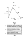
[0038] As novas funcionalidades que se acredita ser características das modalidades ilustrativas são definidas nas reivindicações anexas. As modalidades ilustrativas, no entanto, bem como um modo de uso preferido, objetivos e funcionalidades adicionais dos mesmos, serão mais bem entendidas por referência à seguinte descrição detalhada de uma modalidade ilustrativa da presente descrição quando lida em conjunto com os desenhos anexos, em que: a Figura 1 é uma ilustração de uma aeronave de acordo com uma modalidade ilustrativa pode ser implementada; a Figura 2 é uma ilustração de um diagrama de bloco de um ambiente de fabricação de acordo com uma modalidade ilustrativa; a Figura 3 é uma ilustração de uma vista de perspectiva de uma ferramenta de acordo com uma modalidade ilustrativa; a Figura 4 é uma ilustração de uma vista de seção transversal de uma estrutura dentro de uma ferramenta de acordo com uma modalidade ilustrativa; a Figura 5 é uma ilustração de uma vista de seção transversal de uma estrutura dentro de uma ferramenta de acordo com uma modalidade ilustrativa; a Figura 6 é uma ilustração de uma estrutura produzida de acordo com uma modalidade ilustrativa; a Figura 7 é uma ilustração de uma vista de perspectiva de uma ferramenta de acordo com outra modalidade ilustrativa; a Figura 8 é uma ilustração de uma vista de seção transversal de uma estrutura dentro de uma ferramenta de acordo com uma modalidade ilustrativa; a Figura 9 é uma ilustração de uma vista de seção transversal de uma estrutura dentro de uma ferramenta de acordo com uma modalidade ilustrativa; a Figura 10 é uma ilustração de uma vista de perspectiva de um mandril de acordo com uma modalidade ilustrativa; a Figura 11 é uma ilustração de um ciclo de temperatura de acordo com uma modalidade ilustrativa; a Figura 12 é uma ilustração de um fluxograma de um processo para formar uma estrutura de sanduíche de acordo com uma modalidade ilustrativa; a Figura 13 é uma ilustração de um fluxograma de um processo para formar uma estrutura de sanduíche de acordo com uma modalidade ilustrativa; a Figura 14 é uma ilustração de um método de fabricação e serviço de aeronave na forma de um diagrama de bloco de acordo com uma modalidade ilustrativa; e a Figura 15 é uma ilustração de uma aeronave na forma de um diagrama de bloco em que uma modalidade ilustrativa pode ser implementada.[0038] The new features that are believed to be characteristic of the illustrative modalities are defined in the attached claims. The illustrative modalities, however, as well as a preferred mode of use, objectives and additional functionalities thereof, will be better understood by reference to the following detailed description of an illustrative modality of the present description when read in conjunction with the accompanying drawings, in which : Figure 1 is an illustration of an aircraft according to an illustrative modality that can be implemented; Figure 2 is an illustration of a block diagram of a manufacturing environment according to an illustrative embodiment; Figure 3 is an illustration of a perspective view of a tool according to an illustrative embodiment; Figure 4 is an illustration of a cross-sectional view of a structure within a tool according to an illustrative embodiment; Figure 5 is an illustration of a cross-sectional view of a structure within a tool according to an illustrative embodiment; Figure 6 is an illustration of a structure produced according to an illustrative embodiment; Figure 7 is an illustration of a perspective view of a tool according to another illustrative embodiment; Figure 8 is an illustration of a cross-sectional view of a structure within a tool according to an illustrative embodiment; Figure 9 is an illustration of a cross-sectional view of a structure within a tool according to an illustrative embodiment; Figure 10 is an illustration of a perspective view of a mandrel according to an illustrative embodiment; Figure 11 is an illustration of a temperature cycle according to an illustrative embodiment; Figure 12 is an illustration of a flow chart of a process for forming a sandwich structure according to an illustrative embodiment; Figure 13 is an illustration of a flow chart of a process for forming a sandwich structure according to an illustrative embodiment; Figure 14 is an illustration of an aircraft manufacturing and service method in the form of a block diagram according to an illustrative embodiment; and Figure 15 is an illustration of an aircraft in the form of a block diagram in which an illustrative embodiment can be implemented.
[0039] A aeronave está sendo projetada e fabricada com mais e mais porcentagens de materiais compósitos. Materiais compósitos são usados na aeronave para diminuir o peso da aeronave. Este peso diminuído aprimora funcionalidades de desempenho tais como capacidade de carga e eficiência de combustível. Adicionalmente, materiais compósitos proveem vida de serviço mais longa para vários componentes em uma aeronave.[0039] The aircraft is being designed and manufactured with more and more percentages of composite materials. Composite materials are used on the aircraft to decrease the weight of the aircraft. This reduced weight improves performance features such as load capacity and fuel efficiency. In addition, composite materials provide longer service life for various components on an aircraft.
[0040] As diferentes modalidades ilustrativas reconhecem e levam em conta um número de diferentes considerações. Por exemplo, as modalidades ilustrativas reconhecem que o uso de painéis de sanduíche pode permitir a eliminação de colunas, longarinas, armações, ou outras estruturas de suporte no projeto de aeronave.[0040] The different illustrative modalities recognize and take into account a number of different considerations. For example, the illustrative modalities recognize that the use of sandwich panels can allow the elimination of columns, stringers, frames, or other support structures in aircraft design.
[0041] Os exemplos ilustrativos também reconhecem e levam em conta que estruturas de sanduíche compósitas atualmente implementadas podem ser criadas usando materiais termofixos. Uma estrutura de sanduíche compósita compreende uma estrutura tendo uma pluralidade de camadas de material. Em uma estrutura de sanduíche compósita, uma ou mais da pluralidade de camadas de material pode ser compósita de ou parcialmente compósita de materiais compósitos. Uma estrutura de sanduíche compósita pode ter uma pluralidade de cavidades se estendendo na estrutura. As modalidades ilustrativas reconhecem e levam em conta que o tempo necessário para criar uma estrutura de sanduíche a partir de materiais termofixos pode ser indesejável.[0041] The illustrative examples also recognize and take into account that currently implemented composite sandwich structures can be created using thermoset materials. A composite sandwich structure comprises a structure having a plurality of layers of material. In a composite sandwich structure, one or more of the plurality of layers of material may be composed of or partially composed of composite materials. A composite sandwich structure can have a plurality of cavities extending in the structure. The illustrative modalities recognize and take into account that the time required to create a sandwich structure from thermoset materials may be undesirable.
[0042] Por exemplo, materiais termofixos podem ser depositados à mão ou por máquina para formar a forma da estrutura de sanduíche. As modalidades ilustrativas reconhecem e levam em conta que a velocidade de deposição de material compósito pode ser limitada.[0042] For example, thermoset materials can be deposited by hand or by machine to form the shape of the sandwich structure. The illustrative modalities recognize and take into account that the speed of deposition of composite material can be limited.
[0043] Adicionalmente, as modalidades ilustrativas reconhecem e levam em conta que a cura de um material termofixo pode precisar de várias horas. Em adição à retenção do material termofixo em uma temperatura de cura por várias horas, autoclaves convencionais usando aquecimento resistivo para curar materiais termofixos pode precisar adicionalmente de várias horas para o aquecimento e a refrigeração.[0043] Additionally, the illustrative modalities recognize and take into account that the curing of a thermoset material may need several hours. In addition to retaining the thermoset material at a curing temperature for several hours, conventional autoclaves using resistive heating to cure thermoset materials may additionally require several hours for heating and cooling.
[0044] As diferentes modalidades ilustrativas reconhecem e levam em conta que a consolidação de um material termoplástico pode tomar significativamente menos tempo do que a cura de um material termofixo. Adicionalmente, as diferentes modalidades ilustrativas reconhecem e levam em conta que usando aquecimento indutivo podem reduzir o tempo necessário para consolidar um material termoplástico ou curar um material termofixo. Ainda adicionalmente, as diferentes modalidades ilustrativas reconhecem e levam em conta que usando aquecimento indutivo pode reduzir a energia consumida para consolidar um material termoplástico ou curar um material termofixo.[0044] The different illustrative modalities recognize and take into account that the consolidation of a thermoplastic material can take significantly less time than the curing of a thermoset material. In addition, the different illustrative modalities recognize and take into account that using inductive heating they can reduce the time needed to consolidate a thermoplastic material or cure a thermoset material. In addition, the different illustrative modalities recognize and take into account that using inductive heating can reduce the energy consumed to consolidate a thermoplastic material or cure a thermoset material.
[0045] As diferentes modalidades ilustrativas reconhecem e levam em conta que reduzir o tempo para formar uma parte pode aumentar o número de partes produzidas em uma ferramenta. Adicionalmente, as diferentes modalidades ilustrativas reconhecem e levam em conta que reduzir a energia consumida para formar uma parte pode reduzir o custo da parte.[0045] The different illustrative modalities recognize and take into account that reducing the time to form a part can increase the number of parts produced in a tool. In addition, the different illustrative modalities recognize and take into account that reducing the energy consumed to form a part can reduce the cost of the part.
[0046] As diferentes modalidades ilustrativas reconhecem e levam em conta que atualmente, estruturas de sanduíche termoplásticas podem ser produzidas usando fixadores. As diferentes modalidades ilustrativas reconhecem e levam em conta que produzir uma estrutura de sanduíche termoplástica sem fixadores pode reduzir o tempo necessário para produzir uma estrutura de sanduíche termoplástica. As diferentes modalidades ilustrativas reconhecem e levam em conta que produzir uma estrutura de sanduíche termoplástica sem fixadores pode reduzir o peso de uma estrutura de sanduíche termoplástica resultante.[0046] The different illustrative modalities recognize and take into account that currently, thermoplastic sandwich structures can be produced using fasteners. The different illustrative modalities recognize and take into account that producing a thermoplastic sandwich structure without fasteners can reduce the time required to produce a thermoplastic sandwich structure. The different illustrative modalities recognize and take into account that producing a thermoplastic sandwich structure without fasteners can reduce the weight of a resulting thermoplastic sandwich structure.
[0047] As diferentes modalidades ilustrativas também reconhecem e levam em conta que compósitos trançados podem prover propriedades aprimoradas sobre camadas empilhadas de estopas ou fita compósitas. Por exemplo, as modalidades ilustrativas reconhecem e levam em conta que compósitos trançados podem prover carregamento fora do plano aprimorado. Compósitos trançados podem compreender fibras que se cruzam, aprimorando o carregamento fora do plano sobre camadas compósitas empilhadas. Como usado aqui, “cargas fora do plano” se referem às cargas que não estão no plano do objeto. Por exemplo, cargas perpendiculares com a superfície de um compósito trançado são cargas fora do plano. Carregamento fora do plano aprimorado pode resultar em tolerância a danos aprimorada. Como usado aqui, tolerância a danos aprimorada quer dizer resistência aprimorada aos danos que resultam do impacto ou de outras fontes.[0047] The different illustrative modalities also recognize and take into account that woven composites can provide improved properties on stacked layers of tow or composite tape. For example, the illustrative modalities recognize and take into account that woven composites can provide loading outside the improved plane. Braided composites can comprise intersecting fibers, improving off-plane loading over stacked composite layers. As used here, "off-plane charges" refer to charges that are not on the object's plane. For example, loads perpendicular to the surface of a woven composite are off-plane loads. Loading outside the improved plane can result in improved damage tolerance. As used here, enhanced damage tolerance means improved resistance to damage that results from impact or other sources.
[0048] As diferentes modalidades ilustrativas também reconhecem e levam em conta que o uso de compósitos trançados pode reduzir tempo de fabricação de compósito. Por exemplo, as diferentes modalidades ilustrativas reconhecem e levam em conta que maquinário de trançamento pode usar um maior número de carretéis de material compósito de uma vez do que maquinário de posicionamento de compósito convencional. De maneira apropriada, as diferentes modalidades ilustrativas reconhecem que usar maquinário de trançamento pode reduzir o tempo de fabricação.[0048] The different illustrative modalities also recognize and take into account that the use of braided composites can reduce composite manufacturing time. For example, the different illustrative modalities recognize and take into account that braiding machinery can use a greater number of spools of composite material at one time than conventional composite positioning machinery. Appropriately, the different illustrative modalities recognize that using braiding machinery can reduce manufacturing time.
[0049] Com referência agora às figuras, e em particular, com referência à Figura 1, uma ilustração de uma aeronave é representada de acordo com uma modalidade ilustrativa. Neste exemplo ilustrativo, a aeronave 100 possui a asa 102 e a asa 104 anexada com o corpo 106. A aeronave 100 inclui o motor 108 anexado com a asa 102 e o motor 110 anexado com a asa 104.[0049] With reference now to the figures, and in particular, with reference to Figure 1, an illustration of an aircraft is represented according to an illustrative modality. In this illustrative example,
[0050] O corpo 106 possui a seção de cauda 112. Estabilizante horizontal 114, estabilizante horizontal 116, e estabilizante vertical 118 são anexados com a seção de cauda 112 do corpo 106.[0050]
[0051] A aeronave 100 é um exemplo de uma aeronave em que estruturas de sanduíche termoplásticas podem ser implementadas de acordo com uma modalidade ilustrativa. Em uma modalidade ilustrativa, um painel de revestimento da asa 104 pode compreender uma estrutura de sanduíche termoplástica. Em outra modalidade ilustrativa, porções do corpo 106 podem compreender uma estrutura de sanduíche termoplástica.[0051] The
[0052] A ilustração da aeronave 100 na Figura 1 não deve implicar limitações físicas ou de arquitetura à maneira em que uma configuração ilustrativa pode ser implementada. Por exemplo, apesar de a aeronave 100 ser uma aeronave comercial, a aeronave 100 pode ser uma aeronave militar, uma aeronave de rotor, um helicóptero, um veículo aéreo não tripulado, ou qualquer outra aeronave adequada.[0052] The illustration of
[0053] Apesar de os exemplos ilustrativos para uma modalidade ilustrativa serem descritos com relação a uma aeronave, uma modalidade ilustrativa pode ser aplicada a outros tipos de plataformas. A plataforma pode ser, por exemplo, uma plataforma móvel, uma plataforma estacionária, uma estrutura com base em terra, uma estrutura com base em água, e uma estrutura com base no espaço. Mais especificamente, a plataforma pode ser uma embarcação de superfície, um tanque, um porta aviões, um trem, uma nave espacial, uma estação espacial, um satélite, um submarino, um automóvel, uma usina de energia, uma ponte, uma represa, uma casa, um moinho de vento, uma instalação de fabricação, uma edificação, e outras plataformas adequadas.[0053] Although the illustrative examples for an illustrative modality are described in relation to an aircraft, an illustrative modality can be applied to other types of platforms. The platform can be, for example, a mobile platform, a stationary platform, a land-based structure, a water-based structure, and a space-based structure. More specifically, the platform can be a surface vessel, a tank, an aircraft carrier, a train, a spaceship, a space station, a satellite, a submarine, an automobile, a power plant, a bridge, a dam, a house, a windmill, a manufacturing facility, a building, and other suitable platforms.
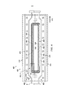
[0054] Com referência agora à Figura 2, uma ilustração de um diagrama de bloco de um ambiente de fabricação é representada de acordo com uma modalidade ilustrativa. Neste exemplo ilustrativo, o ambiente de fabricação 200 na Figura 2 é representado em uma forma de bloco para ilustrar diferentes componentes para uma ou mais modalidades ilustrativas. Neste exemplo representado, o ambiente de fabricação 200 inclui a ferramenta 202, a estrutura 206, a bexiga metálica 208, o controlador 210, a fonte de energia 212, a fonte de refrigerante 214, e o sensor 216.[0054] With reference now to Figure 2, an illustration of a block diagram of a manufacturing environment is represented according to an illustrative modality. In this illustrative example, the
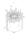
[0055] A ferramenta 202 está configurada para consolidar a estrutura 206. Como usado aqui, a consolidação compreende aplicar temperatura elevada, pressão elevada, ou temperatura elevada e pressão para um material termoplástico tal que a resina no material termoplástico escoa. Como a resina no material termoplástico escoa, as fibras de reforço podem ficar substancialmente na mesma orientação. Como a resina escoa pode minguar com a resina de materiais termoplásticos próximos nos limites dos materiais termoplásticos próximos. A resina solidifica com o resfriamento. A consolidação pode resultar em materiais compósitos com uma maior qualidade. Nos materiais compósitos, maior qualidade pode ser um maior volume de fibra com relação a todo o volume do material compósito. A consolidação pode resultar em materiais compósitos com um menor conteúdo de vazio. A ferramenta 202 compreende a pluralidade de restrições de carga 217 suportada pela pluralidade de suportes 251. A ferramenta também compreende a pluralidade de matrizes 218 localizada dentro da pluralidade de restrições de carga 217. A cavidade de matriz 220 pode ser um espaço criado pela pluralidade de matrizes 218. A cavidade de matriz 220 pode ser configurada para conter a estrutura 206 durante um processo de consolidação.[0055]
[0056] A pluralidade de matrizes 218 pode ser formada de um material que não é susceptível a aquecimento indutivo. Em alguns exemplos ilustrativos, a pluralidade de matrizes 218 pode ser formada a partir de um material cerâmico, compósito, fenólico ou algum outro material desejável. Em um exemplo ilustrativo, o material para a pluralidade de matrizes 218 pode ser selecionado com base em um coeficiente de expansão térmica, resistência ao choque térmico, e resistência à compressão. Neste exemplo ilustrativo, o material pode ser selecionado para ter um baixo coeficiente de expansão térmica, resistência ao choque térmico desejável, e resistência à compressão relativamente alta. Em um exemplo ilustrativo, a pluralidade de matrizes 218 pode ser uma cerâmica de sílica fundida que pode ser moldada.[0056] The plurality of
[0057] Como representado, a pluralidade de matrizes 218 contém pluralidade de bobinas de indução 222 e pluralidade de hastes 224. A pluralidade de bobinas de indução 222 possui as seções 223 e seções flexíveis 225. As seções 223 da pluralidade de bobinas de indução 222 podem ser incorporadas em pluralidade de matrizes 218. Em alguns exemplos ilustrativos, as seções 223 podem se estender ao longo do comprimento de cada matriz da pluralidade de matrizes 218. As seções flexíveis 225 da pluralidade de bobinas de indução 222 podem unir as seções 223 de diferentes matrizes na pluralidade de matrizes 218. Em um exemplo ilustrativo, as seções flexíveis 225 podem ter a flexibilidade adequada para mover quando a pluralidade de matrizes 218 se move. Em um exemplo ilustrativo, as seções flexíveis 225 podem ter a flexibilidade adequada para se mover para conectar seções 223. A pluralidade de bobinas de indução 222 pode ser conectada com o controlador 210, a fonte de energia 212, a fonte de refrigerante 214, e o sensor 216 através dos conectores 253 anexados com as seções flexíveis 225.[0057] As shown, the plurality of
[0058] O controlador 210 pode ser configurado para controlar a energia de entrada alimentada para a pluralidade de bobinas de indução 222 pela fonte de energia 212. Controlando a energia de entrada, o controlador 210 pode controlar o campo magnético produzido pelas bobinas de indução 222. Controlando o campo magnético produzido pelas bobinas de indução 222, o controlador 210 pode controlar a temperatura de operação da ferramenta 202.[0058]
[0059] O controlador 210 pode ser implementado em software, hardware, firmware ou uma combinação dos mesmos. Quando software é usado, as operações realizadas pelo controlador 210 podem ser implementadas em código de programa configurado para rodar em uma unidade de processador. Quando firmware é usado, as operações realizadas pelo controlador 210 podem ser implementadas em código de programa e dados e armazenada em memória persistente para rodar em uma unidade de processador. Quando hardware é empregado, o hardware pode incluir circuitos que operam para realizar as operações no controlador 210.[0059]
[0060] A fonte de refrigerante 214 pode ser configurada para fornecer refrigerante para a pluralidade de bobinas de indução 222. Refrigerante que escoa através da pluralidade de bobinas de indução 222 pode funcionar como um trocador de calor para transferir calor da ferramenta 202. O sensor 216 pode ser configurado para medir uma temperatura de uma porção da ferramenta 202 durante a operação.[0060]
[0061] A pluralidade de hastes 224 pode ser incorporada dentro da pluralidade de matrizes 218. A pluralidade de hastes 224 pode prover reforço para a pluralidade de matrizes 218. Em um exemplo ilustrativo, a pluralidade de hastes 224 é formada a partir de fibra de vidro. A pluralidade de hastes 224 pode ser mantida no lugar por uma pluralidade de cavilhas 227. Em alguns exemplos ilustrativos, a pluralidade de hastes 224 pode se estender de maneira longitudinal através de uma matriz na pluralidade de matrizes 218. Em alguns exemplos ilustrativos, a pluralidade de hastes 224 pode se estender de maneira transversal através de uma matriz na pluralidade de matrizes 218. Em alguns exemplos ilustrativos, a pluralidade de hastes 224 pode se estender tanto de maneira longitudinal quanto de maneira transversal através de uma matriz na pluralidade de matrizes 218.[0061] The plurality of
[0062] A cavidade de matriz 220 está associada com a fonte de gás inerte 215. Durante a consolidação de estrutura 206, gás inerte 221 pode estar presente na cavidade de matriz 220 a partir da fonte de gás inerte 215. Em alguns exemplos ilustrativos, a fonte de gás inerte 215 pode fornecer gás inerte para pressurizar a bexiga metálica 208.[0062] The
[0063] O número de revestimentos internos de matriz 226 está posicionado dentro da cavidade de matriz 220. Como representado, o número de revestimentos internos de matriz 226 compreende o material 229. O material 229 pode ser um material configurado para gerar calor quando exposto a um campo magnético. O material 229 pode ser selecionado a partir de um metal, uma liga de metal, um material cerâmico, um filme metalizado, ou qualquer outro material adequado. Em alguns exemplos ilustrativos, o número de revestimentos internos de matriz 226 compreende uma liga de metal tendo propriedades ferromagnéticas. Em alguns exemplos ilustrativos, um material ferromagnético para o número de revestimentos internos de matriz 226 pode ser selecionado com base em uma temperatura de consolidação desejada. Por exemplo, o material para número de revestimentos internos de matriz 226 pode ser selecionado com base em uma temperatura em que um material ferromagnético se toma não magnético. Esta temperatura também é conhecida como uma temperatura de Curie. Um material ferromagnético pode ser selecionado para número de revestimentos internos de matriz 226 tal que a temperatura de Curie para o material ferromagnético corresponde com uma temperatura de consolidação desejada. Nestes exemplos ilustrativos, o número de revestimentos internos de matriz 226 também pode ser referido como um número de susceptores inteligentes.[0063] The number of
[0064] O número de revestimentos internos de matriz 226 pode gerar calor quando exposto a um campo magnético gerado pela pluralidade de bobinas de indução 222. O número de revestimentos internos de matriz 226 pode ser usado para aplicar calor para a estrutura 206 durante um processo de consolidação.[0064] The number of
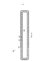
[0065] A estrutura 206 possui a seção transversal 228. A seção transversal 228 é a seção transversal fechada 233. Como usado aqui, uma seção transversal fechada é uma para a qual uma estrutura forma um trajeto fechado. De maneira apropriada, a estrutura 206 possui a seção transversal fechada 233 quando a seção transversal 228 da estrutura 206 forma um trajeto fechado. A seção transversal fechada 233 pode ser retangular 230, circular 232, ou triangular 234.[0065]
[0066] A estrutura 206 compreende a primeira camada termoplástica 236, a camada de núcleo termoplástico 238, e a segunda camada termoplástica 240. A estrutura 206 também pode ser referida como uma estrutura compósita. Antes da consolidação, a estrutura 206 pode ser referida como uma estrutura de pré-forma. Seguindo a consolidação, a estrutura 206 pode ser referida como uma estrutura consolidada.[0066]
[0067] A camada de núcleo termoplástico 238 compreende a pluralidade de partes de núcleo 237. A pluralidade de partes de núcleo 237 possui a pluralidade de cavidades 244 se estendendo para a camada de núcleo termoplástico 238. A pluralidade de cavidades 244 se estendendo para a estrutura 206 estão em comunicação com a pluralidade de aberturas 246 na superfície 242 da estrutura 206. A pluralidade de cavidades 244 pode se estender através da estrutura 206 na direção longitudinal 245. Em alguns exemplos ilustrativos, a pluralidade de cavidades 244 pode se estender através da estrutura 206 em uma direção substancialmente paralela ao primeiro lado 239 e ao segundo lado 241 da camada de núcleo termoplástico 238.[0067] The thermoplastic core layer 238 comprises the plurality of core parts 237. The plurality of core parts 237 has the plurality of
[0068] A camada de núcleo termoplástico 238 contém a pluralidade de mandris 248 dentro da pluralidade de cavidades 244. Em um exemplo ilustrativo, a estrutura 206 é a estrutura de sanduíche 247 e a pluralidade de mandris 248 é interna à estrutura de sanduíche 247.[0068] The thermoplastic core layer 238 contains the plurality of
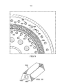
[0069] A pluralidade de mandris 248 compreende o segundo material 250 e o primeiro material 252. No exemplo ilustrativo, o segundo material 250 é um material solúvel. Em um exemplo ilustrativo, o segundo material 250 pode ser solúvel em água. Neste exemplo ilustrativo, o segundo material 250 pode ser selecionado a partir de pelo menos um de um material cerâmico, grafita ou outro material adequado que é solúvel em água. Como usado aqui, a frase “pelo menos um de”, quando usado com uma lista de itens, quer dizer diferentes combinações de um ou mais dos itens listados podem ser usados e apenas um de cada item na lista pode ser necessário. Por exemplo, “pelo menos um de item A, item B, e item C” pode incluir, sem limitação, item A ou item A e item B. este exemplo também pode incluir item A, item B, e item C ou item B e item C.[0069] The plurality of
[0070] O primeiro material 252 é um material configurado para gerar calor em resposta a um campo magnético. Em alguns exemplos ilustrativos, o primeiro material 252 compreende uma liga de metal tendo propriedades ferromagnéticas. Em alguns exemplos ilustrativos, um material ferromagnético para o primeiro material 252 pode ser selecionado com base em pelo menos um de uma temperatura de consolidação desejada e a temperatura de Curie do número de revestimentos internos de matriz 226. Por exemplo, o material para o primeiro material 252 pode ser selecionado com base em uma temperatura em que número de revestimentos internos de matriz 226 se toma não magnético. Um material ferromagnético pode ser selecionado para o primeiro material 252 tal que o primeiro material 252 gera calor após o número de revestimentos internos de matriz 226 se toma não magnético. Nestes exemplos ilustrativos, a pluralidade de tubos metálicos 254também pode ser referido como uma pluralidade de susceptores inteligentes. O primeiro material 252 pode ser selecionado a partir da liga 510, Invar, Kovar, Moly Permalloy, ou qualquer outro material adequado que gera calor quando exposto a um campo magnético. A liga 510 também pode ser conhecida como Phosphor Bronze. Em alguns exemplos ilustrativos, a pluralidade de tubos metálicos 254 pode ser formada de Invar. O primeiro material 252 pode ser selecionado com base em pelo menos um de uma temperatura de consolidação desejada e a temperatura de Curie do número 252 pode ser Invar quando a temperatura de Curie de Invar é desejável levando em conta a temperatura de consolidação desejada e a temperatura de Curie do número de revestimentos internos de matriz. Invar pode ser selecionado como o primeiro material 252 com base em outras propriedades de Invar. Especificamente, o coeficiente de expansão térmica de Invar pode ser desejável para o uso no processamento de material compósito. O coeficiente de expansão térmica de Invar pode ser substancialmente similar ao coeficiente de expansão térmica de material compósito.[0070] The
[0071] Em alguns exemplos ilustrativos, o primeiro material 252 pode ser incorporado dentro de segundo material 250 na pluralidade de mandris 248. Em um exemplo ilustrativo, o primeiro material 252 pode tomar a forma de uma pluralidade de tubos metálicos 254 dentro de segundo material 250.[0071] In some illustrative examples, the
[0072] A primeira camada termoplástica 236 possui a seção transversal fechada 235. Em alguns exemplos ilustrativos, a seção transversal fechada 235 pode ter substancialmente a mesma forma que a seção transversal fechada 233 da estrutura 206.[0072] The first thermoplastic layer 236 has closed
[0073] A primeira camada termoplástica 236, a camada de núcleo termoplástico 238, e a segunda camada termoplástica 240 pode ser consolidada em conjunto. Como usado aqui, um material é consolidado quando o material é exposto a pelo menos um de calor e pressão de forma que o material escoa e solidifica. Como usado aqui, materiais podem ser consolidados em conjunto quando os materiais são expostos juntos a pelo menos um de calor e pressão de forma que os materiais escoam e solidificam. A consolidação conjunta da primeira camada termoplástica 236 e da camada de núcleo termoplástico 238 pode criar uma interface onde a resina da primeira camada termoplástica 236 e a resina da camada de núcleo termoplástico 238 podem escoar juntas. Da mesma forma, a consolidação conjunta da segunda camada termoplástica 240 e a camada de núcleo termoplástico 238 pode criar uma interface onde a resina da segunda camada termoplástica 240 e a resina da camada de núcleo termoplástico 238 podem escoar juntas.[0073] The first thermoplastic layer 236, the thermoplastic core layer 238, and the
[0074] Em alguns exemplos ilustrativos, a primeira camada termoplástica 236 pode ser consolidada contra o primeiro lado 239 da camada de núcleo termoplástico 238. Em um exemplo ilustrativo, o primeiro lado 239 podem compreender uma superfície externa da camada de núcleo termoplástico 238. Em alguns exemplos ilustrativos, a segunda camada termoplástica 240 pode ser consolidada contra o segundo lado 241 da camada de núcleo termoplástico 238. Em um exemplo ilustrativo, o segundo lado 241 podem compreender uma superfície interna da camada de núcleo termoplástico 238.[0074] In some illustrative examples, the first thermoplastic layer 236 can be consolidated against the
[0075] A bexiga metálica 208 pode ser associada com a segunda camada termoplástica 240. Em alguns exemplos ilustrativos, a bexiga metálica 208 pode ser posicionada dentro da segunda camada termoplástica 240. Em alguns exemplos ilustrativos, a segunda camada termoplástica 240 pode ser posicionada na bexiga metálica 208. Em alguns exemplos ilustrativos, a bexiga metálica 208 pode funcionar como um mandril. Durante a consolidação, a bexiga metálica 208 pode ser pressurizada tal que a bexiga metálica 208 transmite uma força compressiva. Em alguns exemplos ilustrativos, a bexiga metálica 208 pode ser pressurizada usando um gás inerte.[0075] The
[0076] Quando a estrutura 206 é um material termoplástico trançado, fendas de material termoplástico trançado podem se mover uma com relação à outra. Este movimento de material termoplástico trançado pode ocorrer quando a bexiga metálica 208 se expande sob pressão. O movimento de material termoplástico trançado pode aprimorar a qualidade de estrutura resultante 206.[0076] When
[0077] A bexiga metálica 208 pode ser formada a partir de um material que exibe características desejáveis 243. As características desejáveis 243 para a bexiga metálica 208 pode incluir uma capacidade de reter características de pressão, estabilidade térmica, flexibilidade, conformidade, e expansão térmica. Por exemplo, pode ser desejável que o material da bexiga metálica 208 para ser termicamente estável nas temperaturas de consolidação para a estrutura 206.[0077] The
[0078] Adicionalmente, pode ser desejável que o material da bexiga metálica 208 seja flexível para prover uma distribuição de pressão igual. Adicionalmente, pode ser desejável que o material da bexiga metálica 208 pode ser conformado para quedas de lona ou outra topografia da estrutura 206. Ainda adicionalmente, pode ser desejável que o material da bexiga metálica 208 tenha características de expansão térmica para permitir a remoção da bexiga metálica 208 seguindo a consolidação.[0078] Additionally, it may be desirable for the material of the
[0079] Em alguns exemplos ilustrativos, o número de bexigas metálicas 208 pode ser formada de materiais tendo propriedades magnéticas. Em alguns destes exemplos ilustrativos, o número de bexigas metálicas 208 pode gerar calor quando exposto a um campo magnético. Em alguns exemplos ilustrativos, o número de bexigas metálicas 208 pode ser formado de um material não magnético.[0079] In some illustrative examples, the number of
[0080] Em alguns exemplos ilustrativos, a bexiga metálica 208 pode ser formada de alumínio ou uma liga de alumínio. Em alguns exemplos ilustrativos, a bexiga metálica 208 pode ser formada de magnésio ou uma liga de magnésio. Em outros exemplos ilustrativos, outros materiais metálicos diferentes do que alumínio ou magnésio podem prover características desejáveis 243 tais como uma capacidade de reter características de pressão, estabilidade térmica, flexibilidade, conformidade, e expansão térmica.[0080] In some illustrative examples, the
[0081] A bexiga metálica 208 está associada com a fonte de pressão 217. A fonte de pressão 217 é configurada para pressurizar a bexiga metálica 208 durante a consolidação de estrutura 206 na ferramenta 202.[0081]
[0082] A ilustração do ambiente de fabricação 200 na Figura 2 não deve implicar limitações físicas ou de arquitetura à maneira em que uma modalidade ilustrativa pode ser implementada. Outros componentes em adição a ou no lugar daqueles ilustrados podem ser usados. Alguns componentes podem ser desnecessários. Ainda, os blocos são apresentados para ilustrar alguns componentes funcionais. Um ou mais destes blocos podem ser combinados, divididos, ou combinados e divididos em diferentes blocos quando implementados em uma modalidade ilustrativa.[0082] The illustration of the
[0083] Por exemplo, a pluralidade de hastes 224 em vez disso pode ser formada de um material diferente do que fibra de vidro. Neste exemplo, uma pluralidade de hastes de reforço pode ser formada de um material que preferivelmente não é eletricamente condutor. Em outro exemplo, a pluralidade de hastes de reforço pode ser formada de um material eletricamente condutor e arranjado tal que eles não são susceptíveis ao aquecimento por indução.[0083] For example, the plurality of
[0084] Como outro exemplo, em vez de material termoplástico da primeira camada termoplástica 236, a camada de núcleo termoplástico 238, e a segunda camada termoplástica 240, a estrutura 206 podem compreender um material termofixo. Apesar de a ferramenta 202 ser descrita acima como realizando um processo de consolidação, neste exemplo ilustrativo, a ferramenta 202 pode ser usada para realizar um processo de cura do material termofixo. A cura de um material termofixo pode ser realizada em uma menor temperatura do que a consolidação de um material termoplástico. Como um resultado, nestes exemplos ilustrativos, o número de bexigas metálicas 208 pode compreender um material elastomérico em vez do que um material metálico.[0084] As another example, instead of the thermoplastic material of the first thermoplastic layer 236, the thermoplastic core layer 238, and the
[0085] Como mais um exemplo, a seção transversal 228 pode ser uma seção transversal aberta ou uma seção transversal substancialmente fechada. Por exemplo, a seção transversal 228 pode ser uma forma em V, forma em I, forma em J, forma em Z, forma em T, forma em C, forma em U, ou outra forma adequada.[0085] As yet another example,
[0086] Se voltando agora à Figura 3, uma ilustração de uma vista de perspectiva de uma ferramenta é representada de acordo com uma modalidade ilustrativa. Neste exemplo representado, a ferramenta 300 é um exemplo de uma implementação física para a ferramenta 202 e componentes na ferramenta 202 na Figura 2.[0086] Turning now to Figure 3, an illustration of a perspective view of a tool is represented according to an illustrative modality. In this example shown,
[0087] Neste exemplo ilustrativo, a ferramenta 300 inclui primeira matriz 302 e a segunda matriz 304. A primeira matriz 302 e a segunda matriz 304 pode ser uma implementação física da pluralidade de matrizes 218 da Figura 2. Como representado, a primeira matriz 302 é montada dentro da restrição de carga 306 e a segunda matriz 304 é montada dentro da restrição de carga 308. A restrição de carga 306 e a restrição de carga 308 pode ser uma implementação física da pluralidade de restrições de carga 217 da Figura 2. A primeira matriz 302 e a segunda matriz 304 podem ser anexadas com a restrição de carga 306 e a restrição de carga 308, respectivamente, por qualquer dispositivo de fixação adequado tal como por cavilha ou grampo.[0087] In this illustrative example,
[0088] Como representado, a restrição de carga 306 e a restrição de carga 308 são montadas no suporte de coluna 310, no suporte de coluna 312, o suporte de coluna 314, e no suporte de coluna 316. O suporte de coluna 310, o suporte de coluna 312, o suporte de coluna 314, e o suporte de coluna 316 pode ser uma implementação física da pluralidade de suportes 251 da Figura 2. A restrição de carga 306 e a restrição de carga 308 proveem superfícies de apoio para a primeira matriz 302 e a segunda matriz 304. A restrição de carga 306 e a restrição de carga 308 pode evitar que a primeira matriz 302 e a segunda matriz 304 dobrem e rachem durante as operações de fabricação. A restrição de carga 306 e a restrição de carga 308 podem ser formadas a partir de aço, alumínio, ou qualquer outro material desejável. O material para a restrição de carga 306 e a restrição de carga 308 pode ser selecionado com base as cargas presentes durante a formação ou a consolidação. O material para a restrição de carga 306 e a restrição de carga 308 pode ser selecionado para prover características desejáveis tais como rigidez desejável e resistência desejável para evitar que a primeira matriz 302 e a segunda matriz 304 dobrem e/ou rachem durante as operações de fabricação. Em alguns exemplos ilustrativos, o material pode ser não magnético para reduzir qualquer distorção para o campo magnético produzido pela pluralidade de bobinas de indução 320. Em alguns exemplos ilustrativos, a restrição de carga 306 e a restrição de carga 308 pode não estar presente. Nestes exemplos ilustrativos, a primeira matriz 302 e a segunda matriz 304 pode ser forte o suficiente para evitar dobrar ou rachar a primeira matriz 302 e a segunda matriz 304 sem restrição de carga 306 e a restrição de carga 308.[0088] As shown, the
[0089] A primeira matriz 302 e a segunda matriz 304 são reforçadas com a pluralidade de hastes 318 que é mantida com a pluralidade de cavilhas 319. A pluralidade de hastes 318 pode ser uma implementação física da pluralidade de hastes 224 da Figura 2. A pluralidade de cavilhas 319 pode ser uma implementação física da pluralidade de cavilhas 227 da Figura 2. A pluralidade de hastes 318 se estende tanto de maneira longitudinal 321 e de maneira transversal 323 em uma grade através da primeira matriz 302 e da segunda matriz 304.[0089] The
[0090] A pluralidade de bobinas de indução 320 está associada com a primeira matriz 302 e a segunda matriz 304. A pluralidade de bobinas de indução 320 pode ser uma implementação física da pluralidade de bobinas de indução 222 da Figura 2. A pluralidade de bobinas de indução320 compreende seções 322 e seções flexíveis 324. Como representado, as seções 322 se estendem ao longo do comprimento da primeira matriz 302 e da segunda matriz 304. As seções 322 pode ser uma implementação física das seções 223 da Figura 2. As seções 322 podem ser incorporadas em primeira matriz 302 e a segunda matriz 304. As seções flexíveis 324 unem as seções 322 na primeira matriz 302 e na segunda matriz 304. As seções flexíveis 324 podem ser uma implementação física das seções flexíveis 225 da Figura 2. Os conectores 326 localizados nas extremidades da pluralidade de bobinas de indução 320 podem conectar a pluralidade de bobinas de indução 320 com um controlador, fonte de energia, fonte de refrigerante, ou outra utilidade externa. Os conectores 326 podem ser uma implementação física dos conectores 253 da Figura 2.[0090] The plurality of
[0091] A ilustração da ferramenta 300 na Figura 3não deve implicar limitações físicas ou de arquitetura à maneira em que uma modalidade ilustrativa pode ser implementada. Outros componentes em adição a ou no lugar daqueles ilustrados podem ser usados. Alguns componentes podem ser desnecessários.[0091] The illustration of
[0092] Por exemplo, a pluralidade de hastes 318 pode se estender em apenas uma direção dentro da primeira matriz 302 e a segunda matriz 304. Como outro exemplo, apesar de apenas a primeira matriz 302 e a segunda matriz 304 serem representadas, a ferramenta 300 em vez disso pode ter três ou mais matrizes.[0092] For example, the plurality of
[0093] Se voltando agora à Figura 4, uma ilustração de uma vista de seção transversal de uma estrutura dentro de uma ferramenta é representada de acordo com uma modalidade ilustrativa. A vista 400 pode ser uma vista de seção transversal de uma estrutura dentro da ferramenta 300 da Figura 3 a partir da direção 323 e corte 4-4. A ferramenta 402 pode ser uma implementação física da ferramenta 202 na Figura 2. A estrutura 404 pode ser uma implementação física da estrutura 206 na Figura 2.[0093] Turning now to Figure 4, an illustration of a cross-sectional view of a structure inside a tool is represented according to an illustrative modality. View 400 can be a cross-sectional view of a structure within
[0094] Como representado, a estrutura 404está posicionada dentro da ferramenta 402. Especificamente, a estrutura 404está posicionada entre primeira matriz 406 e a segunda matriz 408 dentro da cavidade de matriz 405 da ferramenta 402. A pluralidade de bobinas de indução 410 corre de maneira longitudinal 411 através da primeira matriz 406 e da segunda matriz 408. A pluralidade de bobinas de indução 410 são unidas pelas seções flexíveis 412. A pluralidade de hastes 413 corre através da primeira matriz 406. A pluralidade de hastes 415 corre através de segunda matriz 408. A primeira matriz 406 e a segunda matriz 408 são mantidas dentro da restrição de carga 414 e da restrição de carga 416.[0094] As shown,
[0095] O revestimento interno de matriz 418 está associado com a primeira matriz 406 dentro da cavidade de matriz 405. O revestimento interno de matriz 420 está associada com segunda matriz 408 na cavidade de matriz 405. O revestimento interno de matriz 418 e o revestimento interno de matriz 420 contatam a estrutura 404 dentro da cavidade de matriz 405.[0095] The
[0096] A estrutura 404 compreende a primeira camada termoplástica 422, a camada de núcleo termoplástico 424, e a segunda camada termoplástica 426. A primeira camada termoplástica 422 pode ser uma implementação física da primeira camada termoplástica 236 da Figura 2. A camada de núcleo termoplástico 424 pode ser uma implementação física da camada de núcleo termoplástico 238 da Figura 2. A segunda camada termoplástica 426 pode ser uma implementação física da segunda camada termoplástica 240 da Figura 2.[0096]
[0097] A segunda camada termoplástica 426 pode ser formada usando um processo de deposição de compósito. O processo de deposição de compósito pode ser selecionado a partir de um de trançamento, deposição de fita, deposição de estopa, ou qualquer outro processo de deposição de compósito desejado. Em alguns exemplos ilustrativos, a segunda camada termoplástica 426 pode ser posicionada na bexiga metálica 430 através de um processo de deposição de compósito. Em um exemplo ilustrativo, o processo de deposição de compósito pode depositar o material compósito diretamente na bexiga metálica 430. Em um exemplo ilustrativo, o material compósito trançado pode ser posicionado diretamente para a bexiga metálica 430 para formar a segunda camada termoplástica 426.[0097] The
[0098] Em alguns exemplos ilustrativos, a segunda camada termoplástica 426 pode ser posicionado na bexiga metálica 430 como uma pré-forma. Neste exemplo ilustrativo, a segunda camada termoplástica 426 pode ser formada para uma forma desejada antes de ser posicionada na bexiga metálica 430. Em alguns exemplos ilustrativos, a segunda camada termoplástica 426 pode ser consolidada ou semirrígida como a segunda camada termoplástica 426 é posicionada na bexiga metálica 430.[0098] In some illustrative examples, the
[0099] A camada de núcleo termoplástico 424 está posicionada adjacente à segunda camada termoplástica 426. A camada de núcleo termoplástico 424 possui a pluralidade de cavidades 427. A pluralidade de cavidades 427 contém a pluralidade de mandris 428. A pluralidade de cavidades 427 se estendem para a Figura 4. Em outras palavras, a pluralidade de cavidades 427 se estende de maneira longitudinal através da estrutura 404.[0099] The
[00100] A camada de núcleo termoplástico 424 pode ser formada usando um processo de deposição de compósito. O processo de deposição de compósito pode ser selecionado a partir de um de trançamento, deposição de fita, deposição de estopa, ou outro processo de deposição de compósito desejável. Em alguns exemplos ilustrativos, a camada de núcleo termoplástico 424 pode ser formada depositando material compósito para a pluralidade de mandris 428. Em um exemplo ilustrativo, a camada de núcleo termoplástico 424 pode ser formada depositando um material termoplástico trançado sobre a pluralidade de mandris 428. Após depositar material compósito para a pluralidade de mandris 428, a pluralidade de mandris 428 pode ser posicionada um com relação ao outro para formar a camada de núcleo termoplástico 424. Em um exemplo ilustrativo, a pluralidade de mandris 428 pode ser posicionada um com relação ao outro na segunda camada termoplástica 426.[00100] The
[00101] A primeira camada termoplástica 422 pode ser formada de um número de camadas de fita compósita, estopas compósitas, um compósito trançado, ou qualquer outro material adequado compósito. A primeira camada termoplástica 422 pode ser formada usando um processo de deposição de compósito. O processo de deposição de compósito pode ser selecionado a partir de um de trançamento, deposição de fita, deposição de estopa, ou qualquer outro processo de deposição de compósito desejável. Em alguns exemplos ilustrativos, a primeira camada termoplástica 422 pode ser posicionada na camada de núcleo termoplástico 424 através de um processo de deposição de compósito. Em um exemplo ilustrativo, o processo de deposição de compósito pode depositar material compósito diretamente para a camada de núcleo termoplástico 424. Em um exemplo ilustrativo, o material compósito trançado pode ser depositado diretamente para a camada de núcleo termoplástico 424 para formar primeira camada termoplástica 422.[00101] The
[00102] Em alguns exemplos ilustrativos, a primeira camada termoplástica 422 pode ser posicionada na camada de núcleo termoplástico 424 como uma pré-forma. Como usado aqui, uma pré-forma é um material compósito formado para uma forma desejada antes de ser posicionado em uma localização. Neste exemplo ilustrativo, a primeira camada termoplástica 422 pode ser formada para uma forma desejada antes de ser posicionada na camada de núcleo termoplástico 424. Em alguns exemplos ilustrativos, a primeira camada termoplástica 422 pode ser consolidada ou semirrígida como a primeira camada termoplástica 422 está posicionada na camada de núcleo termoplástico 424.[00102] In some illustrative examples, the
[00103] Para consolidar a estrutura 404, energia pode ser fornecida para pluralidade de bobinas de indução 410 para produzir um campo magnético. Em resposta ao campo magnético, o revestimento interno de matriz 418 e o revestimento interno de matriz 420 podem gerar calor.[00103] To consolidate
[00104] A bexiga metálica 430 pode ser pressurizada. A bexiga metálica 430 está posicionada dentro da estrutura 404 tal que a bexiga metálica 430 contata a segunda camada termoplástica 426 dentro da estrutura 404.[00104] The
[00105] Quando pressurizada, a bexiga metálica 430 pode transmitir uma força compressiva para a estrutura 404. A bexiga metálica 430 pode transmitir uma força compressiva para a estrutura 404 expandindo sob pressão para a estrutura de prensa 404 contra o revestimento interno de matriz 418 e o revestimento interno de matriz 420. O revestimento interno de matriz 418 e o revestimento interno de matriz 420 são associados com a primeira matriz 406 e a segunda matriz 408. A primeira matriz 406 e a segunda matriz 408 definem uma linha de molde externo para a estrutura 404. Quando a bexiga metálica 430 é pressurizada, a primeira matriz 406 e a segunda matriz 408 proveem pressão resistente. Em outras palavras, a primeira matriz 406 e a segunda matriz 408 podem prover uma linha de molde externo substancialmente rígida para a estrutura 404. Efetivamente a bexiga metálica 430 se expande e pressiona a estrutura 404 contra a primeira matriz 406 e a segunda matriz 408.[00105] When pressurized, the
[00106] Quando a estrutura 404 é um material termoplástico trançado, fendas de material termoplástico trançado podem se mover uma em relação à outra. Este movimento de material termoplástico trançado pode ocorrer quando bexiga metálica 430 se expande sob pressão. O movimento de material termoplástico trançado pode aprimorar a qualidade de estrutura resultante 404.[00106] When the 404 structure is a braided thermoplastic material, slits of braided thermoplastic material can move in relation to each other. This movement of braided thermoplastic material can occur when the
[00107] A pluralidade de mandris 428 pode evitar ou reduzir alterações indesejáveis para a forma da camada de núcleo termoplástico 424 durante a consolidação. Em outras palavras, pressão aplicada pela bexiga metálica 430 pode não esmagar ou impactar de maneira desejável a pluralidade de cavidades 427 devido à pluralidade de mandris 428 dentro da pluralidade de cavidades 427.[00107] The plurality of
[00108] Como a estrutura 404 é aquecida e comprimida, a primeira camada termoplástica 422 é consolidada contra camada de núcleo termoplástico 424. Durante o aquecimento e a compressão, a resina da primeira camada termoplástica 422 escoa contra a camada de núcleo termoplástico 424. Quando a estrutura 404 é resfriada, a resina de primeira camada termoplástica 422 pode solidificar contra camada de núcleo termoplástico 424. A primeira camada termoplástica 422 e a camada de núcleo termoplástico 424 pode criar uma interface onde a resina da primeira camada termoplástica 422 e a resina da camada de núcleo termoplástico 424 podem escoar juntas.[00108] As the
[00109] Quando a estrutura 404 é aquecida e comprimida, a segunda camada termoplástica 426 é consolidada contra camada de núcleo termoplástico 424. Durante o aquecimento e a compressão, a resina da segunda camada termoplástica 426 escoa contra camada de núcleo termoplástico 424. Quando a estrutura 404 é resfriada, a resina da segunda camada termoplástica 426 pode solidificar contra camada de núcleo termoplástico 424. A segunda camada termoplástica 426 e a camada de núcleo termoplástico 424 pode criar uma interface onde a resina da segunda camada termoplástica 426 e a resina da camada de núcleo termoplástico 424 podem escoar juntas.[00109] When the
[00110] Se voltando agora à Figura 5, uma ilustração de uma vista de seção transversal de uma estrutura dentro de uma ferramenta é representada de acordo com uma modalidade ilustrativa. Figura 5 é uma vista da estrutura 404 dentro da caixa 5. A estrutura 404 pode ser pode ser uma implementação física da estrutura 206 na Figura 2.[00110] Turning now to Figure 5, an illustration of a cross-sectional view of a structure inside a tool is represented according to an illustrative modality. Figure 5 is a view of
[00111] Como representado na Figura 5, a pluralidade de mandris 428 está localizada dentro da pluralidade de cavidades 427 da camada de núcleo termoplástico 424. Como representado na Figura 4 e Figura 5, a pluralidade de mandris 428 compreende mais do que uma forma de seção transversal. O mandril 502, o mandril 504, e o mandril 506 estão dentro da pluralidade de mandris 428. O mandril 502 possui uma seção transversal circular. Cada um do mandril 504 e do mandril 506 possui uma seção transversal trapezoidal. Em alguns exemplos ilustrativos, a pluralidade de mandris 428 pode ter formas de seção transversal diferentes ou adicionais.[00111] As shown in Figure 5, the plurality of
[00112] O mandril 502, o mandril 504, e o mandril 506 pode atuar como a formação de ferramentas para a camada de núcleo termoplástico 424. Durante a formação da camada de núcleo termoplástico 424, o material compósito pode ser depositado para mandril 502, o mandril 504, e o mandril 506 para formar três partes de núcleo. Após depositar material compósito, o mandril 502, o mandril 504, e o mandril 506 podem ser posicionados um com relação ao outro para formar uma porção da camada de núcleo termoplástico 424. Em um exemplo ilustrativo, o material compósito trançado pode ser depositado para o mandril 502, o mandril 504, e o mandril 506.[00112]
[00113] O mandril 502 está configurado para prover resistência à pressão a partir da bexiga metálica 430 durante um processo de consolidação. Como um resultado, o mandril 502 mantém ou substancialmente mantém a forma da cavidade 503 da pluralidade de cavidades 427 durante a consolidação. O mandril 502 compreende o segundo material 508 formado para uma forma de seção transversal circular e o primeiro material 510 formado para um tubo.[00113]
[00114] O segundo material 508 compreende um material solúvel. O primeiro material 510 compreende um material configurado para gerar calor em resposta a um campo magnético. Em alguns exemplos ilustrativos, o primeiro material 510 é Invar.[00114] The
[00115] O primeiro material 510 pode ser selecionado com base em pelo menos um de uma temperatura de consolidação desejada e a temperatura de Curie do número de revestimentos internos de matriz a ser usado. Como um resultado, o primeiro material 510 pode ser Invar quando a temperatura de Curie de Invar é desejável levando em conta a temperatura de consolidação desejada e a temperatura de Curie do número de revestimentos internos de matriz. Invar pode ser selecionado como primeiro material 510 com base em outras propriedades de Invar. Especificamente, o coeficiente de expansão térmica de Invar pode ser desejável para o uso no processamento de material compósito. O coeficiente de expansão térmica de Invar pode ser substancialmente similar ao coeficiente de expansão térmica de material compósito.[00115] The
[00116] O primeiro material 510 podem prover reforço para o segundo material 508. Em algumas modalidades ilustrativas, o primeiro material 510 pode aumentar a rigidez do mandril 502.[00116] The
[00117] Durante a consolidação de estrutura 404, o primeiro material 510 pode gerar calor em resposta a um campo magnético gerado pela pluralidade de bobinas de indução 410. Em alguns exemplos ilustrativos, o primeiro material 510 pode gerar calor após o aquecimento do revestimento interno de matriz 418 e o revestimento interno de matriz 420 prossegue até o revestimento interno de matriz 418 e o revestimento interno de matriz 420 serem quase não magnéticos.[00117] During consolidation of
[00118] O mandril 504 está configurado para prover resistência à pressão a partir da bexiga metálica 430 durante um processo de consolidação. Como um resultado, o mandril 504 mantém ou substancialmente mantém a forma da cavidade 505 da pluralidade de cavidades 427 durante a consolidação. O mandril 504 compreende segundo material 512 formado para uma forma de seção transversal trapezoidal e primeiro material 514 formado para um tubo.[00118]
[00119] O segundo material 512 compreende um material solúvel. O primeiro material 514 compreende um material configurado para gerar calor em resposta a um campo magnético. Em alguns exemplos ilustrativos, o primeiro material 514 é Invar. O primeiro material 514 podem prover reforço para o segundo material 512. Em algumas modalidades ilustrativas, o primeiro material 514 pode aumentar a rigidez do mandril 504.[00119] The
[00120] Durante a consolidação de estrutura 404, o primeiro material 514 pode gerar calor em resposta a um campo magnético gerado pela pluralidade de bobinas de indução 410. Em alguns exemplos ilustrativos, o primeiro material 514 pode gerar calor após o aquecimento do revestimento interno de matriz 418 e o revestimento interno de matriz 420 prossegue até o revestimento interno de matriz 418 e o revestimento interno de matriz 420 serem quase não magnéticos.[00120] During consolidation of
[00121] O mandril 506 está configurado para prover resistência à pressão a partir da bexiga metálica 430 durante um processo de consolidação. Como um resultado, o mandril 506 mantém ou substancialmente mantém a forma da cavidade 509 da pluralidade de cavidades 427 durante a consolidação. O mandril 506 compreende segundo material 516 formado para uma forma de seção transversal trapezoidal e primeiro material 518 formado para um tubo.[00121]
[00122] O segundo material 516 compreende um material solúvel. O primeiro material 518 compreende um material configurado para gerar calor em resposta a um campo magnético. Em alguns exemplos ilustrativos, o primeiro material 518 é Invar. O primeiro material 518 podem prover reforço para o segundo material 516. Em algumas modalidades ilustrativas, o primeiro material 518 pode aumentar a rigidez do mandril 506.[00122] The
[00123] Durante a consolidação de estrutura 404, o primeiro material 518 pode gerar calor em resposta a um campo magnético gerado pela pluralidade de bobinas de indução 410. Em alguns exemplos ilustrativos, o primeiro material 518 pode gerar calor após o aquecimento do revestimento interno de matriz 418 e o revestimento interno de matriz 420 prossegue até o revestimento interno de matriz 418 e o revestimento interno de matriz 420 serem quase não magnéticos.[00123] During consolidation of
[00124] Seguindo a consolidação, o segundo material 508, o segundo material 512, e o segundo material 516 pode ser dissolvido. O primeiro material 510, o primeiro material 514, e primeiro material 518 então podem ser removidos da cavidade 503, da cavidade 505, e da cavidade 509.[00124] Following consolidation, the
[00125] Se voltando agora à Figura 6, uma ilustração de uma vista frontal de uma estrutura produzida é representada de acordo com uma modalidade ilustrativa. A estrutura 600 pode ser uma modalidade física da estrutura 206 formada usando ferramenta 202 da Figura 2. A estrutura 600 pode ser uma modalidade física da estrutura 404a partir da direção 323 da Figura 3 seguindo a consolidação na ferramenta 402 e remoção da pluralidade de mandris 428 a partir da pluralidade de cavidades 427. A estrutura 600 pode ser um painel de revestimento para a asa 104 da aeronave 100 da Figura 1.[00125] Turning now to Figure 6, an illustration of a front view of a structure produced is represented according to an illustrative modality.
[00126] A estrutura 600 é uma estrutura de sanduíche termoplástica consolidada. A estrutura 600 como mostrada se estende para a página. A estrutura 600 compreende a primeira camada termoplástica 602, a camada de núcleo termoplástico 604, e a segunda camada termoplástica 606. A camada de núcleo termoplástico 604 possui a pluralidade de cavidades 608. Em alguns exemplos ilustrativos, a primeira camada termoplástica 602, a camada de núcleo termoplástico 604, e a segunda camada termoplástica 606 pode ser depositada, e então consolidada em conjunto.[00126]
[00127] Se voltando agora à Figura 7, uma ilustração de uma vista de perspectiva de uma ferramenta é representada de acordo com outra modalidade ilustrativa. Neste exemplo representado, a ferramenta 700 é um exemplo de uma implementação física para ferramenta 202 e componentes na ferramenta 202 na Figura 2.[00127] Turning now to Figure 7, an illustration of a perspective view of a tool is represented according to another illustrative modality. In this example shown,
[00128] Neste exemplo ilustrativo, a ferramenta 700 inclui a primeira matriz 702, a segunda matriz 704, e a terceira matriz 706. A primeira matriz 702, a segunda matriz 704, e a terceira matriz 706 podem ser uma implementação física da pluralidade de matrizes 218 da Figura 2. Como representado, a terceira matriz 706 toma a forma de um mandril cilíndrico. Neste exemplo ilustrativo, a terceira matriz 706 forma uma linha de molde interno. Neste exemplo ilustrativo, a primeira matriz 702 e a segunda matriz 704 formam uma linha de molde externo. Como representado, a primeira matriz 702 é montada dentro da restrição de carga 708. Como representado, a segunda matriz 704 é montada dentro da restrição de carga 710. A primeira matriz 702 e a segunda matriz 704 podem ser anexadas com a restrição de carga 708 e a restrição de carga 710 por qualquer dispositivo de fixação adequado tal como por cavilha ou grampo. A restrição de carga 708 e a restrição de carga 710 podem ser uma implementação física da pluralidade de restrições de carga 217 da Figura 2.[00128] In this illustrative example,
[00129] A restrição de carga 708 e a restrição de carga 710 proveem superfícies de apoio para a primeira matriz 702 e a segunda matriz 704. A restrição de carga 708 e a restrição de carga 710 podem evitar que a primeira matriz 702 e a segunda matriz 704 se deformem de maneira indesejável tal como dobrando e rachando durante as operações de fabricação. A restrição de carga 708 e a restrição de carga 710 podem ser formadas a partir do aço, alumínio, ou qualquer outro material desejável. O material para a restrição de carga 708 e a restrição de carga 710pode ser selecionado com base nas cargas presentes durante formação ou consolidação. Em alguns exemplos ilustrativos, o material pode ser não magnético para reduzir qualquer distorção para o campo magnético produzido pela pluralidade de bobinas de indução 712. Em alguns exemplos ilustrativos, a restrição de carga 708 e a restrição de carga 710 pode não estar presente. Nestes exemplos ilustrativos, a primeira matriz 702 e a segunda matriz 704 pode ser forte o suficiente para evitar dobrar ou rachar.[00129] The
[00130] A terceira matriz 706 é reforçada com a pluralidade de hastes 714 que são mantidas com a pluralidade de cavilhas 716. Como representado, a pluralidade de hastes 714 se estende tanto de maneira longitudinal através da terceira matriz 706. A pluralidade de hastes 714 pode ser uma implementação física da pluralidade de hastes 224 da Figura 2. A pluralidade de cavilhas 716 pode ser uma implementação física da pluralidade de cavilhas 227 da Figura 2.[00130] The
[00131] A pluralidade de bobinas de indução 712 está associada com a primeira matriz 702, a segunda matriz 704, e a terceira matriz 706. A pluralidade de bobinas de indução 712 pode ser uma implementação física da pluralidade de bobinas de indução 222 da Figura 2. A pluralidade de bobinas de indução712 compreende seções 722 e seções flexíveis 724. Como representado, as seções 722 se estendem ao longo do comprimento da primeira matriz 702, da segunda matriz 704, e da terceira matriz 706. As seções 722 pode ser uma implementação física das seções 223 da Figura 2. As seções 722 podem ser incorporadas em primeira matriz 702, a segunda matriz 704, e a terceira matriz 706. As seções flexíveis 724 unem as seções 722 na primeira matriz 702, a segunda matriz 704, e a terceira matriz 706. As seções flexíveis 724 pode ser uma implementação física das seções flexíveis 225 da Figura 2. Os conectores 726 localizados nas extremidades da pluralidade de bobinas de indução 712 podem se conectar pluralidade de bobinas de indução 712 com um controlador, fonte de energia, fonte de refrigerante, ou outra utilidade externa. Os conectores 726 pode ser uma implementação física dos conectores 253 da Figura 2.[00131] The plurality of
[00132] A ilustração da ferramenta 700 na Figura 7 não deve implicar limitações físicas ou de arquitetura à maneira em que uma modalidade ilustrativa pode ser implementada. Outros componentes em adição a ou no lugar daqueles ilustrados podem ser usados. Alguns componentes podem ser desnecessários.[00132] The illustration of
[00133] Por exemplo, a pluralidade de hastes 714 também pode estar presente dentro da primeira matriz 702 e da segunda matriz 704. Como outro exemplo, apesar de a primeira matriz 702, a segunda matriz 704, e a terceira matriz 706 serem representadas, a ferramenta 700 em vez disso pode ter mais do que três matrizes.[00133] For example, the plurality of
[00134] Se voltando agora à Figura 8, uma ilustração de uma vista de seção transversal de uma estrutura dentro de uma ferramenta é representada de acordo com uma modalidade ilustrativa. A vista 800 pode ser uma vista de seção transversal de uma estrutura dentro da ferramenta 700 da Figura 7 ao longo de 8-8. A ferramenta 802 pode ser uma implementação física da ferramenta 202 na Figura 2. A estrutura 804 pode ser uma implementação física da estrutura 206 na Figura 2.[00134] Turning now to Figure 8, an illustration of a cross-sectional view of a structure inside a tool is represented according to an illustrative modality. View 800 can be a cross-sectional view of a structure within the
[00135] Como representado, a estrutura 804 está posicionada dentro da ferramenta 802. Especificamente, a estrutura 804 está posicionada entre a primeira matriz 808, a segunda matriz 810, e a terceira matriz 812 dentro da cavidade de matriz 806 da ferramenta 802. A pluralidade de bobinas de indução 818 corre através de primeira matriz 808. A pluralidade de bobinas de indução 820 corre através de segunda matriz 810. A pluralidade de bobinas de indução 824 corre através de terceira matriz 812. A pluralidade de bobinas de indução 818, a pluralidade de bobinas de indução 820, e a pluralidade de bobinas de indução 824 são unidas pelas seções flexíveis.[00135] As shown,
[00136] A pluralidade de hastes 822 corre através de terceira matriz 812. A primeira matriz 808 e a segunda matriz 810 são mantidas dentro da restrição de carga 814 e a restrição de carga 816.[00136] The plurality of
[00137] O revestimento interno de matriz 825 está associado com a terceira matriz 812 dentro da cavidade de matriz 806. O revestimento interno de matriz 825 contata a bexiga metálica 828. O revestimento interno de matriz 826 está associada com a primeira matriz 808 e a segunda matriz 810 na cavidade de matriz 806. O revestimento interno de matriz 826 contata a estrutura 804 dentro da cavidade de matriz 806.[00137] The
[00138] A estrutura 804 compreende a primeira camada termoplástica 834, a camada de núcleo termoplástico 832, e a segunda camada termoplástica 830. A primeira camada termoplástica 834 pode ser uma implementação física da primeira camada termoplástica 236 da Figura 2. A camada de núcleo termoplástico 832 pode ser uma implementação física da camada de núcleo termoplástico 238 da Figura 2. A segunda camada termoplástica 830 pode ser uma implementação física da segunda camada termoplástica 240 da Figura 2.[00138]
[00139] A segunda camada termoplástica 830 pode ser formada de um número de camadas de fita compósita, estopas compósitas, um compósito trançado, ou qualquer outro material adequado compósito. A segunda camada termoplástica 830 pode ser formada usando um processo de deposição de compósito. O processo de deposição de compósito pode ser selecionado a partir de um de trançamento, deposição de fita, deposição de estopa, ou qualquer outro processo de deposição de compósito desejável. Em alguns exemplos ilustrativos, a segunda camada termoplástica 830 pode ser posicionada na bexiga metálica 828 através de um processo de deposição de compósito. Em um exemplo ilustrativo, o processo de deposição de compósito pode depositar material compósito diretamente para a bexiga metálica 828. Em um exemplo ilustrativo, o material compósito pode ser trançado para a bexiga metálica 828 para formar segunda camada termoplástica 830.[00139] The
[00140] Em alguns exemplos ilustrativos, a segunda camada termoplástica 830 pode ser posicionada na bexiga metálica 828 como uma pré-forma. Neste exemplo ilustrativo, a segunda camada termoplástica 830 pode ser formada para uma forma desejada antes de ser posicionada na bexiga metálica 828. Em alguns exemplos ilustrativos, a segunda camada termoplástica 830 pode ser consolidada ou semirrígida como segunda camada termoplástica 830 é posicionada na bexiga metálica 828.[00140] In some illustrative examples, the
[00141] A camada de núcleo termoplástico 832 possui a pluralidade de cavidades 833. A pluralidade de cavidades 833 se estende para a estrutura 804 e para a página na Figura 8. A pluralidade de cavidades 833 contém pluralidade de mandris 836. A camada de núcleo termoplástico 832 pode ser formada usando um processo de deposição de compósito. O processo de deposição de compósito pode ser selecionado a partir de um de trançamento, deposição de fita, deposição de estopa, ou outro processo de deposição de compósito desejável. Em alguns exemplos ilustrativos, a camada de núcleo termoplástico 832 pode ser formada depositando material compósito para a pluralidade de mandris 836. Em um exemplo ilustrativo, a camada de núcleo termoplástico 832 pode ser formada depositando um material termoplástico trançado sobre a pluralidade de mandris 836. Após depositar material compósito para a pluralidade de mandris 836, a pluralidade de mandris 836 pode ser posicionada uma com relação a outra para formar camada de núcleo termoplástico 832. Em alguns exemplos ilustrativos, após depositar material compósito para a pluralidade de mandris 836, a pluralidade de mandris 836 pode ser posicionada um com relação à outra segunda camada termoplástica 830 para formar camada de núcleo termoplástico 832.[00141] The
[00142] A primeira camada termoplástica 834 pode ser formada de um número de camadas de fita compósita, estopas compósitas, um compósito trançado ou qualquer outro material adequado compósito. A primeira camada termoplástica 834 pode ser formada usando um processo de deposição de compósito. O processo de deposição de compósito pode ser selecionado a partir de um de trançamento, deposição de fita, deposição de estopa, ou qualquer outro processo de deposição de compósito desejável. Em alguns exemplos ilustrativos, a primeira camada termoplástica 834 pode ser posicionada na camada de núcleo termoplástico 832 através de um processo de deposição de compósito. Em um exemplo ilustrativo, o processo de deposição de compósito pode depositar material compósito diretamente para a camada de núcleo termoplástico 832. Em um exemplo ilustrativo, o material compósito pode ser trançado para a camada de núcleo termoplástico 832 para formar primeira camada termoplástica 834.[00142] The
[00143] Em alguns exemplos ilustrativos, a primeira camada termoplástica 834 pode ser posicionada na camada de núcleo termoplástico 832 como uma pré-forma. Neste exemplo ilustrativo, a primeira camada termoplástica 834 pode ser formada para uma forma desejada antes de ser posicionada na camada de núcleo termoplástico 832. Em alguns exemplos ilustrativos, a primeira camada termoplástica 834 pode ser consolidada ou semirrígida como a primeira camada termoplástica 834 está posicionada na camada de núcleo termoplástico 832.[00143] In some illustrative examples, the
[00144] Para consolidar a estrutura 804, energia pode ser fornecida para pluralidade de bobinas de indução 818, a pluralidade de bobinas de indução 820, e pluralidade de bobinas de indução 824 para produzir um campo magnético. Em resposta ao campo magnético, o revestimento interno de matriz 825 e o revestimento interno de matriz 826 pode gerar calor.[00144] To consolidate
[00145] A bexiga metálica 828 pode ser pressurizada. Em alguns exemplos ilustrativos, a bexiga metálica 828 pode ser pressurizada usando um gás inerte. Quando pressurizada, a bexiga metálica 828 pode transmitir uma força compressiva para a estrutura 804. A bexiga metálica 828 pode transmitir uma força compressiva para a estrutura 804 expandindo sob pressão para estrutura de prensa 404 contra o revestimento interno de matriz 825 e o revestimento interno de matriz 826. O revestimento interno de matriz 825 e o revestimento interno de matriz 826 são associados com a primeira matriz 808 e a segunda matriz 810. A primeira matriz 808 e a segunda matriz 810 define uma linha de molde externo para a estrutura 804. Quando bexiga metálica 828 é pressurizada, a primeira matriz 808 e a segunda matriz 810 proveem pressão resistente. Em outras palavras, a primeira matriz 808 e a segunda matriz 810podem prover uma linha de molde externo substancialmente rígida para a estrutura 804. Efetivamente a bexiga metálica 430 se expande e pressiona a estrutura 404 contra a primeira matriz 406 e a segunda matriz 408.[00145] The
[00146] Quando a estrutura 804 é um material termoplástico trançado, fendas de material termoplástico trançado podem se mover uma em relação a outra. Este movimento de material termoplástico trançado pode ocorrer quando bexiga metálica 828 se expande sob pressão. O movimento de material termoplástico trançado pode aprimorar a qualidade de estrutura resultante 804.[00146] When
[00147] A pluralidade de mandris 836 pode evitar ou reduzir alterações indesejáveis para a forma da camada de núcleo termoplástico 832 durante a consolidação. Em outras palavras, pressão aplicada pela bexiga metálica 828 pode não esmagar ou de maneira indesejável impactar a pluralidade de cavidades 833 devido à pluralidade de mandris 836 dentro da pluralidade de cavidades 833.[00147] The plurality of
[00148] Quando a estrutura 804 é aquecida e comprimida, a primeira camada termoplástica 834 é consolidada contra camada de núcleo termoplástico 832. Durante aquecimento e compressão, a resina da primeira camada termoplástica 834 escoa contra camada de núcleo termoplástico 832. Quando a estrutura 804 é resfriada, a primeira camada termoplástica 834 pode solidificar contra camada de núcleo termoplástico 832. A primeira camada termoplástica 834 e a camada de núcleo termoplástico 832 pode criar uma interface onde a resina da primeira camada termoplástica 834 e a resina da camada de núcleo termoplástico 832 podem escoar juntas.[00148] When the
[00149] Quando a estrutura 804 é aquecida e comprimida, a segunda camada termoplástica 830 é consolidada contra camada de núcleo termoplástico 832. Durante aquecimento e compressão, a resina da segunda camada termoplástica 830 escoa contra camada de núcleo termoplástico 832. Quando a estrutura 804 é resfriada, a segunda camada termoplástica 830 pode solidificar contra camada de núcleo termoplástico 832. A segunda camada termoplástica 830 e a camada de núcleo termoplástico 832 pode criar uma interface onde a resina da segunda camada termoplástica 830 e a resina da camada de núcleo termoplástico 832 podem escoar juntas.[00149] When the
[00150] Se voltando agora à Figura 9, uma ilustração de uma vista de seção transversal de uma estrutura dentro de uma ferramenta é representada de acordo com uma modalidade ilustrativa. A Figura 9 é uma vista dentro da caixa 9 da Figura 8. Como representado na Figura 9, a pluralidade de mandris 836 está localizada dentro da pluralidade de cavidades 833 da camada de núcleo termoplástico 832. Como representado na Figura 8 e na Figura 9, a pluralidade de mandris 836 compreende uma forma de seção transversal.[00150] Turning now to Figure 9, an illustration of a cross-sectional view of a structure inside a tool is represented according to an illustrative modality. Figure 9 is a view inside the box 9 of Figure 8. As shown in Figure 9, the plurality of
[00151] O mandril 902 está dentro da pluralidade de mandris 836. O mandril 902 possui uma seção transversal trapezoidal. Em alguns exemplos ilustrativos, a pluralidade de mandris 836 pode ter formas de seção transversal diferentes ou adicionais.[00151]
[00152] O mandril 902 pode atuar como uma ferramenta de formação para a camada de núcleo termoplástico 832. Durante a formação da camada de núcleo termoplástico 832, o material compósito pode ser depositado para mandril 902. Após depositar material compósito, o mandril 902 pode ser posicionado com relação aos outros mandris na pluralidade de mandris 836 para formar uma porção da camada de núcleo termoplástico 832. Em um exemplo ilustrativo, o material compósito trançado pode ser depositado para o mandril 902.[00152]
[00153] O mandril 902 está configurado para prover resistência à pressão a partir da bexiga metálica 828 durante um processo de consolidação. Como um resultado, o mandril 902 mantém ou substancialmente mantém a forma da cavidade 908 da pluralidade de cavidades 833 durante a consolidação. O mandril 902 compreende o segundo material 904 formado para uma forma de seção transversal trapezoidal e o primeiro material 906 formado para um tubo.[00153]
[00154] O segundo material 904 compreende um material solúvel. O primeiro material 906 compreende um material configurado para gerar calor em resposta a um campo magnético. Em alguns exemplos ilustrativos, o primeiro material 906 é Invar. O primeiro material 906 podem prover reforço para o segundo material 904. Em algumas modalidades ilustrativas, o primeiro material 906 pode aumentar a rigidez do mandril 902.[00154] The
[00155] Durante a consolidação de estrutura 804, o primeiro material 906 pode gerar calor em resposta a um campo magnético gerado pela pluralidade de bobinas de indução 818, a pluralidade de bobinas de indução 820, e pluralidade de bobinas de indução 824. Em alguns exemplos ilustrativos, o primeiro material 906 pode gerar calor após o aquecimento do revestimento interno de matriz 825 e revestimento interno de matriz 826 prossegue até o revestimento interno de matriz 825 e revestimento interno de matriz 826 serem quase não magnéticos.[00155] During
[00156] Se voltando agora à Figura 10, uma ilustração de uma vista de perspectiva de um mandril é representada de acordo com uma modalidade ilustrativa. Neste exemplo representado, o mandril 1000 é um exemplo de uma implementação física de um mandril da pluralidade de mandris 248 da Figura 2. O mandril 1000 pode ser mandril 902 da Figura 9. O mandril 1000 pode ser usado para fabricar uma parte de aeronave tal como um painel de revestimento da asa 104 da aeronave 100 da Figura 1.[00156] Turning now to Figure 10, an illustration of a perspective view of a mandrel is represented according to an illustrative modality. In this depicted example,
[00157] Como representado, o mandril 1000 possui uma seção transversal trapezoidal. Em alguns exemplos ilustrativos, o mandril 1000 pode ter formas de seção transversal diferentes ou variáveis. Em um exemplo ilustrativo, o mandril 1000 pode ter uma forma de seção transversal circular. Em outro exemplo ilustrativo, o mandril 1000 pode ter uma forma de seção transversal triangular.[00157] As shown, the
[00158] O mandril 1000 compreende o segundo material 1002 formado para uma forma de seção transversal trapezoidal e primeiro material 1004 formado para um tubo. O segundo material 1002 compreende um material solúvel. O primeiro material 1004 compreende um material configurado para gerar calor em resposta a um campo magnético. Em alguns exemplos ilustrativos, o primeiro material 1004 é Invar. O primeiro material 1004 podem prover reforço para o segundo material 1002. Em algumas modalidades ilustrativas, o primeiro material 1004 pode aumentar a rigidez do mandril 1000.[00158] The
[00159] O mandril 1000 pode atuar como uma ferramenta de formação para a camada de núcleo termoplástico, tal como camada de núcleo termoplástico 238 na Figura 2. Durante a formação de a camada de núcleo termoplástico, o material compósito pode ser depositado para mandril 1000 para formar uma parte de núcleo. Esta parte de núcleo pode ser uma parte de núcleo na pluralidade de partes de núcleo 237 na Figura 2. Após depositar material compósito, o mandril 1000 pode ser posicionado com relação a outros mandris para formar uma porção de uma camada de núcleo termoplástico. Em um exemplo ilustrativo, o material compósito trançado pode ser depositado para o mandril 1000.[00159] The
[00160] O mandril 1000 pode definir uma cavidade em uma camada de núcleo termoplástico. Esta cavidade pode ser uma cavidade na pluralidade de cavidades 244 na Figura 2.[00160] The
[00161] O mandril 1000 está configurado para prover resistência à pressão a partir de uma bexiga metálica tal como a bexiga metálica 208 da Figura 2 durante um processo de consolidação. Como um resultado, o mandril 1000 mantém ou substancialmente mantém a forma da cavidade durante a consolidação.[00161]
[00162] Durante a consolidação, o primeiro material 1004 pode gerar calor em resposta a um campo magnético gerado por uma pluralidade de bobinas de indução, tal como pluralidade de bobinas de indução 222 da Figura 2. Em alguns exemplos ilustrativos, o primeiro material 1004 pode gerar calor após o aquecimento de um revestimento interno de matriz prossegue até o revestimento interno de matriz ser quase não magnético. Este revestimento interno de matriz pode ser um revestimento interno de matriz em revestimentos internos de matriz 226 da Figura 2.[00162] During consolidation, the
[00163] Os diferentes componentes mostrados nas Figuras 3 a 10 podem ser combinados com componentes na Figura 2, usados com componentes na Figura 2, ou uma combinação dos dois. Adicionalmente, alguns dos componentes nas Figuras 3 a 10 podem ser exemplos ilustrativos de como componentes mostrados no bloco se formam na Figura 2 podem ser implementados como estruturas físicas.[00163] The different components shown in Figures 3 to 10 can be combined with components in Figure 2, used with components in Figure 2, or a combination of the two. In addition, some of the components in Figures 3 to 10 can be illustrative examples of how components shown in the block form in Figure 2 can be implemented as physical structures.
[00164] Se voltando agora à Figura 11, uma ilustração de um ciclo de temperatura é representada de acordo com uma modalidade ilustrativa. Ciclo de temperatura 1100 pode ser um exemplo de ilustração de um ciclo de temperatura para a ferramenta 202 na estrutura 206 na Figura 2.[00164] Turning now to Figure 11, an illustration of a temperature cycle is represented according to an illustrative modality.
[00165] O ciclo de temperatura 1100 possui o eixo geométrico x 1102 e o eixo geométrico y 1104. O ciclo de temperatura 1100 representa a consolidação de uma estrutura compreendendo um material termoplástico em uma ferramenta. A ferramenta compreende um aquecimento indutivo ferramenta.[00165] The
[00166] O eixo geométrico X 1102 representa tempo em minutos. O eixo geométrico Y 1104 representa a temperatura. No ciclo de temperatura 1100, a ferramenta toma aproximadamente 15 minutos, como representado pela rampa 1106, para aquecer a estrutura para consolidar a temperatura 1108. A seguir, a temperatura de consolidação 1108 é mantida por aproximadamente 3 minutos, como representado pela retenção 1110. Seguindo a retenção 1110, a estrutura é resfriada de maneira controlada até a temperatura ambiente 1112, como representado pela rampa 1114.[00166] The
[00167] Em alguns exemplos ilustrativos, a estrutura é resfriada na rampa 1114 em uma taxa para produzir características de material desejáveis. Por exemplo, a estrutura pode ser resfriada em uma taxa para produzir um grau de cristalinidade desejado no material termoplástico da estrutura. Em alguns exemplos ilustrativos, a estrutura é resfriada na rampa 1114 em uma taxa para evitar características de material indesejáveis.[00167] In some illustrative examples, the structure is cooled on
[00168] Como representado, o ciclo de temperatura 1100 para a consolidação da estrutura na ferramenta é significativamente mais curto do que a cura de um material termofixo. Adicionalmente, como representado, o ciclo de temperatura 1100 para a consolidação da estrutura na ferramenta pode tomar menos tempo do que a consolidação usando uma ferramenta de aquecimento resistivo. De maneira apropriada, usando o ciclo de temperatura 1100, o tempo de fabricação das estruturas de sanduíche pode ser reduzido. Adicionalmente, usando o ciclo de temperatura 1100, custos de fabricação podem ser reduzidos.[00168] As shown, the
[00169] Se voltando agora à Figura 12, uma ilustração de um fluxograma de um processo para formar uma estrutura de sanduíche é representada de acordo com uma modalidade ilustrativa. O processo ilustrado na Figura 12 pode ser implementado no ambiente de fabricação 200 da Figura 2. Adicionalmente, este processo pode ser implementado para formar a estrutura 206 da Figura 2.[00169] Turning now to Figure 12, an illustration of a flowchart of a process for forming a sandwich structure is represented according to an illustrative modality. The process illustrated in Figure 12 can be implemented in the
[00170] O processo pode começar depositando um material termoplástico para formar uma estrutura tendo uma pluralidade de cavidades se estendendo na estrutura, uma pluralidade de mandris dentro da pluralidade de cavidades (operação 1202). A estrutura pode ser a estrutura 206 da Figura 2. O processo então pode posicionar a estrutura dentro de uma ferramenta, a ferramenta tendo um número de revestimentos internos de matriz configurados para gerar calor em resposta a um campo magnético (operação 1204). O número de revestimentos internos de matriz pode ser revestimentos internos de matriz 226 da Figura 2. O processo então pode consolidar a estrutura para formar a estrutura consolidada, a consolidação compreendendo aplicar um campo magnético ao número de revestimentos internos de matriz para aquecer a estrutura até uma temperatura de consolidação (operação 1206). A seguir, o processo termina.[00170] The process can begin by depositing a thermoplastic material to form a structure having a plurality of cavities extending in the structure, a plurality of mandrels within the plurality of cavities (operation 1202). The structure can be the
[00171] Se voltando agora à Figura 13, uma ilustração de um fluxograma de um processo para formar uma estrutura de sanduíche é representada de acordo com uma modalidade ilustrativa. O processo ilustrado na Figura 13 pode ser implementada no ambiente de fabricação 200 da Figura 2. Adicionalmente, este processo pode ser implementado para formar a estrutura 206 da Figura 2. O processo pode começar depositando um material termoplástico trançado em uma bexiga metálica para formar uma primeira camada termoplástica (operação 1302). A bexiga metálica pode ser bexiga metálica 208 da Figura 2. A primeira camada termoplástica pode ser segunda camada termoplástica 240 da Figura 2.[00171] Turning now to Figure 13, an illustration of a flowchart of a process for forming a sandwich structure is represented according to an illustrative modality. The process illustrated in Figure 13 can be implemented in the
[00172] O processo então pode depositar um material termoplástico trançado over uma pluralidade de mandris para formar uma pluralidade de partes de núcleo, em que a pluralidade de mandris compreende um segundo material que é solúvel e um primeiro material que é configurado para gerar calor em resposta a um campo magnético (operação 1304). A pluralidade de mandris pode ser pluralidade de mandris 248 da Figura 2.[00172] The process can then deposit a thermoplastic braided material over a plurality of mandrels to form a plurality of core parts, wherein the plurality of mandrels comprises a second material that is soluble and a first material that is configured to generate heat in response to a magnetic field (operation 1304). The plurality of mandrels can be plurality of
[00173] O processo então pode posicionar a pluralidade de partes de núcleo sobre a primeira camada termoplástica (operação 1306). A pluralidade de partes de núcleo pode ser pluralidade de partes de núcleo 237 da Figura 2.[00173] The process can then position the plurality of core parts on the first thermoplastic layer (operation 1306). The plurality of core parts can be plurality of core parts 237 of Figure 2.
[00174] A seguir o processo pode depositar um material termoplástico trançado sobre a pluralidade de partes de núcleo para formar uma estrutura (operação 1308). Depositar o material termoplástico trançado pode formar a primeira camada termoplástica 236 da Figura 2.[00174] Next, the process can deposit a braided thermoplastic material on the plurality of core parts to form a structure (operation 1308). Depositing the braided thermoplastic material can form the first thermoplastic layer 236 of Figure 2.
[00175] A seguir o processo pode posicionar a estrutura dentro de uma ferramenta, a ferramenta tendo um número de revestimentos internos de matriz configurados para gerar calor em resposta a um campo magnético (operação 1310). A ferramenta pode ser ferramenta 202 tendo revestimentos internos de matriz 226 da Figura 2.[00175] Then the process can position the structure inside a tool, the tool having a number of internal matrix coatings configured to generate heat in response to a magnetic field (operation 1310). The tool can be
[00176] O processo então pode consolidar a estrutura para formar uma estrutura consolidada, em que consolidar compreende aplicar um campo magnético ao número de revestimentos internos de matriz para aquecer a estrutura até uma temperatura de consolidação; pressurizar a bexiga metálica tal que a bexiga metálica transmite uma força compressiva; e resfriar a estrutura na ferramenta (operação 1312). A bexiga metálica pode ser bexiga metálica 208 da Figura 2. Quando a estrutura possui um material termoplástico trançado, fendas de material termoplástico trançado podem se mover uma em relação a outra. Este movimento de material termoplástico trançado pode ocorrer quando bexiga metálica 208 se expande sob pressão. O movimento de material termoplástico trançado pode aprimorar a qualidade de estrutura resultante 206.[00176] The process can then consolidate the structure to form a consolidated structure, where consolidating comprises applying a magnetic field to the number of internal matrix coatings to heat the structure to a consolidation temperature; pressurize the metal bladder such that the metal bladder transmits a compressive force; and cool the structure in the tool (operation 1312). The metallic bladder can be
[00177] O processo então pode remover a estrutura consolidada a partir da ferramenta (operação 1314). A seguir o processo pode dissolver o segundo material dentro da estrutura consolidada (operação 1316). A seguir, o processo termina.[00177] The process can then remove the consolidated structure from the tool (operation 1314). Then the process can dissolve the second material within the consolidated structure (operation 1316). Then, the process ends.
[00178] Modalidades ilustrativas da descrição podem ser descritas no contexto de método de fabricação e serviço de aeronave 1400 como mostrado na Figura 14 e a aeronave 1500 como mostrada na Figura 15. Se voltando primeiramente à Figura 14, uma ilustração de um método de fabricação e serviço de aeronave é representada na forma de um diagrama de bloco de acordo com uma modalidade ilustrativa. Durante a pré-produção, o método de fabricação e serviço de aeronave 1400 pode incluir especificação e projeto 1402 da aeronave 1500 na Figura 15 e aquisição de material 1404.[00178] Illustrative modalities of the description can be described in the context of aircraft manufacturing method and
[00179] Durante a produção, fabricação de componentes e subconjunto 1406 e integração de sistema 1408 da aeronave 1500 na Figura 15 ocorre. A seguir, a aeronave 1500 na Figura 15 pode passar por certificação e distribuição 1410 de maneira a ser colocada em serviço 1412. Enquanto em serviço 1412 por um consumidor, a aeronave 1500 na Figura 15 é programada para serviço e manutenção de rotina 1414, que pode incluir modificação, reconfiguração, remodelagem, e outra manutenção ou serviço.[00179] During production, manufacturing of components and
[00180] Cada um dos processos de método de fabricação e serviço de aeronave 1400 pode ser realizado ou feito por um integrador de sistema, uma terceira parte, e/ou um operador. Nestes exemplos, o operador pode ser um cliente. Para os propósitos desta descrição, um integrador de sistema pode incluir, sem limitação, qualquer número de fabricantes de aeronave e subcontratantes de sistema principal; uma terceira parte pode incluir, sem limitação, qualquer número de vendedores, subcontratantes e fornecedores; e um operador pode ser uma linha aérea, uma companhia de arrendamento, uma entidade militar, uma organização de serviço, e assim por diante.[00180] Each of the 1400 aircraft manufacturing and service method processes can be performed or done by a system integrator, a third party, and / or an operator. In these examples, the operator can be a customer. For the purposes of this description, a system integrator may include, without limitation, any number of aircraft manufacturers and main system subcontractors; a third party may include, without limitation, any number of vendors, subcontractors and suppliers; and an operator can be an airline, a rental company, a military entity, a service organization, and so on.
[00181] Com referência agora à Figura 15, uma ilustração de uma aeronave é representada na forma de um diagrama de bloco em que uma modalidade ilustrativa pode ser implementada. Neste exemplo, a aeronave 1500 é produzida pelo método de fabricação e serviço de aeronave 1400 na Figura 14 e pode incluir a fuselagem 1502 com a pluralidade de sistemas 1504 e interior 1506. Exemplos de sistemas 1504 incluem um ou mais do sistema de propulsão 1508, sistema elétrico 1510, sistema hidráulico 1512, e sistema ambiental 1514. Qualquer número de outros sistemas pode ser incluído. Apesar de um exemplo aeroespacial ser mostrado, diferentes modalidades ilustrativas podem ser aplicadas a outras indústrias, tal como a indústria automotiva.[00181] With reference now to Figure 15, an illustration of an aircraft is represented in the form of a block diagram in which an illustrative modality can be implemented. In this example,
[00182] Aparelhos e métodos incorporados aqui podem ser empregados durante pelo menos um dos estágios do método de fabricação e serviço de aeronave 1400 na Figura 14. Uma ou mais modalidades ilustrativas pode ser usada durante a fabricação de componentes e subconjunto 1406. Por exemplo, a estrutura 206 na Figura 2 pode ser formada usando a ferramenta 202 durante a fabricação de componentes e subconjunto 1406. Adicionalmente, a estrutura 206 também pode ser usada para realizar substituições durante a manutenção e o serviço 1414. Por exemplo, a aeronave 1500 pode ser inspecionada durante manutenção programada para a aeronave 1500. A estrutura 206 pode ser parte da aeronave 1500 tal como parte da fuselagem 1502 ou sistemas 1504.[00182] Apparatus and methods incorporated here can be employed during at least one of the stages of the 1400 aircraft manufacturing and service method in Figure 14. One or more illustrative modalities can be used during the manufacture of components and
[00183] As modalidades ilustrativas proveem um método e aparelho para formar uma estrutura de sanduíche termoplástica. Especificamente, as modalidades ilustrativas proveem um método e aparelho para formar uma estrutura de sanduíche termoplástica sem o uso de fixadores. Uma estrutura pode compreender primeira camada termoplástica 236, a camada de núcleo termoplástico 238, e a segunda camada termoplástica 240. Usando pluralidade de bobinas de indução 222 e revestimentos internos de matriz 226 da ferramenta 202, a estrutura 206 pode ser consolidada. Durante a consolidação, o primeiro material 252 na pluralidade de mandris 248 pode aquecer em resposta a um campo magnético gerado pela pluralidade de bobinas de indução 222.[00183] The illustrative modalities provide a method and apparatus for forming a thermoplastic sandwich structure. Specifically, the illustrative modalities provide a method and apparatus for forming a thermoplastic sandwich structure without using fasteners. A structure can comprise the first thermoplastic layer 236, the thermoplastic core layer 238, and the
[00184] A bexiga metálica 208 pode prover uma força compressiva durante a consolidação. A pluralidade de mandris 248 provê suporte para a pluralidade de cavidades 244 dentro da camada de núcleo termoplástico 238 durante a consolidação.[00184] The
[00185] Em alguns exemplos ilustrativos, a primeira camada termoplástica 236 podem compreender um compósito trançado. Em alguns exemplos ilustrativos, a segunda camada termoplástica 240 pode compreender um compósito trançado. Em alguns exemplos ilustrativos, a camada de núcleo termoplástico 238 podem compreender compósitos trançados cercando a pluralidade de mandris 248.[00185] In some illustrative examples, the first thermoplastic layer 236 may comprise a woven composite. In some illustrative examples, the
[00186] Em formação de estruturas de sanduíche termoplásticas de acordo com as modalidades ilustrativas, o tempo de fabricação pode ser diminuído. Através da formação de estruturas de sanduíche termoplásticas de acordo com modalidades ilustrativas, custos de fabricação para a estruturas de sanduíche podem ser diminuídos. Adicionalmente, as modalidades ilustrativas podem criar estruturas de sanduíche termoplásticas com pesos menores do que estruturas de sanduíche incluindo fixadores.[00186] In forming thermoplastic sandwich structures according to the illustrative modalities, the manufacturing time can be reduced. By forming thermoplastic sandwich structures according to illustrative modalities, manufacturing costs for sandwich structures can be reduced. In addition, the illustrative modalities can create thermoplastic sandwich structures with lower weights than sandwich structures including fasteners.
[00187] A descrição das diferentes modalidades ilustrativas foi apresentada para os propósitos de ilustração e descrição, e não está intencionada a ser exaustiva ou limitada às modalidades na forma divulgada. Muitas modificações e variações serão aparentes para os peritos na técnica na técnica. Adicionalmente, diferentes modalidades ilustrativas podem prover diferentes funcionalidades se comparadas com outras modalidades ilustrativas. A modalidade ou as modalidades selecionadas são escolhidas e descritas de maneira a explicar melhor os princípios das modalidades, a aplicação prática, e para permitir que outros peritos na técnica entendam a descrição para várias modalidades com várias modificações como são adequadas ao uso particular contemplado.[00187] The description of the different illustrative modalities has been presented for the purposes of illustration and description, and is not intended to be exhaustive or limited to the modalities in the disclosed form. Many modifications and variations will be apparent to those skilled in the art. Additionally, different illustrative modalities can provide different functionalities when compared to other illustrative modalities. The selected modality or modalities are chosen and described in order to better explain the principles of the modalities, their practical application, and to allow other experts in the art to understand the description for various modalities with various modifications as they are suited to the particular intended use.
Claims (15)
Applications Claiming Priority (3)
| Application Number | Priority Date | Filing Date | Title |
|---|---|---|---|
| US13/937269 | 2013-07-09 | ||
| US13/937,269 US9358703B2 (en) | 2013-07-09 | 2013-07-09 | Thermoplastic sandwich structures |
| PCT/US2014/042467 WO2015006016A1 (en) | 2013-07-09 | 2014-06-16 | Thermoplastic sandwich structures |
Publications (2)
| Publication Number | Publication Date |
|---|---|
| BR112015029835A2 BR112015029835A2 (en) | 2017-07-25 |
| BR112015029835B1 true BR112015029835B1 (en) | 2020-11-17 |
Family
ID=51257558
Family Applications (1)
| Application Number | Title | Priority Date | Filing Date |
|---|---|---|---|
| BR112015029835-4A BR112015029835B1 (en) | 2013-07-09 | 2014-06-16 | apparatus, and, method of forming a consolidated structure |
Country Status (7)
| Country | Link |
|---|---|
| US (1) | US9358703B2 (en) |
| JP (1) | JP6353042B2 (en) |
| CN (1) | CN105358315B (en) |
| BR (1) | BR112015029835B1 (en) |
| CA (1) | CA2852873A1 (en) |
| RU (1) | RU2667543C2 (en) |
| WO (1) | WO2015006016A1 (en) |
Families Citing this family (15)
| Publication number | Priority date | Publication date | Assignee | Title |
|---|---|---|---|---|
| US9469087B2 (en) | 2013-07-09 | 2016-10-18 | The Boeing Company | Thermoplastic and titanium sandwich structures |
| US10538050B2 (en) | 2015-10-12 | 2020-01-21 | C&D Zodiac, Inc. | Aircraft panel assembly with reinforcement layers |
| US10131416B2 (en) | 2015-10-12 | 2018-11-20 | C&D Zodiac, Inc. | Integrally molded attachment members for panels for aircraft liners |
| FR3051135B1 (en) * | 2016-05-10 | 2019-05-31 | Roctool | DEVICE AND METHOD FOR MOLDING AND CONSOLIDATING A TEXTILE PREFORM |
| US10743377B2 (en) * | 2017-12-14 | 2020-08-11 | The Boeing Company | Induction heating cells comprising tensioning members with non-magnetic metal cores |
| DE102018127807A1 (en) * | 2018-04-26 | 2019-10-31 | Hanon Systems | Device and method for thermal joining, in particular a heat exchanger for a motor vehicle |
| DE102018132799B4 (en) * | 2018-12-19 | 2021-01-28 | Deutsches Zentrum für Luft- und Raumfahrt e.V. | Mold for the production of a profile-reinforced fiber composite component |
| US11485096B2 (en) | 2019-05-17 | 2022-11-01 | The Boeing Company | Method and system for manufacturing composite structures using a magnesium bladder |
| US11572644B2 (en) * | 2019-06-28 | 2023-02-07 | The Boeing Company | Pulsed-pressure consolidation of braided preforms for composite parts |
| US11498293B2 (en) | 2019-12-18 | 2022-11-15 | The Boeing Company | Method and apparatus for forming a composite fuselage structure |
| US11383461B2 (en) | 2019-12-18 | 2022-07-12 | The Boeing Company | Method and apparatus for forming a composite fuselage structure |
| US11541579B2 (en) * | 2019-12-18 | 2023-01-03 | The Boeing Company | Method and apparatus for forming a composite fuselage structure |
| US20210188461A1 (en) * | 2019-12-18 | 2021-06-24 | The Boeing Company | Method and apparatus for forming a composite fuselage structure |
| DE102020134901A1 (en) * | 2020-12-23 | 2022-06-23 | Airbus Operations Gmbh | Mold core for manufacturing a component made of fiber composite material |
| CN114670378A (en) * | 2022-04-07 | 2022-06-28 | 内蒙古工业大学 | Adjustable solid rocket engine vulcanization demoulding device |
Family Cites Families (40)
| Publication number | Priority date | Publication date | Assignee | Title |
|---|---|---|---|---|
| US2940126A (en) | 1958-06-03 | 1960-06-14 | David S Sheridan | Production of tapered medico-surgical tubes which have controlled wall thickness by extrusion |
| DE2520853C3 (en) | 1975-05-10 | 1979-01-18 | Pahl'sche Gummi- Und Asbest-Gesellschaft Paguag Gmbh & Co, 4000 Duesseldorf | Method and device for the continuous production of a pressure hose |
| GB8406869D0 (en) * | 1984-03-16 | 1984-04-18 | Alcan Int Ltd | Forming fibrethermoplastic composites |
| US4946526A (en) * | 1987-10-29 | 1990-08-07 | Ltv Aerospace And Defense Company | Method for compression molding of laminated panels |
| JPH026107A (en) | 1988-06-27 | 1990-01-10 | Agency Of Ind Science & Technol | Heating and curing process of fiber reinforced plastic by microwave |
| CA2017661A1 (en) | 1989-05-30 | 1990-11-30 | James E. O'connor | Composite cellular sandwich structure |
| US5019057A (en) | 1989-10-23 | 1991-05-28 | Cordis Corporation | Catheter having reinforcing strands |
| US5747179A (en) | 1991-04-05 | 1998-05-05 | The Boeing Company | Pack for inductively consolidating an organic matrix composite |
| US5624594A (en) | 1991-04-05 | 1997-04-29 | The Boeing Company | Fixed coil induction heater for thermoplastic welding |
| US5710414A (en) | 1991-04-05 | 1998-01-20 | The Boeing Company | Internal tooling for induction heating |
| US5645744A (en) | 1991-04-05 | 1997-07-08 | The Boeing Company | Retort for achieving thermal uniformity in induction processing of organic matrix composites or metals |
| US5728309A (en) | 1991-04-05 | 1998-03-17 | The Boeing Company | Method for achieving thermal uniformity in induction processing of organic matrix composites or metals |
| US5587098A (en) * | 1991-04-05 | 1996-12-24 | The Boeing Company | Joining large structures using localized induction heating |
| JPH06218735A (en) * | 1993-01-27 | 1994-08-09 | Suzuki Motor Corp | Resin core |
| DK171747B1 (en) | 1993-03-02 | 1997-05-05 | Metra Aps | dilatation catheter |
| JPH08150629A (en) * | 1994-11-30 | 1996-06-11 | Mitsui Toatsu Chem Inc | Molding of thermoplastic resin composite board and molding device |
| JPH08294920A (en) * | 1995-04-27 | 1996-11-12 | Bridgestone Corp | Manufacture of synthetic resin hollow unit |
| US6746425B1 (en) | 1996-06-14 | 2004-06-08 | Futuremed Interventional | Medical balloon |
| GB9616267D0 (en) | 1996-08-02 | 1996-09-11 | Ranier Ltd | Balloon catheter |
| US6039832A (en) | 1998-02-27 | 2000-03-21 | The Boeing Company | Thermoplastic titanium honeycomb panel |
| US6180932B1 (en) * | 1998-12-30 | 2001-01-30 | The Boeing Company | Brazing honeycomb panels with controlled net tooling pressure |
| JP4827359B2 (en) | 2000-05-08 | 2011-11-30 | ブリガム ヤング ユニバーシティ | Friction stir welding using high wear resistant tools |
| EP1368179B1 (en) | 2001-03-13 | 2005-05-18 | EMS-Chemie AG | Non-isothermal method for fabricating hollow composite parts |
| US20030102070A1 (en) | 2001-11-30 | 2003-06-05 | The Boeing Company | System, method, and computer program product for providing control for high speed fiber placement |
| US6528771B1 (en) | 2002-03-08 | 2003-03-04 | The Boeing Company | System and method for controlling an induction heating process |
| US7378048B2 (en) * | 2002-12-03 | 2008-05-27 | Boston Scientific Scimed, Inc. | Method for forming catheter curves |
| US6747253B1 (en) | 2003-05-07 | 2004-06-08 | The Boeing Company | Method and apparatus for induction heat treatment of structural members |
| US6979807B2 (en) | 2003-08-13 | 2005-12-27 | The Boeing Company | Forming apparatus and method |
| GB0327961D0 (en) * | 2003-12-03 | 2004-01-07 | Bridge Iain N | Panel structure |
| US7419563B2 (en) * | 2005-06-23 | 2008-09-02 | Boston Scientific Scimed, Inc. | Methods of making medical devices |
| DE102006031323B4 (en) * | 2006-07-06 | 2010-07-15 | Airbus Deutschland Gmbh | Method for producing a fiber composite component for aerospace applications |
| GB0710832D0 (en) * | 2007-06-06 | 2007-07-18 | Airbus Uk Ltd | Fibre placement tool |
| US9314941B2 (en) | 2007-07-13 | 2016-04-19 | Advanced Ceramics Manufacturing, Llc | Aggregate-based mandrels for composite part production and composite part production methods |
| US8834782B2 (en) * | 2007-08-07 | 2014-09-16 | William L. Rodman | Composite structures and methods of making same |
| US8307872B2 (en) * | 2008-11-13 | 2012-11-13 | The Boeing Company | Apparatus for curing a composite structural member |
| FR2944723B1 (en) | 2009-04-27 | 2011-04-22 | Eurocopter France | TOOLS FOR MAINTAINING LOW-THICK METAL COMPONENTS COMPRISING A HOLLOW STRUCTURE, FOR THEIR WELDING TO ONE BY FRICTION |
| JP5513079B2 (en) | 2009-11-06 | 2014-06-04 | 三菱レイヨン株式会社 | Mold and method for producing thermoplastic resin fiber reinforced composite material molded article |
| US10000026B2 (en) * | 2011-04-08 | 2018-06-19 | The Boeing Company | Composite induction consolidation apparatus and method |
| US8844873B2 (en) | 2011-09-23 | 2014-09-30 | The Boeing Company | Stabilizer torque box assembly and method |
| US9820339B2 (en) | 2011-09-29 | 2017-11-14 | The Boeing Company | Induction heating using induction coils in series-parallel circuits |
-
2013
- 2013-07-09 US US13/937,269 patent/US9358703B2/en active Active
-
2014
- 2014-05-29 CA CA2852873A patent/CA2852873A1/en active Pending
- 2014-06-16 JP JP2016525349A patent/JP6353042B2/en active Active
- 2014-06-16 CN CN201480038863.6A patent/CN105358315B/en active Active
- 2014-06-16 BR BR112015029835-4A patent/BR112015029835B1/en active IP Right Grant
- 2014-06-16 WO PCT/US2014/042467 patent/WO2015006016A1/en active Application Filing
- 2014-06-16 RU RU2015144566A patent/RU2667543C2/en active
Also Published As
| Publication number | Publication date |
|---|---|
| JP2016529133A (en) | 2016-09-23 |
| US9358703B2 (en) | 2016-06-07 |
| BR112015029835A2 (en) | 2017-07-25 |
| US20150013883A1 (en) | 2015-01-15 |
| CA2852873A1 (en) | 2015-03-09 |
| RU2667543C2 (en) | 2018-09-21 |
| JP6353042B2 (en) | 2018-07-04 |
| CN105358315A (en) | 2016-02-24 |
| RU2015144566A (en) | 2017-08-14 |
| WO2015006016A1 (en) | 2015-01-15 |
| CN105358315B (en) | 2017-08-08 |
| RU2015144566A3 (en) | 2018-03-28 |
Similar Documents
| Publication | Publication Date | Title |
|---|---|---|
| BR112015029835B1 (en) | apparatus, and, method of forming a consolidated structure | |
| US9662742B2 (en) | Metallic bladders | |
| US10029398B2 (en) | Consolidation of complex contoured thermoplastic structures | |
| US10618230B2 (en) | Thermoplastic structures | |
| US10322564B2 (en) | Thermoplastic and titanium sandwich structures | |
| US11897191B2 (en) | Lattice reinforced radius filler | |
| Huybrechts et al. | Manufacturing theory for advanced grid stiffened structures | |
| CN108688790B (en) | Composite structure manufacturing system and method for manufacturing composite structure | |
| CN103587128A (en) | Method and device for forming high-performance composite material structural member through microwave-pressure tank | |
| US11292160B2 (en) | Bladder that changes stiffness based on temperature effects for manufacture of composite components | |
| BR102016008720B1 (en) | fiber placement system, and, fiber placement system implementation method | |
| CN109982464B (en) | Induction heating unit with backing plate on mandrel and method of using same | |
| US6245274B1 (en) | Method for making advanced grid-stiffened structures | |
| US10018175B2 (en) | Induction consolidation for wind blade fabrication | |
| WO2020167563A2 (en) | Vascular composite heat exchanger | |
| GB2554024A (en) | Thermoplastics structures and metallic bladders | |
| US10701767B2 (en) | Induction heating cells with controllable thermal expansion of bladders and methods of using thereof | |
| JP2017110519A (en) | Induction consolidation for wind turbine blade fabrication | |
| CN107264632B (en) | Water tank cross beam for automobile and manufacturing method of water tank cross beam | |
| US20230226724A1 (en) | Reformable mandrel and method of making a composite part using a reformable mandrel | |
| US11878821B2 (en) | Vibration isolation/damping satellite mount made of chopped carbon fiber reinforced thermoplastic composite material | |
| ES2767474T3 (en) | Induction consolidation for the manufacture of wind turbine | |
| US11433642B2 (en) | Composite paneling having multiple facesheets and a core | |
| Xu et al. | In-situ curing of composite vessel using heating gasbag | |
| US20210001564A1 (en) | Hybrid braided composite parts |
Legal Events
| Date | Code | Title | Description |
|---|---|---|---|
| B06F | Objections, documents and/or translations needed after an examination request according [chapter 6.6 patent gazette] | ||
| B06U | Preliminary requirement: requests with searches performed by other patent offices: procedure suspended [chapter 6.21 patent gazette] | ||
| B09A | Decision: intention to grant [chapter 9.1 patent gazette] | ||
| B16A | Patent or certificate of addition of invention granted [chapter 16.1 patent gazette] |
Free format text: PRAZO DE VALIDADE: 20 (VINTE) ANOS CONTADOS A PARTIR DE 16/06/2014, OBSERVADAS AS CONDICOES LEGAIS. |