BR112015029552B1 - WIRING PREPARATION DEVICE FOR THE RECOGNITION OF STRANGE BODIES OF SYNTHETIC MATERIAL, ON OR BETWEEN FIBER FLAKES - Google Patents
WIRING PREPARATION DEVICE FOR THE RECOGNITION OF STRANGE BODIES OF SYNTHETIC MATERIAL, ON OR BETWEEN FIBER FLAKES Download PDFInfo
- Publication number
- BR112015029552B1 BR112015029552B1 BR112015029552-5A BR112015029552A BR112015029552B1 BR 112015029552 B1 BR112015029552 B1 BR 112015029552B1 BR 112015029552 A BR112015029552 A BR 112015029552A BR 112015029552 B1 BR112015029552 B1 BR 112015029552B1
- Authority
- BR
- Brazil
- Prior art keywords
- light
- recognition
- fiber
- camera
- bodies
- Prior art date
Links
- 239000000835 fiber Substances 0.000 title claims abstract description 16
- 229920002994 synthetic fiber Polymers 0.000 title claims abstract description 10
- 238000002360 preparation method Methods 0.000 title claims abstract description 5
- 239000002657 fibrous material Substances 0.000 claims abstract description 13
- 238000001514 detection method Methods 0.000 claims description 10
- 239000011521 glass Substances 0.000 claims description 9
- 230000010287 polarization Effects 0.000 claims description 7
- 238000005286 illumination Methods 0.000 claims description 6
- 230000000712 assembly Effects 0.000 claims 1
- 238000000429 assembly Methods 0.000 claims 1
- 230000005540 biological transmission Effects 0.000 claims 1
- 238000009792 diffusion process Methods 0.000 claims 1
- 230000000007 visual effect Effects 0.000 claims 1
- 239000004743 Polypropylene Substances 0.000 abstract description 5
- -1 polypropylene Polymers 0.000 abstract description 5
- 229920000742 Cotton Polymers 0.000 abstract description 4
- 239000004744 fabric Substances 0.000 abstract description 4
- 229920001155 polypropylene Polymers 0.000 abstract description 4
- 238000009987 spinning Methods 0.000 abstract description 4
- 238000007689 inspection Methods 0.000 description 13
- 239000000463 material Substances 0.000 description 6
- 238000000034 method Methods 0.000 description 5
- 230000010354 integration Effects 0.000 description 4
- 238000000605 extraction Methods 0.000 description 3
- 238000009434 installation Methods 0.000 description 2
- 238000004806 packaging method and process Methods 0.000 description 2
- 239000004698 Polyethylene Substances 0.000 description 1
- 230000007812 deficiency Effects 0.000 description 1
- 238000011156 evaluation Methods 0.000 description 1
- 239000005022 packaging material Substances 0.000 description 1
- 239000004033 plastic Substances 0.000 description 1
- 229920003023 plastic Polymers 0.000 description 1
- 229920000573 polyethylene Polymers 0.000 description 1
- 239000012209 synthetic fiber Substances 0.000 description 1
- 239000002699 waste material Substances 0.000 description 1
Images

Classifications
-
- G—PHYSICS
- G01—MEASURING; TESTING
- G01N—INVESTIGATING OR ANALYSING MATERIALS BY DETERMINING THEIR CHEMICAL OR PHYSICAL PROPERTIES
- G01N21/00—Investigating or analysing materials by the use of optical means, i.e. using sub-millimetre waves, infrared, visible or ultraviolet light
- G01N21/84—Systems specially adapted for particular applications
- G01N21/85—Investigating moving fluids or granular solids
-
- D—TEXTILES; PAPER
- D01—NATURAL OR MAN-MADE THREADS OR FIBRES; SPINNING
- D01G—PRELIMINARY TREATMENT OF FIBRES, e.g. FOR SPINNING
- D01G31/00—Warning or safety devices, e.g. automatic fault detectors, stop motions
- D01G31/003—Detection and removal of impurities
-
- G—PHYSICS
- G01—MEASURING; TESTING
- G01N—INVESTIGATING OR ANALYSING MATERIALS BY DETERMINING THEIR CHEMICAL OR PHYSICAL PROPERTIES
- G01N21/00—Investigating or analysing materials by the use of optical means, i.e. using sub-millimetre waves, infrared, visible or ultraviolet light
- G01N21/84—Systems specially adapted for particular applications
- G01N21/88—Investigating the presence of flaws or contamination
- G01N21/89—Investigating the presence of flaws or contamination in moving material, e.g. running paper or textiles
- G01N21/8914—Investigating the presence of flaws or contamination in moving material, e.g. running paper or textiles characterised by the material examined
- G01N21/8915—Investigating the presence of flaws or contamination in moving material, e.g. running paper or textiles characterised by the material examined non-woven textile material
Landscapes
- Engineering & Computer Science (AREA)
- Textile Engineering (AREA)
- Physics & Mathematics (AREA)
- Health & Medical Sciences (AREA)
- Life Sciences & Earth Sciences (AREA)
- Chemical & Material Sciences (AREA)
- Analytical Chemistry (AREA)
- Biochemistry (AREA)
- General Health & Medical Sciences (AREA)
- General Physics & Mathematics (AREA)
- Immunology (AREA)
- Pathology (AREA)
- Investigating Materials By The Use Of Optical Means Adapted For Particular Applications (AREA)
- Treatment Of Fiber Materials (AREA)
- Investigating Or Analysing Materials By Optical Means (AREA)
Abstract
dispositivo na preparação de fiação para o reconhecimento de corpos estranhos de material sintético, como tiras, tecidos e folhas de polipropileno e similares no ou entre flocos de fibra, por exemplo, de algodão para aprimorar um dispositivo na preparação de fiação para o reconhecimento de corpos estranhos de material sintético, como tiras, tecidos e folhas de polipropileno e similares no ou entre flocos de fibra, por exemplo, de algodão, uma fonte com luz polarizada atua no material da fibra (flocos de fibra), assim como, nos corpo estranhos e atua em conjunto com um detector, o qual, com base na luz refletida, permite um reconhecimento simultâneo dos corpos estranhos com o auxílio de informações de cor, como também, do brilho.device in the preparation of spinning for the recognition of foreign bodies of synthetic material, such as strips, fabrics and polypropylene sheets and the like in or between fiber flakes, for example, cotton to improve a device in the preparation of spinning for the recognition of bodies strangers of synthetic material, such as strips, fabrics and polypropylene sheets and the like in or between fiber flakes, for example, cotton, a source with polarized light acts on the fiber material (fiber flakes), as well as on foreign bodies and works in conjunction with a detector, which, based on reflected light, allows simultaneous recognition of foreign bodies with the aid of color information, as well as brightness.
Description
[001] A invenção se refere a um dispositivo na preparação de fiação para o reconhecimento de corpos estranhos de material sintético, como fitas, tecidos e folhas de polipropileno e similares, em ou entre flocos de fibra, por exemplo, de algodão.[001] The invention relates to a device in the preparation of spinning for the recognition of foreign bodies of synthetic material, such as polypropylene tapes, fabrics and sheets and the like, on or between fiber flakes, for example, cotton.
[002] Um problema na operação de descarte de corpos estranhos ou fibras estranhas nas máquinas de preparação de fiação para algodão ou fibras sintéticas é que esse material sintético claro, incolor ou transparente (como, por exemplo, folhas para embalagem ou tecidos para embalagem de polietileno ou polipropileno) , devido ao fraco contraste, pode ser inadequado ou pode mesmo não ser reconhecido.[002] A problem in the operation of disposing of foreign bodies or foreign fibers in the spinning machines for cotton or synthetic fibers is that this clear, colorless or transparent synthetic material (such as sheets for packaging or fabrics for packaging of polyethylene or polypropylene), due to the weak contrast, may be inappropriate or may not even be recognized.
[003] A partir do documento DE 10 2008 031 199A é conhecido o uso da luz polarizada (luz transmitida) em combinação com a irradiação simultânea com luz UV (luz incidente). Há ainda, além disso, materiais de embalagem e residues de material plástico em materiais de fibra, os quais não são reconhecíveis com luz polarizada (não- transparentes) e também não são reconhecíveis com luz UV (não fluorescente) .[003] From the
[004] No documento DE 103 47 240 é descrito um método, como, com o auxilio de luz incidente polarizada, o brilho dos corpos estranhos pode ser determinado e avaliado para reconhecimento. Desvantajosamente, foi demonstrado que essa disposição não pode ser combinada nem com um reconhecimento de cores clássico nem com o método de luz transmitida polarizada em um local de inspeção devido à sua influência recíproca. Também a criação de um outro local de inspeção em uma máquina esbarra em limitações, visto que distâncias mínimas entre os locais individuais de inspeção precisam ser mantidas com o intuito de exclusão de uma deficiência mútua e as máquinas se tornariam muito grandes ou as distâncias entre os locais de descarte e reconhecimento são muito grandes, de modo os corpos não poderiam mais ser separados ou muito material bom seria separado.[004] In document DE 103 47 240 a method is described, as, with the aid of polarized incident light, the brightness of foreign bodies can be determined and evaluated for recognition. Disadvantageously, it has been shown that this arrangement cannot be combined with either classic color recognition or the polarized transmitted light method at an inspection site due to its reciprocal influence. The creation of another inspection site on a machine also comes up against limitations, since minimum distances between the individual inspection sites need to be maintained in order to exclude a mutual deficiency and the machines would become too large or the distances between the Disposal and recognition sites are very large, so the bodies could no longer be separated or too much good material would be separated.
[005] A partir do documento 10 2010 055 523 é conhecido um dispositivo, o qual necessita, para o reconhecimento de cor e para o reconhecimento de brilho, diferentes comprimentos de onda. A desvantagem disso é que a iluminação necessária para dois comprimentos de onda precisa ser disposta e, nesse caso, a iluminação em uma área do comprimento de onda em sua disposição espacial ou na seleção do ângulo com o qual a iluminação se irradia no canal, não é suplementar de forma ideal à iluminação nas outras áreas do comprimento de onda.[005] From
[006] A invenção tem o objetivo, portanto, de criar um dispositivo do tipo descrito que evite as desvantagens indicadas, que permite, em particular, de modo construtivo, o reconhecimento seguro de corpos estranhos, por exemplo, de materiais sintéticos claros, incolores ou transparentes.[006] The invention therefore has the objective of creating a device of the type described that avoids the disadvantages indicated, which allows, in a constructive way, the safe recognition of foreign bodies, for example, clear, colorless synthetic materials or transparent.
[007] A solução desse objetivo ocorre por meio das características caracterizadas da reivindicação 1.[007] The solution to this objective occurs through the characteristics characterized in claim 1.
[008] Pelo fato de que o material da fibra (flocos de fibra), assim como, os corpos estranhos são iluminados com luz polarizada e trabalham em conjunto com um detector, o qual, com base na luz refletida, permite um reconhecimento simultâneo dos corpos estranhos com o auxílio de informações de cor como também do brilho, é realizado o reconhecimento seguro de modo estruturalmente simples de corpos estranhos, por exemplo, materiais sintéticos claros, incolores ou transparentes.[008] Due to the fact that the fiber material (fiber flakes), as well as, the foreign bodies are illuminated with polarized light and work together with a detector, which, based on the reflected light, allows a simultaneous recognition of the foreign bodies with the aid of color information as well as brightness, safe recognition of foreign bodies is carried out in a structurally simple way, for example, clear, colorless or transparent synthetic materials.
[009] As reivindicações 2 a 74 têm como conteúdo aperfeiçoamentos vantajosos da invenção.[009]
[010] A invenção é esclarecida, a seguir, com base nos exemplos de concretização representados em desenhos, a seguir.[010] The invention is explained below, on the basis of the examples of embodiment shown in drawings, below.
[011] É mostrado:[011] It is shown:
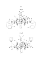
[012] A Figura 1 mostra de forma esquemática, o dispositivo de acordo com a invenção, no qual, uma fonte com luz polarizada atua no material da fibra (flocos de fibra), assim como, nos corpos estranhos e atua em conjunto com um detector,[012] Figure 1 shows schematically the device according to the invention, in which a source with polarized light acts on the fiber material (fiber flakes), as well as on foreign bodies and acts together with a detector,
[013] A Figura 2 mostra de forma esquemática, um dispositivo de acordo com Figura 1 com auxílio de espelhos,[013] Figure 2 shows schematically a device according to Figure 1 with the aid of mirrors,
[014] A Figura 3 mostra um dispositivo com mais de um dispositivo de detecção,[014] Figure 3 shows a device with more than one detection device,
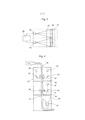
[015] A Figura 4 mostra a integração do dispositivo de detecção em uma máquina com ponto de extração contínuo com dispositivo de descarte posterior,[015] Figure 4 shows the integration of the detection device in a machine with a continuous extraction point with a posterior disposal device,
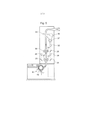
[016] A Figura 5 mostra a integração do dispositivo de acordo com a invenção diretamente atrás de um cilindro abridor,[016] Figure 5 shows the integration of the device according to the invention directly behind an opening cylinder,
[017] A Figura 6 mostra uma modalidade, na qual ambos os locais de inspeção são intercambiáveis e[017] Figure 6 shows a modality, in which both inspection sites are interchangeable and
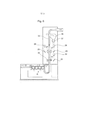
[018] A Figura 7 mostra a instalação de ambos os locais de inspeção depois do cilindro abridor.[018] Figure 7 shows the installation of both inspection sites after the opening cylinder.
[019] A Figura 1 mostra um dispositivo, o qual elimina as desvantagens acima e assegura que todos os métodos de reconhecimento podem ser utilizados em um dispositivo ou em uma máquina:[019] Figure 1 shows a device, which eliminates the above disadvantages and ensures that all recognition methods can be used on a device or on a machine:
[020] A Figura 1 mostra um canal de inspeção 1 com paredes transparentes 3 na área de inspeção 2, pelo qual passam flocos de fibra 4 e os corpos estranhos 5 a serem detectados. Duas câmeras 6 mostram a partir respectivamente de um lado no canal e se encontram no lado que se encontra oposto, em um segundo plano 7 na cor do material. Para a iluminação do segundo plano, são utilizadas, por exemplo, lâmpadas fluorescentes 8, as quais emitem luz branca não- polarizada em áreas visíveis do comprimento de onda. Outros corpos de iluminação 9 iluminam o material da fibra com, por exemplo, luz branca polarizada.[020] Figure 1 shows an inspection channel 1 with
[021] A luz refletida pelos flocos de fibra 4 ou corpos estranhos 5 é recebida pelas câmeras 6 e analisada considerando o nível de luminosidade e cor na análise 10. Preferencialmente, câmera permite aqui receber a luz nos canais na área do comprimento de onda vermelho, verde ou azul e novamente processar em separado. Essa informação de cor é utilizada em uma avaliação para reconhecer e, posteriormente, descartar corpos estranhos em função de seu desvio de nível de luminosidade e de cor ao material da fibra ou do segundo plano. Além das informações de cor, a câmera também pode compreender, contudo, o estado de polarização simultâneo da luz, ou seja, no caso mais simples, a diferença entre a luz não-polarizada e a luz polarizada. No caso de flocos de fibra, os quais despolarizam a luz polarizada através de reflexão difusa ou, no caso do segundo plano iluminado não- polarizado, a câmera determina o estado de polarização como não-polarizado.[021] The light reflected by the fiber flakes 4 or
[022] No caso de corpos de material sintético brilhosos, por exemplo, folhas, tiras de PP ou similares, a luz agora polarizada, com a qual o canal é iluminado, é agora refletida em sua superfície brilhosa, sendo que a luz refletida permanece essencialmente além disso polarizada. A câmera vê, nesse caso, também a luz polarizada. Visto que a câmera está na posição de diferenciar o estado de polarização, por exemplo, pode diferenciar se se trata de luz polarizada ou não-polarizada, a análise também pode diferenciar, dessa maneira, flocos de fibra de corpos estranhos brilhosos e descartar os mesmos, posteriormente.[022] In the case of glossy synthetic material bodies, for example, sheets, strips of PP or similar, the now polarized light, with which the channel is illuminated, is now reflected on its glossy surface, with the reflected light remaining essentially further polarized. In this case, the camera also sees polarized light. Since the camera is in a position to differentiate the polarization state, for example, it can differentiate whether it is polarized or non-polarized light, the analysis can also differentiate, in this way, fiber flakes from shiny foreign bodies and discard them , posteriorly.
[023] Diversas pequenas fontes de luz separadas, por exemplo, LEDs, são utilizadas como fonte de luz 15 para a irradiação do material de fibra e do corpo estranho. A luz polarizada é gerada, por exemplo, por filtros de polarização 13. Esses são laminados preferencialmente como folhas de polarização em uma placa de vidro 14 ou entre duas placas de vidro. 0 fator decisivo para uma área de detecção elevada pelo reconhecimento da superfície brilhosa é que essa luz polarizada se irradia a partir de uma área angular a maior possível sobre o material. Uma disposição ideal circular das fontes de luz ou um alinhamento individual dessas fontes de luz no local de inspeção 17 não é, contudo, economicamente realizável. Faz mais sentido dispor as fontes de luz 15 de forma segmentada em uma superfície plana 16, por exemplo, uma placa de circuito impresso eletrônica. Visto que a fonte de luz então não é direcionada parcialmente sobre o próprio local de inspeção 17, a iluminação parcial é equipada, por exemplo, com lentes escalonadas de Fresnel 18, as quais direcionam a luz na direção desejada 19. De forma alternativa, essas lentes escalonadas de Fresnel também podem ser substituídas por folhas de direcionamento de direção de reprodução holográfica 20. Para a equalização da luz, pode ser, além disso, razoável equipar a iluminação 9 com outras folhas difusoras de reprodução holográfica 21.[023] Several small separate light sources, for example, LEDs, are used as a
[024] Para que as placas de vidro que se separam do ponto de extração do material a partir do espaço da câmera não sejam reconhecidas por seu próprio brilho, algumas medidas são necessárias. Primeiramente, a câmera 6 é disposta de tal modo que essa vê, na posição 22, no ângulo de 90°, sobre a placa de vidro 3. Nessa disposição, qualquer luz das iluminações 9 não pode, desse modo, irradiar na placa de vidro, que a mesma pode ser registrada na câmera como brilho. Nos locais onde isso não é possível, por exemplo, 23, são utilizadas ou placas de vidro 3 não-refletoras, ou, contudo, as iluminações 9 são disfarçadas no local adequado por meio de anteparos 24.[024] In order for the glass plates that separate from the point of extraction of the material from the camera space not to be recognized by their own brightness, some measures are necessary. Firstly,
[025] A Figura 2 mostra a utilização desse princípio com o auxílio de espelhos 25 para aumentar a distância entre a câmera e o local de inspeção com o intuito de cobrir uma maior largura útil de trabalho.[025] Figure 2 shows the use of this principle with the aid of
[026] Em larguras de canal maiores, pode ser vantajoso dividir vários dispositivos de detecção segundo as Figuras 1 a 2 pela largura útil de trabalho de modo que cada seja apropriada apenas para uma seção. Mas aqui também é válido que, para cada seção, ambos os métodos de reconhecimento podem ser realizados com apenas um detector e uma unidade de análise.[026] At larger channel widths, it may be advantageous to divide several detection devices according to Figures 1 to 2 by the useful working width so that each is suitable for only one section. But here it is also valid that, for each section, both recognition methods can be performed with only one detector and one analysis unit.
[027] A Figura 3 mostra uma tal disposição, a partir de uma direção vista com dispositivo de transporte de material vertical ao plano de representação, no qual vários dispositivos de detecção 26 estão dispostos uns ao lado dos outros, para cobrir uma maior largura útil de trabalho. Nos módulos de iluminação 27 estão concentrados os componentes 7, 8, 9 segundo a Figura. 0 número 29 mostra, por exemplo, uma unidade de análise na qual estão conectados vários dispositivos de detecção.[027] Figure 3 shows such an arrangement, from a direction seen with a material transport device vertical to the representation plane, in which
[028] A Figura 4 mostra a integração dos dispositivos de detecção segundo as Figuras 1 a 3 em uma máquina com ponto de extração contínuo com dispositivo de descarte posterior. 0 dispositivo de detecção é complementado com um dispositivo que permite reconhecer corpos estranhos com luz transmitida polarizada 30 em combinação com luz UV 31 transparente ou semitransparente ou fluorescente. Aqui é utilizada uma câmera a cores 32 normal. Pelos apoios de propulsão 33, corpos estranhos reconhecidos são transportados a partir dos locais de inspeção 34 e 35 no espaço de resíduo 3 6 a partir de onde os mesmos são transportados por uma eclusa de roda celular 37 a partir da máquina.[028] Figure 4 shows the integration of the detection devices according to Figures 1 to 3 in a machine with a continuous extraction point with a posterior disposal device. The detection device is complemented with a device for recognizing foreign bodies with polarized transmitted
[029] A Figura 5 mostra a integração dos dispositivos segundo as Figuras 1 a 3 diretamente de um cilindro abridor. A Figura 6 mostra uma variante na qual ambos os locais de inspeção são intercambiáveis.[029] Figure 5 shows the integration of the devices according to Figures 1 to 3 directly from an opening cylinder. Figure 6 shows a variant in which both inspection sites are interchangeable.
[030] A Figura 7 mostra a instalação de ambos os locais de inspeção depois do cilindro abridor.[030] Figure 7 shows the installation of both inspection sites after the opening cylinder.
Claims (16)
Applications Claiming Priority (3)
| Application Number | Priority Date | Filing Date | Title |
|---|---|---|---|
| DE102013010468.8A DE102013010468A1 (en) | 2013-06-24 | 2013-06-24 | Apparatus in the spinning preparation for the detection of foreign parts made of plastic, such as polypropylene tapes, fabrics and films u. Like. In or between fiber flakes, z. B. made of cotton |
| DE102013010468.8 | 2013-06-24 | ||
| PCT/EP2014/001103 WO2014206508A1 (en) | 2013-06-24 | 2014-04-25 | Device in spinning preparation for identifying foreign bodies made of plastics material, such as polypropylene tapes, fabrics and films or the like in or among fibre flocks, for example made of cotton |
Publications (3)
| Publication Number | Publication Date |
|---|---|
| BR112015029552A2 BR112015029552A2 (en) | 2017-07-25 |
| BR112015029552B1 true BR112015029552B1 (en) | 2020-09-15 |
| BR112015029552B8 BR112015029552B8 (en) | 2022-07-05 |
Family
ID=50630748
Family Applications (1)
| Application Number | Title | Priority Date | Filing Date |
|---|---|---|---|
| BR112015029552A BR112015029552B8 (en) | 2013-06-24 | 2014-04-25 | WIRING PREPARATION DEVICE FOR THE RECOGNITION OF SYNTHETIC MATERIAL FOREIGN BODIES IN OR BETWEEN FIBER FLAKES |
Country Status (5)
| Country | Link |
|---|---|
| EP (1) | EP3014253B1 (en) |
| CN (1) | CN105393109B (en) |
| BR (1) | BR112015029552B8 (en) |
| DE (1) | DE102013010468A1 (en) |
| WO (1) | WO2014206508A1 (en) |
Families Citing this family (11)
| Publication number | Priority date | Publication date | Assignee | Title |
|---|---|---|---|---|
| EP2942114B1 (en) * | 2014-05-09 | 2019-02-27 | Baumer Inspection GmbH | Method for detecting foreign bodies |
| DE102015118788A1 (en) | 2015-11-03 | 2017-05-04 | TRüTZSCHLER GMBH & CO. KG | Lighting unit for a device for foreign part recognition for spinning preparation |
| DE102015118847A1 (en) | 2015-11-03 | 2017-05-04 | TRüTZSCHLER GMBH & CO. KG | Device for detecting foreign particles in spinning mill preparation |
| DE102015118848A1 (en) | 2015-11-03 | 2017-05-04 | TRüTZSCHLER GMBH & CO. KG | Device for detecting foreign particles in spinning mill preparation |
| DE102015118795A1 (en) | 2015-11-03 | 2017-05-04 | Trützschler GmbH & Co Kommanditgesellschaft | Lighting unit for a device for foreign part recognition for spinning preparation |
| CN105951415B (en) * | 2016-07-21 | 2019-05-28 | 凌云光技术集团有限责任公司 | A kind of light color or transparent foreign fiber detection system |
| DE102017121359A1 (en) * | 2017-09-14 | 2019-03-14 | TRüTZSCHLER GMBH & CO. KG | Device for detecting and eliminating foreign parts in or between fiber material |
| CN107727580A (en) * | 2017-10-30 | 2018-02-23 | 凌云光技术集团有限责任公司 | Foreign Fiber Detecting Device and method |
| DE102019115138B3 (en) * | 2019-06-05 | 2020-12-10 | TRüTZSCHLER GMBH & CO. KG | Card, fleece guide element, spinning preparation plant and method for detecting interfering particles |
| DE102021109287A1 (en) * | 2021-04-14 | 2022-10-20 | Krones Aktiengesellschaft | Apparatus and method for inspecting cans |
| CN117716816A (en) * | 2023-10-17 | 2024-03-19 | 石河子大学 | A mulch detection and hook-tooth removal system |
Family Cites Families (8)
| Publication number | Priority date | Publication date | Assignee | Title |
|---|---|---|---|---|
| CH686803A5 (en) * | 1993-09-09 | 1996-06-28 | Luwa Ag Zellweger | Method and apparatus for detecting foreign substances in a textile test material. |
| BE1010882A5 (en) * | 1997-01-28 | 1999-02-02 | Barco Nv | A DETECTOR foreign fibers and foreign MATERIALS BASED ON ABSORPTION MEASUREMENT OF LIGHT AND SIMILAR DETECTION. |
| EP1123995B1 (en) * | 2000-02-09 | 2003-09-10 | Jossi Holding AG | Method and apparatus for controlling a textile fibre processing plant, especially for cotton fibres |
| DE10347240B4 (en) | 2003-10-10 | 2015-10-15 | Trützschler GmbH & Co Kommanditgesellschaft | Apparatus in the spinning preparation for detecting foreign parts made of plastic in fiber flakes |
| DE102008031199B4 (en) | 2008-07-03 | 2024-06-13 | Trützschler Group SE | Device in spinning preparation, ginning or similar for detecting foreign parts made of plastic, such as polypropylene or similar. |
| DE102008034385B4 (en) * | 2008-07-23 | 2025-04-30 | Trützschler Group SE | Device in spinning preparation, ginning or similar for detecting foreign substances in or between fiber material, especially cotton |
| DE102008058254B4 (en) * | 2008-11-19 | 2026-02-12 | Trützschler Group SE | Device in spinning preparation, ginning, or the like for detecting and removing foreign substances in or between fiber material, especially cotton. |
| DE102010055523A1 (en) * | 2010-12-22 | 2012-06-28 | Trützschler GmbH & Co Kommanditgesellschaft | Apparatus in the spinning preparation for the detection of foreign parts made of plastic, such as polypropylene tapes, fabrics and films u. like. |
-
2013
- 2013-06-24 DE DE102013010468.8A patent/DE102013010468A1/en not_active Withdrawn
-
2014
- 2014-04-25 EP EP14720896.1A patent/EP3014253B1/en active Active
- 2014-04-25 CN CN201480032992.4A patent/CN105393109B/en active Active
- 2014-04-25 WO PCT/EP2014/001103 patent/WO2014206508A1/en not_active Ceased
- 2014-04-25 BR BR112015029552A patent/BR112015029552B8/en active IP Right Grant
Also Published As
| Publication number | Publication date |
|---|---|
| DE102013010468A1 (en) | 2014-12-24 |
| CN105393109B (en) | 2019-04-02 |
| BR112015029552B8 (en) | 2022-07-05 |
| EP3014253B1 (en) | 2021-01-20 |
| BR112015029552A2 (en) | 2017-07-25 |
| WO2014206508A1 (en) | 2014-12-31 |
| EP3014253A1 (en) | 2016-05-04 |
| CN105393109A (en) | 2016-03-09 |
Similar Documents
| Publication | Publication Date | Title |
|---|---|---|
| BR112015029552B1 (en) | WIRING PREPARATION DEVICE FOR THE RECOGNITION OF STRANGE BODIES OF SYNTHETIC MATERIAL, ON OR BETWEEN FIBER FLAKES | |
| BRPI1105736B1 (en) | DEVICE IN A WIRING WORKSHOP FOR RECOGNITION OF STRANGE PLASTIC PARTS WITHIN OR BETWEEN FIBER GROUPS AND THEIR USE | |
| HRP20241456T1 (en) | System and method for reading features in reverse vending machines | |
| ITMI990323A1 (en) | CONTAINER INSPECTION MACHINE | |
| AU2011273522B2 (en) | Method and device for measuring optical properties of an optically variable marking applied to an object | |
| JP2010519515A5 (en) | ||
| BR112020001269A2 (en) | inspection device with colored lighting | |
| BR112016009951B1 (en) | apparatus for inspecting a flow of matter; systems comprising a first apparatus and a second apparatus; and systems comprising the apparatus | |
| KR20090105424A (en) | Security print authenticity identifier using mobile phone | |
| BRPI0902004B1 (en) | apparatus in a spinning preparation, ginning or similar installation for the detection of foreign matter in or between fiber material, especially cotton | |
| KR20100066547A (en) | Security marking authentication device | |
| CN108136600A (en) | system | |
| KR102921902B1 (en) | Optical detection equipment, multi-spectral led light source box and lighting method | |
| JP6415913B2 (en) | Line lighting device and visual inspection system | |
| CN118019971A (en) | Bottom inspection device for glass bottles | |
| TW201314196A (en) | Optical variable entity verification device and method | |
| ES2623146T3 (en) | Arrangement to capture an image of a band of print material | |
| BR102015004751B1 (en) | 2D BARCODE SCANNER | |
| RU2008124903A (en) | ACCOUNT DEVICE FOR SMALL KITS | |
| JP7312448B2 (en) | Visual aid device | |
| EP2656131B1 (en) | Lens and illumination apparatus having the same | |
| ES2390845T3 (en) | Procedure, lighting device and system for spectral classification | |
| BR112018008717B1 (en) | Device for detecting impurities in wiring preparation | |
| BR112015029542B1 (en) | Apparatus in the preparation of a spinning room, a ginning room or the like to recognize foreign bodies or imperfections in a fiber material stream or between fiber tufts | |
| DE502004003454D1 (en) | Lighting device for a security camera |
Legal Events
| Date | Code | Title | Description |
|---|---|---|---|
| B06F | Objections, documents and/or translations needed after an examination request according [chapter 6.6 patent gazette] | ||
| B06U | Preliminary requirement: requests with searches performed by other patent offices: procedure suspended [chapter 6.21 patent gazette] | ||
| B09A | Decision: intention to grant [chapter 9.1 patent gazette] | ||
| B16A | Patent or certificate of addition of invention granted [chapter 16.1 patent gazette] |
Free format text: PRAZO DE VALIDADE: 20 (VINTE) ANOS CONTADOS A PARTIR DE 25/04/2014, OBSERVADAS AS CONDICOES LEGAIS. |
|
| B25A | Requested transfer of rights approved |
Owner name: TRUETZSCHLER GROUP SE (DE) |