BR112015013508B1 - method of producing a physical prototype - Google Patents
method of producing a physical prototype Download PDFInfo
- Publication number
- BR112015013508B1 BR112015013508B1 BR112015013508-0A BR112015013508A BR112015013508B1 BR 112015013508 B1 BR112015013508 B1 BR 112015013508B1 BR 112015013508 A BR112015013508 A BR 112015013508A BR 112015013508 B1 BR112015013508 B1 BR 112015013508B1
- Authority
- BR
- Brazil
- Prior art keywords
- virtual
- prototype
- brackets
- bracket
- physical
- Prior art date
Links
Images


Classifications
-
- A—HUMAN NECESSITIES
- A61—MEDICAL OR VETERINARY SCIENCE; HYGIENE
- A61C—DENTISTRY; APPARATUS OR METHODS FOR ORAL OR DENTAL HYGIENE
- A61C7/00—Orthodontics, i.e. obtaining or maintaining the desired position of teeth, e.g. by straightening, evening, regulating, separating, or by correcting malocclusions
- A61C7/002—Orthodontic computer assisted systems
-
- A—HUMAN NECESSITIES
- A61—MEDICAL OR VETERINARY SCIENCE; HYGIENE
- A61C—DENTISTRY; APPARATUS OR METHODS FOR ORAL OR DENTAL HYGIENE
- A61C7/00—Orthodontics, i.e. obtaining or maintaining the desired position of teeth, e.g. by straightening, evening, regulating, separating, or by correcting malocclusions
- A61C7/12—Brackets; Arch wires; Combinations thereof; Accessories therefor
- A61C7/14—Brackets; Fixing brackets to teeth
-
- A—HUMAN NECESSITIES
- A61—MEDICAL OR VETERINARY SCIENCE; HYGIENE
- A61C—DENTISTRY; APPARATUS OR METHODS FOR ORAL OR DENTAL HYGIENE
- A61C13/00—Dental prostheses; Making same
- A61C13/0003—Making bridge-work, inlays, implants or the like
- A61C13/0006—Production methods
- A61C13/0019—Production methods using three dimensional printing
-
- A—HUMAN NECESSITIES
- A61—MEDICAL OR VETERINARY SCIENCE; HYGIENE
- A61C—DENTISTRY; APPARATUS OR METHODS FOR ORAL OR DENTAL HYGIENE
- A61C7/00—Orthodontics, i.e. obtaining or maintaining the desired position of teeth, e.g. by straightening, evening, regulating, separating, or by correcting malocclusions
- A61C7/12—Brackets; Arch wires; Combinations thereof; Accessories therefor
- A61C7/14—Brackets; Fixing brackets to teeth
- A61C7/146—Positioning or placement of brackets; Tools therefor
-
- B—PERFORMING OPERATIONS; TRANSPORTING
- B33—ADDITIVE MANUFACTURING TECHNOLOGY
- B33Y—ADDITIVE MANUFACTURING, i.e. MANUFACTURING OF THREE-DIMENSIONAL [3-D] OBJECTS BY ADDITIVE DEPOSITION, ADDITIVE AGGLOMERATION OR ADDITIVE LAYERING, e.g. BY 3-D PRINTING, STEREOLITHOGRAPHY OR SELECTIVE LASER SINTERING
- B33Y80/00—Products made by additive manufacturing
-
- A—HUMAN NECESSITIES
- A61—MEDICAL OR VETERINARY SCIENCE; HYGIENE
- A61C—DENTISTRY; APPARATUS OR METHODS FOR ORAL OR DENTAL HYGIENE
- A61C13/00—Dental prostheses; Making same
- A61C13/0003—Making bridge-work, inlays, implants or the like
- A61C13/0006—Production methods
- A61C13/0013—Production methods using stereolithographic techniques
-
- A—HUMAN NECESSITIES
- A61—MEDICAL OR VETERINARY SCIENCE; HYGIENE
- A61C—DENTISTRY; APPARATUS OR METHODS FOR ORAL OR DENTAL HYGIENE
- A61C7/00—Orthodontics, i.e. obtaining or maintaining the desired position of teeth, e.g. by straightening, evening, regulating, separating, or by correcting malocclusions
- A61C7/12—Brackets; Arch wires; Combinations thereof; Accessories therefor
- A61C7/14—Brackets; Fixing brackets to teeth
- A61C7/145—Lingual brackets
-
- B—PERFORMING OPERATIONS; TRANSPORTING
- B33—ADDITIVE MANUFACTURING TECHNOLOGY
- B33Y—ADDITIVE MANUFACTURING, i.e. MANUFACTURING OF THREE-DIMENSIONAL [3-D] OBJECTS BY ADDITIVE DEPOSITION, ADDITIVE AGGLOMERATION OR ADDITIVE LAYERING, e.g. BY 3-D PRINTING, STEREOLITHOGRAPHY OR SELECTIVE LASER SINTERING
- B33Y10/00—Processes of additive manufacturing
Abstract
"MÉTODO DE PRODUÇÃO DE UM PROTÓTIPO FÍSICO QUE REPRESENTA UM FORMATO COMPOSTO DO FORMATO POSITIVO DA ARCADA DENTÁRIA DE UM PACIENTE E DO FORMATO POSITIVO DE UM CONJUNTO DE ANÁLOGOS, PROTÓTIPO FÍSICO, KIT DE PARTES E MÉTODO DE PRODUÇÃO DE UMA MOLDEIRA DE TRANSFERÊNCIA" A presente invenção refere-se a um método para produção de um protótipo físico, o método compreende as etapas de fornecer uma arcada dentária virtual, um conjunto virtual de bráquetes ortodônticos para a arcada dentária virtual e um conjunto virtual de análogos. Cada análogo é associado a um bráquete virtual do conjunto de bráquetes e o formato de pelo menos um dentre os análogos, difere do formato do bráquete associado. O método compreende adicionalmente as etapas de fornecer um protótipo virtual no qual a arcada dentária virtual e o conjunto de análogos virtuais são combinados, e fabricar o protótipo físico com base no protótipo virtual. O protótipo físico representa um formato composto do formato da arcada dentária e o formato do conjunto de análogos. A invenção facilita a ligação de bráquetes aos dentes de um paciente."PRODUCTION METHOD OF A PHYSICAL PROTOTYPE THAT REPRESENTS A COMPOSITE FORMAT OF THE PATIENT'S DENTAL ARCADE AND THE POSITIVE FORMAT OF A SET OF ANALOGS, PHYSICAL PROTOTYPE, PARTS KIT AND A METHOD OF PRODUCTION OF A METHOD OF PRODUCTION OF A METHOD OF PRODUCTION invention refers to a method for producing a physical prototype, the method comprises the steps of providing a virtual dental arch, a virtual set of orthodontic brackets for the virtual dental arch and a virtual set of analogues. Each analogue is associated with a virtual bracket of the set of brackets and the format of at least one of the analogs differs from the format of the associated bracket. The method further comprises the steps of providing a virtual prototype in which the virtual dental arch and the set of virtual analogues are combined, and making the physical prototype based on the virtual prototype. The physical prototype represents a shape composed of the shape of the dental arch and the shape of the set of analogues. The invention facilitates the attachment of brackets to a patient's teeth.
Description
[001] A invenção está relacionada a um método para fabricação de um protótipo físico que representa um formato composto do formato da arcada dentária de um paciente e o formato de um conjunto de análogos. Os análogos aproximam ou replicam o formato de bráquetes ortodônticos. O protótipo físico representa particularmente uma posição precisa dos bráquetes e facilita a fabricação de uma moldeira de transferência para os bráquetes.[001] The invention relates to a method for manufacturing a physical prototype that represents a shape composed of the shape of a patient's dental arch and the shape of a set of analogues. The analogs approximate or replicate the orthodontic bracket format. The physical prototype particularly represents a precise position of the brackets and facilitates the manufacture of a transfer tray for the brackets.
[002] Os bráquetes ortodônticos são usados em tratamentos ortodônticos para mover um ou mais dentes desde uma posição inicial (chamada, às vezes, como má posição ou má oclusão) até uma posição desejada na dentição de um paciente. Por exemplo, por meio de um tratamento ortodôntico, os dentes do paciente podem ser movidos de modo que as laterais dos lábios fiquem alinhadas entre si, para alcançar ou maximizar uma aparência agradável do ponto de vista estético de toda a dentição. Adicionalmente em alguns casos, um ou mais dentes podem ser movidos para corrigir uma má oclusão. O movimento de dentes é tipicamente conseguido por um fio (archwire) elástico pré-tracionado que é fixado, via bráquetes, aos dentes, e que aplica uma força aos dentes na direção da posição desejada em um período de tempo maior.[002] Orthodontic brackets are used in orthodontic treatments to move one or more teeth from an initial position (sometimes called a malposition or malocclusion) to a desired position in a patient's dentition. For example, through orthodontic treatment, the patient's teeth can be moved so that the sides of the lips are aligned with each other, to achieve or maximize a pleasing appearance from the aesthetic point of view of the entire dentition. In addition, in some cases, one or more teeth can be moved to correct a malocclusion. The movement of teeth is typically achieved by a pre-pulled elastic archwire that is fixed, via brackets, to the teeth, and which applies a force to the teeth in the direction of the desired position over a longer period of time.
[003] Os bráquetes são tipicamente colados aos dentes do paciente e o fio elástico é conectado aos bráquetes. O fio é tipicamente conformado para corresponder à posição dos bráquetes na posição desejada dos dentes, de modo que na posição inicial dos dentes, o fio possa ser conectado aos bráquetes apenas sob pré-tensionamento. Consequentemente, o fio (archwire), uma vez que esteja instalado nos bráquetes, é elasticamente deformado ou pré-tensionado na posição inicial dos dentes e a força de restauração para voltar ao formato não deformado do fio, faz com que os dentes sejam impelidos na direção da posição desejada.[003] The brackets are typically glued to the patient's teeth and the elastic thread is connected to the brackets. The wire is typically shaped to match the position of the brackets in the desired position of the teeth, so that at the initial position of the teeth, the wire can be connected to the brackets only under pre-tensioning. Consequently, the wire (archwire), once installed in the brackets, is elastically deformed or pre-tensioned in the initial position of the teeth and the restoring force to return to the undeformed shape of the wire, causes the teeth to be pushed in the direction of the desired position.
[004] Os assim chamados sistemas de planejamento de tratamento têm sido usados para determinar a posição desejada dos dentes em uma simulação em computador antes de qualquer tratamento real. Tal sistema de planejamento ajuda, por exemplo, a evitar colisões entre os dentes e os bráquetes nas posições do dente fora da posição inicial, e permite ainda que os bráquetes e o fio sejam projetados e dispostos para corresponder a uma série de situações clínicas, por exemplo, com a posição dos dentes na posição inicial, na posição desejada e posições entre. Em particular para bráquetes linguais, tal planejamento de tratamento é amplamente usado. Com frequência, os bráquetes linguais têm um design personalizado individualmente para cada dente e paciente porque, além das superfícies labiais de um dente, as superfícies linguais podem variar bastante de formato com relação uma à outra, de modo que simplesmente não pode ser usado um formato de bráquete "um serve para todos". Alguns sistemas de planejamento de tratamento também permitem projetar bráquetes personalizados que correspondem precisamente a uma superfície do dente e às situações clínicas necessárias de um paciente. Consequentemente, os bráquetes personalizados tipicamente têm que ser colocados precisamente nas posições nos dentes que são predeterminadas durante o planejamento do tratamento. Para facilitar um posicionamento preciso dos bráquetes nos dentes de um paciente e para referência do ortodontista, os bráquetes são fornecidos, com frequência, pré-posicionados, em um modelo de gesso que replica os dentes do paciente.[004] The so-called treatment planning systems have been used to determine the desired position of the teeth in a computer simulation before any real treatment. Such a planning system helps, for example, to avoid collisions between the teeth and the brackets in the positions of the tooth outside the initial position, and also allows the brackets and the wire to be designed and arranged to correspond to a series of clinical situations, for example. example, with the position of the teeth in the initial position, in the desired position and positions in between. In particular for lingual brackets, such treatment planning is widely used. Often, lingual brackets are individually designed for each tooth and patient because, in addition to the lip surfaces of a tooth, the lingual surfaces can vary greatly in shape from one another, so that one shape simply cannot be used. bracket "one fits all". Some treatment planning systems also allow you to design custom brackets that precisely match a tooth surface and a patient's required clinical situations. Consequently, custom brackets typically have to be placed precisely at the positions on the teeth that are predetermined during treatment planning. To facilitate accurate positioning of brackets on a patient's teeth and for reference by the orthodontist, brackets are often supplied pre-positioned in a plaster model that replicates the patient's teeth.
[005] Tal modelo de gesso, no qual os bráquetes são colocados, é usado às vezes em ortodontia para fazer uma assim chamada, moldeira de transferência para facilitar o posicionamento do bráquete nos dentes de um paciente. Tipicamente, uma moldeira de transferência é adaptada para manter um conjunto completo de bráquetes na posição predeterminada e permitir que os bráquetes sejam colocados e ligados aos dentes em uma etapa.[005] Such a plaster model, in which the brackets are placed, is sometimes used in orthodontics to make a so-called transfer tray to facilitate the positioning of the bracket on a patient's teeth. Typically, a transfer tray is adapted to hold a complete set of brackets in the predetermined position and allow the brackets to be placed and attached to the teeth in one step.
[006] Por exemplo, US 7.020.963 apresenta um aparelho de ligação indireto que é feito colocando-se, inicialmente, material espaçador em uma réplica da estrutura do dente do paciente. Então, uma moldeira é formada sobre o material espaçador e endurecido. A seguir, o material espaçador é removido da réplica dos dentes e aparelhos ortodônticos são colocados na réplica nos locais desejados. Um material de matriz é colocado entre a moldeira e a réplica e é deixado a endurecer. A moldeira e os bráquetes (que são embutidos em uma parede interna da moldeira) são então separados do modelo de gesso.[006] For example, US 7,020,963 features an indirect connection device that is made by initially placing spacer material in a replica of the patient's tooth structure. Then, a tray is formed on the spacer material and hardened. Then, the spacer material is removed from the replica of the teeth and orthodontic appliances are placed on the replica in the desired locations. A matrix material is placed between the tray and the replica and is allowed to harden. The tray and the brackets (which are embedded in an internal wall of the tray) are then separated from the plaster model.
[007] Em um outro exemplo como revelados no WO 01/80761, um software de planejamento de tratamento superpõe virtualmente os bráquetes aos dentes para gerar um modelo tridimensional que compreende os dentes tridimensionais mais os bráquetes virtuais em suas localizações pretendidas. Esse modelo tridimensional é fornecido a um instrumento de estereolitografia (SLA - stereo lithography) para fabricar um modelo plástico dos dentes tendo os bráquetes superpostos a eles. Uma folha termoplástica é colocada acima do modelo SLA e o modelo e a folha são colocados dentro de uma câmara de pressão. A câmara é pressurizada de modo que a folha envolva a dentição e os bráquetes. Assim, a folha obtém pequenas endentações onde os bráquetes podem estar situados.[007] In another example as revealed in WO 01/80761, treatment planning software virtually superimposes brackets on teeth to generate a three-dimensional model that comprises three-dimensional teeth plus virtual brackets in their intended locations. This three-dimensional model is supplied to a stereolithography instrument (SLA - stereo lithography) to manufacture a plastic model of the teeth with the brackets superimposed on them. A thermoplastic sheet is placed above the SLA model and the model and sheet are placed inside a pressure chamber. The chamber is pressurized so that the sheet surrounds the dentition and the brackets. Thus, the sheet obtains small indentations where the brackets can be located.
[008] Embora uma variedade de soluções diferentes para posicionamento preciso de bráquetes esteja disponível, ainda existe um desejo de fornecer uma solução que ajude a maximizar a precisão do posicionamento e minimizar os custos do tratamento ortodôntico.[008] Although a variety of different solutions for accurate positioning of brackets are available, there is still a desire to provide a solution that helps to maximize positioning accuracy and minimize orthodontic treatment costs.
[009] A invenção, em um aspecto, refere-se a um método para fabricação de um protótipo físico conforme definido na reivindicação 1. O protótipo físico representa um formato composto do formato positivo da arcada dentária de um paciente e o formato positivo de um conjunto de análogos. O formato positivo da arcada dentária de um paciente e o formato positivo de um conjunto de análogos, se superpõem, de preferência, aditivamente, por exemplo, sem sobreposição e posicionados diretamente em posição adjacente. O formato da arcada dentária e do conjunto de análogos formam juntos, de preferência, uma peça contígua, por exemplo, não podem ser montados a partir de análogos pré- acabados, por um lado, e uma arcada dentária pré-acabada, por outro lado.[009] The invention, in one aspect, relates to a method for manufacturing a physical prototype as defined in
[010] O método compreende as etapas de: - fornecer uma arcada dentária virtual que replique ao menos parte da arcada dentária de um paciente; - fornecer um conjunto virtual de bráquetes ortodônticos à arcada dentária virtual; - fornecer um conjunto virtual de análogos, cada análogo sendo associado a um bráquete virtual do conjunto virtual de bráquetes, em que um ou mais dos análogos virtuais se aproximam dos formatos de seus bráquetes virtuais associados; - em que os formatos do dito um ou mais dos análogos diferem, cada um, dos formatos de seus bráquetes associados; - fornecer um protótipo virtual no qual a arcada dentária virtual e o conjunto de análogos virtuais sejam combinados; e - fabricar o protótipo físico com base no protótipo virtual.[010] The method comprises the steps of: - providing a virtual dental arch that replicates at least part of a patient's dental arch; - supply a virtual set of orthodontic brackets to the virtual dental arch; - provide a virtual set of analogues, each analog being associated with a virtual bracket of the virtual set of brackets, in which one or more of the virtual analogs approximate the formats of their associated virtual brackets; - in which the formats of said one or more of the analogues differ, each, from the formats of its associated brackets; - provide a virtual prototype in which the virtual dental arch and the set of virtual analogues are combined; and - manufacture the physical prototype based on the virtual prototype.
[011] A invenção pode ser vantajosa na preparação de uma moldeira de transferência para bráquetes. Em particular, a invenção permite, de preferência, fornecer uma moldeira de transferência na qual os bráquetes possam ser colocados de maneira removível e posicionados sem danificar substancialmente a moldeira de transferência. A invenção também é vantajosa pelo fato de que os bráquetes são, de preferência, facilmente colocados na moldeira. Em particular, um usuário que coloque um bráquete na moldeira pode reconhecer uma retroinformação de "encaixe por pressão" perceptível, assim que o bráquete é colocado na posição adequada. Adicionalmente, uma moldeira de transferência preparada pelo uso da invenção permite, de preferência, o posicionamento preciso dos bráquetes, mas a remoção dos bráquetes com forças relativamente baixas. Assim, tal moldeira, após o uso para colar os bráquetes na boca de um paciente, pode ser facilmente removida, pelo qual o risco de destruir (descolar) os bráquetes pode ser minimizado. Adicionalmente, um protótipo físico, conforme pode ser obtido pelo método da invenção, permite tipicamente produzir uma moldeira de transferência pelo dentista ou ortodontista. Portanto, pode não haver necessidade de obter uma moldeira de transferência de um laboratório dentário. Isso permite, por exemplo, refazer uma moldeira, ou uma moldeira parcial, no caso de um bráquete descolar do dente de um paciente. Adicionalmente, a invenção permite fornecer um protótipo físico em que a posição dos bráquetes com relação à arcada dentária seja proporcionada sem tolerâncias de montagem manuais. Assim, uma moldeira de transferência replicada a partir do protótipo é adaptada, de preferência, para posicionar precisamente os bráquetes em relação aos dentes de um paciente. A invenção é particularmente vantajosa pelo fato de permitir um "fluxo de trabalho digital" entre um ortodontista e um fabricante de bráquete para preparação dos bráquetes e da moldeira de transferência. Em particular, o ortodontista pode não precisar enviar um molde de gesso físico dos dentes mal posicionados do paciente para o fabricante de bráquetes. Adicionalmente, a preparação do protótipo físico pode ajudar a minimizar o tempo para preparação porque uma etapa de montagem para colocar manualmente os análogos ou os bráquetes em um modelo físico da arcada dentária, não é necessária.[011] The invention can be advantageous in the preparation of a transfer tray for brackets. In particular, the invention preferably makes it possible to provide a transfer tray in which the brackets can be removably placed and positioned without substantially damaging the transfer tray. The invention is also advantageous in that the brackets are preferably easily placed in the tray. In particular, a user who places a bracket in the tray can recognize a noticeable "snap fit" feedback once the bracket is placed in the proper position. In addition, a transfer tray prepared by the use of the invention preferably allows the precise positioning of the brackets, but the removal of the brackets with relatively low forces. Thus, such a tray, after use to stick the brackets to a patient's mouth, can be easily removed, whereby the risk of destroying (detaching) the brackets can be minimized. In addition, a physical prototype, as can be obtained by the method of the invention, typically allows the production of a transfer tray by the dentist or orthodontist. Therefore, there may be no need to obtain a transfer tray from a dental laboratory. This allows, for example, to remake a tray, or a partial tray, in the case of a bracket detaching from a patient's tooth. Additionally, the invention makes it possible to provide a physical prototype in which the position of the brackets with respect to the dental arch is provided without manual assembly tolerances. Thus, a transfer tray replicated from the prototype is preferably adapted to precisely position the brackets in relation to a patient's teeth. The invention is particularly advantageous in that it allows a "digital workflow" between an orthodontist and a bracket manufacturer to prepare the brackets and transfer tray. In particular, the orthodontist may not need to send a physical plaster cast of the patient's poorly positioned teeth to the bracket manufacturer. In addition, the preparation of the physical prototype can help to minimize the time for preparation because an assembly step to manually place the analogs or brackets on a physical model of the dental arch is not necessary.
[012] Para o propósito desse relatório descritivo, o termo "virtual" refere-se a uma representação tridimensional por computador de um objeto, de preferência, com base em uma representação matemática de um formato tridimensional em forma de dados e que possa ser processada por um computador Tais objetos virtuais na forma de dados, incluindo suas visualizações (por exemplo, molduras de fio ou versões digitais) são amplamente conhecidos no campo de Desenho Auxiliado por Computador (CAD - Computer Aided Design).[012] For the purpose of this specification, the term "virtual" refers to a three-dimensional computer representation of an object, preferably based on a mathematical representation of a three-dimensional format in the form of data and which can be processed by a computer Such virtual objects in the form of data, including their visualizations (for example, wire frames or digital versions) are widely known in the field of Computer Aided Design (CAD).
[013] Para a finalidade do presente relatório descritivo, o termo "conjunto de" refere-se a "uma pluralidade de". Em uma modalidade, um ou mais dentre o conjunto de análogos virtuais representam o formato do bráquete virtual associado, enquanto que os análogos virtuais restantes do mesmo conjunto de análogos virtuais apenas se aproximam do formato do bráquete virtual associado. Nessa modalidade, o formato de um análogo, representando o formato do bráquete virtual associado, corresponde, de preferência, substancialmente exatamente, no formato, ao formato do respectivo bráquete virtual associado. O termo "substancialmente exatamente", neste aspecto, significa que os formatos são exatamente idênticos, exceto pela presença eventual de tolerâncias que possam resultar da fabricação dos análogos. Adicionalmente nessa modalidade, o formato de um análogo que se aproxime do formato do bráquete virtual associado, de preferência difere do formato do respectivo bráquete virtual associado. De preferência, o formato de um análogo que se aproxime do formato do bráquete virtual associado se estende além dos contornos do formato do bráquete virtual associado.[013] For the purpose of this specification, the term "set of" refers to "a plurality of". In one embodiment, one or more of the set of virtual analogues represents the format of the associated virtual bracket, while the remaining virtual analogues of the same set of virtual analogues only approximate the format of the associated virtual bracket. In this modality, the format of an analogue, representing the format of the associated virtual bracket, preferably corresponds, substantially exactly, in format, to the format of the respective associated virtual bracket. The term "substantially exactly", in this respect, means that the formats are exactly identical, except for the possible presence of tolerances that may result from the manufacture of analogues. Additionally in this modality, the format of an analogue that approximates the format of the associated virtual bracket, preferably differs from the format of the respective associated virtual bracket. Preferably, the shape of an analogue that approximates the shape of the associated virtual bracket extends beyond the contours of the shape of the associated virtual bracket.
[014] Em uma modalidade, o método compreende capturar um formato de uma arcada dentária de um paciente e assim fornecer a arcada dentária virtual. O formato de uma arcada dentária de um paciente pode ser capturado por meio de varredura intra-oral de pelo menos partes da dentição do paciente, que inclua os dentes, ou por meio da varredura de um modelo físico, por exemplo, de um molde em gesso dos dentes de um paciente. Os dispositivos de varredura que permitem fornecer uma arcada dentária virtual na forma de dados estão disponíveis, por exemplo, sob a designação Lava™ Scan ST e Lava™ Chairside Oral Scanner C.O.S, ambos da 3M Deutschland GmbH.[014] In one embodiment, the method comprises capturing a shape of a patient's dental arch and thus providing the virtual dental arch. The shape of a patient's dental arch can be captured by intra-oral scanning of at least parts of the patient's dentition, which includes the teeth, or by scanning a physical model, for example, of a mold in plaster of a patient's teeth. Scanning devices that provide a virtual dental arch in the form of data are available, for example, under the designation Lava ™ Scan ST and Lava ™ Chairside Oral Scanner C.O.S, both from 3M Deutschland GmbH.
[015] Em uma modalidade, o método compreende adicionalmente a etapa de posicionar os bráquetes virtuais em relação à arcada dentária virtual. Existem sistemas de planejamento de tratamento que permitem projetar e/ou posicionar bráquetes virtuais em relação a uma arcada dentária virtual com o auxílio do computador. Tal sistema é descrito, por exemplo, em US 7.811.087. Os bráquetes virtuais pode ser ao menos parcialmente projetados e/ou recuperados de um banco de dados. Cada bráquete pode ser automaticamente e/ou manualmente posicionado em relação a um dente virtual que esteja na arcada dentária virtual.[015] In one modality, the method additionally comprises the step of positioning the virtual brackets in relation to the virtual dental arch. There are treatment planning systems that allow you to design and / or position virtual brackets in relation to a virtual dental arch with the aid of a computer. Such a system is described, for example, in US 7,811,087. Virtual brackets can be at least partially designed and / or retrieved from a database. Each bracket can be automatically and / or manually positioned in relation to a virtual tooth that is in the virtual dental arch.
[016] Em uma outra modalidade, o método compreende a etapa de modificar o formato de ao menos um bráquete virtual para formar ao menos um dentre os análogos virtuais. Tal modificação é executada, de preferência, com auxílio do computador, por exemplo, por meio do uso de uma técnica CAD. Consequentemente, o versado na técnica irá reconhecer diversas possibilidades para modificar um formato, por exemplo, pela alteração de um formato existente, adição ou remoção de um formato, virtualmente copiando, cortando, estendendo, reduzindo ou outra técnica adequada. O formato original de qualquer bráquete virtual modificado é armazenado, de preferência, no computador. Dessa forma, o bráquete virtual original pode estar disponível para fabricação de um bráquete físico.[016] In another modality, the method comprises the step of modifying the format of at least one virtual bracket to form at least one among the virtual analogues. Such modification is preferably carried out with the aid of a computer, for example, through the use of a CAD technique. Consequently, the person skilled in the art will recognize several possibilities for modifying a format, for example, by altering an existing format, adding or removing a format, virtually copying, cutting, extending, reducing or another suitable technique. The original format of any modified virtual bracket is preferably stored on the computer. In this way, the original virtual bracket may be available to manufacture a physical bracket.
[017] O conjunto de análogos pode ser fornecido presumindo-se que os bráquetes virtuais modificados e não modificados formem o conjunto de análogos, ao fornecer uma cópia virtual de qualquer bráquete modificado e assumindo qualquer bráquete virtual inalterado como análogo, ou fornecendo uma cópia virtual dos bráquetes virtuais alterados e inalterados para criar os análogos. O versado na técnica será capaz de criar o conjunto de análogos em qualquer modo adequado, por exemplo, por meio de funções disponíveis em um sistema CAD, para fornecer um conjunto de análogos em que o formato de ao menos um dos análogos seja diferente do formato do bráquete associado.[017] The set of analogs can be provided assuming that the modified and unmodified virtual brackets form the set of analogues, by providing a virtual copy of any modified bracket and assuming any virtual bracket unchanged as analogue, or by providing a virtual copy of the altered and unchanged virtual brackets to create the analogues. The person skilled in the art will be able to create the set of analogues in any suitable mode, for example, using functions available in a CAD system, to provide a set of analogues in which the format of at least one of the analogues is different from the format associated bracket.
[018] Em uma modalidade, a etapa de modificação compreende aumentar um volume tridimensional representado pelo bráquete virtual ao modificar seletivamente apenas uma porção do bráquete. Por exemplo, a etapa de modificação pode compreender um achatamento ou redução de uma indentação presente no formato do bráquete. A etapa de modificação pode compreender, adicionalmente, preencher ao menos parcialmente um espaço entre porções do formato do bráquete, ou adicionar uma estrutura virtual ao formato do bráquete. Esses recortes por baixo que podem obstruir a colocação dos bráquetes na moldeira ou, eventualmente, impedir que uma moldeira de transferência seja removida, podem ser minimizados. Adicionalmente, a etapa de modificação pode compreender, opcionalmente, reduzir o volume tridimensional por meio da modificação seletiva de uma outra porção do bráquete. Por exemplo, a etapa de modificação pode compreender um arredondamento de uma aresta para levar em conta a abrasão de um bráquete físico durante uma etapa de tratamento superficial (por exemplo durante remoção de rebarba ou polimento). Adicionalmente, a etapa de modificação pode compreender manter, ou substancialmente, de ao menos uma porção do formato original do bráquete virtual. Dessa forma, o formato de cada análogo virtual pode corresponder substancialmente ao menos parcialmente ao formato de um bráquete virtual do conjunto virtual de bráquetes.[018] In one mode, the modification step comprises increasing a three-dimensional volume represented by the virtual bracket by selectively modifying only a portion of the bracket. For example, the modification step may comprise a flattening or reduction of an indentation present in the bracket format. The modification step may additionally comprise at least partially filling a space between portions of the bracket shape, or adding a virtual structure to the bracket shape. These cutouts underneath that can obstruct the placement of the brackets in the tray or, eventually, prevent a transfer tray from being removed, can be minimized. In addition, the modification step may optionally comprise reducing the three-dimensional volume by means of the selective modification of another portion of the bracket. For example, the modification step may comprise an edge rounding to take into account the abrasion of a physical bracket during a surface treatment step (for example during burr removal or polishing). In addition, the modification step may comprise maintaining, or substantially, at least a portion of the original format of the virtual bracket. In this way, the format of each virtual analogue can correspond substantially at least partially to the format of a virtual bracket of the virtual set of brackets.
[019] Em uma modalidade, o protótipo físico é produzido por fabricação aditiva, por exemplo, uma técnica de criação de protótipos rápida ou de formação. Tal fabricação aditiva também é referida, às vezes, como estereolitografia (SLA - Stereolithography) ou impressão 3D.[019] In one embodiment, the physical prototype is produced by additive manufacturing, for example, a rapid prototyping or training technique. Such additive manufacturing is also sometimes referred to as stereolithography (SLA - Stereolithography) or 3D printing.
[020] Em uma outra modalidade, o método compreende a etapa de fornecer uma moldeira de transferência para o conjunto de bráquetes. A moldeira de transferência é fornecida, de preferência, através de replicação física do formato negativo de pelo menos parte do protótipo físico. A etapa de fornecer a moldeira de transferência pode compreender fornecer um material pastoso ou líquido endurecível, por exemplo, um material curável. Materiais adequados podem ser selecionados dentre.[020] In another mode, the method comprises the step of providing a transfer tray for the set of brackets. The transfer tray is preferably provided through physical replication of the negative shape of at least part of the physical prototype. The step of providing the transfer tray may comprise providing a curable, pasty or liquid material, for example, a curable material. Suitable materials can be selected from among.
[021] De preferência, o material endurecível é transparente ou substancialmente transparente ao menos quando endurecido.[021] Preferably, the curable material is transparent or substantially transparent at least when cured.
[022] Em uma modalidade, o método compreende as etapas de: - fornecer uma cobertura elástica ao protótipo físico para cobrir ao menos parte do lado do dente do protótipo pela cobertura; - fornecer uma cobertura plástica ao protótipo com a cobertura elástica estando disposta entre a cobertura plástica e o protótipo; - deformar a cobertura plástica sobre o protótipo de modo que envolva firmemente ao menos o lado do dente do protótipo com a cobertura elástica contida entre a cobertura plástica e o protótipo; - substituir a cobertura elástica por um material pastoso ou líquido endurecível; e - permitir que o material endurecível endureça.[022] In one embodiment, the method comprises the steps of: - providing an elastic cover to the physical prototype to cover at least part of the prototype tooth side by the cover; - provide a plastic cover to the prototype with the elastic cover being arranged between the plastic cover and the prototype; - deform the plastic cover over the prototype in such a way that it securely engages at least the tooth side of the prototype with the elastic cover contained between the plastic cover and the prototype; - replace the elastic cover with a pasty material or hardenable liquid; and - allowing the curable material to harden.
[023] Em um aspecto particular, a invenção é direcionada a um método de produção de uma moldeira de transferência, compreendendo as etapas de: - fornecer um protótipo físico em um formato que seja parecido ou corresponda a um formato positivo da arcada dentária de um paciente que esteja dotada com um conjunto de bráquetes; - fornecer uma cobertura elástica ao protótipo físico para cobrir ao menos parte do lado do dente do protótipo pela cobertura; - fornecer uma cobertura plástica ao protótipo com a cobertura elástica estando disposta entre a cobertura plástica e o protótipo; - deformar a cobertura plástica em relação ao protótipo de modo que encerre firmemente ao menos o lado do dente do protótipo e de modo que contenha a cobertura elástica entre a cobertura plástica e o protótipo; - substituir a cobertura elástica por um material pastoso ou líquido endurecível; e - permitir que o material endurecível endureça.[023] In a particular aspect, the invention is directed to a method of production of a transfer tray, comprising the steps of: - providing a physical prototype in a format that resembles or corresponds to a positive format of the dental arch of a patient with a set of brackets; - provide an elastic cover to the physical prototype to cover at least part of the prototype tooth side by the cover; - provide a plastic cover to the prototype with the elastic cover being arranged between the plastic cover and the prototype; - deform the plastic cover in relation to the prototype so that it securely encloses at least the tooth side of the prototype and so that it contains the elastic cover between the plastic cover and the prototype; - replace the elastic cover with a pasty material or hardenable liquid; and - allowing the curable material to harden.
[024] A cobertura elástica pode ser produzida a partir de um material selecionado dentre materiais de moldagem dentais, de preferência tendo uma dureza Shore A de cerca de 20 após o endurecimento, e podendo ter uma espessura dentro de uma faixa de cerca de 2 a cerca de 5 mm. A cobertura elástica, tem, de preferência, um tamanho (ou área) que é adequado para envolver ao menos parte dos lados do lábio, dos lados de oclusão e ao menos parte dos lados linguais dos dentes representados no protótipo físico. Adicionalmente, a cobertura elástica pode ser dimensionada para envolver todo o protótipo físico ou múltiplos protótipos físicos. Dessa forma, a cobertura elástica pode ter um formato em U ao longo de um caminho que corresponda aproximadamente ao caminho ao longo do qual os lados de oclusão dos dentes estão dispostos no protótipo. Alternativamente, a cobertura elástica pode ser dimensionada para cobrir, de modo geral, ao menos uma área de projeção de uma ou mais protótipos físicos em um plano aproximadamente paralelo aos lados de oclusão dos dentes no protótipo.[024] The elastic covering can be produced from a material selected from dental impression materials, preferably having a Shore A hardness of about 20 after hardening, and can have a thickness within a range of about 2 to about 5 mm. The elastic covering preferably has a size (or area) that is suitable for wrapping at least part of the sides of the lip, the sides of occlusion and at least part of the lingual sides of the teeth represented in the physical prototype. Additionally, the elastic cover can be dimensioned to involve the entire physical prototype or multiple physical prototypes. In this way, the elastic cover may have a U-shape along a path that roughly corresponds to the path along which the occlusion sides of the teeth are arranged in the prototype. Alternatively, the elastic cover can be dimensioned to cover, in general, at least one projection area of one or more physical prototypes in a plane approximately parallel to the occlusion sides of the teeth in the prototype.
[025] A cobertura plástica (ou cobertura plasticamente deformável, por exemplo termoplasticamente deformável) pode ser produzida, por exemplo, a partir de Duran® disponível junto à Scheu Dental, Alemanha, e pode ter uma espessura dentro de uma faixa de cerca de 0,5 a cerca de 1,5 mm. A cobertura plástica pode ter um tamanho (ou área) que corresponde ao tamanho da cobertura elástica, mas, tem, de preferência, um tamanho maior.[025] The plastic cover (or plastically deformable cover, for example thermoplastic deformable) can be produced, for example, from Duran® available from Scheu Dental, Germany, and can have a thickness within a range of about 0 , 5 to about 1.5 mm. The plastic cover may have a size (or area) that corresponds to the size of the elastic cover, but is preferably a larger size.
[026] A cobertura plástica é deformada, de preferência, por pressão do gás, por exemplo aplicando-se uma pressão ou vácuo apenas a um lado da cobertura para causar uma diferença de pressão relativa no outro lado e, assim, fazer com que a cobertura deforme em relação ao protótipo. A cobertura plástica pode ser aquecida antes e/ou durante o processo de deformação para amolecer o material do qual a cobertura plástica é constituída. Tal, assim denominada, termoformação, pode ser feita com o uso de um dispositivo de termoformação, por exemplo como disponível sob a designação 508DT, da empresa Formech Inc., Chicago, IL, EUA.[026] The plastic cover is preferably deformed by gas pressure, for example by applying a pressure or vacuum only to one side of the cover to cause a relative pressure difference on the other side and thus causing the deformed coverage in relation to the prototype. The plastic cover can be heated before and / or during the deformation process to soften the material of which the plastic cover is made. This, so-called, thermoforming, can be done using a thermoforming device, for example as available under the designation 508DT, from Formech Inc., Chicago, IL, USA.
[027] De preferência, a cobertura plástica é deformada de modo que ela, junto com a cobertura elástica, envolva firmemente os dentes representados no protótipo. Assim, a cobertura elástica age, de preferência, como uma camada espaçadora, fazendo com que a cobertura plástica se forme ao redor dos dentes a uma certa distância determinada pela espessura da cobertura elástica.[027] Preferably, the plastic cover is deformed so that it, together with the elastic cover, firmly envelops the teeth represented in the prototype. Thus, the elastic covering preferably acts as a spacer layer, causing the plastic covering to form around the teeth at a certain distance determined by the thickness of the elastic covering.
[028] Para substituir a cobertura elástica por um material pastoso ou líquido endurecível, a cobertura plástica, se for termoformada, é resfriada naturalmente, de preferência. Assim, a cobertura plástica obtém, de preferência, uma rigidez suficiente para ser manuseada. A cobertura plástica e a cobertura elástica podem ser removidas do protótipo físico, e a cobertura elástica pode ser removido da cobertura plástica. A cobertura plástica, após a deformação, pode ter uma indentação genericamente em formato de rebaixo, o que se aproxima de um formato ampliado proporcional, do ponto de vista tridimensional, dos dentes (incluindo os análogos) representado no protótipo físico. A indentação pode ser preenchida com o material endurecível que pode ser selecionado dentre Kanisil® e Odontosil™. O protótipo pode ser encaixado na cobertura plástica deformada de modo a encerrar o material endurecível entre o protótipo e a cobertura. A quantidade do material endurecível é selecionada, de preferência, de modo que durante o emparelhamento do protótipo e da cobertura, o material endurecível flua ao redor (de preferência para embutir as partes relevantes) dos dentes e análogos representados no protótipo. Para minimizar espaços vazios ou bolhas entre os dentes e o material endurecível, o protótipo encaixado, o material endurecível e a cobertura podem ser expostos a um vácuo ou pressão, por exemplo, por meio do uso de uma autoclave ou câmara de pressão. Subsequentemente, pode-se deixar o material endurecível endurecer ou ele pode ser curado. O material fluxível endurecido é, de preferência, elástico e tem uma dureza Shore entre cerca de 50 shore A e 70 shore A, de preferência, cerca de 60 Shore A. De preferência, o material fluxível endurecido e a cobertura deformada, em combinação, formam a moldeira de transferência.[028] To replace the elastic cover with a pasty material or hardenable liquid, the plastic cover, if it is thermoformed, is naturally cooled, preferably. Thus, the plastic cover preferably obtains sufficient stiffness to be handled. The plastic cover and elastic cover can be removed from the physical prototype, and the elastic cover can be removed from the plastic cover. The plastic cover, after deformation, may have a indentation generally in the form of a recess, which approximates a proportional enlarged format, from the three-dimensional point of view, of the teeth (including the analogues) represented in the physical prototype. The indentation can be filled with the hardenable material that can be selected from Kanisil® and Odontosil ™. The prototype can be fitted to the deformed plastic cover in order to enclose the hardenable material between the prototype and the cover. The quantity of the curable material is preferably selected, so that during the pairing of the prototype and the cover, the curable material flows around (preferably to embed the relevant parts) of the teeth and analogues represented in the prototype. To minimize empty spaces or bubbles between the teeth and the curable material, the fitted prototype, the curable material and the cover can be exposed to a vacuum or pressure, for example, through the use of an autoclave or pressure chamber. Subsequently, the curable material can be allowed to harden or it can be cured. The hardened flowable material is preferably elastic and has a Shore hardness between about 50 shore A and 70 shore A, preferably about 60 Shore A. Preferably, the hardened flowable material and the deformed cover, in combination, form the transfer tray.
[029] O protótipo e a moldeira de transferência, em uma situação de encaixe um com o outro, definem, de preferência, um ou mais eixos de referência ao longo de uma direção na qual a moldeira de transferência é ao menos parcialmente removível do protótipo. Diferentes seções (por exemplo uma seção de um dente) do protótipo e da moldeira de transferência podem definir diferentes eixos de referência (ou eixos de referência ligeiramente diferentes), no entanto, a seguir, faz-se referência como um eixo de referência apenas, por questão de simplicidade. A modificação do formato de um ou mais dos bráquetes compreende, de preferência, uma redução ou eliminação de um corte por baixo formado por pelo menos um dos bráquetes e adequado para travar ou reter a moldeira de transferência contra um movimento ao longo do eixo de referência. Em outras palavras relativas a um formato de bráquete, o formato do análogo associado pode fornecer uma retenção menor da moldeira de transferência emparelhada no protótipo físico.[029] The prototype and the transfer tray, in a situation of fitting with each other, preferably define one or more axes of reference along a direction in which the transfer tray is at least partially removable from the prototype . Different sections (for example a section of a tooth) of the prototype and the transfer tray may define different reference axes (or slightly different reference axes), however, below, reference is made as a reference axis only, for the sake of simplicity. The modification of the shape of one or more of the brackets preferably comprises a reduction or elimination of a cut underneath formed by at least one of the brackets and suitable for locking or retaining the transfer tray against movement along the reference axis . In other words regarding a bracket shape, the shape of the associated analog can provide less retention of the transfer tray paired in the physical prototype.
[030] Em uma modalidade a moldeira de transferência replica o formato negativo apenas de parte do protótipo físico, por exemplo o formato apenas de um análogo e o formato de ao menos parte de um dente na arcada dentária. Uma moldeira de transferência parcial pode permitir, por exemplo, a recolagem ou substituição de um bráquete na boca de um paciente. O protótipo pode ser adaptado de modo que a moldeira de transferência obtenha um ou mais marcadores de separação em posições predeterminadas. Um usuário da moldeira de transferência pode separar (por exemplo, cortar) a moldeira em um marcador de separação e obter, desse modo, uma moldeira de transferência parcial. O protótipo pode, portanto, ser fornecido de modo que ele compreenda uma ou mais saliências ou cristas que replicam os recessos ou entalhes correspondentes na moldeira. Em vez de ou em adição a um marcador de separação, pode ser fornecido um marcador de posição no protótipo na forma de uma estrutura em elevação ou em recesso, como, por exemplo, um marcador de posição que indique o centro de um dente. Adicionalmente, o protótipo pode ser fornecido de modo que ele compreenda números em elevação ou rebaixados que indiquem o número e/ou o número do quadrante do dente. Em uma outra modalidade, o método compreende a etapa de colocar um ou mais bráquetes em respectivos um ou mais receptáculos, em que cada receptáculo corresponde ao formato negativo de um análogo associado ao bráquete. Isso pode ser feito bráquete a bráquete manualmente ou pegando-se um conjunto de bráquetes pré-posicionados em um modelo físico dos dentes do paciente, em que a moldeira de transferência vazia (sem os bráquetes) é encaixada no modelo físico dos dentes do paciente incluindo os bráquetes e separando a moldeira de transferência do modelo dos dentes do paciente. Na última etapa, os bráquetes, de preferência, ficam retidos na moldeira de transferência e são liberados do modelo. Isso pode ser conseguido por meio de uma união temporária relativamente leve entre os bráquetes e o modelo.[030] In one embodiment, the transfer tray replicates the negative shape of only part of the physical prototype, for example the shape of only one analog and the shape of at least part of a tooth in the dental arch. A partial transfer tray may, for example, allow a bracket to be replaced or replaced in a patient's mouth. The prototype can be adapted so that the transfer tray obtains one or more separation markers at predetermined positions. A transfer tray user can separate (for example, cut) the tray on a separation marker and thereby obtain a partial transfer tray. The prototype can therefore be provided so that it comprises one or more ridges or ridges that replicate the corresponding recesses or notches in the tray. Instead of or in addition to a separation marker, a placeholder in the prototype can be provided in the form of a raised or recessed structure, such as, for example, a placeholder that indicates the center of a tooth. In addition, the prototype can be supplied so that it comprises raised or lowered numbers that indicate the number and / or the number of the tooth quadrant. In another modality, the method comprises the step of placing one or more brackets in respective one or more receptacles, in which each receptacle corresponds to the negative shape of an analog associated with the bracket. This can be done bracket by bracket manually or by taking a set of brackets pre-positioned on a physical model of the patient's teeth, in which the empty transfer tray (without the brackets) is fitted to the physical model of the patient's teeth including brackets and separating the transfer tray from the patient's teeth model. In the last step, the brackets, preferably, are retained in the transfer tray and are released from the model. This can be achieved through a relatively light temporary bond between the brackets and the model.
[031] Em um outro aspecto, a invenção está relacionada a um protótipo físico obtido a partir do método de qualquer uma das reivindicações anteriores.[031] In another aspect, the invention relates to a physical prototype obtained from the method of any of the preceding claims.
[032] Ainda em um outro aspecto, a invenção refere-se a um kit de partes, que compreende: - um conjunto de bráquetes sendo adaptado para ser colocado na arcada dentária de um paciente, e - um protótipo físico representando um formato composto do formato positivo da arcada dentária de um paciente e um formato positivo de um conjunto de análogos, em que cada um é associado ao formato de um bráquete do conjunto de bráquetes, e - em que os formatos de um ou mais dos análogos, se aproximam dos formatos de seus bráquetes associados; e - em que o dito um ou mais dos análogos têm, cada um, um formato diferente de seus bráquetes associados.[032] In yet another aspect, the invention relates to a kit of parts, which comprises: - a set of brackets being adapted to be placed in a patient's dental arch, and - a physical prototype representing a format composed of the positive shape of a patient's dental arch and a positive shape of a set of analogues, in which each is associated with the shape of a bracket in the set of brackets, and - in which the shapes of one or more of the analogues, approximate those formats of its associated brackets; and - in which said one or more of the analogs each has a different format than its associated brackets.
[033] Em uma modalidade o kit compreende uma moldeira de transferência para colocar o conjunto de bráquetes na arcada dentária de um paciente. Tal moldeira de transferência pode ser usada para transportar os bráquetes do fabricante de bráquete até um dentista ou ortodontista, e/ou para colar os bráquetes nos dentes de um paciente em uma posição predeterminada pela moldeira de transferência.[033] In one embodiment, the kit comprises a transfer tray to place the set of brackets in a patient's dental arch. Such a transfer tray can be used to transport the brackets from the bracket manufacturer to a dentist or orthodontist, and / or to glue the brackets on a patient's teeth in a position predetermined by the transfer tray.
[034] Em uma outra modalidade, o kit compreende adicionalmente uma ou mais fios para montagem com o conjunto de bráquetes.[034] In another modality, the kit additionally comprises one or more wires for assembly with the set of brackets.
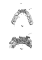
[035] A Figura 1 é uma vista em perspectiva de um protótipo físico de acordo com uma modalidade da invenção;[035] Figure 1 is a perspective view of a physical prototype according to an embodiment of the invention;
[036] A Figura 2 é uma vista parcial ampliada da Figura 1;[036] Figure 2 is an enlarged partial view of Figure 1;
[037] A Figura 3 é uma vista esquemática em seção transversal de um protótipo virtual de acordo com uma modalidade da invenção; e[037] Figure 3 is a schematic cross-sectional view of a virtual prototype according to an embodiment of the invention; and
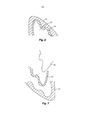
[038] As Figuras 4 a 11 são vistas esquemáticas em seção transversal que ilustram um método de produção de uma moldeira de transferência de acordo com uma modalidade e aspecto da invenção.[038] Figures 4 to 11 are schematic cross-sectional views that illustrate a method of producing a transfer tray according to an embodiment and aspect of the invention.
[039] A Figura 1 mostra um protótipo físico 1 representando um formato composto do formato positivo da arcada dentária de um paciente 2 e o formato positivo de um conjunto de análogos 3 (para fins de clareza, nem cada um dos análogos mostrados é referido por uma linha de referência na Figura). Os análogos 3 representam ou se aproximam de bráquetes ortodônticos como eles são usados, em combinação com um fio, para mover os dentes de um paciente desde um mau posicionamento na direção de uma posição desejada. No protótipo físico 1, os dentes de um paciente são representados estando mal posicionados, como ilustrado em mais detalhe na Figura 2.[039] Figure 1 shows a
[040] O protótipo físico 1 pode ser usado para dar formato, do ponto de vista físico, a uma moldeira de transferência (não mostrada nessa Figura) para colar bráquetes em uma posição predeterminada pela moldeira de transferência, nos dentes de um paciente. A moldeira de transferência forma uma réplica negativa de pelo menos parte do protótipo físico 1. Tal moldeira de transferência pode ser obtida, por exemplo, tirando-se uma impressão do protótipo físico 1, por moldagem com sobreposição do protótipo físico 1 ou com uma outra técnica na qual o modelo físico positivo 1 seja usado, de preferência, diretamente, conformando uma réplica negativa. O modelo físico 1 é configurado, de preferência, para fornecer cortes inferiores predeterminados que, por um lado, permitem que os bráquetes ortodônticos fiquem retidos ou seguros dentro da moldeira de transferência porém, por outro lado, facilitam uma remoção da moldeira de transferência do protótipo físico 1 ou dos dentes de um paciente sem destruir a moldeira de transferência ou quebrar um bráquete, tirando-o dos dentes de um paciente. Devido ao fato de o formato de bráquetes ortodônticos forma, com frequência, cortes inferiores que dificultam ou bloqueiam uma remoção não destrutiva da moldeira de transferência, os bráquetes são representados no protótipo físico 1 por análogos 3 que podem não formar réplicas exatas de bráquetes, mas apenas se aproximam do formato do bráquete para controlar cortes inferiores em direção a um nível desejado. Nota-se, no entanto, que um bráquete que encaixe com o nível desejado de cortes inferiores pode ser representado por um análogo que forma uma réplica exata daquele bráquete, enquanto um bráquete que forma um corte inferior indesejado, pode ser representado por um análogo que tenha um formato aproximado de tal bráquete. Consequentemente, uma moldeira de transferência replicada a partir do protótipo físico obtém, de preferência, um formato que tem o nível de recortes que permite a retenção dos bráquetes e a remoção não destrutiva dos dentes de um paciente.[040]
[041] O protótipo físico 1 no exemplo é produzido por fabricação aditiva e, assim, a arcada dentária 2 e os análogos 3 são formados em uma única peça no protótipo físico 1. O protótipo físico 1 pode, particularmente, não ser obtido ou consistir de um conjunto dos análogos 3 na arcada dentária 2. Consequentemente, a posição dos análogos 3 em relação à arcada dentária 2 pode ser determinada com o auxílio de computador e é possível evitar tolerâncias de montagem manuais.[041]
[042] A fabricação do protótipo físico nesse exemplo é baseada em um protótipo virtual preparado em um sistema de computador. Tal protótipo virtual corresponde, de preferência, a uma representação matemática de um formato tridimensional que pode ser processado por um computador, por exemplo, um sistema CAD (Computer Aided Design). Adicionalmente, o protótipo virtual está disponível, de preferência, na forma de um dado computacional que pode ser usado para controlar uma máquina de fabricação aditiva para produzir o protótipo físico em um formato conforme definido pelo protótipo virtual. O protótipo virtual pode ser projetado ou gerado a partir de superposição ou fusão de uma arcada dentária virtual de um paciente com um conjunto de análogos virtuais, como adicionalmente descrito na Figura 3.[042] The manufacture of the physical prototype in this example is based on a virtual prototype prepared on a computer system. Such a virtual prototype preferably corresponds to a mathematical representation of a three-dimensional format that can be processed by a computer, for example, a CAD (Computer Aided Design) system. In addition, the virtual prototype is preferably available in the form of computational data that can be used to control an additive manufacturing machine to produce the physical prototype in a format as defined by the virtual prototype. The virtual prototype can be designed or generated by superimposing or merging a patient's virtual dental arch with a set of virtual analogues, as additionally described in Figure 3.
[043] A Figura 3 mostra uma seção transversal de um protótipo virtual 10. O protótipo virtual 10 combina o formato de análogos virtuais (nessa vista representada pelo análogo virtual 12) e o formato de uma arcada dentária virtual 11. O análogo virtual 12 e a arcada dentária virtual 11 podem ser obtidos a partir de partes virtuais distintas independentes, ou fornecendo-se a arcada dentária 11 e adicionando-se o análogo virtual 12 à arcada dentária 11 com auxílio do computador, por exemplo, pelo projeto aditivo ou modificação da arcada dentária 11. O versado na técnica será capaz de usar outras técnicas, conforme conhecidas no campo de Projetos Auxiliados por Computador, para fornecer o protótipo virtual 10 e para combinar os formatos dos análogos virtuais e da arcada dentária virtual.[043] Figure 3 shows a cross section of a
[044] No exemplo, o análogo virtual 12 é obtido com base em (por exemplo, por modificação de) um bráquete virtual 13. No exemplo, refere-se a um bráquete lingual que é projetado e fabricado, tipicamente, individualmente para cada dente e paciente. O versado na técnica reconhecerá, no entanto, que, embora a presente invenção possa fornecer certas vantagens no uso de bráquetes linguais, ela pode ser usada, da mesma forma, em combinação com bráquetes labiais ou uma combinação de bráquetes linguais e labiais. Uma possibilidade de fornecer um bráquete virtual é descrita, por exemplo, em US 7.811.087. O projeto do bráquete pode ser feito em um computador que armazene uma arcada dentária virtual tridimensional de um paciente. A arcada dentária virtual pode ser obtida por meio de varredura dos dentes do paciente ou um modelo físico dos dentes do paciente. Dessa forma, o formato da arcada dentária de um paciente, compreendendo o formato dos dentes e a posição relativa entre os mesmos, pode ser fornecido na forma de uma representação processável por computador. O computador pode ser equipado com um, assim chamado, software de planejamento de tratamento que permite mover os dentes no modelo virtual ate posições finais desejadas. Um elemento importante do bráquete é o bloco por meio do qual o bráquete é ligado a um dente. A geometria do bloco voltado para o dente pode ser derivada diretamente de geometrias de dente representadas na arcada dentária virtual de modo que o bloco obtém uma superfície tridimensional que encaixa substancialmente exatamente na superfície de dente correspondente. Isso permite um posicionamento relativamente preciso do bráquete no dente e ajuda a maximizar a resistência da ligação. Uma outra parte do bráquete, o corpo de bráquete, que contém uma fenda para receber um fio e outros recursos que permitam a fixação do fio na fenda, pode estar disponível no computador como modelos virtuais predefinidos, por exemplo, na forma de uma biblioteca de corpos de bráquetes. Para fornecer um conjunto virtual de bráquetes à arcada dentária virtual, certas estruturas virtuais predefinidas podem ser definidas. Os corpos de bráquete são alinhados, de preferência, com suas fendas em relação uma à outra, por exemplo, de modo que um fio virtual em formato de U, pode passar através das fendas de todos os bráquetes. Uma vez que a posição da fenda dos corpos de bráquetes tenha sido determinada, os corpos de bráquetes e os respectivos blocos de bráquetes podem ser combinados, por exemplo, virtualmente fundidos para formar o conjunto de bráquetes virtuais. Os programas comuns de Desenho Auxiliado por Computador (CAD) têm capacidades (por exemplo, operações booleanas) para conectar formatos existentes entre si. Opcionalmente, o projeto dos bráquetes virtuais, ou de partes dos bráquetes, pode ser adaptado para levar em conta uma boa articulação, exigências de higiene ou outros aspectos, conforme for necessário.[044] In the example,
[045] Os bráquetes virtuais são usados para fornecer o conjunto de análogos baseados neles. Cada análogo do grupo de análogos é associado a um bráquete virtual do conjunto virtual de bráquetes. No exemplo, o análogo virtual 12 e o bráquete virtual 13 são associados e têm o mesmo formato nas primeiras áreas 12a, 13a, no entanto têm formatos diferentes nas segundas áreas 12b, 13b. Em particular, as segundas áreas 12b do análogo virtual 12 compreendem cortes inferiores reduzidos em relação aos cortes inferiores presentes nas segundas áreas 13b do bráquete virtual 13. No exemplo, os cortes inferiores são estruturas que retêm (em um protótipo físico) uma réplica imaginária 20 contra uma separação do protótipo virtual 10 em uma direção R. Assim, os cortes inferiores reduzidos nas segundas áreas 12b dos análogos 12 são dimensionados para fornecer uma retenção menor do que os cortes inferiores nas segundas áreas 13b dos bráquetes 13. Por conseguinte, em relação ao formato do bráquete 13, o formato do análogo 12 é adaptado para facilitar uma remoção de uma moldeira de transferência que é feita com base naquele formato de análogo. Como mencionado, um ou mais dos análogos virtuais pode corresponder substancialmente exatamente no formato ao formato do bráquete virtual, embora, na maioria dos casos, o formato de análogos virtuais e o formato de bráquetes virtuais possa diferir ao menos em áreas que compreendem cortes inferiores.[045] Virtual brackets are used to provide the set of analogues based on them. Each analogue in the analogue group is associated with a virtual bracket of the virtual bracket set. In the example,
[046] Os análogos virtuais podem ser fornecidos replicando-se virtualmente os bráquetes virtuais e eventualmente redesenhando uma ou mais porções do formato de bráquete virtual replicado. O computador pode ter capacidade para determinar uma força de retenção virtual dependendo dos cortes inferiores presentes em um ou mais dos análogos. Por exemplo, um número substancial e/ou alto de cortes inferiores presentes em um conjunto de análogos pode levar a uma força de retenção relativamente alta, enquanto um número substancialmente menor e/ou menor de cortes inferiores pode levar a uma força de retenção virtual mais baixa. Consequentemente, o computador pode ser adaptado para exibir uma força de retenção virtual e, opcionalmente, limites superior e inferior para uma força de retenção virtual desejada para um usuário. Por conseguinte, o usuário pode ajustar os cortes inferiores dos análogos pelo desenho. Dessa forma, a força de retenção da moldeira de transferência em relação ao modelo físico pode ser determinada durante o projeto virtual, o que pode minimizar a necessidade de ajustar fisicamente o protótipo físico e/ou a moldeira de transferência.[046] Virtual analogues can be provided by virtually replicating virtual brackets and eventually redrawing one or more portions of the replicated virtual bracket format. The computer may be able to determine a virtual holding force depending on the lower cuts present in one or more of the analogues. For example, a substantial and / or high number of lower cuts present in a set of analogues can lead to a relatively high holding force, while a substantially smaller and / or lesser number of lower cuts can lead to a more virtual holding force low. Consequently, the computer can be adapted to display a virtual holding force and, optionally, upper and lower limits for a desired virtual holding force for a user. Consequently, the user can adjust the lower cuts of the analogues by drawing. In this way, the retention force of the transfer tray in relation to the physical model can be determined during the virtual project, which can minimize the need to physically adjust the physical prototype and / or the transfer tray.
[047] Para fornecer um protótipo virtual, a arcada dentária virtual e o conjunto de análogos virtuais podem ser combinados, por exemplo fundidos ou superpostos com o auxílio do computador. O protótipo virtual, que está presente, de preferência, na forma de dados tridimensionais processáveis por computador, pode ser transmitido para uma máquina de fabricação aditiva que produz o protótipo físico com base no protótipo virtual.[047] To provide a virtual prototype, the virtual dental arch and the set of virtual analogues can be combined, for example, fused or overlaid with the aid of the computer. The virtual prototype, which is preferably present in the form of three-dimensional data that can be processed by a computer, can be transmitted to an additive manufacturing machine that produces the physical prototype based on the virtual prototype.
[048] A Figura 4 mostra um protótipo físico 20 que tem um conjunto de análogos, em que análogo 22 é representativo deste conjunto na Figura. O protótipo físico 20 representa ainda a arcada dentária de um paciente 21 que é representada por um dente 21’. O análogo 22 e o dente 21' são formados em uma peça, e, particularmente, não são montados, porém formados em um volume contíguo de material. Adicionalmente, embora não esteja ilustrado no exemplo, o conjunto completo de análogos e a arcada dentária são formados em uma peça. O análogo 22 tem uma área de corte inferior 22b que, com relação a uma área de corte inferior 23b (ilustrada em linhas pontilhadas/tracejadas) de um bráquete associado imaginário, é reduzida. Nota- se que o protótipo físico 20 realmente não inclui os bráquetes, e uma parte de um bráquete é fornecida na Figura apenas para ilustração da diferença geométrica entre o análogo 22 e o bráquete associado.[048] Figure 4 shows a
[049] O protótipo físico 20 no exemplo, é constituído de um material leve curável, mas, em outros exemplos, pode ser feito de um material plástico (por exemplo, fundido a partir de uma fibra plástica), metal, metal, gesso natural, cimento ou outros materiais quimicamente endurecíveis.[049]
[050] A Figura 5 mostra o protótipo físico 20 com uma cobertura elástica 24 e uma cobertura plástica 25. A cobertura elástica 24 é colocada no topo do lado de oclusão dos dentes, representado pelo protótipo físico 20, e no topo da cobertura elástica 24, é disposta uma cobertura plástica. A cobertura elástica com a cobertura plástica é deformada, de preferência por uma pressão de ar P aplicada na cobertura elástico e cobertura plástica 24, 25 em direções ao encontro do protótipo físico 20. Isso pode ser conseguido por um vácuo gerado abaixo das coberturas elástica e plástica 24, 25 ou uma pressão acima das coberturas elástica e plástica 24, 25. Ao menos a cobertura plástica 25 pode ser aquecida antes e/ou durante a deformação. Como resultado, as coberturas elástica e plástica 24, 25 são deformadas como ilustrado na Figura 6.[050] Figure 5 shows the
[051] A Figura 6 mostra o protótipo físico 20 abarcado pela cobertura elástica 24 e a cobertura plástica 25. A cobertura plástica 25 é, de preferência, um filme termoplástico transparente que se conforma à superfície externa da cobertura elástica 24. De preferência, deixa-se a cobertura plástica 25 solidificar por resfriamento de modo que ela seja dotada de rigidez suficiente para manuseio. Como ilustrado, a cobertura elástica 24 espaça a cobertura plástica 25 do protótipo físico 20.[051] Figure 6 shows the
[052] Em um outro exemplo (não mostrado), ao invés de uma cobertura elástica, pode ser usado um revestimento espaçador. Tal revestimento espaçador pode ser obtido da aplicação de um líquido solidificável ou material pastoso sobre o protótipo físico 20, e permitindo que o material solidifique. Isso pode ser feito por revestimento por imersão, ou revestimento manual com o uso de uma seringa ou escova dispensadora. No estado solidificado, o material de revestimento, de preferência, é elástico ou frágil, de modo que ele seja removido do protótipo físico em um estágio posterior. Uma cobertura plástica pode ser deformada sobre o protótipo revestido, como descrito acima.[052] In another example (not shown), instead of an elastic covering, a spacer coating can be used. Such a spacer coating can be obtained by applying a solidifiable liquid or pasty material over the
[053] Ainda em um outro exemplo, pode ser aplicado um revestimento espaçador em uma máquina de fabricação aditiva junto com a construção do modelo físico. Em tal processo de construção, um material relativamente duro e um material relativamente macio podem ser impressos em três dimensões, com o material duro formando o protótipo físico e o material macio formando o revestimento espaçador. O material macio pode ser um, assim chamado, material de suporte, que é usado tipicamente para impressão vertical, em forma de camada, de estruturas verticalmente espaçadas e removidas após a impressão. Uma máquina de fabricação aditiva que forneça tal processo de impressão está disponível, por exemplo, sob a designação Projet™ Series da empresa 3D Systems, EUA.[053] In yet another example, a spacer coating can be applied to an additive manufacturing machine along with the construction of the physical model. In such a construction process, a relatively hard material and a relatively soft material can be printed in three dimensions, with the hard material forming the physical prototype and the soft material forming the spacer coating. The soft material can be a so-called backing material, which is typically used for vertical, layer-shaped printing of vertically spaced structures and removed after printing. An additive manufacturing machine that provides such a printing process is available, for example, under the designation Projet ™ Series from 3D Systems, USA.
[054] A Figura 7 ilustra uma separação da cobertura elástica 24 do protótipo físico 20 e da cobertura plástica 25. A cobertura elástica 24 pode ser disposta e o protótipo físico 20 e a cobertura plástica 25 pode ser usada para formar a moldeira de transferência para bráquetes, conforme descrito a seguir.[054] Figure 7 illustrates a separation of the
[055] A Figura 8 mostra a cobertura plástica 25 que tem uma cavidade formada na cobertura plástica 25 por meio do uso do protótipo físico revestido, como descrito acima. Um material solidificável, de preferência, transparente, 26’ é recebido no interior da cavidade da cobertura plástica 25. O protótipo físico 20 é encaixado na cobertura plástica 25 e assim, imerso no material solidificável 26' que, desse modo, distribui preferencialmente entre a superfície externa do protótipo físico e a superfície interna da cavidade, conforme mostrado na Figura 9. Opcionalmente, o protótipo físico combinado 20, o material solidificável 26' e a cobertura plástica 25 são expostos a uma sobrepressão em relação à pressão atmosférica normal para minimizar os espaços vazios ou bolhas no material solidificável 26’, em particular entre a superfície externa do protótipo físico 20 e a superfície interna do material solidificável 26’. Deixa-se o material solidificável 26’ solidificar para fornecer uma camada de posicionamento 26 aos bráquetes. A camada de posicionamento 26 em combinação com a cobertura plástica 25 forma a moldeira de transferência 27. A camada de posicionamento 26 é adaptada, de preferência, de modo que ela possa posicionar e reter o bráquete e, adicionalmente, tal que ela seja deformável para receber nela bráquetes e remover os bráquetes dali. Consequentemente, a camada de posicionamento 26 pode ser produzida a partir de um material relativamente elástico e macio (quando solidificado). Portanto, a moldeira de transferência 27 compreende a cobertura plástica 25, que fornece à moldeira, de preferência, a rigidez e estabilidade mecânica necessárias, e a camada de posicionamento 26, que fornece à moldeira de transferência, de preferência, receptáculos nos quais o bráquete pode ser retido de modo preciso e removível. A camada de posicionamento 26 tem formato aproximadamente correspondente ao formato da cobertura elástica descrita acima, no entanto, de preferência, é formada de um material diferente.[055] Figure 8 shows the
[056] A camada de posicionamento 26 e a cobertura plástica 25 podem ter o tamanho desbastado para corresponder a apenas uma parte da arcada dentária de um paciente ou fazer a moldeira encaixar convenientemente na boca de um paciente. Para uso da moldeira de transferência 27, como ilustrado na Figura 10, bráquetes (representados pelo bráquete 30) são colocados em receptáculos associados na camada de posicionamento 26. Adicionalmente, a camada de posicionamento 26 e a cobertura plástica são correlacionadas. A moldeira de transferência combinada 27 que inclui o bráquete 30 colocado na camada de posicionamento 26, conforme mostrado na Figura 11. Um adesivo pode ser aplicado à superfície do bloco 31 do bráquete (é bráquetes adicionais presentes na moldeira) e a moldeira de transferência pode ser colocada nos dentes da boca de um paciente, onde se faz com que o adesivo endureça, ou onde se deixa ele endurecer, para estabelecer uma ligação entre os bráquetes na moldeira e os dentes do paciente. Uma vez que seja estabelecida a ligação, a cobertura plástica 25 pode ser removida, deixando a camada de posicionamento 26 no lugar nos dentes do paciente. A camada de posicionamento 26, devido a suas propriedades elásticas e não sendo mais suportada pela cobertura plástica 25, pode, dessa forma, ser facilmente descascada dos dentes do paciente e os bráquetes podem ser colados ali. Conforme mostrado na Figura, os espaços entre a camada de posicionamento 26 e o bráquete 30 estão presentes em áreas de corte inferior do bráquete 30, facilitando assim a separação entre a camada de posicionamento 26 e o bráquete 30. Por conseguinte, as forças nos bráquetes ligados aos dentes do paciente e, desse modo, o risco de quebrar ou afetar as uniões durante a remoção da moldeira de transferência, são minimizadas.[056] The
[057] Devido ao uso de materiais transparentes para a camada de posicionamento 26 e para a cobertura plástica 25, o posicionamento adequado da moldeira de transferência 27, nos dentes de um paciente, é facilitado. Adicionalmente, o material transparente permite determinar visualmente um posicionamento adequado das braçadeiras dentro da moldeira de transferência.[057] Due to the use of transparent materials for the
Claims (8)
Applications Claiming Priority (3)
| Application Number | Priority Date | Filing Date | Title |
|---|---|---|---|
| EP12196586.7 | 2012-12-11 | ||
| EP12196586 | 2012-12-11 | ||
| PCT/US2013/073041 WO2014093084A1 (en) | 2012-12-11 | 2013-12-04 | Mockup representing a dental arch including analogs approximating orthodontic brackets and method of making the mockup |
Publications (2)
| Publication Number | Publication Date |
|---|---|
| BR112015013508A2 BR112015013508A2 (en) | 2017-07-11 |
| BR112015013508B1 true BR112015013508B1 (en) | 2021-02-23 |
Family
ID=47429629
Family Applications (1)
| Application Number | Title | Priority Date | Filing Date |
|---|---|---|---|
| BR112015013508-0A BR112015013508B1 (en) | 2012-12-11 | 2013-12-04 | method of producing a physical prototype |
Country Status (12)
| Country | Link |
|---|---|
| US (1) | US10639130B2 (en) |
| EP (1) | EP2931166B1 (en) |
| JP (1) | JP6478918B2 (en) |
| KR (1) | KR102157136B1 (en) |
| CN (1) | CN104837435B (en) |
| AU (2) | AU2013359874B2 (en) |
| BR (1) | BR112015013508B1 (en) |
| DK (1) | DK2931166T3 (en) |
| IL (1) | IL239299B (en) |
| RU (1) | RU2638618C2 (en) |
| SG (1) | SG11201504611PA (en) |
| WO (1) | WO2014093084A1 (en) |
Families Citing this family (36)
| Publication number | Priority date | Publication date | Assignee | Title |
|---|---|---|---|---|
| US20140067334A1 (en) * | 2012-09-06 | 2014-03-06 | Align Technology Inc. | Method and a system usable in creating a subsequent dental appliance |
| US9427291B2 (en) | 2012-10-30 | 2016-08-30 | University Of Southern California | Orthodontic appliance with snap fitted, non-sliding archwire |
| EP2886077A1 (en) | 2013-12-18 | 2015-06-24 | 3M Innovative Properties Company | Method of making a transfer tray |
| EP2957252B8 (en) * | 2014-06-16 | 2017-08-30 | CA DIGITAL GmbH | Method for the production of a three-dimensional true model of the actual position of at least two the teeth of a patient |
| US10335250B2 (en) | 2015-10-07 | 2019-07-02 | uLab Systems, Inc. | Three-dimensional printed dental appliances using lattices |
| US10631953B2 (en) * | 2015-10-07 | 2020-04-28 | uLab Systems, Inc. | Three-dimensional printed dental appliances using support structures |
| US10624717B2 (en) | 2015-10-07 | 2020-04-21 | Ulab Systems Inc. | Tooth modeling system |
| US10357336B2 (en) | 2015-10-07 | 2019-07-23 | uLab Systems, Inc. | Systems and methods for fabricating dental appliances or shells |
| US11583365B2 (en) | 2015-10-07 | 2023-02-21 | uLab Systems, Inc. | System and methods for tooth movement as a flock |
| CN106420076B (en) * | 2016-07-29 | 2019-09-27 | 杭州一牙数字口腔有限公司 | Invisible orthotic device and preparation method thereof with pressure attachment |
| WO2018030576A1 (en) * | 2016-08-09 | 2018-02-15 | 주식회사 디오 | Digital bracket for tooth-correction by using digital library and method for manufacturing same |
| US10357342B2 (en) | 2016-09-21 | 2019-07-23 | uLab Systems, Inc. | Digital dental examination and documentation |
| CN110177521A (en) | 2016-12-02 | 2019-08-27 | 斯威夫特健康系统有限公司 | Indirect Orthodontic bonding system and method for bracket placement |
| EP4279020A3 (en) | 2017-01-31 | 2024-01-24 | Swift Health Systems Inc. | Hybrid orthodontic archwires |
| US11612458B1 (en) | 2017-03-31 | 2023-03-28 | Swift Health Systems Inc. | Method of tongue preconditioning in preparation for lingual orthodontic treatment |
| CN114129289A (en) | 2017-04-21 | 2022-03-04 | 斯威夫特健康系统有限公司 | Indirect-bonded tray, non-slip orthodontic appliance and registration system using the same |
| US11597830B2 (en) | 2017-06-20 | 2023-03-07 | 3M Innovative Properties Company | Radiation curable composition for additive manufacturing processes |
| US11317993B2 (en) * | 2018-02-09 | 2022-05-03 | Spartan Orthodontics Inc. | Orthodontic device for overbite correction |
| WO2019241253A1 (en) | 2018-06-12 | 2019-12-19 | Lightforce Orthodontics, Inc. | Ceramic processing and design for the direct manufacture of customized labial and lingual orthodontic clear aligner attachments |
| EP3581145B1 (en) * | 2018-06-12 | 2022-12-21 | 3C | Assembly for the placement of an orthodontic bracket and method for manufacturing such assembly |
| CN109394364B (en) * | 2018-10-29 | 2021-07-13 | 山东迈尔医疗科技有限公司 | Novel 3D printing movable denture support manufacturing process |
| US10315353B1 (en) | 2018-11-13 | 2019-06-11 | SmileDirectClub LLC | Systems and methods for thermoforming dental aligners |
| JP6942783B2 (en) | 2019-01-04 | 2021-09-29 | 澄祥 洪 | Improved indirect bonding method for orthodontic brackets |
| US11007042B2 (en) | 2019-02-06 | 2021-05-18 | Sdc U.S. Smilepay Spv | Systems and methods for marking models for dental aligner fabrication |
| US10482192B1 (en) | 2019-02-12 | 2019-11-19 | SmileDirectClub LLC | Systems and methods for selecting and marking a location on a dental aligner |
| US20220218452A1 (en) * | 2019-05-31 | 2022-07-14 | 3M Innovative Properties Company | Automated creation of tooth restoration dental appliances |
| EP4335640A2 (en) | 2019-09-18 | 2024-03-13 | 3M Innovative Properties Company | Methods of manufacturing a transfer apparatus including gingivally extending channels |
| US11273008B2 (en) | 2019-12-04 | 2022-03-15 | Oxilio Ltd | Systems and methods for generating 3D-representation of tooth-specific appliance |
| WO2021124335A1 (en) * | 2019-12-18 | 2021-06-24 | Ariel Scientific Innovations Ltd. | Orthodontic wire manipulation recommendation system |
| US11925526B2 (en) | 2019-12-23 | 2024-03-12 | 3M Innovative Properties Company | Custom tools for bonding orthodontic appliances and methods of bonding orthodontic appliances |
| EP4081161B8 (en) * | 2019-12-27 | 2024-03-20 | Solventum Intellectual Properties Company | Preformed orthodontic aligner attachments |
| WO2021214613A1 (en) | 2020-04-24 | 2021-10-28 | 3M Innovative Properties Company | An indirect bonding tray for bonding orthodontic appliances and methods of making and using the same |
| KR102532464B1 (en) * | 2020-12-29 | 2023-05-17 | 주식회사 디오코 | Method for manufacturing customized indirect bonding tray for dental, customized indirect bonding tray manufactured by the same, and simulator for producing virtual guide |
| US20220202534A1 (en) * | 2020-12-29 | 2022-06-30 | Mark A. Payne | Distalizer and method of assembly |
| US20230032861A1 (en) * | 2021-07-30 | 2023-02-02 | Baker Hughes Oilfield Operations Llc | Representative part, methods of designing representative parts, methods of forming and testing representative parts, and methods of qualifying additive manufacturing systems |
| WO2024018305A1 (en) | 2022-07-21 | 2024-01-25 | 3M Innovative Properties Company | Curable composition for producing transparent orthodontic attachments |
Family Cites Families (26)
| Publication number | Priority date | Publication date | Assignee | Title |
|---|---|---|---|---|
| US4160322A (en) | 1976-12-29 | 1979-07-10 | Frazier Paul D | Method of constructing an orthodontic appliance |
| US4551096A (en) | 1983-12-19 | 1985-11-05 | Dellinger Eugene L | Orthodontic apparatus and method for treating malocclusion |
| US5011405A (en) | 1989-01-24 | 1991-04-30 | Dolphin Imaging Systems | Method for determining orthodontic bracket placement |
| ATE145125T1 (en) | 1991-03-06 | 1996-11-15 | Ormco Corp | ORTHODONTIC SUPPORT AND METHOD FOR PRODUCING THE SAME |
| WO1994010935A1 (en) | 1992-11-09 | 1994-05-26 | Ormco Corporation | Custom orthodontic appliance forming method and apparatus |
| US5863198A (en) | 1996-09-23 | 1999-01-26 | Doyle; Walter A. | Orthodontic bracket placement jig |
| US5879158A (en) | 1997-05-20 | 1999-03-09 | Doyle; Walter A. | Orthodontic bracketing system and method therefor |
| US6471511B1 (en) | 1997-06-20 | 2002-10-29 | Align Technology, Inc. | Defining tooth-moving appliances computationally |
| US5971754A (en) | 1998-07-30 | 1999-10-26 | Sondhi; Anoop | Indirect bonding method and adhesive for orthodontic treatment |
| WO2000032132A1 (en) | 1998-11-30 | 2000-06-08 | Align Technology, Inc. | Attachment devices and methods for a dental appliance |
| US6123544A (en) * | 1998-12-18 | 2000-09-26 | 3M Innovative Properties Company | Method and apparatus for precise bond placement of orthodontic appliances |
| ATE488313T1 (en) | 2000-04-19 | 2010-12-15 | Orametrix Inc | BENDING MACHINE FOR A MEDICAL DEVICE |
| EP2204136B1 (en) | 2000-04-19 | 2013-08-28 | OraMetrix, Inc. | Orthodontic archwire |
| US6776614B2 (en) | 2002-02-13 | 2004-08-17 | Lingualcare, Inc. | Modular system for customized orthodontic appliances |
| US6905337B1 (en) | 2002-09-17 | 2005-06-14 | Orametrix, Inc. | Tooth templates for bracket positioning and other uses |
| US8251699B2 (en) | 2002-12-31 | 2012-08-28 | Brian C. Reising | Orthodontic bracket and method of attaching orthodontic brackets to teeth |
| US7020963B2 (en) | 2003-05-02 | 2006-04-04 | 3M Innovative Properties Company | Method and apparatus for indirect bonding of orthodontic appliances |
| EP1570803B1 (en) | 2004-03-04 | 2018-12-05 | Align Technology, Inc. | Systems and methods for fabricating a dental template |
| US20060025782A1 (en) * | 2004-07-28 | 2006-02-02 | Steven Klein | Eliminator a personal appliance to assist in fecal evacuation for patients with rectal hernia (rectocele) |
| US7168950B2 (en) * | 2004-10-18 | 2007-01-30 | 3M Innovative Properties Company | Orthodontic methods and apparatus for applying a composition to a patient's teeth |
| US7762815B2 (en) * | 2005-05-13 | 2010-07-27 | 3M Innovative Properties Co. | Method of making an indirect bonding tray for orthodontic treatment |
| US8562339B2 (en) * | 2007-07-13 | 2013-10-22 | 3M Innovative Properties Company | Digital orthodontic appliance coupling matrix |
| FR2924921B1 (en) | 2007-12-13 | 2010-08-20 | Daniel Julie | OPTIMIZED DESIGN PROCESS FOR PERSONALIZED ORTHODONTIC EQUIPMENT WITH STANDARD ATTACHES |
| US8235715B2 (en) * | 2008-12-18 | 2012-08-07 | Align Technology, Inc. | UV and chemical cure blocking dental template |
| JP5605645B2 (en) | 2010-12-27 | 2014-10-15 | 株式会社吉野工業所 | Plastic container |
| WO2012136247A1 (en) * | 2011-04-05 | 2012-10-11 | Yong-Min Jo | Method for producing trays for brackets |
-
2013
- 2013-12-04 RU RU2015126462A patent/RU2638618C2/en active
- 2013-12-04 BR BR112015013508-0A patent/BR112015013508B1/en active IP Right Grant
- 2013-12-04 WO PCT/US2013/073041 patent/WO2014093084A1/en active Application Filing
- 2013-12-04 EP EP13808411.6A patent/EP2931166B1/en active Active
- 2013-12-04 DK DK13808411.6T patent/DK2931166T3/en active
- 2013-12-04 US US14/651,440 patent/US10639130B2/en active Active
- 2013-12-04 CN CN201380064941.5A patent/CN104837435B/en active Active
- 2013-12-04 KR KR1020157018022A patent/KR102157136B1/en active IP Right Grant
- 2013-12-04 SG SG11201504611PA patent/SG11201504611PA/en unknown
- 2013-12-04 JP JP2015547410A patent/JP6478918B2/en active Active
- 2013-12-04 AU AU2013359874A patent/AU2013359874B2/en active Active
-
2015
- 2015-06-09 IL IL239299A patent/IL239299B/en active IP Right Grant
-
2017
- 2017-05-19 AU AU2017203368A patent/AU2017203368B2/en active Active
Also Published As
| Publication number | Publication date |
|---|---|
| AU2013359874B2 (en) | 2017-03-09 |
| AU2017203368A1 (en) | 2017-06-08 |
| BR112015013508A2 (en) | 2017-07-11 |
| IL239299B (en) | 2020-11-30 |
| AU2013359874A1 (en) | 2015-07-02 |
| WO2014093084A1 (en) | 2014-06-19 |
| JP2016500288A (en) | 2016-01-12 |
| AU2017203368B2 (en) | 2018-08-23 |
| CN104837435B (en) | 2019-11-01 |
| RU2638618C2 (en) | 2017-12-14 |
| EP2931166B1 (en) | 2019-10-09 |
| IL239299A0 (en) | 2015-07-30 |
| DK2931166T3 (en) | 2019-12-16 |
| US20150313687A1 (en) | 2015-11-05 |
| KR20150095747A (en) | 2015-08-21 |
| SG11201504611PA (en) | 2015-07-30 |
| CN104837435A (en) | 2015-08-12 |
| US10639130B2 (en) | 2020-05-05 |
| EP2931166A1 (en) | 2015-10-21 |
| KR102157136B1 (en) | 2020-09-17 |
| JP6478918B2 (en) | 2019-03-06 |
| RU2015126462A (en) | 2017-01-17 |
Similar Documents
| Publication | Publication Date | Title |
|---|---|---|
| BR112015013508B1 (en) | method of producing a physical prototype | |
| KR102332888B1 (en) | Method of making a transfer tray | |
| US11317990B2 (en) | Reduced registration bonding template | |
| US9918810B2 (en) | Method for producing a dental prosthesis with a template | |
| CN111107804A (en) | Tooth repairing mould | |
| US10390907B2 (en) | Method for producing trays for brackets | |
| KR101804991B1 (en) | Mould type jig for bonding orthodontic brackets and mould type jig | |
| CN114144142B (en) | Additive manufactured denture base with buttress | |
| JP2022550278A (en) | Transfer device including gingivally extending channel and associated method of manufacture | |
| KR20220165716A (en) | Bracket Processing Instrument, Manufacturing Method For The Same, And Dental Mockup For The Same |
Legal Events
| Date | Code | Title | Description |
|---|---|---|---|
| B06U | Preliminary requirement: requests with searches performed by other patent offices: procedure suspended [chapter 6.21 patent gazette] | ||
| B09A | Decision: intention to grant [chapter 9.1 patent gazette] | ||
| B16A | Patent or certificate of addition of invention granted [chapter 16.1 patent gazette] |
Free format text: PRAZO DE VALIDADE: 20 (VINTE) ANOS CONTADOS A PARTIR DE 04/12/2013, OBSERVADAS AS CONDICOES LEGAIS. |